

Page 1
H
R
aallll
H
eesseeaarrcchh
R
T
eecchhnnoollooggiieess,, IInncc..
T
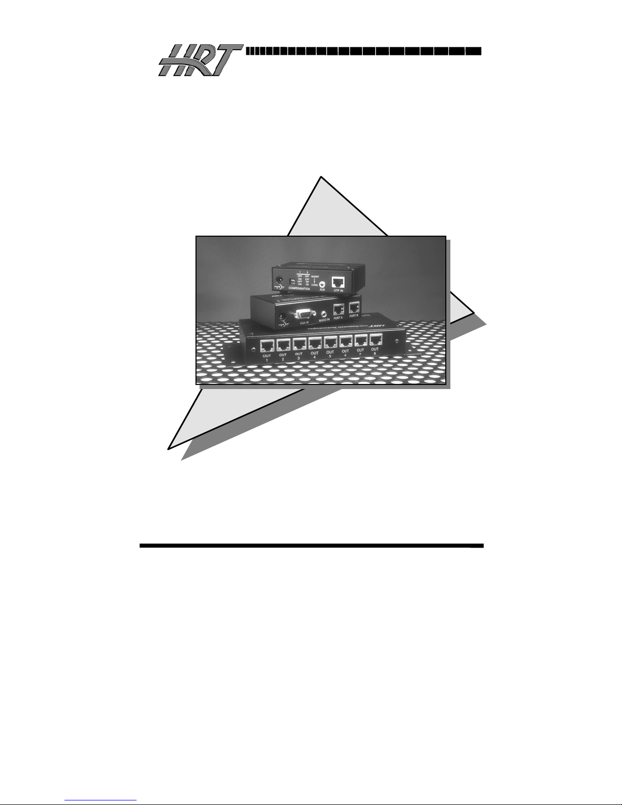
Compact UTP (Cat5) Audio Video Splitter
and Receiver
MODEL
MODEL
MODEL
MODEL
UTP VGA/AUDIO 2-PORT SENDER
2
UUVVAA--2
UTP VGA/AUDIO 8-PORT SENDER
8
UUVVAA--8
UTP VGA/AUDIO RECEIVER
A
UURRA
UTP RECEIVER with SKEW COMPENSATION
C
UURRAA--SSC
Revision A
CUSTOMER
SUPPORT
INFORMATION
Order toll-free in the U.S. 800-959-6439
FREE technical support, Call 714-641-6607 or fax 714-641-6698
Mail order: Hall Research Technologies, 3613 W.MacArthur Blvd. #612, Santa Ana, CA 92704
Web site: www.hallresearch.com • E-mail: info@ hallresearch.com
Page 2

Page 3

Compact CAT5 Audio/Video Splitters and Receive
r
ss
TRADEMARKS USED IN THIS MANUAL
Hall Research, HRT, and (logo) are trademarks of Hall
Research Technologies, Inc.
Apple and Macintosh are registered trademarks of Apple Computer, Inc.
IBM is a registered trademark of International Business Machines
Corporation.
SGI is a registered trademark of Silicon Graphics, Inc.
Sun and Sun Microsystems are registered trademarks of Sun Microsystems,
Inc. in the United States and other countries.
Any other trademarks mentioned in this manual are acknowledged to be the
property of the trademark owners.
1
Page 4

Compact CAT5 Audio/Video Splitters and Receiver
FEDERAL COMMUNICATIONS COMMISSION
AND CANADIAN DEPARTMENT OF COMMUNICATIONS
RADIO FREQUENCY INTERFERENCE STATEMENTS
This equipment generates, uses, and can radiate radio frequency energy
and if not installed and used properly, that is, in strict accordance with
the manufacturer’s instructions, may cause interference to radio
communication. It has been designed and found to comply with the
limits for a Class A computing device in accordance with the
specifications in Subpart B of Part 15 of FCC rules, which are intended
to provide reasonable protection against such interference when the
equipment is operated in a commercial environment. Operation of this
equipment in a residential area is likely to cause interference, in which
case the user at his own expense will be required to take whatever
measures may be necessary to correct the interference.
Changes or modifications not expressly approved by the party
responsible for compliance could void the user’s authority to operate
the equipment.
This digital apparatus does not exceed the Class A limits for radio
noise emission from digital apparatus set out in the Radio Interference
Regulation of the Canadian Department of Communications.
Le présent appareil numérique n’émet pas de bruits radioélectriques
dépassant les limites applicables aux appareils numériques de la classe
A prescrites dans le Règlement sur le brouillage radioélectrique publié
par le ministère des Communications du Canada
2
Page 5

Compact CAT5 Audio/Video Splitters and Receive
r
ss
Contents
1. Introduction ..............................................................................page 4
1.1 General ................................................................................page 4
1.2 Features ...............................................................................page 4
2. Installation .................................................................................page 5
3. Configuration and Operation ....................................................page 7
3.1 Sender ..................................................................................page 7
3.2 Receiver ...............................................................................page 7
3.2.1 Skew compensation (applies to Model URA-SC only).....page 8
4. Troubleshooting.........................................................................page 9
4.1 Problem Solving FAQ..........................................................page 9
4.2 Calling Hall Research Technologies ..................................page 11
4.3 Shipping & Packaging .......................................................page 12
5. Specifications...........................................................................page 13
ACCESSORIES ..........................................................................page 15
3
Page 6

Compact CAT5 Audio/Video Splitters and Receiver
1. Introduction
1.1 General
The Models UVA-2 and UVA-8 are respectively 2 and 8-channel UTP
(CAT5) VGA video splitters (senders) with audio. The devices convert
a PC's VGA and audio signals into a format that can be transmitted
using a single inexpensive and commonly available Category-5
Unshielded Twisted Pair (UTP) cable with RJ45 connectors, which are
used in most Local Area Networks.
At the receiving (remote) end a matching receiver Model URA (sold
separately) is used to convert the UTP signal back to VGA and audio.
The devices are housed in compact shielded enclosures and include
connectors for the local monitor and speakers as well as multiple RJ45
connectors for connection to remote monitors.
Included with the devices are: a small power adapter, and the senders
also come with short video and audio cables for connection to the PC’s
VGA and sound card’s outputs.
The RJ45 outputs on the Splitters can drive CAT5 LAN cables to 500
feet (152 meters) with little to no degradation of video quality (see
table 3.2). A proprietary circuit in the receiver is used to compensate
for signal losses in long cable runs.
1.2 Features
• Support for local monitor and speaker at sending end
• Handles resolutions up to 1280x1024 at any refresh rate
• Rugged, Reliable, Compact size
• No software required
• Drive standard CAT5 cables to 500 feet
• Transmit audio and video signals on one cable
• Easily expand Splitters by daisy-chaining the local in/out ports
• User selectable cable length compensation at each URA
receiver
4
Page 7
Compact CAT5 Audio/Video Splitters and Receive
r
2. Installation
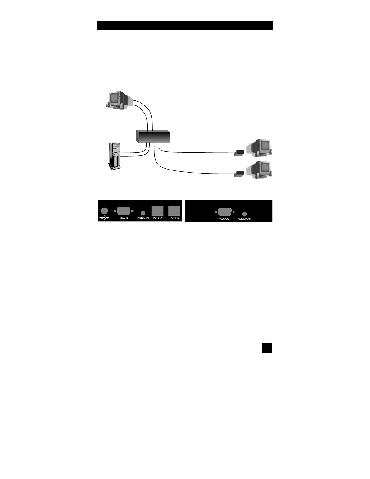
1. Connect the VGA IN and AUDIO IN connectors of the UVA-x to
the computer's video and speaker ports using the supplied cables
(see figures 2.1 and 2.2).
Local
Monitor and
Speakers
Remote Monitors &
Speakers
VGA &
Audio
UVA-X
CAT5
CAT5
URA
URA
ss
Figure 2.1
Figure 2.2 Figure 2.3
2. Connect the local monitor and speakers to the device's VGA OUT
and AUDIO OUT connectors respectively. (see Figure 2.3)
NOTE
To expand the number of outputs, use these ports to daisy
chain to another UVA-x’s VGA and audio inputs. Connect the
local monitor and speakers to the last unit in the chain.
3. Connect the supplied power adapter to the power input connector
on the unit.
4. Using Category-5 cable connect one or more URA receivers to the
unit's RJ45 outputs. The outputs are labeled PORT A and PORT B
on the UVA-2 or OUT 1 through OUT 8 on UVA-8.
5
Page 8
Compact CAT5 Audio/Video Splitters and Receiver
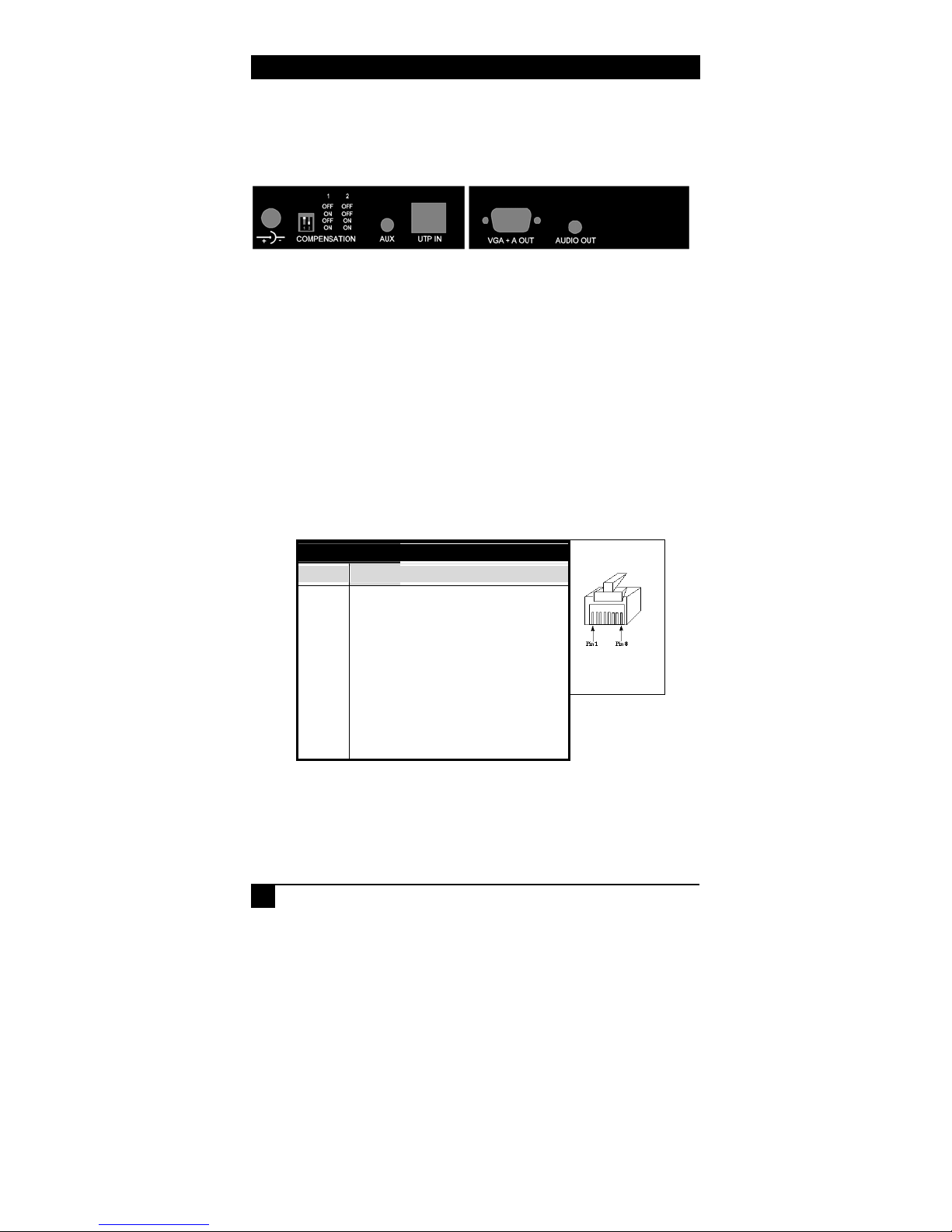
5. Connect the remote monitor and speakers to the receiver unit and
attach the power adapter to the receiver
Figure 2.4 Figure 2.5
CAUTION
Before plugging in the remote monitor, verify that the AC line is properly
wired and that a protective ground (green) wire is established with NO
potential difference between both the sender and receiver locations (The
splitter can tolerate up to 5 v peak-to-peak ground noise between the two
locations) . Failure to ensure good grounding can result in erratic operation
and possible shock hazards or damage to your equipment.
NOTICE
Do not connect this unit to any LAN device such as network cards or hubs
as this may damage the UVA/URA and/or the LAN device. Use EIA/TIA 568B
standard straight-through patch wiring as shown below. Do not use
crossover cables.
EIA/TIA 568B WIRING STANDARD
PIN Wire Color
1 White w/ Orange Stripe
2 Orange
3 White w/Green Stripe
4 Blue
5 White w/Blue Stripe
6 Green
7 White w/Brown Stripe
8 Brown
6
Page 9
Compact CAT5 Audio/Video Splitters and Receive
r
ss
3. Configuration & Operation
3.1 Sender
At the sending end the video signal from the PC is fully terminated and
buffered for the local video output connector. This means that
terminating or plugging a local monitor is not necessary and this
connector can be left open.
The stereo audio input is passed through to the local audio output
connector and the audio integrity is fully preserved. The transmitted
audio in the CAT5 cable to the remote receiver is monaural. The audio
outputs are “line-level” and powered speakers are required.
3.2 Receiver
The only thing that requires configuration on the regular URA is the
COMPENSATION switch setting. URA-SC also requires setting of
“skew” adjustment pots discussed in section 3.2.1.
Please refer to Figure 2.3 for the location of the dip switch. The Switch
has two levers. When the lever is down the switch is ON.
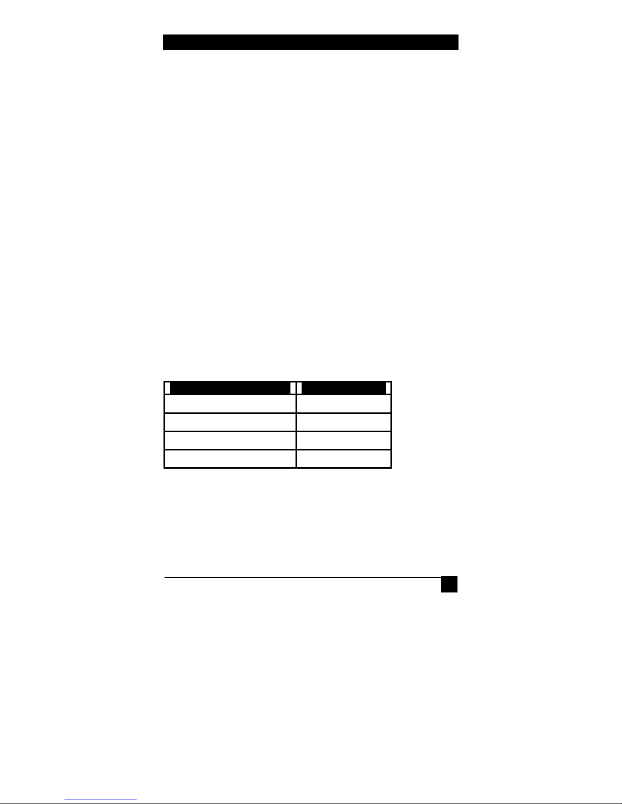
Referring to Table 3.1 and set the dip switches according to the cable
length used.
S1/S2 Switch (Up = OFF) Cable Length
OFF/OFF position 0 to 125 feet
ON/OFF position 125 to 225 feet
OFF/ON position 225 to 375 feet
ON/ON position 375 to 500+ feet
Assuming that there are no major grounding or large EMI noise
problems present, the video quality at the remote station depends on the
length of the CAT5 cable, actual video resolution and refresh rate.
The Model URA receiver employs proprietary user settable video
compensation to enhance the image quality when long cables are used.
Table 3.1
7
Page 10
Compact CAT5 Audio/Video Splitters and Receiver
In general at low and mid resolutions excellent image reproduction is
provided at up to 500 feet. At high resolution and refresh rates perfect
image reproduction can be achieved at shorter distances (see table 3.2
below). Using longer cables or higher resolution rates will still produce
an image, but the reproduction quality will be reduced.
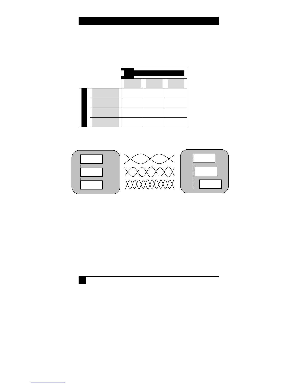
Refresh Rate
60 Hz 75 Hz 85 Hz
640x480 500 ft 500 ft 500 ft
800x600 500 ft 500 ft 400 ft
1024x768 500 ft 400 ft 350 ft
Resolution
1280x1024 500 ft 350 ft 300 ft
Table 3.2
3.2.1 Skew compensation (applies to Model URA-SC only)
RED
GREEN
BLUE
Figure 3.1
RED
GREEN
BLUE
As shown in figure 3.1 above, a characteristic of Category-5 cable is
that the pairs of wires are twisted at different rates inside the cable.
Therefore, for a given length of Cat-5 cable the total length of a
particular pair could be longer than others. Since the signals travel in
the cable at a fixed rate (approximately 90% of light speed), The arrival
times of signals can be skewed in a long cable (those that have to travel
farther arrive later and the corresponding image shifts to the right).
This is seen on the monitor as separation, or lack of convergence in
colors. For example a vertical white line on the screen may look to
have a red tinge on the left edge and blue tinge on the right edge.
8
Page 11

Compact CAT5 Audio/Video Splitters and Receive
r
This effect gets worse at high resolutions, high refresh rates, long
cables (in excess of 200-300 feet), and depends on the cable
construction itself. Hall Research recommends standard Cat5 rather
than Cat5e or Cat6, since the twist ratio match is worse in Cat6 cable.
To compensate for this skew, the Model URA-SC provides “skewcompensation” pots. The pots are adjusted by a screwdriver and need
to be only set once per installation (adjustment is independent of
resolution and refresh rate).
3 pots are provided, one for each color. Turn all the pots CCW (no
delay), and then turn the pots for the colors arriving early, pushing its
image to the right, to lineup with the slowest color.
This effect is very subtle as you can only move each color component
only by a few pixels. But with a steady hand and good eyes you should
be able to improve the image quality. To help you with the alignment
you can download test patterns especially designed for skew
compensation from our website.
4. Troubleshooting
ss
4.1 Problem Solving FAQ
1. Fuzzy, blurry, or ghosting image at remote location
If you have a stable image but it looks somewhat blurry (object or
character edges are not sharp), make sure that you have set the receiver
unit’s compensation switches correctly. Also check table 3.2 to see that
you have not exceeded the maximum cable length recommendation. If
you still have a fuzzy image, try reducing the refresh rate and/or
resolution of the PC. You may also wish to purchase a URA-SC to
adjust lack of convergence among the red, green, and blue colors.
If too much compensation is applied at the receiver, a bright and
ghosting image may result. In this case try reducing the amount of
compensation.
9
Page 12

Compact CAT5 Audio/Video Splitters and Receiver
2. Image exhibits steady or rolling horizontal color “hum” bars
This is usually an indication of improper grounding either at the
sending end, the receiving end, or both. Verify that the AC line is
properly wired and that a protective ground (green) wire is established
with NO potential difference between both the sender and receiver
locations. The UTP splitter can tolerate up to 5 v peak-to-peak ground
noise between the two locations, but no more. If you suspect a
grounding problem a call to an electrician may be warranted.
3. Shaking image or periodically blanking monitor
Although CAT5 cable uses twisted pairs to transmit the signals from
the splitter to the receivers to reduce the amount of EMI coupled noise
from other external sources, a strong electromagnetic noise field can
cause instability in the signal.
Usual sources of this form of noise coupling are high current AC lines
or other high-density data and/or control cables that run adjacent to and
parallel with a substantial length of the CAT5 cable. To eliminate this,
either place a distance between the CAT5 cables from the splitter and
the interfering source, or use shielded CAT5 cables. Note that
separating the CAT5 cable from the EMI source by a few inches is
often sufficient to eliminate this problem.
4. The PC does not recognize a Plug-and-Play monitor
If the PC’s Operating System is setup to detect a plug-and-play monitor
(usually in Display Properties Advanced Settings), it may have trouble
finding a monitor if no local monitor is hooked up to the splitter. Only
the ID information of the local monitor is passed to the PC. If the PC
does not produce an image due to this, either connect a monitor to the
local VGA output port, or disable the plug-and-play monitor detection
in the PC’s operating system.
10
Page 13

Compact CAT5 Audio/Video Splitters and Receive
r
ss
5. Faint shadows or ghosts at the remote monitor
Your splitter has multiple RJ45 output connectors. When a long CAT5
cable is plugged in any of the outputs, the unit expects a receiver unit at
the far end for proper termination. Therefore it is a good idea to unplug
the un-terminated CAT5 cables from the splitter unit. Please refer to
item 1 above for other possible causes.
6. Poor audio quality at the receiving end
Only use powered speakers with the splitter and receivers. It is also
good practice to set the audio level (volume) output of the PC about 1/2
to 2/3 from the maximum and use the volume knob of the speakers to
adjust the volume to the desired level. A low volume signal output
from the PC reduces the signal-to-noise (S/N) ratio, whereas too high
output amplitude can cause saturation and clipping to occur.
7. Substituting power supplies
The splitters and the receivers rely on the AC power adapters that are
supplied with them. Do not substitute any other power supplies or DC
power sources. If you need to run the devices from a different power
source, contact the factory with the model number and serial number of
the device. Calling Hall Research Technologies
If you determine that your splitter is malfunctioning, do not attempt to
repair the unit. Contact Hall Research Technologies Tech. Support at
714-641-6607.
Before you do, make a record of the history of the problem. We will be
able to provide more efficient and accurate assistance if you have a
complete description, including:
• The nature and duration of the problem;
• The components involved in the problem—that is, what type of
cable, makes and models of computers and monitors, etc.
• The results of any testing you’ve already done.
11
Page 14

Compact CAT5 Audio/Video Splitters and Receiver
4.3 Shipping and Packaging
If you need to transport or ship your Splitter:
• Package it carefully. We recommend that you use the original
container.
• Before you ship the unit back to Hall Research Technologies for
repair or return, contact us to get a Return Authorization (RA)
number.
12
Page 15

Compact CAT5 Audio/Video Splitters and Receive
r
ss
5. Specifications
Standards: VGA, SVGA, XGA, or XGA-2 video
Supported
Video Types VGA through XGA, RGBS, or RGsB (sync on green”)
Can also transmit Composite Video (CV), S-Video (Y/C), and
Component Video (Y,P
VGA connector (adaptor cable may be needed)
Resolution &
Refresh Rate Up to 1280 x 1024 non-interlaced at up to 85 Hz
Bandwidth Video: DC to 250 MHz, Audio: 20 Hz to 10 KHz
Video Level 0.7 volts peak-to-peak
Audio
Transmission Local output: Pass-Through Stereo, Remote: Mono
Maximum
Distance Up to 500 ft. (152 meters) – See table 3.2 for details
Connectors HD15 female for video input and output
3.5 mm Mini-Stereo for audio input and output
RJ45 for CAT5 A/V outputs
Interfaces Video: VGA; CAT5: Non-Standard
Compliance Meets requirements for CE; FCC Part 15 Subpart B
Class A, IC Class
Maximum
Altitude 10,000 ft. (3048 m)
Temperature
Tolerance Operating: 32 to 122°F (0 to 50°C);
Storage: –40 to +185°F (–40 to +85°C)
) on pins 1,2, and 3 of the HD15
b,Pr
13
Page 16

Compact CAT5 Audio/Video Splitters and Receiver
Humidity Up to 95% non-condensing
Enclosure Steel
MTBF 300,000 hours (calculated estimate)
Power From utility-power (mains) outlet, through included
external power adapters. Output Voltage: 6 or 12v DC
(depending on model # and s/n) Center-Positive,
Do not substitute any other external power supply
without contacting the factory first
Power supply current requirements: 300 ma minimum
for UVA-2 and URA, 500 ma minimum for UVA-8.
Size UVA-2 : 1.22"H x 4.86"W x 2.60"D
UVA-8 : 1.32"H x 7.58"W x 3.88"D
(UVA-8 has 2 L-shaped mounting ears that protrude
0.88” beyond the main box on each side). 4 mounting
holes are present on a rectangular pattern of 8.62" x
2.63"
URA 1.22"H x 4.16"W x 2.60"D
Shipping
Weight UVA-2 : 1.8 lb
UVA-8 : 3.0 lb
URA and URA-SC : 1.6 lb
14
Page 17
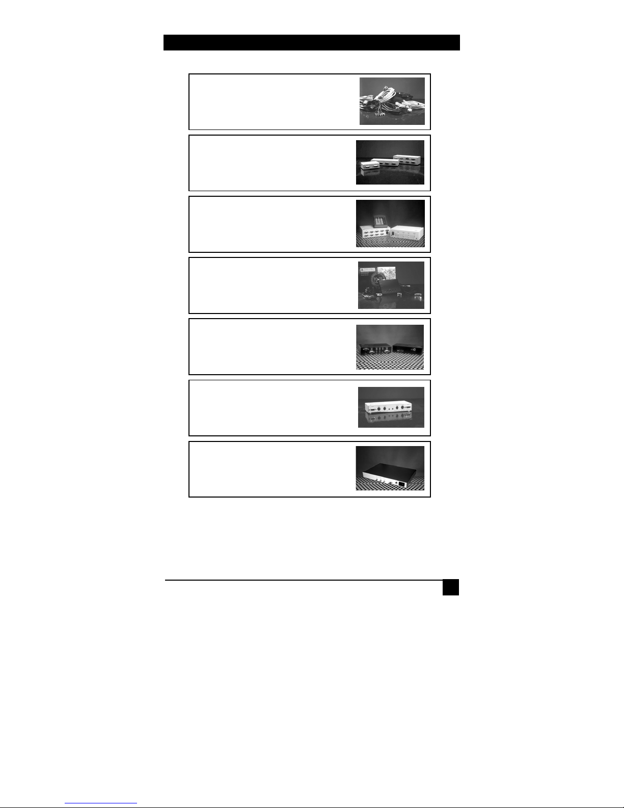
Accessories
Cables: Video, Audio,
DVI, PS/2, Custom, etc
USB,
High Resolution Video
Distribution Amplifiers from 2 to 18 channels
VGA Matrix Switches from 4X4 to 16X16
PC-to-TV Scan Converters
NTSC/PAL-to-VGA
Converter and Switch w
ith
Built-in Audio Switcher
KVM Switches, Extender
Station Doublers
VGA over Fiber-Optic
Transmission Systems
s,
15
Page 18

NOTES
16
Page 19

Page 20
Products Designed and Made in the USA
© Copyright 2003. Hall Research Technologies, Inc.. All rights reserved.
3613 W. Mac Arthur Blvd. Suite 612 , Santa Ana, CA 92704 , Ph: (714)641-6607 , Fax -6698
 Loading...