


-1-
User Guide
Universal Controller HRT 6150
1. Description of the functions
The HRT 6150 is a universal temperature controller with timer function.
It permits the specification of one or two warm phases per day, e.g.
between 6 a.m. and 10 p.m. in the living room or from 6 to 9 a.m. and
5 to 9 p.m. for a bathroom. The temperature is lowered between the
specified times.
The amount by which the controller lowers the target room temperature
is programmed once.
The unit can be used as a
Room temperature controller
The unit controls the room temperature to achieve the desired target
temperature in the range between 5° and 30°C. The current room
temperature is displayed.
Floor temperature controller
The unit controls the floor temperature to achieve the desired target
temperature in the range between 10° and 40°C. The current room
temperature is displayed.
Room temperature controller with monitoring function
The unit controls the room temperature to achieve the desired target
temperature in the range between 5° and 30°C. The current room
temperature is displayed. In addition, the floor temperature is
monitored. The maximum floor temperature is programmed once.
This operating mode can be selected in the setup menu.
The unit is factory-set as a floor temperature controller.
2. Connection / commissioning
ATTENTION: Work on the 230V mains must only be performed by
authorised electricians. When the controller is connected to the mains,
the relevant safety regulations of the VDE and the local utility companies
are to be observed.
L N PE
Heating
Floor temperature sensor
TA (not connected)
TAN
NL L
1
Installation: The temperature controller is to be mounted into a
standard flush-type box Ø 55 mm (acc. to DIN 49073, Part 1). If
additional intermediate terminals are used, we recommend use of a
deep switch box. The connections are to be made in accordance with
the wiring diagram (see above). The connecting cables must be straight
with approx. 5 mm insulation removed; mounting height approx. 1.5 m
above the floor.
Attention: Align the mounting ring on the wallpaper and mount the
controller on the switch box using self-tapping screws for flush-type
boxes. Then fit the frame onto the mounted box.
Attention: Before pressing on the cover, make sure that the internal
sensor (bottom left) points downwards at an angle. The sensor should
not be in contact with the controller housing.
The floor temperature sensor is to be placed in a protective tube lying
centrally between the heating pads and in the same plane as the pads.
The sensor cable must be routed in a separate protective tube (never
together with mains-voltage cables).
Attention: In case of error, the sensor cable may carry mains voltage!
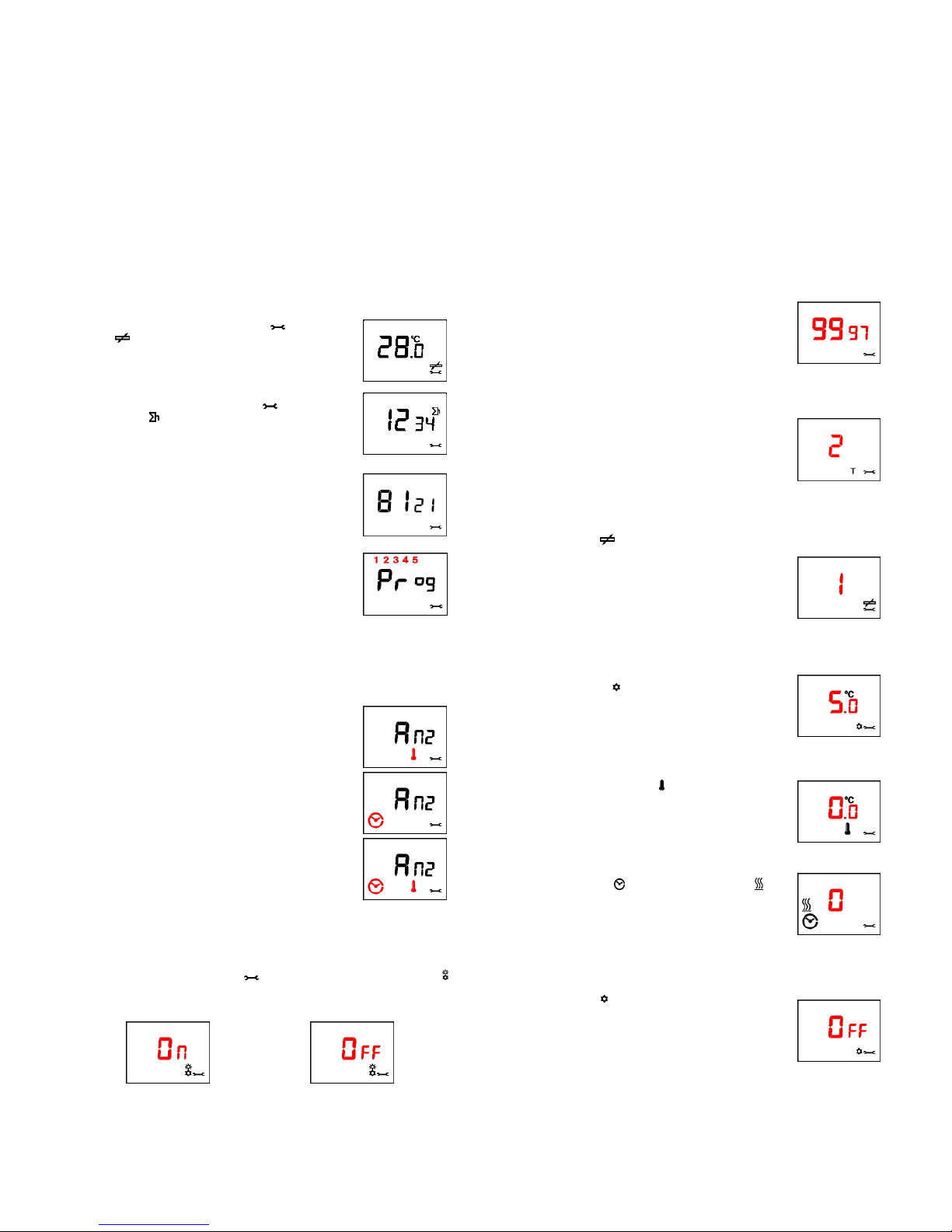
3. Overview of the display
Turning on the unit for the first time:
When the controller is turned on for the first time, all
elements of the display are visible briefly.
After 5 seconds
The current software version of the controller is
displayed.
After 5 seconds
The figures "88:88" are displayed, since time of the
day, date and day of the week are not yet
programmed. Basic programming (Point 6) must be
performed for the unit.
The frost-protection function is active.
4. Standard display
Use the M key to select the operating mode.
▪ AUTOMATIC mode
The controller is active during the specified warm
phases , outside the warm phases , the
temperature is reduced by the specified amount.
▪ MANUAL mode
The controller regulates constantly to the specified
target temperature.
▪ OFF
The controller regulates constantly to the specified
frost protection temperature.
5. Setting the setpoint
Press the + or – key briefly to display the specified setpoint.
(Room temperature controller) (Floor temperature controller)
The desired temperature can then be set by pressing the + and - keys.
The setpoint setting is quit either by pressing the M key or if no key is
pressed 5 seconds. The specified value is accepted automatically.

-2-
6. Basic programming
Pressing the C key briefly opens the controller settings. To switch
between the individual items, use the C key; to make changes, use the
+ and – keys.
The programming can be quit at any time by pressing the M key, but is
also quit automatically if no key is pressed for 10 seconds. The changed
values are accepted automatically.
Press the C key briefly once.
Setting the time
A clock symbol is displayed; use the +/- keys to set
the time.
Press the C key briefly once.
- with automatic setting of daylight saving time
Set the calendar year
A "Y" is displayed;
use the +/- keys to set the calendar year.
Press the C key briefly once.
Set the month / day
A "D" is displayed;
use the +/- keys to set the date.
Large digits: Month / small digits: Day
- without automatic setting of daylight saving time
Set the day of the week
A number for the day of the week is displayed;
use the +/- keys to set the day.
1 = Monday.... 7 = Sunday
Press the C key briefly once.
Automatic daylight saving can be turned on / off in the display menu.
Setting the temperature reduction
A moon and a thermometer symbol are displayed;
use the +/- keys to set the temperature by which the
temperature is to be reduced between the warm
phases.
Setting range: 3° - 15° C
Factory setting: 3°
Press the C key briefly once.
Setting the monitor temperature
(only in the "Room controller with monitoring " mode)
A detector symbol is displayed;
use the +/- keys to set the maximum floor
temperature.
Setting range: 20° ... 40° C
Factory setting: 28°
Press the C key briefly once.
Programming the warm phases
The controller can be operated in either the block or single-day mode. If
block mode is programmed, the same timer program is executed on
each of the working days 1 to 5 (1 = Monday, 2 = Tuesday, etc., see
digits in the top line of the display) and thus only needs to be entered
only once. A different timer program can be entered for the weekends days 6 and 7 (Saturday and Sunday). The possibility to use simply two
blocks saves a great deal of programming work.
Factory setting:
1st warm phase: 6 a.m. - 10 p.m.
2nd warm phase: Not programmed
The individual programming modes are switched in the display menu.
Programming example for the block mode
Start of the 1st warm phase on weekdays:
The days 1 - 5 are shown on the display together with a
sun symbol with index 1.
Press the C key briefly once.
End of the 1st warm phase on weekdays:
The days 1 - 5 are shown on the display together with a
moon symbol with index 1.
Press the C key briefly once.
Start of the 2ndwarm phase on weekdays:
The days 1 - 5 are shown on the display together with a
sun symbol with index 2.
Press the C key briefly once.
End of the 2ndwarm phase on weekdays:
The days 1 - 5 are shown on the display together with a
moon symbol with index 2.
Press the C key briefly once.
Start of the 1stwarm phase on weekends:
The days 6 and 7 are shown on the display together with
a sun symbol with index 1.
Press the C key briefly once.
End of the 1st warm phase on weekends:
The days 6 and 7 are shown on the display together with
a moon symbol with index 1.
Press the C key briefly once.
Start of the 2nd warm phase on weekends:
The days 6 and 7 are shown on the display together with
a sun symbol with index 2.
Press the C key briefly once.
End of the 2nd warm phase on weekends:
The days 6 and 7 are shown on the display together with
a moon symbol with index 2.
Programming example for the single-day mode
Single-day programming is performed in the same way as block
programming. The individual weekdays are shown as numerals in the top
line of the display.
(1 = Monday, 2 = Tuesday, etc.)
.
.
.
.
.
End of basic programming
-3-
7. Display menu
Pressing the C key for 10 seconds opens the display menu. This menu
can be used to display operating states or to change the display
options.
To switch between the individual items, use the C key; to make changes
where necessary, use the + and – keys.
The display menu can be quit at any time by pressing the M key, but is
also quit automatically if no key is pressed for 10 seconds. The changed
values are accepted automatically.
• Display of the floor sensor temperature;
• Display of the operating hours;
• Display of the software version;
• Setting of the programming mode;
• Setting of the display;
• Setting of daylight saving time option.
Press the C key for 10 seconds.
Display of the floor sensor temperature
(only in the case of floor temperature controller and room temperature controller
with monitoring function)
In addition to the setting symbol , the sensor
symbol is displayed; furthermore, the current floor
temperature is displayed.
Press the C key briefly once.
Display of the operating hours
In addition to the setting symbol the operating
hours symbol is displayed and the total number of
hours during which the heating was turned on.
Press the C key briefly once.
Display of the software version
The current software version of the controller is
displayed.
Press the C key briefly once.
Block or single-day programming
"Prog" is displayed. If block programming is set, the
number groups 1 - 5 and 6/7 flash alternately. If
single-day programming is set, all days flash one after
the other.
To change the settings, press the + or – key.
Factory setting: Block programming
Press the C key briefly once.
Display of clock or temperature
“Anz." is displayed. There are 3 different display variants. To change the
settings, press the + or – key.
Display of the room temperature
Display of the current time
The display changes between temperature and time
every 5 seconds (factory setting).
Press the C key briefly once.
Automatic daylight saving time
Daylight saving time is applicable in the EU from the last Sunday in
March (2.00 a.m.) to the last Sunday in October (3.00 a.m.). The
controller adjusts its time automatically at these times.
In addition to the setting symbol the symbol for summer/wintertime
is displayed..
To change the settings, press the + or – key.
Activated (factory setting) Deactivated
Press the C key once to return to the 1st menu item.
End of the display menu
8. Setup menu
Pressing the M key for 10 seconds opens the setup menu. Attention:
The settings in this menu should only be changed by qualified experts, as
they may influence the safety and functioning of the heating system.
To switch between the individual items, use the C key; to make changes
where necessary, use the + and – keys. The setup menu can be quit at
any time by pressing the M key, but is also quit automatically if no key is
pressed for 10 seconds. The changed values are accepted automatically.
• Setting of the controller type
• Setting of the sensor type
• Setting of the frost protection temperature
• Temperature calibration
• Setting of the switching cycle
• Setting of the cooling controller
• Setting of the valve protection
• Setting of the teach-in function
Press the M key for 10 seconds.
Entering the safety code
To be able to change settings in the setup menu, a 4digit safety code must be entered. The code is 9997. If
the correct code is not entered, the controller switches
back to the standard display.
Press the C key once for confirmation.
Setting the controller type
When "T" is displayed, you can set the controller type.
1 = Room temperature controller
2 = Floor temperature controller
3 = Room temperature controller
with floor temperature monitoring
Factory setting: 2 Floor temperature controller
Press the C key once for confirmation.
Setting the sensor type
When sensor symbol is displayed, you can set the sensor type.
1 = 2KΩ Standard HRT sensor
2 = 10KΩ e.g. Busch-Jaeger
3 = 12KΩ e.g. OJ
4 = 15KΩ e.g. DEVI
5 = 33KΩ e.g. Eberle
Factory setting: 1 = (2kΩ Standard HRT sensor)
Press the C key once for confirmation.
Setting the frost protection temperature
When the frost symbol . is displayed, you can set the
frost protection temperature.
Setting range: 3° ... 15° C
Factory setting: 5°C
Press the C key once for confirmation.
Temperature calibration
When the thermometer symbol is displayed, you can
correct the room temperature measurement.
Setting range: -3.0° ... +3.0° C
Factory setting: 0.0°
Press the C key once for confirmation.
Setting the minimum switching cycle
When the clock symbol and the heating symbol are
displayed, you can set the minimum required interval
time between two switching actions.
Setting range: 0 ... 10 minutes
Factory setting: 0 minutes
Press the C key once for confirmation.
Setting cooling controller / actuator open when deenergised
When a star symbol is displayed, you can switch the
switching output of the controller such that a cooling unit
or an actuator which is open when not energised can be
connected to the controller.
Factory setting: OFF
Press the C key once for confirmation.

-4-
Setting the valve protection
When the heating symbol and the hand symbol
are displayed, you can turn on / off the valve
protection. When this function is activated, the output
is activated daily at 10.00 a.m. for 1 minute.
Factory setting: OFF
Press the C key once for confirmation.
Setting the teach-in function
When the heating symbol and the warm-phase
symbols are displayed, you can turn on / off the
teach-in function. If the function is turned on, the
controller automatically calculates the preheating time
required to reach the selected temperature for the
specified warm phase.
Factory setting: OFF
Press the C key briefly once to return to setting of the controller type.
Setting the 2nd temperature reduction
When the moon symbol and the number 2 are
displayed, you can turn on / off the 2nd temperature
reduction function. When this function is activated, you
can set different temperature reductions between the
warm phases.
Factory setting: OFF
Press the C key briefly once to return to setting of the controller type.
End of the setup menu
9. Child safety lock
Press the + and – keys simultaneously for at least 10
seconds. The controller no longer reacts to any
normal key presses. The lock mode can be identified
by the fact that T is displayed.
To cancel the child safety lock, press the + and – keys simultaneously
for at least 10 seconds. The "T" disappears from the display, and all
keys respond once more.
10. Reset
This function is normally not required, except possibly after serious
mains faults.
A reset is initiated by briefly pressing the recessed key. The
programmed values are maintained, but time of day and date or day of
the week must be set anew.
11. Factory settings
Simultaneously pressing the M and C keys for at least 5 seconds
resets the controller to the initial state and restores the factory settings.
The controller is delivered with the following factory settings:
Controller type: 2 (floor temperature controller)
Sensor type: 1 (HRT standard sensor)
Temperature reduction: 3°
Monitor temperature: 28°
Frost protection temperature: 5°
1st warm phase: 6 a.m. - 10 p.m.
2nd warm phase: Not programmed
Programming type: Block programming
Display: Clock + temperature
Automatic daylight saving time: ON
Temperature calibration: 0.0°
Switching cycle: 0 minutes
Cooling controller function: OFF
Valve protection function: OFF
Teach-in function: OFF
2nd temperature reduction OFF
12. Mains power failure
Up to eight hours of mains power failure are compensated. If the power
failure lasts longer, only the clock and date must be set anew; the
remaining settings are maintained.
Any deliberately initiated daily shutdowns (e.g. off-periods of the utility
company) can cause damage to the memory. This is not considered use
according to the intended purpose and results in exclusion of the
warranty.
13. Special function
The controller can be used as a pilot controller (upon request). To this end,
it connects 230V to terminal "TA" (max. load capacity: 0.2A) when in
temperature reduction mode. It is possible to connect satellite controllers
without timer (including bimetal controllers) to the TA terminal; they then
operate simultaneously with the pilot controller in temperature reduction
mode.
14. Troubleshooting
Diagnosis Possible cause / remedy
Heating does not work - Connect / check mains voltage
Display:
- No display Mains power failure
- Er 0 Incorrect input
- Er 1 Room sensor defective
- Er 2 Floor sensor defective
or not connected
- 0.0°C Room temperature 0°C or less
- Switches too early / late Check program settings
- Controller does not react when
temperature changes Checktemperature reduction mode
(only in the case of room temperature controllers with monitoring function)
- (sensor symbol) Monitor temperature reached,
heating mode is turned off
15. Guarantee / warranty
We assume warranty within the framework of the statutory regulations.
Exclusion: The liability for defects does not cover natural wear or
transport damage; likewise not damage due to non-observance of the
installation instructions, inappropriate installation and use not according to
the intended purpose. We assume no liability for the consequences of
improperly performed modifications or repairs. This also pertains to the
provision of single or spare parts.
HRT assumes no liability arising other than directly from the supplied
product, in particular not for indirect, consequential or financial losses.
16. Disposal
At the end of its service life, provide for disposal of the
complete controller, including its cover, in accordance with
the applicable environmental regulations.
17. Technical specifications
Setting range:
Room temperature controller 5° ... 30° C
Floor temperature controller 10° ... 40° C
Floor temperature monitoring 20° ... 40° C
Mains voltage: 230 V ~ ± 10% , 50 Hz
Switching current (max.), approx.: 12 (4) A
Switching capacity: 2.7 kW
Switching temperature difference: 0.7 K
Temperature sensor: NTC to DIN 44574
4 m long
Permissible ambient temperature: -10° ... +40° C
Connecting cables: 2.5 mm²
Degree of protection: IP30
Energy class: VII = 3.5%
HRT Hausregeltechnik GmbH
Otto-Schmerbach-Straße 19
09117 Chemnitz
Tel.: +49(0)371 81 00 1975
Fax: +49(0)371 81 00 1976
info@hausregeltechnik.com
www.hausregeltechnik.com
 Loading...