

HRS SXR User Manual

HARMONIC RESOLUTION SYSTEMS
SXR AUDIO STAND
The Foundation of Great System Performance

Introduction
Thank you for purchasing the Harmonic Resolution Systems SXR Audio Stand.
When used properly, it will give you many years of superior musical or video
signal reproduction.
The SXR Audio Stand significantly reduces the negative impact of structure-borne
noise on your audio or video component performance. Decades of engineering
experience, custom material development, and listening tests are incorporated
into the design of the SXR Audio Stand. This high performance product from
Harmonic Resolution Systems, Inc. will enable your audio/video source and
amplification components to achieve high levels of performance.
The SXR Audio Stand, which includes the HRS Isolation Base as the primary shelf
system, is a perfect match for the HRS Damping Plates and Nimbus Products.
While the SXR Audio Stand and Isolation Bases work to significantly reduce
structure-borne noise, the HRS Damping Plates and Nimbus Products
significantly reduce the harmful effects of air-borne noise and structural
resonance on your components.
Please read this manual completely prior to assembly and use of your SXR Audio
Stand. It contains instructions necessary for proper assembly, use, and care of
this system. Proper care of your SXR Audio Stand will ensure optimum
performance and an aesthetically appealing system.

Safety Instructions
IMPORTANT WARNINGS!
Do not place any tall objects on the top shelf of the SXR Audio Stand. A tall
object is any object with a height that is greater than the length of the isolation
base. A tall object is also any object that has a height greater than its own width
or length. Tall objects must not be placed on top of the SXR Audio Stand for any
reason. The object may become unstable and tip over causing damage to the
component, adjacent objects, or injury to people.
Never lift or move the SXR Audio Stand with the shelves (Isolation Bases)
installed. You should always move the SXR Audio Stand frame to its final
location prior to loading shelves and components. Moving the SXR Audio Stand
frame with the isolation bases installed (with or without equipment) can
permanently damage the frame system or cause the shelves to fall out of the rack
resulting in potential damage or injury. Always take the time to remove all of the
equipment and shelves to relocate the SXR Audio Stand.
Do not lift the Isolation Base (shelf) by the inner plate (M3 model) or the external
feet attached to the bottom of the rectangular frame. Always lift or move the
isolation base with the inner plate facing up and the external support feet facing
down (same orientation as when used to support your component). Always
follow these handling instructions to prevent personal injury or damage to the
unit.

Set-Up Instructions
The SXR Audio Stand consists of a frame structure and the isolation bases that
support each component. The components required to assemble the frame are
shipped in one or more boxes. The number of boxes depends on the system size.
Each box containing parts for the frame will be marked with the model number
starting with SXR. All the wrenches required to put the frame together are
included with the shipment.
Work Surface - Prior to unpacking any material, locate a very strong and very
stable work surface (capable of supporting 250 lb. load) or area on the floor that
will give you a very soft scratch resistant work area that is at three feet by three
feet in size. The more space you have the better, as it will give you room to move
around the frame to complete assembly. It is important that the area be free of all
dirt, screws or small pebbles, and that it is covered with a clean soft protective
blanket of same size that will prevent damage to high quality finish on the frame.
Unpacking Assembly Hardware - Remove all the contents from all the boxes
marked with SXR model number. Place all the hardware on a table adjacent to
your selected work surface and remove all the wrapping material. Be careful not
to drop or allow the anodized aluminum parts to contact each other as they may
scratch the surface. Do not stack the parts on top of each other once they are
removed from the protective packaging material. To make assembly easier group
identical parts together in an organized manner. Make sure all tubes are
matched for proper (same) length.
This audio stand will be assembled upside down. Depending on what frame
configuration you have purchased there will be a number of Support Braces that
have threaded studs already attached. Do not try to remove these threaded studs
as they are attached to the frame. These Support Braces with threads will be the
top of the audio stand.
Note:
Depending on how your SXR audio stand frame was shipped it may arrive
partially assembled. This means Steps 1 and 2 would have been completed so the
Support Braces and Cross Braces will already be attached. If your SXR was
partially assembled, complete assembly by skipping Steps 1 and 2 and referring to
the instructions at Step 3.
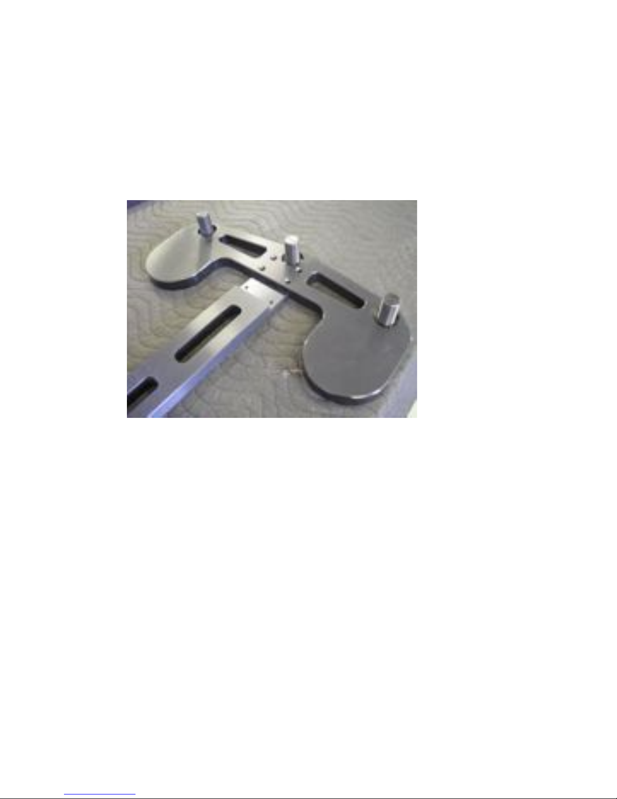
Step 1. Obtain one of the Support Braces with threaded studs. Place it upside
down on the work surface with threads facing up (see photo 1). Obtain a Cross
Brace and flip this over as well as shown in Photo 1 below. Slide one of the ends
of the Cross Brace into the area below the countersunk holes on the Support
Brace. The countersunk holes of the Support Brace should line up with the
threaded holes of the Cross Brace.
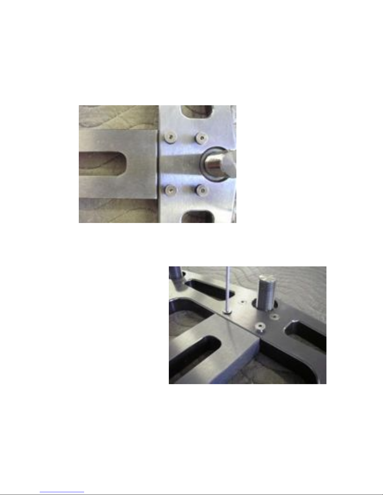
Step 2. Using the 5/32” T- wrench or ratchet wrench (supplied with stand)
attach the Cross Brace to the Support Brace with the 1/4” - 20 x 3/4” flat head
cap screws (also supplied with the unit). Before tightening screw fully be sure
that the Cross Brace and Support Brace are completely perpendicular to each
other as shown in Photo 2. Tighten screws (shown in Photo 3) until the screws
stop turning and the top of wrench handle twists an additional 1/16 and 1/8 of a
rotation relative to the bolt. This will give you proper torque on the assembly.
Repeat steps 1 and 2 for the opposite side of the Cross Brace with again checking
that the two parts are perpendicular to each other (minor adjustments can be
made prior to torque of the bolts).
Note: If assembling a double or triple wide SXR the Center Brace will be
installed to the other side of the Cross Brace.
Photo 1
Note: Be very careful not to cross-thread the threaded struts or fasteners. They
should thread in very easily. If it does not, back it out and start it in again (repeat
as necessary). Never force a threaded connection. If it does not thread on easily
then there is something wrong and you should contact HRS or your local retail
facility for assistance. Apply proper torque when instructed and after all the
fasteners at each step are in place.
Photo 2
Photo 3
 Loading...