

HRS QR-P18 User manual
Rectangular, High-Pin-Count Rack/Panel
Insulation Displacement Connectors (IDC)
QR/P18 Series
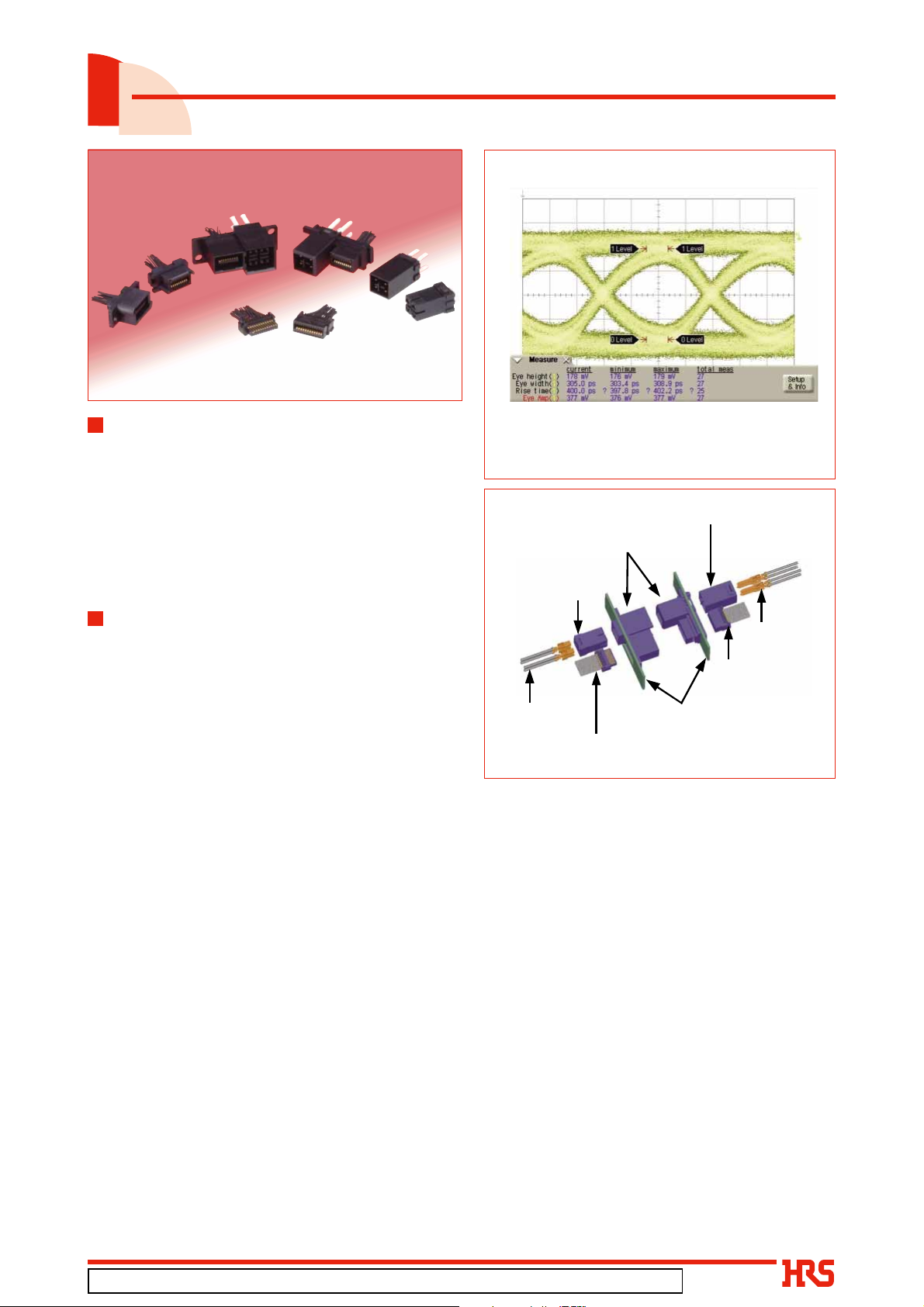
2.5Gbps Eye Diagram
Overview
The QR/P18 Series of miniature rack/panel connectors
2.5Gbps
AWG#28 2m
is designed for the complete segmentation of the
structure of the external holder/terminal units of the
well-received QR/P Series of plug-in rectangular rack/
panel connectors; furthermore, the subsequent
insertion of the harnessed terminal unit affords a more
efficient harness mounting task. These connectors are
configured with 12, 18, or 24 pos.(IDC) in the signal
line, and 4 pos.(crimp) in the power line.
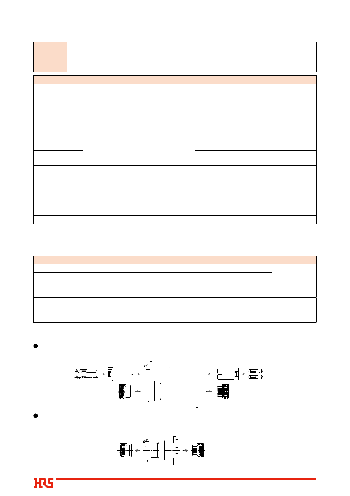
Power supply contact
female unit
Features
1. Completely separated structure of the
external holder/terminal unit
In order to improve the harness procedures, the
connectors are designed for the complete
segmentation of the external holder and the signal/
power supply unit, and inserting the harnessed
contacts aims to improve the workability of the power
supply/signal line harness as well as the mounting to
the set.
2. Signal unit
The signal unit uses the highly reliable insulation
displacement connection method. (The wire is AWG
#26 and the insulation outter diameter is 0.88mm.)
The insulation displacement procedure can now be
used by attaching a special applicator to a
Apr.1.2021Copyright2021HIROSEELECTRICCO.,LTD.AllRightsReserved.
commercially available automatic insulation
displacement machine, or a manual press tool can
also be selected.
3. Power supply
The power supply terminals permit the use of a
crimp harness using wire of AWG#16 to 18 (and
insulation outside diameter of 2.1 to 2.2mm), and
can accommodate a maximum of 12 A.
4. Sequential mating structure
Two sequential contacts in the signal male unit and
one sequential contact in the power supply female unit
are provided for safety operation.
5. Panel installation
Installation to a panel uses a single-action method
on the anchored side and a floating screw structure
on the floating side which permits smooth insertion
and disconnection without forcing.
Power supply
female contacts
External holder
Signal contact
male unit
Scale
X : 100psec/div
Y : 100V/div
Power supply contact male unit
Power supply
male contacts
Signal contact
female unit
Panel
Fig.1
Fig.2
In cases where the application will demand a high level of reliability, such as automotive,
please contact a company representative for further information.
2021.2e
1
QR/P18 Series●Rectangular, High-Pin-Count Rack/Panel Insulation Displacement Connectors (IDC)
Product Specifi cations
■
Voltage rating
Ratings
Current rating
Item Specifi cation Conditions
Contact resistance
1.
Insulation resistance
2.
Withstanding Voltage
3.
4. Durability
(mating / un-mating)
5. Vibration
6. Shock
7. Temperature cycle
8. Humidity
(Steady state)
9. Salt mist No HEAVY corrosions. 5% salt water solution for 48 hours
Note1 : Includes temperature rise caused by current fl ow.
Note2 : Excludes wire conductor resistance.
50mø max. (Signal contacts) (Note 2)
10mø max. (Power contacts) (Note 2)
1000Mø min. (Signal contacts)
5000Mø min. (Power contacts)
No fl ashover or insulation breakdown. 500V AC / 1 minute
Contact resistance : 70mø max. (Signal contacts)
20mø max. (Power contacts)
No electrical discontinuity of 10µs or more.
No damage, cracks or parts dislocation.
Contact resistance : 70mø max. (Signal contacts)
20mø max. (Power contacts)
No damage, cracks or parts dislocation.
Insulation resistance:
100Mø min. (Signal contacts, state)
3000Mø min. (Power contacts, state)
No damage, cracks or parts dislocation.
125V AC (Signal contacts)
300V AC (Power contacts)
1A (Signal contacts)
12A (Power contacts)
Operating temperature range
100mA MAX (DC or 1000Hz)
500V DC
3000 cycles
Frequency: 10 to 55 Hz, single amplitude of 0.75mm,
2 hours in each of the 3 axis.
Acceleration of 490 m/s2, 11 ms duration, sine halfwave waveform, 3 cycles in each of the 3 axis
Temperature : -55ç ➝ +5 to +35ç ➝ +105ç ➝ +5ç to +35ç
Time : 30 ➝ 5 ➝ 30 ➝ 5 (Minutes)
5 cycles
96 hours at 40ç and RH 90% to 95%
-40°C to +105°C
(Note 1)
Materials
■
Product Components Material Finish Remarks
External holder Insulator PBT
Insulator PA
Signal contact unit
Power contact unit Insulator PBT
Power supply contacts
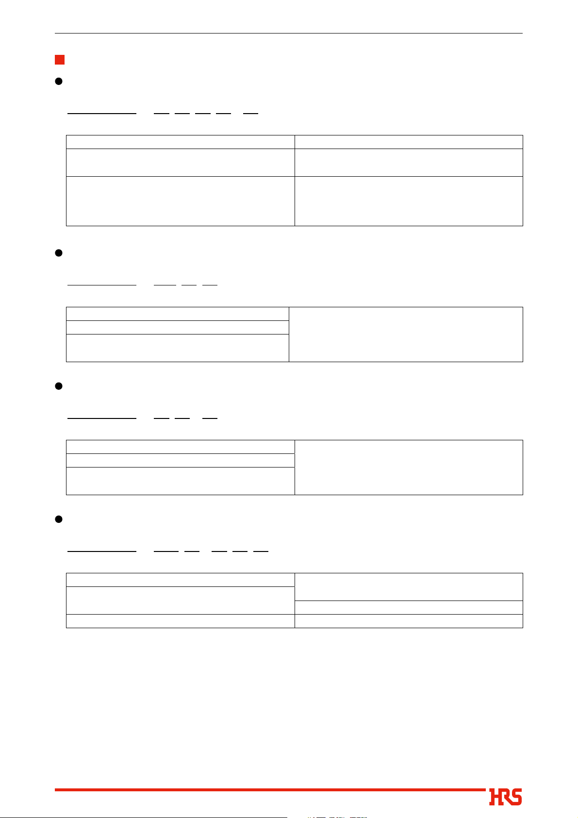
Function Diagram
■
Apr.1.2021Copyright2021HIROSEELECTRICCO.,LTD.AllRightsReserved.
Power supply/signal combination type
QR/P17-PCA-*11(70) QR/P17-SCA-*11(70)
Female contacts
Male contacts
Female contacts
Male contacts
QR/P18-4P-C QR/P18-4S-C
Phosphor bronze Gold plated
Copper alloy Gold plated + Tin plated
QR/P18-S*4P-* QR/P18-P*4S
Signal type
−−−−−
−−−−−
−−−−−
QR/P18-*P*QR/P18-*S*
UL94V-0
−−−−−
−−−−−
UL94V-0
−−−−−
−−−−−
QR/P18-P*QR/P18-S*-*
QR/P18-*S*
QR/P18-*P*
2
QR/P18 Series●Rectangular, High-Pin-Count Rack/Panel Insulation Displacement Connectors (IDC)
Product Number Structure
External holder
QR / P18 - S A 4 P - A
❶ ❷❸❹❺ ❻
Series name
q
Signal contact type S : Female contact
w
P : Male contact
Number of signal contact of external holder
e
A : 12 pos. (Contact pitch 1.5mm)
B : 18 pos. (Contact pitch 1.5mm)
C : 24 pos. (Contact pitch 1.5mm)
Signal Unit
QR / P18 - 12 S A
❶❷❸❹
Series name
q
Number of signal contact
w
Signal contact type S : Female contact
e
P : Male contact
Power Unit
QR / P18 - 4 P - C
❶❷❸❹
Number of power contact
r
Power contact type S : Female contact
t
P : Male contact
Applicable panel thickness
y
A : 2mm
B : 1.5mm
Signal unit size
r
A : 12 pos. (Contact pitch 1.5mm)
B : 18 pos. (Contact pitch 1.5mm)
C : 24 pos. (Contact pitch 1.5mm)
Series name
q
Number of power contact
w
Power contact type S : Female contact
e
P : Male contact
Connector type C : Crimp housing
r
Power contact
QR / P17 - PC A - 1 1 1
❶❷❸❹❺❻
Apr.1.2021Copyright2021HIROSEELECTRICCO.,LTD.AllRightsReserved.
Series name
q
Power contact type PC : Male crimp contact
w
SC : Female crimp contact
Applicable wire style A : UL1015
e
Packaging 1 : Pack packaging
r
2 : Reel packaging
Applicable wire 1 : AWG#16 to 18
t
Contact plating 1 : Gold plated
y
3
 Loading...