

HRS MXR User Manual

HARMONIC RESOLUTION SYSTEMS
MXR AUDIO STAND
The Foundation of Great System Performance

Introduction
Thank you for purchasing the Harmonic Resolution Systems MXR Audio Stand.
When used properly, it will give you many years of superior musical or video
signal reproduction.
The MXR Audio Stand significantly reduces the negative impact of structureborne noise on your audio or video component performance. Decades of
engineering experience, custom material development, and listening tests are
incorporated into the design of the MXR Audio Stand. This reference level
product from Harmonic Resolution Systems, Inc. will enable your audio/video
source and amplification components to achieve peak performance.
The MXR Audio Stand, which includes the HRS Isolation Base as the primary
shelf system, is a perfect match for the HRS Damping Plates and Nimbus
Products. While the MXR Audio Stand and Isolation Bases work to significantly
reduce structure-borne noise, the HRS Damping Plates and Nimbus Products
significantly reduce the harmful effects of air-borne noise and structural
resonance on your components.
Please read this manual completely prior to assembly and use of your MXR Audio
Stand. It contains instructions necessary for proper assembly, use, and care of
this system. Proper care of your MXR Audio Stand will ensure optimum
performance and an aesthetically appealing.

Safety Instructions
IMPORTANT WARNINGS!
Do not place any tall objects on the top shelf of the MXR Audio Stand. A tall
object is any object with a height that is greater than the length of the isolation
base. A tall object is also any object that has a height greater than its own width
or length. Tall objects must not be placed on top of the MXR Audio Stand for any
reason. The object may become unstable and tip over causing damage to the
component, adjacent objects, or injury to people.
Never lift or move the MXR Audio Stand with the shelves (M3 Isolation Bases)
installed. You should always move the MXR Audio Stand frame to its final
location prior to loading shelves and components. Moving the MXR Audio Stand
frame with the isolation bases installed (with or without equipment) can
permanently damage the systems adjustable feet or cause the shelves to fall out of
the rack resulting in potential damage or injury. Always take the time to remove
all of the equipment and shelves to relocate the MXR Audio Stand.
Do not lift the M3 Isolation Base (shelf) by the inner plate or the external feet
attached to the bottom of the rectangular frame. Always lift or move the isolation
base with the inner plate facing up and the external support feet facing down
(same orientation as when used to support your component). Always follow
these handling instructions to prevent personal injury or damage to the unit.
Set-Up Instructions
The MXR Audio Stand consists of a frame structure and the isolation bases that
support each component. The standard three and four shelf frame structures
come in three boxes. Each box will be marked with the model number starting
with MXR. There are two longer boxes that contain the left and right vertical
panels. The third box contains the panel brace system, the isolation base support
brackets, the adjustable rack feet, screws, and wrenches required to complete the
assembly process. The only tools not provided for assembly are:
1. Adjustable wrench - to lock the feet after leveling the frame
2. Philips Head Screwdriver - for unpacking crates (electric drive
recommended)
3. Level - 24" minimum length or equivalent
Work Surface - Prior to unpacking any material, locate a very strong and very
stable work surface (capable of supporting 250 lb. load) or area on the floor that
will give you a very soft scratch resistant work area that is at least three feet by
six feet in size. The more space you have the better, as it will give you room to
move around the frame to complete assembly. It is important that the area be free
of all dirt, screws or small pebbles, and that it is covered with a clean soft
protective blanket (min size 24" x 45") that will prevent damage to the relatively
soft external skin of the vertical panels.
Unpacking Assembly Hardware - Remove all the contents from the smaller
cardboard box containing the hardware required to assemble the frame. Place
them on a table adjacent to your selected work surface and remove all the
wrapping material. Be careful not to drop or allow the anodized aluminum parts
to contact each other as they may scratch the surface. Do not stack the parts on
top of each other once they are removed from the protective packaging material.
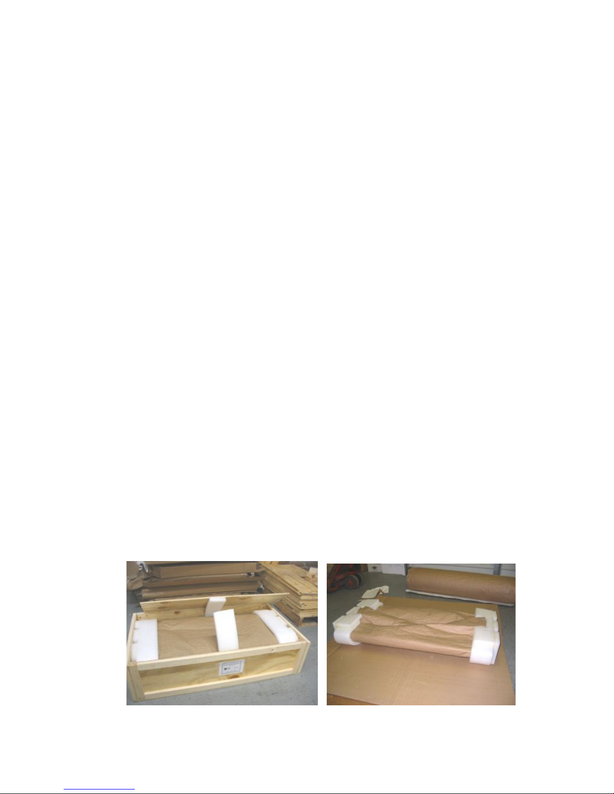
Unpacking Vertical Panels - Unpack the vertical panel by removing the top
surface of the crate (see Photo 1). This surface will be marked for clarity and you
will need a Philips head screwdriver (manual or electric) to remove the cover.
Photo 1 Photo 2
Lift the panel out of the crate by lifting vertically at each end (see Photo 2). Move
the panel and packing material directly to your damage free work surface. Once
at the work surface, remove and save the two fitted foam end support cushions.
Then open the protective paper covering the panel to expose the unit for
assembly. Saving all the packing material is critical to secure transportation of
the frame in the future. Shipping or moving the panel by any other means may
expose the unit to permanent damage.
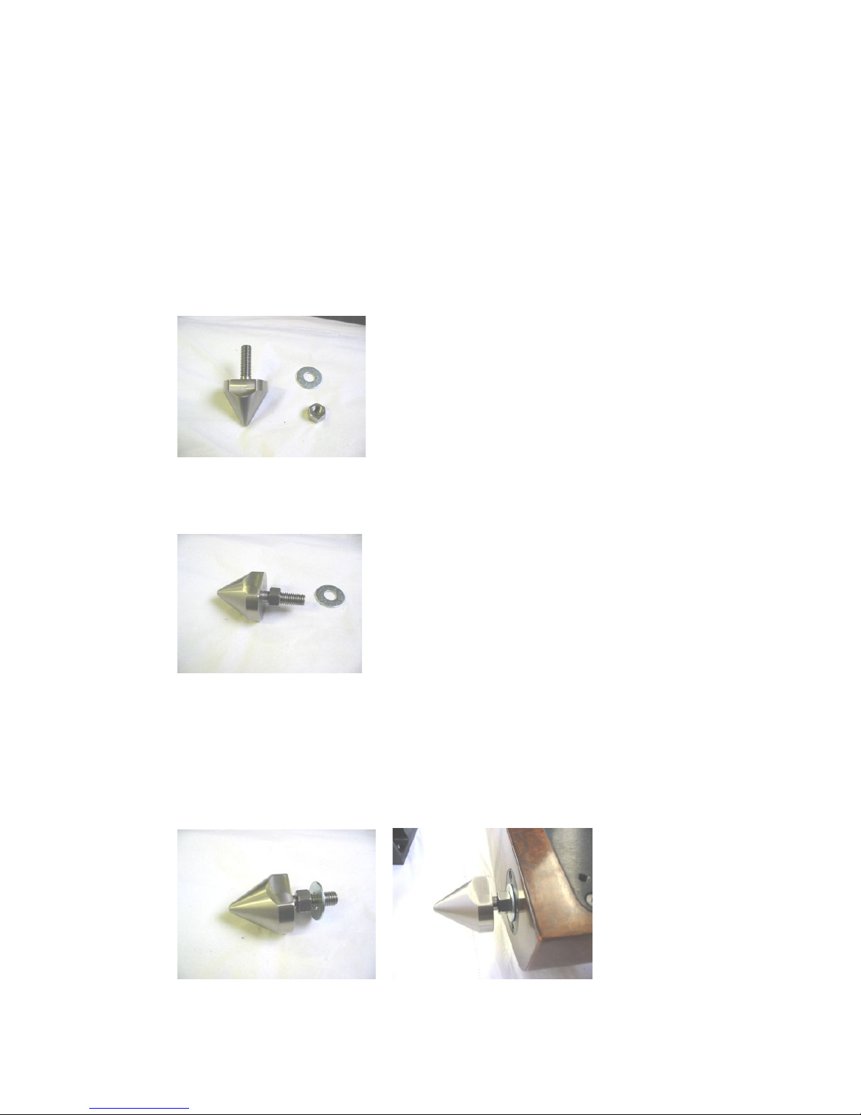
Installation of Adjustable Foot System - Unwrap two of the four feet supplied
with the unit. Remove the screw and washer from each of the feet (see Photo 3).
Photo 3
Hands tighten the nut all the way down on each individual foot. Then back the
nut off one half rotation (see Photo 4).
Photo 4
Place the supplied washer on top of the nut and then screw each of the feet into
the threaded inserts on the bottom of the first vertical panel (see Photo 5 & 6).
The feet should be threaded into the insert until the washer/nut come in contact
with the vertical panel threaded insert. (This ensures maximum engagement
between the insert and the foot). Repeat this procedure and install the second foot
to the bottom of the first vertical panel.
Photo 5 Photo 6
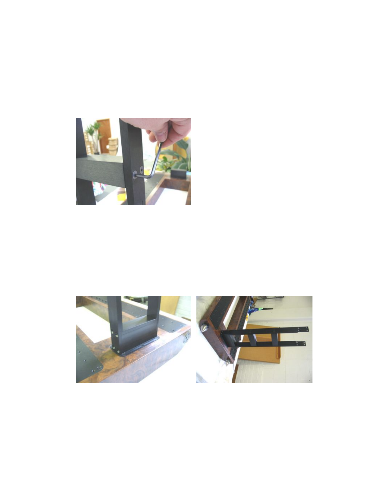
Panel Brace Installation - You are now ready to attach the primary brace system
to the panel. There are two braces that hold the two end panels together to form
the primary MXR Frame Structure. There are two rectangular spacers attached
to each brace system when it is shipped that need to be loosened to complete
assembly. Simply take the T-wrench or Allen wrench supplied with the MXR and
loosen (counter clockwise) each of the eight nuts on the brace assembly (see
Photo 7). You do not want to have lots of play in the assembly, you just want to
break the torque on each nut so that the brace can be properly located.
Photo 7
The HRS logo is machined into the center of each brace. Locate the HRS logo on
the brace and orient it so that when the stand is upright on its feet, the logo will
be in correct orientation. There are two steps at each end of the brace sub
assembly that fit precisely over the attachment block on the panel. Slowly lower
the brace assembly onto the block until the steps in the brace contact the block
(see Photo 8 and Photo 9). Attach at least one of the 1/4-20 x 3/4" screws to the
brace assembly (see Photo 10) prior to removing your hand from the assembly to
insure it stays in place. It is very important that the 3/4" long screws are used at
this location to obtain proper thread engagement.
Photo 8 Photo 9
 Loading...