

Page 1
C2
Compact Flash©Card Connectors
MI20/21 Series
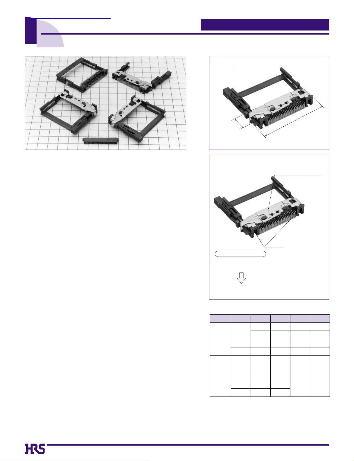
1. Compact design occupies minimum space
Connectors are designed with small width and depth for
miniaturization and the foot print on the board has been
made smaller. (See (a) to the right)
2. Supplied with ground terminals
The MI21 Series are furnished with ground terminals.
3. Card ejection mechanism
Two point ejection mechanism to assure even card
ejection.
4. Designed and packaged for board placement
with automatic equipment
Headers are designed with a pick up area to accommodate
the pick-and -place nozzles of automatic mounting
machines. (Patents pending)
Receptacles are designed to be mounted on top the board,
and automatic mounting is possibble on the specified
board.
5. Card ejection mechanism
Available in several termination and mouting styles, with
and without ejection mechanism, with and without standoffs.
6. Rich variations
A rich assortment of variations allows selection of a type to suit
the specific card and the equipment to which it will be installed.
(1)Suitable cards: Type I , type I/II .
(2)Eject button: None, right , left
(3)Standoff: 0 mm, 2.2 mm
(4)Board mounting type: Standard , reverse
■Features
PDA, digital still cameras, etc.
■Applications
Complies with Compact Flash Association
7.0
51.75
(b)Suitable for automatic mounting
(a)Space-saving design
MI20
Series
Mounting
offset Ejector Cards
----
Built-in nuts
YES
YES
Ø(None)
Type1or2
Type1or2
Type1
Type1
None None
None
None
Right
Left
Right
Left
None
None
None
2.2 mm
2.2 mm
2.2 mm
Standard
Standard
Reverse
Reverse
MI21
Note 1: Hexagonal nuts (M2∞0.4) are required.
●Producut variation
查询MI20-50PDR-SF供应商
Automatic equipment
pick up area.
HRS Product Feature
Fixed fittings make
slider immobile.
Construction facilitates
pick-and-place process.
Fixed
Page 2
C3
8. Resistance to Soldering
heat
1,000 M ohms min.
No flashover or insulation breakdown.
40 m ohms max. (initial value) (Note 3)
No electrical discontinuity of 100ns or more
Insulation resistance of 100 M ohms min.
No deformation of components affecting performance.
6. Temperature cycle
7. Durability
(Insertion/withdrawal)
■Materials
Series name: MI
Series No.
20: for type I cards (
✽
)
21: for type I and II cards
Stand off type
Blank : None
A : 2.2 mm
Number of contacts: 50
Connector type
PD: Header
Board mounting type
Blank : Standard
R : Reverse
Contact type
SF: SMT
Eject button position
EJR : Right button
EJL : Left button
Blank : None
Built-in nut type
(31): With built-in nuts
Blank: Standard product
1
2
3
4
5
6
7
8
9
500 V DC
500 V AC / 1 minute
1 mA
96 hours at temperature of 40
ç
and humidity of 90% to 95%
Temperature: -55çfor 30 min. --> +5 to 35çwithin 5 min.
85
ç
for 30 min. --> +5 to 35çwithin 5 min. for 5 cycles
Frequency: 10 to 2000 Hz, full amplitude of 1.52 mm or
acceleration of 147 m/s
2
(peak), 4 hours in each of the 3 directions.
10000 cycles at 400 to 600 cycles per hour
Reflow: At the recommended temperature profile
Manual soldering: 300ç for 3 seconds
4. Vibration
5. Humidity (Steady state)
1. Insulation resistance
2.
Withstanding voltage
3. Contact resistance
■ Product Specifications
Item Specification Conditions
Note 1: Includes temperature rise caused by current flow.
Note 2:
The term "storage" refers to products stored for long period of time prior to mounting and use. Operating Temperature Range
and Humidity range covers non- conducting condition of installed connectors in storage, shipment or during transportation.
Note 3: This does not include the resistance of the conductor .
(
✽
) Can accommodate type II cards only when standard mounting is
used and stand off is 0 mm.
Rating
Current rating
Voltage rating
0.5 A
125 V AC
Operating temperature range
Operating humidity range
-55 to +85ç(Note 1)
Relative humidity 95% or less
(No condensation)
Storage temperature range
Storage humidity range
-10 to +60ç
-40 to 70%
Insulation resistance of 100 M ohms min.
Change of contact resistance from initial value is
20 m ohms max.
Item Part Material Finish Remarks
Receptacle
Insulator PPS Color:Black UL94V-0
---------------
UL94V-0
Applied to eject mechanism
---------------
Applied to MI21 series
---------------
---------------
Contact Area : Gold plating
Lead Area : Solder plating
Color:Black
---------------
---------------
---------------
Solder plating
Contact Area : Gold plating
Termination Area: Solder plating
Phosphor bronze
PPS
Brass
Stainless steel
Stainless steel
Steel
Brass
Contacts
Insulator
Contacts
Metal fitting
Eject fitting
Ground clip
Nut
Header
MI 20 - 50 RD - SF
1 2 3 4 5
●Receptacles
MI 20 A - 50 PD R - SF - EJR (31)
1 2 3 4 5 6 7 8 9
●Headers
■Ordering Information
Series name: MI
Series No.: 20
Number of contacts: 50
Connector type RD: Receptacle
Contact form SF: SMT
1
2
3
4
5
Page 3
C4
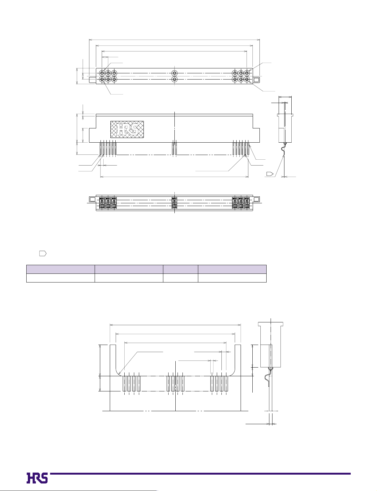
■Receptacle
BPCB mounting pattern
Note The coplanarity of the conductor is 0.1 mm Max.1
CL No.
640-7001-0MI20-50RD-SF 50 Tray
Part Number
Number of Contacts
Packaging
3.3
6
2.6
1.27
0.5
3
No.50
No.25
1.27
No.25
No.50
0.635
35.86
32.97
30.48
31.115
(t0.08∞w0.3)
-2
No.1
No.26
No.1
No.26
(offset)
1
2.7
0.2
0.05
1
(4.2)
2-R1max
(35)
+0.1
33.4
+0
31.115±0.05
0.635±0.03
50-0.4±0.03
A
3max
2min
+0.2
+0
1.2
(Recommended board thickness=0.4)
Page 4
C5
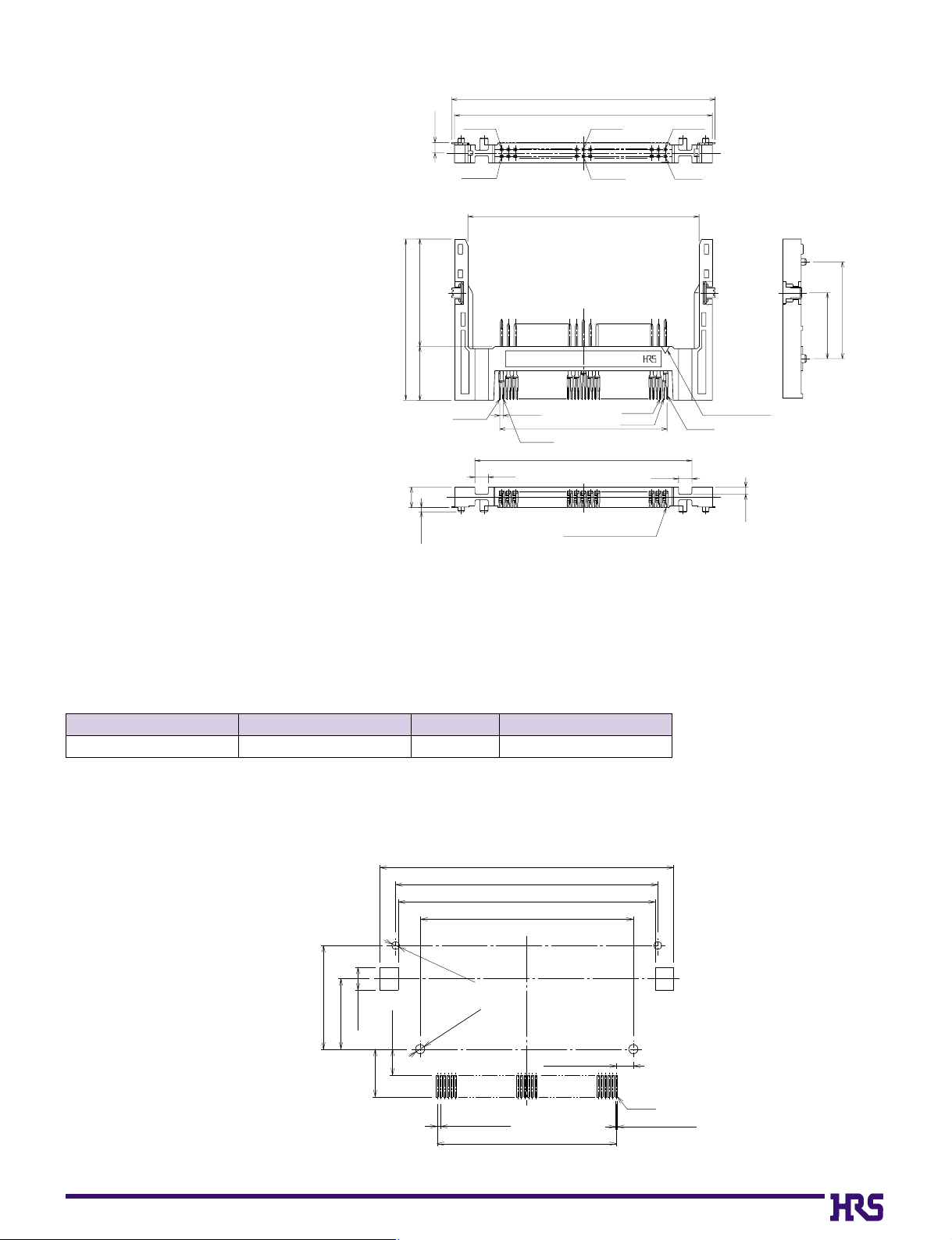
BPCB mounting pattern
48
43.03
30
40.4
2.5
2.5
1.95
(20)(10)
No.1
No.2
No.26
No.50
No.25
12.25
18
3.8
t : 0.25 ∞ w : 0.25
49
Polartiy mark
No.1No.13
No.25
1.35
31.115
0.635
No.26No.38
No.50
MI20--50PD
(0.8)
●Eject button : None
●Offset : None
●Mounting style : Standard mounting
■Headers for Type I or II Cards
Note 1: Coplanarity of all surface mount terminals and components is 0.1.
Note 2: Dimensions in parentheses ( ) are reference dimensions.
CL No.
640-7002-2MI20-50PD-SF 50 Tray
Part Number
Number of Contacts
Packaging
51±0.1
45.5±0.05
44.6±0.1
37±0.05
18±0.05
12.25±0.1
4±0.05
8.25min
4.5max
2-Ø1.4
2-Ø1.6
0.634±0.03
+0.1
+0
+0
+0.1
31.115±0.05
2.9425±0.05
No.1
50-0.4±0.03
Page 5
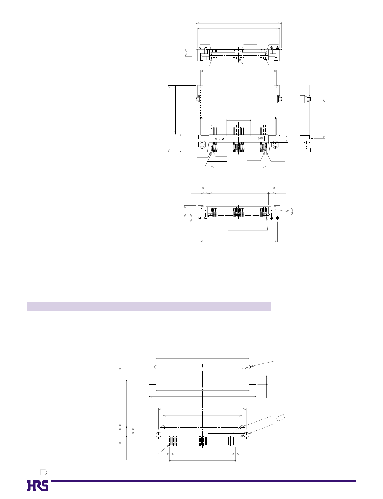
C6
Note 1: Coplanarity of all surface mount terminals and components is 0.1.
Note 2: Dimensions in parentheses ( ) are reference dimensions.
CL No.
640-7003-5MI20A-50PDR-SF 50 Tray
Part Number
Number of Contacts
Packaging
●Eject button : None
●Offset : 2.2 mm
●Mounting style : Reverse mounting
■Headers for Type I Cards
48.3
46.3
No.1
No.13
No.25
No.50
No.38
No.26
4.15
37.9
(27.9)
(10)
6.6
(0.15)
(1)
43.03
(17.2)
No.50
No.25
No.1
No.26
31.115
42.3
33.7
44
t : 0.25∞w : 0.25
(4.3)(4.3)
No.2
0.635
(4.5)
22.25
BPCB mounting pattern
Note The holes
(2-Ø2.4 )
illustrated in the figure are only required when screws are used for fastening.
1
+0.1
0
44±0.05
28.5±0.05
22.25±0.1
8.25min
4.5max
3.5±0.05
No.1
0.635±0.03
43.9±0.1
50.3±0.1
41.3±0.05
31.115±0.05
37±0.05
2.9425±0.05
50-0.4±0.03
2-Ø1.3
2-Ø1.6
2-Ø2.4
+0.1
+0
4±0.1
+0.1
+0
+0.1
+0
1
Page 6
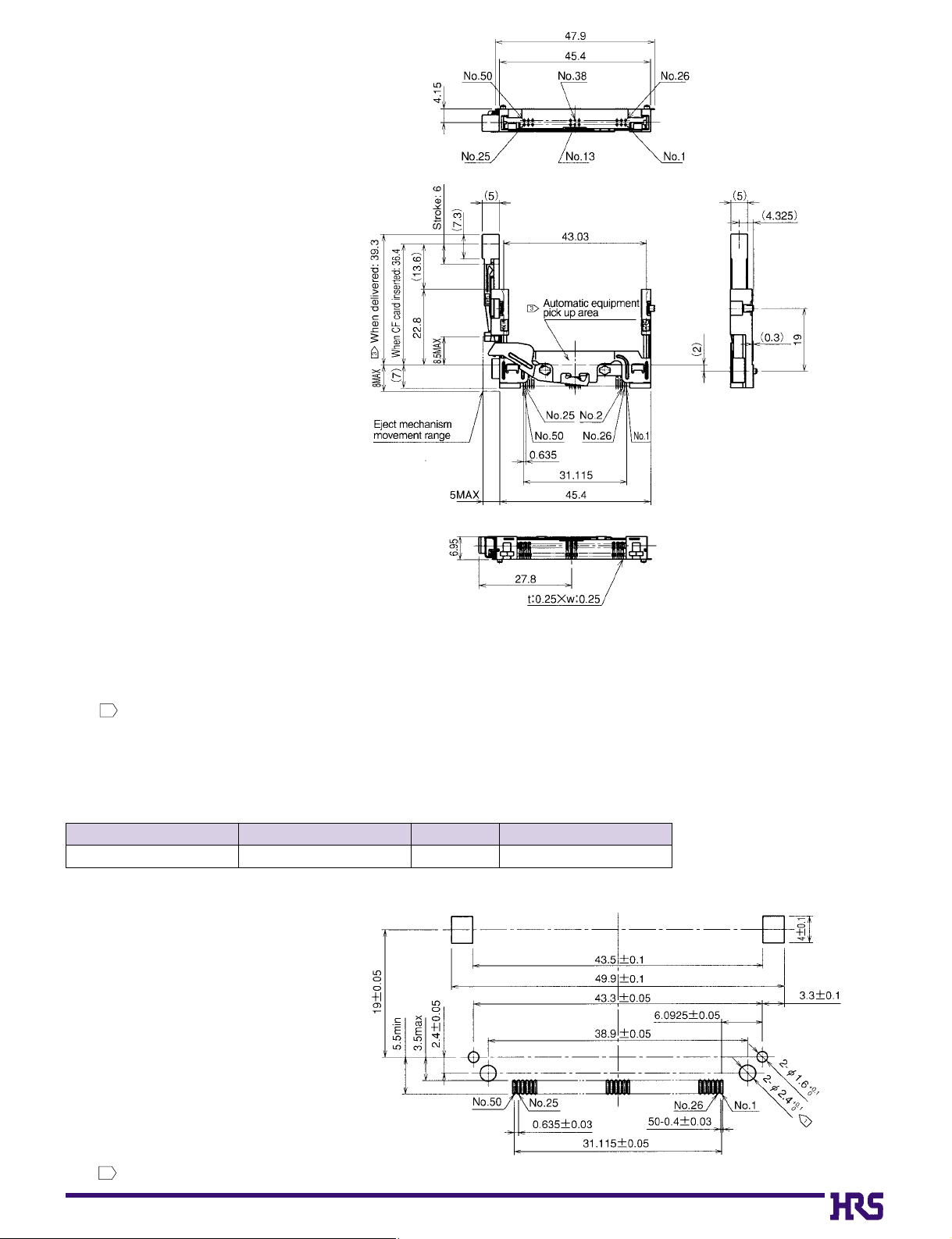
C7
●Eject button : Right button
●Offset : 2.2 mm
●Mounting style : Standard mounting
■Headers for Type I Cards
BPCB mounting pattern
Note 1:
The amount of card and button protrusion from the connector after mating is 13.6 mm.
Note 2:
The dimensions of mating portion of this product comply with CFA standards.
Note 3:
This product can be automatically mounted. The suction surface for automatic mounting is positioned as illustrated in the figure.
This part is fixed in the initial condition, but released with a single operation of the ejector.
(Amount of actual card ejection: 3.5 mm)
Note 4:
The coplanarity (degree of flatness) of the SMT lead tip portion and the reinforced fitting mounting end face is to be 0.1 maximum.
Note 5:
Dimensions in parentheses ( ) are to be regarded as reference dimensions.
3
CL No.
640-7004-8MI20A-50PD-SF-EJR 50 Tray
Part Number
Number of Contacts
Packaging
Note The holes
(2-Ø2.4 )
illustrated in the figure are only required when screws are used for fastening.
1
+0.1
0
Page 7
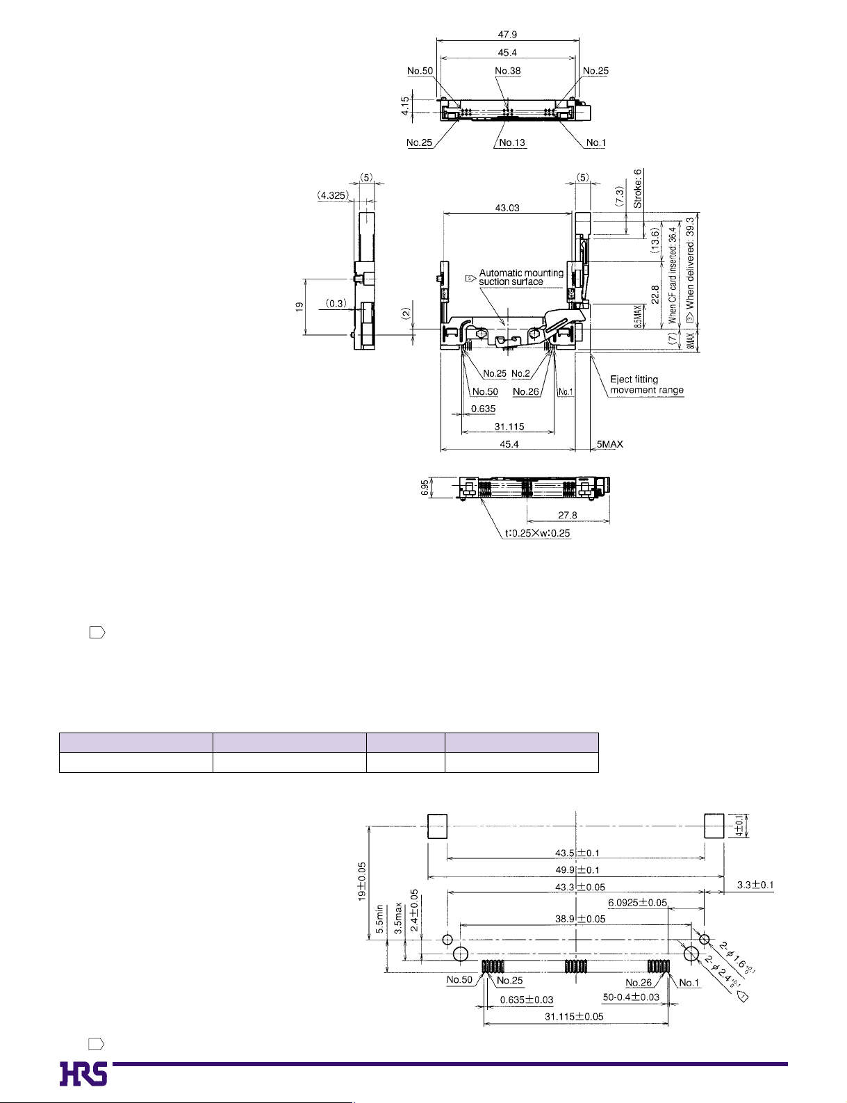
C8
●Eject button : Left side
●Offset : 2.2 mm
●Mounting style : Standard mounting
■Headers for Type I Cards
BPCB mounting pattern
Note 1:
The amount of card and button protrusion from the connector after mating is 13.6 mm.
Note 2:
The dimensions of mating portion of this product comply with CFA standards.
Note 3:
This product can be automatically mounted. The suction surface for automatic mounting is positioned as illustrated in the figure.
This part is fixed in the initial condition, but released with a single operation of the ejector.
(Amount of actual card ejection: 3.5 mm)
Note 4:
The coplanarity (degree of flatness) of the SMT lead tip portion and the reinforced fitting mounting end face is to be 0.1 maximum.
Note 5:
Dimensions in parentheses ( ) are to be regarded as reference dimensions.
3
CL No.
640-7005-0MI20A-50PD-SF-EJL 50 Tray
Part Number
Number of Contacts
Packaging
Note The holes
(2-Ø2.4 )
illustrated in the figure are only required when screws are used for fastening.
1
+0.1
0
Page 8
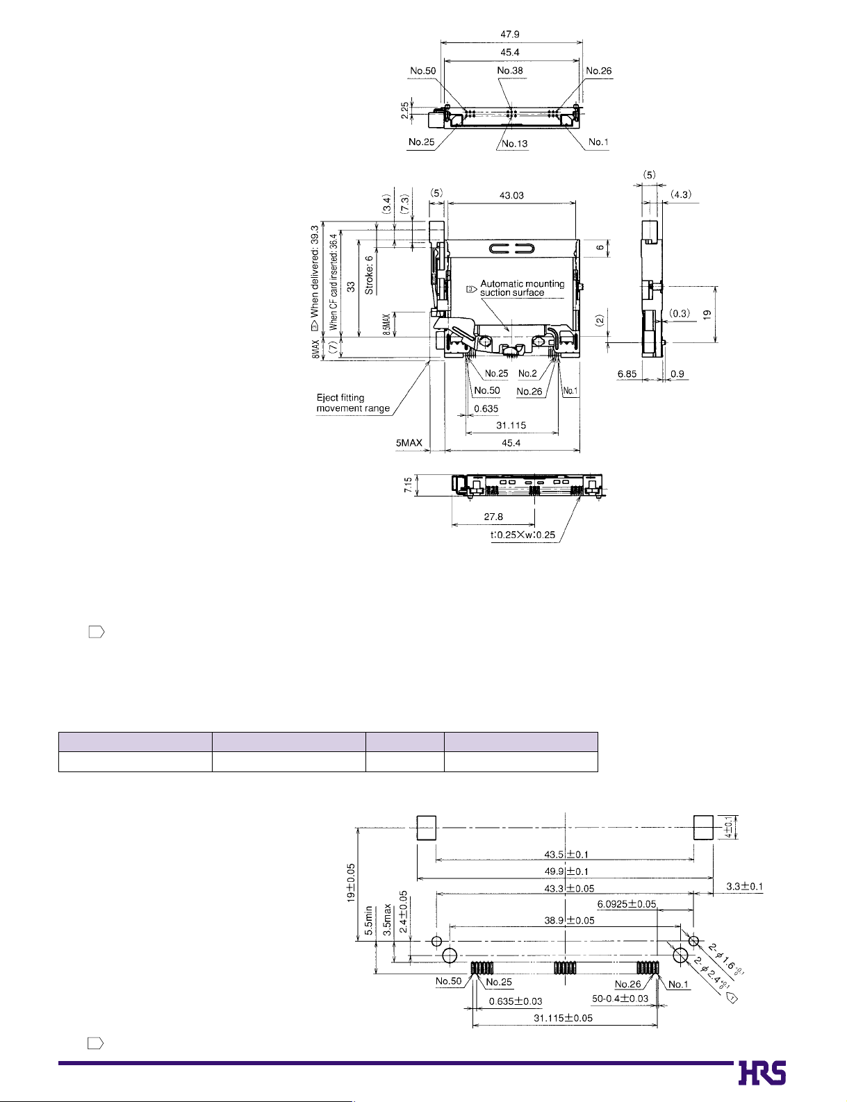
C9
●Eject button : Right side
●Offset : 0 mm
●Mounting style : Standard mounting
■Headers for Type I or II Cards
BPCB mounting pattern
Note 1:
This item is a (standard type) header for use with CompactFlash cards.
Note 2:
The dimensions of mating portion of this product comply with CFA standards.
Note 3:
This product can be automatically mounted. The suction surface for automatic mounting is positioned as illustrated in the figure.
This part is fixed in the initial condition, but released with a single operation of the ejector.
(Amount of actual card ejection: 3.5 mm)
Note 4:
The coplanarity (degree of flatness) of the SMT lead tip portion and the reinforced fitting mounting end face is to be 0.1 maximum.
Note 5:
Dimensions in parentheses ( ) are to be regarded as reference dimensions.
3
CL No.
640-7107-0MI21-50PD-SF-EJR 50 Tray
Part Number
Number of Contacts
Packaging
Note The holes
(2-Ø2.4 )
illustrated in the figure are only required when screws are used for fastening.
1
+0.1
0
Page 9
C10
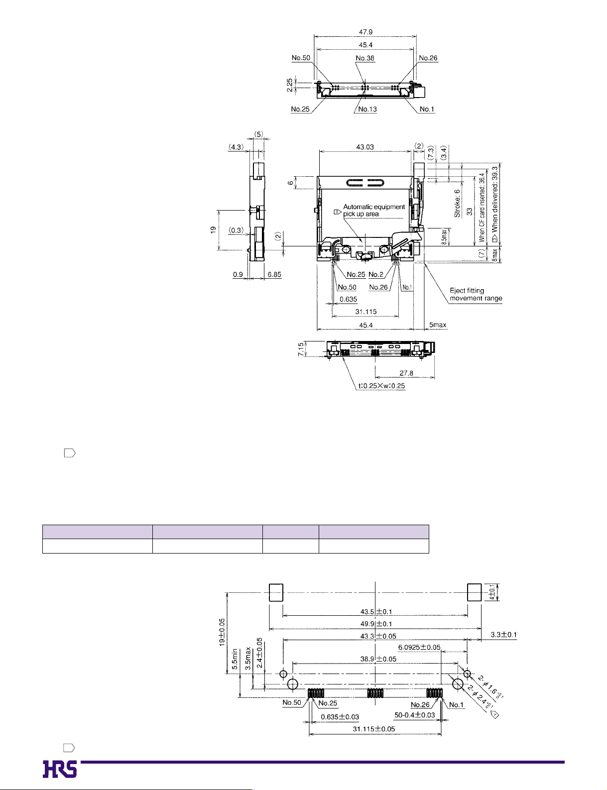
●Eject button : Left side
●Offset : None
●Mounting style : Standard mounting
■Headers for Type I or II Cards
BPCB mounting pattern
Note 1:
This item is a (standard type) header for use with CompactFlash cards.
Note 2:
The dimensions of mating portion of this product comply with CFA standards.
Note 3:
This product can be automatically mounted. The suction surface for automatic mounting is positioned as illustrated in the figure.
This part is fixed in the initial condition, but released with a single operation of the ejector.
(Amount of actual card ejection: 3.5 mm)
Note 4:
The coplanarity (degree of flatness) of the SMT lead tip portion and the reinforced fitting mounting end face is to be 0.1 maximum.
Note 5:
Dimensions in parentheses ( ) are to be regarded as reference dimensions.
3
CL No.
640-7108-3MI21-50PD-SF-EJL 50 Tray
Part Number
Number of Contacts
Packaging
Note The holes
(2-Ø2.4 )
illustrated in the figure are only required when screws are used for fastening.
1
+0.1
0
Page 10
C11
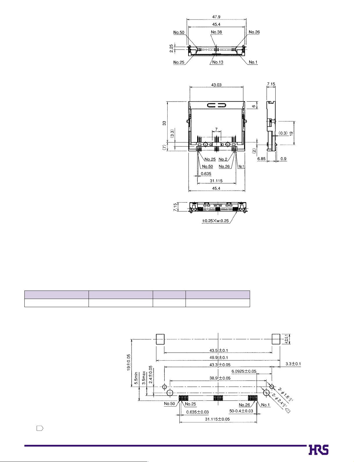
●Eject button : None
●Offset : None
●Mounting style : Standard mounting
■Headers for Type I or II Cards
BPCB mounting pattern
Note 1:
This item is a (standard type) header for use with CompactFlash cards.
Note 2:
The dimensions of mating portion of this product comply with CFA standards.
Note 3:
The coplanarity (degree of flatness) of the SMT lead tip portion and the reinforced
fitting mounting end face is to be 0.1 maximum
Note 4:
Dimensions in parentheses ( ) are to be regarded as reference dimensions.
CL No.
640-7109-6MI21-50PD-SF 50 Tray
Part Number
Number of Contacts
Packaging
Note The holes
(2-Ø2.4 )
illustrated in the figure are only required when screws are used for fastening.
1
+0.1
0
Page 11
C12
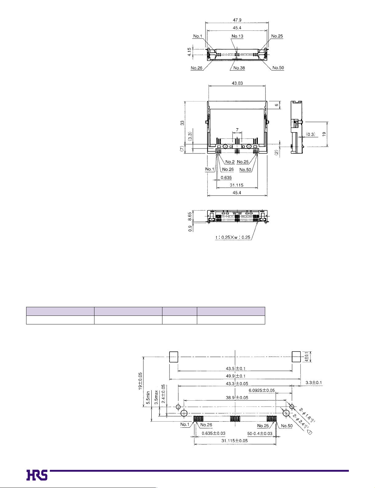
●Eject button : None
●Offset : None
●Mounting style : Reverse mounting
■Headers for Type I or II Cards
BPCB mounting pattern
Note 1: Coplanarity of all surface mount terminals and components is 0.1.
Note 2: Dimensions in parentheses ( ) are reference dimensions.
CL No.
640-7106-8MI21A-50PDR-SF 50 Tray
Part Number
Number of Contacts
Packaging
Page 12
C13
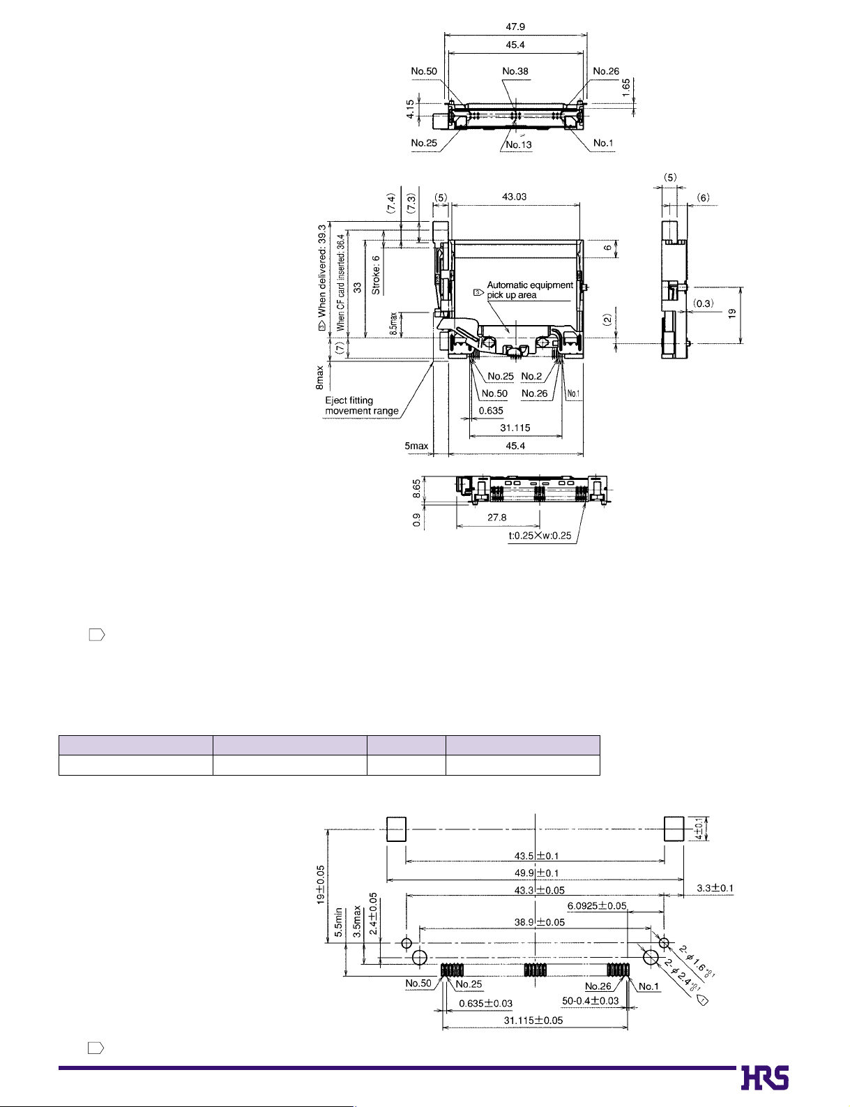
●Eject button : Right side
●Offset : 2.2 mm
●Mounting style : Standard mounting
■Headers for Type I and II Cards
BPCB mounting pattern
Note 1:
This item is a (standard type) header for use with CompactFlash cards.
Note 2:
The dimensions of mating portion of this product comply with CFA standards.
Note 3:
This product can be automatically mounted. The suction surface for automatic mounting is positioned as illustrated in the figure.
This part is fixed in the initial condition, but released with a single operation of the ejector.
(Amount of actual card ejection: 3.5 mm)
Note 4:
The coplanarity (degree of flatness) of the SMT lead tip portion and the reinforced fitting mounting end face is to be 0.1 maximum.
Note 5:
Dimensions in parentheses ( ) are to be regarded as reference dimensions.
3
CL No.
640-7101-4MI21A-50PD-SF-EJR 50 Tray
Part Number
Number of Contacts
Packaging
Note The holes
(2-Ø2.4 )
illustrated in the figure are only required when screws are used for fastening.
1
+0.1
0
Page 13
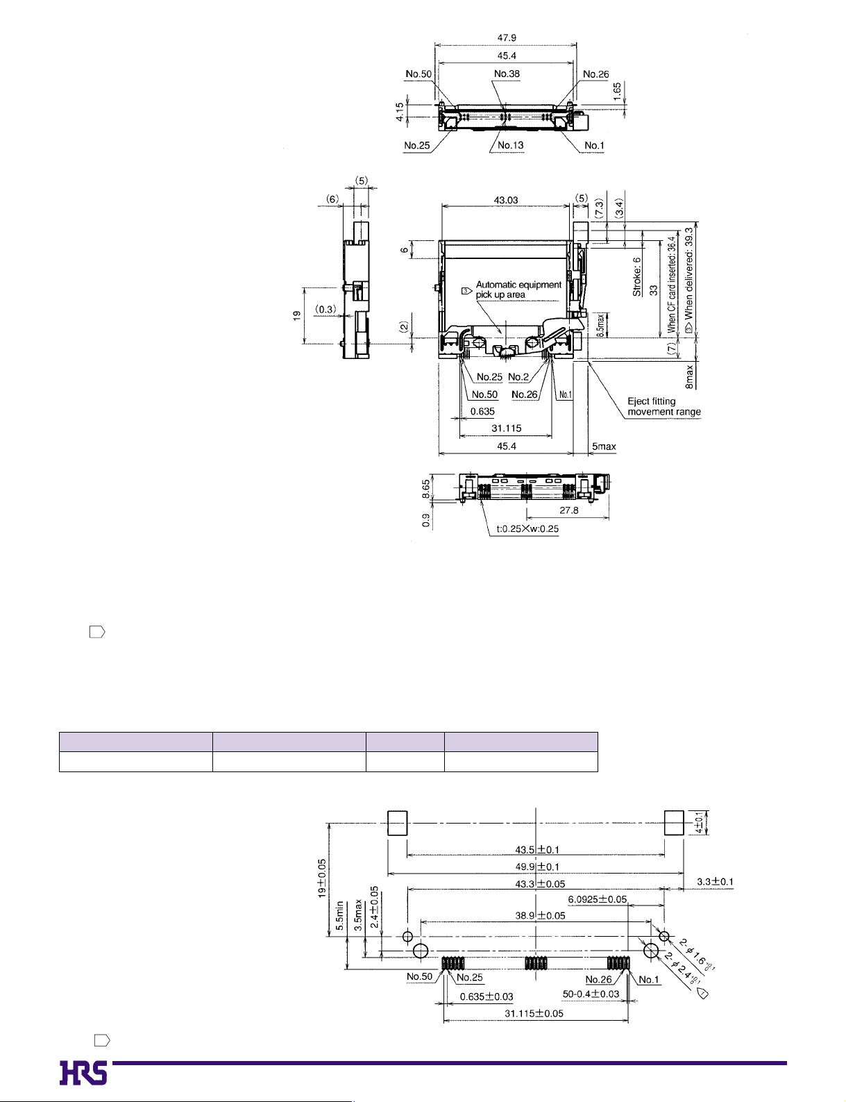
C14
●Eject button : Left button
●Offset : 2.2 mm
●Mounting style : Standard mounting
■Headers for Type I and II Cards
Note 1:
This item is a (standard type) header for use with CompactFlash cards.
Note 2:
The dimensions of mating portion of this product comply with CFA standards.
Note 3:
This product can be automatically mounted. The suction surface for automatic mounting is positioned as illustrated in the figure.
This part is fixed in the initial condition, but released with a single operation of the ejector.
(Amount of actual card ejection: 3.5 mm)
Note 4:
The coplanarity (degree of flatness) of the SMT lead tip portion and the reinforced fitting mounting end face is to be 0.1 maximum.
Note 5:
Dimensions in parentheses ( ) are to be regarded as reference dimensions.
3
CL No.
640-7102-7MI21A-50PD-SF-EJL 50 Tray
Part Number
Number of Contacts
Packaging
BPCB mounting pattern
Note The holes
(2-Ø2.4 )
illustrated in the figure are only required when screws are used for fastening.
1
+0.1
0
Page 14
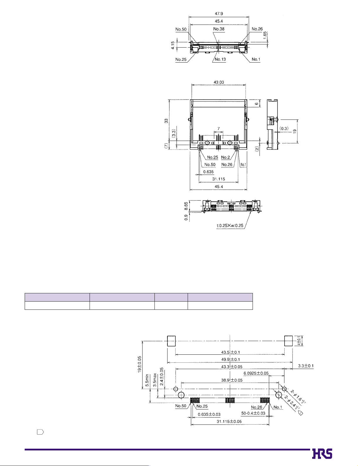
C15
●Eject button : None
●Offset : 2.2 mm
●Mounting style : Standard mounting
■Headers for Type I and II Cards
BPCB mounting pattern
Note 1: Coplanarity of all surface mount terminals and components is 0.1.
Note 2: Dimensions in parentheses ( ) are reference dimensions.
CL No.
640-7103-0MI21A-50PD-SF 50 Tray
Part Number
Number of Contacts
Packaging
Note The holes
(2-Ø2.4 )
illustrated in the figure are only required when screws are used for fastening.
1
+0.1
0
Page 15
C16
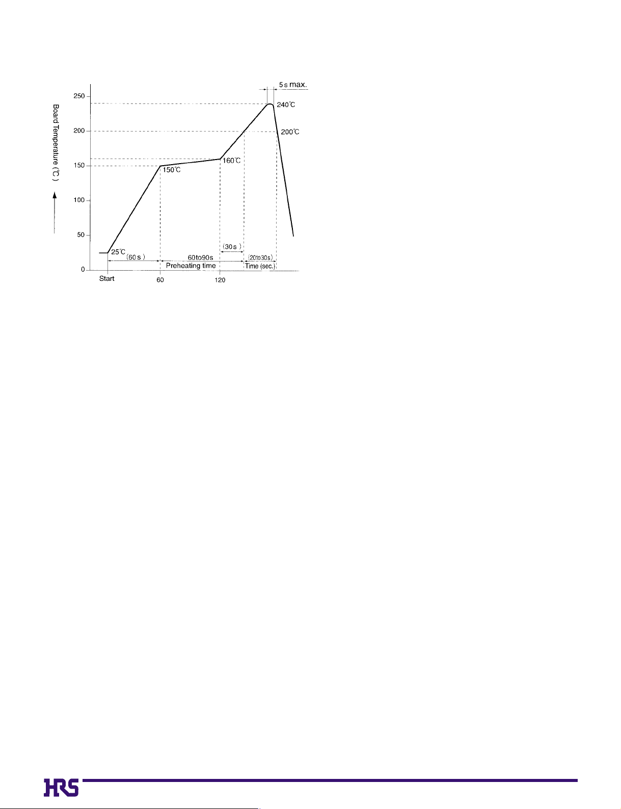
BTemperature Profile
Applicable Conditions
Reflow system
:
IR reflow
Solde
:
Paste type 63 Sn/37 Pb
(Flux content 9 wt%)
Test board Glass epoxy 60mm x 60mm x 1.6 mm
Metal mask thickness: 0.15 mm
Recommended temperature profile.
The temperature may be slightly changed according to the
solder paste type and amount.
Page 16
C17
BPrecautions for Use
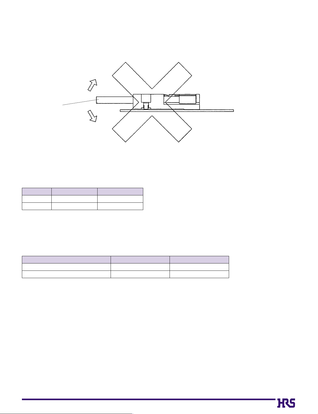
1. Differentiate the side of the card at the time of CF card insertion. This product is furnished with an wrong insertion
prevention mechanism which is compliant with CFA standards, but forced wrong insertion of the card may cause
damage to the card.
2. Do not move the CF card up and down when it has been partially inserted. It may cause damage to the connector
and card.
3. The package used for this product is the soft tray. We recommend a check before mounting, since the
adjustment may be reqaired depending on the type of mounter. For more detailed information, please
contact nearest Hirose account representative.
4. Recommended screw torque values.
2. Water Type Washing
When using water type cleaning agents (e.g., terpene, and alkali saponifiers), select the cleaning agent
based on the documentation issued by the various manufacturers of cleaning agents which describes the
effects on metals and resins.
Be careful that parts are not left with moisture remaining on them.
3. Washing Precautions
Residual flux or cleaning agent on the contacts when washing with organic solvents or water type
cleaners can give rise to the deterioration of electrical performance. In this regard it is important to check
whether a thorough washing has been performed.
1. Organic Solvent Washing
BWashing Conditions
This product is a no-wash item, but in the case of washing, please observe the following conditions.
Solvent
IPA (Isopropyl alcohol)
HCFC (Hydrochlorofluorocarbon)
Room temperature washing
YES
YES
Heated washing
YES
YES
Screw type
Steel screws
Brass screws
Standard
torque
0.142
0.124
Upper tolerance limit
0.180
0.168
[
Unit: N'm
]
Up
DownDown
CF Card
•
Screws : M2 X 0.4
 Loading...