

Page 1
MP568C USER MANUAL
© BART HRK
MP568C
User Manual
Page 2
MP568C USER MANUAL
© BART HRK
List of content:
1. The Microphone Preamplifier Section.
2. The Colour Section.
3. The Direct Input Section.
4. The Colour Signal Routing.
Page 3
MP568C USER MANUAL
© BART HRK
1. The Microphone Preamplifier Section.
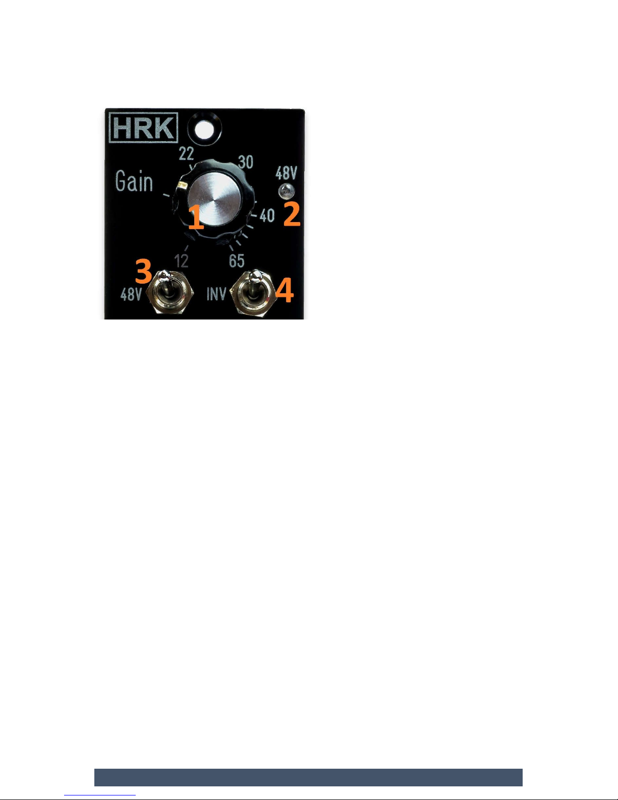
1 – Microphone / DI Gain - this control sets the total gain of the
MP568C. Values shown on the scale are approximately equal to the
total gain of the MP568C from input to output. The gain range is
from +12dB to +65dB. The signal sent to the colour section is
always 6dB lower than the total gain set by the Gain control knob.
2 – Phantom Power LED indicates the presence of the +48V on the
rear panel microphone input. The LED is connected to the +48V rack
power supply rail. If the LED is not working it may indicate the failure
of the main power supply.
3 – Phantom Power switch – turns ON and OFF the Phantom
+48V supply voltage. UP switch position shown on the picture
enables the Phantom supply.
4 – Phase Inverse switch – inverses the phase of the output signal
from the MP568C. UP switch position shown on the picture
inverses the output signal phase.
Page 4
MP568C USER MANUAL
© BART HRK
2. The Colour Section.
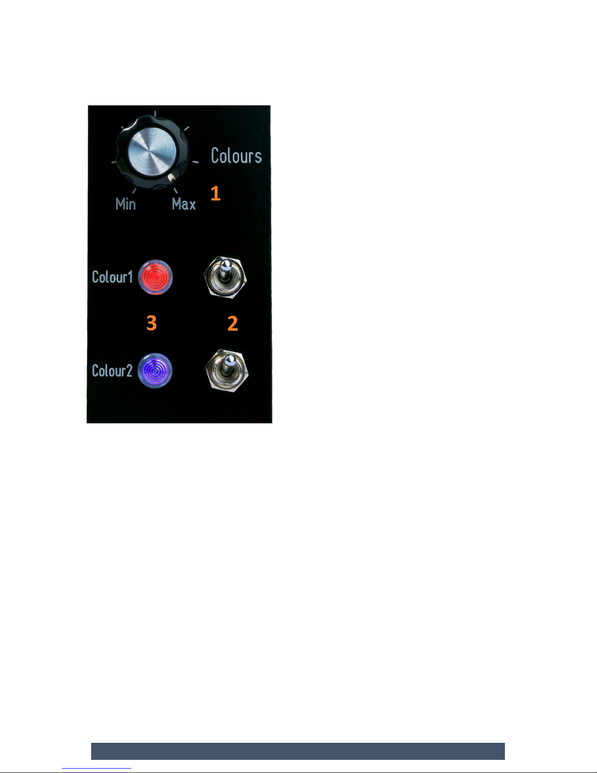
1 – Colours - Output Level Control – sets the total output level from
the colour section or directly from the mic preamp (if Colours are
disengaged) to the output. For the 12 o’clock knob position the total
output signal level from the MP568C is attenuated by 15dB. This is
NOT the Colour/Clean Balance Control.
2 – Colour1 and Colour2 switches enable the Colour Slot 1 and 2.
Up switch positions shown on the picture enables Colour Slot.
3 – Colour 1 and Colur2 HUE LEDs - indicate which Colour Module is
active. The colour of the light emitted by the LED will be unique
for different Colour Module type.
Page 5
MP568C USER MANUAL
© BART HRK
3. The Direct Input Section.
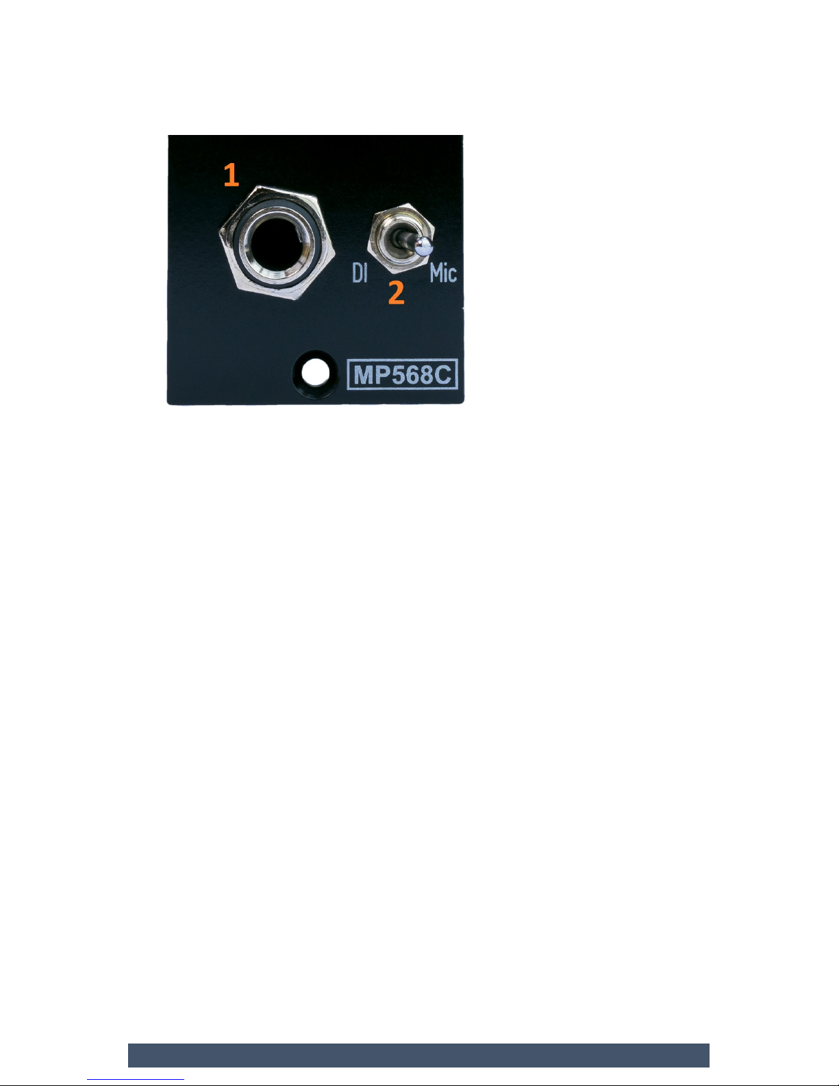
1 – Direct / Instrument Input* – High impedance discrete
unbalanced Instrument / Direct Input. The gain of the DI is
controlled by the main Gain knob in the Microphone Preamplifier
section. The gain range is from +12dB to +65dB.
2 – The Mic/DI Input selector switch – selects the input signal
source between the rear Microphone Input and the front panel
Instrument / Direct Input.
Note:
* The Direct Input uses special ultra-high impedance active circuitry.
Remember to be very careful when inserting the instrument cable
jack in to the DI, reduce the output level to minimum first.
Page 6
MP568C USER MANUAL
© BART HRK
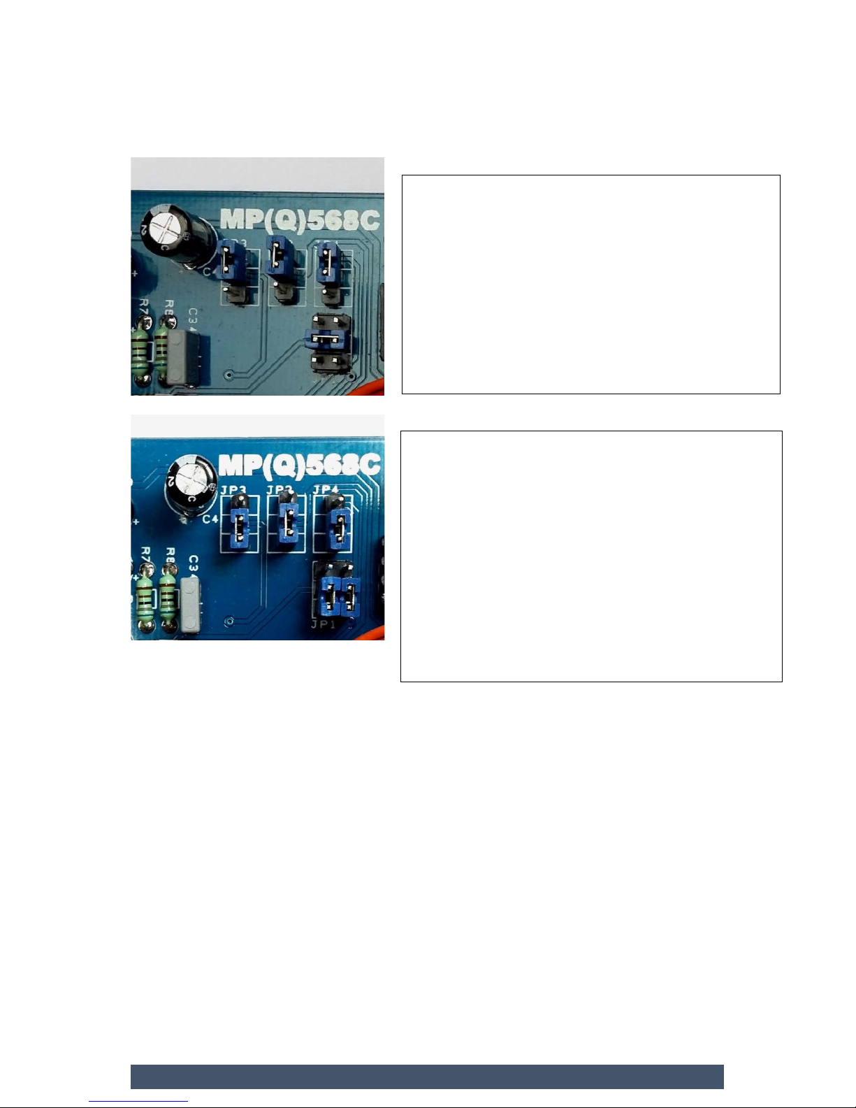
4. The EQ / Colour Signal Routing.
The default position. Signal is sent from the
Mic/DI input to the both Colour Modules. The
Colours level control is placed after 2 colour
modules. The Colours control knob sends the
signal to the output.
Both Colour Modules are effected by the Colours
knob.
MP568C is shipped in the default routing
configuration.
The post Colours knob position. Signal is sent
from the Mic/DI input to the first Colour
Module. The Colours level control is placed
after the first Colour Module. The Colours
control knob sends the signal from the first
Colour to the second Colour. Only the first
Colour Module is effected by the Colours knob.
Signal from the second colour is passed to the
output.
 Loading...