

Page 1

User’s Manual
EMX-AMP
HDMI Audio Extractor with 50 Watt Audio
Amplifier, Line Audio Input, RS-232 Ports
EMX-I-AMP
HDMI Audio Extractor with 50 Watt Audio
Amplifier, Line Audio Input, RS-232 Ports
and IP Control (Telnet & Internal Web GUI)
UMA1244 Rev NC
© Copyright 2016. Hall Research, Inc. All rights reserved.
1163 Warner Ave Tustin, CA 92780, Ph: (714)641-6607, Fax (714)641-6698
Page 2

HDMI Audio Extractor with Power Amplifier
2
Page 3

EMX-AMP
3
Table of Contents
1.0 INTRODUCTION ............................................................................................... 4
2.0 FEATURES ...................................................................................................... 5
2.1 PACKAGE CONTENTS........................................................................................ 5
3.0 SETUP ............................................................................................................. 6
3.1 INSTALLATION ................................................................................................. 6
4.0 OPERATION .................................................................................................... 7
4.1 FRONT PANEL ................................................................................................. 7
4.2 REAR PANEL ................................................................................................... 9
4.3 FACTORY DEFAULT ........................................................................................ 11
4.4 POWER CONNECTION ..................................................................................... 11
4.5 LINE IN CONNECTION .................................................................................... 12
4.6 L/R SPEAKER CONNECTIONS ........................................................................... 12
5.0 WEBGUI AND TELNET OPERATION ............................................................... 13
5.1 AMP POWER ................................................................................................. 13
5.2 AUDIO MIX ................................................................................................... 13
5.3 VOLUME CONTROL ......................................................................................... 13
5.4 EXTERNAL DEVICE CONTROL ........................................................................... 13
5.5 LOCATING THE DEVICE ON A LAN ...................................................................... 14
5.6 TELNET ........................................................................................................ 14
6.0 SENSE FUNCTION ......................................................................................... 14
6.1 PAGE SENSOR........................................................................................... 14
6.2 PAGE SENSOR INSTALLATION ........................................................................... 15
6.3 PAGE MUTE ON CONTACT CLOSURE .................................................................. 15
7.0 DUCKING FUNCTION ..................................................................................... 15
8.0 MONO OUTPUT MIX ....................................................................................... 15
9.0 SERIAL COMMANDS ..................................................................................... 16
9.1 SERIAL CONNECTIONS .................................................................................... 16
9.2 AUTOMATIC POWER CONTROL OF DISPLAY BASED ON HDMI INPUT DETECTION ......... 20
9.3 DEVICE ADDRESSING FOR SPECIAL DAISY-CHAIN OPERATION .................................. 20
10.0 TROUBLESHOOTING ................................................................................... 21
11.0 SPECIFICATIONS ......................................................................................... 22
TRADEMARKS USED IN THIS MANUAL
Hall Research and its logo are trademarks of Hall Research. Any other trademarks mentioned
in this manual are acknowledged as the property of the trademark owners.
FCC RADIO FREQUENCY INTERFERENCE STATEMENT
This device complies with part 15 of the FCC Rules. Operation is subject to the following two
conditions:
1. This device may not cause harmful interference, and
2. This device must accept any interference received, including interference that may cause
undesired operation
Page 4
HDMI Audio Extractor with Power Amplifier
4
1.0 Introduction
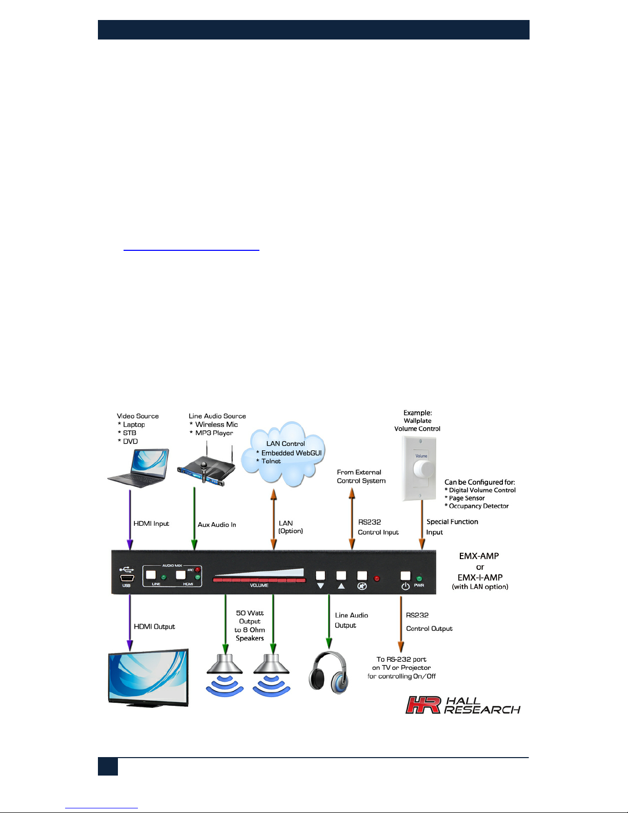
The EMX-AMP is a 4K HDMI Audio Extractor with built-in 50 watt audio amplifier for
direct connection of 8 ohm speakers. It provides an additional line-level stereo audio
input that can be mixed with the HDMI audio. Volume can be controlled using front panel
buttons, RS-232 commands, or via an external rotary digital encoder.
The EMX-AMP provides an independent RS-232 output port that can be used to control
other devices. Typically it is used to control the power on/off state of the TV or video
projector connected to its output.
Full EDID management is provided with the ability to learn, download, upload, emulate or
pass-thru the EDID from the connected display. A USB port is featured on the front panel
that can be used to configure the device operation via a free Windows™ GUI available
from
http://www.hallresearch.com.
The EMX-AMP can pass commands from its RS-232 input to the RS-232 output. It also
has the ability to store user defined ON and OFF commands for controlling devices
connected to its RS-232 output (e.g. to control power on/off function of display).
The stored RS-232 commands can be triggered automatically (based on detecting HDMI
input) or manually by user command (RS-232, Telnet, WebGUI), or contact closure.
An IP enabled version is available (EMX-I-AMP) adds a Telnet and WebGUI. This gives
the user the ability to control the device through a PC or Smartphone. Telnet control uses
the same commands as the serial interface.
Figure 1 – Connection Diagram
Page 5

EMX-AMP
5
2.0 Features
• 4K HDMI audio extractor with EDID management
• Built-in 50 watt amplifier for connection to 8 Ohm speakers (25 watts/channel)
• Audio input for connecting line-level audio inputs (e.g. wireless microphones).
• Control via, front panel, RS-232, digital pot (rotary encoder), Webpage or Telnet
• HDMI Ducking (when Line input is detected, HDMI sound volume in the mix is
automatically lowered)
• Primary RS-232 port for device control
• Secondary RS-232 port for auxiliary device control
• Store separate ON/OFF RS-232 commands for the auxiliary devices
• Supports HDMI, DVI, HDCP, 3D and Deep color
• Stereo or Mono output
• Priority Paging Sensor input (for automatically muting of the audio output)
• Compact, Rugged, Reliable, and Economical
• Made in the USA
2.1 Package Contents
Qty (1) EMX-AMP
Qty (1) 18V DC Universal DC Power Adapter
Qty (1) User’s Manual
Qty (1) Type A to Mini-B USB cable
Qty (1) 4 Position Screw Terminal Strip
Qty (1) 9 Position Screw Terminal Strip
Page 6

HDMI Audio Extractor with Power Amplifier
6
3.0 Setup
3.1 Installation
• Connect an HDMI compatible source signal to the HDMI IN connector.
• Connect the HDMI display device to the HDMI OUT connector. Note that even if
the HDMI output is disconnected, the EMX-AMP extracts video from the HDMI
source.
• Connect a pair of 8 ohm loudspeakers to the speaker output screw terminals.
For connecting more than 2 speakers, please see Section
4.6.
• Optionally, connect a compatible line-level audio source to the LINE IN
connector. (e.g., wireless microphone or MP3 player). See sections
4.2 and 4.5
for more information on the Line In connector.
• Optionally, connect a compatible line-level audio output device to the LINE
OUT connector. (e.g., headphones, assistive listening devices). The Line out
signal volume is variable and is set by adjusting output volume
• Optionally, connect a compatible RS-232 control device to the RS-232 IN 3-pin
terminal connector. (e.g., Serial Controller)
• Optionally, connect the compatible RS-232 device to be controlled to the RS-
232 OUT 3-pin terminal connector. (e.g., Projector or LCD)
• Optionally, if the device is EMX-I-AMP, connect it to your LAN using a CAT5e/6
cable plugged to the LAN connector.
• Optionally, connect one of the following functions to the 3 configurable pins on
the screw terminal. The function of these pins can be set by the user via the free
Windows GUI available on product's website. By default the pins are configured
to connection of external rotary volume knob. The following operation modes
are available
o External digital rotary encoder (for volume control using a knob) -Default
o Priority Page Sensor (for detecting page announcement)
o Occupancy Detector (to trigger the unit to send out Power On/Off
commands to the display).
See section
4.2 for details.
Page 7
EMX-AMP
7
4.0 Operation
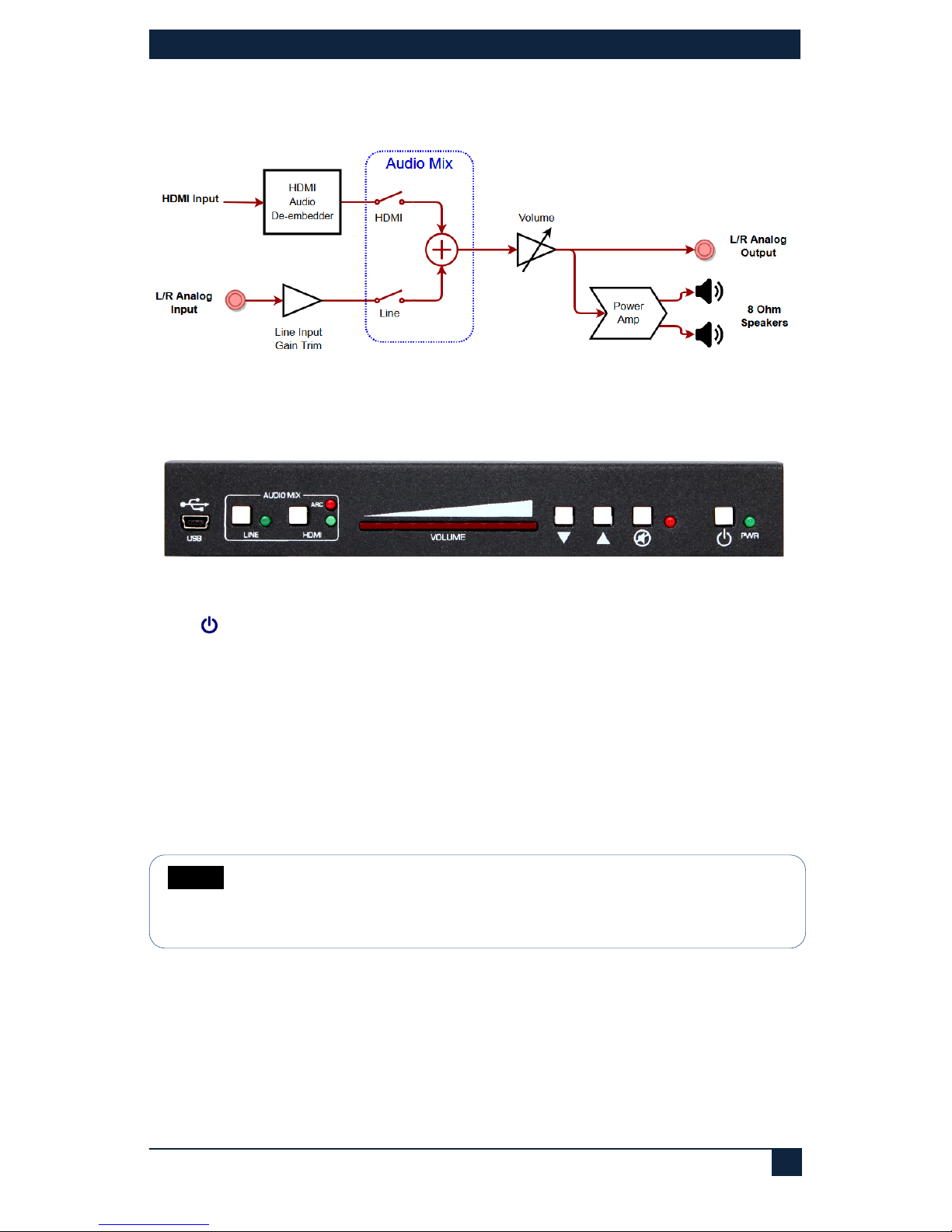
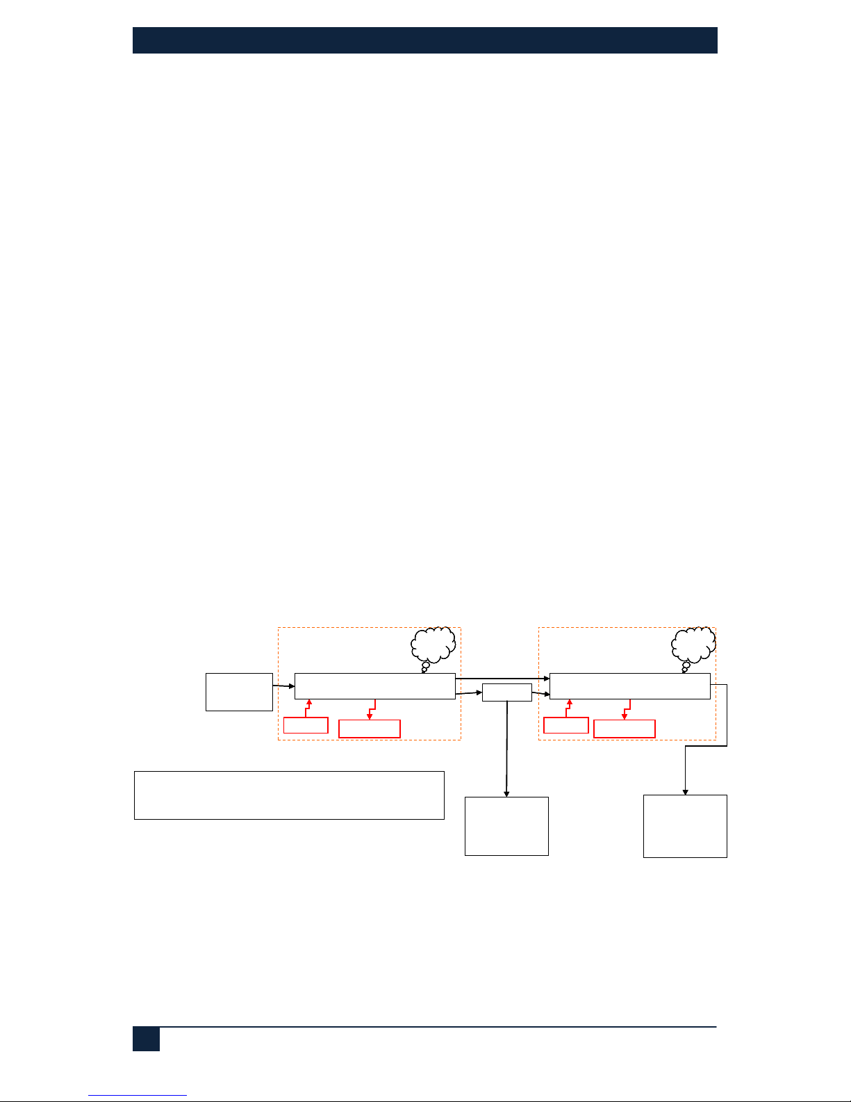
The following is a functional block diagram of the audio routing in the EMX-AMP:
Figure 2 – Audio Routing and Processing Diagram
4.1 Front Panel
Figure 3 - Front Panel
PWR
Press this button to turn the unit on and off. When the unit is ON, the LED glows.
MUTE
Press this button to mute the output audio. When the unit is muted, the LED glows.
▲& ▼
Press these buttons to increase or decrease the output volume. Volume can be adjusted
regardless of mute status. If volume is changed when the output is muted, it will be at the
new level when un-muted.
LED Volume Bar
The illuminated LEDs show the current audio setting 0 to100%. The level is adjusted
using the ▲& ▼ buttons.
NOTE
Volume setting affects both the Speaker output as well as the 3.5mm
stereo output. The volume of the audio embedded in the HDMI output is
not affected.
Page 8
HDMI Audio Extractor with Power Amplifier
8
Audio Mix Buttons
The LINE and HDMI buttons are used to select audio inputs. When both are selected, the
audio from each source are added together.
LINE
Press this button to select the Line input and add it to the output audio. When
the Line input is selected, the LED glows.
HDMI
Press this button to select the audio embedded in the HDMI input and add it to
the output audio. When the HDMI input is selected, the LED glows.
Using the HDMI ARC audio
Instead of using the audio from the HDMI input, the user can use the audio signal
returning from the TV connected to the output (TV must support ARC function). To
reassign the HDMI audio from INPUT to ARC, use the free Windows GUI available for
free download on the product's website.
When configured to use the ARC function, selecting the HDMI button on the front panel
lights both HDMI and ARC LEDs at the same time. This indicates the ARC pin in the
HDMI is being selected.
USB
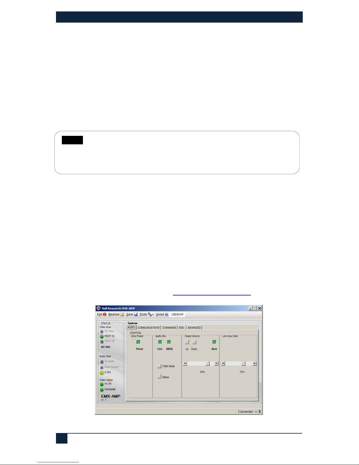
Connect the supplied USB cable to a compatible Windows™ PC using for use with the
Software GUI available for download from
http://www.hallresearch.com.
Figure 4 – Free Windows® GUI
NOTE
If nothing is connected to the 3.5mm audio input, it is recommended to
unselect the LINE in the audio mix. This eliminates any possible residual
noise picked up by the analog circuits connected to the unused LINE
input
Page 9
EMX-AMP
9
4.2 Rear Panel
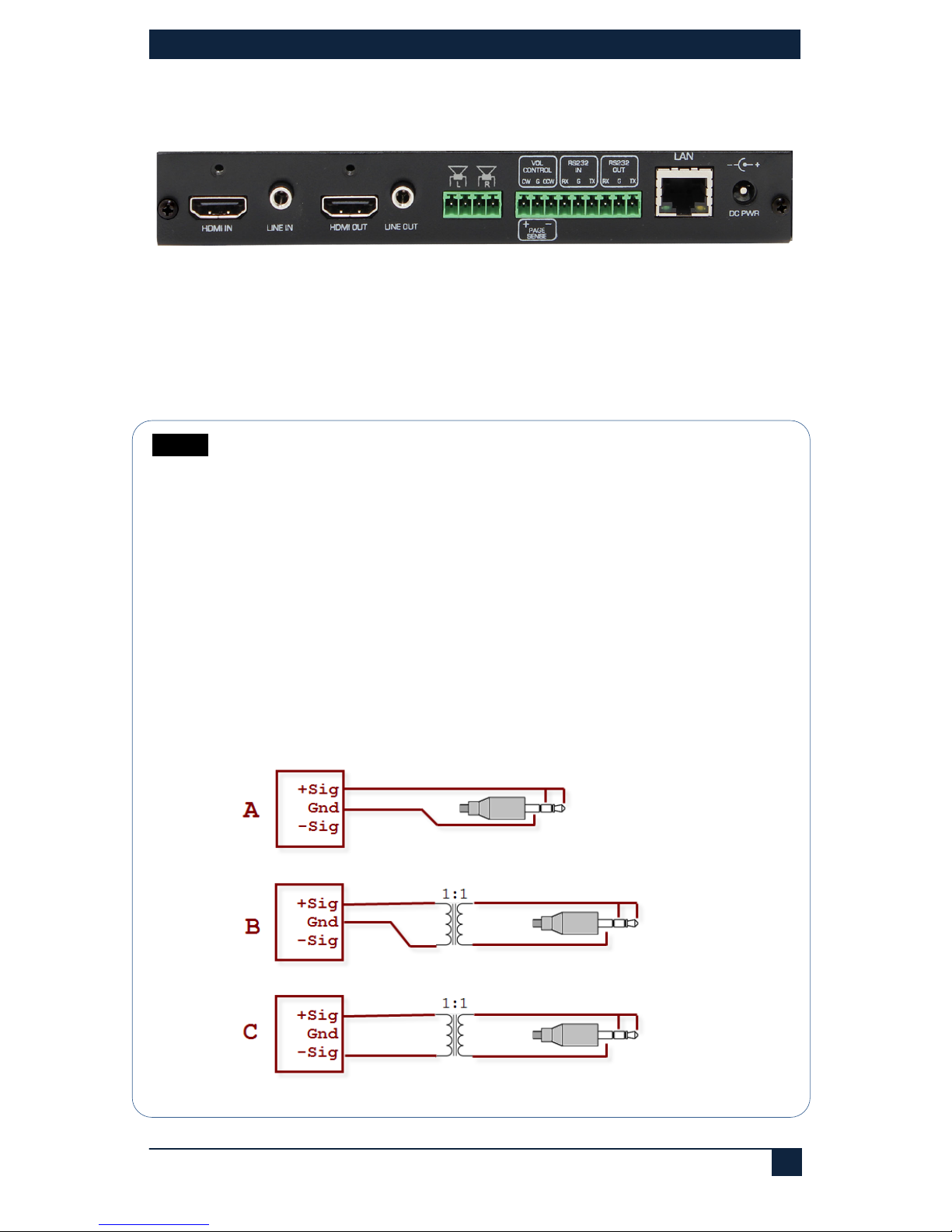
Figure 5 – Rear Panel
HDMI IN
Connect to compatible video source. (e.g., such as a DVD or Blu-ray player).
LINE IN
Connect to compatible line level audio source. (e.g., such as a MP3 or Microphone).
NOTE The Line input is configured for nominal Consumer Level (typical of
MP3 players or wireless microphone receivers).
This input connector is stereo (Tip=Left channel, Ring=Right
Channel). Care must be taken when connecting to a mono signal or
a balanced signal.
When connected to an unbalanced mono source, both tip and ring of
the EMX-AMP should be connected to the mono audio. Adapter
cables are commercially available.
If connecting to a balanced mono source where there are +Sig and Sig in addition to ground, make sure it has enough level (not
compatible with low-level microphones, and connect using one of the
following methods.
Figure 6
Page 10
HDMI Audio Extractor with Power Amplifier
10
HDMI OUT
Connect to compatible video sink. (e.g., such as a LCD or Projector).
LINE OUT
Unbalanced stereo output. Connect to compatible line level audio output devices (e.g.,
such as headphones)
L/R Speaker Outputs
Connect 8 or 16 ohm speakers to the 4-position terminal strip, 25 watts per channel
maximum. See section
4.6 for more information.
VOL Control / PAGE Sense
These connections have different purposes based on the system configuration.
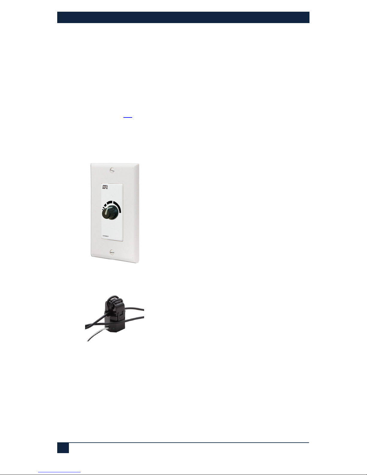
• By default, connect a compatible rotary encoder to the CW, CCW and GND
terminals for system volume control.
Figure 7 - Optional UI-KNOB-DP
• OR, connect a compatible PAGE SENSOR (Model VSA-PGSNS) to the CW
and CCW terminals for automated PAGE Muting control.
Figure 8 - Optional VSA-PGSNS page sensor clamp
• OR, connect a switch between the CW and GND terminals for automated
PAGE Muting control. If paging system has a relay output that indicates page
in progress, instead of using the page sensor clamp described above, you can
connected the relay to these terminals and configure the system to use it.
• OR, connect a switch between the CCW and GND terminals for automated
transmission of the user programmed RS-232 ON and OFF strings from the
RS-232 OUT terminals. This is typically used to send RS-232 commands
based on contact closure input from compatible occupancy sensor.
Page 11
EMX-AMP
11
RS-232 IN
Connect the PC’s RS-232 port to the input of the unit with a 3-pin terminal connector.
RS-232 OUT
Connect RS-232 out to the controlled device such as a projector using a 3-pin terminal
cable.
LAN
Available on the Model EMX-I-AMP, connect to the compatible LAN network.
DC PWR
Connect to the power supply shipped with the unit. See Section
4.4
4.3 Factory Default
If the Power Button and Line Button are held for more than 3 seconds, this model can be
set to the ‘FACTORY DEFAULT’ state.
4.4 Power Connection
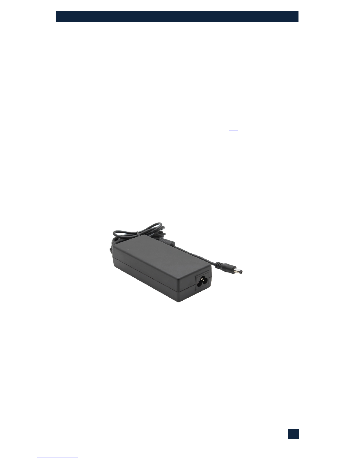
A 120/240 VAC 50/60 HZ to 18 Volt DC 5A external universal power supply provides all
the power required for the system to operate (P/S Model: 511-PSD1850APL06).
Figure 9 – Power Supply
Page 12
HDMI Audio Extractor with Power Amplifier
12
4.5 LINE IN Connection
The LINE IN connection expects a consumer line level signal and is optimized for stereo
line output of PC's, MP3 players, Smart Phones, etc.
Since various sources may possibly output less or more than nominal levels expected,
there is a gain/trim adjustment on the line input to help set the level of Line Input about
the same as the audio in HDMI.
The Line input is not compatible with low level microphones. It does not provide enough
gain for low level microphone signals.
When using wireless (RF or IR based) microphones use the line output of the
Microphone receiver to connect to the input of the EMX-AMP.
4.6 L/R Speaker Connections
The audio amplifier is designed to drive loads equal to or greater than 8 Ω
Using lower loads may cause an over-current shutdown of the audio amplifier, this be
detected and the amplifier will be reset.
Audio output from the amplifier will mute during this time.
It is recommended that when using a single speaker for each side to use 8 or 16 Ω
speakers.
The amp can drive 50 watts total (25 watts per channel) when using 8 Ω speakers,
which may be loud for a small room. Using 16 Ω speakers will cut the power delivered
by half.
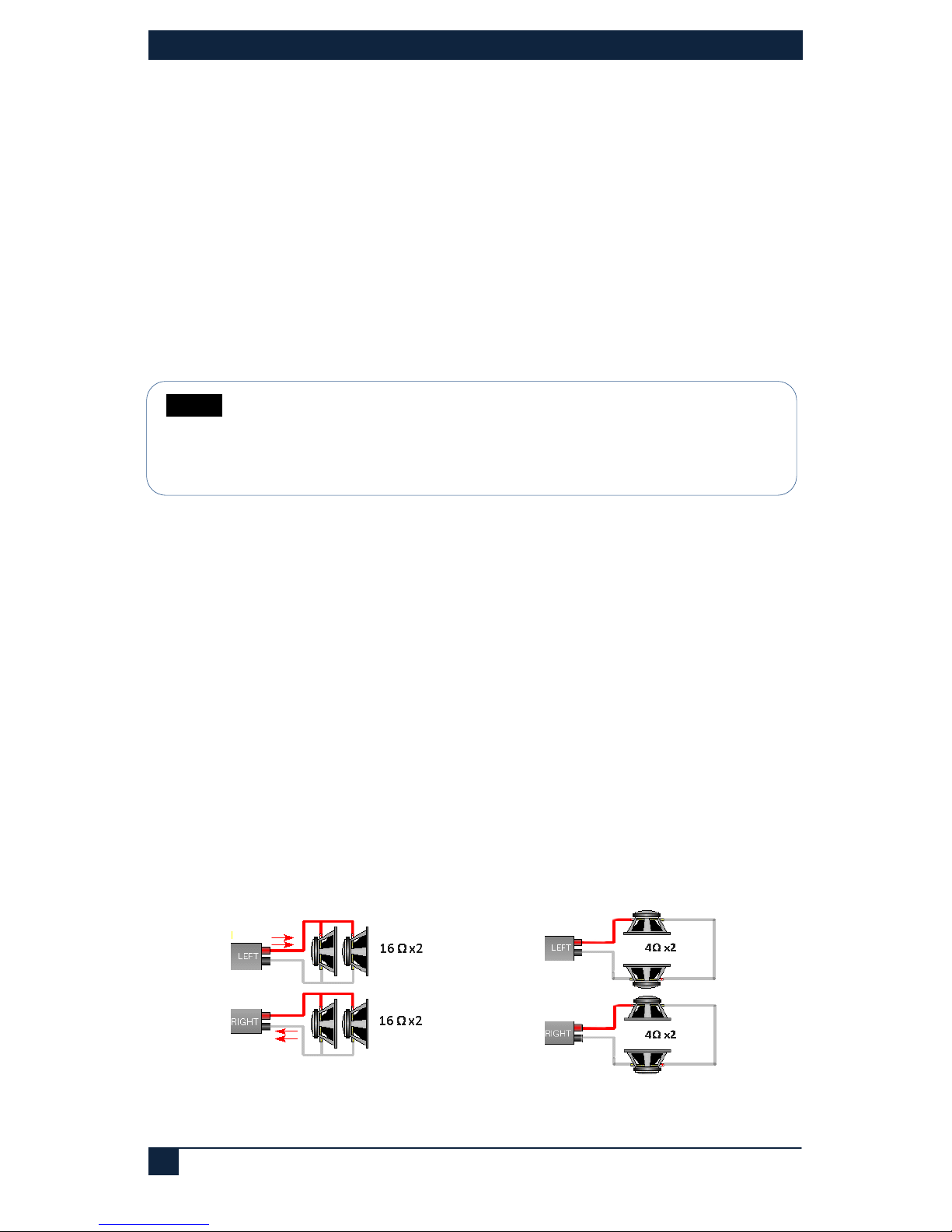
To drive 2 speakers from each side(total of 4 speakers in the room), connect two 16 Ω
speakers in parallel or two 4Ω or 8 Ω speakers in series as shown below. Never
connect two 8 Ω speakers in parallel.
Figure 10 – Speaker Connection Example
NOTE
If nothing is connected to the 3.5mm audio input, it is recommended to
unselect the LINE in the audio mix. This eliminates any possible residual
noise picked up by the analog circuits connected to the unused LINE
input
Page 13
EMX-AMP
13
5.0 WebGUI and Telnet Operation
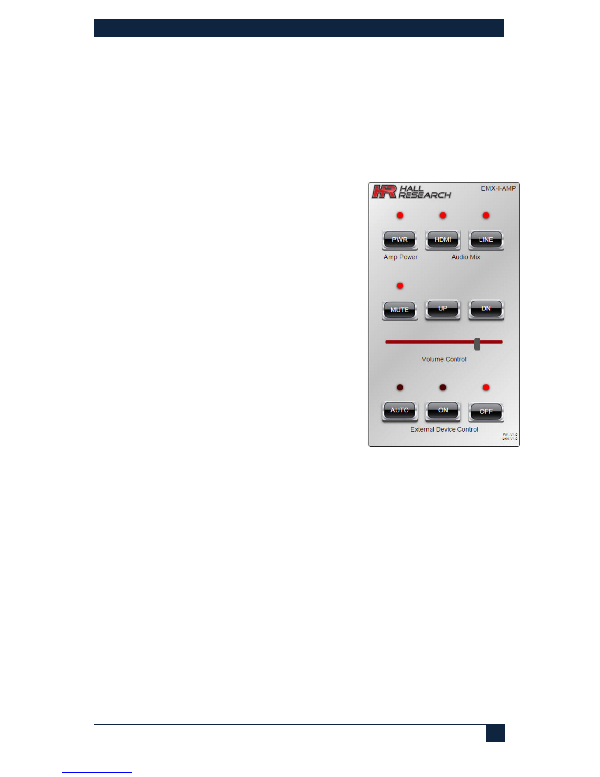
EMX-I-AMP has a built in webpage that can control the basic functions of this model via
LAN. You can power the device on and off, select the Audio Mix, control volume
up/down/mute functions, and if you have programmed RS-232 ON and OFF commands
of your display, you can also control the power of the TV (or set it for Auto where the
commands are automatically sent based on video detection).
The webpage has buttons and indicators that show the state of that feature. The
indicators are active even if buttons are disabled.
5.1 Amp Power
PWR Button
Click this button to turn the unit ON. Note: When the
system is OFF, all buttons are disabled (grayed out)
except for the PWR button.
5.2 Audio Mix
HDMI Button
Click this button to enable the HDMI Audio in output
LINE Button
Click this button to enable the LINE IN Audio. If you
are not using Line Input in your setup, disable it.
5.3 Volume Control
UP & DN Buttons
Click these buttons to Increase or decrease the
volume. Slide the volume bar to adjust the volume.
Mute Button
Click this button to mute the output audio
5.4 External Device Control
These buttons are for controlling the device connected to the RS-232 output port of the
EMX-I-AMP (typically a TV or video projector with RS-232 control port).
AUTO Button
Click this button to enable or disable the Auto Output Command feature. In this mode the
unit will look for HDMI signal on its input and will sent programmed commands to the TV.
Note: When AUTO is enabled, the PWR, ON and OFF buttons are disabled.
ON Button
Click this button to send the user programmed RS-232 ON String to RS-232 OUT
OFF Button
Click this button to send the user programmed RS-232 OFF String from the RS-232 OUT
Figure 11– Webpage Example
(As viewed on a smart phone)
Page 14
HDMI Audio Extractor with Power Amplifier
14
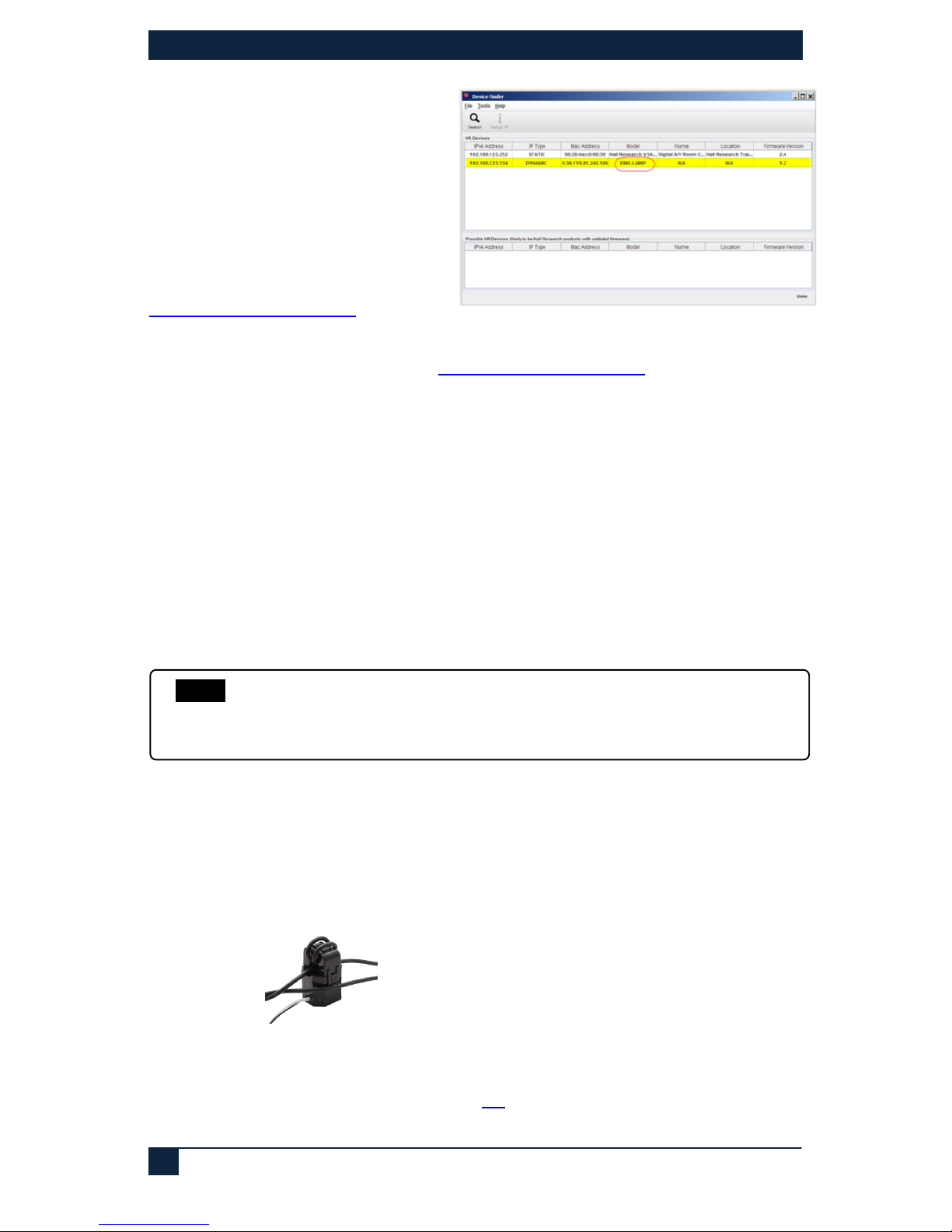
Figure 12– Windows GUI
5.5 Locating the device on a LAN
This model is shipped from the
factory set for DHCP. The device will
get an IP address from the
compatible LAN network router.
The users may set the device to have
a static address by using the
Windows™ Software GUI available
for download from
http://www.hallresearch.com.
The Hall Research Device Finder
software is available for download from
http://www.hallresearch.com to locate all models
on compatible LAN networks.
5.6 Telnet
The model EMX-I-AMP is controllable across a compatible LAN network via the device IP
address on PORT 6324. The control commands are the same as the RS-232 control
commands.
6.0 SENSE Function
This model has the ability to implement “priority page sense” function to mute the audio
output when the system senses a page in the PA system.
Two methods can be used. (1) PAGE SENSOR CLAMP or CONTACT CLOSURE.
6.1 PAGE SENSOR
This an optional non-invasive audio transformer clamp that goes over existing wiring of
the PA system. Simply clamp it over one of the wires going to the PA speakers. It detects
PA announcement by monitoring the electric current in the wire when an announcement
is in progress. When a “Page Sense” signal of sufficient amplitude is detected, the audio
output of the EMX-AMP is automatically muted.
Figure 13 – Optional Page Sensor Clamp
If it is not possible to use the clamp (for example if the paging speaker is using Cat5
cabling), then if the paging system has a relay output (for alarm), you can use the contact
closure to mute the audio output (see section
6.3)
NOTE
Since page sense feature uses the same screw terminals as the rotary
encoder, it is not available when the multifunction pins are configured for
Rotary Encoder.
Page 15

EMX-AMP
15
6.2 Page Sensor Installation
• To install the VSA-PGSNS, locate the external PA wiring.
• Isolate one of the wires from the pair to run through the sensor. Carefully
separate the wire pair taking caution not to cut the line or expose the wire
inside the insulation.
• Wrap one of wires around the sensor lid 2-3 times as shown. The sensitivity is
related to the number of turns used.
• Connect the leads on the sensor to the EMX-AMP terminals labeled “SENSE”
(CW and CCW). Connect white to CW (+) and black to CCW (-) terminals.
• With the sensor installed the sensitivity can be adjusted using the Windows™
Software GUI.
6.3 Page Mute on Contact Closure
Connect a normally open switch between the CW and GND terminals.
Closed = Muted. Open = NOT Muted.
7.0 Ducking Function
The EMX-AMP provides a basic “Ducking” feature where if audio is detected on the Line
Input, the HDMI audio volume is automatically reduced. This is a useful feature when the
line input is from a speaker’s voice (e.g. via wireless microphone system). If Ducking
function is active, then when the speaker begins to talk, the EMX-AMP will reduce the
volume of the HDMI. This way the speaker’s voice will be heard.
The “Ducking” feature constantly monitors the LINE IN audio level and when a signal of
sufficient amplitude is detected, the HDMI audio input volume level will automatically be
‘reduced’ by the amount specified in the configuration. After the LINE IN audio level
drops below the threshold, and after small delay, the HDMI audio input will automatically
be returned to its previous level.
The “Ducking” Threshold and Ratio are settable via the Windows™ Software GUI.
8.0 Mono Output Mix
The EMX-AMP has the ability to mix the left and right channels and produce a mono
output (where both left and right speakers sound the same). This selection is done via
the Windows GUI or using the MOx serial command.
NOTE The optional Page Sensor works with 25 V or 70 V and even some 8
Ohm PA systems. It is not designed for, two-way intercoms or IP-based
paging systems. The sensor measures the AC audio current going to the
external PA speaker and compares it against a “set point” to ignore
background PA system noise. The mute trigger sensitivity is easily set
using the software from any PC.
Page 16

HDMI Audio Extractor with Power Amplifier
16
9.0 Serial Commands
• The following table lists the RS-232 commands:
o Each command must be terminated by a single carriage return character
(hex 0D).
o Invalid input, spaces and line feeds characters (hex 0A) are ignored.
• RS-232 communication on the RS-232 IN terminal strip is:
o 9600 bps, 8 Bit, No Parity, 1 Stop bit.
• RS-232 communication on the RS-232 OUT terminal strip is:
o Configurable, factory default is 9600 bps, 8 Bit, No Parity, 1 Stop bit.
o The OUTPUT baud rate can be changed via Software GUI or via the “XBx”
and “XPx” commands.
• <CR> in the table below refers to a single carriage return character (0x0D)
• “Error – Invalid Command” is sent in response to invalid RS-232 commands
• “Error” is sent in response to invalid command parameters
9.1 Serial Connections
• (3) Screw Terminal - RS-232 IN (TX, GND and RX)
• (3) Screw Terminal - RS-232 OUT (TX, GND and RX)
Command Response Function and Example
FW
FWx.y<CR>
Current firmware version.
X and Y represent the firmware version numbers.
(e.g., FW1.1<CR>)
PWx PWx<CR>
Controls power status.
PW?<CR> – Query current power setting
PW1<CR> -- Turn power on
PW0<CR> -- Turn power off (Factory Default)
LRx LRx
Controls Line Level Audio Input
LR?<CR> – Query current Line Level Audio setting
LR1<CR> -- Turn on Line Level Audio (Factory Default)
LR0<CR> -- Turn off Line Level Audio
HDx HDx<CR>
Controls HDMI Audio Input
HD?<CR> – Query current HDMI Audio setting
HD2<CR> -- Turn on ARC Audio (valid in ARC Mode – AR1)
HD1<CR> -- Turn on HDMI Audio (Factory Default)
HD0<CR> -- Turn off HDMI Audio
VOLxxx
VOLxxx<CR>
Controls Audio output level. Allowable range is 0 to 100%.
VOL?<CR> – Query current volume level
VOL50<CR> -- Set volume level to 50%
VOL0<CR> -- Set volume level to 0% (Factory Default)
VUPxxx
VOLxx<CR>
Controls Audio output level. Optional range is 0 to 100%.
VUP<CR> -- Adjust volume level up 2%
VUP10<CR> -- Adjust volume level up 10%
VDNxx
VOLxx<CR>
Controls Audio output level. Optional range is 0 to 100%.
VDN<CR> -- Adjust volume level down 2%
VDN10<CR> -- Adjust volume level down 10%
Page 17
EMX-AMP
17
Command Response Function and Example
VCx
VCx<CR>
Controls sub-circuit gain settings
VC?<CR> – Query current volume/gain control setting
VC0<CR> -- Line Input Preamp Gain (defaulted to 70%)
VC1<CR> -- Reserved (do not use)
VC2<CR> -- Reserved (do not use)
VC3<CR> -- Overall Output Gain Setting (Factory Default)
Note:
It is recommended that the user always return the setting to
VC3 (default) after use. VC0 command is used to adjust the
balance between HDMI and Line input levels. After the
adjustment the user must set the VC to 3 so volume commands
affect the output volume and not preamp gain. VC0 is
controllable through the USB port using Windows GUI. Please
see
Figure 2 for audio signal flow diagram.
For example:
To set the LINE Input to 50% Volume and then reset the control
to the default LINE+HDMI/ARC, use:
VC0<CR>VOL50<CR>VC3<CR>
MUTx
MUTx<CR>
Controls the MUTE status
MUT?<CR> – Query current Mute Setting
MUT1<CR> -- Turn on Audio Muting
MUT0<CR> -- Turn off Audio Muting (Factory Default)
ARx
ARx<CR>
Controls ARC Mode (Audio Return Channel)
AR?<CR> – Query current ARC mode setting
AR1<CR> -- Turn on ARC Mode
AR0<CR> -- Turn off ARC Mode (Factory Default)
• When ARC mode is turned off, using the HDMI button on
the front panel will toggle between HDMI audio and no
HDMI audio.
• When ARC mode is turned on, using the HDMI button on
the front panel will toggle between ARC Audio and No
ARC Audio.
AUx AUx<CR>
Controls AUTO DETECT Mode
AU?<CR> – Query current Auto Detect Mode Status
AU1<CR> -- Auto Detect Mode Active
AU0<CR> -- Auto Detect Mode In-Active (Factory Default)
EDx
EDx<CR>
Controls EDID mode setting
ED?<CR> – Query current Mute Setting
ED1<CR> -- Pass-Thru (Factory Default)
ED0<CR> -- Emulated
FD
FD<CR>
Resets device to Factory Defaults
Unit will reboot
MOx MOx<CR>
Controls the MONO/STEREO Status
MO?<CR> – Query current MONO/Stereo Setting
MO1<CR> -- Turn on MONO
MO0<CR> -- Turn off MONO (Stereo) (Factory Default)
FPx FPx<CR>
Controls the Front Panel Lock Status
FP?<CR> – Query current Front Panel Lock Setting
FP1<CR> -- Turn on Front Panel Lock
FP0<CR> -- Turn off Front Panel Lock (Factory Default)
Page 18
HDMI Audio Extractor with Power Amplifier
18
Command Response Function and Example
ST
System status
Queries system status
ST<CR> -- Query the current system status
Current Status for the commands below:
IP?, SB?, GW?, PW?, LR?, HD?, MUT?, VOL?, MO?, VC?,
AU?, AT?, AR?, BP?, ED?, DA?, XC?, XB?, XP?
XBx XBx<CR>
Controls the RS-232 Out Baud Rate
XB?<CR> – Query current Output Baud Rate Setting
XB4<CR> -- Set Baud Rate to 9600 (Factory Default)
• The baud rate can be set to any of the following:
XB1 = 1200, XB2 = 2400, XB3 = 4800
XB4 = 9600, XB5 = 19200, XB6 = 38400
XB7 = 57600, XB8 = 115200
XPx XPx<CR>
Controls the RS-232 Out Parity
XP?<CR> – Query current Output Parity Setting
XP0<CR> -- Set Parity to ‘NONE’ (Factory Default)
XP1<CR> -- Set Parity to ‘EVEN’
XP2<CR> -- Set Parity to ‘ODD’
XT XT<CR>
Transmit from RS-232 OUT with specific baud and parity
Terminated with <0x17><0x0D>
XR Up to 128 bytes received
on RS-232 OUT RX line
Reads characters received on the RS-232 OUT RX terminal.
128 characters maximum
IP? or |IPx
IPxxx.xxx.xxx.xxx<CR>
Controls IP Address setting
IP?<CR> – Query current IP Address
|IP192.168.001.100<CR> (note use of “|”in the command) -
Set IP Address to 192.168.001.100
Note:
Setting takes effect when Gateway address is set
SB? or |SBx
SBxxx.xxx.xxx.xxx<CR>
Controls Subnet Mask setting
SB?<CR> – Query current Subnet Mask
|SB255.255.255.000<CR> (note use of “|”in the command) -
Set the Subnet Mask to 255.255.255.000
Note:
Setting takes effect when Gateway address is set
GW? or |GWx
GWxxx.xxx.xxx.xxx<CR>
Controls Gateway address setting
GW?<CR> – Query current Gateway address
|SB255.255.255.000<CR> (note use of “|”in the command) -
Set the Subnet Mask to 255.255.255.000
DHCPx
DHCPx<CR>
Controls the DHCP status on LAN Enabled Versions
DHCP?<CR> – Query current DHCP Setting
DHCP1<CR> -- Turn on DHCP (Factory Default)
DHCP0<CR> -- Turn off DHCP (STATIC Addressing)
SPx SPx<CR>
Controls the Serial Data Pass-Thru Status
SP?<CR> – Query current Serial Pass-Thru Setting
SP1<CR> -- Turn on Serial Pass-Thru
SP0<CR> -- Turn off Serial Pass-Thru (Factory Default)
BPx
BPx<CR>
Controls transmission of stored serial commands
BP?<CR> – Query current Button Press Status
BP1<CR> -- Send “ON String”
BP0<CR> -- Send “OFF String” (Factory Default)
Page 19
EMX-AMP
19
Command Response Function and Example
AUx AUx<CR>
Controls AUTO DETECT Mode
AU?<CR> – Query current Auto Detect Mode Status
AU1<CR> -- Auto Detect Mode Active
AU0<CR> -- Auto Detect Mode In-Active (Factory Default)
ATx
ATx<CR>
Controls the Auto Detection Trigger Settings
AT?<CR> – Query current Auto Detection setting
AT0<CR> -- Auto Detection Disabled (Factory Default)
AT1<CR> -- +5VDC on HDMI INPUT
AT2<CR> -- Video on HDMI INPUT
AT3<CR> -- Contact Closure (CCW & GND)
Auto Detect (AU1) must be active for a Trigger to occur
Note:
Using the AUTO DETECT Contact Closure will disable the
ability to use the Encoder or Page Sensor.
PGx
PGx<CR>
Controls the Encoder/Page Sensor Setting
PG?<CR> – Query current Encoder/Page Sensor setting
PG0<CR> -- Rotary Encoder (Factory Default)
PG1<CR> -- Page Sensor (Model VSA-PGSNS)
PG2<CR> -- Contact Closure (CW & GND)
Note:
Using the Rotary Encoder or Page Sensor will disable the
ability to use the PAGE SENSE (CW & GND) and AUTO
DETECT (CCW & GND) contact closures.
Using the PAGE SENSE (CW & GND) Contact Closure will
disable the ability to use the Rotary Encoder or Page Sensor.
XCxx
XCx <CR>
Controls device addressing
XC?<CR> – Query current device address
XC0<CR> -- Set device address to 0 (Factory Default)
XC1<CR> thru XC99<CR>
Set device address to 1 thru 99
Note:
All devices in the daisy chain will respond with the device
address, in order (closest to RS-232 IN 1
st
and then each
subsequent unit).
DA?
DA? <CR>
Queries current device ID # (Factory Default = 0)
(Set via USB GUI).
Page 20
HDMI Audio Extractor with Power Amplifier
20
9.2 Automatic Power Control of Display based on HDMI Input Detection
This model has the ability to send user programmed RS-232 strings from the RS-232
OUT terminal strip based on different events:
Contact Closure – External contact closure connected on the CW & GND terminals.
Contact closed sends the ON string; Contact open sends the OFF string. Using the
Contact Closure disables the use of a rotary encoder or Page Sensor.
Source +5V – ON string sent when +5V from the source is detected, OFF string sent
when +5V from the source is no longer detected.
Source Video – The ON string is sent when the HDMI Source Video is solid for more
than 1 second. The OFF string is sent when the HDMI Source Video is no longer
detected. The delay before sending the OFF string is programmable from approximately
1 second to 240 minutes (+/- 10%).
9.3 Device Addressing for special daisy-chain operation
The EMX-AMP has the ability to daisy chain the RS-232 IN and RS-232 OUT together
with other units where a serial controller at the head of the chain is able to individually
control the volume and mute functions of all the units in the chain.
This is accomplished by setting a unique device id for each model in the chain and then
enabling the serial pass-thru mode. This allows the RS-232 commands from the serial
controller to pass thru each unit to the end of the chain. Commands will only work on the
last device that the ‘XCx’ serial command was set for.
The factory default setting is DEVICE ADDRESS “0”. All units in the daisy chain with the
same DEVICE ID # (‘DA?’) will react to those commands. For example, with a factory
default setting of “0”, sending a “PW1” command to a number of units daisy chained
together will result in all units powering on.
LINE IN will only come out of the local speakers, it does NOT propagate down the chain.
If you use the Front Panel Controls or the Sof tware GUI, it ONLY CONTROLS THE UNIT
YOUR CONNECTED TOO
RS232
Controller
and Video
EMX-I-AMP
IN OUT
WEB
DEV ADDR #1
WEB
EMX-I-AMP
IN OUT
DEV ADDR #2
SpeakersSpeakers
Splitter
Slave
Projector
RS232
CONTROLLED
RS232
Slave
Projector
NO CONTROL
HERE
LINE IN LINE IN
RS232
and
Video
LINE IN will only come out of the local speakers, it does NOT propagate down the chain.
If you use the Front Panel Controls or the Sof tware GUI, it ONLY CONTROLS THE UNIT
YOUR CONNECTED TOO
RS232
Controller
and Video
EMX-I-AMP
IN OUT
WEB
DEV ADDR #1
WEB
EMX-I-AMP
IN OUT
DEV ADDR #2
SpeakersSpeakers
Splitter
Slave
Projector
RS232
CONTROLLED
RS232
Slave
Projector
NO CONTROL
HERE
LINE IN LINE IN
RS232
and
Video
RS232
Controller
and Video
EMX-I-AMP
IN OUT
EMX-I-AMP
IN OUT
EMX-I-AMP
IN OUT
WEBWEB
DEV ADDR #1
WEBWEB
EMX-I-AMP
IN OUT
EMX-I-AMP
IN OUT
DEV ADDR #2
SpeakersSpeakersSpeakersSpeakers
Splitter
Slave
Projector
RS232
CONTROLLED
RS232
Slave
Projector
NO CONTROL
HERE
LINE IN LINE IN
RS232
and
Video
Figure 14 – Daisy Chain Example
• RS-232 Controller connected to Unit #1 RS-232 IN
•
Unit #1 RS-232 OUT connected to Unit #2 RS-232 IN
•
Unit #1 set for Device Address #1 (Via Windows™ Software GUI)
•
Unit #1 set for Serial Pass-Thru (Via Windows™ Software GUI or RS-232 command “SP1”)
•
Unit #2 set for Device Address #2 (Via Windows™ Software GUI)
Page 21
EMX-AMP
21
• To control Unit #1, send the XC1<CR> serial command 1st.
o All subsequent RS-232 commands will only be understood by Unit #1. Unit #2
will ignore all the commands.
• To control Unit #2, send the XC2<CR> serial command.
o All subsequent RS-232 commands will only be understood by Unit #2. Unit #1
will ignore all the commands
10.0 Troubleshooting
If you are experiencing problems getting the amp to work properly, please use the
following troubleshooting suggestions.
• Make sure that all of the connections are solid. Loose connections are the
number one cause of issues.
• Try resetting the system by unplugging the power supply, waiting 5 seconds
and plugging it back.
• Try performing a factory default. Holding the Power Button and Line Buttons
together for more than 3 seconds will reset the unit back to ‘Factory Default’.
• Check the state of the LED’s on the front of the unit. Refer to the table in
Section
4.1 to interpret the status being indicated.
• Make sure the display is compatible with the video source by connecting them
directly.
• If you still are not able to get the system working properly, contact Hall
Research support (preferably via email or the form on support page of
www.hallresearch.com) with a detailed description of the issue and the
troubleshooting steps you have taken.
Do not open or try to repair the unit yourself as this will void your warranty.
To return the device for repair, you must contact HR Support at 714-641-6607 or via
email or web.
To ship the unit back for repair, make sure to obtain a Return Material Authorization
(RMA) number from Hall Research.
NOTE Ensure you backup your configuration first using the Windows™
GUI. Setting Factory Default will delete any user programmed
RS-232 strings
Page 22

HDMI Audio Extractor with Power Amplifier
22
11.0 Specifications
Video
Standards
DVI (single link)
HDMI 1.4 video specifications including 12 bit color depth, 3D video, and 4K@30
HDCP 1.1
Signal type
TMDS
Connectors
(2) Locking HDMI
Resolutions
DVI signal VGA (640x480) thru WUXGA (1920x1200)
HDTV signal 480i through 4K@30 Hz
Audio
Formats
HDMI Embedded Audio including: LPCM (32-192kHz sample rate)
Other Signals
DDC
DDC from HDMI receiver in the EMX-AMP to the source and from HDMI sink to the HDMI
transmitter in the AMP. DDC supports EDID management and HDCP handshake
CEC
Pass-Thru
RS-232
Each RS-232 Port uses 3 pins on the screw terminal.
RS-232 IN Baud Rate: 9600, N, 8, 1
RS-232 OUT Baud Rate: Configurable at
1200, 2400, 4800, 9600, 19200, 38400, 57600, or
115200
Output factory default is 9600, N, 8, 1
USB
(1) Mini-B
Encoder
3 Terminal, 24 Detent, 15 Position Grey Code (Rotary Encoder is optional)
General
Power Supply
100 VAC to 240 VAC, 47-63 Hz, External; 18 VDC,5A (Model: 511-PSD1850APL06)
Temp/humidity
Storage: -40 to +158 °F (-40 to +70 °C) / 10% to 90%, non-condensing
Operating: +32 to +122 °F (0 to +50 °C) / 10% to 90%, non-condensing
Typical DC
Current Draw
18 VDC, 5.0 A Power Supply
EMX-I-AMP
(Non –I unit) use 500 mADC less for VIDEO ON values
ON (Video Only no audio output): 600 mADC
ON (100% Audio volume): 3.25 ADC
OFF: 100 mADC
Cooling
Convection
Enclosure type
Metal (Steel)
Dimensions
1.25" H x 7" W x 4.3" D
(32mm H x 179mm W x 109mm D)
Depth excludes connectors
Product weight
Amplifier 10 oz (0.63 lb or 284 g)
Kit (shipping) 37 oz (2.3 lb or 1050 g) includes: EMX-
AMP, power supply, power cord,
manual, and packaging
Vibration
ISTA 1A in carton (International Safe Transit Association)
Safety
CE
EMI/EMC
CE, FCC Class A
MTBF
90,000 hours (Calculated Estimate)
Warranty
3 years parts and labor
Specifications are subject to change without notice
Page 23

Page 24

© Copyright 2016. Hall Research, Inc.
All rights reserved.
 Loading...