

SH ENZ H EN HQT SC I ENC E & TEC HNOLOG Y CO LTD., .
For mo re in forma tio n, plea se vi sit www.hqt sol ution s.com
All rig ht s re ser ve d to H QT. Pic tu re s sho wn i n th is manu al a re f or your r ef er enc e on ly ,
if th ere is fluc tu at ion , pl ea se take t he m at eri al o bj ec t as th e st an dard.
DM-9800
DI GI T AL M OBI LE R A DI O
Preface
Thank you for purchasing HQT DMR Digital Mobile Radio DM-9800.
As a product built to the DMR standard, DM-9800 is endowed with ergonomic design,
all-round digital functions and remarkable quality to increase your management
efficiency and enable you to be responsive to emergent situations.
To derive optimum performance from your product, please read this manual carefully
before use.
Statement
HQT endeavors to achieve the accuracy and completeness of this manual. As for
any inaccuracies and omissions that may possibly occur, the r i g h t to interpret
is reserved to Shenzhen HQT Science&Technology Co., Ltd.
The design and specifications of this product are subject to being modified by Shenzhen
HQT Science&Technology Co., Ltd. without prior notice.
It is prohibited to copy, transmit, excerpt and store this manual in any retrieval
system, or translate it to any language without written authorization of HQT.

FCC Caution
Any Changes or modifications not expressly approved by the party responsible for compliance could void the user's
authority to operate the equipment. This device complies with part 15 of the FCC Rules. Operation is subject to the
following two conditions: (1) This device may not cause harmful interference, and (2) this device must accept any
FCC Caution
interference received, including interference that may cause undesired operation. Your radio radiates measurable RF
energy only while it is transmitting(during talking), not when it is receiving(listening)or in standby mode. Antenna gain must
not exceed 3.5 dBi.The antenna installation comply with the requirements of manufacturer or supplier, and at least 3.8m from
any body part of the user or nearby persons.
Shenzhen HQT Science & Technology CO.,LTD.
Your 2-way radio is designed and tested to comply with a number
of national and international standards and guidelines (listed below) for human exposure to radio frequency
electromagnetic. This radio complies with the IEEE and ICNIRP exposure limits for occupational/controlled RF
exposure environment at operating duty factors of up to 50% transmitting and is authorized by the FCC for occupational use
only. In terms of measurable RF energy only while it is transmitting (during talking), not when it is receiving (listening) or in
standby mode.
Note: The approved batteries supplied with this radio are rated for a 5-5-90 duty factor (5% talk -5% listen -90% standby)
even though this radio complies with the FCC occupational RF exposure limits and may operate at duty factors of
up to 50% talk.
Your Shenzhen HQT Science & Technology CO.,LTD. Two-way radio complies with the following RF energy exposure
standards and guidelines:United States Federal Communications Commission, Code of Federal Regulations; 47CFR
§§1.1.307,1.1310,
• 2.1091 and 2.1093
American National Standards Institute(ANSI)/ Institute of Electrical and Electronic Engineers (IEEE) C95.1-1992
•
Institute of Electrical and Electronic Engineers (IEEE) C95.1-1999 Edition
•
Warning! : This radio generates RF electromagnetic energy during transmit mode. This radio is
designed for and classified as “Occupational Use Only,” meaning it must be used only during the
course of employment by individuals aware of the hazards and the ways to minimize such hazards.
This radio is NOT intended for use by the “General Population” in an uncontrolled environment.
RF Specification:
Frequency range:400-470MHz
RF output power: High power 50W / Low power 25W
Modulation Type:Analog :FM / Digital: 4FSK
Channel Separation: 12.5kHz
FCC Caution
Contents
Product Inspection
Contents
Installation
Instructions
Installation Tools
Installation Steps
Radio Overview
Front Panel
Rear Panel
Status Indicators
LCD Icons
LED Indicator
03
04
04
04
04
06
06
06
07
07
08
Programmable Keys
Basic Operations
Turning the Radio On/Off
Adjusting the Volume
Selecting a Zone
Selecting a Channel
Analog/Digital Switch
Private Call
Group Call
All Call
Making a Call on Analog Channels
09
11
11
11
11
11
11
11
12
13
13
Menu Navigation
Contact
Message
Call Logs
Scan
Zone
Settings
Accessories
Functions and Operations
Home Screen
Talk Around
Monitor
13
13
14
15
15
16
16
18
19
19
19
19
Squelch Off
Digital Emergency
Busy Channel Lockout
Time-out Timer (TOT)
Invalid Channel Indication
Squelch
Optional Accessories
Troubleshooting
Care and Cleaning
Service and Support
19
20
20
20
21
21
21
22
23
24
01 02
Contents
Installation
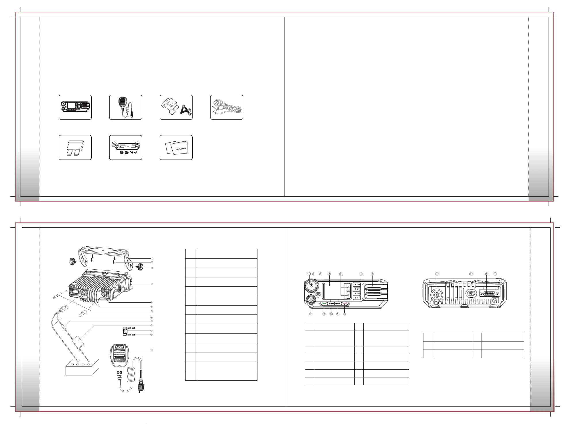
Product Inspection
Please unpack carefully and check that all items listed below are received.
If any item is missing or damaged, please contact your dealer.
Product Inspection
Items
Radio DM-9800
Fuse Mounting Bracket Kit
Palm Microphone
Microphone Hanger
and Screws
User Manual
Power Cord
Before you install the radio in a vehicle, be sure to read
the following instructions carefully:
Instructions
• The radio operates with cathode-grounded power
supply of 13.6V ± 15% only. Please check polarity and
voltage of the power supply on the vehicle before you
install the radio.
Please check how long the screws will extend from
•
the bottom surface of the radio, before you install
the radio. Drill the mounting hole cautiously to avoid
damage to the vehicle wiring and other parts.
Please connect HQT supplied antenna and power
•
cord to the radio, before you install it in the bracket.
And make sure the antenna and power cord is
dedicated for HQT digital radios.
Install the radio with HQT supplied mounting bracket,
•
to avoid radio looseness in case of accidents. The
loose radio may cause bodily injury.
Install the radio in a location where it's easy to reach
•
the front panel controls.
Please make sure there's sufficient space at back
•
of the radio for wiring.
When the fuse for DC power cord needs replacement,
•
it must be replaced by a fuse with the same specification.
Installation Tools
•
Electric drill
•
Cross head screwdriver
•
Hex socket sleeve (used for 4.8*20mm self-tapping
screws)
Installation Steps
A. Install the bracket in a location where it's easy
to operate the radio.
B. C onn ect ac ce sso ries su ch as a ntenn a a nd
power cord to the radio.
C. Slide the radio into the mounting bra ck et and
secure it using the locking knobs.
D. Install the microphone hanger in a location where
it can be reached easily.
E. Plug the palm microphone into the microphone
jack on the front panel (but at first align the triangle
index on the palm microphone with the microphone
installation index), and place it on the hanger when
you do not use it.
03 04
Installation
No.
Mounting Bracket
1
Installation
4.8*20 mm Self-tapping Screws
2
3 Locking Knobs
Radio Unit
4
5
RF Antenna Connector
6 Power Inlet
7
GPS Antenna Connector
8
Black Power Cord
9
Red Power Cord
Fuse
10
11 Microphone Hanger
12 4*16 mm Self-tapping Screws
Palm Microphone
13
Part Name
Radio Overview
Front Panel Rear Panel
No.
1
3
5
7 8
9
11 Sel ect Key 12
Par t Name
Volu me Cont rol/C hanne l
Selector/Power On-Off Knob
Eme rgenc y Key
Up/ Down Ke ys
Spe aker
No.
2 LED I ndica tor
4
6
10
Par t Name
LCD D ispla y
Pro gramm able Ke ys
Bac k Key
Pro gramm able Ke yPro gramm able Ke y
Pal m Micro phone J ack
No.
Part Na me
1 RF Antenna Connecto r 2 Power I nl et
3 A cc essor y Ja ck 4 GPS Antenna Connect or
No.
Part Na me
05 06
Radio Overview

Status Indicators
LCD Icons
Icon Name Icon
Radio Stat us
LED Indicat or
.
Status Indicators
.
.
.
Scanning is in processing.
.
LED Indica to r
flashe s gr ee n
glows re d
glows gr ee n
flashe s or an ge
Radio Stat us
.
GPS Icon
.
Low Tx power for the used chan ne l.
High Tx power for the used cha nn el .
The featur e "Moni to r is activ e."
The speake r is o pe n.
.
The GPS feature is active, and valid GPS data is received.
Operation Mode Icons
Icon Name
Operation Mode Icons
Icon
DM
RM
Operation Mode
Direct Mode Operation: In this mode, radios
communicate with each other directly.
Repeater Mode Operation: In this mode, radios
communicate with each other via a repeater.
07 08
Status Indicators
Programmable Keys
For en hance d conve ni ence, y ou may re quest you r dealer to program the keys P1,P2,P3,P 4, as
shor tcuts t o th e funct ions li sted be lo w:
No.
1
Programmable Keys
2
3
4
5
6
7
8
9
10
11
12
13
14
15
16
17
Shortcut Keys
Non e
Zon e Down
Zon e Up
Sca n
Nui sance Tem po rar y De let e
Eme rgenc y On
Eme rgenc y Off
Adj ust Pow er Leve l
Key pad Loc k
Con tact Li st
Mes sage
Cal l Logs
Adj ust Squ elch Le vel
One Tou ch C all 1
One Tou ch C all 2
One Tou ch C all 3
One Tou ch C all 4
No fe ature wil l be a ss ign ed .
Description
To select a desired zone quickly
To select a desired zone quickly
To receive signals on other channels
To temporarily ignore unwanted channel activity
To summon help in emergent situations
Emergency function is off
To adjust power level
To lock or unlock the keypad
To access the Menu “Contact List” quickly
To access the Menu Message” quickly“
To access the Menu Call Logs” quickly“
To adjust the squelch threshold required for the speaker to unmute
To transmit a call, text message or other service to a preset contact quickly
To transmit a call, message or other service to a preset contact quicklytext
To transmit a call, message or other service to a preset contact quicklytext
To transmit a call, message or other service to a preset contact quicklytext
No.
18
19
20
21
22
23
24
25
26
27
28
29
30
Not e: (1) Diff er ent f un ct ions by your d ea le r.
2 The i s program me d as t he Em er ge nc y key b y de fa ult, an d is p ro gra mm ab le by you r de al er.
( )
Shortcut Keys
One Tou ch C all 5
Squ elch Of f Mo men ta ry
Squ elch Of f
Mon itor
Talk Aro und
Hom e Scree n
Scr amble /Encr ypt
VOX
Lon e Worke r
Roa ming
Opt ion Boa rd
Pho ne List
DTM F Keypa d
can b e assigne d to L on g Pre ss a nd S ho rt Pr es s of a k ey
To transmit a call, text message or other service to a preset contact quickly
Description
To momentarily open the speaker
To always open the speaker
To adjust the condition for incoming signal match
To directly communicate with other radios
To quickly return to the previous menu or home screen
Scramble ( in analog mode):
To encrypt your voice so as to guarantee privacy of your communication
Encrypt :
( in digital mode)
To encrypt your voice so as to guarantee privacy of your communication
To enable or disable the VOX function
To enable or disable the Lone Worker function
To enable or disable the Roaming function
To enable or disable the Option Board function
To access the “Phone List” menu quickly
To access or exit the DTMF Keypad mode. The number input from the radio
keypad is phone number in DTMF Keypad mode.
Programmable Keys
09 10

Basic Operations
Turning the Radio On/Off
To turn the radio on, long press the Power On/Off key
until the radio shows power-up screen and sounds
power-up al ert, and the LED flashes green . To turn
the radio off, press the Power On/Off key.
Basic Operations
Adjusting the Volume
When the Volume Control / Channel Selector knob
op era tes in vol ume ad jus tme nt m ode (t he r adi o
displays th e icon ), rotate the knob cloc kw is e to
increase the ca ll v olu me, or cou nte rclockwise t o
decrease it.
Selecting a Channel
Press the Volume Control / Channel Selector knob to
switch it to channel selection mode (the radio displays
the icon ), and then rotate the knob to select your
desired channel. Alias of the current channel will
appear in the home screen.
Note: The knob is in volume adjustment mode by def ault, and
will retu rn to this mod e in 5 seconds after you sel ect a channe l.
Analog Digital / Switch
Selecting a Zone
A zone is a group of channels exhi biting the same
prope rty, and is progr ammed by your dealer. The
radio supports up to 64 zones, each with a maximum
of 16 channels. You may select a zone through any
of the following methods:
1. Through menu selection
Go to the menu “Zone”, and use the Up/Down keys
to select your desired zone.
2. Through the function keys
You may quickly toggle to your desired zon e by
pressing the programmed Zone Up or Zone Down key.
11 12
Each channel can be programmed as either analog
channel or digital channel. If the current zone includes
both analog and digital channels, you may quickly
switc h b etw een digi tal an d a nal og through the
Channel Selector knob.
Private Call
Transmitting a Private Call
You can ma ke a Private Call through any of the
following methods. When transmitting a Private
Call, the icon will appear.
Transmitting a Call to the Preset Contact
In standby mode, i t will transmit a Private C all to
the c ont a c t (a P riv a t e C a l l n u mber ) p res et fo r
the current channel by .pressing the PTT key
Note: Your dealer may preset a contact for each digital channel.
The preset cont ac t ca n be a Private Call number, a Group Call
number or an All Call number.
Transmitting a Call Through Contact List or Call Logs
1) Go to Contact ->Contact List, or go to Call Logs ->
Call List.
2) Use the Up/Down keys to select your desired
Private Call number.
3) Hold down PTT key to transmit a Private Call
to the selec te d contact.
Transmitting a Call Through Manual Dial
1) Go to Contact -> Manual Dial.
2) Press [#] to enter Private Call input mode, input
a Private Call number you want to call.
3) Press PTT key to transmit a Private Call.
Receiving and Responding to a Private Call
After a Private Call is received, you can respond to it
by pressing the PTT key with in the preset time
period. If you do not respond to it, the ra d io will
display th e missed call icon.
Group Call
Transmitting a Group Call
You c an m ake a C all through any of the
following methods. When transm it ti ng a
Call, th e icon will appear.
Transmitting a Call to the Preset Contact
In st andby mode, it will trans mit a Group Call to
the contact (a Call number) preset for the
current channel by .
Note: Your dealer may preset a cont act for ea ch digita l channe l.
The preset con ta ct ca n b e a Private Call number, a Group Call
number or an All Call number.
Transmitting a Call Through Contact List or Call Logs
1) Go to Contact -> Contact List, or go to Call Logs ->
Call List.
2) Use the Up/Down keys to select your desired
Group Call number.
3) Hold down PTT key to transmit a Group Call to
the selected contact.
Gr oup
Group
Group
pressing the PTT key
Basic Operations
13
Receiving and Responding to a CallGroup
After a Call i s received,
Group you can respond to it
by pressing the PTT key
within the preset time period.
All Call
Menu Navigation
Transmitting an All Call
Methods are th e same as th ose of Tran sm ittin g a
Group Call. When transmitting an All Call, the icon
will appear.
Receiving an All Call
When an All Call is received, your radio will display
the icon.
Making a Call on Analog Channels
To make a call, ho ld dow n [P T T ] k e y a n d sp e a k
into the microphone with normal voice. Please keep
the microphone2.5-5cm away from your mouth.
Menu Navigation
Con ta ct
Messa ge
Call Lo gs
Zon e
Sca n
Set tings
Not ify
Acces so ri es (O pt io nal)
Contact
To access this item, press
the Menu key in idle mode a
nd then select “Contact”.
Contact List
You can save up to 512 entries in the list. To access
this item, select “Contact -> Contact List” or press
the shortcut key for Contact List.
• Editing a Contact
You can edit the number and alias of each Private
Call contact.
• Viewing a Contact
You can view details of each contact.
• Deleting a Contact
You can delete a Private Call contact. However, please
no te that you can not delete the contact when there
is only one entry left in the list. In addition, the private
contact preset on the digital channel cannot be deleted.
New Contact
You can add a Private Call contact to the contact list.
The number and alias of each contact must be unique,
and th e avai l abl e number range is 1-16776415.
Manual Dial
You can manually input the Private/Group Call number
for calling.
Message
To access this item, press the
Menu key in idle mode and
then select “Message”, or
press the shortcut key for
Message directly.
InBox
The InBox can save up to 10 received messages.
When the InBox is full, the icon will appear, and
the oldest entry will be overwritten by the latest
one automatically. For each message, you can choose
to perform any of these operations: Reply, Forward,
View Details and Delete. To del ete all messages
in the InBox, select “Message ->InBox -> Delete
All”.
New Message
You can create your desired text message (128
characters at most) and send it to an individual user
or a talk group.
Quick Text
Under this option there are some text messages (10
entri es at most) preset by your deal er. You can
choose to edit and send any entry.
OutBox
The OutBox can save up to 10 sent messages.
When t h e OutBox is full, the oldest en try will be
overwritten by the latestone automatically.
For each message, you can choose to perform any
of these operations: Reply, Forward and Delete.
To delete all messages in the OutBox, select
“Message->OutBox-> Delete All”
Menu Navigation
14

Drafts
The Drafts can save up to 10 draft mes sages. When
the Drafts is full, the messages will be ov erwri tten
by t h e lat e st one automatically.
For each message, you can choose to perform any
of these operations: Send, Save and Delete.
To delete all messages in the Drafts, select “Message
Menu Navigation
->Drafts ->Delete All”.
Call Logs
To access this item, press the
Menu key in idle mode and
then select “Call Logs”, or press
the shortcut key for Call Logs
directly.
This radio can save up to 10 entries in the Outgoing List,
Incoming List and Missed List respectively. When the
memory for call logs is full, the ol dest entry wi ll be
overw ri tten by the latest one automatically.
After accessing a list and selecting an entry, you can
perform any of these operations: hold down the PTT
key to initiate a call; View Details or delete it.
To delete all entries in Outgoing List, Incoming List or
Missed List at a time, select "Call Logs -> Outgoing/
Incoming / Missed -> Delete All".
15 16
Scan
To access scan, press the
Menu key on home screen
and then select “Scan”.
Scan On/Off
Th e f uncti on “Sc an” al lows y ou to lis ten to
communication activities on oth er chann el s so
th at you c a n keep a c l o s e track of your team
members. This option is used to enable or disable
the function.
Scan List
You can request your dealer to create a scan list
for each channel. Each list may contain 32 channels
at most (eitherdigital channel or analog channel
is OK). After accessing the list, you can perform
any of the following operations:
• Adding a Channel
To include a new channel into the active scan list.
• Editing Priority Channel
To set the selected channel as a non-priority or a
priority channel. If you are interested in activities
on a channel, you can set it as a priority channel which
will be scanned more frequently than a non-priority
channel. Each scan l i s t may contain two priority
channels at most. indicates priority channel 1, and
indicates priority channel 2.
• Deleting a Channel
To remove a channel from the active scan list. However,
the first channel in the list can not be deleted.
Zone
To access this item, press
the Menu key in i dl e mod e
and then select “Zone”.
This radio supports up to 64 zones. You can use this
menu to select your desired zone.
Settings
To access this item, press
the Menu key in idle mode
and then select “Settings”.
You can optimize your radio performance by customizing
related parameters according to actual needs and
your preferences.
Radio Settings
• Language
To set the language in which all interface information
is displayed. Currently, this radio only supports
two languages:Chinese and English.
• Tx Power
This option allows you to set transmit power level.
Alternatively, you can change t h e p o wer le vel
by pressing the shortcut key for Adjust Powe r
Level in id le mode.
There are two levels available: High (indicated by )
and Low (indicated by ). High power level enables
you to communicate with farther team members.
Note: Power level should be set for each channel individually.
• Lone Worker
This function can trigger off the Emergency mode
if the radio does not work for a certain time period.
This parameter determines whether to enable the
Lone Worker func tion.
Menu Navigation
• Tone
To set tones for your radio. You can set the following tones:
Radio Silent: to set whether the radio will give tone
indication. If Silent On is selected, all alerts will be off.
Call End Tone: to set whether the radio will give tone
indication when the call ends.
Private Call Tone: to set whether the radio will give
Menu Navigation
tone indication when the radio receives a private call.
Text Message Tone: to set whether the radio will give
tone indication when the radio receives a message.
Keypad Tone: to set whether the radio will give tone
indication when you are making keypad operations.
Group Call Tone: to set whether the radio will give
tone indication when the radio receives a group call.
Signaling Side Tone: to set whether the radio wil l
give tone indication when PTT is pressed (during
transmission of PTT ID);
• Squelch
This option allows you to select an appropriate squelch
level. Alternatively, you can change the squelch level by
pressing the shortcut key for Adjust Squelch Level in the
home screen.
There are three levels available: Tight, Normal and Open.
The default squelch level is “Normal”, and is often used in
low noise environment.
17 18
An d gen era lly, “ Ti ght ” is us ed in hi gh no ise
environment. It requires stronger signal for the
radio to unmute. However, if the squelch level
is set to Open, the speaker wil l keep unmuted
irrespective of t he decodin g conditions.
• Scr am bl er /En cr yp t
To set whether to enable the Scrambler/Encrypt
feature.
• LED
All LEDs: to enable /disable all LED indications.
TX LED: to set whethe r th e Tx LED indicat es
during
RX LED : to set whether the Rx L ED i ndi cat es
du rin g re cep tio n.
Scan LED: to set whether the Scan LED indicates
in Scan mode.
Carrier LED: to set whether the Carrier LED indicates
when receiving carrier.
• VOX
On/Off
If “On” is selected, it allows the user to make calls
every time the user speaks into the radio directly
without pressing the PTT key.
transmission.
If “Off” is selected, the user should make calls by
pressing the PTT key.
Gain Level
The range of “Gain Level” is Level 1 to Level 9. The
lower the Gain Level is, the easier the VOX to be
enabled.
• Radio Password
Options: Off / On
When “On” is selected, users have to input the correct
Radio Lock Password to operate the radio normally.
When “Off” is selected, users can operate the radio
without inputting the password.
Radio Info
With this option, you can view the basic information
of your radio, including Serial Number, Radio Alias,
Frequency Range, Firmware Ver, Radio Data Ver and
Last Programmed Date.
Accessories
To access this item, press the
Menu key in idle mode and
then select “Accessories”.
GPS(Optional)
Operation:
1. To enable the feature:
Go to “Main Menu-> Accessories->GPS On/Off->
Off or On” and select “On”.
2. To disable the feature:
Go to “Main Menu->
Accessories->GPS On
/Off->Off or On” and select
“Off”
• Position
With this option, you can view longitude, latitude,
time, date, speed, altit ude and SA (s atell ite)
information of your radio.
• Time Zone
Users can select a desired time zon e fr om th e
dr o p -down li s t. Th e ra d i o ad j u s t s i t s tim e
according to the selected time zone.
• GPS Update Time
Th is op tio n def ines th e time interval to update
the GPS information. Range:1 – 60 seconds.
Menu Navigation

Functions and Operations
Phenomena Analysis Solution
The radio can not be powered
on.
The power cord may be
unconnected.
Connect the power cord
correctly.
The vo lume may be set to a
low level.
Increase the volume by
rotating the Volume Control
knob clockwise.
The antenna may get loose or
may be improperly installed.
Power off the radio, re-install
the antenna and power on
the radio again.
During receiving signals, the
voice is weak, discontinuous
or totally inactive.
The speaker may be blocked
or damaged.
Clean surface of the speaker.
If the problem can not be
solved, contact your dealer or
our authorized ser vice center
for inspection and repair.
The frequency or signaling
may be inconsistent with that
of other members.
Set your TX/RX frequency
and signaling to the same as
that of other members. You can not com municate
with other members in Analog
mode.
You may be too far away
from the group members.
Move towards other
members. And make sure
that you are within the
communication range.
You can not com municate
with other m embers in Digital
mode although there is
receiving indication.
Your ID may be inconsistent
with that of other members.
Consequently, the digital
carrier can be received but
can not be demodulated.
Set your ID to the same as
that of other members.
You may be interrupted by
radios using the same
frequency.
Adjust the squelch level.
Irrelevant communications or
noises are heard on the
analog channel.
The radio may be set with no
signaling.
Set your radio with signaling
to avoid interference at the
same frequency, and make
sure that all members share
the same signaling.
Home Screen
The feature allows you to quickly return to the previous
menu or the home screen.
Operation:
Press the [Option] Key on the editing screen, then
the radio exits the screen and returns to the previous
menu immediately;
Functions and Operations
Press the [Option] Key on other screens, then the
radio returns to the home screen.
Talk Around
You can continue communicating in DM mode by
pressing the programmed Talk Around key, when
your repeater malfunctions, or when your terminal
is out of the repeater’s range but within the talk range
of other terminals.
Operation:
Press the programmed Talk Around key to switch
between DM mode and RM mode.
Monitor
To adjust match co nditions for si gnal receiving,
you can enable the feature “Monitor”.
Operation:
• Press the programmed Monitor key to enable
the feature, and the radio displays the icon .
To d
isable the feature, press this key again.
Squelch Off
If the feature “Squelch Off” is enabled, your radio’s
spea ker will keep unmuted no mat ter w h ethe r
ca r rie r is present.
Operation:
• Pre ss t he programmed Squelch Off key to
enable the feature. Then the radio displays the
icon a n d s o u n ds bac kgr ou nd n ois e. To
disab le the feature, press this key again.
• Press the programmed Squelch Off Momentary
key to enable the feature. Then the radio displays
the ic on a n d s ounds backgrou nd noise. To
disa ble the feature, release this key.
Digital Emergency
Emergency Alarm with Voice to Follow Operation:
1. Press the programmed Emergency key to go to the
Emergency Revert Channel, and the radio displ ays
the icon .
2. When the ico n app ear s , you ca n s peak i nto the
microphone to make an emergency call.
3. When the icon appears, your radio is receiving. When
a call is received, the icon appears. If the preset voice
cyc les expire, you can press the PTT k ey t o make
the emergency call again (the radio displays the icon
with LED glow ing red).
Afte r th e em ergen cy c all i s tr ansmi tted, please
release the PTT key to receive (the radio displays the
icon). When a call is received, the icon appears. To exit
the Emergency mode, long press the programmed
Emergency key.
Note: Your dealer may set the time of voice cycles, duration of each
transmission and Tx interval.
Busy Channel Lockout
If enabled via the programm ing soft ware , th is
feature can prevent your radio interfering with other
transmitting terminals on the same channel. If you
hold down the PTT key while the channel is in use,
your radio will keep beepi ng an d d isp l ay t ext
in f orm a tio n “Chan n e l Busy”, a l e r t ing y o u t o
transmission prohibition. To stop the beep, please
relea se the PTT key. When the channel is free,
yo u ca n press an d hold down the PTT key to
trans mi t.
Time-out Timer (TOT)
The purpose of TOT is to prevent a ny user from
occupying a channel for an extended period.
If the preset time expires, the radio will automatically
terminate transmission and keep be eping.
To st o p the beep, please release the PTT key.
You must wait for a certa in time period (prese t
by your d ealer) before you can press and hold
down the PTT key to transmit again. If the pre-alert
function is set by your dealer, your radio will alert
you to the TOT expiration in advance.
Note: This feature is null in Emergency mode.
19 20
Functions and Operations
Invalid Channel Indication
If the current operating channel is invalid, the radio
will send continuous “Dududu” as alert tone, whic h
means the current channel is unable to transmit or
receive.
Optional Accessories
Squelch
The squelch level decides how strong the signal is to
unmute the speaker. The lower the squelch level is, the
stronger the background noise is to unmute the speaker.
The larger the talk range is, the weaker the Rx anti-
21 22
interference ability is. Setting range is 0~9, it causes
the squelch to open by selecting “0”. T he higher the
squelch level is, the harder to open the squelch.
Optional Accessories
Optional accessories and replacement parts are
available through your Authorized Dealer.
Those items include:
VHF Antenna
UHF Antenna
GPS Antenna
DTMF Microphone
Programming Cable
Programming Software
Troubleshooting
Troubleshooting

You may be too far away from
other members.
You may be at an unfavorable
position. For example, your
communication may be
The noise is too loud.
Care and Cleaning
You can not use the keys.
There is no display.
The GPS cannot locate your
position.
If the above solutions can not fix your prob lems , or you may
hav e some other que ries, p le as e co nt ac t us o r yo ur local
dea ler for more tec hnica l suppor t.
blocked by high buildings or
frustrated in the undergrou nd
areas.
You may suffer from external
disturbance (such as
electromagnetic interference).
The ke ypad may f ail to
function temporarily.
The LCD may fail to function
temporarily.
The GPS antenna is
improperly connected.
No GPS signal is received.
Move to wards other
members, and then try again.
Move to an open and flat
area, and try again.
Stay away from equipment
that may cause interference.
Restart the radio.
Restart the radio.
Connect the GPS antenna
correctly.
Move to an open and flat
area, and restart the radio.
Care and Cleaning
To guarant ee o pt im al p er fo rm an ce a s we ll as a long
service life of the product, ple ase foll ow the tips below.
Product Care
• Kee p t he pr odu ct at a pla ce wi th goo d v en til ati on
and heat dis si pa ti on t o fa ci li ta te n or mal work.
Do not plac e irr ele vant artic les on top of th e produc t
•
to ensur e op ti ma l he at d is si pa ti on .
Do not place the product in corrosive agents, solutions
•
or water.
Product Cleaning
Clean up t he d us t an d fi ne p ar ti cl es o n th e product
•
parts with a c le an a nd d ry l in t- fr ee c lo th o r a br ush
regula rl y.
•
Use a non-woven fabric with neut ral clea nser to clean
th e k ey s , con tro l k no bs, LCD and jacks after lo ng tim e use. Do not us e che mical pr epara tions su ch as
stain remo ve rs , al co ho l, spra ys or oi l pre paration s.
Mak e sure the produ ct is complet ely dry befor e use.
Caution: P ow er o ff the produ ct b ef or e cl ea ni ng .
Service and Support
Shen zhen HQ T Science & Technolo gy Co., Ltd.
(“HQT”) provides long-term support for its products,
including repair and supply of the radio and its parts
and accessories.
Ser vice Comm itment
1. HQT two-way radio body has an 18-month warranty;
accessories: 6 months.
2. Free repair is available and subject to the fully-filled
warranty card or valid original invoice of purchase
in the case that the radio or accessories can not
work normall y due to non-h uman fac tor d ur ing
the warranty period .
3. Replaceme nt or repair is availab le and subject
to the fully-filled warran ty card or valid origin al
invoice of purchase in the case that the radio or
acc essories can not work normally because of
non-human fa ctor wi thin 30 days from the date
of purchase.
4. Repaired parts are warranted for the balance of
the original applicable warranty period or 90 days
fro m the date of repair. The longer one is valid.
Warran ty
1. Th e warra nt y is only val i d f or p rod ucts un d er
factors are excluded from the warranty coverage.
Such as: disassembling or modifications, damages
cau sed by outsi de fo rce, water pe netra tion,
bur ns, use of HQT unapp roved accessor ies,
usin g again st the user m anual a nd so on.
2. The war ranty p er iod sta rts fro m the dat e of
purc hase on t he i nvoic e.
3. Fre e repai r is unavaila ble if the HQT mark or
seri al numb er labe l is t orn off.
4. Onl y the ful ly -fill ed warr anty ca rd a nd vali d
orig inal in voice o f purch ase with HQT's se al
or autho rized d ealer 's s eal a ffi xed are va lid
fo r receiv ing the w arran ty s ervic e.
Caut ions
1. Rea d the use r ma nual be fore us e.
2. Do not use the radi o wit h dam aged antenna,
only H QT approv ed a ntenn a is appl icabl e.
3. Turn o ff t he radi o in p otent ially e xplos iv e or
flam mable e nviro nm ents.
4. Do not immerse the radio into liquids or discard
it in fi re.
5. Use the radio only with standard accessories.
normal use, defects or damages resulting from human
23 24
Service and Support
Terms of Warran ty
1. H QT tw o-w ay ra di o b od y h as an 1 8-m ont h war ran ty ;
accessor ie s: 6 m ont hs .
2. O nly t he fu l ly -fi lle d war ra n ty ca r d a n d v a lid or i gin a l
invoice of purchase with HQT's seal or authorized dealer's
seal affixed are valid as proofs for identifying the warranty
period. (The invoice should give clear indi cation of radio,
acc essories , serial nu mber, date of purc has e, purch ase
pr ice a nd so o n .)
3. If the radio body goes wrong during the wa rrant y peri od,
Service and Support
it sho uld be ensu red wo rking normally over 30 days after
th e rep air.
4. R epl ace me n t or re pai r is avail ab le and subje ct to the
fu lly -f i ll ed wa rra nty c ard a nd va lid o rig ina l in vo ic e of
purchase in the case that the radio can not work normally
as t he in str uct ion s li st wit hi n 30 da ys fro m the d ate o f
pu rch as e . (N o te t h at th er e m us t n ot be a bra sio ns on
ra dio b ody a nd ac ces sor ie s .)
5. Replacement of the same model is available and subject
to the 3 re pa ir r ec ei pt s in the ca se t ha t the r adi o bod y
st ill w ork s abn orm al ly af t er 3- t ime - o r- a b ove re p a irs
8. No warranty servic e is provide d if the HQT mark and/
or serial number la bel on the pr oduct ar e/is torn off.
9. Exclu si on s fr om w ar ra nt y co ve ra ge:
1)Beyond t he v al id w ar ra nt y pe ri od ;
2)Defects or damages that result from use of the product
in other tha n it s no rm al a nd c us to ma ry m an ner;
3)Defects or damages resulting from misuse, accident,
water pene tr at io n or n eg le ct ;
4)De fec ts or da mag es caused by im pr op er t es ti ng ,
op era ti o n, re pai r, i nst al l at ion , reconfigu ra ti on o r
adjustme nt ;
5)Defects or d am ag es t o ant enna unless caused by
material o r pr oc es si ng p ro bl em s;
6)Pr o duc t wh i c h h a s t h e s eria l nu mber r e m o v ed
or il le gible;
7)Produc t wi th u nc le ar d at e of p ur ch as e;
8)Defects or damages becau se of unauthorized repair
or disas se mb li ng ;
9)Abrasi on s un de r no rm al u se .
Warning!
The antenna of this device must be installed on the roof or trunk of the vehicle. Maximum
the gain of the antenna is 3.5dBi, the minimum operating separation distance
Rsafe =66cm. This distance must be maintained during normal operations to the user.
du rin g the w arr ant y per io d .
6. R epair of the radi o and ac ce ssories i s a va i la ble a nd
su bje ct to t he va lid o rig ina l inv oic e of pu rch as e .
7. T he co sts o f mat eri al s a nd re pai r are c ove red d uri ng
th e war ran ty pe rio d.
Note: Th is wa rr ant y wil l be ad j us te d o r m od if i ed p r op er l y acc or di n g to th e m ar ket , and i t is s ub je ct to ch ange wi th ou t
notice. I f ad ju st ed o r mo di fi ed, the war ra nt y is s ub je ct t o th e latest vers io n is su ed b y HQ T service cent er i n HQT off ic ial
channel s.
25 26
 Loading...