

HQT DM-9800 User Manual
Thank you for purchasing HQT DMR Digital Mobile Radio DM-9800.
As a product built to the DMR standard, DM-9800 is endowed with ergonomic design,
all-round digital functions and remarkable quality t o increase your managemen t
efficiency and enable you to be responsive to emergent situations.
To derive optimum performance from your product, please read this manual carefully
before use.
Preface
SHE NZHEN H QT SCIE NC E & TE CH NO LO GY C O LTD., .
For m ore inf ormat ion, pl ease vi sit www .hq tsolu tions .com
All ri ghts re serve d to HQT. P ictur es show n in this m anual a re for yo ur refe rence o nly,
if the re is flu ctuat ion, pl ease ta ke the ma teria l objec t as the st andar d.
DM-9800
DIG ITAL MO BILE RA DIO
HQT endeavors to achieve the accuracy and completenes s of this manual. As for
any inaccuracies and omiss io ns tha t m ay pos si bl y occu r, t he r i gh t t o in ter pre t
is reserved to Shenzhen HQT Science&Technology Co., Ltd.
The design and specifications of this product are subject to being modified by Shenzhen
HQT Science&Technology Co., Ltd. without prior notice.
It is pr ohibite d to copy, tr ans mit , ex cerpt an d s tor e t hi s manu al in any retrieval
system , or translate it to any lan gua ge wi tho ut written authoriza tion of HQT.
Statement
FCC Caution
01 02
Contents
Contents
04
04
04
04
06
06
06
07
03
Front Panel
Rear Panel
Status Indicators
LCD Icons
LED Indicator
Programmable Keys
Basic Operations
11
Adjusting the Volume
11
Selecting a Zone
11
Selecting a Channel
11
Analog/Digital Switch
11
Private Call
11
Group Call
12
13
All Call
13
Making a Call on Analog Channels
13
Menu Navigation
13
Contact
14
Message
15
Call Logs
15
Scan
Zone
16
Settings
16
Accessories
18
Functions and Operations
19
Home Screen
19
Monitor
19
Squelch Off
19
20
Digital Emergency
20
Busy Channel Lockout
21
Invalid Channel Indication
21
Squelch
21
Optional Accessories
Troubleshooting
Care and Cleaning
Service and Support
07
08
09
Contents
Product Inspection
Installation
Instructions
Installation Tools
Installation Steps
Radio Overview
20
Time-out Timer (TOT)
Turning the Radio On/Off
11
Talk Around
19
Any Changes or modifications not expressly approved by the party responsible for compliance could void the user's
authority to operate the equipment. This device complies with part 15 of the FCC Rules. Operation is subject to the
following two conditions: (1) This device may not cause harmful interference, and (2) this device must accept any
interference received, including interference that may cause undesired operation. Your radio radiates measurable RF
energy only while it is transmitting(during talking), not when it is receiving(listening)or in standby mode. Antenna gain must
not exceed 3.5 dBi.The antenna installation comply with the requirements of manufacturer or supplier, and at least 3.8m from
any body part of the user or nearby persons.
Your 2-way radio is designed and tested to comply with a number
of nation al and international standards and guidelines (listed below) for human expos ure to radio frequ ency
electromagnetic. This radio complies with the IEEE and ICNIRP exposure limits for occupational/controlled RF
exposure environment at operating duty factors of up to 50% transmitting and is authorized by the FCC for occupational use
only. In terms of measurable RF energy only while it is transmitting (during talking), not when it is receiving (listening) or in
standby mode.
Note: The approved batteries supplied with this radio are rated for a 5-5-90 duty factor (5% talk -5% listen -90% standby)
even though this radio complies with the FCC occupational RF exposur e limits and may operate at duty factors of
up to 50% talk.
Your Shenzhen HQT Science & Technology CO.,LTD. Two-way radio complies with the following RF energy exposure
standards and guidelines:United States Federal Communications Commission, Code of Federal Regulations; 47CFR
§§1.1.307,1.1310,
Shenzhen HQT Science & Technology CO.,LTD.
FCC Caution
• 2.1091 and 2.1093
American National Standards Institute(ANSI)/ Institute of Electrical and Electronic Engineers (IEEE) C95.1-1992
Institute of Electrical and Electronic Engineers (IEEE) C95.1-1999 Edition
•
•
Warning! : This radio generates RF electromagnetic energy during transmit mode. This radio is
designed for and classified as “Occupational Use Only,” meaning it must be used only during the
course of employment by individuals aware of the hazards and the ways to minimize such hazards.
This radio is NOT intended for use by the “General Population” in an uncontrolled environment.
RF Specification:
Frequency range:400-470MHz
RF output power: High power 50W / Low power 25W
Modulation Type:Analog :FM / Digital: 4FSK
Channel Separation: 12.5kHz
22
23
24
FCC Caution
03 04
Installation
05 06
Radio Overview
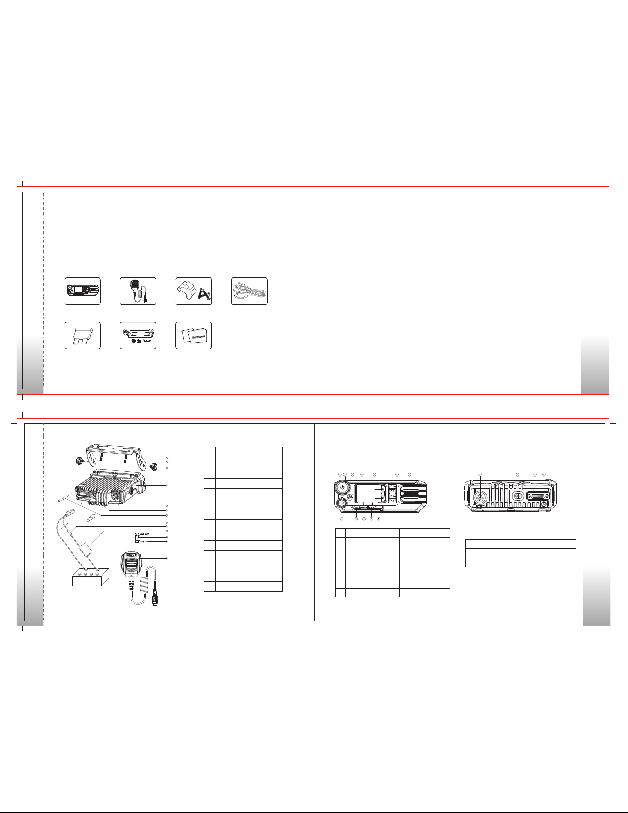
Please unpack carefully and check that all items listed below are received.
If any item is missing or damaged, please contact your dealer.
Product Inspection
Items
Microphone Hanger
and Screws
Power Cord
Palm Microphone
Fuse Mounting Bracket Kit
Radio DM-9800
User Manual
Before you install the radio in a vehicle, be sure to read
the following instructions carefully:
A. Instal l the bracket in a location where it's easy
to operate the radio.
B. Conne ct acc esso ries su ch as ant enna a nd
power cord to the radio.
C. Slide the radio into the moun ting brack et and
secure it using the lockin g knobs.
D. Install the microphone hanger in a location where
it can be reached easily.
E. Plug the palm microphone into the microphone
jack on the front panel (but at first align the triangle
index on the palm microphone with the microphone
installation index), and place it on the hanger when
you do not use it.
Installation
Instructions
• The radio operates with cathode-gr ounded power
supply of 13.6V ± 15% only. Please check polarity and
voltage of the power supply on the vehicle before you
install the radio.
Please check how long the screws will extend from
the bottom sur face of the radio , before you insta ll
the radio. Drill the mounting hole cautiously to avoid
damage to the vehicle wiring and other parts.
Please connect HQT supplied antenna and power
cord to the radio, before you install it in the bracket.
And make sure the antenna and pow er cord is
dedicate d for HQT digital radios.
Install the radio with HQT supplied mounting bracket,
to avoid radio looseness in case of accidents. The
loose radio may cause bodily injury.
Install the radio in a location where it's easy to reach
the front panel controls.
Please make sure there's sufficient space at back
of the radio for wiring.
When the fuse for DC power cord needs replacement,
it must be replaced by a fuse with the same specification.
•
•
•
•
•
•
Installation Tools
•
•
•
Electric drill
Cross head screwdriver
Hex socket sleeve (used for 4.8*20mm self-tapping
screws)
Installation Steps
No.
Par t Name
1
Rad io Unit
2
RF Ant enna Co nnect or
3 Loc king Kn obs
4
Mou nting B racke t
5
4.8*20 mm Self -tapping Screw s
6 Pow er Inle t
7
Bla ck Powe r Cord
8
Red P ower Co rd
9
Fus e
10
Pal m Micro phone
11 Mic ropho ne Hang er
12 4 *16 mm Se lf-ta pping S crews
13
GPS An tenna C onnec tor
Radio Overview
No. Part N ame No. Part N ame
1
Volum e Contr ol/Ch annel
Selector/Power On-Off Knob
2 LED In dicat or
3
LCD Di splay
4
5
Back K ey
6
7 8
Up/D own Key s
9
Spea ker
10
Prog ramma ble Key s
11 S elect K ey 12
Front Panel Rear Panel
No. Part N ame No. Part N ame
1 RF Antenna Connec tor 2 Powe r Inlet
3 Acce ssory J ack 4 GPS Anten na Connector
Emer gency K ey
Prog ramma ble KeyProg ramma ble Key
Palm M icrop hone Ja ck
Product Inspection
Installation
 Loading...