

Page 1
User Manual
Versio n : V 1.01
The above information is subject to change without prior notice.
Dear users
Thank you for choosing our product. Before using the product, please
read this manual carefully.
1. Automatic system voltage identification
2. Charging program options for sealed, GEL and flooded lead-acid batteries and lithium batteries
are available.
3. An upgraded 3-stage PWM charging algorithm is adopted. Application of an equalizing charge
to the battery periodically or when over discharged can effectively prevent the battery from nonequalization and sulfuration, thus extending the battery's service life (with the exception of GEL
and lithium batteries).
4. With temperature compensation employed, charging parameters can be automatically adjusted
(with the exception of lithium batteries).
5. A wide range of load working modes facilitate the product's application to different types of
street lights and monitoring devices.
6. The product provides overcharge, over-discharge, overload protection, as well as short-circuit
and reverse-connection protection.
7. By virtue of an advanced load starting method, large-capacitance loads can be started
smoothly.
8. A range of parameter settings and power-down saving functions are available, thus requiring no
repeated setting.
9. The product provides a dot matrix graphic LCD screen and a human-machine interface with 2
keys.
10. The user-friendly design of browser and dynamic interfaces ensures convenient and intuitive
operations.
11. (An optional communication function) provides a RJ12 data port (output of TTL232 level or
bluetooth signals), with the data adopting the standard Modbus protocol, and can be used
together with our upper computer monitoring software or mobile phone APP.
12. Boasting an industrial grade design, the product can function well in various tough conditions.
13. It features a backlit display, and the backlight will be turned on with a key pressed and turned
off over a period of time.
14. TVS lighting protection is adopted.
Pro duct Fe atures
Pane l Struc ture
Stat e Indic ators Five L oad Wor king Mo des
(
PWM 30A/PWM 40A
)
1.Pure light control (0): When sunlight disappears and the light intensity drops to
the starting point (light control off), the controller initiates a 10-minute delay
(settable) to confirm the starting signal, and then switches on the load for operation.
When sunlight emerges and the light intensity reaches the starting point, the
controller initiates a 1-minute (fixed) delay to confirm the shutting-down signal, and
then shuts down the output to stop the load's operation.
2. Light control + time control (1 to 14): The starting process is the same as pure
light control. After operating for a preset period of time (settable from 1 to 14 hours),
the load stops operation automatically.
3. Manual mode (15): In this mode, the user can switch the load on or off by the
keys,no matter whether it's day or night.
4. Debugging mode (16): When the solar panel voltage is higher than the "light
control off" voltage, switch off the load immediately; when the solar panel voltage is
lower than the "light control on" voltage, switch on the load immediately.
5. Normal on (17): The energized load keeps in output state.
Load W orkin g Mode Se tting s
In the load mode menu, long press for 2s, and the number (e.g. 15) will begin to flash.
Press to adjust the mode (from 0 to 17), and then long press again for 2s to complete
and save the setting.
Note: 1. After parameter adjustment, if is not pressed and held long enough for
exiting, the system exits to the main menu after 12s, and the parameter that
was set is not saved.
2. When the system is saving data, the screen may shake slightly. This is normal
and the user may ignore it.
Saf ety Adv ice
1) When connected to a 24 V system, the solar panel terminal voltage may exceed the
limit for human safety. If operation is to be performed, be sure to use insulation tools
and keep your hands dry.
2) If the battery is reversely connected, the controller itself won't be damaged, but the
load end will have a negative voltage output, which may damage your load device.
Take care not to let this happen.
3) The battery contains a large amount of energy. Therefore, in no cases should the
battery be short circuited. It's recommended that a fuse be serially connected to the
battery.
4) Keep the battery away from fire sparks, as the battery may produce flammable gas.
5) Keep children away from the battery and controller.
6) Follow the safety advice provided by the battery manufacturer.
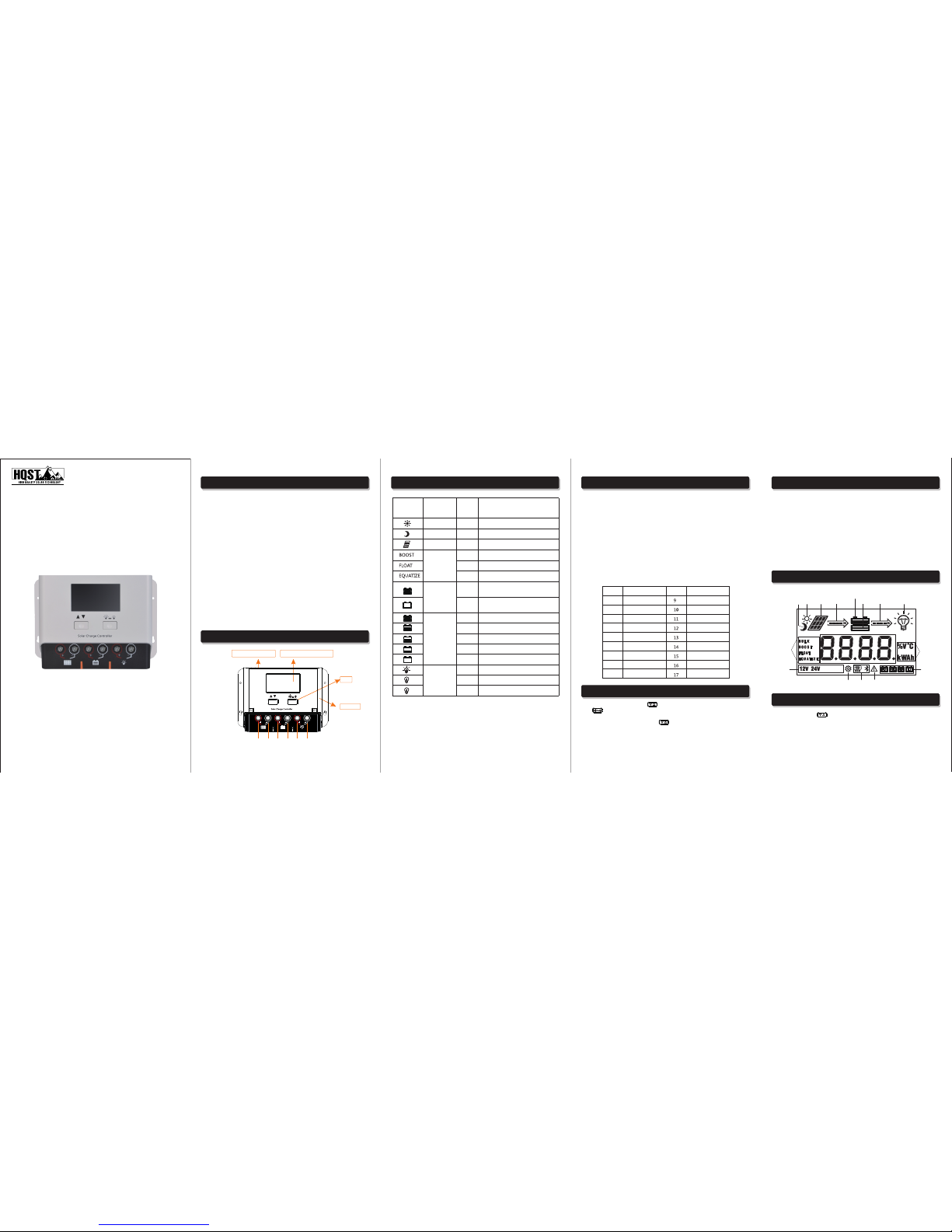
LCD Sc reen Il lustr ation
Bro wsing Me nu on LCD S creen
Communication port
LCD screen with backlight
USB port
Solar panel
Batter y
Load
Keys
-+-
+-+
LCD Icon
Indicated
Object
State Meaning
Day recognition
Night
recognition
Solar panel
Charging state
Battery
Battery SOC
Load
Steady on
Steady on
Steady on
Steady on
Steady on
Steady on
Quick
flashing
Slow
flashing
4 dashes
3 dashes
2 dashes
1 dash
0 dash
Steady on
Steady on
Quick
flashing
Day time
Night time
Solar panel indication
Boost charging
Floating charging
Equalizing charging
Battery overvoltage
Battery over discharge
100%
75%
50%
25%
0%
Load turned on
Load turned off
Overload or short-circuit protection
LED
Display
Mode
LED
Display
Mode
Pure light control mode
Light control + time
control (1 hour)
Light control + time
control (2 hour)
Light control + time
control (3 hours)
Light control + time
control (4 hours)
Light control + time
control (5 hours)
Light control + time
control (6 hours)
Light control + time
control (7 hours)
Light control + time
control (8 hours)
0
1
2
3
4
5
6
7
8
Light control + time
control (9 hours)
Light control + time
control (10 hours)
Light control + time
control (11 hours)
Light control + time
control (12 hours)
Light control + time
control (13 hours)
Light control + time
control (14 hours)
Manual mode
Debugging mode(default)
Normal on mode
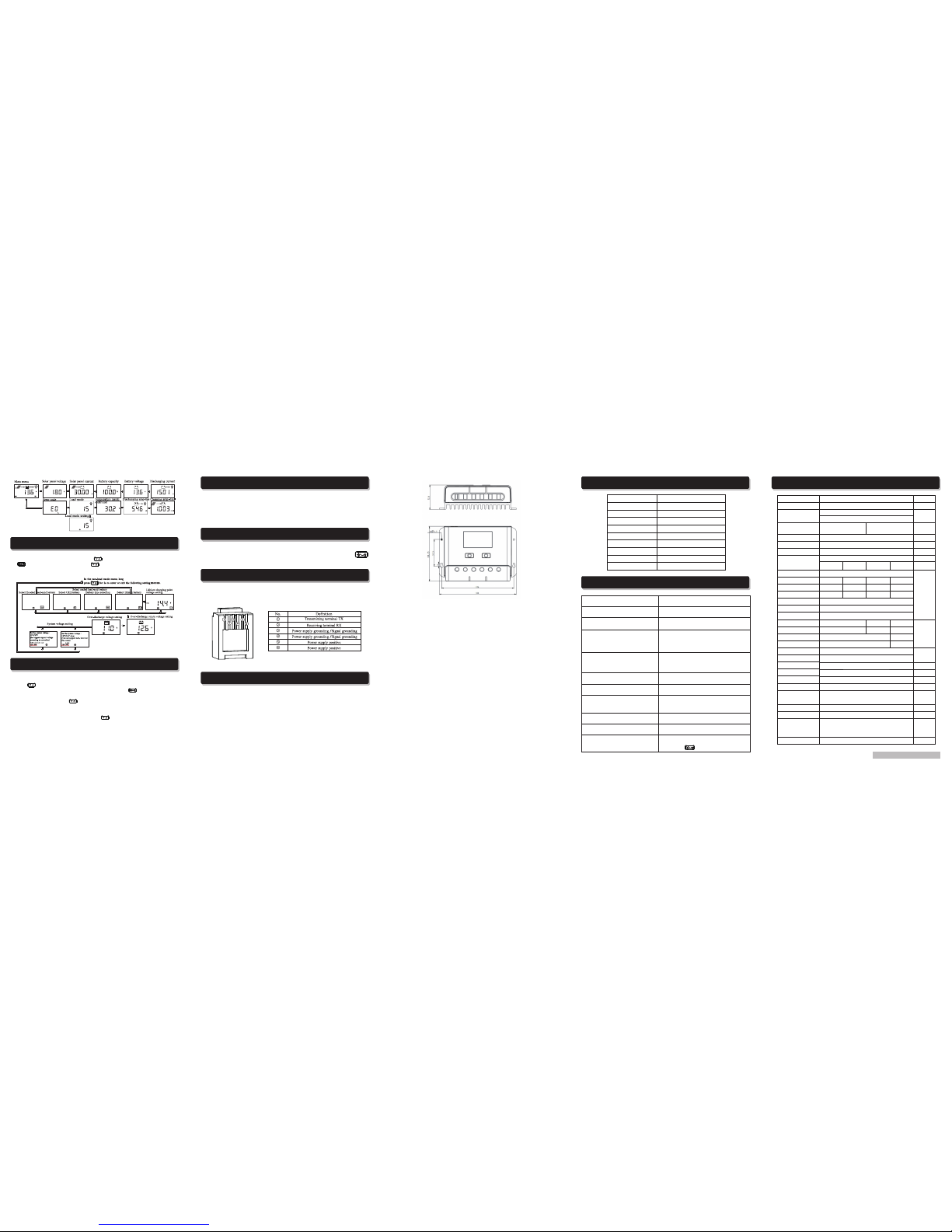
1).Continuously press ,the screen will display the following in order: "main
menu"---"solar panel voltage"---" solar panel current"---"battery capacity"---"battery
voltage"---"discharging current"---"charging amp-hrs"---" discharging amp-hrs"---"
temperature inside controller"---" load mode"---" load mode settings"---"error code",
and then back to "main menu". If the keys are not operated for 12s, the system will
automatically return to display the "main menu".
36V4 8V
Discharging
SOC
indicator
current
indicator
Load
indicator
Night time
indicator
Daytime
indicator
Solarpanel
indicator
Chargingcurrent
indicator
Battery
indicator
Units
Battery
type
Fault
indication
Mode
settings
Data
communication
method
System
voltage
Charging
state
Numerical value display area
solar charge controller
HQST PWM CONTROLLER
Page 2
Parameter Details
Material Code:1.1.24.01511
Set ting Me nu on LCD Sc reen
2). When "load mode" is displayed, long press to enter into the load mode setting. Press
to adjust the mode, and long press for 2s to save and exit; or else, the system
will not save the setting that was just made and automatically exit the setting interface after 12s.
Batte ry Type s, Char ging Vol tages ( Lithi um Batt ery)
Over-D ischa rge Ret urn and O ver-Dis charg e Voltag e Setti ngs
In the non-load mode menu:
1) When is long pressed, the first interface entered is for battery type setting, and
the flashing one is the battery type currently selected. Press to select among
FLD/GEL/SLD/LI.
2) After selection, short press to enter into over-discharge return and overdischarge voltage settings; or the first to enter charging voltage setting menu for
lithium battery.
3) After parameters have been set, long press for 2 s to save and exit.
Parameters shall be set according to the following rule: over-discharge voltage<
over-discharge return voltage ≤under-voltage warning<floating charging
voltage<boost charging return ≤equalizing charging voltage<overcharge
voltage; and two adjacent values shall have a difference greater than 0.5 V.
In the charging and discharging overload protection mechanism, the relation between
overload current and protection time is as follows: An overload current 1.25 times of
the rated current initiates a delay of 30s before starting protection; similarly, 1.5 times,
5s and 2 times, 1s.
Overload recovery: automatic recovery after 1 minute.
Charging and Discharging Overload Protection and Recovery Time
Short-circuit automatic recovery time: 1st time, 5 s; 2nd time, 10 s; 3rd time, 15 s; 4th
time, 20 s; 5th time, 4 hours or automatic recovery the next day; or long press
to make the load resume output.
Load S hort C ircui t and Reco very
Comm unica tion Por t Line S equen ce
(Only f or Cont rolle rs with C ommun icati on Func tions )
Controller communication port RJ12 (6-pin)
RS232
Installation Instructions and Precautions
1. The controller shall be installed securely, and its dimensions
are as follows:
PWM-30A/40A External dimensions: 166.0×118.2×52.6(mm)
Installation dimensions: 156×57.5 (mm)
3. Precautions:
①If it is 12V system, the bottom left corner of LCD display will show '12V'; 24V system
will show' 24V'.
② The first step is to connect the battery. If the connection is made correctly, the
controller screen will be lit up; otherwise, check whether the connection is correct.
③ The second step is to connect the solar panel. If sunlight is present and strong
enough (the solar panel voltage is greater than battery voltage), the sun icon on the
LCD screen is on; otherwise, check whether the connection is correct (it's
recommended that the operation be performed under the debugging mode).
④ The third step is to connect the load. Connect the load leads to the controller's
load output terminal, and the current shall not exceed the controller's rated current.
⑤As the controller will generate heat during operation, it's recommended that the
controller be installed in an environment with good ventilation conditions.
⑥ Choose cables with large enough capacity for connection, in case too much loss
incurred on the lines causes the controller to misjudge.
⑦The controller has a common negative pole inside. If grounding is needed, ground
the negative pole.
⑧It's important to fully charge the battery regularly. At least once full charging every
month is recommended, and failure to do that may cause permanent damage to the
battery. Only when in-flow energy outpaces out-flow energy can the battery be
charged fully. Users shall bear this in mind when configuring the system.
⑨ Check whether the controller's each connection terminal is tightened securely; if
not, it may suffer damage when large current passes.
PWM-30A/PWM-40A
Erro r Code Li st
Corresponding error
Code on LCD screen
E0
E1
E2
E3
E4
E5
E6
E8
E10
No error
Battery over discharge
Battery overvoltage
Undervoltage warning
Load short circuit
Load overload
Temperature too high inside controller
Charging current too high
Solar panel input voltage is too high
Common Problems and Solutions
Causes and Solutions
Check whether the battery is correctly
connected.
Check whether the ambient temperature is
too low and whether the display recovers
when the temperature rises.
Check whether the solar panel is correctly
connected and contact is good and reliable.
Check whether the solar panel voltage falls
below the battery voltage.
The load will be switched on automatically
after 10 minutes (set by the user).
System overvoltage. Check whether the
battery voltage is too high.
The battery is over-discharged, and will
recover when recharged adequately.
The load's power exceeds the rated value or
it's short-circuited. After removing the problem,
long press the key or wait until it recovers
automatically.
Check whether the power-consuming device is
connected correctly and reliably.
Check whether wiring is sound and reliable, and
system voltage is correctly recognized.
Symptoms
LCD screen does not light up
Incom plete d ispla y or no ren ewal
on LCD sc reen
No charging with sunlight present
The battery icon flashes slowly,
and there is no output.
The load icon flashes quickly, and
there is no output.
The load and the encircling light ring
stays lit, and there is no output.
Other symptoms
The charging and discharging amp
-hrs displays: 9999.K Ah
The decimal point flashes indicating that the
displayed value has reached its upper limit.
Long press to reset it.
Model
Rated current
System voltage
Rated power
No-load loss
Max. Solar energy input
voltage
Max. vol tagea t the
batter y end
Battery type
Overvoltage protection
Equalizing charging
voltage
Boost charging voltage
Chargi ng reco very
voltag e
Over-discharge voltage
Equalizing charging
interval
Equalizing charging time
Boost charging time
Temperature compensation
Light control voltage
Light control
judgment time
USB function
Bluetooth function
232 Serial port
communication function
Operating temperature
Over temperature
protection
Net weight
Protection functions
Dimensions
PWM-30A/PWM-40A
Remarks
30A/40A
Automatic recognition of 12V/24V
Manual setup
12V/450W
24V/900W
12V/600W
24V/1200W
< 22mA/12V;< 16mA/24V
<55V
<34V
Parameters
Flood ed
FLD
Seale d
SLD
GEL GEL
Lithi um LI
16.0V
14.8
14.6
13.8
14.6
14.4
13.8
-
14.2
13.8
-
14.4
-
13.2V
12.5V(s ettab le with t he keys)
11.0V(s ettab le with t he keys)
30 days
- -
1H
- -
2H
-
-3.0m V/℃/2 V
-
Light control on 5V, light control off 6 V (light control on plus 1 V)
10 minu tes
Yes
optio nal
-25℃t o+55℃;
IP30
166.0 ×118. 2×52. 6(MM)
Battery plate reverse connection protection, a battery reverse connection
protection, charging battery board short circuit protection, charging
the battery open circuit protection, charging over current protection,
overload protection, load short-circuit protection controller and over
temperature protection.
Default:
automatic
identification
The higher the system
voltage, the lower the
no-load loss.
Defau lt
SLD
×1/12V;
×2/24V;
×1/12V;
×2/24V;
2. Ins talla tion ho le diam eter : 3.5 (mm )
IP protection rating
700g
The sun icon does not light up, while
the solar panel icon does. The battery
voltage is normal, but there is no
output.
The battery icon flashes quickly,
and there is no output.
Floati ng char ging
voltag e
Over-discharge
recovery voltage
optio nal
When temperature is above 60℃,charging function is turned
off, and the function is recovered when temperature is below 55℃;
When temperature is above 70℃,load starting function is turned
off, and the function is recovered when temperature is below 60℃
 Loading...