

Page 1
User' ManualS
Model: 2060BC/2120BC/2240BC
Page 2

Page 3
Page 4
FRONT PANEL DESCRIPTION
FEATURES
2060BC/2120BC/2240BC
·
·
·
·
·
· ·
·
·
·
·
·
3 Mic inputs and 3 Aux inputs, 1 Preamp Aux output
Mic 1 priority with mute-function
Treble and bass adjusters on output channel
Built-in Mp3 player with LCD display, remote control and recording
5-segment signal level indication
With fault indication With limitr
Short circuit protection, turn on delay and DC offset protection
Use CMOS power transistor
BC series with 6 zoning output and volume controllers
Output: 100V , 70V , 4~16ohm
Power supply: AC230V/50Hz
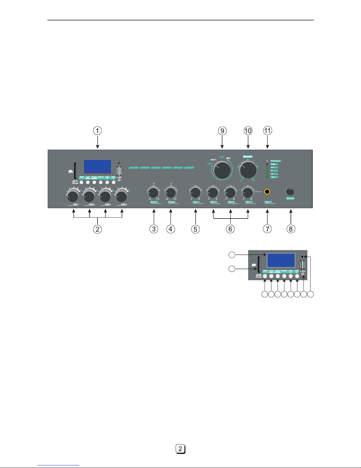
1. Mp3 Player
(1) The LCD window displays working message of Mp3.
(2) SD card socket.
(3) USB socket.
(4) The receive window of remote control.
(5) Mode: Push this key and release, change the playing source to FM
radio, USB or SD card; push it and hold it, turn on or turn off the player.
(6) Play/pause: In USB or SD playing mode, push this key and release,
change the player state into playing or pause.
(7) Folder/record: In USB or SD playing mode, push this key and release, enter the folder list; push this key and
hold it, enter the recording mode. In recording state, push this key and hold it, end recording and save it.
(8) Cyclical mode: In USB or SD playing mode, push this key and release, change cyclical mode to 1(one song),
A(all song cycle) or R(random play).
(9) PREV/VOL-: In USB or SD playing mode, push this key and release, jump to the previous song and play it;
push this key and hold it, decrease the playing volume.
(10) NEXT/VOL+: In USB or SD playing mode, push this key and release, jump to the next song and play it; push
this key and hold it, decrease the playing volume.
1
2
31098765 4
They are 4 rotatable band switches, to adjust 4 zone volumes in 6 steps.
2. Zone Knobs
3. Bass Control
A rotated knob to increase or lower the LOW of the input signal.
4. Treble Control
A rotated knob to increase or lower the HIGH of the input signal.
5. Line 1-3 Control
A rotated knob to adjust the level of the AUX input signal.
Page 5
REAL PANEL DESCRIPTION
12
6. Mic 1-3 Control
3 rotated knobs to adjust the level of the 3 MIC channel signals.
2060BC/2120BC/2240BC
7. Mic 1 Connector
To connect microphone with jack-plug, a priority microphone.
8. Power Switch
A button to turn on or off the power supply of the power amplifier.
10. Master Level Control
A rotated knob to adjust the level of the master output.
11. Power/Fault LED and 5-Segment Output Level LEDs
The Power/Fault two-colour LED shows green when power supply is on. It shows red when have a malfunction,
such as: load-short, zero-offset over or over-heat. The 5-segment level LED indicates input signal level.
9. Input Source Selector
A rotatable band switches with 4 steps to select an input source.
13 14
15 16 17 18
19
20
21
22
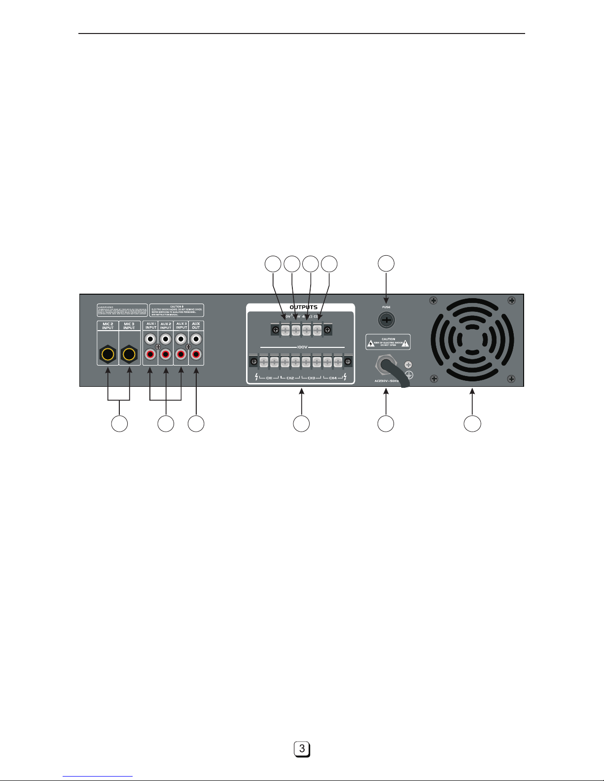
12. Mic 2&3 Input Sockets
Connect your microphones with 6.35mm jack-plug here. The voices are adjusted by Mic 2 and Mic 3 control control .
13. Aux 1-3 Input Sockets
Connect your LINE-sources here. The signals can be controlled via the controls LINE 1 to LINE 3.
14. Aux Out
Output socket for connecting further mixing amplifiers.
15. 100V Output Socket
This output socket with 100V voltage for connecting your PA-speakers .
17. 4-16Ω Output Socket
This output socket for connecting your passive speaker-system which has 4-16Ω impedance .
22. Air Export
18. Com Output Socket
Common pole for PA or passive connection.
20. Fuse Holder
Only replace the fuse when the device is disconnected from mains. Only use fuses of the same rating and Power.
21. Power Cable
The AC power input decided by client, the voltage may be AC230V~50Hz.
16. 70V Output Socket
This output socket with 70V voltage for connecting your PA-speakers .
19. Zone Output Socket
Eight screw terminals for 4 zone output connections.
Page 6
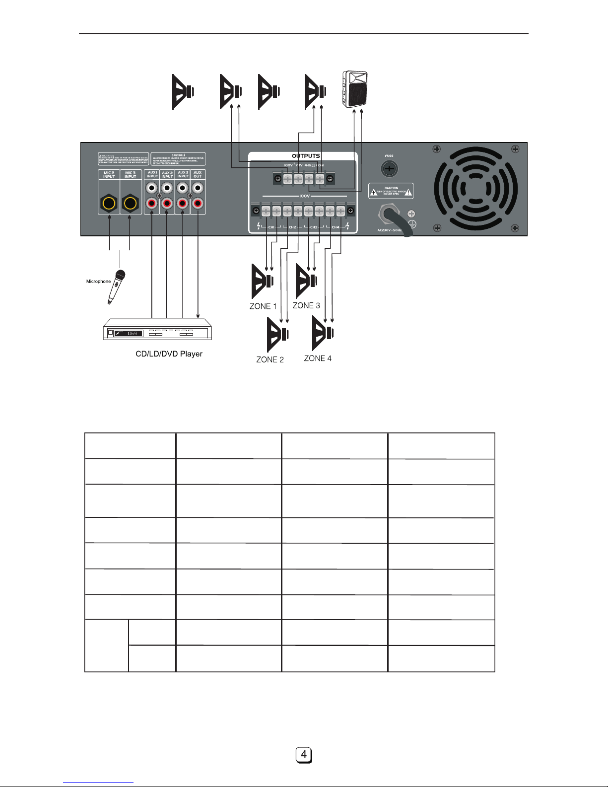
CONNECTORS
… …
70V
……
ON
OFF
100V
2060BC/2120BC/2240BC
TECHNICAL PARAMETER
Output power
Output type
Mic input
Line input
Frequency range
Distortion
Signal
/Noise
ratio:
Aux
Mic
MODEL
250 W RMS
70 V, 100 V
or 4-16Ω
3mV, 600 Ohms
80 Hz - 16 kHz
0.5 % (1 kHz) 0.5
85 dB
116 dB
2120BC2060BC 2240BC
120W RMS60W RMS
70 V, 100 V
or 4-16Ω
70 V, 100 V
or 4-16Ω
3mV, 600 Ohms
3mV, 600 Ohms
80 Hz - 16 kHz 80 Hz - 16 kHz
0.5 % (1 kHz)0.5 % (1 kHz)
85 dB85 dB
116 dB116 dB
200mV, 10k Ohms 200mV, 10k Ohms
200mV, 10k Ohms
 Loading...