

HQ TVS-HQ-FSB06B, TVS-HQ-FSB07B Installation Instructions Manual
Pitching angl e adj ust ment
3
5
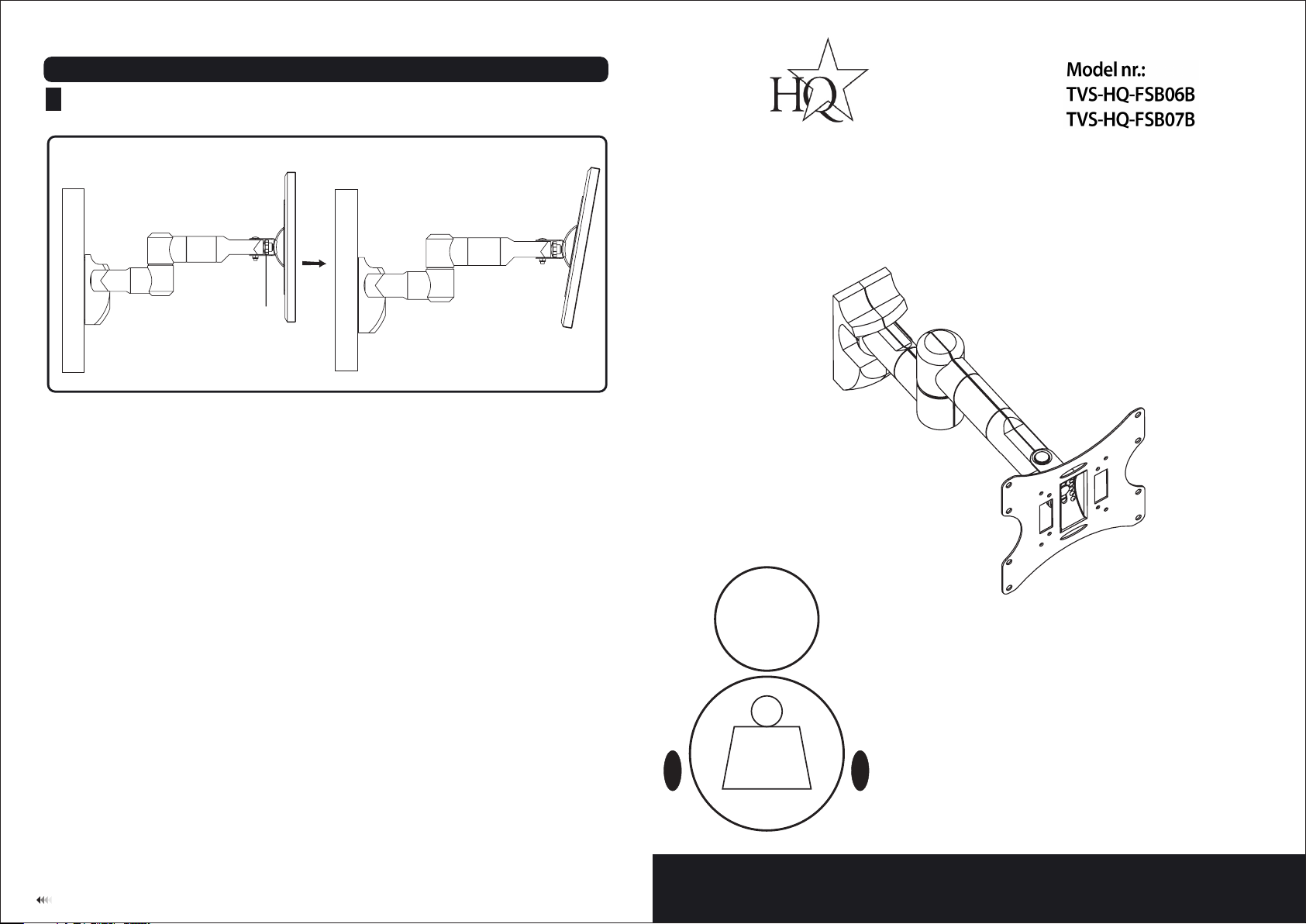
• Use t he ti lt ad justi ng kn ob to a dju st your TV t o the d esi red angle, t he pi tch ing angle ca n be ad jus ted
bet ween -20°~ 20° , as sh own in fig 5.1.
INSTALLATION INSTRUCTIONS
wal l
Tilt a djusti ng knob
Maintenan ce
Once you have mounted the bracket and the fl at scr een, check that th ey are suffi ciently secur e and safe to
use. You should check wheth er scr ews ar e fixe d well each two months. If yo u have any dou bts re garding the
installation, please consult our retailer or service depart ment for det ail.
wal l
fig. 5.1
Pitchin g an gle:
-20° ~ +20°
Swivel: 1 80°
30kg
(66lbs)
MAX
LCD Wall Mount
M
7
Max Loa d Cap acity : 30k g(6 6l bs)
NOTE: Read entire instructio n sh ee t be fo re y ou s ta rt i ns ta ll at io n an d as se mb ly.
WARNING
• Do not begin the installation of the product before you have read and understood the
instructions and warnings contained in this installation sheet. If you have any question
regarding any of the instruction or warning, please contact your local distributor.
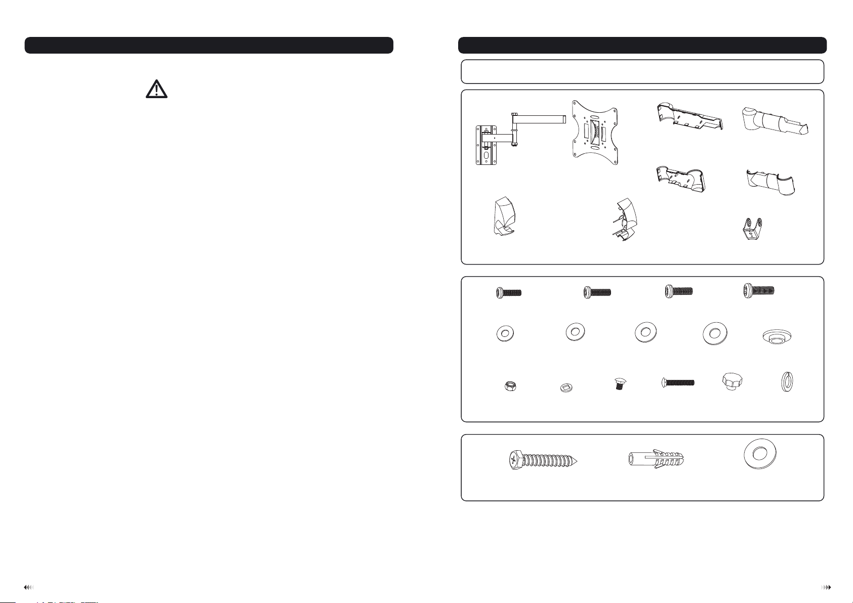
Component Checklist
IMPORTANT: Ens ure you h ave r eceiv ed al l parts a gai nst the c omp onent c hec klist p rio r to inst all in g. If a ny pa rt s
are m is sin g or fa ul ty, te lep hone th e spe cial fr anc hiser f or a re place men t.
decor at ive cov er 1C (x1)
decor at ive cov er 2 ( x1)
D
• Please refer to installation guide recommendation for required distance from wall to
avoid risk of property damage.
• This product should only be installed by someone of good mechanical aptitude, with
experience and basic building, and fully understands.
• Make sure that the supporting surface will safely support the combined load of the
equipment and all attached hardware and components.
• Never exceed the maximum load capacity.
• If mounting to wood wall studs, make sure that mounting screws are anchored into
the center of the studs. Use of an “edge to edge” stud finder is highly recommended.
• Always use an assistant or mechanical lifting equipment to safely lift and position
equipment.
• Tighten screws firmly, but do not over tighten. Over tightening can damage the items,
greatly reducing their holding power.
• This products intended for indoor use only. Using this product outdoors could lead to
product failure and personal injury.
wall pl at e(x1)
A
left de co rativ e co ver (x1 )
G
Package M
M4x10
(x4) M5x10 ( x4 )
M-A
D4 ( 4 .5x )
ø ø10
washe r (x 4)
M-E
M8 (x1)
M-J
Package W
adapt er b racke t (x 1)
D (ø .5 xø )
5 5 12
washe r (x 4)
M8 (x2)
M-K
B
right d ec orati ve c over (x 1)
M-B
M-F
H
D6 (ø6. 3x ø )
washe r (x 4)
M8x20 ( x1 )
M-L
decor at ive cov er 3E (x1)
M6x10 ( x4 )
M-C
16
M-G
D8 (ø8. 3x ø )
M8x50 ( x1 )
M-M
washe r
grip ho ld er (x1)
16
(x5)
M-H
M8 (x1)
M-N
decor at ive cov er 4 ( x1)
M8x15 ( x4 )
F
I
M-D
ø13.5 xø 5.5x3 .2 (x4)
M-I
washe r (x 1)
M-O
ST6.3 x5 5 (x6)
lag bol t
W-A
concr et e ancho r
W-B
(x6)
Tools required
Phillips Head Screw driver(200mm length exclude the handle)
·
M6 Socket and wrench
·
Electric drill and 10mm masonry bit for concrete wall installation
·
Marking Pen
·
Hammer
·
D (ø xø )
6 6.3 16
washe r (x 6)
W-C
21
 Loading...