

Page 1
recumbent
2016
technology
... recline in style!
Velotechnik
HP
hpvelotechnik.com
Operating manual
and service instructions
Feb. 2016
Page 2
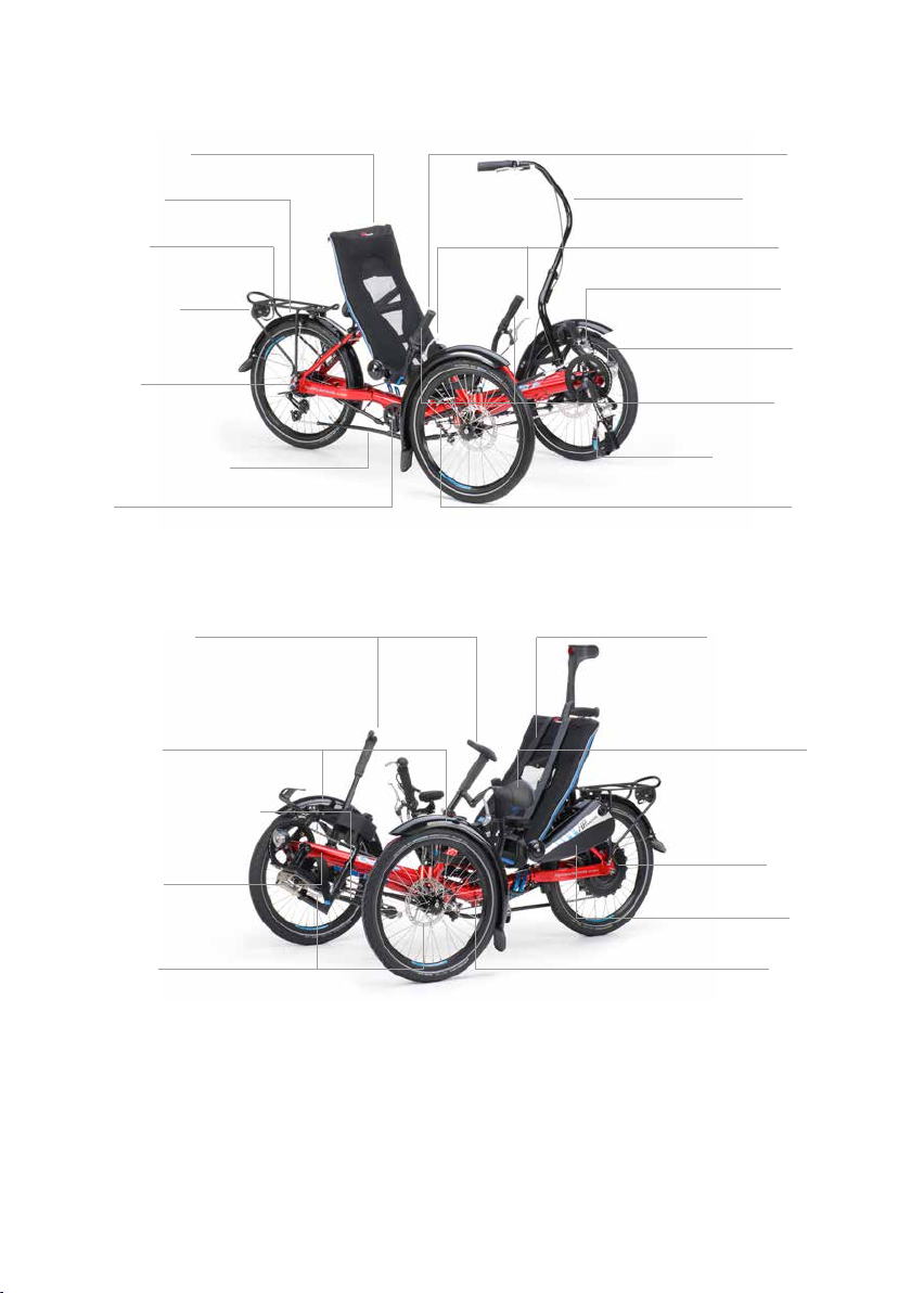
OrthoFlex-Seat
Handlebar
Trike fender
Rear rack
Rear light and
braking light*
Gearhub
Chain and chaintubes
Idler
Standing-up aid*
Trike fender
Front boom quick adjust*
Companion bar*
Brake lever
Cranks and
chainrings
Headlight
Twist shifter
Pedals with heelstrap
and foot clamp
Track rod
Retention belt system
Mirror*
Front boom
Brake discs
Scheme of the Gekko fxs and its components.
Parts marked with * are options.
Parts marked with ** belong to the optional electric assist system.
Hub motor**
Batterie**
Folding hinge
Page 3

Introduction
Dear customer,
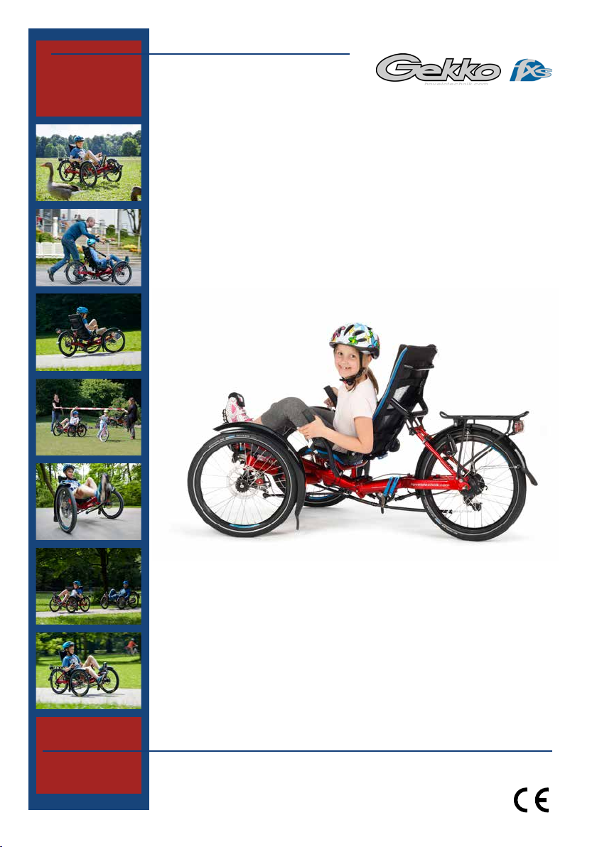
thank you for buying the recumbent bike Gekko fxs designed by HP
Velotechnik and congratulations on the purchase of your new recumbent tricycle!
With this high-quality tricycle, you will enjoy many years of exhilarating riding pleasure.
Your satisfaction and the safety of your child are our main concern.
On the following pages, this manual will inform you about important
safety issues as well as maintenance and care instructions.
Even if you have many years of experience with bicycles please do
take your time to read this manual carefully before the rst ride. Your
recumbent tricycle is designed with the latest recumbent technology
by HP
In this manual you will nd detailed instructions on how to optimize
your tricycle to meet your demands and riding style as well as your
size and weight. In addition to this, we have put together a collection
of information on care and maintenance as well as special technical
advice from our engineers. Important: Please send us the attached
warranty registration form for your extended warranty (see page 76).
Velotechnik that partly needs special treatment and care.
This guide helps you to keep your tricycle in perfect condition so you
will always experience maximum fun, comfort and safety.
Enjoy yourselves and have a great ride!
Paul J.W. Hollants, Dipl.-Ing. Daniel Pulvermüller and the
HP
Velotechnik team
Velotechnik
HP
1
Page 4

Content
Safety instructions 4
General safety instructions 4
Intended use 5
Indications 5
Contraindications 5
Individualisation 5
Load capacity 6
Carrying luggage 6
Final assembly 6
Bolts and nuts 7
Quick release levers 7
The rst miles 8
Safety instructions (bicycle) 9
Legal requirements 9
No alteration of parts 9
Frame number and identication marks 10
Added parts and accessories 10
Replacement of parts 10
Transport of children 11
Pedelec system 11
Trailer 11
Handling instructions 12
Riding a recumbent tricycle 12
Learning the new riding technique 12
How to ride correctly and safely 13
Wear protective clothing 13
Use special pedals 13
Slowly increase the strain 14
Adjusting your new tricycle 15
Basic adjustment of the frame length 15
The OrthoFlex mesh seat 17
Adjusting the seat mesh 18
Adjusting the seat back angle 18
Padding with seat cushion elements 18
Attaching the retention belt system 19
The head rest 21
Adjusting to your size 22
Adjusting the front boom 22
Adjusting the length with front boom quick
adjust 25
Special pedals 27
Heel support pedal 27
Ergonomic pedal / Ergonomic pedal with
lower leg xation 29
Clipless pedal 34
Adjusting the handlebars 36
A good setting for the handlebars 36
Setting the width and angle 36
Adjusting the cable length 38
Handlebar grips 38
Folding 39
Folding of Gekko fxs 39
Lighting system 43
Lighting systems for bicycles 43
Brakes 45
Handling of the brakes 45
One-hand operation for brakes 46
Maintenance of the brakes 47
Hydraulic brakes 48
HP
Velotechnik
2
Page 5

Content
Gear system and chain 50
Handling of the gear system 50
Adjusting the gear system 51
Chain 52
Chain tubes 54
Replacing the tubes 55
Chain roller 55
Go SwiSSDriVe pedelec system 56
Wheels 57
Disassembling the wheels 57
Tyres 57
Front wheels 58
Rear wheel 58
Spokes 58
Headset 59
Adjusting the headset 59
Wheel alignment 60
Measuring toe-setting 60
Adjusting toe setting 60
Mudguards 63
Front mudguards 63
Mounting of front mudguards 63
Rear rack 64
Rear rack 64
Water bottle cages 65
Water bottle cage 65
Comfort and ability options 66
Companion bar 66
Adjustment of the companion bar 66
Standing-up aid 67
Walking aid mount 67
Handling of the walking aid mount 67
Handrest 68
Maintenance and care 70
Maintenance routine 70
Wear and tear 70
Cleaning, conservation and disinfection 70
Storing the bicycle 72
Transport in the car 72
Technical Data 73
Technical Data 73
Tightening torques 74
Tightening torques 74
Warranty and Service 76
Warranty 76
Warranty policy 76
Warranty pass 77
Warranty pass 77
Service plan 85
Revision February 2016. For latest product
information and manuals, please check out
our website at www.hpvelotechnik.com.
hP Velotechnik ohG
Kapellenstraße 49
D-65830 Kriftel
Tel. +49 - 61 92 - 97 99 2-0
Fax +49 - 61 92 - 97 99 2-299
HP
Velotechnik
3
Page 6
General safety instructions
The manuals of component manufacturers
such as the brake manufacturer, the gear
system manufacturer, and the pedal manufacturer also belong to this manual. They give
detailed information on operating and
maintaining these specic parts. Please read
the manuals of the part manufacturers as
carefully as this manual.
Please share the information you have read
with your child and involve it in this process.
Make sure, that it has understood all relevant functions of safety. Please provide this
manual to any other user of your recumbent before using it. Attendants of mentally
handicapped persons have to make them
Safety instructions
understand all safety-related functions prior
to every ride; these drivers are only allowed
to use the Gekko fxs supervised by an adult.
The maintenance and adjustment of this
recumbent partly requires special tools and
skills. Do only works within your limits and,
for the purpose of your own safety, do not
go beyond. Should you be uncertain at any
point, get in contact with your local dealer.
The instructions in this manual apply only to
a completely assembled Gekko fxs tricycle
with standard parts from the series production of HP
The texts in the grey boxes are particularly
important for your safety. Please read them
carefully. The signs explained below will be
used in this document without beeing
explained again!
Danger! Texts that begin with
„Danger!“ mark an immediate danger for
your life and your health. Please read them
carefully.
Attention! Hints with the text
„Attention“ are important for your safety!
Velotechnik.
4
HP
Velotechnik
Page 7

General safety instructions
Intended use
Use your
the intended use.
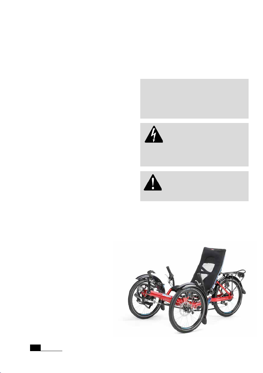
The Gekko fxs is a bike for the use on
streets and paved roads. This tricycle is not
designed for the use in racing and off-road
riding, for jumping or acrobatics, and you
must not ride across curbs, stairs, etc.
The Gekko fxs allows children and teenager
with specic handicaps (see indications) to
gain individual mobility. Physiotherapy gets
supported, to hold up and keep balance
is trained as well as the coordination of
movements.
The power transmission takes place in a
reclined position. Actuation occurs by a
rotation that the leg muscles transmit on
the pedal cranks. An optional electric motor
can give support.
Using your bike on public roads is only
allowed if it has been equipped with the accessories that are required by the applicable
trafc regulations of the country in which
you are using it.
Never drive without holding on! Before
your rst ride, read the chapter “Riding
a recumbent tricycle” on page 12 and
get carefully used to the different vehicle
performance.
Damage through inappropriate use, assembly errors, accidents or similar activities
and wilful damage results in the loss of any
warranty.
The intended use also includes the precise
observation of the prescribed usage and
maintenance regulations and instructions.
hP Velotechnik tricycle only for
Indications
According to your child‘s therapist suggestion, indications for riding this tricycle may be:
Neuromuscular disorders:
e. g. cerebral palsy or muscular dystrophy
The tricycle can also be used for rehabiltation of the mobility with coordination or
balance disorders and restricted natural
movement.
The tricycle should always be considered
when a child owing to its special physical
conditions is unable to ride standard children bicycles or vehicles, even with training
wheels.
Contraindications
The bike may not be used by persons
who are not able to ride a bike safely and
independent. For example in the case of
blindness or the unability to move necessary extremities controlled.
Individualisation
It is possible to adapte the Gekko fxs to
indivual demands. HP
huge variety of optional accessories. For
example: electric motor, one-hand operation, special pedals, head rest, standing-up aid,
handrest, walking aid mount and companion
ba r.
Velotechnik offers a
Safety instructions
HP
Velotechnik
5
Page 8
General safety instructions
Load capacity
The maximum load (rider + luggage) is
100 kg (220 lbs). The maximum total weight
(bicycle + rider + luggage) is 130 kg
(286 lbs). The lower limit is valid. With a
coupled trailer, the maximum total weight
must not exceed 130 kg (286 lbs).
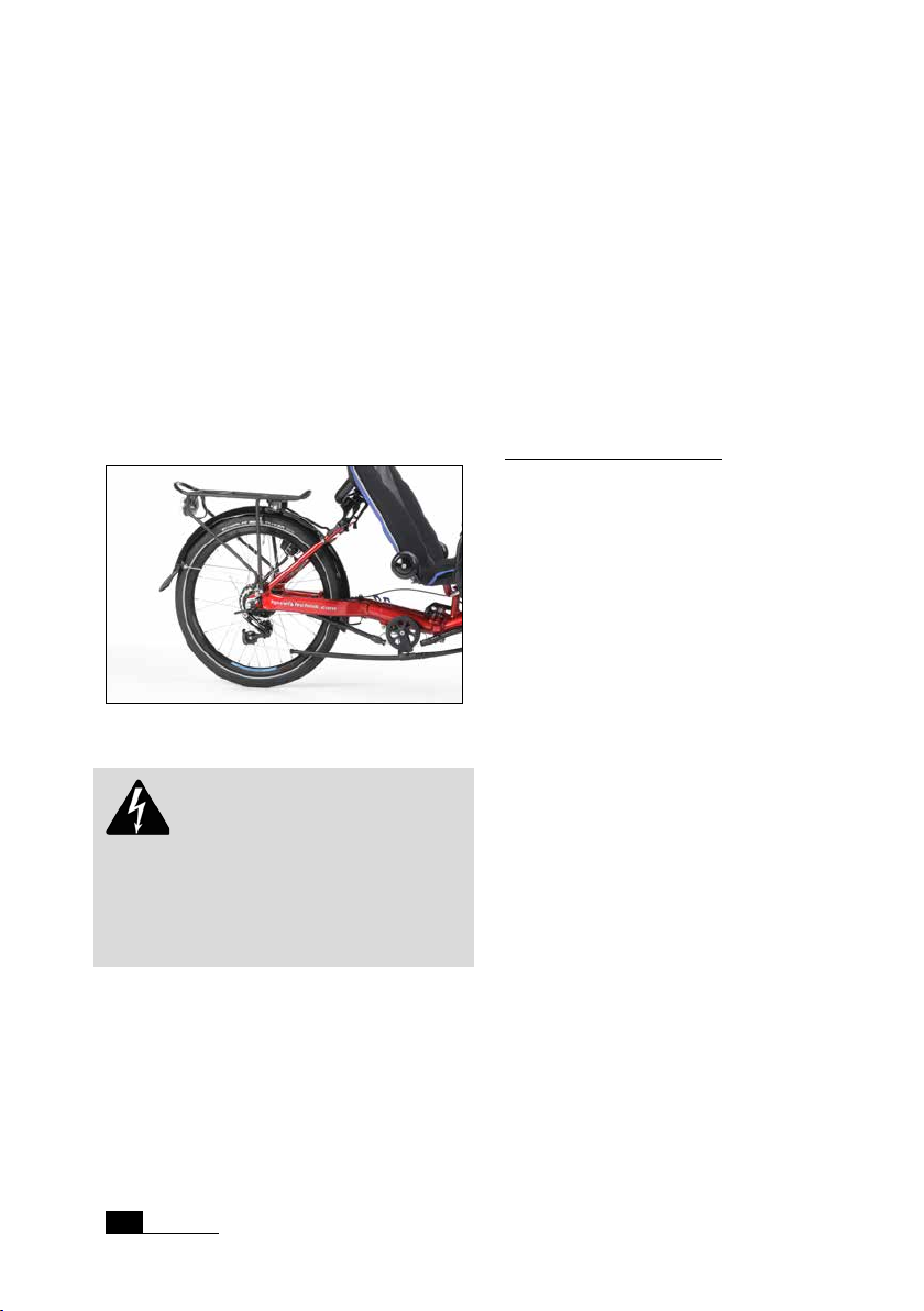
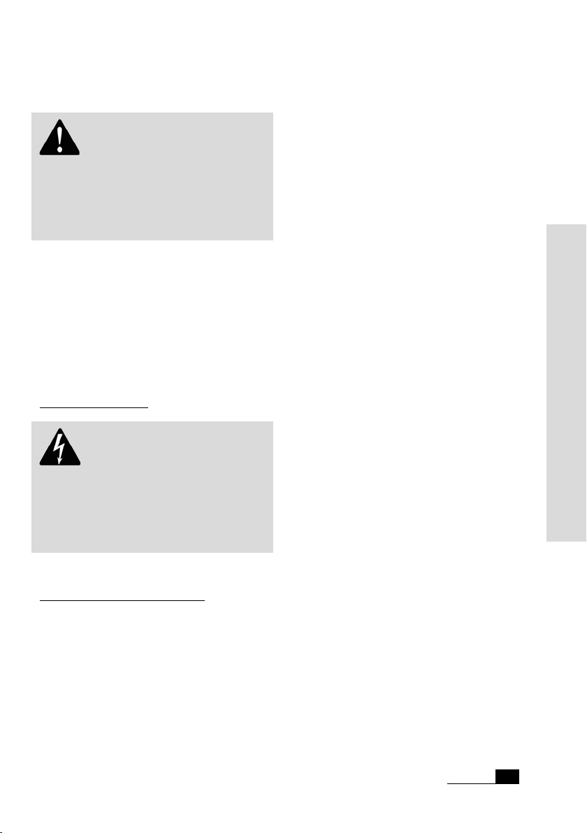
Carrying luggage
Luggage transport is only allowed with the
special racks designed by HP
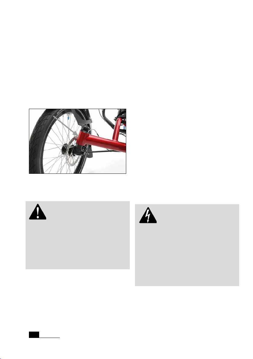
Rear rack on Gekko fxs
Danger! Additional loading can
inuence the handling of your tricycle considerably. If you plan on riding with heavy
luggage we advise you to make a test ride
on a street with no trafc to get used to
the new situation.
Velotechnik.
Take care that your luggage is safely stored
on the racks. Bags must be tightly fastened
to the racks so they can not move. Make
sure that loose parts like straps or belts can
not touch the wheels, the derailleur, or the
suspension.
The rear rack is designed for standard
tricycle panniers. Take care that your luggage
does not cover the lighting system and the
reectors of your tricycle and that they stay
fully functional.
Maximum load for carriers:
The maximum load on the rear rack is 25 kg
(55 lbs).
Final assembly
Your tricycle has been delivered to your
specialist dealer only partly assembled.
Your dealer has to have carefully nished
the assembly, perhaps altered the specica-
tion of your tricycle to meet your special
requirements and has to have performed
a test ride. Please make sure that this predelivery service is recorded in the Warranty
Pass at the end of this manual.
All screws must be checked and tightened,
especially on the handlebar, stem, knuckles,
swing arm pivot and wheels. Please follow
the tightening torque settings listed in the
table on page 74.
The load should be placed as close to the
body of the rider as possible, since this
results in better riding performance. You can
also improve the handling of the tricycle by
positioning the centre of gravity of the luggage as low as possible, so pack heavy items
in the bottom of your panniers.
HP
Velotechnik
6
Derailleurs and brakes must be checked and
adjusted. Please follow the instructions in
the manuals of the parts manufacturers that
come with this manual.
Page 9
General safety instructions
Bolts and nuts
Attention! Screws must be
tightened with prescribed tightening torque.
In this manual tightening torques are given
in „Nm“ (Newton meter). Always use a
torque wrench wherever a torque setting is
given in this manual. Never rely on „feeling“.
Screws tightened too much or not enough
can break, which can lead to dangerous
accidents. In case you don‘t own a torque
wrench have your bicycle mechanic do the
respective work. You will nd tables with
the prescribed torque settings on page 88
and 89 in this manual.
Screws gradually settle in and hence they
can come loose. Therefore check the screws
regularly if they are tightened appropriately
with a torque wrench.
In the tables on page 74 and 75 you will nd
the prescribed tightening torques, they refer
to greased screws!
The grease also prevents your screws from
seizing in their threads so that they won‘t
unscrew anymore. In particular, screws
made of stainless steel are susceptible to
this and therefore have always to be put in
with grease.
Do use high quality acid free grease, if possible a lubricant with added solid particles
like Teon or MoS2. Their ingredients still
work properly after the thinner grease has
been removed from the contact surfaces.
Alternatively you can use thread locker e.g.
loctite, that you apply to the screw before
you put it into the thread.
Always check the screws very diligently for
signs of corrosion. Rust at the screw heads
may also lead to the screw seizing in the
thread. When the metallic and shiny coating
of galvanised screws comes off and discloses
dull, gray-brown steel you have to exchange
the screw.
When you exchange screws please only use
screws of the same type. Screws come in
different strength classes. Please only use
galvanised screws of the same type and
strength, corresponding to the German
strength class 8.8 or stainless steel screws
grade A2-70, when not given any other
recommendation. If you are in doubt please
ask your specialist dealer.
Safety instructions
Quick release levers
Quick release levers hold wheels and seat in
position. A quick release lever consists of
two basic parts: the lever on one side provides the clamping force. With the adjusting
nut on the other side you adjust the clamping tension on the screw thread.
Danger! An incompletely or improperly closed quick release can result in
parts coming loose and hence in a crash,
possibly resulting in serious injury.
To open the quick release, move the lever
away from the frame. In doing so the
inscription „open“ should be visible on the
lever.
To close the quick release, move the lever
with power in the other direction so that
the word „close“ is visible on the outward
side of the lever.
HP
Velotechnik
7
Page 10

General safety instructions
At the start of the lever‘s motion, for, say,
half of its movement, the lever should move
very easily, without any clamping action. In
the second half of the lever‘s movement the
force on the leer should increase considerably, corresponding in the end to 15 – 20 kg
(33 – 40 lbs). In its nal position, the lever
should come parallel with the tricycle and
should not stick out to one side.
Check the security of the lever by attempting to twist the lever. If the lever can
be made to pivot around in a circle the
clamping is too loose. You must re-open the
quick release, hold the lever and increase
the clamping tension. Do this by screwing
the adjustment nut on the other side by
half a turn. Close the lever and check the
clamping anew.
Finally, check that the part being secured is
rmly xed: Lift each wheel several inches
off the ground and give it a slap onto the
tire from above. A properly xed wheel will
remain secure in the frame‘s dropouts. Parts
that are fastened with a quick release open
easily. Thus, they are more susceptible to
theft. Therefore, always secure the wheels
with a lock when you park your tricycle. It
is also possible to exchange the quick releases with special security screws (e.g. from
Pitlock) that can only be opened with a
special tool. For this please consult your
local specialist dealer.
The rst miles
The rst 300 km (186 miles) are important
for breaking in the tricycle. During the rst
use of a new tricycle the screws may settle
and become loose. Cables and spokes may
stretch. Bearings may show play. Please be
very attentive during that period.
After 300 km or after two months at the latest you will have to take your tricycle to a
bicycle mechanic for the rst service. Please
record this rst service and the works
performed in the warranty pass on page
77. This rst service is the prerequisite for
further use of the tricycle and for your
warranty claims.
Danger! Check the proper setting
of quick release levers always before riding,
especially when the bicycle has been unattended.
HP
Velotechnik
8
Page 11
Safety instructions (bicycle)
Legal requirements
When you ride your tricycle on public
roads it must comply with national legislation and guidelines. They will vary from
country to country.
In general, there are minimum standards for
brakes, reectors and lighting systems, as
well as usually a general duty to ensure that
your vehicle is in roadworthy safe condition.
There will also be a duty to ride in a safe
and responsible manner. If you ride your
HP
Velotechnik tricycle in trafc you should
be sure to observe all the applicable laws
and regulations.
In most countries, including Germany and
the UK, two independent braking systems
are required. Do not ride with only one
brake working! Please contact your local
dealer to nd out about your legal obligations.
In the scope of German StVZO your equipment has to meet the following requirements:
• two functional, independent brakes
• a dynamo or battery driven lighting sys-
tem with a white headlight aiming
forward whose beam center touches the
road 10 m ahead
• a red taillight and a red rear reector
which may be combined
• at least one white reector aiming for-
ward and a red large area reector with
“Z” label aiming to the back
• two yellow reectors attached to the
spokes in every wheel; may be substituted
by tires or rims with white reective ring
• yellow pedal reectors on both sides for
the pedals
• a bell
By default the Gekko fxs is equipped accordingly to the current valid StVZO.
As an addition, we recommend to mount a
ag on a pole for better visibility in trafc.
You can nd a bracket for the pole at the
rear rack or the rear light mount.
The safety equipment on your tricycle must
be checked before every ride and maintained in proper condition.
Trafc regulations may change. Please check
currently valid regulations or ask your
specialist dealer.
In Germany, children under the age of eight
only may use a bicycle on sidewalks and
under adult supervision. Take especially care
of pedestrians.
No alteration of parts
Attention! You are not allowed
to perform any work on the parts of the
tricycle, especially frame, fork, handlebar and
seat, which might endanger their solidity.
These works include drilling holes, welding,
brazing, paint methods that add heat or any
other chemical treatment. If any of these
works is done improperly it may result in a
loss of strength by direct damage or increased susceptibility to corrosion.
Safety instructions
HP
Velotechnik
9
Page 12
Safety instructions (bicycle)
Frame number and identication
marks
The frame number is placed on the one side
of the steering tube. If needed, an additional
identication number can be engraved at
the other side of the stering tube.
However, we recommend to use adhesive
stickers for additional identication numbers.
Position for identication mark on the Gekko fxs
Added parts and accessories
Attention! Mounting additional
parts or accessories is at your own risk. It
is important that you carefully read the
installation guide of the manufacturer. Additions to the handlebar like fairings, handle-
bar ttings, bottle holders, etc. may impair
your safety due to additional loading or clips
with sharp edges.
Additional accessories may impair the function of your recumbent tricycle. We advise
you to generally ask your dealer before you
mount any special parts or accessories to
your tricycle.
Take care that the handlebar and the wheels
always stay moveable. You must not add
any parts to the handlebar or the seat that
might endanger the rider through sharp
edged or pointed shapes while steering,
getting on and off the tricycle or bumping
against something.
Before you purchase a bell or a lighting
system make sure that these accessories
conform to your national laws and regulations.
Replacement of parts
The replacement of parts relevant for safety
(especially brakes, lighting system, stem,
handlebar, knuckle, drive train) may only be
done with original parts by a bicycle mechanic, since it requires a certain degree of skill,
suitable tools and mechanical aptitude.
Any technical change you perform on your
own is at your own risk! This can also result
in the loss of any warranty.
Danger! If any part is deformed
(e.g. due to an accident or overload), especially frame, knuckles, handlebar, seat
mountings, pedals, cranks and brakes, it is
not allowed to use it any further or repair
it. Do not try to straighten bent parts. You
must replace them for your own safety. If
you do not replace a damaged part it can
result in a total failure of the part and you
may be seriously injured!
10
HP
Velotechnik
Page 13

Safety instructions (bicycle)
Transport of children
Velotechnik tricycles are not designed
HP
for the transport of children. You are not
allowed to mount a child‘s seat.
It is only allowed to transport children in a
trailer that has been specially designed for
that purpose.
Pedelec system
Instructions for the use and safety of the
optional pedelec systems are referred in the
systems manufacturer‘s manuals. Please read
them carefully before use.
Trailer
You are allowed to use trailers (double trail
only) up to 40 kg (88 lbs).
When using a rear rack, you will need a
weber coupling.
Please make sure the maximum allowed
load on the trailer hitch is not exceeded.
weber offers a special, lowered coupling for
chariot trailers on 20 inch rear wheels.
Safety instructions
HP
Velotechnik
11
Page 14
Riding a recumbent tricycle
Learning the new riding technique
Your new tricycle has been assembled by
your dealer and adjusted together with
you as described on the pages 15 and
following in the chapter „Adjusting your
new tricycle“. Before you sit down on your
tricycle and enjoy your rst ride please
make yourself familiar with the instructions
on riding technique and handling.
To ride this recumbent you will have to
make yourself acquainted with the different
Handling instructions
riding position. Make sure that you and all
other future users of this tricycle will have
read this manual carefully prior to the rst
ride. If you are in doubt please consult your
local dealer.
Before the rst ride the users of this
recumbent have to practice and make themselves familiar with the different handling.
We recommend to practice on a quiet road
away from trafc. Before you ride the tricycle in trafc you must master the handling
completely.
Danger! Never touch the ground
with your feet while the tricycle is still
moving. The feet could be caught on the
ground and be pulled backwards and
dragged under the cross bar which could
lead to a serious injury. We strongly recommend using a pedal binding system like
clipless pedals or toe clips and straps.
Keep all three wheels on the ground while
riding. If you are cornering too fast, your
tricycle can be upset and fall over. Lean into
curves when turning sharply. At high speed,
keep your upper body quiet as any upper
body movements can inuence the steering
of the tricycle.
Practice cornering away from trafc to learn
what speed is safe at a specic turning angle.
If you lift up a front wheel, immediately
steer in the opposite direction to bring it
safely back to the ground.
Attention! When getting on and
off the tricycle, make sure to avoid pulling
at the handle bars or stepping on the tie
rods. To get off the tricycle, sit upright on
the front seat edge and then stand up. Grip
the front wheels or the seat back as extra
support, not the handlebars. If you pull
rmly at the handlebars, the steering can
be damaged.
HP
Velotechnik
12
Danger! Please be aware that due
to your low seat height other road users
may notice you very late. Ride anticipatory
with this in mind.
This is especially important while riding in
darkness. You yourself have a much better
view than others perceive you. Ride defensively. We recommend mounting a well visible
and reecting ag to the tricycle while using
it in trafc. Find more information about
lighting systems on page 43. Please ask your
dealer for more information.
Page 15
Riding a recumbent tricycle
How to ride correctly and safely
Attention! Always carry your
tricycle over stairs and curb stones. Do
not ride through big road holes. Especially
when road holes are lled with water it is
very difcult to guess how deep they really
are.
In case you hit such an obstacle, frame and
steering may be damaged which can result
in a serious fall. At rst, the damage may
be unnoticed. Please check your tricycle
immediately for deformations and cracks. If
you are in doubt please consult your local
dealer.
Do not ride freehand
Danger! In order to ride safely
you have to keep both hands at the handlebar. Even when signalling keep at least one
hand at the handlebar. Otherwise, unforeseen bumps in the road or oscillations of
the steering may lead to a serious fall.
How to ride correctly and safely
Always adjust your speed to the trafc, the
road and the weather conditions. Ride slowly in curves and on unknown roads. Always
ride at a safe distance from other road
users, and when you ride in a group never
ride side by side.
most attentive car driver may not see you
due to your low riding position.
Wear protective clothing
Riding a tricycle is a potentially dangerous
sport where accidents can happen even
when you take care of every safety instruction prescribed.
We recommend you to wear an approved
bicycle helmet that ts well. Protect yourself
by wearing special sports clothing that ts
tight and is reective. If you‘re wearing
wide pants use clips to protect them from
getting caught in the chain – or use an old
fashioned method and put the pants in your
sockets.
When you fall with a recumbent you’ll usually land on the side of your hips and your
hands. Wearing reinforced cycling shorts and
gloves reduces the danger of skin injuries
considerably.
Use special pedals
The Gekko fxs comes with heel support
pedals by default.
If you wish, you can equip your recumbent
tricycle with clippless pedals, ergonomic
safety pedals or ergonomic pedals with
lower leg xation. To accomodate persons
with different physical impairments, the ergonomic versions can optional be choosed
for one side or both side.
Find more information on pages 27 and
following.
Handling instructions
When you approach a trafc light never ride
past the line of waiting cars since even the
HP
Velotechnik
13
Page 16

Riding a recumbent tricycle
Slowly increase the strain
We recommend you to perform only short
rides without much power during the rst
weeks. Always use a low gear and ride with
a high pedalling frequency. Only after having
acquired some training do increase the
strain slowly.
When you ride on a recumbent you use
different muscles than on a conventional
bicycle, and they have to be trained rst. The
very high position of the bottom bracket
requires your muscles and blood transport
system to slowly familiarise with the new
position. In case of an overload the blood
circulation in your legs may be affected
which shows in loss of power, a prickling in
the toes, falling asleep of the legs or cramps.
When you feature a sporty way of riding it
can take up to 6 months until you have become accustomed to your new recumbent.
If there is pain in your knees occuring while
riding this is usually the result of too much
power put into pedalling. The good support
of the back sometimes misleads to putting
the full power of the legs in the pedal, simi-
lar to the leg training machines in a tness
center. When you repeat it regularly it is
harmful for the knees. Pain in the knees often results from an overuse of the muscles
in the knee that can also be strengthened by
exercise.
Please contact your physician if you have
pain over a longer period of time.
Also, a wrong adjustment of the front boom
to the leg length (in most cases too short)
can lead to pain in the knees. Advices for
increasing the training can be found in a lot
of cycling books or magazines. Your pedalling frequency should stay between 80 – 100
revolutions per minute and not fall below
60 while going uphill. If necessary consult
your local dealer and have him adapt the
gear range to your style of riding.
HP
Velotechnik
14
Page 17
Adjusting your new tricycle
Your position on the recumbent bicycle is
essential for your riding comfort, well-being
and efcient cycling. Therefore you should
adjust the frame, seat, handlebar and suspension to your individual requirements.
Find detailed information about the possibilities of adjustment on the following pages.
Danger! All procedures described
here require a certain degree of skill, suitable tools and mechanical aptitude. After
any adjustment perform a static check and
take a test ride on a quiet street, away from
trafc. If you have any doubts please contact
your local dealer.
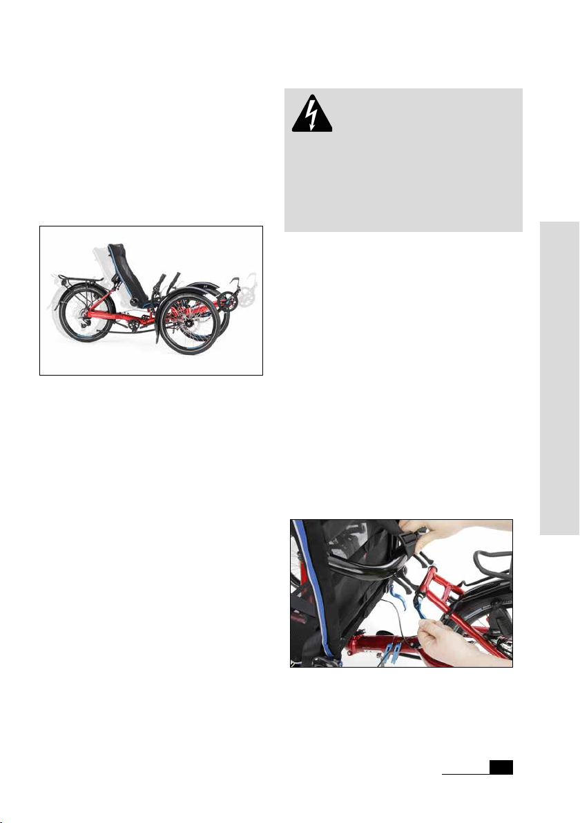
Basic adjustment of the frame length
For the basic adjustment of the frame length
for different body heights, the rear frame
tube and the seating have to be adjusted
with the blue quick release levers.
Adjusting range of the Gekko fxs
If your tricycle is equipped with the optional
front boom quick adjust, please read the instructions in the separate manual in addition
to the following instructions.
The Gekko fxs can be adapted for riders
between 1,20 m to 1,80 m (3'11" to 5'11").
The basic adjustment takes place by changing the frame length.
In order to adapt the bicycle as closely as
possible to your body dimensions and to
nd your ideal position you need to adjust
the front boom, seat and handlebars.
If you open these quick release levers of the
OrthoFlex-seat, seat depth and frame length
can interdependent be slided in or pulled
out.
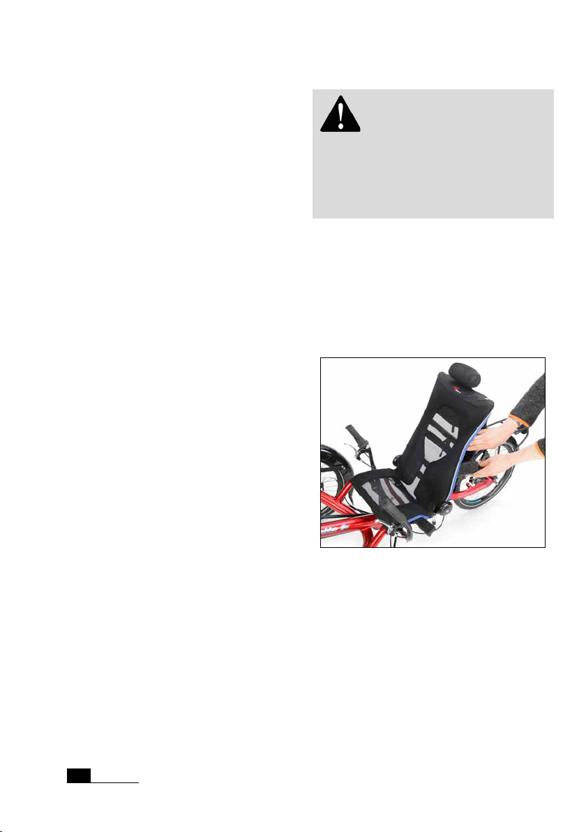
First, open the seatback quick release lever
that allows to adjust the seat angle. Then,
swivel the seatback to the front.
Opening the seat back quick release lever
Velotechnik
HP
15
Handling instructions
Page 18
Adjusting your new tricycle
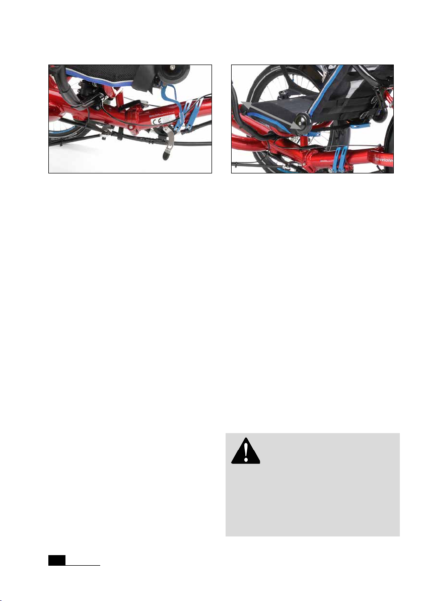
1
2
Rear frame with frame quick release levers (1) and
seat quick release levers (2)
Now open the frame quick release lever
(on the left side, in front of the rear wheel).
Then, you can slide the rear frame part in
or pull it out to the required lenght.
Make sure, that the end of the frame tube
is not visible in the clamping slot when you
look from below. In the case it is visible,
slide the rear frame part back in until the
tube end is not visible anymore.
If the desired length is reached, align the
rear frame part to a neutral position. Then,
close the quick release lever only half.
Open the two seat quick release levers at
the rear edges of the seating. If necessary,
knock a little on the quick release levers in
order to loosen the wedge inside the seat
tube.
Then, you can slide the seating length in or
pull it out. If the movement is not working
or wedged, you can help with small knocks
on the lower part of the seatback.
Make sure, that the seat net in the front
part slides along as well.
The seating length can be slided in or pulled out.
Next, slide the seating so far in that you can
insert the seat mountings easily back into
the mounting of the seatback quick release
levers.
Check if the seat back is perpendicular to
the riding direction if you look from above.
Correct if not.
Then close the seating quick release levers
and the frame quick release levers completely.
Finally, adjust the desired seat back angle
(see page 18) and close the seat quick
release lever.
You can use the optional adjustable end
stops, that allow an exact positioning of the
seat.
Attention! The minimum insertion
depth of the rear frame part into the main
frame is 6,5 cm (2 1/2"). The end of the
rear frame part must not be visible in the
clamping slot when you look at the main
frame from below, since this may result in a
damage of the frame.
16
HP
Velotechnik
Page 19
Adjusting your new tricycle
The OrthoFlex base length can be be inni-
Attention! Always tightly close
the seatback quick release lever, the seating
quick release levers and the frame quick release levers. The seat is a structural part of
the tricycle frame. An opened quick release
may lead to frame damage. Please pay attention to the instructions about quick release
levers on page 7.
The OrthoFlex mesh seat
The Gekko fxs comes with the OrthoFlex mesh seat. The seat is integrated into
the frame and remains on the tricycle for
folding. The seat cushion and the characteristic of the seat net material the OrthoFlex
mesh seat is slightly cushioned.
The seat mesh is washable and has lateral
reective strips to improve visibility at dusk.
In the top of the backrest is a practical
pouch where you can put small items like
keys, wallet as well as an optional rain protection cover for the seat.
tely adjusted together with the rear frame
to the riders size (see page 15). With a
quick release, the seat angle can be adjusted
between 48 and 64 degrees.
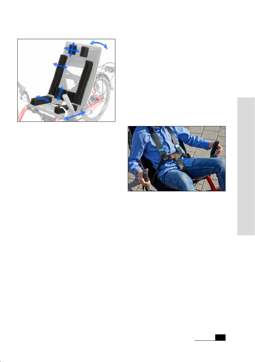
The contour of the seat can be adapted
to the natural S-shape of the spine. The
support of the pedaling forces takes place in
the area of the lumbar vertebrae. By arranging the eight individually adjustable padding
elements in the seat pockets adjustments in
the lordotic area (lower lumbar spine) are
possible.
The OrthoFlex-seat is also a practical base
platform for therapeutic changes by an
orthopaedic technician who can install
custom seat support pads in the pockets.
The adjustment of the seat mesh and the
proper seat angle is crucial for a comfortable feeling while riding your recumbent.
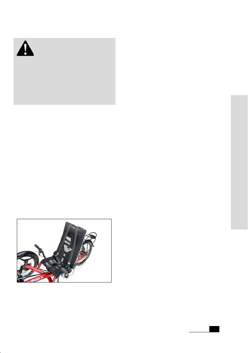
The Gekko fxs has a retention belt system
with customizable straps on the seat. The
adjustable retention belt system can be
used, depending on the therapeutic need, as
lap belt or as 4- or 5-point-belt.
Handling instructions
OrthoFlex mesh seat with retention belt system
The seat can be individually adjusted to
different therapeutic needs.
Riders above 1,40 m (4'7") can install an
optional head-rest, adjustable in height and
angle.
At the left top edge of the seatback is an
adapter for a ag post.
Velotechnik
HP
17
Page 20
Adjusting your new tricycle
Adjusting the seat mesh
Eight tension belts on the back side of the
seat allow the adjustment oft the seat net
to your needs.
Does the seat feel to soft or gives you the
feeling of sitting on the seat frame, increase
the tension of the belts on the back side of
the seat.
Attention! Always tightly close
the seatback quick release lever. The seat is
a structural part of the tricycle frame. An
opened quick release may lead to frame
damage. Please pay attention to the instruc-
tions about quick release levers on page 7.
Is it hard or uncomfortable, or do you feel
like slipping off when going through curves,
release the belts in the relating area.
It may be necessary to put a high force on
the belts to apply sufcient tension to the
belts. If it can not be done by hand, make
use of a at nose pliers and pull the lose
end of the belts rmly. To easily loosen the
belt, pull up the round end of the strap
retainer.
Adjusting the seat back angle
A great advantage of the OrthoFlex mesh
seat on your Gekko fxs is the possibility
to adjust the seat back angle very quickly.
Thus rides in an upright seat position or in
a at position are possible according to the
individual needs.
The seat back is fastened with a quick
release lever on a slotted aluminium seat
mounting. You can adjust the seat back angle
by 16 degrees by simply opening the quick
release lever. Having set up your desired
seat back angle close the quick release tightly to make sure the seat back will not move
during the ride.
Padding with seat cushion elements
The sides of the seat are equipped with
special pockets – their openings are clearly
marked by blue ribbons. Open the hookand-loop straps of the mesh seat there.
The pockets for the padding are closed with hook-andloop straps.
Now, you can arrange the eight individually
adjustable padding elements in the pockets
according to the rider‘s needs.
You can slightly reduce the tension of the
seat seat net to get more play for inserting
the padding elements.
18
HP
Velotechnik
Page 21
Adjusting your new tricycle
the OrthoFlex seat.
1
The entire seat mesh can be detached from
the seat frame and be washed at 30° C with
the tension belts.
3
Attaching the retention belt system
2
4
The OrthoFlex seat with adjustable padding cushions.
Following areas may be padded:
Head
The padding cushions No. 1 may be adjusted
in distance and height in order to support
the head in an ideal position and give some
orientation.
Lordotic area (lower lumbar spine)
The padding cushions No. 2 may be adjusted
in width and height to form a lumbar
support.
Sides
The padding cushions No. 3 and 4 may be
adjusted in width to give lateral support and
orientation.
Every padding cushion can be individually
cut with a knife. Replacements of padding
cushions may be reordered. When not
needed, the seat can also be used without
padding cushions.
The retention belt system on the Gekko
fxs consists of a lap belt, a harness belt and
a crotch belt. These can be combined as a
single 2-point belt and a 4- or 5-point belt.
5-point retention belt
Depending on the required retaining function, straps may be removed or re-attached
to the seat. The belts can be adapted to the
body proportions.
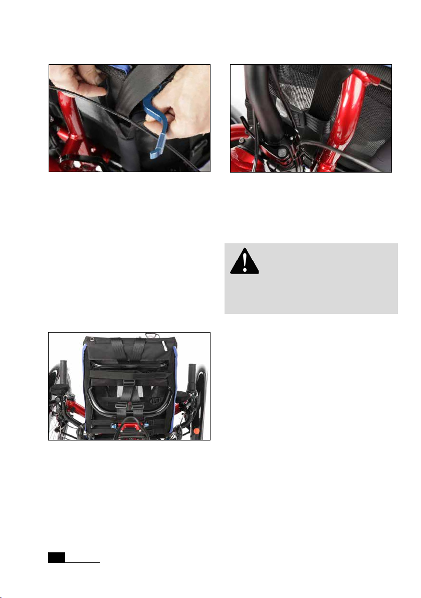
For attaching the belts to the tricycle, the
tension straps and the seat frame are used.
First attach the lap belt with the two supplied neoprene hook-and-loop sleeves to
the rear seating tension belt.
Handling instructions
After adjusting the padding cushions, close
the sides and press the hook-and-loop
straps tightly together.
Proceed as described above, if you want to
use custom-made orthopedic moldings in
HP
Velotechnik
19
Page 22
Adjusting your new tricycle
Attaching the lap belt
Then the harness belt is looped on the thick
seat frame cross tube between the seat
mountings. The straps then go underneath
the upper seatback tension belt and the
thin seat frame cross tube. The harness belt
parts are connected with a slidable buckle.
With this, the desired width of the harness
belt can be adjusted at the neck. The left
and right side of the lap belt get put through
the loops at the ends of the harness belt.
Positioning of the harness belt
Position of the crotch belt
Open or close the lap belt with the red
press button of the lap belt buckle.
Attention! Loose belt parts can be
caught in the wheel and cause an accident.
Make sure that the belt is always closed and
no loose belt ends are hanging off the bike.
The crotch belt has to be looped around
the middle seating tension belt. It is adjustable in length with a buckle. Before closing
the belt, put the lap belt through the loop
at the end.
HP
Velotechnik
20
Page 23
Adjusting your new tricycle
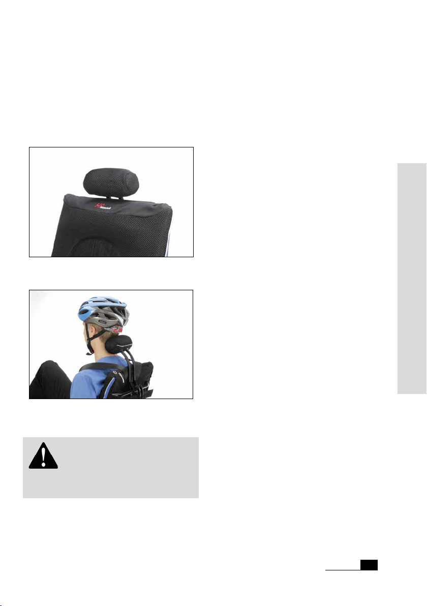
The head rest
OrthoFlex-seats can be equipped with
a head / neck rest which is adjustable in
height and angle. Mounting and adjustment
is possible with two quick-release levers on
the seat frame.
Head rest on the OrthoFlex-seat
Position of the head rest in the neck when using a
helmet.
Attention! Do not push or carry
your tricycle on the head rest, this may
damage the head rest or the seat!
HP
Velotechnik
Handling instructions
21
Page 24
Adjusting to your size
Adjusting the front boom
In order to adjust the leg length you have to
move the front boom (the front part of the
frame where the cranks are mounted) in
the main frame.
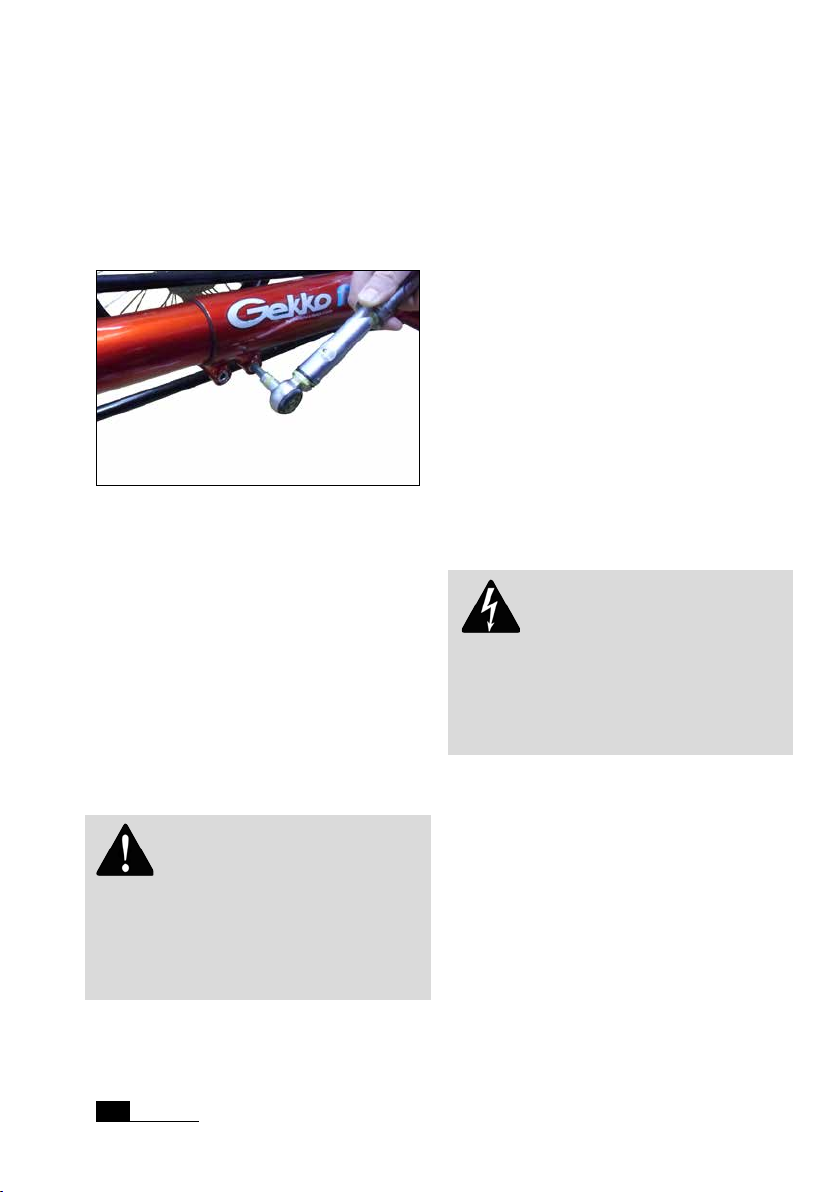
Loosing the bolts to adjust the front boom
Unscrew the bolts M8 x 35 under the main
tube with a 6 mm Allen key. Take a grip on
the front derailleur tube or both cranks and
move the front boom further into the frame
or pull it out while cautiously turning it.
Before you pull out the front boom shift the
chain to the smallest chain ring and sprocket. Turn the cranks a little bit backwards
while pulling. Thus the chain is not under
tension.
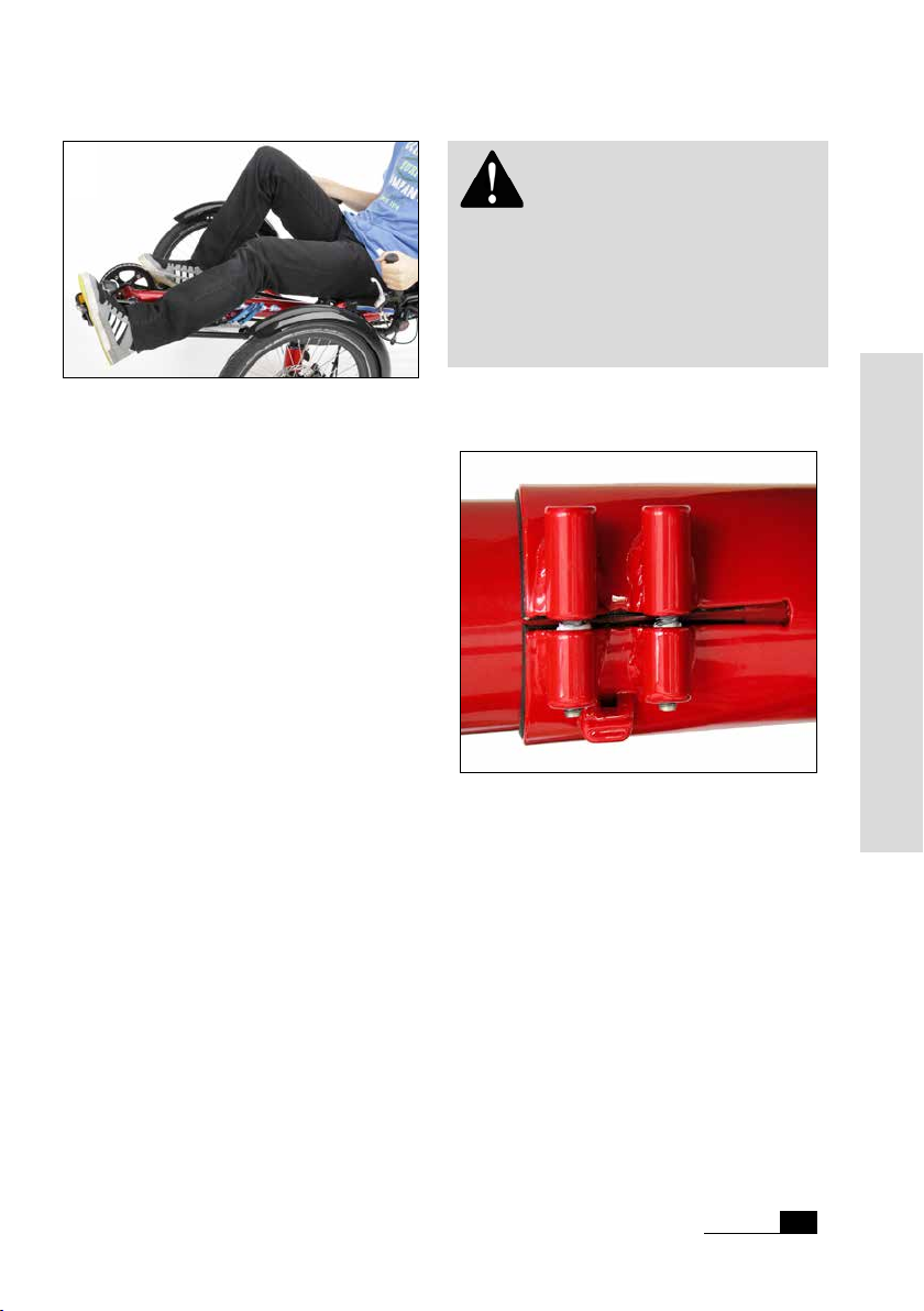
Adjust the front boom in a way that your
leg is fully extended when your heel (wea-
ring at shoes) is in the foremost position
on the pedal. Experience shows that the
pedal-to-seat distance on a recumbent can
be slightly longer than on a conventional
bicycle.
While you are pedalling, the ball of your
foot should be positioned above the centre
of the pedal axle.
It is important that your leg is not fully
straightened when the crank is in the foremost position. If the distance is too long it is
difcult to overcome this dead point, pedalling becomes uncomfortable and there is
too much strain on the sinews of your feet
and legs. If the distance is too short you may
suffer from knee pain.
Danger! When you insert the
front boom, the front boom and the inner
wall of the tube must be totally free from
grease, otherwise it will not clamp properly
and may turn while you are riding. This can
result in serious accidents.
Attention! After you have unscrewed the clamping bolts take them off and
examine them for deformation. Lubricate
threads and heads thoroughly. Then re-t
the bolts. If they don‘t turn easily you will
have to replace the bolts.
HP
Velotechnik
22
Page 25
Adjusting to your size
Adjust the front boom so that your knee will not be fully
straightened when paddling.
For riders with short leg length the front
boom has to be cut by a bicycle mechanic,
so it can be inserted maximum possible. It
is important to trim the end of the tube
neatly. The bare metal of the shortened tube
end has to be protected against corrosion
with a paint stick or wax spray.
The maximum insertion of the front boom
is limited by possible heel cycle of the
frame’s cross bar, depending on the rider’s
shoe size. Please check before riding your
tricycle that there is enough heel clearance
(depending on insertion depth of the front
boom and your shoe size). If you colide, you
have to choose a shorter crank. There are
cranks in following lengths: 115 mm, 135 mm
and 155 mm.
Look beyond the bottom bracket shell
at the rear wheel axle and align the front
boom parallel to it. Then sit down on your
tricycle and check the position.
Attention! The minimum insertion
depth of the front boom into the main
frame is 8 cm (3 1/5"). The end of the front
boom must not be visible in the clamping
slot when you look at the main frame from
below, since this may result in a damage of
the frame.
The rear end of the front boon must never be visible in
the clamping slot.
Tighten the bolts with a torque wrench
(tightening torque 14 – 16 Nm). On your
rst ride check whether there is sufcient
clamping. There might be the danger otherwise, that a single bolt overloads and the
frame gets damaged.
Handling instructions
HP
Velotechnik
23
Page 26
Adjusting to your size
Danger! If the bolts are tightened
too much or bent, the screw or the frame
can break! If the clamping is insufcient the
front boom can turn during a ride which
may cause your feet to slip from the pedals
and lead to injuries.
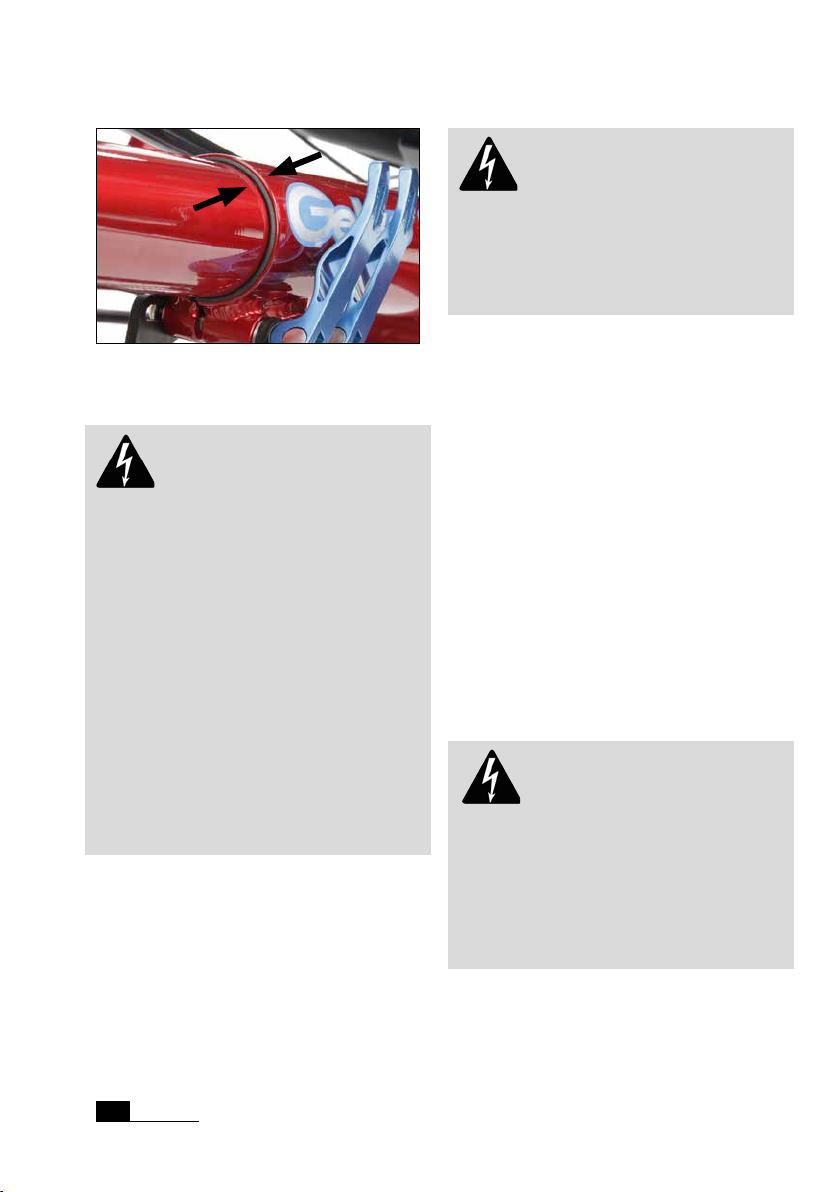
The plastic bush between front boom and main frame
must be visible at all time.
Danger! There must be a bushing
(a slotted tube of plastic with edges to the
front and the clamping slot) in the main
frame’s front boom hole that is glued in the
frame. This bush ensures safe clamping of
the front boom and protects the paint. It is
important to take care that this bush is
always visible at the front end of the main
frame. The lower slot has to be aligned in
coincidence with the slot in the main frame.
If this bush is missing or moved to the back
of the tube while inserting the front boom,
safe clamping is no longer guaranteed, even
if it seems to be the case at rst glance. If
the front boom is not clamped properly
it may turn and lead to a fall. A missing or
misaligned bush will lead to frame damage.
After moving the bottom bracket tube your
dealer has to adjust the chain length. By default your recumbent tricycle comes with a
very long chain so the adjustment range of
the tricycle can be fully used without the
need to lengthen the chain.
After the basic adjustment of the leg length
done by your dealer before handing over
the tricycle, the chain has to be shortened so that the derailleur cage is not fully
turned forward while shifting on the largest
chain ring in front and the smallest sprocket
behind. In order to choose the right chain
length, please consult the manual of the
derailleur manufacturer.
Danger! After the chain has been
shortened it must be closed with a special
closing link or a chain riveting tool that expands the rivet while riveting (i.e.
Revolver). A poorly joined chain may break
and thus lead to damage or injury. Chain
length adjustments or chain changes should
be done by your bicycle mechanic.
rohloff-
24
HP
Velotechnik
Page 27
Adjusting to your size
We recommend to slightly readjusting the
front boom every 3 months in order to
provide a slightly different position to your
muscles and ankles. You might also nd a
more comfortable and more efcient riding
position.
A wrong adjustment may lead to pain in
your knees and inefcient pedalling. In
addition we recommend riding with a high
pedalling cadence, which means to pedal fast
and with little pressure. Pedalling with too
much pressure may also lead to pain in the
knees. You will nd more information about
this in the chapter „Slowly increase the
strain“ on page 14.
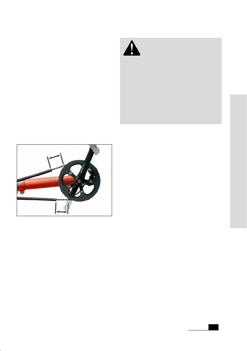
Check that there is at least a 5 cm (2") clearance between the end of the chain tube and other parts of the
drive train.
Attention! Take care that the
chain tubes have a clearance of at least 5 cm
(2") to the rear derailleur and the front
derailleur even under maximum tension of
the chain and make sure that the tubes are
held tight in their fastenings. The front upper
tube can be moved to the rear for length
adjustment. Shorten the tubes if necessary. If
the end of the chain tube gets in touch with
the rotating chain rings it can be locked-up
and destroyed.
Adjusting the length with front boom
quick adjust
The front boom quick adjust is additional
equipment for HP
that feature a telescopic front boom for leg
length adjustment. It replaces the standard
bolts of the front boom clamping by quick
release levers. Two pulleys provide chain
length compensation while moving the front
boom.
The front boom must be clean and free
from wax or tenacious remains of chain
lube to make sure it can be easily slid in and
out.
Velotechnik recumbents
Handling instructions
The chain tubes must be prevented from
moving by a rubber tube over the retention
spring.
After adjusting the front boom, the gap in
the clamping slot between the front boom
and the main frame should be sealed with
wax or silicone in order to protect your
frame from the penetration of water and
dirt and hence damage through corrosion
which may lead to a broken frame.
First, shift the chain to the largest chain ring
and the largest sprocket to check the correct chain length.
Open both quick release levers. Slide the
front boom into the frame or pull it out until you’ve reached the required frame length.
Velotechnik
HP
25
Page 28

Adjusting to your size
Routing of the chain over the idlers of the front boom
quick adjust
To slide the front boom in, grip the cranks
and turn them against the tensioned chain.
The force on the chain helps to move the
front boom into the frame tube.
To pull the front boom out, grip the derailleur tube if available. If you pull at the
cranks, you’ll have to turn them backwards
at the same time, else the tensioned chain
will balk the motion.
adjust the whole adjusting range of the front
boom with the front boom quick adjust.
Moving the front boom is easier when
turning it a little bit from side to side. When
doing this, make sure the pulley bracket
doesn’t scratch the frame and its lug won’t
be bent. That’s why we recommend to only
turn the front boom clockwise (and back
afterwards) when looking from the front.
Align the bottom bracket axis horizontally
when looking from the front. Close both
quick release levers. Please pay attention to
the instructions about quick release levers
on page 7.
Move the chain to the smallest chain ring
and the smallest sprocket. Check the chain
length. The rear derailleur cage should not
be completely swivelled to the back to still
apply tension to the chain. It is possible to
HP
Velotechnik
26
Page 29

Special pedals
Heel support pedal
4
2
5
1
Heel support sheet (1), heel support strap tube (2),
heel support hook (3), pedal toe clip (4), pedal (5)
and heep support strap (6)
The Gekko fxs comes with the
technik heel support pedals by default. This
is a comfortable alternative to clipless pedal
systems.
It offers a safe foothold while riding recumbent tricycles without wearing special
cycling shoes.
Mounting the pedal on your tricycle
The heel support pedal comes completely
assembled and ready to mount on your
tricycle.
Depending on the mounting side, the thread
is a left hand thread (left side) or a right
hand thread (right side). If there are already
pedals on the bike, demount them rst.
Use a little bit of tting grease on the
thread of the pedal. Screw the pedal into
the crank and use a 15 mm open end
wrench or 6 mm Allen wrench to tighten it.
6
3
hP Velo-
Adjustment
The pedal is suitable for shoe lengths
from 22 to 28 cm (8.5 – 11 inches). If you
need larger pedals, there is a version for
shoe lengths from 27 to 35 cm (10.5 – 13.5
inches) available.
As a rst step open the pedal to its maximum length: Loosen the strap by pushing
the buckle mechanism and pulling the strap
through it. Don‘t pull the strap out of the
buckle.
Loosen the M5 screws on the bottom side
that connects the heel support hook with
the heel support sheet with a 4 mm Allen
wrench. Then pull it out to maximum length.
Handling instructions
Adjusting the lenght by sliding heel support sheet and
heel support hook.
Put your shoe into the pedal and pull the
strap until the spring steel sheet in the heel
support tube is under tension. The rear part
bends around the heel. Check if you can pull
out the shoe easily and then put it into the
pedal again. Now tighten the M5 screws on
the bottom side.
HP
Velotechnik
27
Page 30

Special pedals
Get onto the tricycle and test getting into
and out of the pedal as described below.
If the heel support hook does not slip over
the heel easily or if it feels to lose, the setting might be wrong. Try varying the length
of the strap and, if necessary, the length
setting of the heel support hook.
Using the pedal
Getting in:
The heel support pedal aligns itself to the
entering position by its centre of gravity. You
can easily get into it with one movement of
your leg without using a hand.
When you have reached completely inside
the pedal toe clip, push a little bit onto the
pedal.
The heel support hook will slip over your
heel and hold your foot safely in the riding
position.
Getting out:
To get out of the pedal, push the heel support hook a little bit with your hand and lift
the foot from the pedal.
Now you can move your foot downwards
out of the pedal toe clip.
Move the tip of you toes from the bottom
side into the pedal toe clip.
HP
Velotechnik
28
Page 31

Special pedals
Attention! Take care that the heel
support strap will not get in contact with
the crank. If necessary bend the steel spring
sheet in the strap support hook slightly
away from the crank.
Danger! Do not use the heel
support pedal with other than recumbent
tricycles. Using the pedal on two wheeled
bicycles may cause crashes and serious
injuries.
Ergonomic pedal / Ergonomic pedal
with lower leg xation
Attention! HP
nomic Pedals can be used for medical rehabilitation and therapeutic purpose. Please
consult your doctor for a complete list of
indications, warnings, precautions or adverse
effects. Make sure you can use this product
and ride your tricycle safely in all situations
without affecting your health negatively.
Attention! When using the
Ergonomic Pedal, make sure that it does not
affect the functionality and safety of your
tricycle.
Velotechnik Ergo-
Velotechnik
HP
29
Handling instructions
Page 32

Special pedals
strap spring sheet
(inside the retaining strap)
holes for retaining
strap
cleat nut
base plate
strap bracket
side part
retaining strap with
hook-and-loop strap
SPD-cleat
M5 nuts and washers
cleat stabilising
adapter
holes for SPD-cleat/
pedal mount
The HP Velotechnik ergonomic pedal is
available with or without lower leg xation
and ts for shoe sizes from approx. 32 to
41 (UK 1 – 8 ½) or in a lager version from
approx. 37 to 45 (UK 5 – 11 ½) depending
on the shoe length.
It is used for positioning and xing of the
foot and allows active or passive movement and mobilisation of the leg while
riding tricycles. It also helps to compensate
misalignment of leg or foot. Due to a spring
steel sheet inside the foot straps, the entry
is easy and only one hand is needed to open
and close the straps safely. The ergonomic
pedal without lower leg xation will be
connected via
Shimano SPD-System witch
allows a joint-friendly heel movement of approx. +/- 3° while pedalling and plus a safety
release functionality.
The ergonomic pedal comes as a pre-assembled top piece and is ready to use with
the
Shimano SPD-System.
The ergonomic pedal with lower leg xation
allows a comfortable support of the leg by
xing the calf. For safety and stability
reasons, the top piece of this version is
xed rigidly to a pedal and will be used
instead of a standard pedal.
Mounting
Ergonomic pedal without lower leg xation
To apply the ergonomic pedal with foot xation to your bike, please mount a
Shimano
SPD-compatible pedal to the crank of your
tricycle. The SPD-cleat on the underside of
the base plate will connect the pedal pod to
the binding of the pedal.
Please pay attention to the instructions of
the SPD-pedal manufacturer
Shimano about
mounting and adjusting the release strength
of the SPD-pedals.
The easiest way to engage the pedal pod
to the SPD-pedal is by xing it to your foot
rst and the step into the pedal binding as
shown in gure 1. The cleat stabilising adapter will help you to easily nd the correct
position.
30
HP
Velotechnik
Page 33

Special pedals
This version of the ergonomic pedal can
be also be xed rigidly to a standard pedal:
After removing the SPD-cleat and cleat
stabilising adapter and follow the steps
explained in „Adjusting the medial position
of the pedal axle – ergonomic pedal with
lower leg xation“.
gure 1: engaging the pedal pod to the SPD-pedal
Ergonomic Pedal with lower leg xation
This version of the ergonomic pedal will be
mounted instead of a standard pedal. The
base plate and the lower leg support are
xed rigidly to a pedal body.
Depending on the mounting side the turning
direction of the thread will be clockwise on
the right side or counter clockwise on the
left side for tightening.
With a 6 mm Allen key or with a 15 mm
open end wrench, screw the pedal into
the crank and tighten the axle of the pedal
in the crank with a tightening torque
35 – 55 Nm (304 – 477 in. lbs.).
Adjustment of the ergonomic pedal
The base plate is the same for both versions
and allows the adjustment of the
(1) shoe size and shape
(2) medial position of the pedal axle
(3) angle of the pedal axle
The version with lower leg support additionally allows the adjustment of
(4) lateral position of the calf padding
(5) orientation of the calf padding
(6) height of the calf padding
(7) distance of the calf padding
(see gure 2)
To adjust the lower leg support, loosen
the clamps of the lower part, set up the
preferred position and x the clamps with a
torque of 5 - 6 Nm.
Adjustment of the retaining straps
You can use one or two hook and loop
straps on various positions. The longer one
is designed for the rear position.
Loosen the M5 self locking nuts and remove
the washers, the retaining strap and the
strap brackets (gure 2 (8)).
Loosen the pressed in threaded bolt with a
light tap of a hammer and the place it in the
position you prefer.
Prevent the bolt from falling out again by
xing it with your nger while re-assembling
the strap, the strap bracket, the washers
and the nuts. The bolt should lock himself
against rotation.
Handling instructions
Make sure that the at rear part of the bolt
will not be pulled too far into the material
by not exceeding the tightening torque of
3 - 5 Nm.
Velotechnik
HP
31
Page 34

Special pedals
If the threaded bolt rotates while tightening
the self locking nut, you can use a standard
M5 nut to pull it into the hole until it locks
itself.
Adjusting the medial position of the
pedal axle
Ergonomic pedal without lower leg xation
To adjust the Ergonomic Pedal to your shoe
size and to your preferred medial foot position above the pedal axle, there are 6 pairs
of holes where the SPD-Cleat can be xed.
Loosen the M5 bolts that x the SPD-cleat
and remove the cleat nut from the base
plate. Choose the preferred cleat position
and put the cleat nut back into the respective holes. Now place the cleat stabilising
adapter, the cleat nut and the cleat washer
on the underside and x them with the M5
bolts. Make sure the SPD-cleat has correct
orientation.
Please pay attention to the instructions of
the SPD-pedal manufacturer
mounting of the SPD-system.
Shimano about
medial as well as lateral to mount the base
plate on the pedal body (gure 2, pos. 2). To
change the pre-mounted position, put the
two cleat nuts into the base plate at the
preferred position with two holes between.
1a 1b
2 3
4
5
calf padding
lower leg support
(upper part, g. w/o strap)
6
(lower part)
8
Make sure that there will be no contact between the parts of the pedal and the cranks
or other parts of your tricycle. If necessary,
reposition only the orientation of the cleat.
Ergonomic pedal with lower leg xation
Try to adjust the base plate to your shoe
size and preferred foot position above
the pedal axle by loosing the bolts on the
underside slightly. If the adjustment range is
too low, disassemble the system by removing the 4 M5 bolts that connect the pedal
adapter with the base plate on the underside. You can choose out of three 3 positions
HP
Velotechnik
32
7
gure 2: adjustment options of the ergonomic pedals
Place the pedal adapter on the underside of
the base plate. Screw the M5 countersunk
bolts into the threads of the cleat nuts. Use
the washers with d
parts. Tighten the bolts hand tight to adjust
the orientation of the ground plate to t
your needs.
= 8,4 mm to mount the
i
Page 35

Special pedals
cleat nut
washer d
pedal adapter + countersunk
bolt M5 x 8
gure 3: re-assembling the pedal with lower leg
xation
=8,4 mm
i
You may need to loosen the pedal body
from the pedal adapter to reach the bolt
heads depending on the position you chose.
When the pedal is mounted to the crank
arm of your tricycle, make sure that there
is enough space between all parts while
pedalling and no collision can occur.
Finally tighten all four bolts with a torque of
5 – 7 Nm until the base plate can not move
any more.
Using the ergonomic pedal
Getting in and out
To get into the Ergonomic Pedal sit down
on your tricycle rst. Open the hook-and-
loop strap(s) by pulling the blue coloured
end. Due to the integrated spring steel, the
straps will rise and open the way to easily
place your foot and shoe through it on the
base plate.
gure 4: guiding of the opened hook and loop retaining strap through the strap bracket
Handling instructions
lower leg
retaining strap
calf padding
gure 5: laying of the hook-and-loop retaining strap
for calf xation
The strap does not need to be pulled out of
the strap bracket. Once your foot is in position, tighten the strap by pulling the blue
coloured end and close it by laying the free
end with the hook part over the loop part
(gure 4).
Velotechnik
HP
33
Page 36

Special pedals
To x your lower leg to the support, open
the retaining strap on the calf pad. Place
your calf on the support, guide the retaining
strap around your lower leg and x it with
the hook-and-loop.
You can cut the end of the strap if it is too
long.
Pushing the trike with lower leg xation
mounted
Attention! When using the lower
leg xation the parts of the pedal can collide with the frame or touch the oor.
To protect the pedal parts when the tricycle
is standing, you can apply the round hook
and loop adhesive part to the frame. Place it
on the most forward position of the main
frame above the front boom clamping.
Turn the crank into the lowest position
and x the retaining strap of the lower leg
support in a way that the telescopic part
remains in horizontal position and no parts
are touching the oor.
gure 6: position of the adhesive hook-and-loop part
Clipless pedal
The selectable clipless pedal of
lightweight, multi-purpose pedal for normal
and SPD-shoes. These are special cycling
shoes with a metal plate (cleat) screwed underneath, which locks into the pedal. When
the foot is placed on the pedal with enough
pressure, the shoe locks in - to release the
connection the foot has to be turned slightly to the side. The required release force
can be variably adjusted.
Shimano is a
Pushing forward will be no problem then
either. The cranks can rotate and the pedals
or parts of them will not touch the ground.
When pushing the tricycle backwards, you
still have to be careful, but it is possible
without producing collisions of pedal parts
with the frame or the oor.
HP
Velotechnik
34
Multi-purpose pedal on Gekko fxs
Page 37

Special pedals
With the rm connection between shoe
and pedal you do not need any power to
keep the foot on the pedal. Thereby a more
relaxed and round pedaling movement is
possible in which you even can pull the
pedals a little with your feet.
Without pedal binding, your feet might suddenly slip off the pedals, which can lead to
a fall. Therefore, modern pedal system with
binding contribute to safe riding. However,
using these pedals have to be practiced rst,
so that you can get out from the pedals
quickly in dangerous situations. Please read
the manual of the pedal manufacturer and
let yourself explain the usage of the pedals
from your bicycle dealer. Adjust the release
force of the binding to a low value to make
sure to get out of it securely.
Use only the supplied cleats of the binding
system manufacturer, no third-part products. Using unapproved cleats, the binding
system might noth operate safely.
HP
Velotechnik
Handling instructions
35
Page 38

Adjusting the handlebars
A good setting for the handlebars
While riding you should allow your arms to
rest in a relaxed position on the handlebars.
Do not push or pull on the handlebars. If
the handlebars turn in the stem clamping
during the ride stop immediately and tighten the clamping screw of the handlebars. If
the handlebars are not sufciently clamped
the handlebars or the stem may be damaged
or deformed. In this case, safe clamping can
no longer be guaranteed, not even with the
correct tightening torque, and handlebars
and stem have to be replaced.
Attention! When getting on and
off the tricycle, make sure to avoid pulling
at the handle bars or stepping on the tie
rods. To get off the tricycle, sit upright on
the front seat edge and then stand up. Grip
the front wheels or the seat back as an
extra support, not the handlebars. If you pull
rmly at the handlebars, the steering
mechanism can be damaged.
Setting the width and angle
The grip position can be tted to your body
and arm length by adjusting the handlebar.
1
2
The handlebar allows adjustment in width (1) and
angle (2)
Most riders are comfortable with an 85°
angle so that the bent grips point upwards
and slightly forward. The more upright the
grip position and the narrower the handlebar width, the larger the minimum possible
turning circle as the handlebars touch your
legs or the seat earlier.
Danger! If the handlebar grips
are adjusted pointing too far forward or
too wide, your hands or the brake levers
can touch the front wheels or mudguards
when cornering sharp, leading to injury.
Make sure you have at least 5 cm (2")
clearance between brake levers and front
wheels / mudguards at all steering angles.
The handlebar consists of two parts. They
are mounted to the stem by a slotted clamp
on each side. The adjustment range in width
is 3,5 cm on each side, giving a total range of
7 cm (aprox. 2 ¾").
HP
Velotechnik
36
Page 39

Adjusting the handlebars
The handlebar angle is individually adjustable.
Danger! Do not exceed the
handlebar width beyond the „Max“-mark,
otherwise a safe clamping is not possible
In order to change the angle or the width,
loosen the screws of the stem/handlebar
clamping. Move the handlebars until they are
in your favourite position. Tighten the
clamping screws with 5 – 6 Nm. Check the
correct clamping of the handlebars by sitting
down on your tricycle and pulling the handlebars. The handlebars must not turn in the
stem.
Your bike shop can supply a special tting
lubricant that increases friction between
handlebar and stem.
Danger! Please take care that the
clamping area of the stem is thoroughly
trimmed and there are no sharp edges
which may cause handlebar failure.
Handlebar stem clamp with quick release lever
Handling instructions
HP
Velotechnik
37
Page 40

Adjusting the handlebars
Adjusting the cable length
You can make smaller adjustments by moving the cables in their guides at the frame
and the stem, so there is enough clearance
for all movements. If this is not the case
you will have to have your specialist dealer
shorten the cables or replace them by
longer ones.
Attention! After having adjusted
the handlebar position you have to readjust
the length of the brake cables and shifter
cables. The cables have to run smoothly
without any sharp turns and they should
not be bent sharply or stretched when the
handlebar is at maximum angle. Also avoid
large bows that could be caught up by
the front wheels or other parts or touch
objects under your tricycle.
Cover all contact areas where cables move
and touch the frame with sturdy transparent tape. This protects the paint against
scratching and wear.
Handlebar grips
The grips on the handlebar are susceptible
to wear and tear. Have your grips replaced
by your bike shop once they don‘t feel comfortable any more. The grips always need to
be attached rmly to the handlebar.
HP
Velotechnik
38
Page 41

Folding
Folding of Gekko fxs
Thanks to the Dual-Flat-Fold (D.F.F.) technology, your Gekko fxs folds from a comfortable touring tricycle to a compact package
in a few steps. Then it can be stored upright
or towed on its integrated rollers.
To fold the Gekko fxs stand on the right
side next to the seatback.
1. Open the quick release behind the seat
(a) and swivel the seatback to the front
(b). Make sure, that the seating quick
release levers show downwards, because
they are used as stand later on.
2. Take the Velcro strap off the second
strap and apply it to the soft Velcro
under the cross tube to secure the
seatback in its position.
3. If your tricycle is equipped with a front
boom quick adjust, the rod of the front
boom quick adjust and the main frame
rear end could collide.
In order to avoid a collision, stand in
front of the Gekko fxs, open the quick
adjust levers of the front boom quick
adjust and turn the front boom a little
to the right. Then close the quick release
levers slightly.
4. Turn the tricycle on the right front
wheel.
Attention! Don’t rest the tricycle
on the rear rack. It may become deformed.
5. Open the quick release at the folding
hinge.Turn the quick release axis about
90° towards the handlebar. Release the
safety bolt against spring pressure.
Slightly open the folding hinge. Swivel
the quick release lever to the upside so
that it is held in an upright position by
the sheet metal.
Handling instructions
HP
Velotechnik
39
Page 42

Folding
6. Swivel the rear part forward comfor-
tably. Make sure the main frame tube
gets placed betwwen the two black
centre sleeves of the steering.
Attention! Do not deform the
track rod, because the steering will be
affected and a safe steering is not possible
anymore.
7. Push the Gekko fxs frame together until
you can hear the locking sheet metal
snaps in.
Attention! Make sure that the
chaintube or the brake cables do not obstruct the locking sheet while closing.
40
HP
8. Lift the folded package, turn it by 90°
and make it stand upright on the
integrated rollers and the seating quick
releases.
Velotechnik
Page 43

Folding
Attention! Don’t turn the cranks
after folding. To pull the folded tricycle
you have to pull it at the frame, not at the
cranks or pedals. Else the chain roller or the
chain retention hook may be damaged.
Rollers and seating quick releases mit standing option
on Gekko fxs.
9. The stand angle of the folded bike can
be adjusted by the set screw of the
seating quick release.
10. For getting an even smaller package,
the handlebar can be swivelled to the
front after opening the stem clamp.
11. Before the transport, you should take
standing-up aids or the companion bar,
that might be mounted, off.
Unfolding the Gekko fxs
To unfold the Gekko fxs stand next to the
rear wheel of the upright standing tricycle.
1. Tilt the tricycle on the right front wheel.
Handling instructions
2. Use your right hand to push the locking
sheet metal‘s tongue downwards. Grab
the rear part of the tricycle with your
left hand.
HP
Velotechnik
41
Page 44

Folding
3. Swivel the rear part of the tricycle
completely to the right. The folding
hinge’s securing bolt snaps in.
4. Tilt the tricycle back on its wheels.
5. Close the folding hinge quick release.
6. Release the Velcro under the cross tube
and put it back on the seat strap.
Danger! Make sure the folding
hinge is properly closed. The safety bolt
must be snapped in correctly and the quick
release lever fastened tightly. Cables or
wires must run free. The handlebar must
turn easily and freely.
Danger! Always tightly close the
quick release at the seat back. The seat is a
structural part of the tricycle frame. An
opened quick release may lead to frame
damage. Please pay attention to the instructions about quick release levers on page 7.
7. Rearrange the seatback to your desired
position and close the quick release.
8. Open the quick release levers of the
front boom quick adjust completely and
adjust the length of the front boom to
the required frame length. Close both
quick release levers.
HP
Velotechnik
42
Page 45

Lighting system
Lighting systems for bicycles
If you want to ride your tricycle on public
streets, it must be equipped with a legal
lighting system. Do not only use your lights
in the dark but also in the twilight of dusk
and dawn. Due to laws and regulations the
brightness of bicycle lights may be considerably lower than that of other vehicles.
Therefore always keep in mind that other
road-users may only see you very late or
not at all. Make sure to have enough energy
reserve if you use batteries.
For the bicycles, HP
dynamo lighting system with a tire dynamo
or a hub dynamo. The lighting system for
pedelecs is powered by the propulsion
system’s accumulator.
All light systems come with strong LEDs for
headlamp and rear light. The LEDs last considerably longer (approx. 100.000 working
hours) than a light bulb.
For your safety the lighting system has a
parking light system both at the front and at
the rear light, which makes the LEDs shine
on approximately 10 minutes after you have
stopped riding. The electronic system is
maintenance free. Because of the capacitors used you don‘t have to worry about
batteries.
The cables and the contacts can be affected
by corrosion or mechanical damage. Therefore, check the lighting system before every
ride.
Tire dynamo
Velotechnik offers a
moves towards the rear wheel. To turn the
light off, swivel the dynamo back to its initial
position by hand.
You switch on the tire dynamo by pressing the red
button. To switch off the dynamo move it away from the
wheel.
Danger! Do not try to move the
dynamo while riding, your hands can be
caught in the wheel and be injured! To turn
the lighting system on or off stop riding, get
up from your tricycle and only then move
the dynamo.
Danger! The dynamo must always
be safely fastened to the bracket at the
frame, so that it can not turn. If the screws
come loose the dynamo can get caught
in the spokes and block the rear wheel
– danger of a serious fall! Always check
the position and secure attachment of the
dynamo before a ride.
Handling instructions
You turn on the lighting system with the tire
dynamo at the rear wheel by unlocking the
swivelling dynamo. For this purpose you
press the red button at the dynamo until it
You can adjust the pressure of the dynamo
against the wheel with the turning knob at
the side. The pressure is right when the
Velotechnik
HP
43
Page 46

Lighting system
dynamo wheel just does not slip at the
wheel, if the light ickers, the pressure is
too low and you have to increase it. The
dynamo should be positioned in a way that
the extension of the dynamo axle points
through the center of the wheel. Take care
that the dynamo is mounted safely and can’t
be turned. Worn dynamo wheels can be
exchanged. Please ask your specialist dealer.
Laufrades zeigt.
Hub dynamo
The lighting system with a hub dynamo is
switched on electrically. For this purpo-
se you will nd a switch on the back of
the rear light with three labelled switch
positions. With the switch you can turn
the lighting system ON, OFF or set it to
SENSOR. In the SENSOR position a twilight
sensor in the lamp turns the lighting system
on and off automatically depending on the
brightness of the environment.
Although you can feel the single poles of
the used permanent magnets very distinctly
when turning it by hand the real rolling
resistance is minute. (The loss is below 1 W
at 15 km/h / 9,5 mph.)
SON dynohub
Battery lighting system
To turn the lighting system for pedelecs on
and off there is a switch at the back of the
headlight with two positions: ON and OFF.
For the hub generator light system and battery poweredlight systems on pedelecs, there is an integrated
switch at the front light to turn the lights on and off.
The SON hub dynamo is highly efcient and
works silently. When the dynamo is turned
off it has a very low turning resistance.
HP
Velotechnik
44
Rear light on rear rack
Danger! Do not switch the lights
on or off while driving. There is a serious
danger of accidents!
Page 47

Brakes
Handling of the brakes
Your tricycle is equipped with a powerful
high-quality braking system. Please read the
separate manual of the brake manufacturer
that comes with your tricycle for details.
Make yourself familiar with the braking system. In the standard assembly, both front
wheel brakes are operated separately: The
left brake lever operates the left front brake, the right brake lever operates the right
front brake.
Danger! Make sure to brake evenly using both hands. Braking unevenly or
only one side could inuence the steering
of your tricycle. Maximum braking performance is only achieved when braking
with both hands.
If your tricycle is equipped with a rear brake
or a parking brake, use this brake only as an
emergency brake in the unlikely event of a
failure of the front brakes. If the rear wheel
is locked up, the tricycle can immediately
spin around and slide to the side. Remember which lever pulls the front brake and
which the rear brake.
Danger! In case you get into a
situation like that during an emergency stop
you have to let go of the brakes immediately, balance your tricycle and brake again.
If you are not familiar with the brakes we
recommend you to train at rst at low
speed and with little braking effect until
you nd the correct dose for an emergency
stop. Practice on a quiet road away from
trafc.
Try to avoid braking in bends, though if
necessary, touch the brakes carefully! Braking increases the risk of slipping. Especially
when it is wet the rear wheel immediately
slides out of the bend while braking and this
can result in a serious fall!
As an option, your tricycle can be equipped
with a coupled braking system with one
brake lever operating both front brakes.
For optimum handling some braking
systems provide the option to adjust the
distance between the brake grip and the
handlebar with a small hex-headed screw at
the grip, please see the respective manual
for details.
The braking effect of modern braking systems can be more powerful than what you
have been used to until now. Brake carefully.
When you brake too hard with the front
brake the rear wheel may lift off the street
and the tricycle may tumble over.
If you should hear any unusual sounds while
braking the brake pads might be worn out.
Do not use your tricycle any further until
you have checked the brake pads according
to the manual of the brake manufacturer or
before having you tricycle checked by your
local specialist dealer.
Handling instructions
HP
Velotechnik
45
Page 48

Brakes
Danger! Please note that the
braking distance is much longer when it is
wet or when the tricycle is heavily loaded.
When riding on wet, sandy, icy or slippery
roads you have to use the front brake very
carefully to avoid that your front wheels
slip. If they do so you will no longer be
able to control your tricycle, which might
lead to a serious crash
Danger! Always make sure that
the disc or rims and brake pads are free of
oil and grease. If these parts are dirty please
do not use your tricycle. You can clean oily
discs with alcohol or a special spray. Oily
brake pads have to be replaced. If you are
in doubt, please have your specialist dealer
maintain your braking system. Riding with
contaminated braking systems can result in
serious accidents!
Danger! Never touch neither the
brake disc nor the brake caliper after long
braking as this may cause serious injury
(risk of burns).
Attention! Disc brakes can overheaton long down hill rides, fade and fail!
On down hill rides, do not brake constantly,
but in several intervals with higher pressure.
If you notice that the brake power starts to
fade, stop immediately and let your brakes
cool down.
New braking systems, new brake pads and
new brake discs need a break-in period to
achieve maximum brake power. This period
lasts for about 30 – 40 stops from about
30 km/h (20 mph), which should be done in
a safe area without trafc.
Parking brake
Always secure your tricycle against rolling
away when parked. In the standard assembly, the brake levers are equipped with a
parking brake-button that locks the pulled
lever. To release the parking brake, pull the
brake lever.
As an option the tricycle can be equipped
with a parking brake that is operated with a
thumb-shifter mounted at the handlebar.
It is connected with a V-brake at the rear
wheel. Make sure to fully open the parking
brake before you start riding.
46
HP
One-hand operation for brakes
Optional or depending on the indication,
it is possible to mount the Gekko fxs with
one-hand operation.
Velotechnik
Page 49

Brakes
Maintenance of the brakes
Attention! Always read the brakes
manufacturers manuals carefully before
doing any maintenance or repair jobs on the
brakes! Here you can nd detailed information and pictures of how to do it!
The brake pads suffer from wear due to
friction and have to be exchanged then.
Depending on riding conditions, they can
last between a few hundred up to several
thousand kilometres. Please read the manual
of the brake manufacturer carefully.
Check before every ride:
• that the braking system does not have any
damages or leaks by activating the lever,
holding it and checking the hose connec-
tions for possible leaks.
• that the brake lever pressure is ok by
pulling the lever and ensuring that full
braking performance is achieved before
the lever touches the handlebar. If this is
not the case, adjust the cable or change
the brake pads, for hydraulic disc brakes
pull the lever several times (pump) until it
feels rm.
• check the hydraulic braking system for the
correct pressure by pulling the lever, hol-
ding the pressure and checking the hose
connections, bleeding screw and compen-
sating tank for possible leaks.
Cable operated (mechanical) brakes
The brake pads of your brakes are worn
when you can pull the lever further and
further to the handlebar before the pads
touch the rim. To compensate the wear of
the brake pads you can tighten the cable
with the adjuster barrel where the cable
touches the brake lever. First loosen the
locknut, then unscrew the barrel so far that
the wheel still turns barely not touching the
pads, hold the barrel and tighten the locknut
again towards the brake lever housing. Take
care that the barrel’s slot points downwards
to prevent moisture from entering.
Keep the brake cable clean where it is not
protected by the cable housing. Due to the
mounting position of the brake lever, moisture and dirt may enter the cable and cause
drag and excessive wear. Lubricate the ends
of the cable to protect against moisture.
Attention! Damaged cables with
single wires sticking out have to be replaced
immediately. Otherwise your braking system
may fail. Please take care that the cable ends
are always protected with a cap. Always
keep the cables shortly trimmed. Leaving
too much cable extending past the cable
anchor can result in the cable catching in
the rotor or wheel causing the wheel to
lock up.
Mechanical disc brakes
To readjust the brake pads you have to use
the big red knobs on each side of the brake
caliper. Adjust the inner and the outer pad
evenly. In case you are not sure, have this-
adjustment work done by a qualied bicycle
mechanic.
Check your brake pads frequently as explained in the manual supplied by the brake
Handling instructions
HP
Velotechnik
47
Page 50

Brakes
manufacturer. Worn brake pads, oily or damaged pads must be replaced immediately
by a qualied bicycle mechanic.
Hydraulic brakes
Hydraulic brakes on HP
tricycles use low viscosity mineral oil that,
contrary to DOT brake uid used in cars,
does not absorb water. Thus, you don‘t have
to change the oil. Please read the brake
manufacturer’s manual that comes with the
tricycle.
Danger! All maintenance work on
the hydraulic system of your brakes may
only be carried out by a qualied technician.
In case these works are carried out without
the required knowledge and skills the
braking system might fail which can lead to
a serious crash.
Velotechnik
Danger! The hose at the left
knuckle must not be routed under the
track rod. This may lead to snapping off
the hose. The hose should leave the caliper
slope upwards and run in a wide bow to
the track rod. The zip ties xing the hose to
the track rod must be tightened properly
to prevent it from moving.
In case of a damaged hose or any leakage of
oil always consult a qualied technician in a
bike shop.
Hydraulic disc brakes
Hydraulic disc brakes feature a fully automatic pad wear adjustment. Brake pads and
discs are subject to wear, therefore regularly
check the thickness of your brake pads and
discs and replace them if necessary. The minimum thickness of the brake pad is 1 mm
(0.04"), of the brake disc it is 1,7 mm (0.07").
For further and more detailed information
on your disc brake model please refer to
the brake manufacturer’s manual.
HP
Velotechnik
48
WRONG: The bow of the hose is routed under the
track rod: Danger of snapping off the hose (cf. arrow).
RIGHT: Lead the wire in a wide bow to the track rod.
Check clearance when steering left and right.
Page 51

Brakes
Danger! If the brake pads or the
brake disc are worn out (pads: thickness
less than 2,5 mm (0.1") including metal back,
disc: thickness less than 1,7 mm (0.07")) the
pads may be torn out of the caliper while
braking. This leads to total loss of brake
power.
Attention! Never activate the
brake lever with the brake pads not in place
or with the wheel dismounted. When you
transport the bicycle without wheels always
use the transport clips delivered with your
tricycle or put a piece of cardboard in the
brake caliper to replace the disc. Carefully
separate brake pads that have moved together with a screwdriver.
Attention! Keep the brake lever
clean. Due to the mounting position, water
and dirt can collect inside the lever around
the hydraulic cylinder. This may lead to excessive wear or leakage of the hydraulic
system.
HP
Velotechnik
Handling instructions
49
Page 52

Gear system and chain
Handling of the gear system
With the gear system you can adjust the
pedalling frequency, i.e. the number of
revolutions of the crank per minute, to the
terrain and the desired speed.
Your pedalling frequency should stay bet-
ween 80 – 100 revolutions per minute and
not fall below 60 while going uphill. If necessary consult your local dealer and have him
adapt the gear range to your style of riding.
Your recumbent tricycle comes standard
with a derailleur gear or with an internal
hub gear system. The following section
refers to the derailleur gear system only.
Please also refer to the manual of the gear
manufacturer.
You operate the gear changer with the grip
shifters or bar end shifters on the handlebars. The right lever for the rear derailleur
has an index derailleur system that positions
the chain always on the chosen sprocket,
so that you don‘t have to „search“ for the
gears. The left barend shifter is not indexed
so you have to adjust the front derailleur
while shifting by slightly moving the shifter
to stop the front derailleur from dragging
against the chain while pedalling.
Riding a recumbent requires foresighted
gear shifting. Before stopping you should
timely change in a low gear to make it easy
to start off again, without having to pedal
heavily.
Attention! Under no circumstances allow the tricycle to roll back while
changing the rear gears, or try to pull the
tricycle backwards when the gear shifter
lever has been moved, as this will damage
the rear derailleur.
You should only change the gears while you
keep pedalling, smoothly and without applying great force, all the time that the chain
is moving between the sprockets. Using a
gear hub, you can change gears while pedalling and while standing.
Due to the long cables that expand under
pressure and the housing that compresses under pressure it may be helpful for
changing gears quickly to turn the bar end
shifter a little bit farther than necessary to
select a gear and turn it back to the indexed
position once the chain has properly shifted
(„overshift“).
Danger! Practice shifting gears
on a trafc-free street. In the course of this
make yourself familiar with the functioning
of the bar end shifters. Doing this in trafc
could distract your attention from possible
dangers.
50
HP
Velotechnik
Page 53

Gear system and chain
Adjusting the gear system
Your dealer will adjust your derailleur
gearing system carefully before handing over
the tricycle. But during the rst 300 kilometres (186 miles) of riding the cables can
stretch, making the gear indexing imprecise.
The chain then climbs only hesitantly onto
the next sprocket.
Attention! Please read the manual
of the gear system manufacturer carefully
before working on the gear system.
Adjusting the gear indexing for the rear
derailleur
If the chain does not climb onto the next
sprocket, adjust the adjuster barrel where
the shift cable touches the rear derailleur.
Do it in small steps of half a turn.
Check after each adjustment whether the
chain moves smoothly up to the next larger
sprocket. To do this, either turn the cranks
by hand or ride the tricycle.
When the chain climbs up easily, you need
to check that it still goes down easily onto
the smallest sprocket. If necessary turn the
adjuster barrel a little more and then try
shifting gears again.
All moving parts of the gear system are
affected by wear. Cleaning and lubricating
these parts frequently can prolong the life
of these parts. However, they will have to be
replaced once worn out.
The cables have to be checked, cleaned and
serviced regularly. Expect more wear and
corrosion when the tricycle is often parked
outside in bad weather conditions.
Danger! If the chain shifts over
the smallest or the biggest sprocket you
have to readjust the end-limit adjusters of
the rear or the front derailleur. Incorrect
adjustment can lead to the chain coming
off, getting stuck or damaging the spokes,
which may result in serious falls. The adjustment of the end-limit adjusters is a job
for a professional bicycle mechanic.
Danger! If the tricycle falls over,
the derailleur or its mounting can be bent
which results in a change of the derailleur
movement range. Check the movement
range and have it readjusted by your bicycle
mechanic, if necessary.
Handling instructions
Attention! Damaged cables that
show for example single wires have to be
changed immediately. Otherwise they may
damage your gear system. Take care that the
ends of the cables are protected with tting
caps.
Velotechnik
HP
51
Page 54

Gear system and chain
Chain
The chain is a wearing part that has to
be lubricated regularly and to be changed
at signs of excessive wear and tear. The
amount of wear depends on maintenance
and care as well as on the circumstances of
your ride (rain, dirt, salt). Regular cleaning
and lubricating can increase the chain’s
lifetime, nevertheless the chain has to be
changed when its wear limit is reached.
Lubricating the chain
Diligent lubrication is important. The chain
of your recumbent tricycle is approximately
2.5 times longer than a standard bicycle
chain (approximately 3.8 m (12'5")). But it
also lasts longer since a chain only wears
while bending at the sprockets and the
chain rings.
Use good chain oil that won‘t leave a sticky
lm on the chain. The chain oil must not
contain any aggressive chemical substances
that might affect the surface of the chain
tubes or chain idler.
Specialist stores sell biodegradable lubricants. HP
Lubetype lubricant. This lubricant is purely
based on PTFE (Teon) that keeps the chain
clean and dry. This way dirt simply falls off
and the tubes always stay clean.
Velotechnik recommends a Dry-
teed. If you have treated the chain with a
solvent you will have to heat it up with a
hot air gun or boil it in chain grease.
Danger! Take care not to pour
any oil on the rims, brake discs or the tires.
The braking system could fail or the tires
could slip away suddenly. The oil affects
the rubber of your tires and can damage
it. While lubricating cover the surrounding
area.
An effective protection against corrosion is
crucial for a long chain life. Some minutes
after you have oiled the chain rub it with a
cloth to remove superuous oil from the
outer surface. Wax the chain thoroughly
with a wax spray. The wax keeps off water,
protects from corrosion and makes dirt fall
off easily.
If the chain has become wet after riding in
the rain you should put your bicycle in a dry
and heated room, and every day you should
turn the crank and so move the chain until
it is dry again. Otherwise it is difcult for
the moisture in the tubes to evaporate
which may lead to corrosion at the chain.
It is important that you clean the chain with
a cloth before lubricating. Otherwise the
fresh oil washes the dirt that clings to the
chain into the gaps and the bushings where
the dirt causes heavy wear.
Do not use any solvents to clean the chain!
The solvent washes the oil off the bearing
parts, stays there and dilutes the fresh oil so
that a sufcient lubrication is not guaran-
HP
Velotechnik
52
Page 55

Gear system and chain
Replacing the chain
The chain is one of the parts of the tricycle
that will wear out. This shows in a stretching
of the chain. Worn out chains do not t the
sprockets and chain rings any more and
wear them away very quickly.
Check the chain for lengthening regularly.
For this purpose, try to remove the chain
from the chain ring. The chain may come off
to a maximum of 5 mm (0.2"). For a more
precise reading you can buy a chain measurement gauge in your bicycle shop.
Only use chains that are suitable for the
gear system of your tricycle. Otherwise a
precise gear shifting is not guaranteed any
more. Please consult your dealer on this topic. He will also assist you in checking your
sprockets and chain rings. A new chain does
not t a worn sprocket or chain ring. We
recommend rust resistant Rustbuster-chains
from KMC with smoothly rounded edges.
They also provide a good gear changing
performance.
Attention! When you change
the chain take care that the new chain
does not show any sharp edges or burrs.
HP
Velotechnik delivers spare chains by the
meter via your dealer. For this purpose please indicate the exact length of your chain
or order it a little bit longer if you want to
be sure it ts. You will need approximately
3,8 m (12'5") of chain.
and the big rear sprocket. The derailleur
must still be able to compensate a shortening of the chain by 4 cm (0.16"). Please also
see the manual of the derailleur manufacturer on the choice of the correct chain
length.
Attention! The chain has to be
closed with a special joining link or a chain
riveting tool that expands the ends of the
rivet while riveting (
poorly joined chain may break, you can
come off the pedals and fall. If you are in
doubt please have adjustments of the chain
length or the changing of the chain be done
by your bicycle mechanic.
Take care that the joining link is not bigger
in size than the other chain links to avoid
irregular chain sounds. We recommend the
joining links by KMC. Every time you change
the chain you also have to apply a new
joining link. There are different joining links
available according to different chain types.
Make sure that any chain links in the chain
are not stiff, as this can cause some annoying and not obvious problems with the gear
system.
Make sure that you have not twisted the
chain 180 degrees before joining it back
together.
rohloff revolver). A
Handling instructions
The chain length has to be tted so that the
arm of the derailleur is not fully stretched
when you shift on the big chain ring in front
HP
Velotechnik
53
Page 56

Gear system and chain
Chain tubes
The chain protection tubes are made of a
long lasting plastic that features very low
friction, slow wear and good noise damping.
The tubes protect your clothes against the
chain oil as well as the chain against dirt
from the road. The upper tubes are fastened
with an interchangeable retention spring,
the lower tube runs through an adjustable
clip.
Danger! The rear ends of the
upper chain tube have to be secured against
moving with a tight rubber tube over the
retention spring. Without the rubber tube
the chain tube may be dragged forward into
the turning chain roller or chainring and
thus be damaged by the chain.
The tubes are worn by the chain and have
to be cut at the ends and expanded again
(or exchanged) after 3.000 – 5.000 km
approximately, depending on the chain type
and the overall riding condition. You can
extend this maintenance interval by turning
the tubes by a quarter turn from time to
time so that they do not keep wearing out
in the same place.
The intensity of the wear depends mainly
on the chain type. In order to perform any
work at the chain tubes you‘ll have to open
the chain and nally close it again. Please see
the instructions on „Chain“ on page 52.
The distance of the upper chain tube to the
chain wheel can be adjusted by sliding the
tube in the retention spring. It must be secured with the rubber tube over the spring.
Danger! Take care that the chain
tubes keep at least a 5 cm distance to the
rear and front derailleur when the chain is
stretched to the maximum, and that the
tubes are well fastened. If necessary you
will have to shorten the tubes. If the end of
a chain tube gets into the rotating parts of
the drive train the drive train can be blocked and the chain tubes may be destroyed.
Danger! Check the chain tubes
frequently if they are damaged or defective.
Replace defective chain tubes immediately.
If the chain tubes are worn in the area of
the retention spring or tube mountings, the
chain will touch the retention spring, leading to failure of the spring and mountings.
As a result, the chain tube can get into the
drive train and block it!
Expanding the tube ends
The ends of the tubes are expanded like a
trumpet so that the chain can enter
smoothly without friction and without
making noises.
When the ends are worn out you can
renew them by expanding them again.
Remove the chain by opening the power
link or open it with a special chain riveting
tool. Cut the worn part of the tube exactly
perpendicular with a sharp knife.
Heat the last 5 – 10 mm (0.2 – 0.4") at the
end of the tube with a gas burner, a hot air
gun, or a candle and turn it permanently
until the colour of the utmost edge turns
from a dull black to a shiny black. Now you
expand the end with a proper tool, e.g. the
54
HP
Velotechnik
Page 57

Gear system and chain
rounded grip of a screwdriver. Quench the
expanded end immediately with cold water.
Take care that the tubes don‘t catch re.
At any rate work in a place with sufcient
ventilation.
If the tube is too short after you have cut
it so that there is not enough protection
anymore it has to be replaced. You can buy
spare tubes either as uncut tubes or already
cut into the correct length, complete with
retention spring from your specialist dealer.
Replacing the tubes
In order to exchange single parts in the
upper chain tubes cut the old tube at the
retention spring at the chain roller and
pull the remaining part off the spring. Now
move the smooth part of the new tube
through the spring and rubber tube, then
expand the tube end as described above.
Changing the complete upper chain protection or the retention spring
Remove the bolt in the chain roller with an
Allen key 6 mm. Take off the chain roller, the
washer and the chain retention hook.
The end of the threaded tube in the frame
is protected with a plastic tube. Take the
retention spring off this plastic tube and put
on the new retention spring. Turn the spring
so that the retention springs run under
the spacer to the tubes and the wires lie
between frame and chain tube; that way the
spirals face outwards.
Push the bolt back through the chain roller,
the washer and the chain retention hook,
secure the thread with
the bolt with 17 – 19 Nm. The recessed side
of the chain roller has to face to the frame.
loctite and tighten
Make sure the washer is placed between
chain roller and plastic tube / frame.
The front upper chain tube can be adjusted
in length at the retention spring . Push the
tube in the support to the desired position.
Changing the lower chain tube
The chain tube is connected to the mounting plate by a rubber sleeve. For dismounting the chain tube, grab the sleeve on its
rear end and pull it together with the chain
tube to the rear. The rubber sleeves will
release the rear tongue of the mounting
plate then. Swivel the chain tube sidewards.
Having done that pull the chain tube to the
front to release the sleeve from the front
tongue of the mounting plate. Replace the
chain tube and mount it by following the
above steps vice versa.
Chain roller
The chain roller guides the chain below the
seat to the rear wheel and is an essential
part of the HP
It ensures that the suspension is not inuenced by pedalling.
Compared to other models the chain roller
has a big diameter and it has a higher area in
the middle to make the chain move as
smoothly as possible. Due to this higher
area the chain does not lie on the roller
with its sharp edged links but with the
bushes in the middle that work like small
bushings. In addition to a very low rolling
resistance it also supports a quiet chain
movement. A chain retention hook between
the frame and the chain roller locks the
roller at the bottom and keeps the chain on
the roller when you pedal backwards.
Velotechnik No Squat design.
Handling instructions
HP
Velotechnik
55
Page 58

Gear system and chain
Attention! If this chain retention
hook is missing the chain may fall down.
When you start pedalling then the chain
roller, the seat or the frame may be damaged through the chain. Please consult
your local specialist dealer in case this
hook is missing.
Chain roller and chain tubes on Gekko fxs
The chain roller wears slowly and gradually
shows a sprocket shape in the higher area in
the middle. When this middle area is worn
completely the links of the chain will run on
the roller. In that case you will notice that
the chain makes more noise while running and you should change the roller. You
can purchase the plastic part without the
bearing or the complete roller through your
dealer.
Dismounting and mounting of the chain
roller
To dismount the chain roller, the chain
tubes need to be removed. See also hints on
replacing the chain tubes (page 55).
The chain roller is mounted with a special
high strength screw of the German strength
grade 12.9 and it may only be replaced by a
screw of the same type and strength.
Attention! The roller comes with
two maintenance free sealed bearings. The
bearings are exchangeable. Between the
bearings there is a spacer that keeps the
correct distance. If you forget to put in
the spacer after you have dismounted the
bearings they will be destroyed when you
tighten the screw while remounting them.
The bearings must not be treated with a
jet of water from a high-pressure cleaner
or with solvents since this may destroy the
sealings and remove grease from the bearings. If the bearings don‘t move smoothly
anymore you‘ll have to replace them.
HP
Velotechnik
56
The chain roller is not symmetrically
shaped; the recessed side of the chain roller
has to face to the frame, the at (logo) side
outwards.
Go SwiSSDrive pedelec system
With the
powerful electrical assist system is optional
available for the Gekko fxs. The strong electric drive is easy to control and supports the
drivers pedalling power. Independent moving
becomes possible even with limited leg power.
HP Velotechnik provides a separate detailed
manual for the
Go SwiSSDriVe auxiliary drive a
Go SwiSSDriVe-system.
Page 59

Wheels
Disassembling the wheels
Front wheels
To remove a front wheel, loosen the bolt in
the locking part at the inside of the knuckle
at least 6 mm (0.24"). Pull the locking part
away from the knuckle. Pull the wheel a few
mm away from the knuckle and slide the
axle through the slot in the knuckle.
Disassembling front wheels: Loosen the screw in the
locking part and then take out the front wheel out of
the knuckle.
Take care not to bend the brake disc. When
reinstalling the wheel, slide the disc carefully
between the brake pads and take care not
to damage them. Tighten the screw in the
locking part with 8 – 10 Nm.
Rear wheel
According to the conguration the rear
wheel is mounted with a quick release or
with nuts. Open the quick release or loosen
the nut with a 15 mm (0.6") wrench to
disassemble the rear wheel.
Make sure to properly close the quick
release lever or tighten the nut with 40 Nm
after reassembling the rear wheel.
Danger! Rear wheels can be
fastened with a quick release mounting and
therefore they are susceptible to theft. For
this reason always lock the wheels along
with the frame to a solid object when you
park your bicycle somewhere.
Please pay attention to the instructions
about quick release levers on page 7.
Tyres
The correct air pressure is decisive for
smooth running and a good protection
against punctures. The maximum pressure
is printed on the sidewall of your tire. You
might nd an indication of the minimum
required pressure on the sidewall of the tire
as well.
Since the tubes in the tires gradually loose
air you should check the air pressure before
every ride.
Handling instructions
The tubes come with Presta valves (also
called french valves). They are very airtight
and easy to pump up.
To do so, rst screw off the valve cap. Now
you see a small threaded rod with a knurled
nut that comes out of the valve. Loosen the
knurled nut as far as it is possible.
To pump up the tire and check the pressure
you need a pump with a gauge, preferably a
solid oor pump. Put the knob of the pump
on the valve, push it completely on the valve
and then retract it a little bit. Now you can
pump up your tire easily.
HP
Velotechnik
57
Page 60

Wheels
After you have pumped up the tire to the
desired pressure pull off the pump knob. Secure the valve by turning the knurled nut on
the threaded rod properly against the valve
body. Finally put on the valve cap again.
Danger! Never pump up your
tires beyond the maximum pressure. The
tire may burst while riding or come off the
rim, which may result in a serious fall and
injury.
Danger! Check your tires for
damage on a regular basis. You should exchange tires with worn threads or damaged
sidewalls. Damaged rim tapes have to be
exchanged immediately. Damages at the
tires may lead to a sudden burst of the tire
and thus result in a serious fall and injury.
After you have exchanged the tires please
check if the wheels turn freely and check
the minimum distance between mudguards
and frame.
sible at your bicycle depends on the size of
your rims. Please ask your local dealer.
Spokes
The spokes of the wheels connect the rim
to the hub. They transmit the braking power
of the disc brakes, and in addition they
transmit the pedal forces at the rear wheel.
The tricycle requires a high spoke tension
(> 1000 N) as the wheels have to bear high
side loads. Any damaged spokes must be
replaced immediately.
Attention! To true up the wheels
you need special skills, please have this work
done by an experienced bicycle mechanic.
Danger! Take care that your
spokes are always in perfect condition and
the spoke tension is balanced. Do not ride
with wheels that run untrue or wheels with
loose or missing spokes. These faults may
lead to a total failure of the wheel while
braking and result in a serious fall!
Front wheels
When you exchange tires please note the
maximum width limit of 50 mm (approximately 2"). On the front wheels you have to
use tires of ETRTO size 406 (20").
Rear wheel
On the rear wheel you have to use a tire of
ETRTO size 406 (20"). The tire width pos-
HP
Velotechnik
58
Page 61

Headset
Adjusting the headset
The knuckles that connect the front wheels
to the frame are supported by A-Head-type
headsets.
The headsets must be adjusted in order
to let the knuckles with the front wheels
attached turn easily without showing play.
To check the bearing play, pull the front
brake and grab the upper bearing cup with
your other hand. Now move your tricycle
back and forth. If the bearing has play the
upper cup moves noticeably in contrast to
the xed part. In this case loosen the clamping screw of the clamp above the upper
bearing and tighten the screw in the cap a
bit more. Afterwards, fasten the clamp again.
by turning it counter clockwise. Fasten the
clamp again afterwards.
The headset of tricycles is fastened a little
tighter as the headset of bicycles. A headset
that is too tight, leads to wearout and destroys the bearing.
Attention! The hex-headed screw
in the cap only adjusts the play of the head
set bearing. This screw will not safely hold
the knuckle in the frame. Take care that the
clamp is tightened as prescribed after you
have nished your adjustment. Please pay
attention to the table of fastening torques
on page 74.
Handling instructions
View into head set with star fangled nut inside
To check whether the front wheel turns
smoothly lift your bicycle at the frame so
that the front wheel moves freely above the
ground. When you hold the frame straight
and push the handlebars slightly they should
move smoothly from their middle position.
If the bearing is too tight, loosen the clamping screw of the top clamp and loosen the
hexheaded screw in the end cap a little bit
The holding sheet of the mudguard is xed with the
cap to the head set.
Velotechnik
HP
59
Page 62

Wheel alignment
Measuring toe-setting
Both front wheels should be parallel to each
other, viewed from above the tricycle, compare picture below.
The condition of the front ends of the front
wheels being closer together than the rear
ends of the front wheels (b
smaller than bh)
v
is called toe-in, the condition of the front
ends of the front wheels being further apart
than the rear ends of the front wheels (b
larger than b
) is called toe-out. The measu-
h
v
res are taken at wheel axle height on the
rim sidewalls.
If the front wheel alignment is incorrect, you
will suffer excessive tire wear and increased
tire drag. Check your front wheel alignment
regularly. The proper tolerance on toe-in is
0 – 2 mm (1/16"). For correct measuring
properly trued wheels are required.
To check the toe setting, turn the handlebars into the neutral position, so that the
wheels are aligned straight forward. Measure the distance b
and bhbetween the front
v
inner or outer edges of the front wheel
rims and the rear inner or outer edges of
the front wheel rims 25 cm (10") above the
ground.
The distance between the front edges b
v
must be 0 – 2 mm (1/16") smaller than the
distance between the rear edges b
.
h
It is important to measure the distances at
the same height of 25 cm (10") above the
ground, as the front wheel are not exactly
perpendicular to the ground, viewed from
the front of the tricycle. Measuring at varying heights results in measuring errors.
Adjusting toe setting
The front wheels are held by suspension
struts which can turn at the ends of the
main frame. The suspension struts are connected by tie rods to the handlebar stem.
The rod ends consist of ball-and-socket
bearings that can be screwed in or out of
the tierod for length adjustment. Length adjustment is done at the inner tie-rod end, at
the connection to the handlebar stem. The
outer rod end is screwed completely into
the rod and secured with thread locker. Do
not try to turn this side of the rod end.
60
HP
Velotechnik
Page 63

Wheel alignment
First make sure that the handlebar is aligned
perpendicular to the main frame tube. Identify which wheel (or perhaps both wheels)
needs adjustments of the toe-in by measuring the distance between rim wall and main
tube on the most forward point and on the
most backward point of the rim (value a
and a
in the picture). The distances should
h
be roughly identical for one wheel.
Remove the bolt that connects the inner
rodend to the handlebar stem, note the
washer.
v
Attention! Do not move the rod
end beyond its limits, or it will be destroyed
or get excessive play. Always hold the rod
end with a wrench or secure the tie rod
with a wrench against turning when tightening the lock nut.
Screw the rod-end into the tie-rod to
enlarge the distance b
edges of the front wheel. Screw the rod-end
out of the tierod to decrease the distance
of the front wheel edges.
V between the front
Handling instructions
Hold the rod-end with a wrench and loosen
the nut that is screwed against the rod-end.
Danger! The rod end must be
screwed at least 8 mm (0.3") into the tie-
rod. If it is screwed out to far, the thread
could tear out and the tricycle could
become unsteerable. This means that with
a standard length of the thread of the rod
end of 24 mm (0.95"), a maximum of 11 mm
(0.43") visible free thread length is allowed
between rod-end and lock-nut.
Velotechnik
HP
61
Page 64

Wheel alignment
Danger! The lock nut must be
screwed tight to the tie-rod, otherwise the
rod-end could loosen up or play could
develop. Please pay attention to the table of
fastening torques on page 74.
Align both rod-ends parallel to each other.
Grip the rod-end with a wrench and tighten
the nut against the tie-rod with 4 – 5 Nm.
Measure the toe-in as described above. Repeat the adjustment process until you reach
the required toe-in setting.
On the other side of the track rod the rod
end is mounted on the underside of the
suspension strut’s steering lever. Between
strut and rod end there is a washer and a
spacer. There is an additional spacer between screw head and rod end.
Attach the tie-rod to the handlebar stem:
First, the screw is put through the hole in
the stem (from upside to downside).
Then slide the washer and the rod end onto
the screw. Finally, put on the self-locking nut.
HP
Velotechnik
62
Attention! Make sure the washer
is between rod end and bracket to allow
the full movability of the rod end.
Danger! Secure the thread of
the bolt with
connections of the steering system before
every ride. If a connection loosens, the
tricycle becomes unsteerable which may lad
to serious injury.
loctite adhesive. Check all
Page 65

Mudguards
Mudguards are exposed to very strong
vibrations, especially at suspended wheels,
which may cause them to break. Please
check the stays and mountings of the mudguards regularly for their position and check
the mudguards themselves for cracks or
deformations. Replace damaged mudguards
immediately.
Front mudguards
Attention! You must not mount
additional parts like rear lights or reectors
to the mudguards since those may break
then. Retrot mudguards are aligned at
HP
Velotechnik before they are sent out.
After assembling them to the tricycle a nal
alignment must be performed.
If the wheels are removed, the tricycle must
not rest on the front mudguards. Loosen
the screw between mudguard mounting and
knuckle to remove the mudguard.
The front mudguards are adjustable in
height to accommodate different tire
heights by means of the slotted holes in the
mudguard mounting.
After having performed service work or after replacing mudguards check if the wheels
turn freely. There has to be a distance of at
least 7 mm between mudguard and wheel.
Danger! If branches or other
obstacles get caught in the wheels while
riding and are moved around they may drag
the mudguards along. The mudguard can
possibly fold up between frame and tire and
hence block the wheel, which may lead to a
serious fall. If you hear any unknown noises
while riding stop immediately and remove
anything that might cling to the mudguards
or the wheels.
Mounting of front mudguards
The front mudguard mounting is attached
by headset’s cap and screw and fastened
against the headset clamp. Make sure this
clamp is fastened properly, see page 63.
The little screw (1) in the mudguard
mounting ts in the clamping slot (2) of the
headset clamp and secures the mounting
against turning.
If you decide to uninstall the mudguards, replace the mudguard mounting with a 5 mm
spacer.
Handling instructions
Mounting of front mudguards
HP
Velotechnik
63
Page 66

Rear rack
Rear rack
Advantage of the Gekko fxs: You can attach
two standard panniers. The solid rear rack
is built out of 10 mm (0.4") tube and carries
up to 25 kg (55 lbs). Useful detail: The integrated guard bracket for the rear light. At
the same time, the plastic coated bracket is
a comfortable grip to lift the bike or pull it
backwards.
Rear rack on Gekko fxs
inuence the handling of your tricycle con
siderably. If you plan on riding with heavy
luggage we advise you to make a test ride
on a street with no trafc to get used to
the new situation.
64
Danger! Additional loading can
Velotechnik
HP
-
Page 67

Water bottle cages
Water bottle cage
You can mount a water bottle cage with a
special bracket behind the seat. Therefore,
water bottle kits are available as special
accessories from HP
A useful alternative to water bottles are
systems with a „water bag“ and a drinking
hose, e.g. from
strap them behind the seat or on the rear
rack.
There are threads in the back of the seat
frames to mount the water bottle brackets.
Velotechnik.
camelbak. You can simply
Gekko fxs with water bottle cage mounted.
HP
Velotechnik
Handling instructions
65
Page 68

Comfort and ability options
Companion bar
If the rider needs extra guidance, HP
technik can install its unique companion bar.
It allows an escort to actively control the
trike‘s steering and brakes as well as to give
the rider a little extra push. As the escort
walks on the left side next to the rider,
communication between the two is always
possible.
As well as the basic vehicle Gekko fxs, the
solid companion bar can be adjusted individually to driver and escort. It is adjustable
both in height and in alignment and thereby
adapts to the seat position of the driver as
well as to the body dimensions of the companion. A reliable function without affecting
the position of the driver is ensured. Of
course, the companion bar can be removed
without tools for transporting the vehicle.
The safety-related connection of the braking system of the Gekko fxs remains – a
detailed readjustment thus is omitted.
Velo-
Adjustment of the companion bar
The companion bar can be adjusted in
height and angle. Open the middle clamp of
the telescopic height adjustment and move
the handle tube to the intended position.
The minimum insertion depth is 5 cm (2").
Danger! There is „max“-mark on
the handle tube. Do not pull the companion
bar out beyond this mark. Otherwise a safe
clamping is not guaranteed.
When adjusting the companion bar, make
sure that the handle tube is oriented
approximately horizontally and it does not
collide with the rider when steering. Check
it before every ride. The tightening torque
of the middle and lower clamp is 7 – 9 Nm.
Attention! The companion bar is
intended to give the rider a little extra push
and help steering. It is not tted for strong
braking by pulling the handle tube. To brake
the vehicle, the mounted braking lever must
be pulled. The maximum force on the handle
tube is 300 N (30 kg). Overloading can lead
to deformation or breakage of the companion bar.
The solid companion bar on the Gekko fxs enables
ermöglicht co-steering, accelerating and active braking.
HP
Velotechnik
66
Page 69

Comfort and ability options
Standing-up aid
The standing-up aid provides two grips, one
positioned at each side above the left and
right front wheel. They provide a rm grip
and come handy to lift yourself up from
the seat or to support when getting into
your trike. The standing-up aid can be easily
adjusted or removed with one screw.
Walking aid mount
The walking aid mount allows easy insertion, safe transport and fast removal of
walking aids. The practical fastener adjusts
seamlessly to diameters from 20 – 30 mm
(0.8 – 1.2"). HP
clip xates the walking aid and releases it
with a non-fumbling one-hand operation
again. Optionally for one or two walking
aids.
It is possible to handle the system with only
one hand: The stand of the walking aid is
stuck in the quiver while the holder xes
the shaft with diameters from 20 to 30 mm
(0.8 – 1.2"). The spring steel locking sheet
prevents the holder from accidently opening
and loosing the walking aid while riding the
tricycle.
Velotechnik‘S stainless steel
The mounting situation of the walking aid
mount varies depending on the conguration of the tricycle - depending on the type
and individual conguration, e.g. mounted
rear rack or auxiliary drive.
Hint: Before xing all screws tightly apply
both, quiver and holder to the bike. After
adjusting the parts to your needs, tighten all
screws properly.
Handling of the walking aid mount
First you have to open the locking sheet on
the holder. Put the stand of the walking aid
into the quiver and then push the shaft into
the rubber part of the holder.
Handling instructions
HP
Velotechnik
67
Page 70

Comfort and ability options
Attention! Only ride your bicycle
when the securing sheet is locked in secure
position to prevent the walking aids from
being released accidently out of the holder.
Handrest
Handrests for additional control and com-
The securing sheet swivels around by
itself and the walking aid will remain in
its position. Now push the locking sheet
until it clicks into place. Only if the locking
sheet is locked in the secure position, the
walking aid is protected from being released
accidently!
To release the walking aid, pull the locking
sheet slightly on the black latch. Do not
open the holder completely. By taking out
the walking aid, the securing sheet swivels
around and the holder opens completely.
fort.The hands steer lightly without having
to support the weights of the lower arm.
The washable and comfortably padded
hand rests can be individually adjusted to all
angles and inclinations. Also available with
a possibility to xate the lower arm – an
ideal add-on for the one-hand operation of
brakes and drivetrain.
For an easy one-hand opening the hookand-loop strap, the HP
strap opens itself by the strap support
spring steel sheet, so that you can comfortably slide your hand through. Ideal as an
accessory for one-hand driving solutions.
Velotechnik retaining
Attention! Make sure the safety
of your bicycle will not be affected by the
walking aid mount and by taking walking
aids with you.
HP
Velotechnik
68
Danger! When mounting the
handrest, take care that the operating safety
will not be affected. The steering angle must
not be reduced.
Page 71

Comfort and ability options
Handrest on both sides with one retaining strap
Position of right handrest mounted on the handlebar
Adjustment of the handrest
The handrest can be adjusted perfectly to
your needs in any direction due to the multi-adjustment design with the pivot clamp
and the handlebar mount: The saddlewasher
allows the tilting of the plate on the pivot
clamp. Rotate the pivotal clamp on the
handlebar holder to adjust the pitch in the
other direction. Slide the pivot clamp on
the handlebar holder to adjust the distance
from the handlebar and rotate the plate to
additionally adjust its position.
Adjustment of the handrest plate
Attachement bolt M5 x 16 of pivotal clamp
Handling instructions
Opening and closing the handxation of the handrest
HP
Velotechnik
69
Page 72

Maintenance routine
Your tricycle is equipped with the latest
bicycle technology that does not require
much maintenance.
However, you will have to maintain your
bicycle regularly, as it is with other vehicles
too. At least once a year the bicycle has
to be taken to a bicycle mechanic for an
overall service. Only this way a long lasting
and safe function of all parts of your bicycle
can be guaranteed. It maintains the value of
your bicycle as well as the fun and the safety
Maintenance and care
while riding for many years.
Read in this chapter how to perform smaller maintenance and care works between
the services.
For a quick overview of the works to be
done take a look at the Warranty Pass on
page 77.
Attention! The maintenance
works on this recumbent partly require
special tools and skills. Do only work
within your limits and, in the interests of
your own safety, do not go beyond. Should
you be uncertain at any point, get in contact
with your local dealer.
Wear and tear
As on many other vehicles, some parts on a
bicycle are affected by wear and tear. The
lifetime expectation of these parts depends
on the intensity and type of use as well as
on the maintenance and care. Please keep
in mind that the process of wear and tear is
normal and no reason for a warranty claim
against your dealer or HP
Velotechnik.
You will nd more specic information on
wear and tear in the chapters on the relevant parts.
Cleaning, conservation and
disinfection
The frame of the Gekko fxs has a high
quality and environmentally friendly powder
coating. The surfaces of the aluminium parts
are either polished or anodised. Threads and
technical contact areas can be unnished
and must be protected with wax.
To keep the surfaces brilliant over many
years and to protect them effectively against
corrosion the bicycle has to be cleaned
from dirt and then conserved.
Dried sweat but also environmental
inuences such as air pollution, dirt on the
roads and especially grit affects the parts,
and not only may this cause aws but also
serious structural damage of the parts by
corrosion.
In contrast to a widespread belief particularly the „non-rusting“ aluminium is
dramatically affected by grit! This kind of
damage may not be visible in the beginning
but it leads to a serious danger when the
part breaks. Clean and conserve your bicycle diligently!
The best things to clean your bicycle with
are warm water and a soft cloth. If your
bicycle is very dirty rst take a wet sponge
to soften the dirt and then remove it. In
case of bad grease or oil stains you should
use a special cleansing agent for bicycles in
addition.
While cleaning your bicycle check it for any
cracks, scratches, deformations, damaged
70
HP
Velotechnik
Page 73

Maintenance routine
parts, loose spokes etc. If you are in doubt
please consult your local bike shop.
Attention! Do not use any cleansing agents that scrub or are chemically
aggressive since they affect the paintwork.
Before using any cleansing agent please
test it at a part of your bicycle that is not
immediately visible.
Attention! Do not use any highpressure cleaner. The strong jet of water
goes through the seals of the bearings,
blows away the lube and causes corrosion
of the bearing parts and the chain. In addition to this it may damage stickers.
Attention! Any damage of the
paintwork has to be cleaned from rust and
repaired immediately, else the damaged part
in the frame gives way to corrosion that
nests in the surrounding paintwork. This can
result in damage of the frame.
In case of small scratches at the surface of
the powder coating of the frame or the surface of the seat you can simply polish them
away. You can buy a special polishing agent
for epoxy resins at a specialist dealer for
boat building. Do not use a polish for metal!
After cleaning the tricycle, dry it and treat
the paintwork and the metal surfaces with
wax. You can purchase this wax from your
local bike dealer as a convenient spray.
The wax passes moisture and ows into
tiny gaps and pores. After some minutes the
solvent evaporates and leaves a dull and glu-
tinous lm. Now polish the waxed parts of
your bicycle with a soft cloth to make it real
shiny.
Do not only wax the frame but also the
spokes, hubs, screws and nuts etc. You can
also conserve the chain with wax spray
after lubricating it, see also the chapter on
„Chain“, page 52.
The frame has small holes for ventilation
that prevent condensation in the frame.
These holes must not be sealed. However,
moisture may enter the frame through the
holes. Therefore protect the inside of your
frame by applying wax spray through the
holes.
Protect the parts where cables or chain
tubes may scratch the frame. You can buy
special stickers at your bike dealer or extra
strong transparent tape at your do-ityourself-store. That way you avoid scratches
in the powder coating and coating coming
off.
All fabrics are washable at 30° C. You can
disinfect the contact points like grips or the
seat with usual disinfectants. Make sure to
use cleaning agents that do not affect plastic.
Attention! Take care that after
folding the tricycle there are no parts rubbing against the frame. This may damage the
paintwork.
Maintenance and care
HP
Velotechnik
71
Page 74

Maintenance routine
Storing the bicycle
Before storing your bicycle over a longer
period of time, e.g. during winter, please
take care of the following steps:
• Clean your bicycle and protect it from
corrosion as described in the chapter on
„Cleaning“.
• Store your bicycle in a dry and warm
place.
• Avoid direct sun and storage close to the
heating since it affects the rubber of your
tires.
• Choose the smallest sprocket and the
smallest chain ring. That way the cables
are in the most relaxed position.
• The tubes of your tires loose air when
standing over a longer period of time. If
the bicycle then rests on at tires the
tires may be damaged. Therefore hang up
your bicycle or check the air pressure
regularly.
The winter months are a convenient period
of time for the annual service since then
you won‘t have to wait long for an appointment. Many dealers offer special prices for
the winter check.
Arrangements for further use
If the Gekko fxs has been used in accordance with regulations, got cleaned according to the cleaning tips and controlled by
your bicycle dealer, the bike is suitable for
further use.
Transport in the car
The best way to transport your tricycle is
inside the car. Take care that it does not lie
on the derailleur.
If you want to transport it outside the
car we recommend a roof-rack or a rear
carrier. Take care to fasten your tricycle at
the frame only.
Please remove any parts that could come
loose during transport (seat cushion, water
bottles, luggage bags, pumps, pennants, etc.).
HP
Velotechnik
72
Page 75

Technical Data
Technical Data
Seat height . . .. .. . .. . .. 36 cm (14.2")
BB heigth . . . . . . . . . . . . . . 37 – 44 cm (14.6 – 17.3")
Seat angle .. . .. .. . .. . .. 48 – 64° adjustable
Wheel size . .. . .. . .. .. . 20" (ISO 406)
Max. tire width .. . .. .. 5 cm (2")
Width .................. 83 cm (32.7")
Length . . . . . . . . . . . . . . . . . 137 – 175 cm (54 – 69")
Heigth . .. .. . .. ... .. . .. . 87 cm (34") (upright seat)
Folding system . .. .. .. . HP Dual Flat Fold D.F.F.
Folded dim. .. .. . .. . .. . from 92 x 57 x 86 cm
(36.2 x 22.4 x 33.8")
Wheelbase .. . .. .. . .. . . 91,5 – 98,5 cm (36 – 39°)
Track width . .. . .. .. . .. 78 cm (30.7")
Turning cycle .. . .. . .. . 4,55 m (15') outside
Ground clearance .. . . 9 cm (3.5")
Handlebar width .. . . . 57 – 63 cm (22.4 – 25")
Weight . . . . . . . . . .. . . . . . . from 19,5 kg (39 lbs)
Payload max. . . . . . . . . . 100 kg (220 lbs)
Frame material . .. ... . aluminium 7005 T6
Powder coating .. .. .. magma red or
(anti-corrosion coat + custom color
colored coat + clear coat)
Rider size .. .. . .. .. . .. . 1,20 – 1,80 m (3'11" – 5'11")
Warranty on frame . . 10 years
HP
Velotechnik
Maintenance and care
73
Page 76

Tightening torques
Tightening torques
The values indicated are meant for a friction value μ=0,125 (greased threads and screw heads). They
only refer to the indicated parts. Please do always follow the values given in the manuals of the parts
manufacturers since the following values may not be up to date due to changes in the product line!
part connection screw tightening torque
brake: V-brake
- brake lever handlebar/grip M6 SW5 4 Nm
- brake caliper - caliper/frame M6 SW5 5 – 7 Nm
- cable clamping M6 SW5 6 – 8 Nm
brake: disc brake
- brake lever handlebar/brake lever clamping M6 SW5 4 Nm
- brake caliper caliper/frame M6 SW5 7 – 9 Nm
- brake disc disc/hub M5 Torx T25 5 – 6 Nm
- brake tube brake tube/brake lever SW8 4 Nm
dynamo dynohub/mounting sheet M6 SW5 6 – 8 Nm
mounting sheet/frame M5 SW4 4 – 6 Nm
rear rack at the seat tube M5 SW4 5 – 6 Nm
bottom bracket cartridge/frame 50 – 60 Nm
chain idler chain idler/frame M8 SW6 17 – 19 Nm
crank crank/axle SW8 35 Nm
chain ring screws SW5 8 – 11 Nm
hub cassette ring 38 – 42 Nm
(nur bei E-Antrieb) rear instantaneous axis SW15 38 – 42 Nm
front hub quick mount M8 SW5/SW6 8 – 10 Nm
quick release lever 9 – 12 Nm
pedal pedal/crank SW15 35 – 40 Nm
shifting lever twist shifter SW3 2 – 2,5 Nm
barend shifter SW6 5 – 6 Nm
derailleur derailleur/frame SW5 8 – 10 Nm
cable clamping SW5 4 – 6 Nm
mud guard stays/frame M5 SW4 4 – 5 Nm
seat upper seat/seat mount M6 SW4 5 – 6 Nm
lower seat/seat mount M6 SW4 3 – 4 Nm
frame front boom clamping M8 SW6 14 – 16 Nm
frame clamping M8 SW6 14 – 16 Nm
74
HP
Velotechnik
Page 77

Tightening torques
front derailleur front derailleur/frame M5 SW5 5 – 6 Nm
cable clamping M5 SW5 4 – 6 Nm
handlebar handlebar/stem M5 SW4 4 – 6 Nm
stem stem/axle M5 SW4 4 – 6 Nm
headset headset clamp M6 SW5 4 – 6 Nm
track rods track rod/knuckles M6 SW5 7 – 9 Nm
counter nut SW10 4 – 5 Nm
companion bar clamp head tube M6 SW5 7 – 9 Nm
clamp handle tube M6 SW5 7 – 9 Nm
clamp taper socket
knuckles adapter
M6 SW5 7 – 9 Nm
HP
Velotechnik
Maintenance and care
75
Page 78

Warranty
Warranty policy
Your authorised dealer has to fully set up
and adjust your bicycle, so that safe function
is guaranteed. The dealer has to make a nal
safety check and carry out a test ride.
Your cycle dealer is obliged by law to ensure, among other things, that your bicycle
is not affected by defects which materially
diminish its value of suitability for the described purpose. The exact details will vary
according to the country. In Germany, this
liability ends two years after purchase.
In addition to this HP
Warranty and Service
a 10 year warranty on the frame against
damage through material or manufacturing
defects. This warranty applies only to the
original purchaser.
Warranty is only valid for original parts
from HP
we will replace or repair the damaged part
with a part of our choice or a new part
equal to the old one (warranty obligation).
We do not cover any transport, labour or
any secondary costs.
Damage caused by wear and tear, corrosion
or damage at the surface coating is excluded.
Damage caused by inappropriate use, inadequate care and maintenance, falls, crashes,
overloading through excess weight, in-
correct assembly or modications to the
tricycle is also not covered. The onus rests
with the purchaser. The warranty is void if
any of the instructions in this manual are
neglected.
Velotechnik. In case of warranty
Velotechnik offers
The warranty starts with the date of
purchase (receipt of the tricycle dealer) of
a new bicycle. The warranty is processed via
the tricycle dealer who ordered the bicycle
from us.
In case of damage the dealer has to send
the damaged frame to us so that we can
check it, if asked to do so by us.
In the event of any action that falls under
warranty the original warranty period will
not be prolonged and no new warranty will
be given. If HP
a repair as warranty case we will only carry
out a repair with costs after having talked
to the customer or his representative, the
respective dealer.
It is necessary for the purchaser to ll in
the enclosed warranty registration form to
benet from the extended warranty. This
lled in form has to be sent to HP
nik within 4 weeks after the purchase. The
warranty is only valid when the warranty
pass at the end of this manual has been
lled in when you received your tricycle and
when every inspection listed has been done
and recorded by your bicycle mechanic
within the described time schedule.
In the event of any warranty the warranty
pass together with a copy of the proof of
purchase has to be sent to HP
through your dealer.
This warranty does not have any inuence
on the rights of the purchaser according to
his statutory rights.
Velotechnik refuses to count
Velotech-
Velotechnik
The warranty is void when using the bicycle
for commercial purpose such as rental or
leasing.
HP
Velotechnik
76
Page 79

Warranty Pass
Warranty pass
With the HP
can assure the safety and proper function of
your Gekko fxs for many years.
Like any other vehicle your tricycle has to
be checked for safe operation before riding.
Your bicycle has to be maintained at regular
intervals, at least once a year you will have
to take your tricycle to a qualied bicycle
mechanic for a thorough check.
The service plan on the next page shows
you our mandatory maintenance and service works.
If you wish you can set an upper price limit
for the service with your bicycle mechanic.
If the necessary works exceed this limit you
will be informed in advance.
You can avoid seasonal waiting periods in
spring and summer when you have your
annual inspection done in the quiet months
from October to January. Many bike shops
then have special winter check offers. At any
rate do make an appointment. Clean your
bicycle prior to the inspection since then
many of the checks by sight can be done
quickly and at low cost.
Please have your specialist dealer record
every inspection and service work in the
Warranty Pass. This is a requirement for the
validity of our extended warranty that
exceeds the legal warranty.
Velotechnik Warranty Pass you
Name:
Address:
Telephone:
Frame no.
I have received the bicycle in good condi-
tion, adjusted to my size and performed a
test ride. I have been informed about the
correct use of the recumbent, the components like derailleur and especially steering
and brakes as well as the necessity of regular service and maintenance. I will read the
manuals prior to the rst ride and have all
future users read them too. I am aware that
I need to send the warranty registration
form to HP
of the purchase to qualify for the extended
warranty.
Date:
(see page 10 for further information):
Velotechnik within four weeks
Customer‘s signature:
Dealers signature and stamp:
Velotechnik
HP
77
Warranty and Service
Page 80

Warranty Pass
Service at delivery
At the delivery of the new tricycle:
Model:
Order No.:
Date:
Dealer‘s stamp and signature:
Exchanged or additionally mounted parts:
1st service
No later than 300 kilometres or 2 months
after the purchase.
Order No.:
Mileage approx. km:
Date:
Dealer‘s stamp and signature:
Exchanged or additionally mounted parts:
HP
Velotechnik
78
Page 81

Warranty Pass
2nd service
No later than 3000 kilometres or one year
after the purchase.
Order No.:
Mileage approx. km:
Date:
Dealer‘s stamp and signature:
Exchanged or additionally mounted parts:
3rd service
No later than 6000 kilometres or two years
after the purchase.
Order No.:
Mileage approx. km:
Date:
Dealer‘s stamp and signature:
Exchanged or additionally mounted parts:
Velotechnik
HP
79
Warranty and Service
Page 82

Warranty Pass
4th service
No later than 9000 kilometres or three
years after the purchase.
Order No.:
Mileage approx. km:
Date:
Dealer‘s stamp and signature:
Exchanged or additionally mounted parts:
5th service
No later than 12000 kilometres or four
years after the purchase.
Order No.:
Mileage approx. km:
Date:
Dealer‘s stamp and signature:
Exchanged or additionally mounted parts:
HP
Velotechnik
80
Page 83

Warranty Pass
6th service
No later than 15000 kilometres or ve
years after the purchase.
Order No.:
Mileage approx. km:
Date:
Dealer‘s stamp and signature:
Exchanged or additionally mounted parts:
7th service
No later than 18000 kilometres or six years
after the purchase.
Order No.:
Mileage approx. km:
Date:
Dealer‘s stamp and signature:
Exchanged or additionally mounted parts:
HP
Velotechnik
Warranty and Service
81
Page 84

Warranty Pass
8th service
No later than 21000 kilometres or seven
years after the purchase.
Order No.:
Mileage approx. km:
Date:
Dealer‘s stamp and signature:
Exchanged or additionally mounted parts:
9th service
No later than 24000 kilometres or eight
years after the purchase.
Order No.:
Mileage approx. km:
Date:
Dealer‘s stamp and signature:
Exchanged or additionally mounted parts:
HP
Velotechnik
82
Page 85

Warranty Pass
10th service
No later than 27000 kilometres or nine
years after the purchase.
Order No.:
Mileage approx. km:
Date:
Dealer‘s stamp and signature:
Exchanged or additionally mounted parts:
11th service
No later than 30000 kilometres or ten
years after the purchase.
Order No.:
Mileage approx. km:
Date:
Dealer‘s stamp and signature:
Exchanged or additionally mounted parts:
HP
Velotechnik
Warranty and Service
83
Page 86

Warranty Pass
12th service
No later than 33000 kilometres or eleven
years after the purchase.
Order No.:
Mileage approx. km:
Date:
Dealer‘s stamp and signature:
Exchanged or additionally mounted parts:
13th service
No later than 36000 kilometres or twelve
years after the purchase.
Order No.:
Mileage approx. km:
Date:
Dealer‘s stamp and signature:
Exchanged or additionally mounted parts:
HP
Velotechnik
84
Page 87

Service plan
Service plan
The service plan on the following pages
is intended to give you a rough overview
over the required maintenance and service
works. In no case it can replace the detailed
instructions in this manual!
You can perform service works marked
with a “
l“ if you have the required skills and
tools as for example a torque wrench.
If you discover any defects while checking
your bicycle they have to be repaired immediately. If you are in doubt please consult
your local bike shop.
Works marked with a “
carried out by a trained bicycle mechanic.
At the annual service the bicycle mechanic
has to carry out all works listed as well as
all services and maintenance works necessary according to the momentary technical
standard and professional knowledge.
Please follow at any rate the manuals of the
parts manufacturers.
The service intervals given in this Warranty
Pass refer to an average use and a riding
performance of 3.000 km per year.
s” should only be
prove the care and the value of your bicycle
– a good thing to have when you are going
to sell your tricycle one day.
When you ride more kilometres per year
or often ride under bad conditions like rain,
grit or dirt it is necessary to have shorter
maintenance intervals.
In order to measure your riding performance we recommend to use a bicycle
computer.
The regular service maintains the safe
operation and the value of your bicycle.
Not only does the completed Warranty
Pass record the maintenance works for the
validation of your warranty but also does it
HP
Velotechnik
Warranty and Service
85
Page 88

Service plan
part work
lighting system check function
adjust headlamp and rear light, check cable contacts
clean reectors, replace missing reectors
tyres check air pressure
check tread and sidewalls
pedelec system check battery charge condition
check plug and socket connection of the propulsion system
brakes check for damages
check for leaking aid
check rigid feel brake lever blades when pads reach rotor
check brake pads for wear
bottom bracket bearings check bearing play
rims check wall thickness, wear, condition
chain grease and check for wear
chain tubes check for wear
expand ends or exchange tubes
chain roller check for wear, check bearing
crank check, tighten
paintwork conserve and repair
wheels check alignment and spoke tension
handlebar check for damage / bends
check track rod for proper mounting
headset check setting
hubs check bearing play and brake disc mounting
pedal check bearing play, check binding mechanism
frame check clamping of the front boom
clean and conserve
check for damage, damage to paintwork
quick release check correct closing
derailleur check for movement and function
clean and lubricate
screws and nuts check and tighten
mudguards check for damage and correct position
valves check for correct position and air tightness
stem check clamping
check clamping screws
cables dismount, lubricate, replace if necessary
86
HP
Velotechnik
Page 89

Service plan
see page before every ride monthly annually note
43
57
56
45
58
52
54
55
72
57
36
59
70
7
50
7, 74
63
57
36
51
l
l
l
l
l
l
l
l
l
l
l
s
s
l
l
s
l
s
l
l
s
l
l
s
s
l
l
l
l
l
l
l
l
l
l
s
s
weiß
raum
weiß
every 6 months during a non-use
weiß
weiß
raum
every 6 months
recommended
interval to replace aluminium stem: 2 years
Warranty and Service
HP
Velotechnik
87
Page 90

recumbent
2016
technology
Velotechnik
HP
hpvelotechnik.com
HP Velotechnik OHG l German recumbent technology l Kapellenstraße 49 l D - 65830 Kriftel
phone +49 61 92 - 97 99 2 - 0 l fax +49 61 92 - 97 99 2 - 299 l mail@hpvelotechnik.com l www.hpvelotechnik.com
 Loading...