

Page 1

SD4030B3-M02D
Instruction manual
Bipolar micro step driver for 2-phase stepping motor
Low cost
Low vibration
RoHS compliant
SD4030B3
Page 2

Page 3

No.
Parts name
Product lifetime
Conditions of use
1
Electrolytic capacitor in
main circuit
5 years
Load factor: less than 50% of rating.
Ambient temp: less than 40 C in average.
Introduction
Thank you for purchasing SD4030B3. This manual describes on the specification and the usage of
SD4030B3. Please review the material in this manual thoroughly before using SD4030B3.
― Warranty ―
●The product is guaranteed against functional failure in the case it occurs during one (1) year from the date
of the original delivery, and in spite of your correct usage. In such case we will supply replacement unit free
of charge.
― Cautions for Proper Use ―
●Please use the product under the absolute maximum ratings and the environment recommendation.
●This product is neither designed nor manufactured to be used in a machine or system that may cause
death or injury of person when it is failed.
Consult us in advance if you are planning to use this product for applications under such special conditions
and environments.
●We are making best efforts on to ensure the highest quality of the products. However, it is highly
recommended that you should make enough safety design such as a redundant design, an anti-fire design
or a fail-safe design in order to avoid an accident causing injury or death of person, fire accident, or damage
of social.
●Contents of this manual are subject to change without prior notice for functional improvement and other
purpose.
― Product lifetime ―
●Please recognize that some parts has product lifetime due to aging degradation. Be sure to change the
following parts when the product lifetime is expired.
Page 4
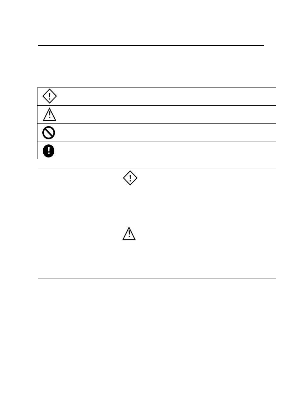
Danger
In case of incorrect handling, it indicates possibility of dangerous
situation could arise and that the possibility of death or serious illness
of a person is assumed.
Caution
In case of incorrect handling, it indicates possibility of dangerous
situation could arise and that the possibility of personal injury or
property damage is assumed.
Inhibition
This symbol is used to indicate a practice that shall not be attempted
Imposition
This symbol is used to indicate a practice that shall be done.
Danger
● Never touch any terminals and internal parts that is in active status. Could cause electric shocks.
● Do not pull or bend the cable, or place heavy objects on it. Could cause electric shocks or a fire.
● Never touch part of rotating. Could cause personal injury by involving to the rotor.
● Never touch surface of motors or power elements because those are may become abnormally high
temperature while driving. Could cause burns.
Caution
● Don't use in the place where water, oil, or chemicals is splashed, or in the place where is corrosive
environment or flammable gas.
● Use the rated power supply voltage. Could cause a fire.
● Do not touch the surface-mounted component on the board, as it may be hot while turning on the power
or while after just shutting off the power. Could cause burn injury.
● Wiring work should be done correctly.
― Safety Precautions ―
For safe use of SD4030B3, following icons and messages are used in this manual to indicate safety
precautions. The precautions given here indicates serious safety contents. You are recommended to
observe the safety precautions fully.
Page 5

Inhibition
● Don't use or store in the place under direct sunshine.
● Don't use or store in the place where may be beyond the range of ambient temperature and relative
humidity specification.
● Do not use or store in the place with many dust, dirt and others.
● Do not use or store in the place subject to direct vibration or shock.
● Never attempt to perform repair and modification by yourself.
Imposition
● Install an emergency stop circuit outside to be able to stop the system operation immediately.
Page 6

Table of Contents
1. Notes (Please be sure to read before using)·············································································· 1
1-1 Installation ····················································································································· 1
1-2 Connection of Connector ·································································································· 1
1-3 Division of Micro step······································································································· 1
1-4 Heat generation of a motor ······························································································· 1
1-5 Electric current value of Micro Step ···················································································· 1
1-6 Unipolar type motor drive ································································································· 1
1-7 Compatibility notice to the customers using SD4030B2. ·························································· 1
2. Specifications ····················································································································· 2
3. Connector pin assignment ····································································································· 3
3-1 CN1 ····························································································································· 3
3-2 CN2 ····························································································································· 3
4. I/O circuit diagram ················································································································ 4
4-1 Command pulse or CW pulse (P+, P-), Direction Command or CCW pulse (D+, D-) Input ············· 4
4-2 Excitation off (OFF) input ·································································································· 4
4-3 Alarm (ALM) Output········································································································· 4
5. Logic of Command Input pulse ······························································································· 5
5-1 In case of 1-pulse mode ··································································································· 5
5-2 In case of 2-pulses mode ································································································· 5
6. Connection of Motor ············································································································· 6
6-1 In the case of Bipolar type motor ························································································ 6
6-2 In the case of Unipolar type motor ······················································································ 6
7. Setting of switch SW 1 ·········································································································· 7
8. Setting of switch SW 3(MIX) ·································································································· 8
9. Settings of Jumper JP1 ········································································································· 9
10. LED“POW” ····················································································································· 10
11. JOG operation ················································································································· 10
12. Setting of potentiometers ··································································································· 10
12-1 RUN potentiometer ······································································································ 10
12-2 STOP potentiometer ····································································································· 11
12-3 JOG potentiometer ······································································································· 11
13. How to adjust the RUN potentiometer precisely ······································································ 12
14. Need of a rated output current reduction at a higher power supply voltage area ···························· 12
15. Troubleshooting ··············································································································· 13
16. Component layout ············································································································ 14
17. Dimension ······················································································································ 15
18. Difference between SD4030B2 and SD4030B3 ······································································ 16
18-1 Difference in how to set Mix Decay ················································································· 16
18-2 Difference on the maximum frequency of Command pulse ·················································· 16
19. CE Marking ····················································································································· 17
20. Caution for ESD damage ··································································································· 17
Page 7

1
1.Notes (Please be sure to read before using)
1-1 Installation
You shall observe the following installation method when installing this driver.
Please install the driver in the place where the air around the driver within 5 cm has air convection
with a rated temperature (40 ° C or lower temperature).
When using multiple axes please leave a space of 10 mm or more between each driver.
1-2 Connection of Connector
In particular, please pay attention to power wiring. This driver has a power circuit configuration that resists
breaking even with the incorrect polarity of the power supply, but the driver will be damaged if you wire the
power supply to the motor output terminal.
Please observe the instruction about wire materials and a length of stripped bare wire that is shown in the
section 3.. Also, tighten the terminal block screw with a torque of 0.22 to 0.24 Nm. This prevents loosening
of screws and disconnection of wires.
1-3 Division of Micro step
Since a Division of Micro Step is performed by vector splitting currents of Phase A and Phase B of a stepping
motor by approximate sinusoidal wave electrically, a divided one-step-angle does not guarantee a
mechanical position accuracy as is.
The mechanical positional accuracy depends upon the machine accuracy of a motor's own and a driven
device.
1-4 Heat generation of a motor
Since surface of a motor may become extremely high temperature while driving, please care burns.
If a surface temperature of a motor exceeds 100℃, the motor may be damaged. So then reduce the current
value with "RUN “potentiometer or cool the motor by forced air cooling to not exceed 100 ℃.
It also can prevent heat generation by enabling Auto Current Down function and reducing a current during
stop.
1-5 Electric current value of Micro Step
A setting electric current value by "RUN" potentiometer is a peak value of approximate sinusoidal current.
1-6 Unipolar type motor drive
Although this driver is mainly designed for bipolar type motors, it can also drive unipolar type motors.
Please refer to the section 6-2 for wire connection method.
1-7 Compatibility notice to the customers using SD4030B2. This driver is upward compatible with SD4030B2, but Mix Decay setting has been changed from a potentiometer to a switch. For more detailed information, Refer to the section 18. Outer form size and installation mounting pitch has not be changed.
Page 8

2
Item
Definition
Note
Model
SD4030B3
Input power supply
voltage
+ 18V to 36V
Supply current
3A(MAX)
When the output current is set to 3 A
Applicable motor
2-phase stepping motors (bipolar
type)
Unipolar type motors also can be
driven.
Output current
0.5 to 3Ao-p(±5%)/phase
Driving method
Bipolar constant current chopper
method
Current Down function
Auto Current Down
Reduce current to the current value
set by “STOP” potentiometer in 0.25
to 1 second after stopping the pulse.
Function is selectable by the switch
Maximum input pulse
frequency
200Kpps
Adjustment
by the
trimmer
RUN
Set the excitation current (0.5 to 3A)
The factory setting is 2A
STOP
Set the current of Current Down
mode
10% to 60% of the RUN current
JOG
Set the speed of JOG
300pps to 14Kpps
Function
select by
the switch
SW-1,2,3
Select of division number
1/2,1/8,1/10,1/16,1/20,1/32,1/40,1/64
SW-4
Enable/disable Auto Current Down
ON: Enable, OFF: Disable
The factory setting is Enable.
SW-5,6
Select of JOG function
SW-5 ON: Enable JOG
SW-6 ON: CW, OFF: CCW
SW3
Select Mix Decay ratio
JP1
Select 1-pulse, 2-pulses
Input
signal
P+,P-
Command pulse or Command CW
pulse
1-pulse or 2-pulses is selectable as
command pulse
Inputs are isolated by photo couplers
D+,D-
Command pulse or Command CCW
pulse
OFF+,OFF-
Excitation OFF
Output
signal
ALM+,ALM-
Alarm (Power elements overheat
detection)
The signal outputs when the
temperature of inside power
elements reach to 170℃ (Typ).
Output are isolated by photo
couplers
ON: Normal, OFF: Alarm
Dimension
W90×D55.5×H28
Wight
112g
Including the terminal block socket
Operating temperature,
humidity
0 to 40℃, 35 to 80%
No condensation
Storage temperature,
humidity
-20 to + 85 C, 35 to 80%
No condensation
CE Marking
Self-declaration
GATEGORY 9
2.Specifications
Page 9

3
No.
Signal name
Definition
IN/OUT
6
/B
Motor Phase /B
OUT 5 B
Motor Phase B
OUT 4 /A
Motor Phase /A
OUT 3 A
Motor Phase A
OUT
2
0V
Input Power supply 0V
IN
1
+V
Power supply plus input (18V
to 36V)
IN
No.
Signal
name
Definition
IN/OUT
8
ALM-
Power element overheat
alarm. (OFF at Alarm)
OUT
7
ALM+
OUT
6
OFF-
Input Excitation OFF
IN 5 OFF+
IN
4
D-
Input Direction Command or
CCW pulse
IN
3
D+
IN
2
P-
Input Command pulse or CW
pulse
IN 1 P+
IN
6 to 7mm
Do not pre-solder to the wire tip!
(You will not be able to wire
connection correctly.)
3.Connector pin assignment
3-1 CN1
Applicable terminal block: MC1.5/6-ST-3.5 (Phoenix contact)
3-2 CN2
Applicable terminal block: MC1.5/8-ST-3.5 (Phoenix contact)
Note 1) Be careful not to mistake the pin number especially for power supply and motor wiring.
Note 2) Applicable wire size: AWG 28 to AWG 16 (stranded wire)
The length of the stripped bare wire: 6 to 7mm
Page 10

4
270Ω
5mA≦IL≦30mA
TLP291GB(東芝)
又は相当品
+5V
0V
IL
+24V
0.5W,2kΩ (注)
OFF+
OFF-
TLP281 GB( 東芝)
又は相当品
+
-
VCE
Io
Io ≦ 4mA
VCE ≦ 50Vmax
270Ω
+
-
AM26LS31相当品
P+,D+
P-,D-
2mA≦IL≦13mA
IL
TLP2358(東芝)又は相当品
270Ω
TLP2358(東芝)又は相当品
2mA≦IL≦13mA
IL
+
-
+5V
0V
P+,D+
P-,D-
+24V
0.5W,2kΩ(注1)
(Note)
TLP2358 (Toshiba) or compatible parts
AM26LS31
or compatible parts
TLP2358 (Toshiba) or compatible parts
TLP281GB (Toshiba) or compatible parts
(Note)
TLP291GB (Toshiba) or compatible parts
4.I/O circuit diagram
4-1 Command pulse or CW pulse (P+, P-), Direction Command or CCW pulse (D+, D-) Input In case of Open collector driven
Note 1) When circuit is driven at + 24V, connect a resistor of 1 W, 2 kΩ (recommend) in series.
When using a resistor other than 2 kΩ, use the resistance value that satisfies the current value in the
figure.
Note 2) In case of Open collector driven, the cable length should be within 1m.
In case of Line driver driven
4-2 Excitation off (OFF) input
Note) When circuit is driven at + 24V, connect a resistor of 0.5W, 2 kΩ (recommend) in series.
When using a resistor other than 2 kΩ, use the resistance value that satisfies the current value in the
figure.
4-3 Alarm (ALM) Output
Page 11

5
CW
CCW
t1 t2 t3 t4
T1,t2,t3,t4 ≧ 2.5μ sec
P1-
P2-
t1 t2 t4 t5t3
T1,t2,t3,t4,t5 ≧ 2.5μsec
CW
CCW
P1-
P2-
5.Logic of Command Input pulse
5-1 In case of 1-pulse mode Command pulse is counted at Up-edge of the internal photo coupler outputs. When a motor is in a normal connection, Command Direction is; CW when the internal photo coupler output is "LOW" and CCW when the internal photo coupler output is "HIGH". Output of the photo coupler is LOW when the primary LED is ON. Please note that direction of motor rotation varies also by wire connection. Timing chart is shown in the following figure.
5-2 In case of 2-pulses mode Command pulse is counted at Up-edge of photo coupler outputs. Each input becomes stand-by mode at the high level (photo coupler OFF). A motor rotates CW direction by pulses input to P1, or rotates CCW direction by the pulses input to P2. Please note that direction of motor rotation varies also by wire connection. Timing chart is shown in the following figure.
Page 12

6
A相コイル
B相コイル
ステッピ ングモータ
/A相コイル
/B相コイル
COM
COM
A
/A
B
/B
CN1
/A相コイル
/B相コイル
ステッピングモータ
A相コイル
B相コイル
COM
COM
A
/A
B
/B
CN1
A
/A
B
/B
CN1
A相コイル
B相コイル
ステッピ ングモータ
Phase A
Phase B
Stepping motor (coil connection)
Stepping motor (coil connection)
Stepping motor (coil connection)
Phase A
Phase /A
Phase B
Phase /B
Phase A
Phase /A
Phase B
Phase /B
6.Connection of Motor
6-1 In the case of Bipolar type motor
6-2 In the case of Unipolar type motor Wiring method 1: With same current settings as a unipolar microstep driver, the torque and heat that is generated by a motor are almost the same. Please use this wiring method in usual.
Wiring method 2: It is effective method for using a motor at low speed with high torque. To make motor heat
generation equivalent to wiring method 1, please limit the maximum current to 70%.
However, the torque generated in the low speed range is 1.4 times of usual but an inductance of the coil is
four times than the method 1, a torque drops sharply against an increasing rotation speed.
Page 13

7
■ Setting of JOG operation
5 6 JOG rotation
☆
ON
ON
CW
ON
OFF
CCW
OFF
OFF
JOG disable
Caution) In case of pulse input operation,
be sure to set 5 and 6 to OFF.
■ Setting of Auto Current Down
4
☆
ON
Enable
OFF
Disable
■ Setting of Division Number
1 2 3
Division
number
ON
ON
ON
1/2
ON
ON
OFF
1/8
ON
OFF
ON
1/10
ON
OFF
OFF
1/16
OFF
ON
ON
1/20
OFF
ON
OFF
1/32
OFF
OFF
ON
1/40
OFF
OFF
OFF
1/64
☆
ON
7.Setting of switch SW 1
Page 14

8
SW setting
Slow Decay ratio
Motor rotation speed
80%
Slower
Faster
40%
20%
0%
PWM波形
電流波形
T1 T2
T3
T1 : スローディケイ
T2: ファーストディケイ
T3: 減衰周期
スローディケイ比率 = T1 / T3 ×100 (%)
ON ON
ON OFF
OFF ON
OFF OFF
Current waveform
PWM waveform
1 2
ON
1 2
ON
1 2
ON
1 2
ON
T1 : Slow Decay
Slow Decay Ratio = T1 /T3 x 100 (%)
8.Setting of switch SW 3(MIX)
Four types of setting are possible with the switch for adjusting Mix Decay function.
Mix Decay function has effect of reducing vibration of a motor by controlling slope of electric current
attenuation within a PWM cycle. Since the optimum ratio of Slow Decay setting at each motor rotation speed
is different, it is recommended that a customer may select the optimum switch position while checking
vibration at the motor speed you need.
In general, vibration declines when a Slow Decay ratio is larger at ultra-low speed area. On the other hand,
vibration declines when set a Slow Decay ratio smaller at a faster rotation speed.
T2 : Fast Decay
T3 : Decay Cycle
Page 15

9
2
1
6
5
2
1
6
5
9.Settings of Jumper JP1
Set according to Command pulse type. The factory setting is 1-pulse.
●In case of 1-pulse mode (pulse, direction) ●In case of 2-pulses mode (CW pulse, CCW pulse)
1-3, 2-4 short 3-5, 4-6 short
Page 16

10
1. 7A
1. 3A
2A
2. 4A
1A
0. 8A
2. 7A
3A
“RUN” potentiometer
10.LED“POW”
LED lights green when power is turned on. If the LED does not light even when power is turned on, there is
a possibility that Polarity of the power supply connected may be reversed, or that the power module may
have been damaged by wiring mistake.
Since this driver has a power circuit configuration that resists breaking even with the incorrect polarity of the
power supply, please turn the power on again after correcting the connection. If the power module is broken,
a whole unit shall be replaced.
Regarding location of the LED, refer layout diagram in the page 14 .
11.JOG operation
JOG operation by PUSH switch becomes enable when SW1-5 is ON.
When performing JOG operation, remove CN2, and set JP1 to 1-pulse mode.
Select Direction of rotation with SW1 - 6, and change a pulse frequency with "JOG" potentiometer.
JOG operation should be only used for trial operation of a driver and motor, and please operate with a motor
alone. Never use JOG operation after mounting this unit into other equipment, since it is dangerous to use
JOG operation then.
Be sure to turn off SW1-5 and 6 for normal Pulse Input operation
12.Setting of potentiometers
12-1 RUN potentiometer This potentiometer is for setting a peak current value during operation. The factory setting is 2A.
0. 5A
Page 17

11
630pps
“JOG” potentiometer
300pps
14Kpps
45%
36%
48%
52%
29%
22%
56%
60%
“STOP” potentiometer
12-2 STOP potentiometer This potentiometer is for setting a current value at the time of Auto Current Down. The setting value is a ratio to the setting value of RUN potentiometer.
12-3 JOG potentiometer Set a frequency value at JOG operation. The following frequency are only a guide, so please adjust the
10%
potentiometer while watching an actual motor rotation speed. Please note that an angle of the potentiometer
and a frequency do not change linearly, and it will rise sharply from near the center.
Page 18

12
2-phases
Stepping
motor
Power supply +
Power supply 0 V
+V
0V
Phase A
Phase A
Phase /A
Phase B
Phase /B
CN1
DC ammeter
+
-
Phase /B
Phase B
Phase /A
Peak
current
24V
3A
Power supply
voltage
36V
2. 5A
13.How to adjust the RUN potentiometer precisely
Prepare a DC ammeter. Before turning on the power supply, connect the positive side of the ammeter to the
phase A of connector CN1, and the negative side of the ammeter to the phase A of a motor. Turn off SW1-4
of the driver.
Then turn on the power supply and adjust with the RUN potentiometer to a target current value.
14.Need of a rated output current reduction at a higher power supply voltage area
When a power supply voltage exceeds 24 V and a motor is used in continuous rotation, please reduce a
peak current value according to the graph below.
Page 19

13
Symptom
Cause
Inspection / Corrective action
Motor does not turn
Command pulse is not input
Please check the host controller side
Motor does not invert rotate
direction even switching CW / CCW
pulse input.
Please short 3-5, 4-6 of jumper JP 1
It is in JOG mode
Please turn off 5, 6 of DIP switch SW1
Motor temperature
becomes
abnormally high
during rotation.
RUN potentiometer setting is too
high for the rated current of the
motor.
Please reduce down RUN potentiometer.
Motor temperature
becomes
abnormally high
during stop.
Auto Current Down is disabled.
Please turn on SW1-4
15.Troubleshooting
Page 20

14
LED POW
“STOP” potentiometer
“RUN” potentiometer
PUSH switch for JOG
Jumper JP1
“JOG” potentiometer
CN2
Switch SW3
Switch SW1
CN1
16.Component layout
Page 21

15
RUN
STOP
JOG
JOG
CN1 CN2
1
6
JP1
1
P+
P-
D+
D-
OFF+
OFF-
ALM+
ALM-
+V
0V
A
/A
B
/B
1
2
4
82(取り付け用)
4
90
4
44.5(取り付け用)
7
55.5
10
28
82(取り付け用)
2-φ4
2-φ4
MIX
(Mounting holes)
(Mounting holes)
17.Dimension
Page 22

16
Slow Decay ratio
SD4030B2
SD4030B3
Settings of MIX potentiometer
Position of SW3
80%
(Factory setting)
40%
20%
0%
SD4030B2
SD4030B3
Maximum input pulse
frequency
100Kpps
200Kpps
OFF OFF
OFF ON
ON OFF
ON ON
0
5
7
10
1 2
ON
1 2
ON
1 2
ON
1 2
ON
18.Difference between SD4030B2 and SD4030B3
18-1 Difference in how to set Mix Decay The Mix Decay setting has been changed from a potentiometer to a switch. Customers already using SD4030B2 are recommended to refer to the following compatibility chart for setting SD4030B3.
Compatibility table of Mix Decay potentiometer setting and switch setting
Note) For Mix Decay, see page 7, section 7. Switch SW3 (MIX) setting.
18-2 Difference on the maximum frequency of Command pulse
Page 23

17
EMC Directive
Emission
EN61000-6-4:2007+A1:2011
Immunity
EN61000-6-2:2005
RoHS Directive
EN50581:2012
19.CE Marking
SD4030B3 had performed tests for a driver and a motor individually that based on the following standards,
and had made the self-declaration of CE marking.
As for the EMC directive conformity, hence a condition varies depending on a customer's equipment
configuration with this driver and motor installed, so the customer should confirm the conformity of whole
devices by your own responsibility.
20.Caution for ESD damage
ElectroStatic Discharge may cause malfunction of, or damage on the driver.
When the driver power is on, do not touch directly potentiometers and switches with bare hands.
When changing the setting on the potentiometers and switches, use an insulated screwdriver.
Page 24

ME Division, Vanguard systems Inc.
1-27-23 Higashi-Tokorozawa, Tokorozawa-City, Saitama,
359-0021 JAPAN
TEL +81-4-2951-5381, FAX +81-4-2951-5383
URL:http://www.hp-vanguard.com
 Loading...