

Page 1

HPE FlexNetwork 7500 Switch Series
IP Multicast Configuration Guide
P
Software
Document version: 6W100-20161230
art number: 5200-1936
version: 7500-CMW710-R7524
Page 2

© Copyright 2016 Hewlett Packard Enterprise Development LP
The information contained herein is subject to change without notice. The only warranties for Hewlett Packard
Enterprise products and services are set forth in the express warranty statements accompanying such
products and services. Nothing herein should be construed as constituting an additional warranty. Hewlett
Packard Enterprise shall not be liable for technical or editorial errors or omissions contained herein.
Confidential computer software. Valid license from Hewlett Packard Enterprise required for possession, use, or
copying. Consistent with FAR 12.211 and 12.212, Commercial Computer Software, Computer Software
Documentation, and Technical Data for Commercial Items are licensed to the U.S. Government under vendor’s
standard commercial license.
Links to third-party websites take you outside the Hewlett Packard Enterprise website. Hewlett Packard
Enterprise has no control over and is not responsible for information outside the Hewlett Packard Enterprise
website.
Acknowledgments
Intel®, Itanium®, Pentium®, Intel Inside®, and the Intel Inside logo are trademarks of Intel Corporation in the
United States and other countries.
Microsoft® and Windows® are trademarks of the Microsoft group of companies.
Adobe® and Acrobat® are trademarks of Adobe Systems Incorporated.
Java and Oracle are registered trademarks of Oracle and/or its affiliates.
UNIX® is a registered trademark of The Open Group.
Page 3

Contents
Multicast overview ························································································· 1
Introduction to multicast ····································································································································· 1
Information transmission techniques ·········································································································· 1
Multicast features ······································································································································· 3
Common notations in multicast ·················································································································· 4
Multicast benefits and applications ············································································································ 4
Multicast models ················································································································································ 4
Multicast architecture ········································································································································· 5
Multicast addresses ··································································································································· 5
Multicast protocols ····································································································································· 8
Multicast packet forwarding mechanism ·········································································································· 10
Multicast support for VPNs······························································································································· 11
Introduction to VPN instances ·················································································································· 11
Multicast application in VPNs ··················································································································· 12
Configuring IGMP snooping ········································································· 13
Overview ·························································································································································· 13
IGMP snooping ports ······························································································································· 13
How IGMP snooping works ······················································································································ 15
IGMP snooping proxying ·························································································································· 16
Protocols and standards ·························································································································· 17
Configuration restrictions and guidelines ································································································· 17
IGMP snooping configuration task list ·············································································································· 17
IGMP snooping configuration task list for VLANs ···················································································· 18
IGMP configuration task list for VSIs········································································································ 18
Configuring basic IGMP snooping features ····································································································· 19
Enabling IGMP snooping ························································································································· 19
Specifying an IGMP snooping version ····································································································· 20
Setting the maximum number of IGMP snooping forwarding entries ······················································· 20
Configuring static multicast MAC address entries ···················································································· 21
Setting the IGMP last member query interval ·························································································· 21
Configuring IGMP snooping port features ········································································································ 22
Setting aging timers for dynamic ports ····································································································· 22
Configuring static ports ···························································································································· 23
Configuring a port as a simulated member host ······················································································ 24
Enabling fast-leave processing ················································································································ 24
Disabling a port from becoming a dynamic router port ············································································ 25
Configuring the IGMP snooping querier ··········································································································· 25
Configuration prerequisites ······················································································································ 26
Enabling the IGMP snooping querier ······································································································· 26
Configuring parameters for IGMP general queries and responses ·························································· 26
Enabling IGMP snooping proxying ··················································································································· 27
Configuring parameters for IGMP messages ··································································································· 27
Configuration prerequisites ······················································································································ 27
Configuring the source IP address for IGMP messages ·········································································· 28
Setting the 802.1p priority for IGMP messages ······················································································· 29
Configuring IGMP snooping policies ················································································································ 30
Configuring a multicast group policy ········································································································ 30
Enabling multicast source port filtering ···································································································· 31
Enabling dropping unknown multicast data ······························································································ 31
Enabling IGMP report suppression ·········································································································· 32
Setting the maximum number of multicast groups on a port ···································································· 32
Enabling multicast group replacement ····································································································· 33
Enabling host tracking ······························································································································ 34
Displaying and maintaining IGMP snooping ···································································································· 34
IGMP snooping configuration examples ·········································································································· 36
Group policy and simulated joining configuration example (for VLANs) ·················································· 36
i
Page 4

Static port configuration example (for VLANs) ························································································· 38
IGMP snooping querier configuration example (for VLANs) ···································································· 40
IGMP snooping proxying configuration example (for VLANs) ·································································· 43
IGMP snooping configuration example (for VXLANs) ·············································································· 44
Troubleshooting IGMP snooping ····················································································································· 49
Layer 2 multicast forwarding cannot function ··························································································· 49
Multicast group policy does not work ······································································································· 50
Configuring PIM snooping ············································································ 51
Overview ·························································································································································· 51
Configuring PIM snooping ································································································································ 52
Displaying and maintaining PIM snooping ······································································································· 53
PIM snooping configuration example ··············································································································· 53
Network requirements ······························································································································ 53
Configuration procedure ··························································································································· 54
Verifying the configuration ························································································································ 55
Troubleshooting PIM snooping ························································································································ 57
PIM snooping does not work on a Layer 2 device ··················································································· 57
Configuring multicast VLANs ······································································· 58
Overview ·························································································································································· 58
Multicast VLAN configuration task list ·············································································································· 60
Configuring a sub-VLAN-based multicast VLAN ······························································································ 60
Configuration prerequisites ······················································································································ 60
Configuration restrictions and guidelines ································································································· 60
Configuration procedure ··························································································································· 61
Configuring a port-based multicast VLAN ········································································································ 61
Configuration prerequisites ······················································································································ 61
Configuring user port attributes ················································································································ 61
Assigning user ports to a multicast VLAN ································································································ 62
Setting the maximum number of multicast VLAN forwarding entries ······························································· 62
Displaying and maintaining multicast VLANs ··································································································· 63
Multicast VLAN configuration examples ·········································································································· 63
Sub-VLAN-based multicast VLAN configuration example ······································································· 63
Port-based multicast VLAN configuration example ·················································································· 66
Configuring multicast routing and forwarding ··············································· 70
Overview ·························································································································································· 70
RPF check mechanism ···························································································································· 70
Static multicast routes ······························································································································ 72
Multicast forwarding across unicast subnets ···························································································· 73
Configuration task list ······································································································································· 74
Enabling IP multicast routing···························································································································· 74
Configuring multicast routing and forwarding ··································································································· 75
Configuring static multicast routes ··········································································································· 75
Specifying the longest prefix match principle ··························································································· 75
Configuring multicast load splitting··········································································································· 76
Configuring a multicast forwarding boundary ··························································································· 76
Enabling multicast forwarding between sub-VLANs of a super VLAN ····························································· 76
Displaying and maintaining multicast routing and forwarding ·········································································· 77
Configuration examples ··································································································································· 79
Changing an RPF route ··························································································································· 79
Creating an RPF route ····························································································································· 81
Multicast forwarding over a GRE tunnel ··································································································· 82
Troubleshooting multicast routing and forwarding ··························································································· 85
Static multicast route failure ····················································································································· 85
Configuring IGMP ························································································ 86
Overview ·························································································································································· 86
IGMPv1 overview ····································································································································· 86
IGMPv2 enhancements ···························································································································· 87
IGMPv3 enhancements ···························································································································· 88
ii
Page 5

IGMP SSM mapping ································································································································ 89
IGMP proxying ········································································································································· 90
IGMP support for VPNs ···························································································································· 91
Protocols and standards ·························································································································· 91
IGMP configuration task list ····························································································································· 92
Configuring basic IGMP features ····················································································································· 92
Enabling IGMP ········································································································································· 92
Specifying an IGMP version ····················································································································· 93
Configuring a static group member ·········································································································· 93
Configuring a multicast group policy ········································································································ 93
Adjusting IGMP performance ··························································································································· 94
Configuring IGMP query and response parameters ················································································· 94
Enabling fast-leave processing ················································································································ 96
Configuring IGMP SSM mappings ··················································································································· 97
Configuration prerequisites ······················································································································ 97
Configuration procedure ··························································································································· 97
Configuring IGMP proxying ······························································································································ 97
Configuration prerequisites ······················································································································ 97
Enabling IGMP proxying ·························································································································· 97
Enabling multicast forwarding on a non-querier interface ········································································ 98
Configuring multicast load splitting on an IGMP proxy············································································· 98
Enabling IGMP NSR ········································································································································ 99
Displaying and maintaining IGMP ···················································································································· 99
IGMP configuration examples ························································································································ 100
Basic IGMP features configuration examples ························································································ 100
IGMP SSM mapping configuration example ·························································································· 102
IGMP proxying configuration example ··································································································· 105
Troubleshooting IGMP ··································································································································· 106
No membership information on the receiver-side router ········································································ 106
Inconsistent membership information on the routers on the same subnet············································· 106
Configuring PIM ························································································· 108
Overview ························································································································································ 108
PIM-DM overview ··································································································································· 108
PIM-SM overview ··································································································································· 110
BIDIR-PIM overview ······························································································································· 116
Administrative scoping overview ············································································································ 119
PIM-SSM overview ································································································································· 121
Relationship among PIM protocols ········································································································ 122
PIM support for VPNs ···························································································································· 123
Protocols and standards ························································································································ 123
Configuring PIM-DM······································································································································· 123
PIM-DM configuration task list ··············································································································· 124
Configuration prerequisites ···················································································································· 124
Enabling PIM-DM ··································································································································· 124
Enabling the state refresh feature ·········································································································· 124
Configuring state refresh parameters ····································································································· 125
Configuring PIM-DM graft retry timer ····································································································· 125
Configuring PIM-SM ······································································································································· 126
PIM-SM configuration task list················································································································ 126
Configuration prerequisites ···················································································································· 126
Enabling PIM-SM ··································································································································· 126
Configuring an RP ·································································································································· 127
Configuring a BSR ································································································································· 129
Configuring multicast source registration ······························································································· 131
Configuring the switchover to SPT ········································································································· 132
Configuration restrictions and guidelines ······························································································· 132
BIDIR-PIM configuration task list ··········································································································· 132
Configuration prerequisites ···················································································································· 133
Enabling BIDIR-PIM ······························································································································· 133
Configuring an RP ·································································································································· 133
Configuring a BSR ································································································································· 135
iii
Page 6

Configuring PIM-SSM ···································································································································· 137
PIM-SSM configuration task list ············································································································· 138
Configuration prerequisites ···················································································································· 138
Enabling PIM-SM ··································································································································· 138
Configuring the SSM group range ·········································································································· 138
Configuring common PIM features················································································································· 139
Configuration task list ····························································································································· 139
Configuration prerequisites ···················································································································· 139
Configuring a multicast source policy ····································································································· 139
Configuring a PIM hello policy················································································································ 140
Configuring PIM hello message options ································································································· 140
Configuring common PIM timers ············································································································ 142
Setting the maximum size of a join or prune message ·········································································· 143
Enabling BFD for PIM ···························································································································· 143
Enabling PIM passive mode ··················································································································· 143
Enabling PIM NSR ································································································································· 144
Enabling SNMP notifications for PIM ····································································································· 144
Setting a DSCP value for outgoing PIM messages ················································································ 144
Displaying and maintaining PIM ····················································································································· 145
PIM configuration examples ··························································································································· 145
PIM-DM configuration example ·············································································································· 145
PIM-SM non-scoped zone configuration example ················································································· 148
PIM-SM admin-scoped zone configuration example·············································································· 151
BIDIR-PIM configuration example ·········································································································· 156
PIM-SSM configuration example············································································································ 160
Troubleshooting PIM ······································································································································ 163
A multicast distribution tree cannot be correctly built ············································································· 163
Multicast data is abnormally terminated on an intermediate router························································ 164
An RP cannot join an SPT in PIM-SM ···································································································· 164
An RPT cannot be built or multicast source registration fails in PIM-SM ··············································· 164
Configuring MSDP ····················································································· 166
Overview ························································································································································ 166
How MSDP works ·································································································································· 166
MSDP support for VPNs ························································································································ 171
Protocols and standards ························································································································ 171
MSDP configuration task list ·························································································································· 172
Configuring basic MSDP features ·················································································································· 172
Configuration prerequisites ···················································································································· 172
Enabling MSDP ······································································································································ 172
Specifying an MSDP peer ······················································································································ 173
Configuring a static RPF peer ················································································································ 173
Configuring an MSDP peering connection ····································································································· 173
Configuration prerequisites ···················································································································· 173
Configuring a description for an MSDP peer ·························································································· 174
Configuring an MSDP mesh group ········································································································ 174
Controlling MSDP peering connections ································································································· 174
Configuring SA message-related parameters ································································································ 175
Configuration prerequisites ···················································································································· 175
Enabling multicast data encapsulation in SA messages ········································································ 175
Configuring the originating RP of SA messages ···················································································· 176
Configuring SA request messages ········································································································· 176
Configuring SA message policies ·········································································································· 177
Configuring the SA cache mechanism ··································································································· 178
Enabling MSDP NSR ····································································································································· 178
Displaying and maintaining MSDP ················································································································· 178
MSDP configuration examples ······················································································································· 179
PIM-SM inter-domain multicast configuration ························································································ 179
Inter-AS multicast configuration by leveraging static RPF peers ··························································· 184
Anycast RP configuration ······················································································································· 188
SA message filtering configuration ········································································································· 192
Troubleshooting MSDP ·································································································································· 195
iv
Page 7

MSDP peers stay in disabled state ········································································································ 196
No SA entries exist in the router's SA message cache ·········································································· 196
No exchange of locally registered (S, G) entries between RPs ····························································· 196
Configuring multicast VPN ········································································· 197
Overview ························································································································································ 197
MD VPN overview ·································································································································· 198
Protocols and standards ························································································································ 201
How MD VPN works······································································································································· 201
Default-MDT establishment ···················································································································· 202
Default-MDT-based delivery ·················································································································· 205
MDT switchover ····································································································································· 208
Inter-AS MD VPN ··································································································································· 209
Configuration restrictions and guidelines ······································································································· 212
Multicast VPN configuration task list ·············································································································· 212
Configuring MD VPN ······································································································································ 213
Configuration prerequisites ···················································································································· 213
Enabling IP multicast routing for a VPN instance ··················································································· 213
Creating an MD for a VPN instance ······································································································· 214
Create an MD address family················································································································· 214
Specifying the default-group ·················································································································· 215
Specifying the MD source interface ······································································································· 215
Configuring MDT switchover parameters ······························································································· 216
Configuring the RPF vector feature ········································································································ 216
Enabling data-group reuse logging ········································································································ 217
Configuring BGP MDT ··································································································································· 217
Configuration prerequisites ···················································································································· 217
Configuring BGP MDT peers or peer groups ························································································· 217
Configuring a BGP MDT route reflector ································································································· 218
Displaying and maintaining multicast VPN····································································································· 219
Multicast VPN configuration examples··········································································································· 219
Intra-AS MD VPN configuration example ······························································································· 219
MD VPN inter-AS option B configuration example ················································································· 233
MD VPN inter-AS option C configuration example ················································································· 247
Troubleshooting MD VPN ······························································································································ 260
A default-MDT cannot be established ···································································································· 260
An MVRF cannot be created ·················································································································· 260
Configuring MLD snooping ········································································ 262
Overview ························································································································································ 262
MLD snooping ports ······························································································································· 262
How MLD snooping works ····················································································································· 264
MLD snooping proxying ························································································································· 265
Protocols and standards ························································································································ 266
Configuration restrictions and guidelines ······································································································· 266
MLD snooping configuration task list ············································································································· 267
MLD snooping configuration task list for VLANs ···················································································· 267
MLD snooping configuration task list for VSIs························································································ 267
Configuring basic MLD snooping features ····································································································· 268
Enabling MLD snooping ························································································································· 268
Specifying an MLD snooping version ····································································································· 269
Setting the maximum number of MLD snooping forwarding entries ······················································ 270
Configuring static IPv6 multicast MAC address entries ········································································· 270
Setting the MLD last listener query interval ···························································································· 271
Configuring MLD snooping port features ······································································································· 271
Setting aging timers for dynamic ports ··································································································· 272
Configuring static ports ·························································································································· 272
Configuring a port as a simulated member host ···················································································· 273
Enabling fast-leave processing ·············································································································· 273
Disabling a port from becoming a dynamic router port ·········································································· 274
Configuring the MLD snooping querier ·········································································································· 275
Configuration prerequisites ···················································································································· 275
v
Page 8

Enabling the MLD snooping querier ······································································································· 275
Configuring parameters for MLD general queries and responses ························································· 276
Enabling MLD snooping proxying ·················································································································· 276
Configuring parameters for MLD messages ·································································································· 277
Configuration prerequisites ···················································································································· 277
Configuring source IPv6 addresses for MLD messages ········································································ 277
Setting the 802.1p priority for MLD messages ······················································································· 279
Configuring MLD snooping policies················································································································ 279
Configuring an IPv6 multicast group policy ···························································································· 280
Enabling IPv6 multicast source port filtering ·························································································· 280
Enabling dropping unknown IPv6 multicast data ··················································································· 281
Enabling MLD report suppression ·········································································································· 282
Setting the maximum number of IPv6 multicast groups on a port ·························································· 282
Enabling IPv6 multicast group replacement ··························································································· 282
Enabling host tracking ···························································································································· 283
Displaying and maintaining MLD snooping ···································································································· 284
MLD snooping configuration examples ·········································································································· 285
IPv6 group policy and simulated joining configuration example (for VLANs) ········································· 285
Static port configuration example (for VLANs) ······················································································· 287
MLD snooping querier configuration example (for VLANs) ···································································· 290
MLD snooping proxying configuration example (for VLANs) ································································· 293
MLD snooping configuration example (for VXLANs)·············································································· 294
Troubleshooting MLD snooping ····················································································································· 299
Layer 2 multicast forwarding cannot function ························································································· 299
IPv6 multicast group policy does not work ····························································································· 300
Configuring IPv6 PIM snooping ································································· 301
Overview ························································································································································ 301
Configuring IPv6 PIM snooping······················································································································ 302
Displaying and maintaining IPv6 PIM snooping ····························································································· 303
IPv6 PIM snooping configuration example (for VLANs) ················································································· 303
Network requirements ···························································································································· 303
Configuration procedure ························································································································· 304
Verifying the configuration ······················································································································ 306
Troubleshooting IPv6 PIM snooping ·············································································································· 307
IPv6 PIM snooping does not work on a Layer 2 device ········································································· 307
Configuring IPv6 multicast VLANs ····························································· 308
Overview ························································································································································ 308
IPv6 multicast VLAN configuration task list ···································································································· 310
Configuring a sub-VLAN-based IPv6 multicast VLAN ··················································································· 310
Configuration prerequisites ···················································································································· 310
Configuration guidelines ························································································································· 310
Configuration procedure ························································································································· 311
Configuring a port-based IPv6 multicast VLAN ······························································································ 311
Configuration prerequisites ···················································································································· 311
Configuring user port attributes ·············································································································· 311
Assigning user ports to an IPv6 multicast VLAN ···················································································· 312
Setting the maximum number of IPv6 multicast VLAN forwarding entries ····················································· 312
Displaying and maintaining IPv6 multicast VLANs························································································· 313
IPv6 multicast VLAN configuration examples ································································································ 313
Sub-VLAN-based IPv6 multicast VLAN configuration example ····························································· 313
Port-based IPv6 multicast VLAN configuration example········································································ 316
Configuring IPv6 multicast routing and forwarding ····································· 320
Overview ························································································································································ 320
RPF check mechanism ·························································································································· 320
IPv6 multicast forwarding across IPv6 unicast subnets ········································································· 322
Configuration task list ····································································································································· 322
Enabling IPv6 multicast routing ······················································································································ 322
Configuring IPv6 multicast routing and forwarding························································································· 323
Specifying the longest prefix match principle ························································································· 323
vi
Page 9

Configuring IPv6 multicast load splitting ································································································ 323
Configuring an IPv6 multicast forwarding boundary··············································································· 323
Enabling IPv6 multicast forwarding between sub-VLANs of a super VLAN ··········································· 324
Displaying and maintaining IPv6 multicast routing and forwarding ································································ 324
IPv6 multicast routing and forwarding configuration example ········································································ 326
Network requirements ···························································································································· 326
Configuration procedure ························································································································· 327
Verifying the configuration ······················································································································ 328
Configuring MLD ························································································ 330
Overview ························································································································································ 330
How MLDv1 works ································································································································· 330
MLDv2 enhancements ··························································································································· 332
MLD SSM mapping ································································································································ 333
MLD proxying ········································································································································· 334
MLD support for VPNs ··························································································································· 334
Protocols and standards ························································································································ 334
MLD configuration task list ····························································································································· 335
Configuring basic MLD features ····················································································································· 335
Enabling MLD ········································································································································· 335
Specifying an MLD version ···················································································································· 336
Configuring a static group member ········································································································ 336
Configuring an IPv6 multicast group policy ···························································································· 336
Adjusting MLD performance··························································································································· 337
Configuring MLD query and response parameters ················································································ 337
Enabling fast-leave processing ·············································································································· 339
Configuring MLD SSM mappings ··················································································································· 339
Configuration prerequisites ···················································································································· 340
Configuration procedure ························································································································· 340
Configuring MLD proxying······························································································································ 340
Configuration prerequisites ···················································································································· 340
Enabling MLD proxying ·························································································································· 340
Enabling IPv6 multicast forwarding on a non-querier interface ······························································ 341
Configuring IPv6 multicast load splitting on an MLD proxy ···································································· 341
Enabling MLD NSR ········································································································································ 342
Displaying and maintaining MLD···················································································································· 342
MLD configuration examples·························································································································· 342
Basic MLD features configuration examples ·························································································· 342
MLD SSM mapping configuration example ···························································································· 345
MLD proxying configuration example ····································································································· 347
Troubleshooting MLD ····································································································································· 349
No member information exists on the receiver-side router ···································································· 349
Inconsistent membership information on the routers on the same subnet············································· 349
Configuring IPv6 PIM ················································································· 350
Overview ························································································································································ 350
IPv6 PIM-DM overview ··························································································································· 350
IPv6 PIM-SM overview ··························································································································· 352
IPv6 BIDIR-PIM overview ······················································································································· 358
IPv6 administrative scoping overview ···································································································· 361
IPv6 PIM-SSM overview ························································································································ 363
Relationship among IPv6 PIM protocols ································································································ 364
IPv6 PIM support for VPNs ···················································································································· 365
Protocols and standards ························································································································ 365
Configuring IPv6 PIM-DM ······························································································································ 365
IPv6 PIM-DM configuration task list ······································································································· 366
Configuration prerequisites ···················································································································· 366
Enabling IPv6 PIM-DM ··························································································································· 366
Enabling the state refresh feature ·········································································································· 366
Configuring state refresh parameters ····································································································· 367
Configuring IPv6 PIM-DM graft retry timer ····························································································· 367
Configuring IPv6 PIM-SM······························································································································· 368
vii
Page 10

IPv6 PIM-SM configuration task list ······································································································· 368
Configuration prerequisites ···················································································································· 368
Enabling IPv6 PIM-SM ··························································································································· 368
Configuring an RP ·································································································································· 369
Configuring a BSR ································································································································· 371
Configuring IPv6 multicast source registration ······················································································· 373
Configuring the switchover to SPT ········································································································· 374
Configuring IPv6 BIDIR-PIM ·························································································································· 374
Configuration restrictions and guidelines ······························································································· 374
IPv6 BIDIR-PIM configuration task list ··································································································· 374
Configuration prerequisites ···················································································································· 375
Enabling IPv6 BIDIR-PIM ······················································································································· 375
Configuring an RP ·································································································································· 375
Configuring a BSR ································································································································· 377
Configuring IPv6 PIM-SSM ···························································································································· 379
IPv6 PIM-SSM configuration task list ····································································································· 379
Configuration prerequisites ···················································································································· 380
Enabling IPv6 PIM-SM ··························································································································· 380
Configuring the IPv6 SSM group range ································································································· 380
Configuring common IPv6 PIM features ········································································································ 381
Configuration task list ····························································································································· 381
Configuration prerequisites ···················································································································· 381
Configuring an IPv6 multicast source policy ·························································································· 381
Configuring an IPv6 PIM hello policy ····································································································· 382
Configuring IPv6 PIM hello message options ························································································ 382
Configuring common IPv6 PIM timers ···································································································· 383
Setting the maximum size of a join or prune message ·········································································· 385
Enabling BFD for IPv6 PIM ···················································································································· 385
Enabling IPv6 PIM passive mode ·········································································································· 385
Enabling IPv6 PIM NSR ························································································································· 386
Enabling SNMP notifications for IPv6 PIM ····························································································· 386
Displaying and maintaining IPv6 PIM············································································································· 387
IPv6 PIM configuration examples··················································································································· 387
IPv6 PIM-DM configuration example ······································································································ 387
IPv6 PIM-SM non-scoped zone configuration example ········································································· 390
IPv6 PIM-SM admin-scoped zone configuration example ····································································· 393
IPv6 BIDIR-PIM configuration example ·································································································· 399
IPv6 PIM-SSM configuration example ··································································································· 403
Troubleshooting IPv6 PIM ······························································································································ 406
A multicast distribution tree cannot be correctly built ············································································· 406
IPv6 multicast data is abnormally terminated on an intermediate router ··············································· 406
An RP cannot join an SPT in IPv6 PIM-SM ··························································································· 407
An RPT cannot be built or IPv6 multicast source registration fails in IPv6 PIM-SM ······························· 407
Document conventions and icons ······························································ 408
Conventions ··················································································································································· 408
Network topology icons ·································································································································· 409
Support and other resources ····································································· 410
Accessing Hewlett Packard Enterprise Support····························································································· 410
Accessing updates ········································································································································· 410
Websites ················································································································································ 411
Customer self repair ······························································································································· 411
Remote support ······································································································································ 411
Documentation feedback ······················································································································· 411
Index ·········································································································· 413
viii
Page 11
Multicast overview
Source
Receiver
Receiver
Receiver
Host A
Host B
Host C
Host D
Host E
Packets for Host B
Packets for Host D
Packets for Host E
IP network
Introduction to multicast
As a technique that coexists with unicast and broadcast, the multicast technique effectively
addresses the issue of point-to-multipoint data transmission. By enabling high-efficiency
point-to-multipoint data transmission over a network, multicast greatly saves network bandwidth and
reduces network load.
By using multicast technology, a network operator can easily provide bandwidth-critical and
time-critical information services. These services include live webcasting, Web TV , distance learning,
telemedicine, Web radio, and real-time video conferencing.
Information transmission techniques
The information transmission techniques include unicast, broadcast, and multicast.
Unicast
In unicast transmis sion, the information sourc e must send a se parate copy of inform ation to each
host that needs the inf ormation.
Figure 1 Unicast transmission
In Figure 1, Host B, Host D, and Host E need the information. A separate transmission channel must
be established from the information source to each of these hosts.
In unicast transmission, the traffic transmitted over the network is proportional to the number of hosts
that need the information. I f a large number of hosts need t he information, the inf ormation source
must send a separate copy of the same inform ation to each of these hosts. Sending many copies
can place a tremendous pressure on the information source and the network bandwidth.
Unicast is not suitable for batch transmission of information.
1
Page 12
Broadcast
Source
Receiver
Receiver
Receiver
Host A
Host B
Host C
Host D
Host E
Packets for all hosts
A network segment
In broadcast transmission, the information source sends information to all hosts on the subnet, even
if some hosts do not need the information.
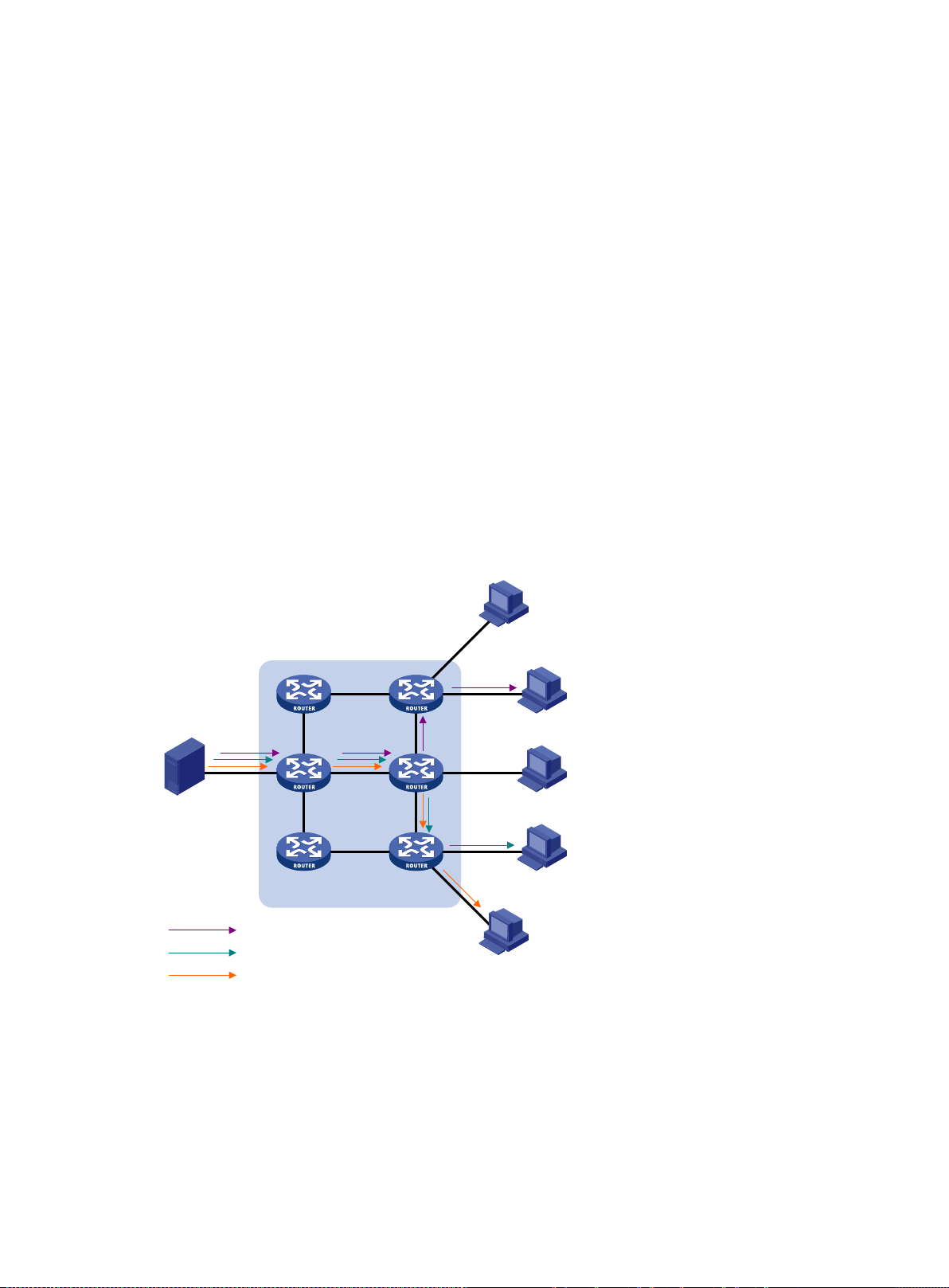
Figure 2 Broadcast transmission
Multicast
In Figure 2, only Host B, Host D, and Host E need the information. If the information is broadcast to
the subnet, Host A and Host C also receive it. In addition to information security issues, broadcasting
to hosts that do not need the information also causes traffic flooding on the same subnet.
Broadcast is disadvantageous in transmitting data to specific hosts. Moreover, broadcast
transmission is a significant waste of network resources.
Multicast provides point-to-m ultipoint data transmissions with the minimum networ k consumption.
When some hosts on the n etwork need multicast inf ormation, the inform ation sender, or multicast
source, sends only one copy of the information. Multicast distribution trees are built through multicast
routing protocols, and the packets are replicated only on nodes where the trees branch.
2
Page 13
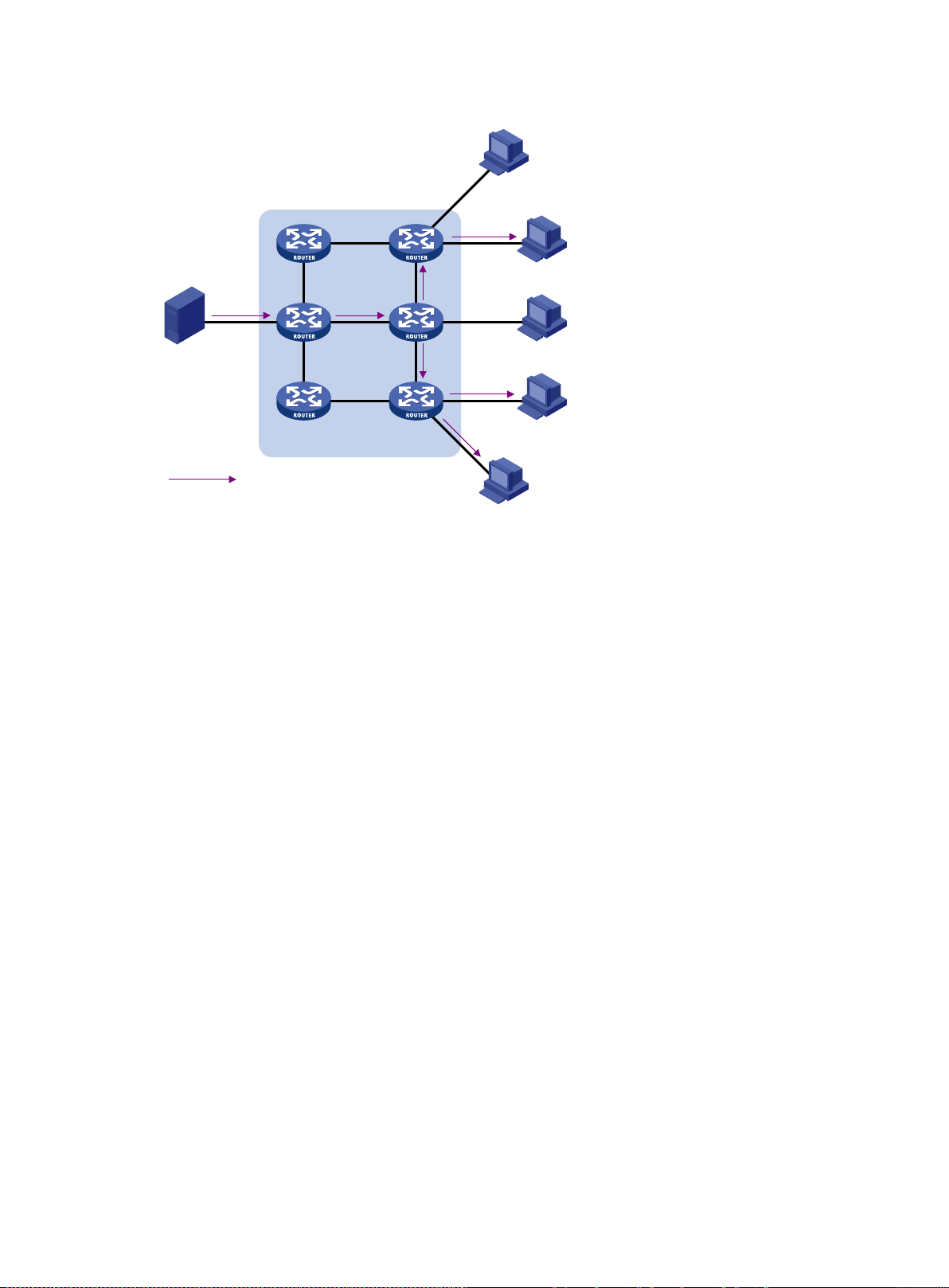
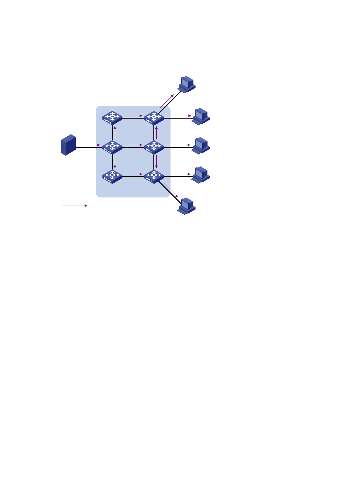
Figure 3 Multicast transmission
•
•
•
•
•
•
Source
Receiver
Receiver
Receiver
Host A
Host B
Host C
Host D
Host E
Packets for the multicast group
IP network
The multicast source s ends only one copy of the inf ormation to a m ulticast group. Host B, Hos t D,
and Host E, which are information receivers, must join the multicast group. The routers on the
network duplicate and forward the information based on the distribution of the group members.
Finally, the information is correctly delivered to Host B, Host D, and Host E.
To summarize, multicast has the following advantages:
Advantages over unicast—Multicast data is replicated and distributed until it flows to the
farthest-possible node from the source. The increase of receiver hosts will not remarkably
increase the load of the source or the usage of network resources.
Advantages over broadcast—Multicast data is sent only to the receivers that need it. This
saves network bandwidth and enhances network security. In addition, multicast data is not
confined to the same subnet.
Multicast features
A multicast group is a multicast receiver set identified by an IP multicast address. Hosts must
join a multicast group to become members of the multicast group before they receive the
multicast data addressed to that multicast group. Typically, a multicast source does not need to
join a multicast group.
A multicast source is an information sender. It can send data to multiple multicast groups at the
same time. Multiple multicast sources can send data to the same multicast group at the same
time.
The group memberships are dynamic. Hosts can join or leave multicast groups at any time.
Multicast groups are not subject to geographic restrictions.
Multicast routers or Layer 3 multicast devices are routers or Layer 3 switches that support Layer
3 multicast. They provide multicast routing and manage multicast group memberships on stub
subnets with attached grou p members. A multicast router itself can be a multicast group
member.
For a better understandi ng of the m ulticas t c onc ep t, you can compare multic ast tr ans mission to the
transmission of TV programs.
3
Page 14

Table 1 Comparing TV program transmission and multicast transmissio n
TV program transmission
Multicast transmission
•
•
•
•
•
•
•
•
•
A TV station transmits a TV program through a
channel.
A user tunes the TV set to the channel. A receiver joins the multicast group.
The user starts to watch the TV program
transmitted by the TV station on the channel.
The user turns off the TV set or tunes to another
channel.
A multicast source sends multicast data to a multicast
group.
The receiver starts to receive the multicast data sent by
the source to the multicast group.
The receiver leaves the multicast group or joins another
group.
Common notations in m ulticast
The following notations are commonly used in multicast transmission:
(*, G)—Rendezvous point tree (RPT), or a multicast packet that any multicast source sends to
multicast group G. The asterisk (*) represents any multicast source, and "G" represents a
specific multicast group.
(S, G)—Shortest path tree (SPT), or a multicast packet that multicast source "S" sends to
multicast group "G." "S" represents a specific multicast source, and "G" represents a specific
multicast group.
For more inf ormation about the c oncepts RPT and SPT, see "Configuring PIM" and "Configuring
IPv6 PIM."
Multicast benefits and applications
Multicast benefits
Enhanced efficiency—Reduces the processor load of information source servers and network
devices.
Optimal performance—Reduces redundant traffic.
Distributed application—Enables point-to-multipoint applications at the price of minimum
network resources.
Multicast applications
Multimedia and streaming applications, such as Web TV, Web radio, and real-time video/audio
conferencing
Communication for training and cooperative operations, such as distance learning and
telemedicine
Data warehouse and financial applications (stock quotes)
Any other point-to-multipoint application for data distribution
Multicast models
Based on how th e receivers treat th e multicast sources, the multicast m odels include any-source
multicast (ASM), source-filtered multicast (SFM), and source-specific multicast (SSM).
ASM model
In the ASM model, any multicast sources can send infor mation to a multicast gr o up. R eceivers can
join a multicast group and get multicast inform ation addressed to that multicast group from any
4
Page 15

multicast sources. In this m odel, receivers do not know the positions of the multicast sources in
•
•
•
•
•
•
•
•
•
Address block
Description
maintenance, and so on. Table 3 lists com mon per mane nt
advance.
SFM model
The SFM model is deri ved from the ASM model. To a multicast source, the two models appear to
have the same multicast membership architecture.
The SFM model func tionall y extends t he ASM model. The upper-layer software c hecks the source
address of received multicast pack ets and perm its or d enies m ulticast t raffic from specific sources.
The receivers obtain the multicast data from only part of the multicast sources. To a receiver,
multicast sources are not all valid, but are filtered.
SSM model
The SSM model provides a transmission service that enables multicast receivers to specify the
multicast sources in which t he y are interes ted.
In the SSM model, receivers have already determined the locations of the multicast sources. This is
the main difference between the SSM model and the ASM model. In addition, the SSM model uses a
different multicast address r ange than the ASM/SFM model. Dedic ated multicast forwarding paths
are established between receivers and the specified multicast sources.
Multicast architecture
IP multicast addresses the following issues:
Where should the multicast source transmit information to? (Multicast addressing.)
What receivers exist on the network? (Host registration.)
Where is the multicast source that will provide data to the receivers? (Multicast source
discovery.)
How is the information transmitted to the receivers? (Multicast routing.)
IP multicast is an end-to-end service. The multicast architecture involves the following parts:
Addressing mechanism—A multicast source sends information to a group of receivers
through a multicast address.
Host registration—Receiver hosts can join and leave multicast groups dynamically. This
mechanism is the basis for management of group memberships.
Multicast routing—A multicast distribution tree (a forwarding path tree for multicast data on the
network) is constructed for delivering multicast data from a multicast source to receivers.
Multicast applications—A software system that supports multicast applications, such as video
conferencing, must be installed on multicast sources and receiver hosts. The TCP/IP stack
must support reception and transmission of multicast data.
Multicast addresses
IP multicast addresses
IPv4 multicast addresses:
IANA assigned the Class D address block (224.0.0.0 to 239.255.255.255) to IPv4 multicast.
Table 2 Class D IP address blocks and description
224.0.0.0 to 224.0.0.255
Reserved permanent group addresses. The IP address
224.0.0.0 is reserved. Other IP addre sses can be use d by
routing protocols and for topology searching, protocol
5
Page 16

Address block
Description
group addresses. A packet destined for an address in this
block will not be forw arded b eyond the l ocal subnet r egard les s
224.0.1.0 to 238.255.255.255
NOTE:
Glop is a mechanism for assigning multicast addresses between different ASs. By filling an AS
number into the middle two bytes of 233.0.0.0, you get 255 multicast addresses for that AS. For
more information, see RFC 2770.
Address
Description
•
239.0.0.0 to 239.255.255.255
of the TTL value in the IP header.
Globally scoped group addresses. This block includes the
following types of designated group addresses:
• 232.0.0.0/8—SSM group addresses.
• 233.0.0.0/8—Glop group addr esses.
Administratively scoped multicast addresses. These
addresses are considered locally unique rather than global ly
unique. You can reuse them in domains administered by
different organizations without causing conflicts. For more
information, see RFC 2365.
Table 3 Common permanent multicast group addresses
224.0.0.1 All systems on this subnet, including hosts and routers.
224.0.0.2 All multicast routers on this subnet.
224.0.0.3 Unassigned.
224.0.0.4 DVMRP routers.
224.0.0.5 OSPF routers.
224.0.0.6 OSPF designated routers and backup designated routers.
224.0.0.7 Shared Tree (ST) routers.
224.0.0.8 ST hosts.
224.0.0.9 RIPv2 routers.
224.0.0.11 Mobile agents.
224.0.0.12 DHCP server/relay agent.
224.0.0.13 All Protocol Independent Multicast (PIM) routers.
224.0.0.14 RSVP encapsulation.
224.0.0.15 All Core-Based Tree (CBT) routers.
224.0.0.16 Designated SBM.
224.0.0.17 All SBMs.
224.0.0.18 VRRP.
IPv6 multicast addresses:
6
Page 17

Figure 4 IPv6 multicast format
Bit
Description
Value
Meaning
Group ID (112 bits)
0xFF
Flags
Scope
0 7 11 15 31
0
R
P
T
The following describes the fields of an IPv6 multicast address:
0xFF—The most significant eight bits are 11111111.
Flags—The Flags field contains four bits.
Figure 5 Flags field format
Table 4 Flags field description
0 Reserved, set to 0.
• When set to 0, this address is an IPv6 multicast
address without an embedded RP address.
R
• When set to 1, this address is an IPv6 multicast
address with an embedded RP address. (The P and T
bits must also be set to 1.)
• When set to 0, this address is an IPv6 multicast
address not based on a unicast prefix.
P
• When set to 1, this address is an IPv6 multicast
address based on a un icast p refix . (The T bit must a lso
be set to 1.)
• When set to 0, this address is an IPv6 multicast
T
address permanently-assigned by IANA.
• When set to 1, this address is a transient or
dynamically assigned IPv6 multicast address.
Scope—The Scope field contains four bits, which represent the scope of the IPv6
internetwork for which the multicast traffic is intended.
Table 5 Values of the Scope field
0, F Reserved.
1 Interface-local scope.
2 Link-local scope.
3 Subnet-local scope.
4 Admin-local scope.
5 Site-local scope.
6, 7, 9 through D Unassigned.
8 Organization-local scope.
E Global scope.
7
Page 18
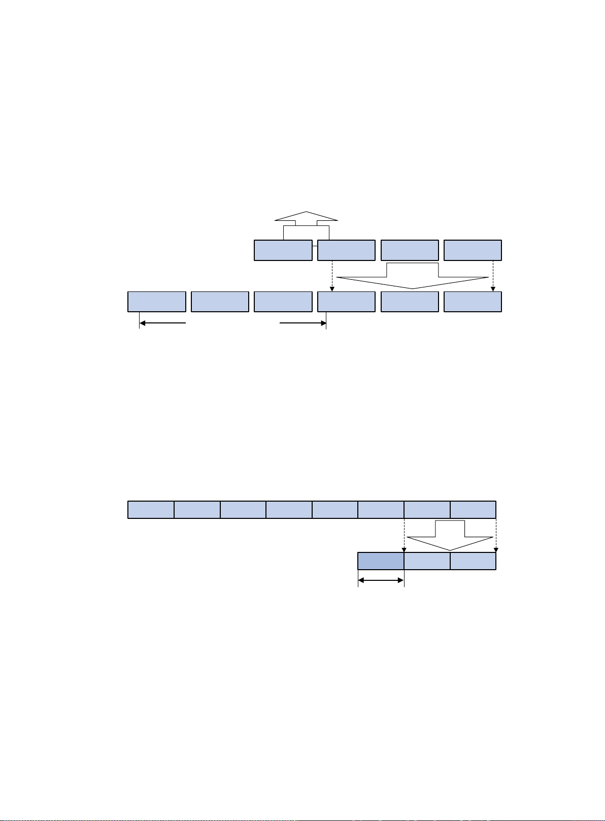
•
•
•
XXXX X
XXXX XXXX
XXXX XXXX
XXXX XXXX
1110 XXXX
0XXX XXXX
XXXX XXXX
XXXX XXXX
0000 0001
0000 0000
0101 1110
32-bit IPv4 address
48-bit MAC address
5 bits lost
25
-
bit MAC address prefix
…
23 bits
mapped
…
FF1E 0000 0000 0000 0000 0000 F30E 0101
0101aF30E
48-bit MAC address
3333
32 bits
mapped
128-bit IPv6 address
… …
16-bit MAC
address prefix
Group ID—The Group ID field contains 112 bits. It uniquely identifies an IPv6 multicast
group in the scope that the Scope field defines.
Ethernet multicast MAC addresses
IPv4 multicast MAC addresses:
As defined by IANA, the most significant 24 bits of an IPv4 multicast MAC address are
0x01005E. Bit 25 is 0, and the other 23 bits are the least significant 23 bits of an IPv4 multicast
address.
Table 6 IPv4-to-MAC address mapping
The most significant four bits of an IPv4 multicast address are fixed at 1110. In an IPv4-to-MAC
address mapping, five bits of the IPv4 multicast address are lost. As a result, 32 IPv4 multicast
addresses are mapped to the same IPv4 multicast MAC address. A device might rec eive
unwanted multicast data at Layer 2 processing, which needs to be filtered by the upper layer.
IPv6 multicast MAC addresses:
As defined by IANA, the most significant 16 bits of an IPv6 multicast MAC address are 0x3333.
The least significant 32 bits are mapped from the least significant 32 bits of an IPv6 multicast
address. Therefore, the problem of duplicate IPv6-to-MAC address mapping also arises like
IPv4-to-MAC address mapping.
Table 7 IPv6-to-MAC address mapping
Multicast protoc ol s
Multicast protocols include the following categories:
Layer 3 and Layer 2 multicast protocols:
Layer 3 multicast refers to IP multicast operating at the network layer.
Layer 2 multicast refers to IP multicast operating at the data link layer.
Layer 3 multicast protocols—IGMP, MLD, PIM, IPv6 PIM, MSDP, MBGP, and IPv6
MBGP.
8
Page 19
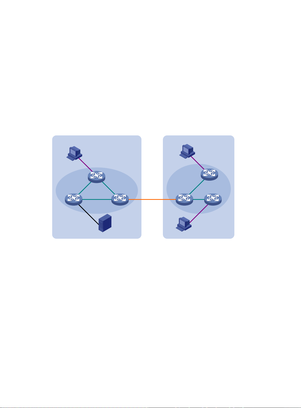
Layer 2 multicast protocols—IGMP snooping, MLD snooping, PIM snooping, IPv6 PIM
•
•
•
AS 1 AS 2
Source
Receiver
Receiver
Receiver
PIM/IPv6 PIM
PIM/IPv6 PIM
MBGP/MSDP
IPv6 MBGP
IGMP/MLD
IGMP/MLD
IGMP
/MLD
snooping, multicast VLAN, and IPv6 multicast VLAN.
IPv4 and IPv6 multicast protocols:
For IPv4 networks—IGMP snooping, PIM snooping, multicast VLAN, IGMP, PIM, MSDP,
and MBGP.
For IPv6 networks—MLD snooping, IPv6 PIM snooping, IPv6 multicast VLAN, MLD, IPv6
PIM, and IPv6 MBGP.
This section provides o nly general descriptions a bout applications and f unc t ions of the Layer 2 and
Layer 3 multicast protocols in a network. For more information about these protocols, see the related
chapters.
Layer 3 multicast protocols
Layer 3 multicast pro tocols include multicast group managem ent protocols and multicast routing
protocols.
Figure 6 Positions of Layer 3 multicast protocols
Multicast group management protocols:
Multicast routing protocols:
Internet Group Management Protocol (IGMP) and Multicast Listener Discovery (MLD) protocol
are multicast group management protocols. Typically, they run between hosts and Layer 3
multicast devices that directly connect to the hosts to establish and maintain multicast group
memberships.
A multicast routing protocol runs on Layer 3 multicast devices to establish and maintain
multicast routes and correctly and efficiently forward multicast packets. Multicast routes
constitute loop-free data transmission paths (also known as multicast distribution trees) from a
data source to multiple receivers.
In the ASM model, multicast routes include intra-domain routes and inter-domain routes.
An intra-domain multicast routing protocol discovers multicast sources and builds multicast
distribution trees within an AS to deliver multicast data to receivers. Among a variety of
mature intra-domain multicast routing protocols, PIM is most widely used. Based on the
forwarding mechanism, PIM has dense mode (often referred to as PIM-DM) and sparse
mode (often referred to as PIM-SM).
An inter-domain multicast routing protocol is used for delivering multicast information
between two ASs. So far, mature solutions include Multicast Source Discovery Protocol
(MSDP) and MBGP. MSDP propagates multicast source information among different ASs.
9
Page 20
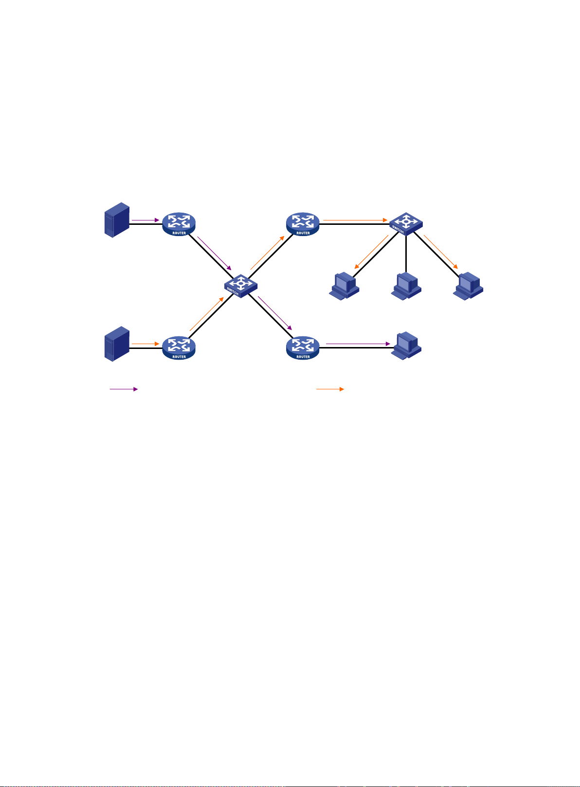
MBGP is an extension of the MP-BGP for exchanging multicast routing information among
•
•
•
IPv4/
IPv6 multicast packets (S1, G1)
IPv4/IPv6 multicast packets (S2, G2)
Source 1
Source 2
Receiver
IGMP Snooping
/MLD Snooping
Receiver Receiver
Multicast VLAN
/IPv6 Multicast VLAN
PIM Snooping
/
IPv6 PIM Snooping
different ASs.
For the SSM model, multicast routes are not divided into intra-domain routes and inter-domain
routes. Because receivers know the positions of the multicast sources, channels established
through PIM-SM are sufficient for the transpor t of multicast information.
Layer 2 multicast protocols
Layer 2 multicast protocols include IGMP snooping, MLD snooping, PIM snooping, IPv6 PIM
snooping, multicast VLAN, and IPv6 multicast VLAN.
Figure 7 Positions of Layer 2 multicast pro to cols
IGMP snooping and MLD snooping:
IGMP snooping and MLD snooping are multicast constraining mechanisms that run on Layer 2
devices. They manage and control multicast groups by monitoring and analyzing IGMP or MLD
messages exchanged between the hosts and Layer 3 multicast devices. This effectively
controls the flooding of multicast data in Layer 2 networks.
PIM snooping and IPv6 PIM snooping:
PIM snooping and IPv6 PIM snooping run on Layer 2 devices. They work with IGMP snooping
or MLD snooping to analyze received PIM messages. Then, they add the ports that are
interested in specific multicast data to a PIM snooping routing entry or IPv6 PIM snooping
routing entry. In this way, multicast data can be forwarded to only the ports that are interested in
the data.
Multicast VLAN and IPv6 multicast VLAN:
Multicast VLAN or IPv6 multicast VLAN runs on a Layer 2 device in a multicast network where
multicast receivers for the same group exist in different VLANs. With these protocols, the Layer
3 multicast device sends only one copy of multicast to the multicast VLAN or IPv6 multicast
VLAN on the Layer 2 device. This method avoids waste of network bandwidth and extra burden
on the Layer 3 device.
Multicast packet forwarding mechanism
In a multicast model, receiver hosts of a multicast group are usually located at different areas on the
network. They are ide ntified by the same m ulticast group address . To deliver multicast packets to
these receivers, a multicast source encapsulates the multicast data in an IP packet with the multicast
group address as the destination address. Multicast routers on the forwarding paths forward
10
Page 21
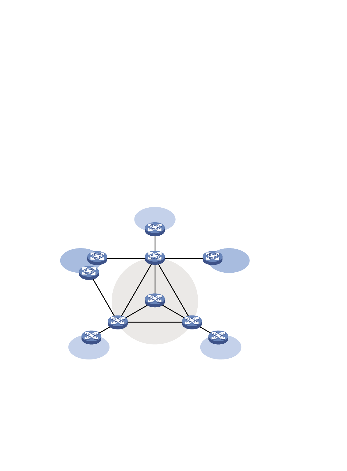
multicast packets that an incoming interface receives through multiple outgoing interfaces.
•
•
•
•
VPN A
VPN A
VPN A
VPN BVPN B
Public network
P
PE 1
PE
2
PE 3
CE b3
CE a2
CE a3
CE b
1
CE a
1
CE b2
Compared to a unicast model, a multicast model is more complex in the following aspects:
To ensure multicast packet transmission on the network, different routing tables are used to
guide multicast forwarding. These routing tables include unicast routing tables, routing tables
for multicast (for example, the MBGP routing table), and static multicast routing tables.
T o process the same multicast information from different peers received on different interfaces,
the multicast device performs an RPF check on each multicast packet. The RPF check result
determines whether the packet will be forwarded or discarded. The RPF check mechanism is
the basis for most multicast routing protocols to implement multicast forwarding.
For more information about the RPF mechanism, see "Configuring multicast routing and
forwarding" and "Configuring IPv6 multicast routing and forwarding."
Multicast support for VPNs
Multicast support for VPNs refers to multicast applied in VPNs.
Introduction to VPN instances
VPNs are isolated from one another and from the public network. As shown in Figure 8, VPN A and
VPN B separately access the public network through PE devices.
Figure 8 VPN networking diagram
The P device belongs to the public network. The CE devices belong to their respective VPNs.
Each CE device serves its own VPN and maintains only one set of forwarding mechanisms.
The PE devices connect to the public network and the VPNs. Each PE device must strictly
distinguish the information for different networks, and maintain a separate forwarding
mechanism for each network. On a PE device, a set of software and hardware that serve the
same network forms an instance. Multiple instances can exist on the same PE device, and an
instance can reside on different PE devices. On a PE device, the instance for the public network
is called the public network instance, and those for VPNs are called VPN instances.
11
Page 22

Multicast application in VPNs
•
•
•
A PE device that supports multicast for VPNs does the following operations:
Maintains an independent set of multicast forwarding mechanisms for each VPN, including the
multicast protocols, PIM neighbor information, and multicast routing table. In a VPN, the device
forwards multicast data based on the forwarding table or routing table for that VPN.
Implements the isolation between different VPNs.
Implements information exchange and data conversion between the public network and VPN
instances.
For example, as shown in Figure 8, a multicast source in VPN A sends multicast data to a multicast
group. Only receivers t hat belong t o both t he multicas t group and VPN A can receive the m ulticast
data. The multicast data is multicast both in VPN A and on the public network.
12
Page 23
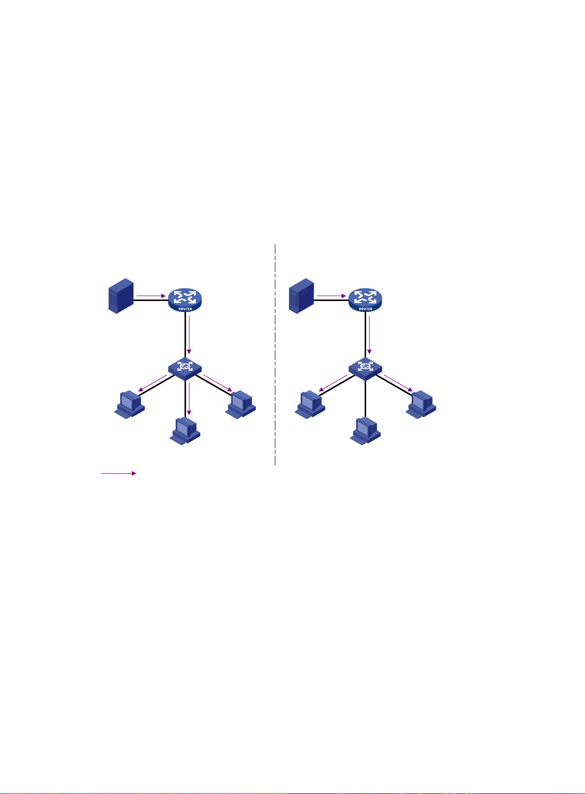
Configuring IGMP snooping
Multicast packet transmission
without IGMP snooping
Source
Multicast router
Host A
Receiver
Host B
Host C
Receiver
Multicast packets
Layer 2
switch
Multicast packet transmission
when IGMP
snooping runs
Source
Multicast router
Host A
Receiver
Host B
Host C
Receiver
Layer 2 switch
Overview
IGMP snooping runs on a Layer 2 device as a multicast constraining mechanism to improve
multicast forwarding efficiency. It creates La yer 2 multicast forwarding e ntries from IGMP packets
that are exchanged between the hosts and the router.
As shown in Figure 9, when IGMP snooping is not enabled, the Layer 2 switch floods multicast
packets to all hosts in a VLAN or VSI. When IGMP snooping is enabled, the Layer 2 switch forwards
multicast packets of known multicast groups to only the receivers.
Figure 9 Multicast packet transmission without and with IGMP snooping
IGMP snooping ports
As shown in Figure 10, IGMP snooping runs on Switch A and Switch B, and Host A and Host C are
receivers in a multicast group. IGMP snooping ports are divided into member ports and router ports.
13
Page 24
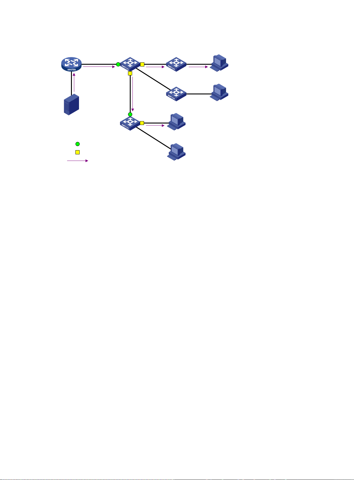
Figure 10 IGMP snooping ports
•
•
•
•
Router A Switch A
Switch B
GE1/0/1 GE1/0/2
GE1/0/3
GE
1/
0/
1
GE1
/0/2
Receiver
Receiver
Host A
Host B
Host C
Host D
Source
Multicast packets
Router port
Member port
Router ports
On an IGMP snooping La yer 2 d evice, t he por ts to ward La yer 3 m ulticast d evices are c alled r outer
ports. In Figure 10, GigabitEth ernet 1/0/1 of Switch A and GigabitEthernet 1/0/1 of Switc h B are
router ports.
Router ports contain the following types:
Dynamic router port—When a port receives an IGMP general query whose source address is
not 0.0.0.0 or receives a PIM hello message, the port is added into the dynamic router port list.
At the same time, an aging timer is started for the port. If the port receives either of the
messages before the timer expires, the timer is reset. If the port does not receive either of the
messages when the timer expires, the port is removed from the dynamic router port list.
Static router port—When a port is statically configured as a router port, it is added into the
static router port list. The static router port does not age out, and it can be deleted only
manually.
Do not confuse th e "router port" i n IGMP snoop ing wit h the "rout ed inter face" co mmonl y known as
the "Layer 3 interface." The router port in IGMP snooping is a Layer 2 interface.
Member ports
On an IGMP snooping Layer 2 device, the ports tow ard rece iver h osts are c alled m em ber ports . In
Figure 10, GigabitEthernet 1/0/2 and GigabitEthernet 1/0/3 of Switch A and GigabitEthernet 1/0/2 of
Switch B are member ports.
Member ports contain the following types:
Dynamic member port—When a port receives an IGMP report, it is added to the associated
dynamic IGMP snooping forwarding entry as an outgoing interface. At the same time, an aging
timer is started for the port. If the port receives an IGMP report before the timer expires, the
timer is reset. If the port does not receive an IGMP report when the timer expires, the port is
removed from the associated dynamic forwarding entry.
Static member port—When a port is statically configured as a member port, it is added to the
associated static IGMP snooping forwarding entry as an outgoing interface. The static member
port does not age out, and it can be deleted only manually.
Unless otherwise spec if ied, router ports and member ports in this document include both static and
dynamic router ports and member ports.
14
Page 25

How IGMP snooping works
•
•
•
•
•
•
•
The ports in this section are dynamic ports. For information about how to configure and remove static
ports, see "Configuring static ports."
IGMP messages types include general query, IGMP report, and leave message. An IGMP
snooping-enabled Layer 2 device performs differently depending on the message types.
General query
The IG MP querier periodically sends IGM P general queries to all hosts and routers on th e local
subnet to check for the existence of multicast group members.
After receiving an IGMP general query , the Layer 2 device forwards the query to all ports in the VLAN
or VSI except the receiving port. The Layer 2 device also performs one of the following actions:
If the receiving port is a dynamic router port in the dynamic router port list, the Layer 2 device
restarts the aging timer for the port.
If the receiving port does not exist in the dynamic router port list, the Layer 2 device adds the
port to the dynamic router port list. It also starts an aging timer for the port.
IGMP report
A host sends an IGMP report to the IGMP querier for the following purposes:
Responds to queries if the host is a multicast group member.
Applies for a multicast group membership.
After receiving an IGM P report from a host, the L ayer 2 device forw ards the report throu gh all the
router ports in the VL AN or VSI. It also resol ves the address of the r eported multicast gr oup, and
looks up the forwarding table for a matching entry as follows:
If no match is found, the Layer 2 device creates a forwarding entry with the receiving port as an
outgoing interface. It also marks the receiving port as a dynamic member port and starts an
aging timer for the port.
If a match is found but the matching forwarding entry does not contain the receiving port, the
Layer 2 device adds the receiving port to the outgoing interface list. It also marks the receiving
port as a dynamic member port and starts an aging timer for the port.
If a match is found and the matching forwarding entry contains the receiving port, the Layer 2
device restarts the aging timer for the port.
In an application with a group policy configured on an IGMP snooping-enabled Layer 2 device, when
a user requests a m ulticast program, the us er's host initiates an IG MP report. After receiving this
report, the Layer 2 device resolves the multicast group address in the rep ort and performs ACL
filtering on the report. If the report passes ACL filtering, the Layer 2 device creates an IGMP
snooping forwarding entry for the multicast group with the receiving port as an outgoing interface. If
the report does not pass ACL filtering, the Layer 2 device drops this report. The multicast data for the
multicast group is not sent to this port, and the user cannot re trie ve the progr am.
A Layer 2 device does not forward an IGMP report thr ough a non-router p ort because of the host
IGMP report suppression mechanism. For more information about the IGMP report suppression
mechanism, see "Configuring IGMP."
Leave message
An IGMPv1 receiver host does not send any leave messages when it leaves a multicast group. The
Layer 2 device cannot imm ediate ly update the s tatus of the por t that conn ects to the rec eiver host.
The Layer 2 device does not remove the port from the outgoing interface list in the associated
forwarding entry until the aging time for the group expires.
An IGMPv2 or IGMPv3 host sends an IGMP leave message when it leaves a multicast group.
When the Layer 2 device receives an IGMP leave message on a dynamic member port, the Layer 2
device first examines whether a forwarding entry matches the group address in the message.
15
Page 26
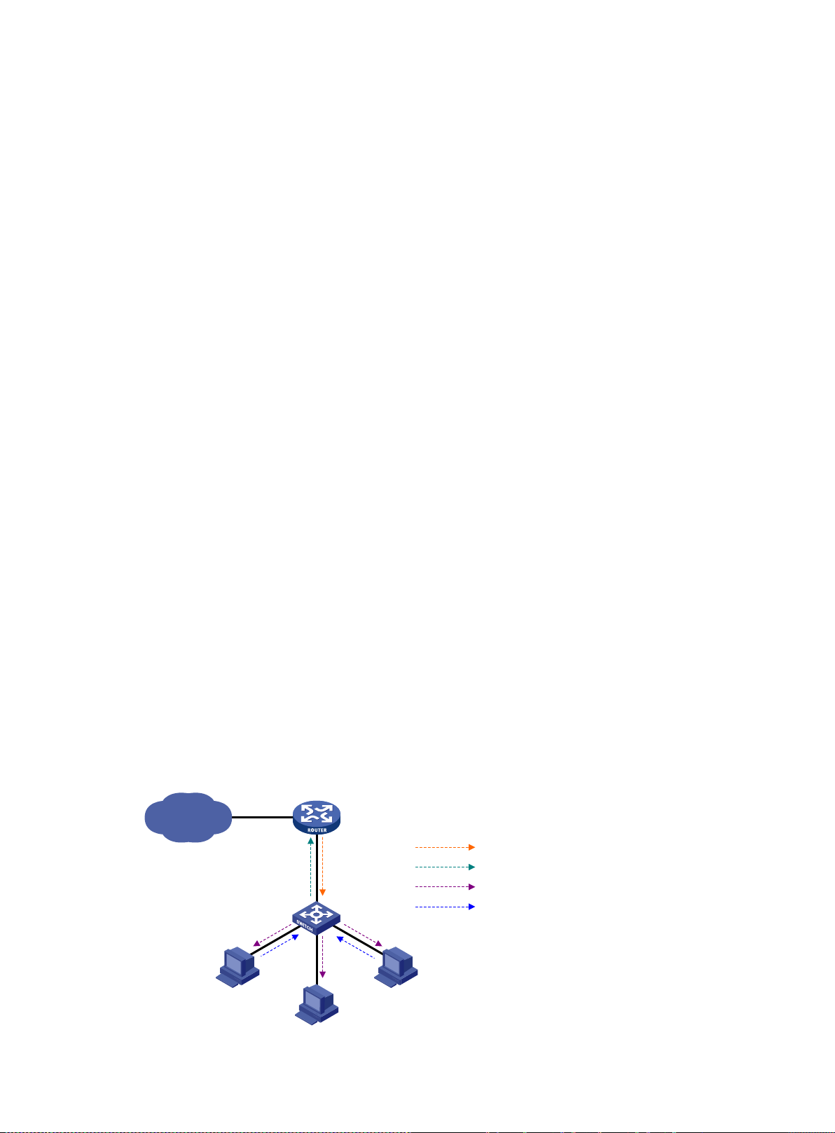
•
•
•
•
•
•
Host A
Receiver
Host B
Host C
Receiver
IGMP Querier
Router A
Proxy
Switch A
Query from Router A
Report from Switch A
Query from Switch A
Report from Host
IP network
If no match is found, the Layer 2 device discards the IGMP leave message.
If a match is found but the receiving port is not an outgoing interface in the forwarding entry , the
Layer 2 device discards the IGMP leave message.
If a match is found and the receiving port is not the only outgoing interface in the forwarding
entry, the Layer 2 device performs the following actions:
Discards the IGMP leave message.
Sends an IGMP group-specific query to identify whether the group has active receivers
attached to the receiving port.
Sets the aging timer for the receiving port to twice the IGMP last member query interval.
If a match is found and the receiving port is the only outgoing interface in the forwarding entry,
the Layer 2 device performs the following actions:
Forwards the IGMP leave message to all router ports in the VLAN or VSI.
Sends an IGMP group-specific query to identify whether the group has active receivers
attached to the receiving port.
Sets the aging timer for the receiving port to twice the IGMP last member query interval.
After receiving the IGMP leave mes sage on a port, the IGMP querier resol ves the multicast group
address in the message. Then, it sends an IGMP group-specific query to the multicast group through
the receiving port.
After receiving the IGM P group-specific query, the Layer 2 device f orwards the query through all
router ports and mem ber ports of the group in the VLAN or V SI. Then, it waits for the respon ding
IGMP report from the directly connected hosts. For the dynamic member port that received the leave
message, the Layer 2 device also performs one of the following actions:
If the port receives an IGMP report before the aging timer expires, the Layer 2 device resets the
aging timer.
If the port does not receive an IGMP report when the aging timer expires, the Layer 2 device
removes the port from the forwarding entry for the multicast group.
IGMP snooping proxying
As shown in Figure 11, to reduce the number of IGMP reports and leave messages received by the
upstream device, you can enable IGM P snooping prox ying on the edge device . The edge device
then acts as a host to send IGMP reports and leave messages to Router A.
An edge device enabled with IGMP snooping proxying does not support the host IGMP report
suppression mechanism. For more information about the IGMP report suppression mechanism, see
"Configuring IGMP."
Figure 11 IGMP snooping proxying
16
Page 27

•
•
•
•
•
•
•
The IGMP snooping proxy device processes different IGMP messages as follows:
General query.
After receiving an IGMP general query, the device forwards the query to all ports in the VLAN
except the receiving port. The device also generates an IGMP report based on the local
membership information and sends the report to all router ports.
Group-specific query or group-and-source-specific query.
After receiving an IGMP group-specific query or group-and-source-specific query, the device
forwards the query to all router ports in the VLAN except the receiving port. If the forwarding
entry has a member port, the device sends a report to all router ports in the VLAN.
Report.
After receiving an IGMP report from a host, the devic e looks up the forwarding table for a
matching entry as follows:
If a match is found and the matching forwarding entry contains the receiving port, the device
resets the aging timer for the port.
If a match is found but the matching forwarding entry does not contain the receiving port, the
device adds the receiving port to the outg oin g interface list. It also marks the receiving port
as a dynamic member port and starts an aging timer for the port.
If no match is found, the device creates a forwarding entry with the receiving port as an
outgoing interface. It also marks the receiving port as a dynamic member port and starts an
aging timer for the port. Then it sends the report to all router ports.
Leave message.
After receiving an IGMP leave message on a port, the device sends an IGMP group-specific
query through the receiving port. The device sends the IGMP leave message to all router ports
only when the last member port is removed from the forwarding entry.
Protocols and standards
RFC 4541, Considerat ions for Internet G ro up Man agement Protoc ol ( IG MP) and Multicast Lis tener
Discovery (MLD) Snooping Switches
Configuration restrictions and guidelines
When you configure IGMP snooping, follow these restrictions and guidelines:
If you change the VPN instance bound to the VLAN interface of a VLAN, Layer 2 multicast traffic
in the VLAN is interrupted. To allow new IGMP snooping forwarding entries to be created,
execute the reset igmp-snooping group command.
For IGMP reports received from secondary VLANs, the relevant IGMP snooping forwarding
entries are maintained by the primary VLAN. Therefore, you need to enable IGMP snooping
only for the primary VLAN. The IGMP snooping configuration made in secondary VLANs does
not take effect. For more information about primary VLANs and secondary VLANs, see Layer
2—LAN Switching Configuration Guide.
The IGMP snooping configurations made on Layer 2 aggregate interfaces do not interfere with
the configurations made on member ports. In addition, the configurations made on Layer 2
aggregate interfaces do not take part in aggregation calculations. The configuration made on a
member port of the aggregate group takes effect after the port leaves the aggregate group.
IGMP snooping configuration task list
You can configure IGMP snooping for VLANs or VSIs.
17
Page 28

IGMP snooping configuration t as k list for VLANs
Tasks at a glance
Tasks at a glance
Configuring basic IGMP snooping features:
• (Required.) Enabling IGMP snooping
• (Optional.) Specifying an IGMP snooping version
• (Optional.) Setting the maximum number of IGMP snooping forwarding entries
• (Optional.) Configuring static multicast MAC address entries
• (Optional.) Setting the IGMP last member query interval
Configuring IGMP snooping port features:
• (Optional.) Setting aging timers for dynamic ports
• (Optional.) Configuring static ports
• (Optional.) Configuring a port as a simulated member host
• (Optional.) Enabling fast-leave processing
• (Optional.) Disabling a port from becoming a dynamic router port
Configuring the IGMP snooping querier:
• (Optional.) Enabling the IGMP snooping querier
• (Optional.) Configuring parameters for IGMP general queries and responses
(Optional.) Enabling IGMP snooping proxying
Configuring parameters for IGMP messages:
• (Optional.) Configuring the source IP address for IGMP messages
• (Optional.) Setting the 802.1p priority for IGMP messages
Configuring IGMP snooping policies:
• (Optional.) Configuring a multi cast group policy
• (Optional.) Enabling multicast source port filtering
• (Optional.) Enabling dropp ing unknown multicast data
• (Optional.) Enabling IGMP report suppression
• (Optional.) Setting the maximum number of multicast groups on a port
• (Optional.) Enabling mul tic ast group r epl ace men t
• (Optional.) Enabling host tracking
IGMP configuration task list for VSIs
Configuring basic IGMP snooping features:
• (Required.) Enabling IGMP snooping
• (Optional.) Specifying an IGMP snooping version
• (Optional.) Setting the maximum number of IGMP snooping forwarding entries
• (Optional.) Setting the IGMP last member query interval
Configuring IGMP snooping port features:
• (Optional.) Setting aging timers for dynamic ports
Configuring the IGMP snooping querier:
• (Optional.) Enabling the IGMP snooping querier
• (Optional.) Configuring parameters for IGMP general queries and responses
Configuring parameters for IGMP messages:
• (Optional.) Configuring the source IP address for IGMP messages
18
Page 29

Tasks at a glance
• (Optional.) Setting the 802.1p priority for IGMP messages
Configuring IGMP snooping policies:
•
•
•
•
•
•
•
Step
Command
Remarks
Step
Command
Remarks
5.
By default, IGMP snooping is
• (Optional.) Enabling dropp ing unknown multicast data
• (Optional.) Enabling mul tic ast group r epl ace men t
Configuring basic IGMP snooping features
Before you configure basic IGMP snooping features, complete the following tasks:
Configure VLANs or VSIs.
Determine the IGMP snooping version.
Determine the maximum number of IGMP snooping forwarding entries.
Determine the IGMP last member query interval.
Enabling IGMP s nooping
When you enable IGMP snooping, follow these restrictions and guidelines:
You must enable IGMP snooping globally before you enable it for a VLAN or VSI.
IGMP snooping configuration made in VLAN or VSI view takes effect only on the member ports
in that VLAN or VSI.
You can enable IGMP snooping for the specified VLANs in IGMP-snoopi ng vi e w, for a VSI in
VSI view, or for a VLAN in VLAN view. For a VLAN, the configuration in VLAN view has the
same priority as the configuration in IGMP-snooping view, and the most recent configuration
takes effect.
Enabling IGMP snooping in IGMP-snooping view
1. Enter system view.
2. Enable IGMP snooping
globally and enter
IGMP-snooping view.
3. Enable IGMP snooping for
the specified VLANs.
system-view
igmp-snooping
enable vlan
vlan-list
Enabling IGMP snooping in VLAN or VSI view
1. Enter system view.
2. Enable IGMP snooping
globally and enter
IGMP-snooping view.
3. Return to system view.
4. Enter VLAN view or VSI
view.
system-view
igmp-snooping
quit
• Enter VLAN view:
vlan vlan-id
• Enter VSI view:
vsi vsi-name
N/A
By default, IGMP snooping is
globally disabled.
By default, IGMP snooping is
disabled for a VLAN.
N/A
By default, IGMP snooping is
globally disabled.
N/A
N/A
Enable IGMP snooping for
igmp-snooping enable
19
Page 30

Step
Command
Remarks
the VLAN or VSI.
disabled in a VLAN or VSI.
•
•
•
•
•
Step
Command
Remarks
Step
Command
Remarks
Specifying an IGMP snooping version
Different IGMP snooping versions process different versions of IGMP messages.
IGMPv2 snooping processes IGMPv1 and IGMPv2 messages, but it floods IGMPv3 messages
in the VLAN instead of processing them.
IGMPv3 snooping processes IGMPv1, IGMPv2, and IGMPv3 messages.
If you change IGMPv3 snooping to IGMPv2 snooping, the device performs the following actions:
Clears all IGMP snooping forwarding entries that are dynamicall y added.
Keeps static IGMPv3 snooping forwarding entries (*, G).
Clears static IGMPv3 snooping forwarding entries (S, G), which will be restored when IGMP
snooping is switched back to IGMPv3 snooping.
For more information about static IGMP snooping forwarding entries, see "Configuring static ports."
Y ou can specify the version for the specified VLANs in IGMP-snooping view, for a VSI in VSI view, or
for a VLAN in VLAN v ie w. For a VLAN, the c onf igura ti on i n V LA N v ie w has t he same priority as the
configuration in IGMP-snooping view, and the most recent configuration takes effect.
Specifying an IGMP snooping version in IGMP-snooping view
1. Enter system view.
2. Enable IGMP snooping
globally and enter
IGMP-snooping view.
3. Specify an IGMP snooping
version for the specified
VLANs.
system-view
igmp-snooping
version
vlan-list
version-number
vlan
N/A
N/A
The default setting is 2.
Specifying an IGMP snooping version in VLAN or VSI view
1. Enter system view.
2. Enter VLAN view or VSI view.
3. Specify an IGMP snooping
version for the VLAN or VSI.
system-view
• Enter VLAN view:
vlan vlan-id
• Enter VSI view:
vsi vsi-name
igmp-snooping version
version-number
N/A
N/A
The default setting is 2.
Setting the maximum number of IGMP s noopi ng forwarding entries
You can modify the maximum number of IGMP snooping forwarding entries, including dynamic
entries and static entr ies. W hen the number of forwardin g entries on the de vice reaches the upper
limit, the device does not automatically remove any existing entries. To allow new entries to be
created, remove some entries manually.
20
Page 31

To set the maximum number of IGMP snooping forwarding entries:
Step
Command
Remarks
system-view
igmp-snooping
•
•
•
Step
Command
Remarks
Step
Command
Remarks
1. Enter system view.
2. Enter IGMP-snooping view.
3. Set the maximum number of
IGMP snooping forwarding
entries.
entry-limit
limit
N/A
N/A
The default setting is
4294967295.
Configuring static multicast MAC address entries
In Layer 2 multicast, m ulticast MAC address entries can be dynamically created t hrough Layer 2
multicast protocols (such as IGMP snooping). Y ou can also manually configure static multicast MAC
address entries by binding multicast MAC addresses and ports to control the destination ports of the
multicast data.
Configuration restrictions and guidelines
When you configure static multicast MAC address entries, follow these restrictions and guidelines:
You do not need to enable IP multicast routing before this configuration.
Y ou must specify an unused multicast MAC address for a static multicast MAC address entry. A
multicast MAC address is a MAC address in which the least significant bit of the most significant
octet is 1.
Y ou can configure a static multicast MAC address entry for multiple interfaces in system view, or
for the current interface in interface view.
Configuring a static multicast MAC address entry in system view
1. Enter system view.
2. Configure a static multicast
MAC address entry.
system-view
mac-address multicast
mac-address
interface-list
interface
vlan
vlan-id
N/A
By default, no static multicast
MAC address entries exist.
Configuring a static multicast MAC address entry in interface view
1. Enter system view.
2. Enter Layer 2 Ethernet
interface or Layer 2
aggregate interface view.
3. Configure a static multicast
MAC address entry.
system-view
interface
interface-number
mac-address multicast
mac-address
interface-type
vlan
vlan-id
N/A
N/A
By default, no static multicast
MAC address entries exist.
Setting the IGMP las t member query interval
A receiver host starts a report delay timer for a multicast group when it receives an IGMP
group-specific query for the group. This timer is set to a random value in the range of 0 to the
maximum response tim e advertised in the query. When the timer value decreases to 0, the host
sends an IGMP report to the group.
21
Page 32

The IGMP last member query interval defines the maximum response time advertised in IGMP
•
•
Step
Command
Remarks
igmp-snooping
Step
Command
Remarks
•
•
•
•
•
•
group-specific queries. Set an ap propriate va lue for th e IGMP last m ember quer y interval to spe ed
up hosts' responses to IGMP group-specific queries and avoid IGMP report traffic bursts.
Configuration restrictions and guidelines
When you set the IGMP last member query interval, follow these restrictions and guidelines:
The Layer 2 device does not send an IGMP group-specific query if it receives an IGMP leave
message from a port enabled with fast-leave processing.
You can set the IGMP last member quer y interval glob ally for all VLANs and VSIs in
IGMP-snooping view, for a VSI in VSI view, or for a VLAN in VLAN view. For a VLAN, the
VLAN-specific configuration takes priority over the global configuration. For a VSI, the
VSI-specific configuration takes priority over the global configuration.
Setting the IGMP last member query interval globally
1. Enter system view.
2. Enter IGMP-snooping view.
3. Set the IGMP last member
query interval globally.
system-view
last-member-query-interval
interval
N/A
N/A
The default setting is 1
second.
Setting the IGMP last member query interval in a VLAN or VSI
1. Enter system view.
2. Enter VLAN view or VSI view.
3. Set the IGMP last member
query interval for the VLAN or
VSI.
system-view
• Enter VLAN view:
vlan vlan-id
• Enter VSI view:
vsi vsi-name
igmp-snooping
last-member-query-interval
interval
N/A
N/A
The default setting is 1
second.
Configuring IGMP snooping port features
Before you configure IGMP snooping port features, complete the following tasks:
Enable IGMP snooping for the VLAN or VSI.
Determine the aging timer for dynamic router ports.
Determine the aging timer for dynamic member ports.
Determine the addresses of the multicast group and multicast source.
Setting aging tim er s for dynamic port s
When you set aging timers for dynamic ports, follow these restrictions and guidelines:
If the memberships of multicast groups frequently change, you can set a relatively small value
for the aging timer of the dynamic member ports. If the memberships of multicast groups rarely
change, you can set a relatively large value.
If a dynamic router port receives a PIMv2 hello message, the aging timer for the port is specified
by the hello message. In this case, the router-aging-time or igmp-snooping
router-aging-time command does not take effect on the port.
22
Page 33

•
•
Step
Command
Remarks
system-view
Step
Command
Remarks
•
•
Step
Command
Remarks
2.
interface
interface-type
IGMP group-specific queries originated by the Layer 2 device trigger the adjustment of aging
timers for dynamic member ports. If a dynamic member port receives such a query, its aging
timer is set to twice the IGMP last member query interval. For more information about setting
the IGMP last member query interval on the Layer 2 device, see "
query interval."
You can set the timers globally for all VLANs and VSIs in IGMP-snooping view, for a VSI in VSI
view, or for a VLAN in VLAN view. For a VLAN, the VLAN-specific configuration takes priority
over the global configuration. For a VSI, the VSI-specific configuration takes priority over the
global configuration.
Setting the aging timers for dynamic ports globally
Setting the IGMP last member
1. Enter system view.
2. Enter IGMP-snooping view.
3. Set the aging timer for
dynamic router ports
globally.
4. Set the global aging timer for
dynamic member ports
globally.
igmp-snooping
router-aging-time
host-aging-time
seconds
seconds
Setting the aging timers for dynamic ports in a VLAN or VSI
1. Enter system view.
2. Enter VLAN view or VSI
view.
3. Set the aging timer for
dynamic router ports in the
VLAN or VSI.
4. Set the aging timer for
dynamic member por ts in t he
VLAN or VSI.
system-view
• Enter VLAN view:
vlan vlan-id
• Enter VSI view:
vsi vsi-name
igmp-snooping
router-aging-time
igmp-snooping host-aging-time
seconds
seconds
N/A
N/A
The default setting is 260
seconds.
The default setting is 260
seconds.
N/A
N/A
The default setting is 260
seconds.
The default setting is 260
seconds.
Configuring static ports
You can configure the following types of static ports:
Static member port—When you configure a port as a static member port for a multicast group,
all hosts attached to the port will receive multicast data for the group.
The static member port does not respond to IGMP queries. When you complete or cancel this
configuration on a port, the port does not send an unsolicited IGMP report or leave message.
Static router port—When you configure a port as a static router port for a multicast group, all
multicast data for the group received on the port will be forwarded.
To configure a port as a static port:
1. Enter system view.
Enter Layer 2 Ethernet
system-view
23
N/A
N/A
Page 34

Step
Command
Remarks
interface view or Layer 2
aggregate interface view.
interface-number
•
•
•
Step
Command
Remarks
•
•
• Configure the port as a static
member port:
igmp-snooping
static-group group-address
3. Configure the port as a static
port.
[ source-ip source-address ]
vlan vlan-id
• Configure the port as a static
router port:
igmp-snooping
static-router-port vlan
vlan-id
By default, a port is not a static
member port or a static router
port.
Configuring a port as a simulated member host
When a port is configured as a simulated member host, it is equivalent to an independent host in the
following wa ys:
It sends an unsolicited IGMP report when you complete the configuration.
It responds to IGMP general queries with IGMP reports.
It sends an IGMP leave message when you cancel the configuration.
The version of IGMP run ning on the simulated member host is the sam e as the version of IGMP
snooping running on the port. The port ages out in the same way as a dynamic member port.
To configure a port as a simulated member host:
1. Enter system view.
2. Enter Layer 2 Ethernet
interface view or Layer 2
aggregate interface view.
3. Configure the port as a
simulated member host.
system-view
interface
interface-number
igmp-snooping host-join
group-address [
source-address ]
interface-type
Enabling fast-leave processin g
This feature enables the device to immediately remove a port from the forwarding entry for a
multicast group when the port receives a leave massage.
Configuration restrictions and guidelines
When you enable fast-leave processing, follow these restrictions and guidelines:
Do not enable fast-leave processing on a port that has multiple receiver hosts in a VLAN. If
fast-leave processing is enabled, the remaining receivers cannot receive multicast data for a
group after a receiver leaves that group.
You can enable fast-lea ve proc ess ing globally for all ports in IGMP-snooping view or for a port
in interface view. For a port, the port-specific configuration takes priority over the global
configuration.
source-ip
vlan
vlan-id
N/A
N/A
By default, the port is not a
simulated member host.
24
Page 35

Enabling fast-leave processing globally
Step
Command
Remarks
Step
Command
Remarks
•
•
Step
Command
Remarks
1. Enter system view.
2. Enter IGMP-snooping view.
3. Enable fast-leave proces sing
globally.
system-view
igmp-snooping
fast-leave [ vlan
vlan-list ]
N/A
N/A
By default, fast-leave processing
is disabled globally.
Enabling fast-leave processing on a port
1. Enter system view.
2. Enter Layer 2 Ethernet
interface view or Layer 2
aggregate interface view.
3. Enable fast-leave proces sing
on the port.
system-view
interface
interface-number
igmp-snooping fast-leave [ vlan
vlan-list ]
interface-type
N/A
N/A
By default, fast-leave processing
is disabled on a port.
Disabling a port from becoming a dynam ic router port
A receiver host might send IGMP general queries or PIM hello m essages for tes ting purposes. On
the Layer 2 device, t he port that rec eives either of the messages bec omes a dynam ic router port.
Before the aging timer for the port expires, the following problems might occur:
All multicast data for the VLAN to which the port belongs flows to the port. Then, the port
forwards the data to attached receiver hosts. The receiver hosts will receive multicast data that
it does not want to receive.
The port forwards the IGMP general queries or PIM hello messages to its upstream multicast
routers. These messages might affect the multicast routing protocol state (such as the IGMP
querier or DR election) on the multicast routers. This might further cause network interruption.
To solve these problems, you can disable a port from becoming a dynamic rout er port. This also
improves network security and the control over receiver hosts.
To disable a port from becoming a dynamic router port:
1. Enter system view.
2. Enter Layer 2 Ethernet
interface view or Layer 2
aggregate interface view.
3. Disable the port from
becoming a dynamic router
port.
system-view
interface
interface-number
igmp-snooping
router-port-deny [ vlan
interface-type
vlan-list ]
N/A
N/A
By default, a port is allowed to
become a dynamic router port.
This configuration does not affect
the static router port conf iguration.
Configuring the IGMP snooping querier
This section describes how to configure an IGMP snooping querier.
25
Page 36

Configuration prerequisites
•
•
•
•
•
Step
Command
Remarks
CAUTION:
To avoid mistakenly deleting multicast group members, make sure
interval
is greater than the maximum response time for IGMP general queries .
Before you configure the IGMP snooping querier, complete the following tasks:
Enable IGMP snooping for the VLAN or VSI.
Determine the IGMP general query interval.
Determine the maximum response time for IGMP general queries.
Enabling the IGMP snooping querier
This feature enables the device to periodically send IGMP general queries to establish and maintain
multicast forwarding entries at the data link Layer. You can configure an IGMP snooping querier on a
network without Layer 3 multicast devices.
Configuration restrictions and guidelines
When you enable the IGMP snooping querier, follow these restrictions and guidelines:
Do not enable the IGMP snooping querier on a multicast network that runs IGMP. An IGMP
snooping querier does not take part in IGMP querier elections. However, it might affect IGMP
querier elections if it sends IGMP general queries with a low source IP address.
On a VXLAN network, the IGMP snooping querier in a VSI does not include VLAN tags in IGMP
general queries. As a best practice, do not enable the IGMP snooping querier in a VSI if the VSI
uses the Ethernet access mode. For more information about the Ethernet access mode, see
VXLAN Configuration Guide.
Configuration procedure
To enable the IGMP snooping querier for a VLAN or VSI:
1. Enter system view.
2. Enter VLAN view or VSI
view.
3. Enable the IGMP snooping
querier.
system-view
• Enter VLAN view:
vlan vlan-id
• Enter VSI view:
vsi vsi-name
igmp-snooping querier
N/A
N/A
By default, the IGMP snooping
querier is disabled.
Configuring pa rameters for IGMP general queries and responses
You can modify the IGMP general query interval for a VLAN or VSI based on the actual condition of
the network.
the IGMP general query
A receiver host starts a report delay timer for each multicast group that it has joined when it receives
an IGMP general query. This timer is set to a random value in t he range of 0 to the maximum
response time advertised in the query. When the timer value decreases to 0, the host sends an IGMP
report to the corresponding multicast group.
26
Page 37

Set an appropriate value for the maximum response tim e for IGMP general queries to sp eed up
Step
Command
Remarks
Step
Command
Remarks
Step
Command
Remarks
hosts' responses to IG M P general queries and avoid IGMP report traffic bursts.
Y ou can set the maximum response time for IGMP general queries globally for all VLANs and VSIs in
IGMP-snooping view, for a VSI in VSI view, or for a VLAN in VLAN view. For a VLAN, the
VLAN-specific conf iguration tak es prior ity over th e global c onfigurat ion. For a VSI, the VSI-specific
configuration takes priority over the global configuration.
Configuring parameters for IGMP general queries and responses globally
1. Enter system view.
2. Enter IGMP-snooping view.
3. Set the maximum response
time for IGMP general
queries.
system-view
igmp-snooping
max-response-time
seconds
N/A
N/A
The default setting is 10 seconds.
Configuring parameters for IGMP general queries and responses in a VLAN or VSI
1. Enter system view.
2. Enter VLAN view or VSI
view.
3. Set the IGMP general query
interval in the VLAN or VSI.
4. Set the maximum response
time for IGMP general
queries in the VLAN or VSI.
system-view
• Enter VLAN view:
vlan vlan-id
• Enter VSI view:
vsi vsi-name
igmp-snooping query-interval
interval
igmp-snooping
max-response-time
seconds
N/A
N/A
The default setting is 125 seconds.
The default setting is 10 seconds.
Enabling IGMP snooping proxying
Before you enable IGMP snooping proxying for a VLAN, enable IGMP snooping for the VLAN.
To enable IGMP snooping proxying:
1. Enter system view.
2. Enter VLAN view.
3. Enable IGMP snooping
proxying for the VLAN.
system-view
vlan
vlan-id
igmp-snooping proxy enable
N/A
N/A
By default, IGMP snooping
proxying is disabled for a VLAN.
Configuring parameters for IGMP messages
This section describes how to configure parameters for IGMP messages.
Configuration prerequisites
Before you configure parameters for IGMP messages, complete the following tasks:
27
Page 38

•
•
•
•
•
•
Step
Command
Remarks
6. Configure the source IP
igmp-snooping leave
By default, the source IP address of
Enable IGMP snooping for the VLAN or VSI.
Determine the source IP address of IGMP general queries.
Determine the source IP address of IGMP group-specific queries.
Determine the source IP address of IGMP reports.
Determine the source IP address of IGMP leave messages.
Determine the 802.1p priority of IGMP messages.
Configuring the source IP address for IGMP messages
The IGMP snooping querie r might send IGMP general queries with the sourc e IP address 0.0. 0.0.
The port that receives such queries will not be maintained as a d ynamic router port . This might
prevent the associated dynamic IGMP snooping forwarding entry from being correctly created at the
data link layer and eventually cause multicast traffic forwarding failures.
To avoid this problem, you can conf igure a non-all-zero IP address as the s ource IP address of the
IGMP queries on the IGMP snooping querier. This configuration might affect the IGMP querier
election within the subnet.
You can also change the source IP address of IGMP reports or leave messages sent by a simulated
member host or an IGMP snooping proxy.
Configuring the source IP address for IGMP messages in a VLAN
1. Enter system view.
2. Enter VLAN view.
3. Configure the source IP
address for IGMP general
queries.
4. Configure the source IP
address for IGMP
group-specific queries.
system-view
vlan
vlan-id
igmp-snooping
general-query source-ip
ip-address
igmp-snooping
special-query source-ip
ip-address
N/A
N/A
By default, the source IP address of
IGMP general queries is the IP
address of the current VLAN int erface.
If the current VLAN interface does not
have an IP address, the source IP
address is 0.0.0.0.
By default, the source IP address of
IGMP group-specific queries is one of
the following:
• The source address of IGMP
group-specific queries if the
IGMP snooping querier of the
VLAN has received IGMP
general queries.
• The IP address of the current
VLAN interface if the IGMP
snooping querier does not
receive an IGMP general query.
• 0.0.0.0 if the IGMP snooping
querier does not receive an
IGMP general query and the
current VLAN interface does not
have an IP address.
5. Configure the source IP
address for IGMP reports.
igmp-snooping report
source-ip
ip-address
28
By default, the source IP address of
IGMP reports is the IP address of the
current VLAN interface. If the current
VLAN interface does not have an IP
address, the source IP address is
0.0.0.0.
Page 39

Step
Command
Remarks
address for IGMP leave
messages.
source-ip
ip-address
IGMP leave messages is the IP
Step
Command
Remarks
Configuring the source IP address for IGMP messages in a VSI
address of the current VLAN int erface.
If the current VLAN inter f ac e does not
have an IP address, the source IP
address is 0.0.0.0.
1. Enter system view.
2. Enter VSI view.
3. Configure the source IP
address for IGMP general
queries.
4. Configure the source IP
address for IGMP
group-specific queries.
5. Configure the source IP
address for IGMP reports.
system-view
vsi
vsi-name
igmp-snooping
general-query source-ip
ip-address
igmp-snooping
special-query source-ip
ip-address
igmp-snooping report
source-ip
ip-address
N/A
N/A
By default, the source IP address of
IGMP general queries is the IP
address of the gateway interface for a
VSI. If the gateway interface does not
have an IP address, the source IP
address is 0.0.0.0.
By default, the source IP address of
IGMP group-specific queries is one of
the following:
• The source IP address of IGMP
general queries if the IGMP
snooping querier of a VSI has
received IGMP general queries.
• The IP address of the gateway
interface for the VSI if the IGMP
snooping querier does not
receive an IGMP general query.
• 0.0.0.0 if the gatew ay interface of
the VSI does not have an IP
address.
By default, the source IP address of
IGMP reports is the IP address of the
gateway interface for a VSI. If the
gateway interface doe s not have an I P
address, the source IP address is
0.0.0.0.
6. Configure the source IP
Setting the 802. 1p pr i ority for IGMP mes sages
When congestion occurs on outgoing ports of the Layer 2 device, it forwards IGMP messages in their
802.1p priority order, from highest to lowest. You can assign a higher 802.1p priority to IGMP
messages that are created or forwarded by the device.
Y ou can set the 802.1p priority globally for all VLANs and VSIs in IGMP-snooping view or for a VLAN
in VLAN view. For a VLAN, the VLAN-specific configuration takes priority over the global
configuration.
address for IGMP leave
messages.
igmp-snooping leave
source-ip
ip-address
29
By default, the source IP address of
IGMP leave messages is the IP
address of the gateway interface for a
VSI. If the gateway interface does not
have an IP address, the source IP
address is 0.0.0.0.
Page 40

Setting the 802.1p priority for IGMP messages globally
Step
Command
Remarks
Step
Command
Remarks
•
•
•
•
•
Step
Command
Remarks
1. Enter system view.
2. Enter IGMP-snooping view.
3. Set the 802.1p priority for
IGMP messages.
system-view
igmp-snooping
dot1p-priority
priority
N/A
N/A
By default, the 802.1p priority for
IGMP packets is not configured.
Setting the 802.1p priority for IGMP messages in a VLAN
1. Enter system view.
2. Enter VLAN view.
3. Set the 802.1p priority for
IGMP messages in the
VLAN.
system-view
vlan
vlan-id
igmp-snooping dot1p-priority
priority
N/A
N/A
By default, the 802.1p priority for
IGMP packets is not configured.
Configuring IGMP snooping policies
Before you configure IGMP snooping policies, complete the following tasks:
Enable IGMP snooping for the VLAN or VSI.
Determine the ACL used by the multicast group policy.
Determine the maximum number of multicast groups that a port can join.
Configuring a multicast group policy
This feature enables the devic e to filter IGM P reports b y using an ACL that spec ifies the m ulticast
groups and the optional sources. It is used to control the multicast groups that hosts can join.
Configuration restrictions and guidelines
When you configure a multicast group policy, follow these restrictions and guidelines:
This configuration takes effect only on the multicast groups that ports join dynamically.
You can configure a multicast group policy globally for all ports in IGMP-snooping view or for a
port in interface view. For a port, the port-specific configuration takes priority over the global
configuration.
Configuring a multicast group policy globally
1. Enter system view.
2. Enter IGMP-snooping view.
3. Configure a multicast group
policy globally.
system-view
igmp-snooping
group-policy
vlan
[
ipv4-acl-number
vlan-list ]
N/A
N/A
By default, no multicast group
policies exist, and hosts can join
any multicast groups.
30
Page 41

Configuring a multicast group policy on a port
Step
Command
Remarks
Step
Command
Remarks
system-view
igmp-snooping
Step
Command
Remarks
•
•
1. Enter system view.
2. Enter Layer 2 Ethernet
interface view or Layer 2
aggregate interface view.
3. Configure a multicast group
policy on the port.
system-view
interface
interface-number
igmp-snooping group-policy
ipv4-acl-number [
interface-type
vlan
vlan-list ]
Enabling multicast source port f i ltering
This feature enables the device to discard all multicast data packets and to accept multicast protocol
packets. You can enable this feature on ports that connect only to multicast receivers.
You can enable this f eature for the specifie d ports in IGMP -snoopi ng view or for a port in interf ace
view. For a port, the configuration in interface view has the sam e priority as the configuration in
IGMP-snooping view, and the most recent configuration takes effect.
Enabling multicast source port filtering in IGMP-snooping view
1. Enter system view.
2. Enter IGMP-snooping view.
3. Enable multicast source port
filtering.
source-deny port
interface-list
N/A
N/A
By default, no multicast group
policies exist on a port, and hosts
attached to the port can join any
multicast groups.
N/A
N/A
By default, multicast source port
filtering is disabled.
Enabling multicast source port filtering in interface view
1. Enter system view.
2. Enter Layer 2 Ethernet
interface view.
3. Enable multicast source port
filtering.
system-view
interface
interface-number
igmp-snooping source-deny
interface-type
Enabling dropping unknown multicas t data
This feature enables the device to drop all unknown multicast data. Unknown multicast data refers to
multicast data for which no forwarding entries exist in the IGMP snooping forwarding table.
If you do not enable this feature, the unknown multicast data is flooded in the VLAN to which the data
belongs.
Configuration restrictions and guidelines
When you enable dropping unknown multicast data, follow these restrictions and guidelines:
Y ou can enable this feature globally for all VLANs in IGMP-snooping view, for a VSI in VSI view,
or for a VLAN in VLAN view.
The configuration made in IGMP-snooping view takes effect only on all VLANs. It does not take
effect on VSIs.
N/A
N/A
By default, multicast source port
filtering is disabled.
31
Page 42

•
•
Step
Command
Remarks
Step
Command
Remarks
Step
Command
Remarks
•
The drop-unknown and igmp-snooping drop-unknown commands are mutually exclusive.
You cannot configure them on the same device.
The device still forwards unknown IPv4 multicat data to router ports (excluding the incoming
port) in a VLAN or VSI even though this feature is enabled.
Enabling dropping unknown multicast data globally
1. Enter system view.
2. Enter IGMP-snooping view.
3. Enable dropping unknown
multicast data globally.
system-view
igmp-snooping
drop-unknown
Enabling dropping unknown multicast data in a VLAN or VSI
1. Enter system view.
2. Enter VLAN view or VSI
view.
3. Enable dropping unknown
multicast data for the VLAN
or VSI.
system-view
• Enter VLAN view:
vlan vlan-id
• Enter VSI view:
vsi vsi-name
igmp-snooping drop-unknown
Enabling IGMP report suppression
N/A
N/A
By default, dropping unknown
multicast data is disabled, and
unknown multicast d ata is
flooded.
N/A
N/A
By default, dropping unknown
multicast data is disabled, and
unknown multicast d ata is
flooded.
This feature en ables the device to forward onl y the first IGMP report for a multicast gr oup to its
directly connected L ayer 3 device. Other repor ts f or the sam e gr oup in th e sam e quer y interv al are
discarded. Use this feature to reduce multicast traffic.
To enable IGMP report suppression:
1. Enter system view.
2. Enter IGMP-snooping view.
3. Enable IGMP report
suppression.
system-view
igmp-snooping
report-aggregation
N/A
N/A
By default, IGMP report
suppression is enabled.
Setting the maximum number of multicast groups on a port
You can set the maximum number of multicast groups on a port to regulate the port traffic.
Configuration restrictions and guidelines
When you set the maximum number of multicast groups on a port, follo w these restrictio ns and
guidelines:
This configuration takes effect only on the multicast groups that a port joins dynamically.
32
Page 43

•
Step
Command
Remarks
•
•
Step
Command
Remarks
Step
Command
Remarks
If the number of multicast groups on a port exceeds the limit, the system removes all the
forwarding entries related to that port. The receiver hosts attached to that port can join multicast
groups again before the number of multicast groups on the port reaches the limit.
Configuration procedure
To set the maximum number of multicast groups on a port:
1. Enter system view.
2. Enter Layer 2 Ethernet
interface view or Layer 2
aggregate interface view.
3. Set the maximum number of
multicast groups on a port.
system-view
interface
interface-number
igmp-snooping group-limit
vlan
[
interface-type
vlan-list ]
Enabling multicast group replacement
This feature enables th e device to rep lace an existing group with a newly joined group when the
number of groups exc eeds the upper limit. This feature is t ypically used in the channel switchi ng
application. W ithout this feature, the device discards IGMP reports for new groups, and the user
cannot change to the new channel.
Configuration restrictions and guidelines
When you enable multicast group replacement, follow these restrictions and guidelines:
This configuration takes effect only on the multicast groups that a port joins dynamically.
Y ou can enable this feature globally for all ports in IGMP-snooping view or for a port in interface
view. For a port, the port-specific configuration takes priority over the global configuration.
Enabling multicast group replacement globally
limit
N/A
N/A
By default, no limit is placed on
the maximum number of multicast
groups on a port.
1. Enter system view.
2. Enter IGMP-snooping view.
3. Enable multicast group
replacement globally.
system-view
igmp-snooping
overflow-replace [ vlan
Enabling multicast group replacement on a port
1. Enter system view.
2. Enter Layer 2 Ethernet
interface view or Layer 2
aggregate interface view.
3. Enable multicast group
replacement on a port.
system-view
interface
interface-number
igmp-snooping
overflow-replace [ vlan
interface-type
33
vlan-list ]
vlan-list ]
N/A
N/A
By default, multicast group
replacement is disabled globally .
N/A
N/A
By default, multicast group
replacement is disabled on a port.
Page 44

Enabling host trac k i ng
Step
Command
Remarks
Step
Command
Remarks
vlan
Task
Command
source-address ] * [
vlan
vlan-id ] [
verbose
] [
chassis
This feature enables the device to record information about member hosts that are receiving
multicast data. The information includes IP addresses of the hosts, length of time elapsed since the
hosts joined multicast groups, and remaining timeout time for the hosts. This feature facilitates
monitoring and managing member hosts.
Enabling host tracking globally
1. Enter system view.
2. Enter IGMP-snooping view.
3. Enable host tr acking global ly .
system-view
igmp-snooping
host-tracking
N/A
N/A
By default, host tracking is
disabled globally.
Enabling host tracking in a VLAN
1. Enter system view.
2. Enter VLAN view.
3. Enable host tracking for the
VLAN.
system-view
vlan-id
igmp-snooping host-tracking
N/A
N/A
By default, host tracking is
disabled for a VLAN.
Displaying and maintaining IGMP snooping
Execute display commands in any view and reset commands in user view.
Display IGMP snooping status.
display igmp-snooping
global
[
|
vlan
vlan-id |
vsi
vsi-name ]
(In standalone mode.) Display dynamic
IGMP snooping group entries.
(In IRF mode.) Display dynamic IGMP
snooping group entries.
(In standalone mode.) Display host
tracking information.
(In IRF mode.) Display host tracking
information.
(In standalone mode.) Display dynamic
router port information.
(In IRF mode.) Display dynamic router
port information.
(In standalone mode.) Display static
IGMP snooping group entries.
(In IRF mode.) Display static IGMP
snooping group entries.
display igmp-snooping group
source-address ] * [
slot
[
slot-number ]
display igmp-snooping group
source-address ] * [
chassis
[
display igmp-snooping host-tracking vlan
group-address [
display igmp-snooping host-tracking vlan
group-address [
chassis-number
display igmp-snooping router-port
vsi-name ] [
display igmp-snooping router-port
vsi-name ] [
display igmp-snooping static-group
source-address ] * [
slot-number ]
display igmp-snooping static-group
chassis-number
slot
chassis
34
vlan
vlan
source
source
slot
slot-number ]
slot-number ]
chassis-number
vlan
source-address ] [
source-address ] [
[ group-address |
vlan-id |
[ group-address |
vlan-id |
slot
slot-number ]
vlan-id ] [
vsi
vsi-name ] [
vsi
vsi-name ] [
vlan
[
vlan
[
slot
slot-number ]
[ group-address |
verbose
[ group-address |
verbose
verbose
vlan-id
slot
slot-number ]
vlan-id
chassis
vlan-id |
vlan-id |
slot
] [
group
group
vsi
vsi
]
]
Page 45

Task
Command
chassis-number
slot
slot-number ]
(In standalone mode.) Display static
all
vlan
vsi
router port information.
display igmp-snooping static-router-port
slot
[
slot-number ]
[
vlan
vlan-id ]
(In IRF mode.) Display static router port
information.
Display statistics for the IGMP messages
and PIMv2 hello messages learned by
IGMP snooping.
(In standalone mode.) D isp lay Lay er 2
multicast fast forw ar ding entr ies.
(In IRF mode.) Display Layer 2 multicast
fast forwarding entries.
(In standalone mode.) D isplay inf ormation
about Layer 2 IP multicast groups.
(In IRF mode.) Display informa tion abou t
Layer 2 IP multicast groups.
(In standalone mode.) Display Layer 2 IP
multicast group entries.
(In IRF mode.) Display Layer 2 IP
multicast group entries.
(In standalone mode.) D isplay inf ormation
about Layer 2 MAC multicast groups.
display igmp-snooping static-router-port
chassis
[
chassis-number
slot
slot-number ]
display igmp-snooping statistics
display l2-multicast fast-forwarding cache
[ source-address | group-address ] * [
slot
slot-number ]
display l2-multicast fast-forwarding cache
[ source-address | group-address ] * [
slot
slot-number ]
display l2-multicast ip
source-address ] * [
slot-number ]
display l2-multicast ip
source-address ] * [
chassis-number
slot
group
[
vlan
vlan-id |
group
[
vlan
vlan-id |
slot-number ]
display l2-multicast ip forwarding
source
source-address ] * [
slot-number ]
vlan
display l2-multicast ip forwarding
source
[
source-address ] * [
chassis
chassis-number
display l2-multicast mac
vsi-name ] [
slot
slot-number ]
vlan
slot
[ mac-address ] [
chassis
group-address |
vsi
vsi-name ] [
group-address |
vsi
vsi-name ] [
group
[
group
[
vsi
vsi
vlan-id |
vlan-id |
slot-number ]
vlan
[
vlan-id ]
vlan
[
vlan-id ]
vlan
[
vlan-id ]
chassis-number
source
slot
source
chassis
group-address |
vsi-name ] [
slot
group-address |
vsi-name ]
vlan
vlan-id |
vsi
(In IRF mode.) Display informa tion abou t
Layer 2 MAC multicast groups.
(In standalone mode.) Display Layer 2
MAC multicast group entries.
(In IRF mode.) Display Layer 2 MAC
multicast group entries.
Display static multicast MAC address
entries.
Clear dynamic IGMP snooping group
entries.
(In standalone mode.) C lear L ay er 2
multicast fast forwarding entries.
(In IRF mode.) Clear Layer 2 multicast
fast forwarding entries.
Clear dynamic router port information.
Clear statistics for IGMP messages and
PIMv2 hello messages learned through
IGMP snooping.
display l2-multicast mac
vsi-name ] [
chassis
display l2-multicast mac forwarding
vlan-id |
vsi
vsi-name ] [
display l2-multicast mac forwarding
vlan-id |
slot-number ]
vsi
vsi-name ] [
display mac-address
multicast
[
] [
vlan
reset igmp-snooping group
[ source-address ] |
[ mac-address ] [
chassis-number
slot
slot-number ]
chassis
[ mac-address [
vlan-id ] [
count
{ group-address
} [
vlan-id |
slot
[ mac-address ] [
[ mac-address ] [
chassis-number
vlan
] ]
reset l2-multicast fast-forwarding cache
{ { source-address | group-address } * |
all
reset l2-multicast fast-forwarding cache
{ { source-address | group-address } * |
chassis-number
slot
slot-number ]
reset igmp-snooping router-port
vsi-name }
all
all
{
|
reset igmp-snooping statisti cs
vlan
vlan-id |
slot-number ]
slot
vlan-id ] |
vsi-name ]
vlan
[
vlan-id ]
slot
} [
slot-number ]
vlan
[
vlan-id ]
chassis
} [
vlan
vlan-id |
vsi
vsi
vlan
vlan
35
Page 46

IGMP snooping configuration examples
•
•
Source
Router A
IGMP querier
Switch A
Receiver
Receiver
Host A
Host B
Host C
1.1.1.1/24
GE1/0/4
GE1/0/2
GE1/0/3
GE1/0/1
GE1/0/1
10.1.1.1/24
GE1/0/2
1.1.1.2/24
VLAN 100
Group policy and simulated joining configuration example (for VLANs)
Network requirements
As shown in Figure 12, Router A runs IGMPv2 and acts as the IGMP querier. Switch A runs IGMPv2
snooping.
Configure a multicast group policy and simulated joining to meet the following requirements:
Host A and Host B receive only the multicast data addressed to multicast group 224.1.1.1.
Multicast data can be forwarded through GigabitEthernet 1/0/3 and GigabitEthernet 1/0/4 of
Switch A uninterruptedly, even though Host A and Host B fail to receive the multicast data.
Switch A will drop unk nown m ulticas t data inst ead of flood ing it in VLAN 100.
Figure 12 Network diagram
Configuration procedure
1. Assign an IP address and subnet mask to each interface, as shown in Figure 12. (Details not
shown.)
2. Configure Router A: # Enable IP multicast routing.
<RouterA> system-view
[RouterA] multicast routing
[RouterA-mrib ] quit
# Enable IGMP on GigabitEthernet 1/0/1.
[RouterA] interface gigabitethernet 1/0/1
[RouterA-GigabitEthernet1/0/1] igmp enable
[RouterA-GigabitEthernet1/0/1] quit
# Enable PIM-DM on GigabitEthernet 1/0/2.
[RouterA] interface gigabitethernet 1/0/2
[RouterA-GigabitEthernet1/0/2] pim dm
36
Page 47

[RouterA-GigabitEthernet1/0/2] quit
•
•
3. Configure Switch A: # Enable IGMP snooping globally.
<SwitchA> sy stem-view
[SwitchA] ig mp-snooping
[SwitchA-igmp-snooping] quit
# Create VLAN 100, and assign GigabitEthernet 1/0/1 through GigabitEthernet 1/0/4 to the
VLAN.
[SwitchA] vlan 100
[SwitchA-vlan100] port gigabiteth ernet 1/0/1 to gigabitethernet 1/0 /4
# Enable IGMP snooping, and enable dropping unknown multicast data for VLAN 100.
[SwitchA-vlan100] igmp-snooping en able
[SwitchA-vlan100] igmp-snooping drop-unknown
[SwitchA-vlan100] quit
# Configure a multicast group policy so that hosts in VLAN 100 can join only multicast group
224.1.1.1.
[SwitchA] ac l basic 2001
[SwitchA-acl-ipv4-basic-2001] rule permit source 224.1.1.1 0
[SwitchA-acl-ipv4-basic-2001] quit
[SwitchA] ig mp-snooping
[SwitchA-igmp-snooping] group-policy 2001 vlan 100
[SwitchA-igmp-snooping] quit
# Configure GigabitEthernet 1/0/3 and GigabitEthernet 1/0/4 as simulated member hosts of
multicast group 224.1.1.1.
[SwitchA] interface gigabite thernet 1/0/3
[SwitchA-GigabitEthernet1/0/3] igmp-snooping host-join 224.1.1. 1 vlan 100
[SwitchA-GigabitEthernet1/0/3] quit
[SwitchA] interface gigabite thernet 1/0/4
[SwitchA-GigabitEthernet1/0/4] igmp-snooping host-join 224.1.1.1 vlan 100
[SwitchA-GigabitEthernet1/0/4] quit
Verifying the configuration
# Send IGMP reports from Hos t A and Host B to join multicast groups 224.1.1.1 and 224.2.2.2.
(Details not shown.)
# Display dynamic IGMP snooping group entries for VLAN 100 on Switch A.
[SwitchA] display igmp-snooping group vl an 100
Total 1 entries.
VLAN 100: Total 1 entries.
(0.0.0.0, 224.1.1.1)
Host slots (0 in total) :
Host ports (2 in total):
GE1/0/3 (00:03:23)
GE1/0/4 (00:04:10)
The output shows the following information:
Host A and Host B have joined multicast group 224.1.1.1 through the member ports
GigabitEthernet 1/0/4 and Gigab it Ethernet 1/0/3 on Switch A, respectively.
Host A and Host B have failed to join multicast group 224.2.2.2.
37
Page 48

Static port configuration example (f or VLANs)
•
•
•
•
Source
1.1.1.1/24
Router A
IGMP querier
GE1/0/1
10.1.1.1/
24
Switch A
Switch B
Switch C
GE1
/0/1
GE
1
/
0
/
2
GE
1
/
0
/
3
GE
1
/
0
/
1
GE1/0/2
GE
1
/
0
/
1
GE1
/0/
2
GE
1
/
0
/
3
GE
1/0/4
GE
1
/
0
/
5
Host A
Receiver
Host B
Host C
Receiver
VLAN 100
GE1/0/2
1.1.1.2/24
Network requirements
As shown in Figure 13:
Router A runs IGMPv2 and acts as the IGMP querier. Switch A, Switch B, and Switch C run
IGMPv2 snooping.
Host A and host C are permanent receivers of multicast group 224.1.1.1.
Configure static ports to meet the following requirements:
To enhance the reliability of multicast traffic transmission, configure GigabitEthernet 1/0/3 and
GigabitEthernet 1/0/5 on Switch C as static member ports for multicast group 224.1.1.1.
Suppose the STP runs on the network. To avoid data loops, the forwarding path from Switch A
to Switch C is blocked. Multicast data flows to the receivers attached to Swi tch C only along the
path of Switch A—Switch B—Switch C. When this path is blocked, a minimum of one IGMP
query-response cycle must be completed before multicast data flows to the receivers along the
path of Switch A—Switch C. In this case, the multicast delivery is interrupted during the process.
For more information about the STP, see Layer 2—LAN Switching C onf igur ati on G uide .
Configure GigabitEthernet 1/0/3 on Switch A as a static router port. Then, multicast data can
flow to the receivers nearly uninterruptedly along the path of Switch A—Switch C when the path
of Switch A—Switch B—Switch C is blocked.
Figure 13 Network diagram
Configuration procedure
1. Assign an IP address and subnet mask to each interface, as shown in Figure 13. (Details not
shown.)
2. Configure Router A: # Enable IP multicast routing.
<RouterA> system-view
[RouterA] multicast routing
[RouterA-mrib ] quit
# Enable IGMP on GigabitEthernet 1/0/1.
[RouterA] interface gigabitethernet 1/0/1
[RouterA-GigabitEthernet1/0/1] igmp enable
38
Page 49

[RouterA-GigabitEthernet1/0/1] quit
# Enable PIM-DM on GigabitEthernet 1/0/2.
[RouterA] interface gigabitethernet 1/0/2
[RouterA-GigabitEthernet1/0/2] pim dm
[RouterA-GigabitEthernet1/0/2] quit
3. Configure Switch A: # Enable IGMP snooping globally.
<SwitchA> sy stem-view
[SwitchA] ig mp-snooping
[SwitchA-igmp-snooping] quit
# Create VLAN 100, and assign GigabitEthernet 1/0/1 through GigabitEthernet 1/0/3 to the
VLAN.
[SwitchA] vlan 100
[SwitchA-vlan100] port gigabiteth ernet 1/0/1 to gigabitethernet 1/0 /3
# Enable IGMP snooping for VLAN 100.
[SwitchA-vlan100] igmp-snooping en able
[SwitchA-vlan100] quit
# Configure GigabitEthernet 1/0/3 as a static router port.
[SwitchA] interface gigabite thernet 1/0/3
[SwitchA-GigabitEthernet1/0/3] igmp-snooping static-router-port vlan 100
[SwitchA-GigabitEthernet1/0/3] quit
4. Configure Switch B: # Enable IGMP snooping globally.
<SwitchB> sy stem-view
[SwitchB] ig mp-snooping
[SwitchB-igmp-snooping] quit
# Create VLAN 100, and assign GigabitEthernet 1/0/1 and GigabitEthernet 1/0/2 to the VLAN.
[SwitchB] vlan 100
[SwitchB-vlan100] port gigabiteth ernet 1/0/1 gigabitethernet 1/0/ 2
# Enable IGMP snooping for VLAN 100.
[SwitchB-vlan100] igmp-snooping enable
[SwitchB-vlan100] quit
5. Configure Switch C: # Enable IGMP snooping globally.
<SwitchC> sy stem-view
[SwitchC] ig mp-snooping
[SwitchC-igmp-snooping] quit
# Create VLAN 100, and assign GigabitEthernet 1/0/1 through GigabitEthernet 1/0/5 to the
VLAN.
[SwitchC] vlan 100
[SwitchC-vlan100] port gigabiteth ernet 1/0/1 to gigabitethernet 1/0 /5
# Enable IGMP snooping for VLAN 100.
[SwitchC-vlan100] igmp-snooping enable
[SwitchC-vlan100] quit
# Configure GigabitEthernet 1/0/3 and Gi gab it Eth ernet 1/ 0/5 as static member ports for
multicast group 224.1.1.1.
[SwitchC] in terface gigabitethernet 1/0/3
39
Page 50

[SwitchC-Giga bitEthernet1/0 /3] igmp-snooping static-group 224.1.1.1 vlan 100
•
•
•
•
•
•
[SwitchC-Giga bitEthernet1/0 /3] quit
[SwitchC] in terface gigabitethernet 1/0/5
[SwitchC-Giga bitEthernet1/0 /5] igmp-snooping static-group 224.1.1.1 vlan 100
[SwitchC-Giga bitEthernet1/0 /5] quit
Verifying the configuration
# Display static router port information for VLAN 100 on Switch A.
[SwitchA] display igmp-snooping static-router-port vlan 100
VLAN 100:
Router slots (0 in total):
Router ports (1 in total):
GE1/0/3
The output shows that GigabitEthernet 1/0/3 on Switch A has become a static router port.
# Display static IGMP snooping group entries for VLAN 100 on Switch C.
[SwitchC] display igmp-snooping static-group vlan 100
Total 1 entrie s.
VLAN 100: Total 1 entries.
(0.0.0.0, 224.1.1.1)
Host slots (0 in total) :
Host ports (2 in total):
GE1/0/3
GE1/0/5
The output shows th at GigabitEth ernet 1/0/3 and GigabitEthernet 1/0/5 on Switc h C have bec ome
static member ports of multicast group 224.1.1.1.
IGMP snooping querier configurat ion example (for VLANs)
Network requirements
As shown in Figure 14:
The network is a Layer 2-only network.
Source 1 and Source 2 send multicast data to multicast groups 224.1.1.1 and 225.1.1.1,
respectively.
Host A and Host C are receivers of multicast group 224.1.1.1, and Host B and Host D are
receivers of multicast group 225.1.1.1.
All host receivers run IGMPv2, and all switches run IGMPv2 snooping. Switch A (which is close
to the multicast sources) acts as the IGMP snooping querier.
Configure the switches to meet the following requirements:
To prevent the switches from flooding unknown data in the VLAN, enable all the switches to
drop unknown multicast data.
A switch does not mark a port that receives an IGMP query with source IP address 0.0.0.0 as a
dynamic router port. This adversely affects the establishment of Layer 2 forwarding entries and
multicast traffic forwarding. To avoid this, configure the source IP address of IGMP queries as a
non-zero IP address.
40
Page 51

Figure 14 Network diagram
Switch D
Switch A
Querier
Switch B
Switch C
Source 1
192.168.1.10/24
Host D
Receiver
GE1/0/2GE1/0/1
GE1/0/1
GE1/0/2
GE1/0/3 GE1/0/3 GE1/0/1
GE1/0/2
GE1/0/1GE1/0/3
GE1/0/2
Source 2
192.168.1.20/24
Host A Host B
Host C
Receiver Receiver
Receiver
GE1/0/4
VLAN 100
Configuration procedure
1. Configure Switch A:
# Enable IGMP snooping globally.
<SwitchA> sy stem-view
[SwitchA] ig mp-snooping
[SwitchA-igmp-snooping] quit
# Create VLAN 100, and assign GigabitEthernet 1/0/1 through GigabitEthernet 1/0/3 to the
VLAN.
[SwitchA] vlan 100
[SwitchA-vlan100] port gigabiteth ernet 1/0/1 to gigabitethernet 1/0/3
# Enable IGMP snooping, and enable dropping unknown multicast data for VLAN 100.
[SwitchA-vlan100] igmp-snooping en able
[SwitchA-vlan100] igmp-snooping drop-unknown
# Configure Switch A as the IGMP snooping querier.
[SwitchA-vlan100] igmp-snooping qu erier
[SwitchA-vlan100] quit
# In VLAN 100, specify 192.168.1.1 as the source IP address of IGMP general queries.
[SwitchA-vlan100] igmp-snooping ge neral-query source-ip 192.168.1.1
# In VLAN 100, specify 192.168.1.1 as the source IP address of IGMP group-specific queries.
[SwitchA-vlan100] igmp-snooping sp ecial-query source-ip 192.168.1.1
[SwitchA-vlan100] quit
2. Configure Switch B: # Enable IGMP snooping globally.
<SwitchB> sy stem-view
[SwitchB] ig mp-snooping
[SwitchB-igmp-snooping] quit
# Create VLAN 100, and assign GigabitEthernet 1/0/1 through GigabitEthernet 1/0/4 to the
VLAN.
[SwitchB] vlan 100
41
Page 52

[SwitchB-vlan100] port gigabiteth ernet 1/0/1 to gigabitethernet 1/0/4
# Enable IGMP snooping, and enable dropping unknown multicast data for VLAN 100.
[SwitchB-vlan100] igmp-snooping enable
[SwitchB-vlan100] igmp-snooping drop-unknown
[SwitchB-vlan100] quit
3. Configure Switch C: # Enable IGMP snooping globally.
<SwitchC> sy stem-view
[SwitchC] ig mp-snooping
[SwitchC-igmp-snooping] quit
# Create VLAN 100, and assign GigabitEthernet 1/0/1 through GigabitEthernet 1/0/3 to the
VLAN.
[SwitchC] vlan 100
[SwitchC-vlan100] port gigabiteth ernet 1/0/1 to gigabitethernet 1/0/3
# Enable IGMP snooping, and enable dropping unknown multicast data for VLAN 100.
[SwitchC-vlan100] igmp-snooping enable
[SwitchC-vlan100] igmp-snooping drop-unknown
[SwitchC-vlan100] quit
4. Configure Switch D: # Enable IGMP snooping globally.
<SwitchD> sy stem-view
[SwitchD] ig mp-snooping
[SwitchD-igmp-snooping] quit
# Create VLAN 100, and assign GigabitEthernet 1/0/1 and GigabitEthernet 1/0/2 to the VLAN.
[SwitchD] vlan 100
[SwitchD-vlan100] port gigabiteth ernet 1/0/1 to gigabitethernet 1/0/2
# Enable IGMP snooping, and enable dropping unknown multicast data for VLAN 100.
[SwitchD-vlan100] igmp-snooping enable
[SwitchD-vlan100] igmp-snooping drop-unknown
[SwitchD-vlan100] quit
Verifying the configuration
# Display statistics fo r IGMP messages and PIMv2 hello messages learned through IGMP snooping
on Switch B.
[SwitchB] display igmp-snooping st atistics
Received IGM P general queries: 3
Received IGMPv1 reports: 0
Received IGMPv2 reports: 12
Received IGMP leaves: 0
Received IGMPv2 specific queries: 0
Sent IGMPv2 specif ic queries: 0
Received IGMPv3 reports: 0
Received IGMPv3 reports with righ t and wrong records: 0
Received IGMPv3 specific queries: 0
Received IGM Pv3 specific sg quer ies: 0
Sent IGMPv3 specif ic queries: 0
Sent IGMPv3 specific sg queries: 0
Received PIMv2 hello: 0
42
Page 53

Received error IG MP messages: 0
•
•
Source
Router A
IGMP querier
Receiver
Receiver
Host A
Host B
Host C
1.1.1
.1/
24
GE1/
0/4
GE1/0/2
GE1/
0/3
GE1/0/1
GE1/
0/1
10.1
.1.
1/24
GE1
/0/
2
1.1
.1.
2/24
VLAN
100
Switch A
Proxy
The output shows that all switches except Switch A can receive the IGMP general quer ies after
Switch A acts as the IGMP snooping querier.
IGMP snooping proxying configuration example (for V LANs)
Network requirements
As shown in Figure 15, Router A runs IGMPv2 and acts as the IGMP querier. Switch A runs IGMPv2
snooping. Configure IGMP snooping proxying so that Switch A can perform the following operations:
Forward IGMP reports and leave messages to Router A.
Respond to IGMP queries sent by Router A and forward the queries to downstream hosts.
Figure 15 Network diagram
Configuration procedure
1. Assign an IP address and subnet mask to each interface, as shown in Figure 15. (Details not
shown.)
2. Configure Router A: # Enable IP multicast routing.
<RouterA> sy stem-view
[RouterA] mu lticast routing
[RouterA-mrib ] quit
# Enable IGMP and PIM-DM on GigabitEthernet 1/0/1.
[RouterA] interface gigabitether net 1/0/1
[RouterA-GigabitEthernet1/0/1] igmp enable
[RouterA-Giga bitEthernet1/0 /1] pim dm
[RouterA-Giga bitEthernet1/0 /1] quit
# Enable PIM-DM on GigabitEthernet 1/0/2.
[RouterA] interface gigabitether net 1/0/2
[RouterA-GigabitEthernet1/0/2] pim dm
[RouterA-GigabitEthernet1/0/2] quit
3. Configure Switch A:
43
Page 54

# Enable IGMP snooping globally.
•
•
<SwitchA> sy stem-view
[SwitchA] ig mp-snooping
[SwitchA-igmp-snooping] quit
# Create VLAN 100, and assign GigabitEthernet 1/0/1 through GigabitEthernet 1/0/4 to the
VLAN.
[SwitchA] vlan 10 0
[SwitchA-vlan 100] port gigabite thernet 1/0/1 to gigabitethernet 1/0/4
# Enable IGMP snooping and IGMP snooping proxying for the VLAN.
[SwitchA-vlan100] igmp-snooping en able
[SwitchA-vlan100] igmp-snooping proxy enable
[SwitchA-vlan100] quit
Verifying the configuration
# Send IGMP reports from Host A and Host B to join multicast group 224.1.1.1. (Details not shown.)
# Display IGMP snooping group membership information on Switch A.
[SwitchA] di splay igmp-snooping group
Total 1 entries.
VLAN 100: Total 1 entries.
(0.0.0.0, 224. 1.1.1)
Host ports (2 in total):
GE1/0/3 (00:04:00)
GE1/0/4 (00:04:04)
# Display IGMP group membership information on Router A.
[RouterA] di splay igmp group
IGMP groups in total: 1
GigabitEthernet1/0/1(10.1.1.1):
IGMP groups reported in total: 1
Group address Last reporter Uptime Expire s
224.1.1.1 0.0.0.0 00:00:31 00:02:03
# Send an IGMP leave message from Host A to leave multicast group 224.1.1.1. (Details not shown.)
# Display IGMP snooping group membership information on Switch A.
[SwitchA] di splay igmp-snooping group
Total 1 entrie s.
VLAN 100: Total 1 entries.
(0.0.0.0, 224. 1.1.1)
Host ports (1 in total):
GE1/0/3 ( 00:01:23 )
IGMP snooping configuration exam ple (for VXLANs)
Network requirements
As shown in Figure 16:
VXLAN 10 provides Layer 2 connectivity for VM 1, VM 2, and VM 3 across the network sites.
VXLAN 10 uses the unicast mode for flood traffic.
44
Page 55

Configure IGMP snooping on the switches to implement Layer 2 multicast forwarding and reduce the
Device
Interface
IP address
Device
Interface
IP address
Switch A
Vlan-int11
11.1.1.1/24
Switch C
Vlan-int13
13.1.1.3/24
Switch A
Loop0
1.1.1.1/32
Switch C
3.3.3.3/32
Switch B
Vlan-int12
12.1.1.2/24
Switch D
11.1.1.4/24
Switch D
Vlan-int13
13.1.1.4/24
Switch A
Switch C
Transport network
Switch
D
GE1
/
0/
1 GE
1
/0
/1
Switch B
Server
2
VM 2
Server 1
VM
1
Server
3
VM
3
GE
1
/
0
/
1
Loop
0 Loop
0
Loop
0
VLAN
2
VLAN 2
VLAN
2
Vlan
-
int11
Vlan-
int
13
Vlan
-
int
12
Vlan-
int11
Vlan
-
int
13
Vlan
-int
12
burden of replicating known multicast traffic for VTEPs in VXLAN 10.
Figure 16 Network diagram
Table 8 Interface and IP address assignment
Switch B Loop0 2.2.2.2/32 Switch D
1. Assign an IP address and subnet mask to each interface on the transport network, as shown i n
Table 8. (Details not shown.)
2. Configure OSPF on all the switches in the transport network. (Details not shown.)
3. Configure Switch A:
# Enable L2VPN.
<SwitchA> sy stem-view
[SwitchA] l2 vpn enable
# Create a VSI named vpna, and create VXLAN 10.
[SwitchA] vs i vpna
[SwitchA-vsi-vpna] vxlan 10
[SwitchA-vsi-vpna-vxlan-10] quit
[SwitchA-vsi-vpna] quit
# Enable IGMP snooping globally.
[SwitchA] ig mp-snooping
[SwitchA -igmp-snooping] quit
# Enable IGMP snooping and dropping unknown multicast data packets for VSI vpna.
[SwitchA] vs i vpna
[SwitchA-vsi-vpna] igmp-snooping enab le
[SwitchA-vsi-vpna] igmp-snooping drop-unknown
[SwitchA-vsi-vpna] quit
45
Loop0
Vlan-int11
Vlan-int12
12.1.1.4/24
Page 56

# Assign an IP address to Loopback 0. This IP address will be used as the source address of
the VXLAN tunnels to Switch B and Switch C.
[SwitchA] in terface loopback 0
[SwitchA-Loop back0] ip address 1. 1.1.1 255.255.255.255
[SwitchA-Loopback0] quit
# Create a VXLAN tunnel to Switch B.
The tunnel interface name is Tunnel 1.
The source address and destination address of the tunnel interface are 1.1.1.1 and 2.2.2.2,
respectively.
[SwitchA] interface tunnel 1 mode vxlan
[SwitchA-Tunnel1] source 1.1.1.1
[SwitchA-Tunnel1] destination 2.2.2.2
[SwitchA-Tunnel1] quit
# Create a VXLAN tunnel to Switch C.
The tunnel interface name is Tunnel 2.
The source address and destination address of the tunnel interface are 1.1.1.1 and 3.3.3.3,
respectively.
[SwitchA] interface tunnel 2 mode vxlan
[SwitchA-Tunnel2] source 1.1.1.1
[SwitchA-Tunnel2] destination 3.3.3.3
[SwitchA-Tunnel2] quit
# Assign Tunnel 1 and Tunnel 2 to VXLAN 10.
[SwitchA] vs i vpna
[SwitchA-vsi-vpna] vxlan 10
[SwitchA-vsi-vpna-vxlan-10] tunnel 1
[SwitchA-vsi-vpna-vxlan-10] tunnel 2
[SwitchA-vsi-vpna-vxlan-10] quit
[SwitchA-vsi-vpna] quit
# Configure GigabitEthernet 1/0/1 as a trunk port and assign it to VLAN 2.
[SwitchA] in terface gigabitethernet 1/0/1
[SwitchA-GigabitEthernet1/0/1] port link-t ype trunk
[SwitchA-GigabitEthernet1/0/1] port trunk permit vlan 2
# On GigabitEthernet 1/0/1, create Ethernet service instance 1000 to match VLAN 2.
[SwitchA-GigabitEthernet1/0/1] service-instance 1000
[SwitchA-GigabitEthernet1/0/1-srv1000] encapsulation s-vid 2
# Map Ethernet service instance 1000 to VSI vpna.
[SwitchA-GigabitEthernet1/0/1-srv1000] xconnect vsi vpna
[SwitchA-GigabitEthernet 1/0/1-s rv1000] quit
[SwitchA-GigabitEthernet 1/0/1] quit
4. Configure Switch B: # Enable L2VPN.
<SwitchB> sy stem-view
[SwitchB] l2 vpn enable
# Create a VSI named vpna, and create VXLAN 10.
[SwitchB] vs i vpna
[SwitchB-vsi-vpna] vxlan 10
[SwitchB-vsi-vpna-vxlan-10] quit
[SwitchB-vsi-vpna] quit
46
Page 57

# Enable IGMP snooping globally.
[SwitchB] ig mp-snooping
[SwitchB -igmp-snooping] quit
# Enable IGMP snooping and dropping unknown multicast data packets for VSI vpna.
[SwitchB] vs i vpna
[SwitchB-vsi-vpna] igmp-snooping enab le
[SwitchB-vsi-vpna] igmp-snooping drop-unknown
[SwitchB-vsi-vpna] quit
# Assign an IP address to Loopback 0. This IP address will be used as the source address of
the VXLAN tunnels to Switch A and Switch C.
[SwitchB] in terface loopback 0
[SwitchB-Loop back0] ip address 2. 2.2.2 255.255.255.255
[SwitchB-Loopback0] quit
# Create a VXLAN tunnel to Switch A.
The tunnel interface name is Tunnel 2.
The source address and destination address of the tunnel interface are 2.2.2.2 and 1.1.1.1,
respectively.
[SwitchB] interface tunnel 2 mode vxlan
[SwitchB-Tunnel2] source 2.2.2.2
[SwitchB-Tunnel2] destination 1.1.1.1
[SwitchB-Tunnel2] quit
# Create a VXLAN tunnel to Switch C.
The tunnel interface name is Tunnel 3.
The source address and destination address of the tunnel interface are 2.2.2.2 and 3.3.3.3,
respectively.
[SwitchB] interface tunnel 3 mode vxlan
[SwitchB-Tunnel3] source 2.2.2.2
[SwitchB-Tunnel3] destination 3.3.3.3
[SwitchB-Tunnel3] quit
# Assign Tunnel 2 and Tunnel 3 to VXLAN 10.
[SwitchB] vs i vpna
[SwitchB-vsi-vpna] vxlan 10
[SwitchB-vsi-vpna-vxlan-10] tunnel 2
[SwitchB-vsi-vpna-vxlan-10] tunnel 3
[SwitchB-vsi-vpna-vxlan-10] quit
[SwitchB-vsi-vpna] quit
# Configure GigabitEthernet 1/0/1 as a trunk port and assign it to VLAN 2.
[SwitchB] in terface gigabitethernet 1/0/1
[SwitchB-GigabitEthernet1/0/1] port link-t ype trunk
[SwitchB-GigabitEthernet1/0/1] port trunk permit vlan 2
# On GigabitEthernet 1/0/1, create Ethernet service instance 1000 to match VLAN 2.
[SwitchB-GigabitEthernet1/0/1] service-instance 1000
[SwitchB-GigabitEthernet1/0/1-srv1000] encapsulation s-vid 2
# Map Ethernet service instance 1000 to VSI vpna.
[SwitchB-GigabitEthernet1/0/1-srv1000] xconnect vsi vpna
[SwitchB-GigabitEthernet1/0/1-srv1000] quit
[SwitchB-GigabitEthernet1/0/1] quit
5. Configure Switch C:
47
Page 58

# Enable L2VPN.
<SwitchC> sy stem-view
[SwitchC] l2vpn enable
# Create a VSI named vpna, and create VXLAN 10.
[SwitchC] vs i vpna
[SwitchC-vsi-vpna] vxlan 10
[SwitchC-vsi-vpna-vxlan-10] quit
[SwitchC-vsi-vpna] quit
# Enable IGMP snooping globally.
[SwitchB] ig mp-snooping
[SwitchB -igmp-snooping] quit
# Enable IGMP snooping for VSI vpna.
[SwitchC] vs i vpna
[SwitchC-vsi-vpna] igmp-snooping enab le
# Enable dropping unknown multicast data packets for VSI vpna.
[SwitchC-vsi-vpna] igmp-snooping drop-unknown
# Specify 3.3.3.3 as the source IP address of IGMP general queries in V SI vpna.
[SwitchC-vsi-vpna] igmp-snooping gene ral-query source -ip 3.3.3.3
# Enable the IGMP snooping querier.
[SwitchC-vsi-vpna] igmp-snooping quer ier
[SwitchC-vsi-vpna] quit
# Assign an IP address to Loopback 0. This address will be used as the source address of the
VXLAN tunnels to Switch A and Switch B.
[SwitchC] in terface loopback 0
[SwitchC-Loop back0] ip address 3. 3.3.3 255.255.255.255
[SwitchC-Loopback0] quit
# Create a VXLAN tunnel to Switch A.
The tunnel interface name is Tunnel 1.
The source address and destination address of the tunnel interface are 3.3.3.3 and 1.1.1.1,
respectively.
[SwitchC] interface tunnel 1 mode vxlan
[SwitchC-Tunnel1] source 3.3.3.3
[SwitchC-Tunnel1] destination 1.1.1.1
[SwitchC-Tunnel1] quit
# Create a VXLAN tunnel to Switch B.
The tunnel interface name is Tunnel 3.
The source address and destination address of the tunnel interface are 3.3.3.3 and 2.2.2.2,
respectively.
[SwitchC] interface tunnel 3 mode vxlan
[SwitchC-Tunnel3] source 3.3.3.3
[SwitchC-Tunnel3] destination 2. 2.2.2
[SwitchC-Tunnel3] quit
# Assign Tunnel 1 and Tunnel 3 to VSI vpna.
[SwitchC] vs i vpna
[SwitchC-vsi-vpna] vxlan 10
[SwitchC-vsi-vpna-vxlan-10] tunnel 1
[SwitchC-vsi-vpna-vxlan-10] tunnel 3
[SwitchC-vsi-vpna-vxlan-10] quit
48
Page 59

[SwitchC-vsi-vpna] quit
# Configure GigabitEthernet 1/0/1 as a trunk port and assign it to VLAN 2.
[SwitchC] in terface gigabitethernet 1/0/1
[SwitchC-GigabitEthernet1/0/1] port link-t ype trunk
[SwitchC-GigabitEthernet1/0/ 1] port trunk permit v lan 2
# On GigabitEthernet 1/0/1, create Ethernet service instance 1000 to match VLAN 2.
[SwitchC-GigabitEthernet1/0/1] service-instance 1000
[SwitchC-GigabitEthernet1/0/1-srv1000] encapsulation s-vid 2
# Map Ethernet service instance 1000 to VSI vpna.
[SwitchC-GigabitEthernet1/0/1-srv1000] xconnect vsi vpna
[SwitchC-GigabitEthernet1/0/1-srv1000] quit
[SwitchC-GigabitEthernet1/0/1] quit
Verifying the configuration
# Display dynamic router port information for VSI vpna on Switch A.
[SwitchA] di splay igmp-snooping router-port vsi vpna
VSI vpna:
Router slots (0 in total):
Router ports (1 in total):
NPW (VXLAN ID 10 Lin k ID 0X5000001) (00:04:17)
# Display dynamic router port information for VSI vpna on Switch B.
[SwitchB] di splay igmp-snooping router-port vsi vpna
VSI vpna:
Router slots (0 in total):
Router ports (1 in total):
NPW (VXLAN ID 10 Link ID 0X5000001) (00:04:07)
Troubleshooting IGMP snooping
Layer 2 multicast forwarding cannot function
Symptom
Layer 2 multicast forwarding cannot function on the Layer 2 device.
Solution
To resolve the problem:
1. Use the display igmp-snooping command to display IGMP snooping status.
2. If IGMP snooping is not enabled, use the igmp-snooping command in system view to enabl e
IGMP snooping globally. Then, use the igmp-snooping enable command in VLAN view or VSI
view to enable IGMP snooping for the VLAN or VSI.
3. If IGMP snooping is enabled globally but not enabled for the VLAN, use the igmp-snooping enable command in VLAN view or VSI view to enable IGMP snooping for the VLAN or VSI.
4. If the problem persists, contact Hewlett Packard Enterprise Support.
49
Page 60

Multicast group poli cy does not work
Symptom
Hosts can receive m ulticast dat a for multicast grou ps that ar e not p erm itted by the m ulticast group
policy.
Solution
To resolve the problem:
1. Use the display acl command to verify that the configured ACL meets the multicast group policy requirements.
2. Use the display this command in IGMP-snooping view or in a corresponding interface view to
verify that the correct multicast group policy has been applied. If the applied policy is not correct,
use the group-policy or igmp-snooping group-policy command to apply the correct
multicast group policy.
3. Use the display igmp-snooping command to verify that dropping unknown multicast data is enabled. If it is not, use the drop-unknown or igmp-snooping drop-unknown command to enable dropping unknown multicast data.
4. If the problem persists, contact Hewlett Packard Enterprise Support.
50
Page 61

•
Multicast packet transmission
when only
IGMP snooping runs
Multicast packet transmission when
IGMP snooping and PIM snooping both run
Source 1
Source 2
Receiver 1 Receiver 2
Multicast packets (S1, G1) Join message (S1, G1)
Layer 2 switch
Source 1
Source 2
Receiver 1 Receiver 2
Layer 2 switch
Multicast packets (S2, G2) Join message (S2, G2)
PIM
router 3
PIM
router 1
PIM
router 2
PIM
router 4
PIM
router 3
PIM
router 1
PIM
router 2
PIM
router 4
Configuring PIM snooping
Overview
PIM snooping runs on Layer 2 devices. It works with IGMP snooping to analyze received PIM
messages, and adds the ports that are interested in specific multicast data to a PIM snooping routing
entry . In this way, the multicast data can be forwarded to only the ports that are interested in the data.
Figure 17 Multicast packet transmission without or with PIM snooping
As shown in Figure 17, Sourc e 1 sends multicast dat a to multicast gr oup G1, and Source 2 sends
multicast data to multicast group G2. Receiver 1 belongs to G1, and Receiver 2 belongs to G2. The
Layer 2 switch's interfaces that connect to the PIM routers are in the same VLAN.
When the Layer 2 switch runs only IGMP snooping, it performs the following actions:
a. Maintains the router ports according to the received PIM hello messages that PIM routers
b. Floods all other types of received PIM messages except PIM hello messages in the VLAN
c. Forwards all multicast data to all router ports in the VLAN or VSI.
send.
or VSI.
51
Page 62

•
IMPORTANT:
Do not configure PIM snooping in secondary VLANs because PIM snooping does
on
secondary VLANs.
Configuration Guide.
Step
Command
Remarks
vsi
interface or AC interface that acts as
Each PIM router in the VLAN or VSI, whether interested in the multicast data or not, can receive
all multicast data and all PIM messages except PIM hello messages.
When the Layer 2 switch runs both IGMP snooping and PIM snooping, it performs the following
actions:
d. Examines whether a PIM router is interested in the multicast data addressed to a multicast
group according to the received PIM messages that the router send.
e. Adds only the ports that connect to the router and are interested in the data to a PIM
snooping routing entry.
f. Forwards PIM messages and multicast data to only the routers that are interested in the
data, which saves network bandwidth.
For more information about IGMP snooping and the router port, see "Configuring IGMP snooping."
PIM snooping can run in PIM-SM and PIM-SSM networks. Do not configure PIM snooping in
PIM-DM or BIDIR-PIM networks. For more information about PIM, see "Configuring PIM."
Configuring PIM snooping
not take effect
For more information about secondary VLANs, see Layer 2—LAN Switching
T o configure P IM snooping for a VLAN or VSI, you must enable IGMP snooping globally on the Layer
2 device, and then enable IGMP snooping and PIM snooping for the VLAN or VSI.
After you enable PIM snooping for a VLAN or VSI, PIM snooping works only on the member
interfaces of the VLAN or VSI.
To configure PIM snooping:
1. Enter system view.
2. Enable IGMP snooping
globally and enter
IGMP-snooping view.
3. Return to system view.
4. Enter VLAN view or VSI
view.
5. Enable IGMP snooping for
the VLAN or VSI.
6. Enable PIM snooping for the
VLAN or VSI.
7. (Optional.) Set the aging
time for global neighbor
ports on the new active
MPU after an active/standby
switchover.
system-view
igmp-snooping
quit
• Enter VLAN view:
vlan vlan-id
• Enter VSI view:
vsi-name
igmp-snooping enable
pim-snooping enable
pim-snooping
graceful-restart
neighbor-aging-time
seconds
N/A
By default, IGMP snooping is
disabled.
N/A
N/A
By default, IGMP snooping is
disabled in a VLAN.
By default, PIM snooping is disabled
in a VLAN or VSI.
The default setting is 105 seconds.
A global neighbor port is a Layer 2
aggregate interface or AC interface
that acts as a neighbor port.
8. (Optional.) Set the aging
time for global downstream
ports and global router po rt s
on the new active MPU after
pim-snooping
graceful-restart
join-aging-time
52
seconds
The default setting is 210 seconds.
A global downstream por t or a global
router port is a Layer 2 aggregate
Page 63

Step
Command
Remarks
an active/standby
a downstream port or router port.
Task
Command
•
•
•
•
•
switchover.
Displaying and maintaining PIM snooping
Execute display commands in any view and reset commands in user view.
(In standalone mode.) Display PIM snooping
neighbor information.
(In IRF mode.) Display PIM snooping neighbor
information.
(In standalone mode.) Display PIM snooping router
port information.
(In IRF mode.) Display PIM snooping router port
information.
(In standalone mode.) Display PIM snooping routing
entries.
(In IRF mode.) Display PIM snooping ro uting en trie s.
Display statistics for the PIM messages learned
through PIM snooping.
Clear statistics for the PIM messages learned
through PIM snooping.
display pim-snooping neighbor
vsi-name ] [
display pim-snooping neighbor
vsi-name ] [
slot-number ] [
display pim-snooping router-port
vsi
vsi-name ] [
display pim-snooping router-port
vsi
vsi-name ] [
slot-number ]
display pim-snooping routing-table
vsi
vsi-name ] [
display pim-snooping routing-table
vsi
vsi-name ] [
slot-number ] [
display pim-snooping statistics
reset pim-snooping statistic s
slot
slot-number ] [
chassis
chassis-number
verbose ]
slot
slot-number ]
chassis
slot
slot-number ] [
chassis
verbose ]
PIM snooping configuration example
vlan
[
verbose
vlan
[
slot
vlan
[
vlan
[
chassis-number
vlan
[
verbose
vlan
[
chassis-number
vlan-id |
]
vlan-id |
vlan-id |
vlan-id |
slot
vlan-id |
]
vlan-id |
slot
vsi
vsi
Network requirements
As shown in Figure 18:
OSPF runs on the network.
Source 1 and Source 2 send multicast data to multicast groups 224. 1.1. 1 and 225.1.1.1,
respectively.
Receiver 1 and Receiver 2 belong to multicast groups 224.1.1.1 and 225.1.1.1, respectively.
Router C and Router D run IGMP on GigabitEthernet 1/0/1. Router A, Router B, Router C, and
Router D run PIM-SM.
GigabitEthernet 1/0/2 on Router A acts as a C-BSR and a C-RP.
Configure IGMP snooping and PIM snooping on S witch A. Then, Switch A forwards PIM prot ocol
packets and multicast data packets only to the routers that are connected to receivers.
53
Page 64

Source 1
Receiver 1
Receiver 2
Source 2
Switch A
Router A
Router B Router D
Router C
GE1/0/1
1.1.1.1/24
1.1.1.100/24
2.1.1.100/24
GE1/0/2
10.1.1.1/24
GE1/0/1
2.1.1.1/24
GE1/0/1
3.1.1.1/24
GE1/0/1
4.1.1.1/24
3.1.1.100/24
4.1.1.100/24
GE1/0/2
10.1.1.2/24
GE1/0/2
10.1.1.3/24
GE1/0/2
10.1.1.4/24
GE1/0/1
GE1/0/2
GE1/0/3
GE1/0/4
Figure 18 Network diagram
Configuration procedure
1. Assign an IP address and subnet mask to each interface, as shown in Figure 18. (Details not shown.)
2. Configure OSPF on the routers. (Details not shown.)
3. Configure Router A:
# Enable IP multicast routing.
<RouterA> system-view
[RouterA] multicast routing
[RouterA-mrib] quit
# Enable PIM-SM on each interface.
[RouterA] interface gigabitethernet 1/0/1
[RouterA-GigabitEthernet1/0/1] pim sm
[RouterA-GigabitEthernet1/0/1] quit
[RouterA] interface gigabitethernet 1/0/2
[RouterA-GigabitEthernet1/0/2] pim sm
[RouterA-GigabitEthernet1/0/2] quit
# Configure GigabitEthernet 1/0/2 as a C-BSR and a C-RP.
[RouterA] pim
[RouterA-pim ] c-bsr 10.1.1.1
[RouterA-pim ] c-rp 10.1.1.1
[RouterA-pim ] quit
4. Configure Router B: # Enable IP multicast routing.
<RouterB> system-view
[RouterB] multicast routing
[RouterB-mrib] qu it
# Enable PIM-SM on each interface.
[RouterB] interface gigabitethernet 1/0/1
[RouterB-GigabitEthernet1/0/1] pim sm
[RouterB-GigabitEthernet1/0/1] quit
54
Page 65

[RouterB] interface gigabi tethernet 1/0/2
[RouterB-GigabitEthernet1/0/2] pim sm
[RouterB-GigabitEthernet1/0/2] quit
5. Configure Router C: # Enable IP multicast routing.
<RouterC> system-view
[RouterC] multicast routing
[RouterC-mrib] qu it
# Enable IGMP on GigabitEthernet 1/0/1.
[RouterC] interface gigabitethernet 1/0/1
[RouterC-GigabitEthernet1/0/1] igmp enable
[RouterC-GigabitEthernet1/0/1] quit
# Enable PIM-SM on GigabitEthernet 1/0/2.
[RouterC] interface gigabitethernet 1/0/2
[RouterC-GigabitEthernet1/0/2] pim sm
[RouterC-GigabitEthernet1/0/2] quit
6. Configure Router D: # Enable IP multicast routing.
<RouterD> system-view
[RouterD] multicast routing
[RouterD-mrib] qu it
# Enable IGMP on GigabitEthernet 1/0/1.
[RouterD] interface gigabitethernet 1/0/1
[RouterD-GigabitEthernet1/0/1] igmp enab le
[RouterD-GigabitEthernet1/0/1] quit
# Enable PIM-SM on GigabitEthernet 1/0/2.
[RouterD] interface gigabitethernet 1/0/2
[RouterD-GigabitEthernet1/0/2] pim sm
[RouterD-GigabitEthernet1/0/2] quit
7. Configure Switch A: # Enable IGMP snooping globally.
<SwitchA> sy stem-view
[SwitchA] ig mp-snooping
[SwitchA-igmp-snooping] quit
# Create VLAN 100, and assign GigabitEthernet 1/0/1 through GigabitEthernet 1/0/4 to the
VLAN.
[SwitchA] vlan 10 0
[SwitchA-vlan 100] port gigabite thernet 1/0/1 to gigabitethernet 1/0/4
# Enable IGMP snooping and PIM snooping for VLAN 100.
[SwitchA-vlan100] igmp-snooping en able
[SwitchA-vlan100] pim-snooping enable
[SwitchA-vlan100] quit
Verifying the c onfiguration
# On Switch A, display PIM snooping neighbor information for VLAN 100.
[SwitchA] di splay pim-snooping neighbor vlan 100
55
Page 66

•
•
Total 4 neighbors.
VLAN 100: Total 4 neighbors.
10.1.1.1
Slots (0 in total):
Ports (1 in total):
GE1/0/1 (00:32:43)
10.1.1.2
Slots (0 in total):
Ports (1 in total):
GE1/0/2 (00:32:43)
10.1.1.3
Slots (0 in total):
Ports (1 in total):
GE1/0/3 (00:32:43)
10.1.1.4
Slots (0 in total):
Ports (1 in total):
GE1/0/4 (00:32:43)
The output shows that Router A, Router B, Router C, and Router D are PIM snooping neighbors.
# On Switch A, display PIM snooping routing entries for VLAN 100.
[SwitchA] di splay pim-snooping routing-table vlan 100
Total 2 entries.
FSM Flag: NI-no in fo, J-join, PP-prune pending
VLAN 100: Total 2 entries.
(*, 224.1.1.1)
Upstream neighbor: 10.1.1 .1
Upstream Slots (0 in total):
Upstrea m Ports (1 in total):
GE1/0/1
Downstream Slots (0 in total):
Downstream Ports (1 in tota l):
GE1/0/3
Expires: 00:03:01 , FSM: J
(*, 225.1.1.1)
Upstream neighbor: 10.1.1 .2
Upstream Slots (0 in total):
Upstrea m Ports (1 in total):
GE1/0/2
Downstream Slots (0 in total):
Downstr eam Ports (1 in total):
GE1/0/4
Exp ires: 00:03:11, FSM: J
The output shows the following information:
Switch A will forward the multicast data intended for multicast group 224.1.1.1 only to Router C.
Switch A will forward the multicast data intended for multicast group 225.1.1.1 only to Router D.
56
Page 67

Troubleshooting PIM snooping
PIM snooping does n ot work on a Layer 2 dev i c e
Symptom
PIM snooping does not work on a Layer 2 device.
Solution
To resolve the problem:
1. Use the display current-configuration command to display information about IGMP snooping and PIM snooping.
2. If IGMP snooping is not enabled, enable IGMP snooping globally, and then enable IGMP snooping and PIM snooping for the VLAN.
3. If PIM snooping is not enabled, enable PIM snooping for the VLAN.
4. If the problem persists, contact Hewlett Packard Enterprise Support.
57
Page 68

•
•
•
Source
Receiver
Host A
Multicast packets
VLAN 2
VLAN 3
VLAN 4
VLAN 2
VLAN 3
VLAN 4
Switch B
Receiver
Host B
Receiver
Host C
Switch A
IGMP querier
Configuring multicast VLANs
Overview
As shown in Figure 19, Host A, Host B, and Host C are in three different VL ANs and the same
multicast group. When S witch A (La yer 3 device) receives multicast data f or that group, it sends
three copies of the multicast data to Switch B (Layer 2 device). This occupies a large amount of
bandwidth and increases the burden on the Layer 3 device.
Figure 19 Multicast transmission without the m u lticast VLAN feature
After a multicast VLAN is configured on Switch B, Switch A sends only one copy of the multicast data
to the multicast VL AN on Switc h B. T his method saves net work band width an d les s ens the bur den
on the Layer 3 device.
Multicast VLANs include sub-VLAN-based multicast VLANs and port-based multicast VLANs.
Sub-VLAN-based multicast VLAN
As shown in Figure 20:
Host A, Host B, and Host C are in VLAN 2 through VLAN 4, respectively.
On Switch B, VLAN 10 is a multicast VLAN. VLAN 2 through VLAN 4 are sub-VLANs of VLAN
10.
IGMP snooping is enabled for the multicast VLAN and its sub-VLANs.
58
Page 69

•
•
•
Source
Switch A
IGMP querier
VLAN 2
VLAN 3
VLAN 4
Switch B
Receiver
Host A
Receiver
Host B
Receiver
Host C
Multicast packets
VLAN 2
VLAN 3
VLAN 4
VLAN 10 (Multicast VLAN)
Source
VLAN 2
VLAN 3
VLAN 4
GE1/0/1
GE1/0/2
GE1/0/3
GE1/0/4
Switch B
Multicast packets
Receiver
Host A
Receiver
Host B
Receiver
Host C
Switch A
IGMP querier
VLAN 10 (Multicast VLAN)
Figure 20 Sub-VLAN-based multicast VLAN
IGMP snooping manages router ports in the m ulticas t VLAN an d member ports in each sub-VLAN.
When Switch A receiv es multicast data from the m ulticast source, it sends only o ne copy of the
multicast data to the m ulticast VLAN on Switch B. Then, Switch B sends a separate cop y to each
sub-VLAN in the multicast VLAN.
Port-based multicast VLAN
As shown in Figure 21:
Host A, Host B, and Host C are in VLAN 2 through VLAN 4, respectively.
On Switch B, VLAN 10 is a multicast VLAN. All the user ports are hybrid ports and are assigned
to VLAN 10.
IGMP snooping is enabled for the multicast VLAN and VL AN 2 through VL AN 4.
Figure 21 Port-based multicast VLAN
IGMP snooping manages the router ports and member ports in the multicast VLAN. When Switch A
receives multicast data from the multicast source, it sends only one copy of the multicast data to the
multicast VL AN on Switch B. Switch B sends a separate copy to each user port in the multicast
VLAN.
59
Page 70

Tasks at a glance
•
•
•
•
•
•
•
•
•
•
•
Multicast VLAN configuration task list
(Required.) Perform one of the following tasks:
• Configuring a sub-VLAN-based multicast VLAN
• Configuring a port-based multicast VLAN:
Configuring user port attributes
Assigning user ports to a multicast VLAN
(Optional.) Setting the maximum number of multicast VLAN forwarding entries
When you configure the multicast VLANs, follow these guidelines:
If you have configured both a sub-VLAN-based multicast VLAN and a port-based multicast
VLAN on a device, the port-based multicast VLAN configuration takes effect.
Do not configure a multicast VLAN on a device that is enabled with IP multicast routing.
Otherwise, the system displays errors.
Do not enable IP multicast routing on a device that is configured with multicast VLANs.
Otherwise, multicast forwarding exceptions occur.
Do not configure a VLAN as a multicast VLAN or a multicast sub-VLAN if the VLAN interface is
enabled with PIM or IGMP. Otherwise, the system displays errors.
Do not enable PIM or IGMP on a VLAN interface if the VLAN interface belongs to a multicast
VLAN or a multicast sub-VLAN. Otherwise, multicast forwarding exceptions occur.
The multicast VLAN feature does not take effect on secondary VLANs. As a best practice, do
not configure the multicast VLAN feature for secondary VLANs. For more information about
—
secondary VLANs, see Layer 2
LAN Switching Configuration Guide.
Configuring a sub-VLAN-based multicast VLAN
To configure a sub-VLAN-based multicast VLAN, configure a VLAN as a multicast VLAN, and assign
the VLANs that contain multicast receivers to the multicast VLAN as sub-VLANs.
Configuration prerequisites
Before you configure a sub-VLAN-based multicast VLAN, complete the following tasks:
Create VLANs as required.
Enable IGMP snooping for the VLAN to be configured as the multicast VLAN, and for the
VLANs to be configured as s ub-VLANs.
Configuration restrictions and guidelines
When you configure a sub-VLAN-based multicast VLAN, follow these restrictions and guidelines:
The VLAN to be configured as the multicast VLAN must exist.
The VLANs to be configured as sub-VLANs of the multicast VLAN must exist and cannot be
multicast VLANs or sub-VLANs of any other multicast VLAN.
You can configure a maximum of five multicast VLANs.
60
Page 71

Step
Command
Remarks
•
•
•
Step
Command
Remarks
Configuration procedure
To configure a sub-VLAN-based multicast VLAN:
1. Enter system view.
2. Configure a VLAN as a
multicast VLAN and enter its
view.
3. Assign the specified VLANs
to the multicast VLAN as
sub-VLANs.
system-view
multicast-vlan
subvlan
vlan-list
vlan-id
N/A
By default, a VLAN is not a
multicast VLAN.
By default, a multicast V LAN does
not have any sub-VLANs.
Configuring a port-based multicast VLAN
Y ou can assign only Layer 2 Ethernet interfaces or Layer 2 aggregate interfaces to a multicast VLAN.
Configuration prerequisites
Before you configure a port-based multicast VLAN, complete the following tasks:
Create VLANs as required.
Enable IGMP snooping for the VLAN to be configur ed as the m ult ic as t V L AN .
Enable IGMP snooping for all the VLANs that contain the multicast receivers.
Configuring user por t attributes
1. Enter system view.
2. Enter interface view.
3. Configure the link type of the
user port as hybrid.
4. Specify the PVID of the
current user port as the
VLAN to which the user port
belongs.
5. Configure the current user
port to permit multicast VLAN
and to untag the packets.
system-view
interface
interface-number
port link-type hybrid
port hybrid pvid vlan
port hybrid vlan
untagged
interface-type
vlan-id-list
vlan-id
N/A
N/A
The default setting is
For more information about this
command, see Layer 2—LAN
Switching Command Reference.
By default, the PVID for a hybrid
port is VLAN 1.
For more information about this
command, see Layer 2—LAN
Switching Command Reference.
By default, a hybrid port permits
only VLAN 1.
For more information about this
command, see Layer 2—LAN
Switching Command Reference.
access
.
61
Page 72

•
•
Step
Command
Remarks
Step
Command
Remarks
Step
Command
Remarks
Assigning user ports to a multicast VLAN
You can assign user ports to a m ulticast VLAN in multicast VLAN view or assign a user port to a
multicast VLAN in interface view. These configurations have the same priority.
Configuration restrictions and guidelines
When you assign user ports to a multicast VLAN, follow these restrictions and guidelines:
The VLAN to be configured as a multicast VLAN must exist.
A port can belong to only one multicast VLAN.
Configuration procedure
To assign user ports to a multicast VLAN in multicast VLAN view:
1. Enter system view.
2. Configure a VLAN as a
multicast VLAN and enter its
view.
3. Assign ports to the multicast
VLAN.
To assign a user port to a multicast VLAN in interface view:
1. Enter system view.
2. Configure a VLAN as a
multicast VLAN and enter its
view.
3. Return to system view.
4. Enter interface view.
5. Assign the current p ort to the
multicast VLAN.
system-view
multicast-vlan
port
interface-list
system-view
multicast-vlan
quit
interface
interface-number
port multicast-vlan
vlan-id
vlan-id
interface-type
vlan-id
N/A
By default, a VLAN is not a
multicast VLAN.
By default, a multicast V LAN d oes
not have any user ports.
N/A
By default, a VLAN is not a
multicast VLAN.
N/A
N/A
By default, a user port does not
belong to any multicast VLAN.
Setting the maximum number of multicast VLAN forwarding entries
You can set the max imum number of multicast VLAN forwarding entries on the device. W hen the
upper limit is reached, t he device does not create multicas t VLAN forwarding entries until some
entries age out or are manually removed.
If the total number of the entries exceeds the upper limit value that you are setting, the system does
not automatically remove existing entries or create new entries. In this case, remove excess entries
manually.
To set the maximum number of multicast VLAN forwarding entries:
1. Enter system view.
system-view
62
N/A
Page 73

Step
Command
Remarks
Task
Command
•
•
•
•
2. Set the maximum number of
multicast VLAN forwarding
entries.
multicast-vlan entry-limit
limit
By default, the maximum number
of multicast VLAN forwarding
entries is 16384.
Displaying and maintaining multicast VLANs
Execute display commands in any view and reset commands in user view.
Display information about multicast
VLANs.
(In standalone mode.) Display
information about multicast groups
in multicast VLANs.
(In IRF mode.) Display information
about multicast groups in multicast
VLANs.
(In standalone mode.) Display
information about multicast VLAN
forwarding entries.
(In IRF mode.) Display information
about multicast VLAN forwarding
entries.
display multicast-vlan
display multicast-vlan group
slot
slot-number |
display multicast-vlan group
chassis
display multicast-vlan forwarding-table
{ mask-length | mask } ] | source-address [
mask } ] |
display multicast-vlan forwarding-table
{ mask-length | mask } ] | source-address [
mask } ] |
vlan-id |
chassis-number
slot
slot-number |
chassis
vlan
vlan-id ] *
[ vlan-id ]
[ source-address | group-address |
verbose
chassis-number
|
slot
subvlan
vlan
[ source-address | group-address |
slot-number |
vlan-id ] *
vlan-id |
slot
slot-number |
verbose
[ group-address [
mask
vlan
[ group-address [
mask
vlan
|
{ mask-length |
vlan-id ] *
{ mask-length |
subvlan
vlan-id ] *
mask
mask
Clear multicast groups in multicast
VLANs.
reset multicast-vlan group
mask } ] | group-address [
vlan-id ] *
[ source-address [
mask
{ mask-length | mask } ] |
mask
{ mask-length |
vlan
Multicast VLAN configuration examples
Sub-VLAN-based mul ticast VLAN configuration example
Network requirements
As shown in Figure 22:
Layer 3 device Switch A runs IGMPv2 and acts as the IGMP querier. Layer 2 device Switch B
runs IGMPv2 snooping.
The multicast source sends multicast data to multicast group 224.1.1.1. Receivers Host A, Host
B, and Host C belong to VLAN 2, VLAN 3, and VLAN 4, respectively.
Configure a sub-VLAN-based multicast VLAN on Switch B to meet the following requirements:
Switch A sends the multicast data to Switch B through the multicast VLAN.
Switch B forwards the multicast data to the receivers in different user VLANs.
63
Page 74

Source
Receiver
Host A
VLAN
2
GE1
/0
/
2
GE1
/0/3
GE1
/
0/
4
Switch B
IGMP querier
Switch A
1
.1
.1
.
1/
24
Receiver
Host B
VLAN 3
Receiver
Host C
VLAN
4
GE1
/0
/
1
GE1/0
/
1
Vlan
-
int10
10
.
110.
1.
1
/24
GE
1/
0
/2
Vlan
-
int20
1
.1
.
1.2/24
Figure 22 Network diagram
Configuration procedure
1. Configure Switch A:
# Enable IP multicast routing.
<SwitchA> sy stem-view
[SwitchA] mu lticast routing
[SwitchA-mrib ] quit
# Create VLAN 20, and assign GigabitEthernet 1/0/2 to the VLAN.
[SwitchA] vlan 20
[SwitchA-vlan20] port gigabitethernet 1/0/2
[SwitchA-vlan20] quit
# Assign an IP address to VLAN-interfac e 20, and enabl e PIM-DM on the interface.
[SwitchA] in terface vlan-interface 20
[SwitchA-Vlan-interface20] ip address 1.1.1.2 24
[SwitchA-Vlan-interface20] pim dm
[SwitchA-Vlan-interface20] quit
# Create VLAN 10.
[SwitchA] vlan 10
[SwitchA-vlan10] quit
# Configure GigabitEthernet 1/0/1 as a hybrid port, and assign the port to VLAN 10 as a tagged
VLAN member.
[SwitchA] in terface gigabitethernet 1/0/1
[SwitchA-GigabitEthernet1/0/1] port link-type hybrid
[SwitchA-GigabitEthernet1/0/1] port hybri d vlan 10 tagged
[SwitchA-GigabitEthernet1/0/1] quit
# Assign an IP address to VLAN-interface 10, and enable IGMP on the interface.
[SwitchA] in terface vlan-interface 10
[SwitchA-Vlan-interface10] ip address 10.110.1.1 24
[SwitchA-Vlan-interface10] igmp enable
[SwitchA-Vlan-interface10] quit
64
Page 75

2. Configure Switch B: # Enable IGMP snooping globally.
<SwitchB> system-view
[SwitchB] ig mp-snooping
[SwitchB-igmp-snooping] quit
# Create VLAN 2, assign GigabitEthernet 1/0/2 to the VLAN, an d enable IGMP snooping for the
VLAN.
[SwitchB] vlan 2
[SwitchB-vlan2] port gigabitethernet 1/0/2
[SwitchB-vlan2] igmp-snoop ing enable
[SwitchB-vlan2] quit
# Create VLAN 3, assign GigabitEthernet 1/0/3 to the VLAN, and enable IGMP snooping in the
VLAN.
[SwitchB] vlan 3
[SwitchB-vlan3] port gigabitethernet 1/0/3
[SwitchB-vlan3] igmp-snoop ing enable
[SwitchB-vlan3] quit
# Create VLAN 4, assign GigabitEthernet 1/0/4 to the VLAN, and enable IGMP snooping in the
VLAN.
[SwitchB] vlan 4
[SwitchB-vlan4] port gigabitethernet 1/0/4
[SwitchB-vlan4] igmp-snoop ing enable
[SwitchB-vlan4] quit
# Create VLAN 10, and enable IGMP snooping for the VLAN.
[SwitchB] vlan 10
[SwitchB-vlan10] igmp-snooping enable
[SwitchB-vlan 10] quit
# Configure GigabitEthernet 1/0/1 as a hybrid port, and assign the port to VLAN 10 as a tagged
VLAN member.
[SwitchB] in terface gigabitethernet 1/0/1
[SwitchB-GigabitEthernet1/0/1] port link-type hybrid
[SwitchB-GigabitEthernet1/0/1] port hybrid vlan 10 tagged
[SwitchB-GigabitEthernet1/0/1] quit
# Configure VLAN 10 as a multicast VLAN, and assign VLAN 2 through VLAN 4 as sub-VLANs
to multicast VLAN 10.
[SwitchB] multicast-vlan 10
[SwitchB-mvlan-10] subvl an 2 to 4
[SwitchB-mvlan-10] quit
Verifying the configuration
# Display information about all multicast VLANs on Switch B.
[SwitchB] display multicast-vlan
Total 1 multicast VLANs.
Multicast VLAN 10:
Sub-VLAN list(3 in total):
2-4
Port list(0 in total):
# Display information about multicast groups in multicast VLANs on Switch B.
65
Page 76

•
•
•
•
Source
Receiver
Host A
VLAN 2
GE1
/0/
2
GE1
/0/
3
GE
1/0/4
Switch B
IGMP querier
Switch A
1.
1.1.
1/24
Receiver
Host B
VLAN 3
Receiver
Host C
VLAN 4
GE
1/0/
1
GE1/0
/1
Vlan
-int10
10.110.
1.1
/24
GE1/
0/2
Vlan-
int20
1.1
.1.
2/24
[SwitchB] di splay multicast-vlan group
Total 1 entrie s.
Multicast VLAN 10 : Total 1 entries.
(0.0.0.0, 224. 1.1.1)
Sub-VLANs (3 in total) :
VLAN 2
VLAN 3
VLAN 4
The output shows that m ulticast gr oup 224. 1.1.1 be longs to m ulticast VLAN 10. Mult icast VL AN 10
contains sub-VLANs VLAN 2 through VLAN 4. Switch B will replicate the multicast data of VLAN 10
to VLAN 2 through VLAN 4.
Port-based multicast VLAN configuration example
Network requirements
As shown in Figure 23:
Layer 3 device Switch A runs IGMPv2 and acts as the IGMP querier. Layer 2 device Switch B
runs IGMPv2 snooping.
The multicast source sends multicast data to multicast group 224.1.1.1. Receivers Host A, Host
B, and Host C belong to VLAN 2, VLAN 3, and VLAN 4, respectively.
Configure a port-based multicast VLAN on Switch B to meet the following requirements:
Switch A sends multicast data to Switch B through the multicast VLAN.
Switch B forwards the multicast data to the receivers in different user VLANs.
Figure 23 Network diagram
Configuration procedure
1. Configure Switch A:
# Enable IP multicast routing.
<SwitchA> sy stem-view
66
Page 77

[SwitchA] mu lticast routing
[SwitchA-mrib ] quit
# Create VLAN 20, and assign GigabitEthernet 1/0/2 to the VLAN.
[SwitchA] vlan 20
[SwitchA-vlan20] port gigabitethernet 1/0/2
[SwitchA-vlan20] quit
# Assign an IP address to VLAN-interfac e 20, and enabl e PIM-DM on the interface.
[SwitchA] in terface vlan-interface 20
[SwitchA-Vlan-interface20] ip address 1.1.1.2 24
[SwitchA-Vlan-interface20] pim dm
[SwitchA-Vlan-interface20] quit
# Create VLAN 10, and assign GigabitEthernet 1/0/1 to the VLAN.
[SwitchA] vlan 10
[SwitchA-vlan10] port gigabitethernet 1/0/1
[SwitchA-vlan 10] quit
# Assign an IP address to VLAN-interface 10, and enable IGMP on the interface.
[SwitchA] in terface vlan-interface 10
[SwitchA-Vlan-interface10] ip address 10.110.1.1 24
[SwitchA-Vlan-interface10] igmp enable
[SwitchA-Vlan-interface10] quit
2. Configure Switch B: # Enable IGMP snooping globally.
<SwitchB> sy stem-view
[SwitchB] ig mp-snooping
[SwitchB-igmp-snooping] quit
# Create VLAN 10, assign GigabitEthernet 1/0/1 to the VLAN, and enable IGMP snooping for
the VLAN.
[SwitchB] vlan 10
[SwitchB-vlan 10] port gigabitetherne t 1/0/1
[SwitchB-vlan 10] igmp-snoopin g enable
[SwitchB-vlan 10] quit
# Create VLAN 2, and enable IGMP snooping for the VLAN.
[SwitchB] vlan 2
[SwitchB-vlan2] igmp-snooping enab le
[SwitchB-vlan2] quit
# Create VLAN 3, and enable IGMP snooping for the VLAN.
[SwitchB] vlan 3
[SwitchB-vlan3] igmp-snooping enab le
[SwitchB-vlan3] quit
# Create VLAN 4, and enable IGMP snooping for the VLAN.
[SwitchB] vlan 4
[SwitchB-vlan4] igmp-snooping enab le
[SwitchB-vlan4] quit
# Configure GigabitEthernet 1/0/2 as a hybrid port, and configure VLAN 2 as the PVID of the
hybrid port.
[SwitchB] in terface gigabitethernet 1/0/2
[SwitchB-GigabitEthernet1/0/2] port link-t ype hybrid
[SwitchB-Giga bitEthernet1/0 /2] port hybrid pvid vlan 2
67
Page 78

# Assign GigabitEthernet 1/0/2 to VLAN 2 and VLAN 10 as an untagged VLAN member.
[SwitchB-Giga bitEthernet1/0 /2] port hybrid vlan 2 untagged
[SwitchB-Giga bitEthernet1/0 /2] port hybrid vlan 10 untagged
[SwitchB-GigabitEthernet1/0/2] quit
# Configure GigabitEthernet 1/0/3 as a hybrid port, and configure VLAN 3 as the PVID of the
hybrid port.
[SwitchB] in terface gigabitethernet 1/0/3
[SwitchB-GigabitEthernet1/0/3] port link-t ype hybrid
[SwitchB-Giga bitEthernet1/0 /3] port hybrid pvid vlan 3
# Assign GigabitEthernet 1/0/3 to VLAN 3 and VLAN 10 as an untagged VLAN member.
[SwitchB-Giga bitEthernet1/0 /3] port hybrid vlan 3 untagged
[SwitchB-Giga bitEthernet1/0 /3] port hybrid vlan 10 untagged
[SwitchB-GigabitEthernet1/0/3] quit
# Configure GigabitEthernet 1/0/4 as a hybrid port, and configure VLAN 4 as the PVID of the
hybrid port.
[SwitchB] in terface gigabitethernet 1/0/4
[SwitchB-GigabitEthernet1/0/4] port link-t ype hybrid
[SwitchB-Giga bitEthernet1/0 /4] port hybrid pvid vlan 4
# Assign GigabitEthernet 1/0/4 to VLAN 4 and VLAN 10 as an untagged VLAN member.
[SwitchB-Giga bitEthernet1/0 /4] port hybrid vlan 4 untagged
[SwitchB-Giga bitEthernet1/0 /4] port hybrid vlan 10 untagged
[SwitchB-GigabitEthernet1/0/4] quit
# Configure VLAN 10 as a multicast VLAN.
[SwitchB] multicast-vlan 10
# Assign GigabitEthernet 1/0/2 and GigabitEthernet 1/0/3 to VLAN 10.
[SwitchB-mvlan-10] port gigabitethernet 1/0/2 to gigabitethernet 1/0/3
[SwitchB-mvlan-10] quit
# Assign GigabitEthernet 1/0/4 to VLAN 10.
[SwitchB] interface gigabitether net 1/0/4
[SwitchB-GigabitEthernet1/0/4] port multicast-vlan 10
[SwitchB-GigabitEthernet1/0/4] quit
Verifying the configuration
# Display information about multicast VLANs on Switch B.
[SwitchB] display multicast-vlan
Total 1 multicast VLANs.
Multicast VLAN 10:
Sub-VLAN list(0 in total):
Port list(0 in total):
GE1/0/2
GE1/0/3
GE1/0/4
# Display dynamic IGMP snooping group entries on Switch B.
[SwitchB] di splay igmp-snooping group
Total 1 entrie s.
VLAN 10: Total 1 en tries.
68
Page 79

(0.0.0.0, 224. 1.1.1)
Host slots (0 in total):
Host ports (3 in total):
GE1/0/2 (00:03:23)
GE1/0/3 (00:04:07)
GE1/0/4 (00:04:16)
The output shows t hat IGMP snoopi ng maintains the u ser ports in the m ulticast VLAN ( VLAN 10).
Switch B will forward the multicast data of VLAN 10 through these user ports.
69
Page 80

•
•
•
Configuring multicast routing and forwarding
Overview
The following tables are involved in multicast routing and forwarding:
Multicast routing table of each multicast routing protocol, such as the PIM routing table.
General multicast routing table that summarizes multicast routing information generated by
different multicast routing protocols. The multicast routing information from multicast sources to
multicast groups are stored in a set of (S, G) routing entries.
Multicast forwarding table that guides multicast forwarding. The optimal routing entries in the
multicast routing table are added to the multicast forwarding table.
RPF check mechanism
A multicast routing protocol us es reverse path forwarding (RPF) chec k to ensure the multicast dat a
delivery along the correct path and to avoid data loops.
RPF check process
A multicast router performs the RPF check on a multicast packet as follows:
1. The router chooses an optimal route back to the packet source separately from the unicast, MBGP, and static multicast routing tables.
The term "packet source" means different things in different situations:
For a packet that travels along the SPT, the packet source is the multicast source.
For a packet that travels along the RPT, the packet source is the RP.
For a bootstrap message originated from the BSR, the packet source is the BSR.
For more information about the concepts of SPT, RPT, source-side RPT, RP, and BSR , see
"Configuring PIM."
2. The router selects one of the three optimal routes as the RPF route as follows:
If the router uses the longest prefix match principle, the route with the highest subnet mask
becomes the RPF route. If the routes have the same mask, the route with the highest route
preference becomes the RPF route. If the routes have the same route preference, the
unicast route becomes the RPF route.
For more information about the route preference, see Layer 3—IP Routing Configuration
Guide.
If the router does not use the longest prefix match principle, the route with the highest route
preference becomes the RPF route. If the routes have the same preference, the unicast
route becomes the RPF route.
The RPF route contains the RPF interface and RPF neighbor information.
If the RPF route is a unicast route or MBGP route, the outgoing interface is the RPF
interface and the next hop is the RPF neighbor.
If the RPF route is a static multicast route, the RPF interface and RPF neighbor are
specified in the route.
3. The router checks whether the packet arrived at the RPF interface. If yes, the RPF check succeeds and the packet is forwarded. If not, the RPF check fails and the packet is discarded.
70
Page 81

•
•
•
•
Source
192.168.0.1/24
Receiver
Receiver
Device A
Device B
Device C
GE1/0/2
GE1/0/1
GE1/0/1
Multicast packets
Destination/Mask
IP routing table on Device C
192.168.0.0/24
Interface
GE1/0/2
RPF check implementation in multicast
Implementing an RPF check on each received multicast packet brings a big burden to the router. The
use of a multicast forward ing tab le is the so lutio n to thi s issue. When the router creates a multic ast
forwarding entry for an (S, G) packet, it sets the RPF interface of the packet as the incoming interface
of the (S, G) entry. After the router receives another (S, G) packet, it looks up the multicast
forwarding table for a matching (S, G) entry:
If no match is found, the router first determines the RPF route back to the packet source and the
RPF interface. Then, it creates a forwarding entry with the RPF interface as the incoming
interface and makes the following judgments:
If the receiving interface is the RPF interface, the RPF check succeeds and the router
forwards the packet out of all the outgoing interfaces.
If the receiving interface is not the RPF interface, the RPF check fails and the router
discards the packet.
If a match is found and the matching forwarding entry contains the receiving interface, the
router forwards the packet out of all the outgoing interfaces.
If a match is found but the matching forwarding entry does not contain the receiving interface,
the router determines the RPF route back to the packet source. Then, the router performs one
of the following actions:
If the RPF interface is the incoming interface, it means that the forwarding entry is correct
but the packet traveled along a wrong path. The packet fails the RPF check, and the router
discards the packet.
If the RPF interface is not the incoming interface, it means that the forwarding e ntr y has
expired. The router replaces the incoming interface with the RPF interface and matches the
receiving interface against the RPF interface. If the receiving interface is the RPF interface,
the router forwards the packet out of all outgoing interfaces. Otherwise, it discards the
packet.
RPF check process
Figure 24 RPF check process
As shown in Figure 24, assume that unicast routes are available on the network, MBGP is not
configured, and no static multicast routes have be en configured on Device C. Multicast packets
travel along the SPT from the multicast sourc e to the receiver s. The multicas t forwarding tabl e on
Device C contains the (S, G) entry, with GigabitEthernet 1/0/2 as the incoming interface.
If a multicast packet arrives at Device C on GigabitEthernet 1/0/2, the receiving interface is the
incoming interface of the (S, G) entry. Device C forwards the packet out of all outgoing
interfaces.
71
Page 82

•
Receiver
Device A
Device B
Device C
GE1/0/2
GE1/0/1
1.1.1.1/24
Multicast packets
Source
192.168.0.1/24
Receiver
GE1/0/1
1.1.1.2/24
Static multicast route
Source/Mask
Static multicast routing table on Device C
192.168.0.0/24
Interface
GE1/0/1
RPF neighbor/Mask
1.1.1.1/24
If a multicast packet arrives at Device C on GigabitEthernet 1/0/1, the receiving interface is not
the incoming interface of the (S, G) entry . Device C searches its unicast routing table and finds
that the outgoing interface to the source (the RPF interface) is GigabitEthernet 1/0/2. In this
case, the (S, G) entry is correct, but the packet traveled along a wrong path. The packet fails the
RPF check, and Device C discards the packet.
Static multicast routes
Depending on the a pplication environment, a stat ic multicast route can change an RPF route or
create an RPF route.
Changing an RPF route
Typically, the topology structure of a multicast network is the same as that of a unicast network, and
multicast traffic follows the same transmission path as unicast traffic does. Y ou can configure a static
multicast route for a m ulticast source to change th e RPF route. As a result, the rout er creates a
transmission path for multicast traffic that is different from the transmission path for unicast traffic.
Figure 25 Changing an RPF route
As shown in Figure 25, when no static multicast route is configured, Device C's RPF neighbor on the
path back to the source is Device A. The multicast data from the source travels through Device A to
Device C. You can configure a static multicast route on Device C and specify Device B as Devi ce C's
RPF neighbor on the path back to the sour ce. T he m ulticast data f rom the s ource tr avels alo ng the
path: Device A to Device B and then to Device C.
Creating an RPF route
When a unicast route is blocked, multicast forwarding might be stopped due to lack of an RPF route.
You can configure a static m ulticast route to create an RPF r oute. In this way, a multicast routing
entry is created to guide multicast forwarding.
72
Page 83

•
•
NOTE:
A static multicast route is effective only on the multicast router on which it is configured, and will not
be advertised throughout the network or redistributed to other routers.
GE1/0/1
1
.1
.1
.
2/
24
GE1/0/2
1.
1.
1
.1
/24
GE1/0/2
2
.2
.2
.
2/
24
GE1
/
0/
1
2.2.2.1/24
Source
192.
168.0.1/24
Source/Mask
Static multicast routing table on Device C
192.
168
.0
.0
/
24
Interface
GE
1
/
0
/
1
RPF neighbor
/Mask
1
.
1.
1.
1
/24
Source/Mask
Static multicast routing table on Device D
192.
168.
0
.0
/
24
Interface
GE
1/
0
/1
RPF neighbor/
Mask
2.
2.
2
.
2
/
24
OSPF domain
RIP domain
Device A Device B
Device C
Device D
Receiver
Receiver
Multicast packets Static multicast route
Figure 26 Creating an RPF route
As shown in Figure 26, the RIP domain and the OSPF domain are unicast isolated from each other.
For the receiver hosts in the OSPF domain to receive multicast packets from the multicast source in
the RIP domain, you must configure Device C and Device D as follows:
On Device C, configure a static multicast route for the multicast source and specify Device B as
the RPF neighbor.
On Device D, configure a static multicast route for the multicast source and specify Device C as
the RPF neighbor.
Multicast forwarding across unicast subnets
Routers forward the multicast data from a multicast source hop by hop along the forwarding tree, but
some routers might not support multicast protocols in a network. When the multicast data is
forwarded to a router that does not support IP multicast, the forwarding path is blocked. In this case,
you can enable multicas t forwarding acros s two unicast subne ts by establishin g a tunnel bet ween
the routers at the edges of the two unicast subnets.
73
Page 84

Tasks at a glance
NOTE:
The device can
interfaces
information
Services Configuration Guide.
Step
Command
Remarks
Tunnel
Unicast device
Unicast device
Unicast device
Unicast device
Multicast device
Multicast device
Device ASource ReceiverDevice B
Figure 27 Multicast data transmission through a tunnel
As shown in Figure 27, a tunnel is established between the multicast routers Device A and Device B.
Device A encapsulates the multicast data in u nicast IP packets, and forwards them to Device B
across the tunnel through unicast routers. Then, Device B strips off the unicast IP header and
continues to forward the multicast data to the receiver.
To use this tunnel only for multicast traffic, configure the tunnel as the outgoing interface onl y for
multicast routes.
Configuration task list
(Required.) Enabling IP multicast rou ting
(Optional.) Configuring multicast routing and forwarding:
• (Optional.) Configuring static multicast routes
• (Optional.) Specifying the longest prefix match principle
• (Optional.) Configurin g multicast load splitting
• (Optional.) Configuring a multicast forwarding boundary
• (Optional.) Enabling multicast forwarding between sub-VLANs of a super VLAN
route and forward multicast data only through the primary IP addresses of
, rather than their secondary addresses or unnumbered IP addr ess es . For more
about primary and secondary IP addresses, and IP unnumbered, see Layer 3—IP
Enabling IP multicast routing
Enable IP multicast routing before you configure an y Layer 3 multicast functionality on the public
network or VPN instance.
To enable IP multicast routing:
1. Enter system view.
2. Enable IP multicast routing
and enter MRIB view.
system-view
multicast routing [ vpn-instance
vpn-instance-name ]
74
N/A
By default, IP multicast routing is
disabled.
Page 85

•
•
Step
Command
Remarks
Step
Command
Remarks
Configuring multicast routing and forwarding
Before you configure multicast routing and forwarding, complete the following tasks:
Configure a unicast routing protocol so that all devices in the domain can interoperate at the
network layer.
Enable PIM-DM or PIM-SM.
Configuring static multicast routes
T o configure a static multicast route for a given multicast source, you can specify an RPF interface or
an RPF neighbor for the multicast traffic from that source.
To configure a static multicast route:
1. Enter system view.
2. Configure a static
multicast route.
3. (Optional.) Delete static
multicast routes.
system-view
ip rpf-route-static
vpn-instance-name ] source-address
{ mask-length | mask } { rpf-nbr-address |
interface-type interface-number }
preference
[
• Delete a specific static multicast
route:
undo ip rpf-route-static
[ vpn-instance
vpn-instance-name ]
source-address { mask-length |
mask } { rpf-nbr-address |
interface-type interface-number }
• Delete all static multicast routes:
delete ip rpf-route-static
[ vpn-instance
vpn-instance-name ]
preference ]
vpn-instance
[
Specifying the longest prefix mat c h principle
Y ou can enable the device to use the longest prefix match principle for RPF route selection. For more
information about RPF route selection, see "RPF check process."
To specify the longest prefix match principle:
N/A
By default, no static multicast
routes exist.
N/A
1. Enter system view.
2. Enter MRIB view.
3. Specify the longest prefix
match principle.
system-view
multicast routing
vpn-instance-name ]
longest-match
75
[
vpn-instance
N/A
N/A
By default, the route preference
principle is used.
Page 86

Step
Command
Remarks
TIP
You do not need to enable IP multicast routing before this configuration.
Step
Command
Remarks
Step
Command
Remarks
system-view
Configuring mu l ticast load split ting
You can enable the device to split multiple data flows on a per-source basis or on a
per-source-and-group basis. This optimizes the traffic delivery.
To configure multicast load splitting:
1. Enter system view.
2. Enter MRIB view.
3. Configure multicast load
splitting.
system-view
multicast routing
vpn-instance-name ]
load-splitting
source-group
source
{
ucmp
|
[
vpn-instance
|
}
N/A
N/A
By default, multicast load splitting
is disabled.
This command does not take
effect on BIDIR-PIM.
Configuring a multicast forwarding boundary
You can configure an interface as a m ulticas t f or wardi ng bou ndary for a multicast group rang e. The
interface cannot receive or forward multicast packets for the group range.
:
To configure a multicast forwarding boundary:
1. Enter system view.
2. Enter interface view.
3. Configure the interface as a
multicast forwarding
boundary for a multicast
group range.
system-view
interface
interface-number
multicast boundary
group-address { mask-length |
mask }
interface-type
N/A
N/A
By default, an interface is not a
multicast forwarding boundary.
Enabling multicast forwarding between sub-VLANs of a super VLAN
A super VLAN is associated with multiple sub-VLANs. Sub-VLA Ns are isolated with eac h other at
Layer 2. For information about the super VLAN and sub-VLANs, see Layer 2—LAN Switching
Configuration Guide.
To enable multicast forwarding between sub-VLANs that are associate d with a super VLAN:
1. Enter system view.
2. Enter VLAN interface view.
interface vlan-interface
interface-number
76
N/A
N/A
Page 87

Step
Command
Remarks
CAUTION:
The reset commands might cause multicast data transmission failures.
Task
Command
outgoing-interface
{
exclude | include | match
}
3. Enable multicast forwarding
between sub-VLANs that are
associated with a super
VLAN.
4. Clear all multicast forwarding
entries with the super VLAN
interface as the incoming
interface.
multicast forwarding supervlan
community
reset multicast [ vpn-instance
vpn-instance-name ]
forwarding-table
{ { source-address [
{ mask-length | mask } ] |
group-address [
{ mask-length | mask } ] |
incoming-interface
{ interface-type
interface-number } } * |
mask
mask
all }
By default, multicast data cannot
be forwarded between
sub-VLANs that are associated
with a super VLAN.
N/A
Displaying and maintaining multicast routing and forwarding
Execute display commands in any view and reset commands in user view.
Display information about the interfaces
maintained by the MRIB.
Display multicast boundary information.
(In standalone mode.) D isp lay multicast
fast forwarding entries.
(In IRF mode.) Display multicast fast
forwarding entries.
(In standalone mode.) Display DF
information.
(In IRF mode.) Display DF information.
(In standalone mode.) Display statistics
for multicast forwarding events.
(In IRF mode.) Display statistics for
multicast forwarding events.
(In standalone mode.) Display multicast
forwarding entries.
display mrib [ vpn-instance
[ interface-type interface-number ]
display multicast [ vpn-instance
boundary
interface-type interface-number ]
display multicast
fast-forwarding cache
slot
[
display multicast
fast-forwarding cache
chassis
[
display multicast
forwarding df-info
slot-number ]
display multicast
forwarding df-info
chassis-number
display multicast [ vpn-instance
forwarding event [ slot
display multicast [ vpn-instance
forwarding event [ chassis
display multicast
forwarding-table
mask } ] | group-address [
incoming-interface
[ group-address [ mask-length | mask ] ] [
vpn-instance
[
slot-number ]
chassis-number
vpn-instance
[
vpn-instance
[
[ rp-address ] [
vpn-instance
[
[ rp-address ] [
slot
slot-number ]
vpn-instance
[
[ source-address [
interface-type interfac e-number |
vpn-instance-name ]
[ source-address | group-address ] *
[ source-address | group-address ] *
slot
slot-number ]
slot-number ]
chassis-number
mask
{ mask-length | mask } ] |
interface
vpn-instance-name ]
interface
vpn-instance-name ]
vpn-instance-name ]
vpn-instance-name ]
verbose
vpn-instance-name ]
verbose
vpn-instance-name ]
vpn-instance-name ]
vpn-instance-name ]
mask
slot
] [
chassis
] [
slot
slot-number ]
{ mask-length |
77
Page 88

Task
Command
interface-type interface-number |
slot
slot-number |
statistics
]
NOTE:
•
•
cleared.
*
(In IRF mode.) Display multicast
forwarding entries.
(In standalone mode.) D isplay inf ormation
about the DF list in the multicast
forwarding table.
(In IRF mode.) Display informa tion abou t
the DF list in the multicast forwarding
table.
Display multicast routing entries.
Display static multicast routing entries.
Display RPF information for a multicast
source.
(In standalone mode.) Clear multicast fast
forwarding entries.
display multicast
forwarding-table
mask } ] | group-address [
chassis
incoming-interface
outgoing-interface
interface-type interface-number |
display multicast
forwarding-table df-list
slot-number ]
display multicast
forwarding-table df-list
[
display multicast [ vpn-instance
routing-table
| group-address [
incoming-interface
outgoing-interface
interface-type interface-number ] *
display multicast [ vpn-instance
routing-table static
display multicast [ vpn-instance
rpf-info
reset multicast [ vpn-instance
fast-forwarding cache
all
chassis-number
chassis
chassis-number
source-address [ group-address ]
slot
} [
slot-number ]
vpn-instance
[
[ source-address [
mask
{ mask-length | mask } ] |
slot
slot-number |
interface-type interfac e-number |
exclude | include | match
{
vpn-instance
[
[ group-address ] [
vpn-instance
[
[ group-address ] [
slot
slot-number ]
[ source-address [
mask
{ mask-length | mask } ] |
interface-type interfac e-number |
exclude | include | match
{
[ source-address { mask-length | mask } ]
vpn-instance-name ]
{ { source-address | group-address } * |
vpn-instance-name ]
mask
{ mask-length |
}
statistics
vpn-instance-name ]
vpn-instance-name ]
vpn-instance-name ]
mask
vpn-instance-name ]
vpn-instance-name ]
] *
verbose
verbose
{ mask-length | mask } ]
}
] [
]
slot
(In IRF mode.) Clear multicast fast
forwarding entries.
Clear statistics for multicast for w ar ding
events.
Clear multicast forwarding entries.
Clear multicast routing entries.
reset multicast
fast-forwarding cache
all
chassis
} [
reset multicast
forwarding event
reset multicast
forwarding-table
mask } ] | group-address [
incoming-interface
reset multicast
routing-table
mask } ] | group-address [
incoming-interface
vpn-instance
[
{ { source-address | group-address } * |
chassis-number
vpn-instance
[
vpn-instance
[
{ { source-address [
{ interface-type interface-number } } * |
vpn-instance
[
{ { source-address [
interface-type interfac e-number } * |
vpn-instance-name ]
slot
slot-number ]
vpn-instance-name ]
vpn-instance-name ]
mask
{ mask-length |
mask
{ mask-length | mask } ] |
vpn-instance-name ]
mask
{ mask-length |
mask
{ mask-length | mask } ] |
When you clear a multicast routing entry, the associated multicast forwarding entry is also
cleared.
When you clear a multicast forwarding entry, the associated multicast routing entry is also
all
all
}
}
78
Page 89

•
•
•
•
Static multicast route
Switch A Switch B
Switch C
Vlan-int102
30.1.1.2/24
Vlan-int103
40.1.1.2/24
Vlan
-int200
50.1.1.1/24
Vlan-int103
40.1.
1.1/
24
Vlan-int101
20.1.1.2/24
Vlan-int101
20.1.1.1/24
Vlan-int102
30.1
.1.
1/24
Vlan-
int100
10.1.1.1/24
Source Receiver
50.1.1.100/
24 10.1.1.100/24
PIM-DM
Configuration examples
Changing an RPF route
Network requirements
As shown in Figure 28:
PIM-DM runs on the network.
All switches on the network support multicast.
Switch A, Switch B and Switch C run OSPF.
Typically, the receiver host can receive the multicast data from Source through the path: Switch
A to Switch B, which is the same as the unicast route.
Configure the switches so that the multicast data from Source travels to the receiver through the path:
Switch A to Switch C to Switch B. This is different from the unicast route.
Figure 28 Network diagram
Configuration procedure
79
1. Assign an IP address and subnet mask for each interface, as shown in Figure 28. (Details not shown.)
2. Configure OSPF on the switches in the PIM-DM domain. (Details not shown.)
3. Enable IP multicast routing, and enable IGMP and PIM-DM:
# On Switch B, enable IP multicast routing.
<SwitchB> sy stem-view
[SwitchB] mu lticast routing
[SwitchB-mrib] quit
# Enable IGMP on the receiver-side interface VLAN-interface 100.
[SwitchB] in terface vlan-interface 100
[SwitchB-Vlan-interface100] igmp enable
[SwitchB-Vlan-interface10 0] quit
Page 90

•
# Enable PIM-DM on other interf ac es .
[SwitchB] in terface vlan-interface 101
[SwitchB-Vlan-interface10 1] pim dm
[SwitchB-Vlan-interface10 1] quit
[SwitchB] in terface vlan-interface 102
[SwitchB-Vlan-interface10 2] pim dm
[SwitchB-Vlan-interface10 2] quit
# On Switch A, enable IP multicast routing.
<SwitchA> sy stem-view
[SwitchA] mu lticast routing
[SwitchA-mrib] quit
# Enable PIM-DM on each interface.
[SwitchA] in terface vlan-interface 200
[SwitchA-Vlan-interface20 0] pim dm
[SwitchA-Vlan-interface20 0] quit
[SwitchA] in terface vlan-interface 102
[SwitchA-Vlan-interface10 2] pim dm
[SwitchA-Vlan-interface10 2] quit
[SwitchA] in terface vlan-interface 103
[SwitchA-Vlan-interface10 3] pim dm
[SwitchA-Vlan-interface10 3] quit
# Enable IP multicast routing and PIM-DM on Switch C in the same way Switch A is configured.
(Details not shown.)
4. Display RPF information for Source on S witc h B.
[SwitchB] di splay multicast rpf-info 50.1.1.100
RPF informatio n about source 50.1. 1.100:
RPF interface: Vlan-interface102, RPF neighbor: 30.1.1.2
Referenced route/mask: 50.1.1.0/24
Referenced route type: igp
Route sele ction rule: preference-preferred
Load splitting rule: disable
The output shows that the current RPF route on Switch B is contributed by a unicast routing
protocol and the RPF neighbor is Switch A.
5. Configure a static multicast route on Switch B and specify Switch C as its RPF neighbor on the route to Source.
[SwitchB] ip rpf-route-stati c 50.1.1.100 24 20.1. 1.2
Verifying the configuration
# Display RPF information for Sourc e on Switc h B.
[SwitchB] di splay multicast rpf-info 50.1.1.100
RPF informatio n about source 50.1. 1.100:
RPF interface: Vlan-interface101, RPF neighbor: 20.1.1.2
Referenced route/mask: 50.1.1.0/24
Referenced route type: multicast stat ic
Route sele ction rule: preference-preferred
Load splitting rule: disable
The output shows the following information:
The RPF route on Switch B is the configured static multicast route.
80
Page 91

•
•
•
•
•
Switch A Switch B
Switch C
Vlan-int102
30
.1.1.2/24
Vlan-int101
20.1
.
1.2/24
Vlan-int101
20
.1.
1.
1/24
Vlan-int
102
30.1.1.1/24
Source 1Source
2 Receiver
40.1.1.100/24 10.1.1.100/24
Static multicast route
Vlan-int200
40
.1.1
.1/24
Vlan-int100
10
.1.
1.1
/24
OSPF domain
PIM-DM
50.1.1.100/24
Vlan-int300
50.1.1.1/24
The RPF neighbor of Switch B is Switch C.
Creating an RPF route
Network requirements
As shown in Figure 29:
PIM-DM runs on the network.
All switches on the network support IP multicast.
Switch B and Switch C run OSPF, and have no unicast routes to Switch A.
Typically, the receiver host receives the m ultic ast dat a f rom Source 1 in the OSPF domain.
Configure the switches so that the receiver host receives m ulticast data from Source 2, which is
outside the OSPF domain.
Figure 29 Network diagram
Configuration procedure
1. Assign an IP address and subnet mask for each interface, as shown in Figure 29. (Details not
shown.)
2. Configure OSPF on Switch B and Switch C. (Details not shown.)
3. Enable IP multicast routing, and enable IGMP and PIM-DM:
# On Switch C, enable IP multicast routing.
<SwitchC> sy stem-view
[SwitchC] mu lticast routing
[SwitchC-mrib] quit
# Enable IGMP on the receiver-side interface VLAN-interface 100.
[SwitchC] in terface vlan-interface 100
[SwitchC-Vlan-interface100] igmp enable
[SwitchC-Vlan-interface10 0] quit
# Enable PIM-DM on VLAN-interface 101.
[SwitchC] in terface vlan-interface 101
[SwitchC-Vlan-interface10 1] pim dm
[SwitchC-Vlan-interface10 1] quit
# On Switch A, enable IP multicast routing.
81
Page 92

<SwitchA> sy stem-view
[SwitchA] mu lticast routing
[SwitchA-mrib] quit
# Enable PIM-DM on each interface.
[SwitchA] in terface vlan-interface 300
[SwitchA-Vlan-interface30 0] pim dm
[SwitchA-Vlan-interface30 0] quit
[SwitchA] in terface vlan-interface 102
[SwitchA-Vlan-interface10 2] pim dm
[SwitchA-Vlan-interface10 2] quit
# Enable IP multicast routing and PIM-DM on Switch B in the same way Switch A is configured.
(Details not shown.)
4. Display RPF information for Source 2 on Switch B and Switch C.
[SwitchB] di splay multicast rpf-info 50.1.1.100
[SwitchC] di splay multicast rpf-info 50.1.1.100
No output is displayed because no RPF routes to Source 2 exist on Switch B or Switch C.
5. Configure a static multicast route: # Configure a static multicast route on Switch B and specify Switch A as its RPF neighbor on the
route to Source 2.
[SwitchB] ip rpf-route-static 50.1.1.100 24 30.1.1.2
# Configure a static multicast route on Switch C and specify Switch B as its RPF neighbor on
the route to Source 2.
[SwitchC] ip rpf-route-static 10.1.1.100 24 20.1.1.2
Verifying the configuration
# Display RPF information for Source 2 on Sw itc h B.
[SwitchB] di splay multicast rpf-info 50.1.1.100
RPF informatio n about source 50.1. 1.100:
RPF interface: Vlan-interface102 , RPF neighbor: 30.1.1.2
Referenced route/mask: 50.1.1.0/24
Referenced route type: multicast stat ic
Route sele ction rule: preference-preferred
Load splitting rule: disable
# Display RPF information for Source 2 on Switch C.
[SwitchC] di splay multicast rpf-info 50.1.1.100
RPF informatio n about source 50.1. 1.100:
RPF interface: Vlan-interface101, RPF neighbor: 20.1.1.2
Referenced route/mask: 50.1.1.0/24
Referenced route type: multicast stat ic
Route sele ction rule: preference-preferred
Load splitting rule: disable
The output shows that th e R PF rout es to Source 2 exist on Switc h B a nd S witch C . The routes are
the configured static routes.
Multicast forwarding over a GRE tunnel
Network requirements
As shown in Figure 30:
82
Page 93

•
•
•
Multicast router
Switch A
Vlan-int101
20.1.1.1/24
Vlan-int102
30.1.1.1/24
Vlan-int102
30.1.1.2/24
Vlan-int101
20.1.1.2/24
Source Receiver
40.1.1.100/24
Vlan-int200
40.1.1.1/24
10.1.1.100/24
Vlan-int100
10.1.1.1/24
GRE tunnel
Tunnel1
50.1.1.1/24
Tunnel1
50.1.1.2/24
Unicast router
Switch B
Multicast router
Switch C
Member port of a service loopback group
GE1/0/3 GE1/0/3
Multicast routing and PIM-DM are enabled on Switch A and Switch C.
Switch B does not support multicast.
Switch A, Switch B, and Switch C run OSPF.
Configure the switches so that the receiver host can receive the multicast data from Source.
Figure 30 Network diagram
Configuration procedure
1. Assign an IP address and subnet mask for each interface, as shown in Figure 30. (Details not
shown.)
2. Configure OSPF on all the switches. (Details not shown.)
3. Configure a GRE tunnel:
# On Switch A, create service loopback group 1, and specify the unicast tunnel service for the
group.
<SwitchA> system-view
[SwitchA] service-loopba ck group 1 type tunnel
# Add GigabitEthernet 1/0/3 to service loopback group 1. (GigabitEthernet 1/0/3 does not
belong to VLAN 100 or VLAN 101.)
[SwitchA] in terface gigabitethernet 1/0/3
[SwitchA-Giga bitEthernet1/0 /3] port service -l oo pback group 1
[SwitchA-Giga bitEthernet1/0 /3] quit
# Create a GRE tunnel interface Tunnel 1, and specify the tunnel mode as GRE/IPv4.
[SwitchA] interface tunnel 1 mode gre
# Assign an IP address to interface Tunnel 1, and specify its source and destination addresses.
[SwitchA-Tunnel1] ip address 50.1.1.1 24
[SwitchA-Tunnel1] source 20.1.1.1
[SwitchA-Tunnel1] destination 30.1.1.2
[SwitchA-Tunnel1] quit
# On Switch C, create service loopback group 1, and specify the unicast tunnel service for the
group.
<SwitchC> system-view
[SwitchC] service-loopback grou p 1 type tunnel
# Add GigabitEthernet 1/0/3 to service loopback group 1. GigabitEthernet 1/0/3 does not belong
to VLAN 200 or VLAN 102.
[SwitchC] in terface gigabitethernet 1/0/3
[SwitchC-GigabitEthernet1/0 /3] port service -l oopback group 1
[SwitchC-GigabitEthernet1/0 /3] quit
83
Page 94

# Create a GRE tunnel interface Tunnel 1, and specify the tunnel mode as GRE/IPv4.
[SwitchC] interface tunnel 1 mode gre
# Assign an IP address for interface Tunnel 1, and specify its source and destination addresses.
[SwitchC-Tunnel1] ip address 50.1.1.2 24
[SwitchC-Tunnel1] source 30.1.1.2
[SwitchC-Tunnel1] destination 20.1.1.1
[SwitchC-Tunnel1] quit
4. Enable IP multicast routing, PIM-DM, and IGMP: # On Switch A, enable multicast routing.
[SwitchA] multicast routing
[SwitchA-mrib] quit
# Enable PIM-DM on each interface.
[SwitchA] interface vlan-interface 100
[SwitchA-Vlan-interface100] pim dm
[SwitchA-Vlan-interface100] quit
[SwitchA] interface vlan-interface 101
[SwitchA-Vlan-interface101] pim dm
[SwitchA-Vlan-interface101] quit
[SwitchA] interface tunnel 1
[SwitchA-Tunnel1] pim dm
[SwitchA-Tunnel1] quit
# On Switch C, enable multicast routing.
[SwitchC] mu lticast routing
[SwitchC-mrib] quit
# Enable IGMP on the receiver-side interface VLAN-interface 200.
[SwitchC] in terface vlan-interface 200
[SwitchC-Vlan-interface200] igmp enable
[SwitchC-Vlan-interface200] quit
# Enable PIM-DM on VLAN-interface 102.
[SwitchC] in terface vlan-interface 102
[SwitchC-Vlan-interface102] pim dm
[SwitchC-Vlan-interface102] quit
# Enable PIM-DM on Tunnel 1.
[SwitchC] interface tunnel 1
[SwitchC-Tunnel1] pim dm
[SwitchC-Tunnel1] quit
5. On Switch C, configure a static multicast route to Source and specify Switch A as the RPF neighbor.
[SwitchC] ip rpf-route-static 50.1.1.0 24 50.1.1.1
Verifying the configuration
# Send an IGMP report from Receiver to join multicast group 225.1.1.1. (Details not shown.)
# Send multicast data from Source to multicast group 225.1.1.1. (Details not shown.)
# Display PIM routing entries on Switch C.
[SwitchC] display pim routing-table
Total 1 (*, G) entry ; 1 (S, G) entry
(*, 225.1.1.1)
84
Page 95

Protocol : pim-dm, Flag: WC
UpTime: 00 :04:25
Upstream interface: NULL
Upstream neighbor: NULL
RPF prime neighbor: NU LL
Downstre am interface(s) information:
Total numb er of downstreams: 1
1: Vlan-interface200
Protocol: igmp, UpTime: 00 :0 4:25, Expires: -
(10.1.1.100, 225.1.1.1)
Protocol : pim-dm, Flag: ACT
UpTime: 00 :06:14
Upstream interface: Tunnel1
Upstream neighbor: 50.1.1.1
RPF prime neighbor: 50.1.1.1
Downstre am interface(s) information:
Total numb er of downstreams: 1
1: Vlan-interface200
Protocol: pim-dm, UpTime: 00:04:25, Expires: -
The output shows that Switch A is the RPF neighbor of Switch C and the multicast data from Switch
A is delivered over the GRE tunnel to Switch C.
Troubleshooting multicast routing and forwarding
Static multicast route failure
Symptom
No dynamic routing protocol is enabled on the routers, and the physical status and link layer status of
interfaces are both up, but the static multicast route fails.
Solution
To resolve the problem:
1. Use the display multicast routing-table static command to display information about static
multicast routes. Verify that the static multicast route has been correctly configured and that the
route entry exists in the static multicast routing table.
2. Check the type of the interface that connects the static multicast route to the RPF neighbor. If the interface is not a point-to-point interface, be sure to specify the address for the RPF neighbor.
3. If the problem persists, contact Hewlett Packard Enterprise Support.
85
Page 96

•
•
•
Query
Report
DR
Host A
(G2)
Host B
(
G1)
Host C
(
G1)
Ethernet
Router A Router B
IP network
Configuring IGMP
Overview
Internet Group Management Protocol (IGMP) establishes and maintains the multicast group
memberships between a Layer 3 multicast device and the hosts on the directly connected subnet.
IGMP has the following versions:
IGMPv1 (defined by RFC 1112).
IGMPv2 (defined by RFC 2236).
IGMPv3 (defined by RFC 3376).
All IGMP versions support the ASM model. IGMPv3 can directly implement the SSM model. IGMPv1
and IGMPv2 must work with the IGMP SSM mapping feature to implement the SSM model. For more
information about the ASM and SSM models, see "Multicast overview."
IGMPv1 overview
IGMPv1 manages multicast group memberships based on the query and response mechanism.
All routers that run IGMP on the sam e subnet can get IGMP mem bership report m essages (called
reports) from host s. However, only one router can act as the IGMP querier to send IG MP query
messages (called quer ies). The querier elec tion mechanism determines which router acts as the
IGMP querier on the subnet.
In IGMPv1, the DR elected by the multicast routing protocol (such as PIM) acts as the IGMP querier.
For more information about DR, see "Configuri ng PIM ."
Figure 31 IGMP queries and reports
As shown in Figure 31, Host B and Host C are interested in the m ulticast data addressed to the
multicast group G1. Host A is interested in the multicast data addressed to G2. The following process
describes how the hosts join the multicast groups and how the IGMP querier (Router B in Figure 31)
maintains the multicast group memberships:
86
Page 97

1. The hosts send unsolicited IGMP reports to the multicast groups they want to join without having to wait for the IGMP queries.
2. The IGMP querier periodically multicasts IGMP queries (with the destination address of
224.0.0.1) to all hosts and routers on the local subnet.
3. After receiving a query message, the host whose report delay timer expires first sends an IGMP
report to multicast group G1 to announce its membership for G1. In this example, Host B sends
the report message. After receiving the report from Host B, Host C suppresses its own report for
G1.
Because IGMP routers already know that G1 has a minimum of one member, other members
do not need to report their memberships. This mechanism, known as the host IGMP report
suppression, helps reduce traffic on the local subnet.
4. At the same time, Host A sends a report to the multicast group G2 after receiving a query.
5. Through the query and response process, the IGMP routers (Router A and Router B) determine
that the local subnet has members of G1 and G2. The multicast routing protocol (PIM, for
example) on the routers generates (*, G1) and (*, G2) multicast forwarding entries, where
asterisk (*) represents any multicast source. These entries are the basis for subsequent
multicast forwarding.
6. When the multicast data addressed to G1 or G2 reaches an IGMP router, the router looks up
the multicast forwarding table. Based on the (*, G1) or (*, G2) entries, the router forwards the
multicast data to the local subnet. Then, the receivers on the subnet can receive the data.
IGMPv1 does not define a leave group message (often called a leave message). When an IGMPv1
host is leaving a multicast group, it stops sending reports to that multicast group. If the subnet has no
members for a multicast group, the IGMP routers will not receive any report addressed to that
multicast group. In this cas e, the r out er s clear the information for that multicas t gr oup af ter a per i od
of time.
IGMPv2 enhancements
Backwards-com patible with IGMPv1, IGMPv2 has intr oduced a querier e lection mechanism and a
leave-group mechanism.
Querier election mechanism
In IGMPv1, the D R elected by the Layer 3 m ulticast routing protocol (such as PIM) acts as the
querier.
IGMPv2 introduced an independent querier election mechanism. The querier election process is as
follows:
1. Initially, every IGMPv2 router assumes itself to be the querier. Each router sends IGMP general query messages (called general queries) to all hosts and routers on the local subnet. The destination address is 224.0.0.1 .
2. After receiving a general query, every IGMPv2 router compares the source IP address of the query with its own interface address. The router with the lowest IP address becomes the querier. All the other IGMPv2 routers become non-queriers.
3. All the non-queriers start the other querier present timer. If a router receives an IGMP query
from the querier before the timer expires, it resets this timer. Otherwise, the router considers
that the querier has timed out. In this case, the router initiates a new querier election process.
"Leave group" mechanism
In IGMPv1, when a host le aves a m ulticas t group, it does not s end an y notif icatio n to t he multicast
routers. The multicast routers determine whether a group has members by using the maximum
response time. This adds to the leave latency.
In IGMPv2, when a host is leaving a multicast group, the following process occurs:
1. The host sends a leave message to all routers on the local subnet. The destination address of leave messages is 224.0.0.2.
87
Page 98

•
•
•
Source 2
Receiver
Host A
Host B
Host C
Packets (S1,G)
Packets (S2,G)
Source 1
2. After receiving the leave message, the querier sends a configurable number of IGMP
group-specific queries to the group that the host is leaving. Both the destination address field
and the group address field of the message are the address of the multicast group that is being
queried.
3. One of the remaining members (if any on the subnet) in the group should send a report within the maximum response time advertised in the group-specific queries.
4. If the querier receives a report for the group before the maximum response timer expires, it
maintains the memberships for the group. Otherwise, the querier assumes that the local subnet
has no member hosts for the group and stops maintaining the memberships for the group.
IGMPv3 enhancements
IGMPv3 is based on and is compatible with IGMPv1 and IGMPv2. It enhances the control
capabilities of hosts and the query and report capabilities of IGMP routers.
Enhancements in control capability of hosts
IGMPv3 introduced two s our ce filtering modes (Includ e and Ex clud e) . T hes e m odes allow a host to
receive or reject m ulticast data fr om the s pecified m ulticast sourc es. W hen a host joins a multicas t
group, one of the following occurs:
If the host expects to receive multicast data from specific sources like S1, S2, …, it sends a
report with the Filter-Mode denoted as "Include Sources (S1, S2, …)."
If the host expects to reject multicast data from specific sources like S1, S2, …, it sends a report
with the Filter-Mode denoted as "Exclude Sources (S1, S2, …)."
As shown in Figure 32, the network has two multicast sources: Sourc e 1 (S1) and Sourc e 2 (S2).
Both of these sources can send multicast data to the multicast group G. Host B wants to receive the
multicast data addressed to G from Source 1 but not from Source 2.
Figure 32 Flow paths of source-and-group-specific multicast traffic
In IGMPv1 or IGMP v2, Hos t B cann ot se lect m ulticas t s ources when it jo ins the multicast group G .
The multicast streams from both Source 1 and Source 2 flow to Host B whether or not it needs them.
In IGMPv3, Host B ca n explicitly express that it nee ds to receive multicast data des tined to the
multicast group G from Source 1 but not from Source 2.
Enhancements in query and report capabilities
IGMPv3 introduces IGMP group-and-source queries and IGMP reports carrying group records.
Query message carrying the source addresses
88
Page 99

•
IGMPv3 is com patible with IG MP v1 and IGMP v2 and supports IGMP general queries and
IGMP group-specific queries. It also introduces IGMP group-and-source-specif ic queri es .
A general query does not carry a group address or a source address.
A group-specific query carries a group address, but no source address.
A group-and-source-specific query carries a group address and one or more source
addresses.
Reports containing multiple group records
Unlike an IGMPv1 or IGMPv2 report, an IGMPv3 report is destined to 224.0.0.22 and contains
one or more group records. Each group record contains a multicast group address and a
multicast source address list.
Group records include the following categories:
IS_IN—The current filtering mode is Include. The report sender requests the multicast data
only from the sources specified in the Source Address field.
IS_EX—The current filtering mode is Exclude. The report sender requests the multicast
data from any sources except those spec ified in the S ourc e Address field.
TO_IN—The filtering mode has changed from Exclude to Include.
TO_EX—The filtering mode has changed from Include to Exclude.
ALLOW—The Source Address field contains a list of additional sources from which the
receiver wants to obtain data. If the current filtering mode is Include, these sources are
added to the multicast source list. If the current filtering mode is Exclude, these sources are
deleted from the multicast source list.
BLOCK—The Source Address field contains a list of the sources from which the receiver no
longer wants to obtain data. If the current filtering mode is Include, these sources are
deleted from the multicast source list. If the current filtering mode is Exclude, these sources
are added to the m ulticas t sour c e list.
IGMP SSM mapping
An IGMPv3 host can explicitly specify multicast sources in its IGMPv3 reports. From the reports, the
IGMP router can obtain the multicast source addresses and directly provide the SSM service.
However, an IGMPv1 or IGMPv2 host c annot specify multicas t sources in its IGMPv1 or IG MPv2
reports.
The IGMP SSM mapping f eature enables th e IGMP router to pr ovide SSM supp ort for IGMPv1 or
IGMPv2 hosts. The router translates (*, G) in IG MPv1 or IGMPv2 reports into (G, INCLUDE, ( S1,
S2...)) based on the configured IGMP SSM mappings.
89
Page 100

•
•
•
NOTE:
The IGMP SSM mapping feature does not process IGMPv3 reports.
•
•
IGMPv1 report
IGMPv2 report
IGMPv3 report
Router A
Querier
Host A (IGMPv1) Host B (IGMPv2) Host C (IGMPv3)
Receiver Receiver Receiver
SSM
Figure 33 IGMP SSM mapping
As shown in Figure 33, on an SSM network, Host A, Host B, and Host C run IGMPv1, IGMPv2, and
IGMPv3, respectivel y. To provide the SSM service f or Host A and Host B, you must configure t he
IGMP SSM mapping feature on Router A.
After IGMP SSM mappings are configured, Router A checks the multicas t group addres s G in the
received IGMPv1 or IGMPv2 report, and performs the following operations:
If G is not in the SSM group range, Router A provides the ASM service.
If G is in the SSM group range but does not match any IGMP SSM mapping, Router A drops the
report.
If G is in the SSM group range and matches IGMP SSM mappings, Router A translates (*, G) in
the report into (G, INCLUDE, (S1, S2...)) to provide SSM services.
For more information about SSM group ranges, see "Configuri ng PIM ."
IGMP proxying
As shown in Figure 34, in a simple tree-shaped topology, it is not necessary to run multicast routing
protocols, such as PIM, on edge devices. Instead, you can configure IGMP proxying on these
devices. With IGMP proxying configured, the edge device acts as an IGMP proxy:
For the upstream IGMP querier, the IGMP proxy device acts as a host.
For the downstream receiver hosts, the IGMP proxy device acts as an IGMP querier.
90
 Loading...