

Page 1
Page 2

FOREWORD
Thank you for purchasing HD5L series elevator controller manufactured by
Shenzhen Hpmont Technology Co., Ltd.
This User Manual describes how to use HD5L series elevator controller and
their installation wiring, parameter setting, troubleshooting and daily maintenance
etc. Before using the product, please read through this User Manual carefully. In
addition, please do not use this product until you have fully understood safety
precautions.
Note:
Preserve this Manual for future.
Due to product upgrade or specification change, and for the purpose of improving
convenience and accuracy of this manual, this manual’s contents may be modified.
If you need the User Manual due to damage, loss or other reasons, please contact
the regional distributor of our company or directly contact our company Technical
Service Center.
For the first time using, the user should carefully read this manual.
If you still have some problems during use, please contact our company Technical
Service Center.
Telephone: 4008-858-959 or 189 4871 3800
The product warranty is on the last page of this Manual, please preserve it for future.
Page 3
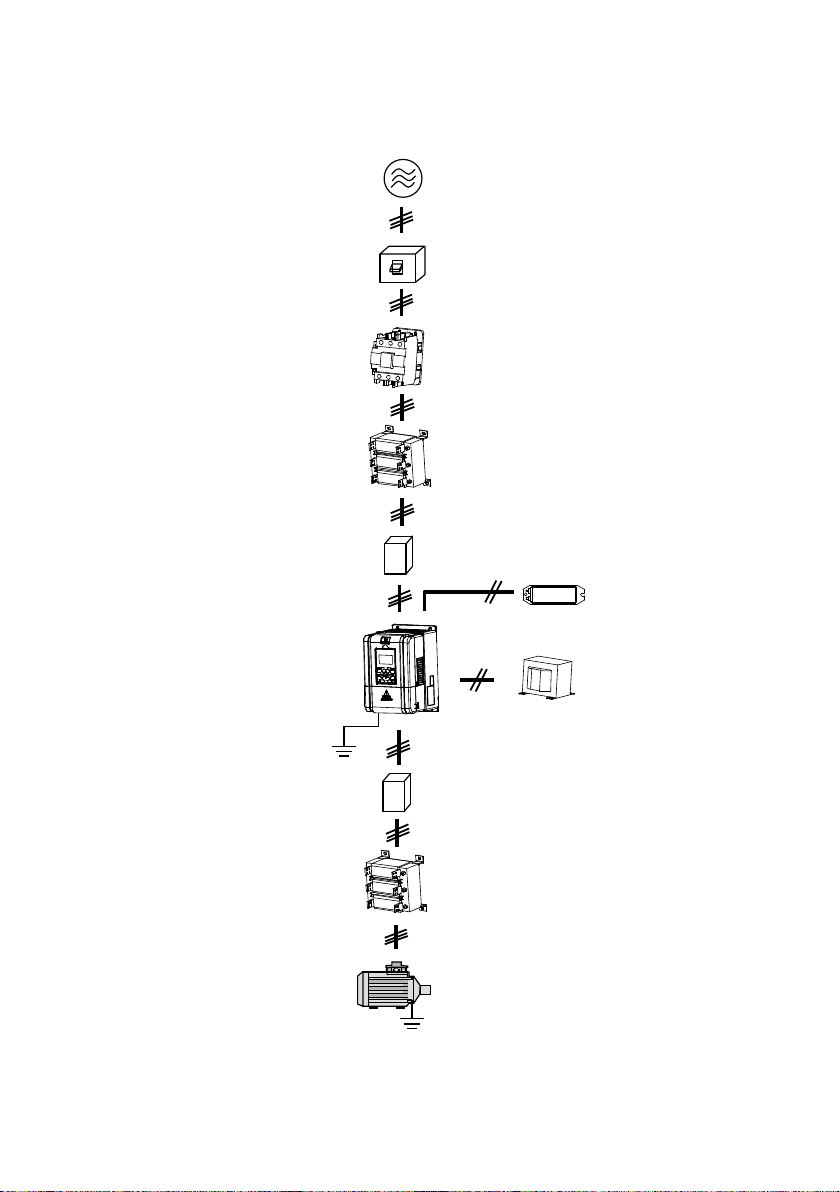
Three-phase AC power supply
MCCB
Contactor
Controller
Ground connection
Connection with peripheral devices
AC input reactor
EMI filter
EMI filter
AC output reactor
Motor
DC reactor
Braking resistor
(optional)
(optional)
Ground connection
Page 4

CONTENTS
Chapter 1 Safety Information and Precautions ............................................................................ 1
1.1 Safety Definiti on ............................................................................................................... 1
1.2 About Motor and Load ...................................................................................................... 1
1.3 Installation Limitation ........................................................................................................ 2
Chapter 2 Product Information ...................................................................................................... 3
2.1 Model Explanation ............................................................................................................ 3
2.2 Nameplate ....................................................................................................................... 3
2.3 Specifications ................................................................................................................... 4
2.4 Ratings............................................................................................................................. 6
2.5 Parts of Controller ............................................................................................................ 7
Chapter 3 Mechanical Installation ................................................................................................. 9
3.1 Instal la tion Prec autions .................................................................................................... 9
3.2 Requirement for the Installation Site ................................................................................. 9
3.3 Installation Direction and Space Requirements ............................................................... 10
3.4 Dimensions and Mounting Size ...................................................................................... 10
3.5 Panel Installation and Dismantle ..................................................................................... 12
3.6 Plastic C over Disma ntle ................................................................................................. 13
Chapter 4 Electrical Installation .................................................................................................. 15
4.1 Wiring Precautions ......................................................................................................... 15
4.2 Selection of Main Ci rcuit Per ipheral Devices ................................................................... 16
4.3 Main Circuit Terminals and Wiring ................................................................................... 16
4.3.1 Terminals Description......................................................................................... 17
4.3.2 Wiring Terminals ................................................................................................ 17
4.4 Control Terminals and Wire Connection .......................................................................... 18
4.4.1 Control Terminal Description .............................................................................. 19
4.4.2 Wire Jumper De s crip tion .................................................................................... 20
4.4.3 SCI Communicati on Terminal Description .......................................................... 20
4.4.4 Control Terminal Connection .............................................................................. 21
4.5 I/O Terminals and Wiring Connection .............................................................................. 26
4.5.1 I/O Card Terminal Description ............................................................................ 26
4.5.2 I/O Card Wire Jumper Description ...................................................................... 27
4.5.3 I/O Card Terminal Connection ............................................................................ 27
4.6 Encoder Card ................................................................................................................. 28
4.6.1 Encoder Cards Introduction ............................................................................... 28
Page 5

4.6.2 FD Description ................................................................................................... 28
4.6.3 DB15 Terminal ................................................................................................... 29
4.6.4 HD-PG2-OC-FD ................................................................................................ 29
4.6.5 HD-PG5-SINCOS-FD ........................................................................................ 32
4.6.6 HD-PG6-UVW-FD .............................................................................................. 34
4.6.7 HD-PG9-SC-FD ................................................................................................. 36
4.7 Meet EMC Requirement of Installation ............................................................................ 37
4.7.1 Correct E MC In stallation .................................................................................... 37
4.7.2 Wiring Requirement ........................................................................................... 38
4.7.3 Wiring Motor ...................................................................................................... 38
4.7.4 Ground Connections .......................................................................................... 39
4.7.5 EMI Filter ........................................................................................................... 39
4.7.6 Conduction, Radiation and Radio Frequency Interference Countermeasures ..... 40
4.7.7 Input and Output R eactor ................................................................................... 41
Chapter 5 Operation Instructions ................................................................................................ 43
5.1 Function Description ....................................................................................................... 43
5.1.1 Operation Mode ................................................................................................. 43
5.1.2 Control Mode ..................................................................................................... 44
5.1.3 Controller Sta te .................................................................................................. 44
5.1.4 Controller Running Mode ................................................................................... 44
5.2 Operating Instructions .................................................................................................... 45
5.2.1 Panel Description .............................................................................................. 45
5.2.2 Display State ..................................................................................................... 46
5.2.3 Panel Operation Exa mple s ................................................................................ 48
5.3 Initial Power On .............................................................................................................. 52
Chapter 6 Function Introduction ................................................................................................. 53
6.1 Group D: Display Parameters ......................................................................................... 54
6.1.1 Group D00 System State Par ameters ................................................................ 54
6.1.2 Group D01 Drive State Parameters .................................................................... 55
6.1.3 Group D02 Analogue State Display Parameters ................................................. 56
6.1.4 Group D03 Running State Parameters ............................................................... 57
6.1.5 Group D04 Encode r State Para meters ............................................................... 58
6.2 Group F: General Function Parameters .......................................................................... 59
6.2.1 Group F00 Basic Parameters ............................................................................. 59
6.2.2 Group F01 Protection of Pa rameters .................................................................. 61
6.2.3 Group F02 Start & Stop Parameters .................................................................. 62
Page 6

6.2.4 Group F03 Acceleration/Deceleration Parameters .............................................. 63
6.2.5 Group F04 Analogue Curve Parameters ............................................................ 64
6.2.6 Group F05 Speed Para mete rs ........................................................................... 65
6.2.7 Group F06 Weighin g C ompensation Param eters ............................................... 67
6.2.8 Group F07 Asynchrono us Motor Parameters...................................................... 68
6.2.9 Group F08 Motor Vector Control Speed-loop Param eters ................................... 71
6.2.10 Group F09 Current-loop Parameters ................................................................ 72
6.2.11 Group F10 Synchronous M ot or Parameters ..................................................... 72
6.2.12 Group F11 PG Parameters............................................................................... 73
6.2.13 Group F12 Di gital I/O Terminal Param eters ...................................................... 74
6.2.14 Group F13 Analo gue I/O Terminal Parameters ................................................. 77
6.2.15 Group F14 SCI Communication Parameters .................................................... 79
6.2.16 Group F15 Display Control Parameters ............................................................ 79
6.2.17 Group F16 Enhance Function Parameters ....................................................... 81
6.2.18 Group F17 Fa ult Protect Paramet ers ................................................................ 82
6.2.19 Group F18 PWM Parameters ........................................................................... 85
6.2.20 Group F19 Reserved ....................................................................................... 85
6.2.21 Group F20 Reserved ....................................................................................... 85
6.3 Group Y Manufacturer Func tio n Para me ter s ................................................................... 85
Chapter 7 Elevator Application Guidance ................................................................................... 87
7.1 Basic Debug Procedures ................................................................................................ 87
7.1.1 System Analy sis and Wire.................................................................................. 87
7.1.2 Set Basic Parameters ........................................................................................ 87
7.1.3 Motor Parameter Auto-tuning ............................................................................. 88
7.1.4 Inspection Running ............................................................................................ 92
7.1.5 Run Fast ............................................................................................................ 92
7.2 Terminal MS Run Mode Application ................................................................................ 93
7.2.1 Control Part Connection ..................................................................................... 93
7.2.2 Set Parameter ................................................................................................... 94
7.3 T erminal Analogue Run Mode Application ....................................................................... 96
7.3.1 Control Part Connection ..................................................................................... 96
7.3.2 Set Parameter ................................................................................................... 97
7.4 Power-off Battery Driven Run Mode Application .............................................................. 98
7.4.1 Basic Connection ............................................................................................... 98
7.4.2 Running Time Sequence .................................................................................... 98
Page 7

Chapter 8 Troubleshooting .......................................................................................................... 99
Chapter 9 Maintenance .............................................................................................................. 103
9.1 Daily Maintenance ........................................................................................................ 104
9.2 Periodical Maintenance ................................................................................................ 104
9.3 Replacing Damaged Parts ............................................................................................ 105
9.4 Unwanted Controller Recycling ..................................................................................... 105
Chapter 10 Accessories ............................................................................................................. 107
10.1 Panel Installation Assembly ........................................................................................ 107
10.1.1 Mounting Base ............................................................................................... 107
10.1.2 Extension Cable ............................................................................................ 107
10.2 Braking Resistor Selectio n .......................................................................................... 108
10.3 Protect ive Cover ......................................................................................................... 108
10.4 Power Regenerative Unit ............................................................................................ 108
Appendix A Parameters ............................................................................................................. 109
Appendix B Communication Protocol ...................................................................................... 129
Page 8

Communication Protocol
Elevator A pplicat ion Guidan ce
Troubleshooting
Maintenance
Accessories
Safety Information and Precautions
Product Information
Mechanical Installation
Electrical Installation
Operation Instructions
Function Introduction
Parameters
1
2
3
4
5
6
7
8
9
10
A
B
Page 9

Page 10
Shenzhen Hpmont Technology Co., Ltd Chapter 1 Safety Inform a ti on a nd Prec a uti ons
A Danger contains information which is critical for avoiding safety
a
Danger
Warning
Note
Chapter 1 Safety Information and Precautions
1.1 Safety Definition
Danger:
hazard.
Warning: A Warning contains information w hich is essential for avoiding
risk of damage to product or other equipments.
Note: A Note contains inf ormation wh ich helps t o ensure co rrect oper ation
of the product.
1.2 About Motor and L oad
Compared to the standar d frequency operation
The HD5L series controllers are voltage-type controllers and their output is PWM wave with
certain harmonic wave. T herefore, the temperature, noi se and vibration of the motor will be a little
higher than that at standard frequency operation.
Motor’s overload protecting threshold
When choose the adaptive motor, the controller can effectively implement the motor thermal
protection. Otherwise it must adjust the motor protection parameters or other protection
measures to ensure t hat the mot or is at a safe a nd reliab le operation.
Lubrication of mechanical devices
At long time low-speed operation, it should provide periodical lubrication maintenance for the
mechanical devices such as gear box and geared motor etc. to make sure the drive results meet
the site need.
Check the insulation of the motor
For the first time using of the motor or after long time storage, it need check the insulation of the
motor to avoid damage the controller because of the worse insulation motor.
Note:
Please use a 500V Mega-Ohm-Meter to tes t and the in s u lation resistanc e m ust be higher than
5Mohm.
1
HD5L Series Controller User Manual ―1―
Page 11
Chapter 1 Safety Inform a ti on a nd Prec a uti ons S he nzhen Hpmont Technology Co., Ltd
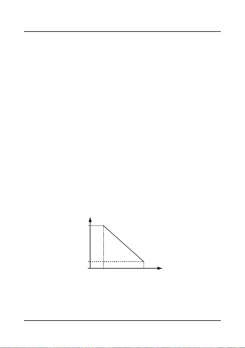
80%
100%
1000 4000
Controller’s rat ed cu r r ent
Altitude(m)
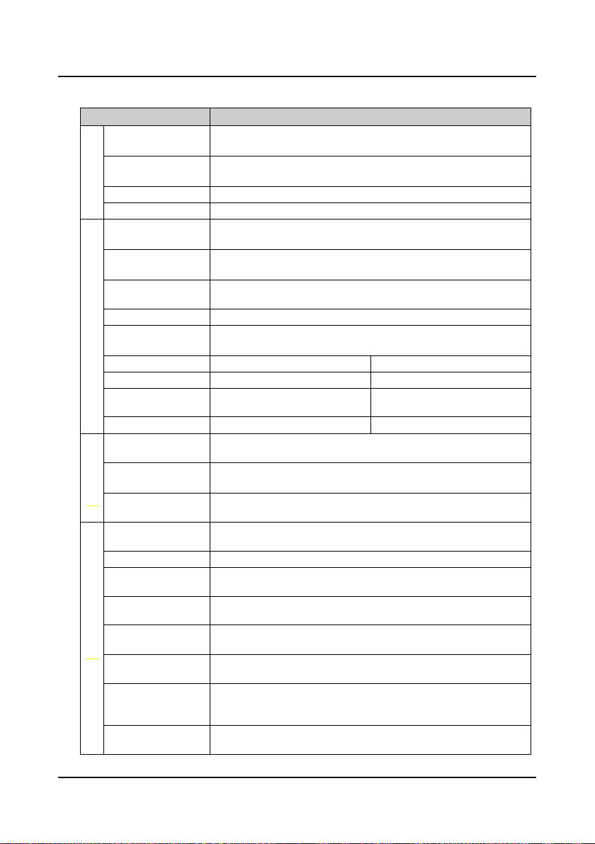
1.3 Installation Limitation
No capacitor or varistor on the output side
Since the controller outpu t is PWM wave, it is strictly forbidden to connect capacitor for improving
the power factor or varistor for lightning protection to the output terminal s so as to avoid the
controller fault tripping or component damage.
Contactors and circuit breakers connect e d t o the out put of t he controller
If circuit breaker or contactor needs to be connected between the controller and the motor, be
sure to operate these circuit breakers or contactor when the controller has no output, so as to
avoid any damage to the controller.
Rated voltage
The controller i s prohibited to be us ed bey ond the speci fied range o f oper ation voltage. If need ed,
please use the suitable voltage regulation device to change the vol tage.
Change three-phase input to single-phase input
For three-phase input controller, the users should not change it to be single-phase input.
If you have to use s ingle-phase power supply, you should disable the in put phase-loss protection
function. And the bus-voltage and current ripple will increase, which n ot only influences the life of
electrolytic capacitor but also deteriorates the performance of the controller. In that case, the
controller must be derating and should be within the controller 60% rated value.
Lightning surge protection
The controller internal design has lightning surge overcurrent protection circuit, and has certain
self-protection capacity against the lightning.
Altitude and derating
In the altitude exceeded 1000 meters area, since the heatsink efficiency will be reduced because
of the tenuous air, the controller should be derating. Figure 1-1 is the derating curve of the
controller rated current and the altitude.
Figure 1-1 Derating curve of controller rated current and altitude
―2― HD5L Series Controller User Manual
Page 12
Shenzhen Hpmont Technology Co., Ltd Chapter 2 Product Information
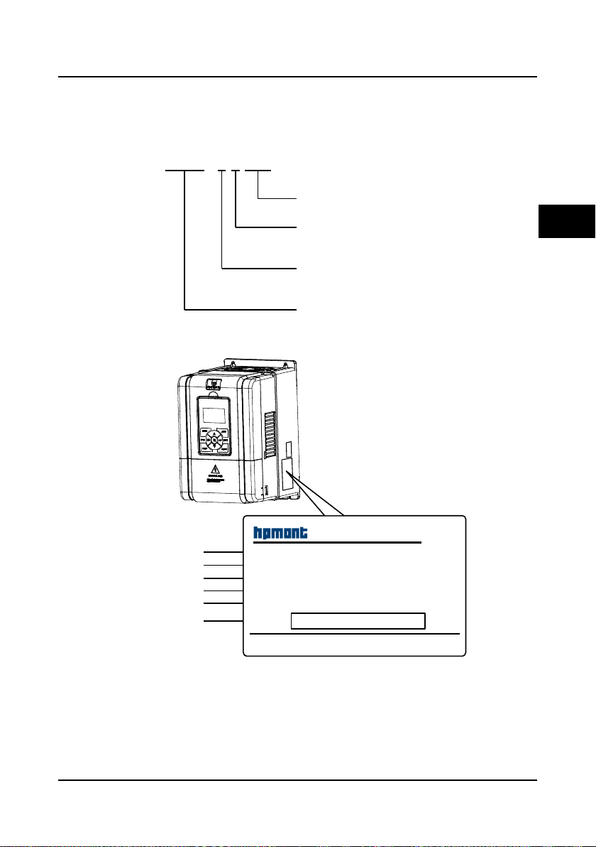
HD5L - 4 T 5P5
2 : 200-240V
4 : 380-460V
Refer to section 2.4 about rati ng
S : single-phase
T : three-phase
Elevator c ontroller
Adaptive motor power
Input phases
Voltage ratings
Product seri es
Shenzhen Hpmont Technology Co., Ltd
HD5L-4T5P5
MODEL:
POWER:
INPUT:
OUTPUT:
Version:
S/N:
5.5kW
3PH380-460V15A50/60Hz
1.00
8.5kVA0-460V 13A0-100Hz
Barcode
Productmodel
Adaptivemotor
Inputspecification
Outputspecification
Softwareversion
Serialnumber
Chapter 2 Product Information
2.1 Model Explanation
2.2 Nameplate
2
HD5L Series Controller User Manual ―3―
Page 13
Chapter 2 Product Information Shenzhen Hpmont Technology Co., Ltd
2.3 Specifications
Item Specification
Rated voltage and
frequency
Electrical
Accuracy
Output voltage 0-input voltage
Output frequency 0-100.00Hz
Maximum current
Control mode
Operation command
Performance
control mode
Speed setting mode Digital setting, analogue setting, SCI communication setting
Speed setting
resolution
Speed control accuracy SVC: ± 0.5% VC: ± 0.05%
Speed control range SVC: 1:100 VC: 1:1000
Torque control
response
Start torque SVC: 180% rated-torque /0.5Hz VC: 200% rated-torque /0Hz
Parameter upload and
Characteristic
download function
Programmable I/O
interface
Communication
protocol
Auto-inspection
Over-speed protection To make sure safe running, elevator over-speed protection is provided
Speed deviation
protection
Up/down forced
Protection
deceleration function
I/O phase loss
protection
Motor temperature
detection
Power output
grounding fault
protection
Power output short
circuit protection
Single-phase: 200-240V, 50/60Hz
Three-phase: 380-460V, 50/60Hz
Voltage: fluctuation within ± 10%, imbalance rate < 3%
Frequency: ± 5%
150% rated output current for 2 minutes
180% rated output current for 10 seconds
V/f control; Open-loop vector control (SVC);
Closed-loop vector control (VC)
Panel control; external terminal control; host computer communication
control via SCI communication port
Digital setting: 0.01Hz
Analogue setting: 0.1% × max-frequency
SVC: < 200ms VC: < 50ms
To achieve parameters uploading or downloading
The programmable input interface has up to 34 functions
The pragrammable output interface has up to 19 functions
Controller is built-in MODBUS communication protocol
To eliminate the potential safety problems, safety inspection for the
peripheral devices is provided when power is on
To eliminate the potential safety problems, speed deviation detection
protection is provided
Up/down forced deceleration function, to avoid climbing elevator or plunging
elevator
I/O phase loss auto-detect and alarm function
Real time detection for the motor temperature
Power output grounding fault protection is enabled
Power output short circuit protection is enabled
―4― HD5L Series Controller User Manual
Page 14

Shenzhen Hpmont Technology Co., Ltd Chapter 2 Product Information
cation
Item Specification
Analogue supply
Digital supply +24V, maximum current 200mA
I/O feature
Analogue input
Analogue output AO1, AO2: 0-10V/0-20mA (voltage/current is selectable)
Digital input DI1-DI6 (control board); DI7-DI12 (I/O card)
Digital output DO1, DO2
Programmable relay
output
Communi-
SCI communication RS-485 interface
+10V, maximum current 100mA
-10V, maximum current 10mA
AI1 (control board): voltage 0-10V
AI2, AI3 (control board): -10V-+10V/0-20mA (voltage/current is
selectable)
AI4 (I/O card): -10V-+10V/0-20mA (voltage/current is selectable, and
differential input is supported)
R1A/R1B/R1C (control board)
R2A/R2B/R2C; R3A/R3B/R3C; R4A/R4B/R4C (I/O card)
Contact rating 250VAC/3A or 30VDC/1A
2
Panel
LCD display
Parameter copy To achieve quick parameter copy
Operation temperature
Environment
Storage temperature -40-+70℃
Location for use
Altitude Less than 1000 meters, otherwise should be derating use
Humidity Less than 95%RH, non-condensing
Ocsillation Less than 5.9m/s2 (0.6g)
Encoder card
Options
About panel
Enhanced protection Protective cover (HD-CK-Frame4)
Power unit Power regenerative unit (HDRU)
Function parameter setting, check the state parameters and the fault code
etc.
-10-+40℃, air temperature fluctuation is less than 0.5℃/min
The derating value of the output current of the controller shall be 2% for each
degree centigrade above 40℃. Max. allowed temperature is 50℃
Indoor, preventing from direct sunlight, no dust, corrosive, flammable gases,
oil mist, water vaper, dripping or salt etc.
OC encoder card with frequency demultiplication output (HD-PG2-OC-FD)
SINCOS encoder card with frequency demultiplication output
(HD-PG5-SINCOS-FD)
Line drive encoder card with frequency demultiplication output
(HD-PG6-UVW-FD)
Serial Communication encoder card with frequency demultiplication output
(HD-PG9-SC-FD) (support Endat)
Mounting base to panel (HD-KMB)
1 meter extension cable to panel (HD-CAB-1M)
2 meter extension cable to panel (HD-CAB-2M)
3 meter extension cable to panel (HD-CAB-3M)
6 meter extension cable to panel (HD-CAB-6M)
HD5L Series Controller User Manual ―5―
Page 15
Chapter 2 Product Information Shenzhen Hpmont Technology Co., Ltd
(kVA)
(A)
(A)
(kW)
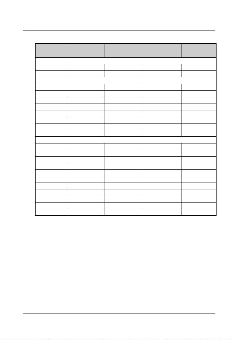
2.4 Ratings
Model
HD5L-2S2P2 3.8 24.1 10 2.2
HD5L-2S3P7 5.9 40 17 3.7
HD5L-2T3P7 5.9 19 17 3.7
HD5L-2T5P5 8.5 28 25 5.5
HD5L-2T7P5 11 35 32 7.5
HD5L-2T011 16 47 45 11
HD5L-2T015 21 62 55 15
HD5L-2T018 24 77 70 18.5
HD5L-2T022 30 92 80 22
HD5L-2T030 39 113 110 30
HD5L-4T2P2 3.4 7.3 5.1 2.2
HD5L-4T3P7 5.9 11.9 9.0 3.7
HD5L-4T5P5 8.5 15 13 5.5
HD5L-4T7P5 11 19 17 7.5
HD5L-4T011 16 28 25 11
HD5L-4T015 21 35 32 15
HD5L-4T018 24 39 37 18.5
HD5L-4T022 30 47 45 22
HD5L-4T030 39 62 60 30
HD5L-4T037 49 77 75 37
HD5L-4T045 59 92 90 45
Rated capacity
Single-phase power supply: 200-240V, 50/60Hz
Three-phase power supply: 200-240V, 50/60Hz
Three-phase power supply: 380-460V, 50/60Hz
Rated input current
Rated output current
Motor power
―6― HD5L Series Controller User Manual
Page 16
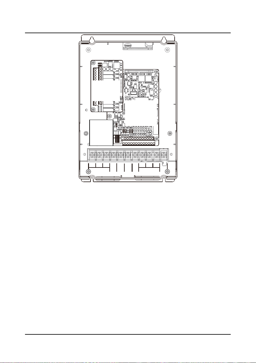
Shenzhen Hpmont Technology Co., Ltd Chapter 2 Product Information
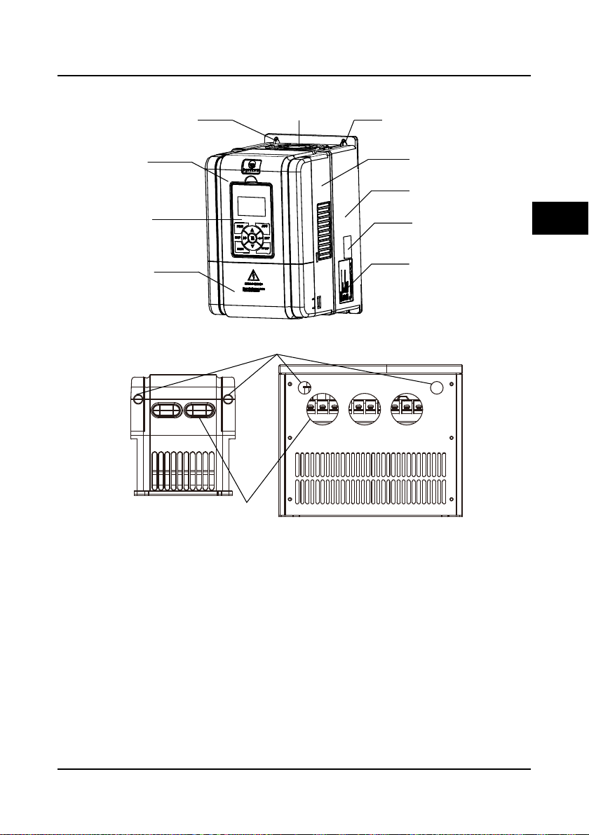
Mountinghole
Certification
Bottomenclosure
Middleenclosure
Displaypanel
Uppercover
Fancover
Lowercover
Mountinghole
Nameplate
Controlterminalconnectionhole
Plastic structure Metal structure
Powerterminal
connectionhole
2.5 Parts of Controller
2
HD5L Series Controller User Manual ―7―
Page 17
Chapter 2 Product Information Shenzhen Hpmont Technology Co., Ltd
PE
BR
P1
(+)
(-)
U
V W
MOTOR
L1
L2
L3
POWER
I/O card
Refer to section4.5
Control board
Refer to section4.4
Encoder card
(optional)
Refer to section4.6
―8― HD5L Series Controller User Manual
Page 18
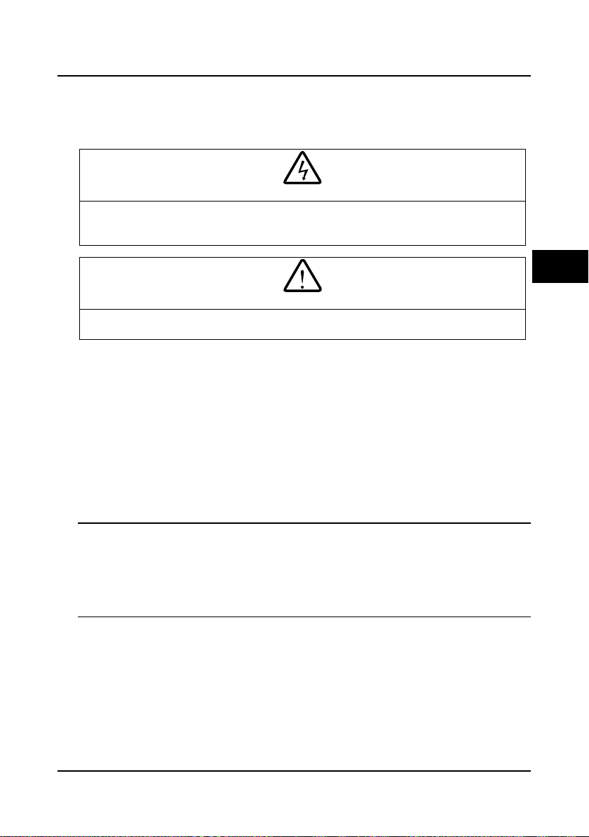
Shenzhen Hpmont Technology Co., Ltd Chapter 3 Mechanical Installation
Danger
Warning
Chapter 3 Mechanical Installation
3.1 Installation Precautions
• Do not install if the controller is imcomplete or impaired.
• Make sure that the controller is far from the explosive and combustible things.
• Do not operate the controller until the power is cut-off 10 minutes later.
• It is required not only carry the panel and the cover but also the controller bottom enclosure.
• Do not play metal into the controller when insta l ling.
123
3.2 Requirement for the Installation Site
Ensure the installation site mee ti ng the foll ow ing requirements:
• Do not instal l at the direc t sunlight, moisture, water droplet location;
• Do not install at the combustible, explosive, corrosive gas and liquid location;
• Do not install at the oily dust, fiber and metal powder location;
• Be vertical installation on fire-retardant material with a strong support;
• Make sure adequate cooling space for the controller so as to keep the ambient temperature
between - 10-+ 40℃;
• Install at where the vibration is less than 5.9m/s
Note:
1. It needs derating use if the controller operation temperature excee ds 40℃ . The derating value
of the output current of the controller shall be 2% for each degree centigrade. Max. allowed
temperature is 50℃.
2. Keep ambient temperature between -10-+40℃. It can improve the controller operation
perform ance if install at the location with good ventilation or cooling devices.
2
(0.6g).
3
HD5L Series Controller User Manual ―9―
Page 19
Chapter 3 Mechanical Installation Shenzhen Hpmont Technology Co., Ltd
≥30
≥50
≥30
≥50
W
H
H2
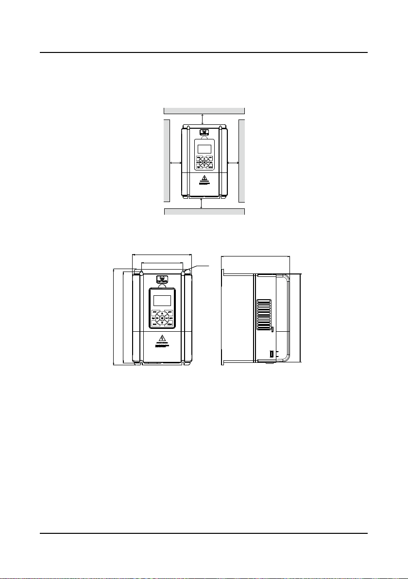
3.3 Installation Direction and Space Requirem ent s
To achieve good cooling efficiency, install the controller perpendicularly and always provide the
following space to allow normal heat dissipation. The requirements on mounting space and
clearance are shown in Figure 3-1.
Figure 3-1 Installation of the controller
3.4 Dimensions and Mounting Size
W1
H1
4-Ød
Dimensions figure 1
D
―10― HD5L Series Controller User Manual
Page 20
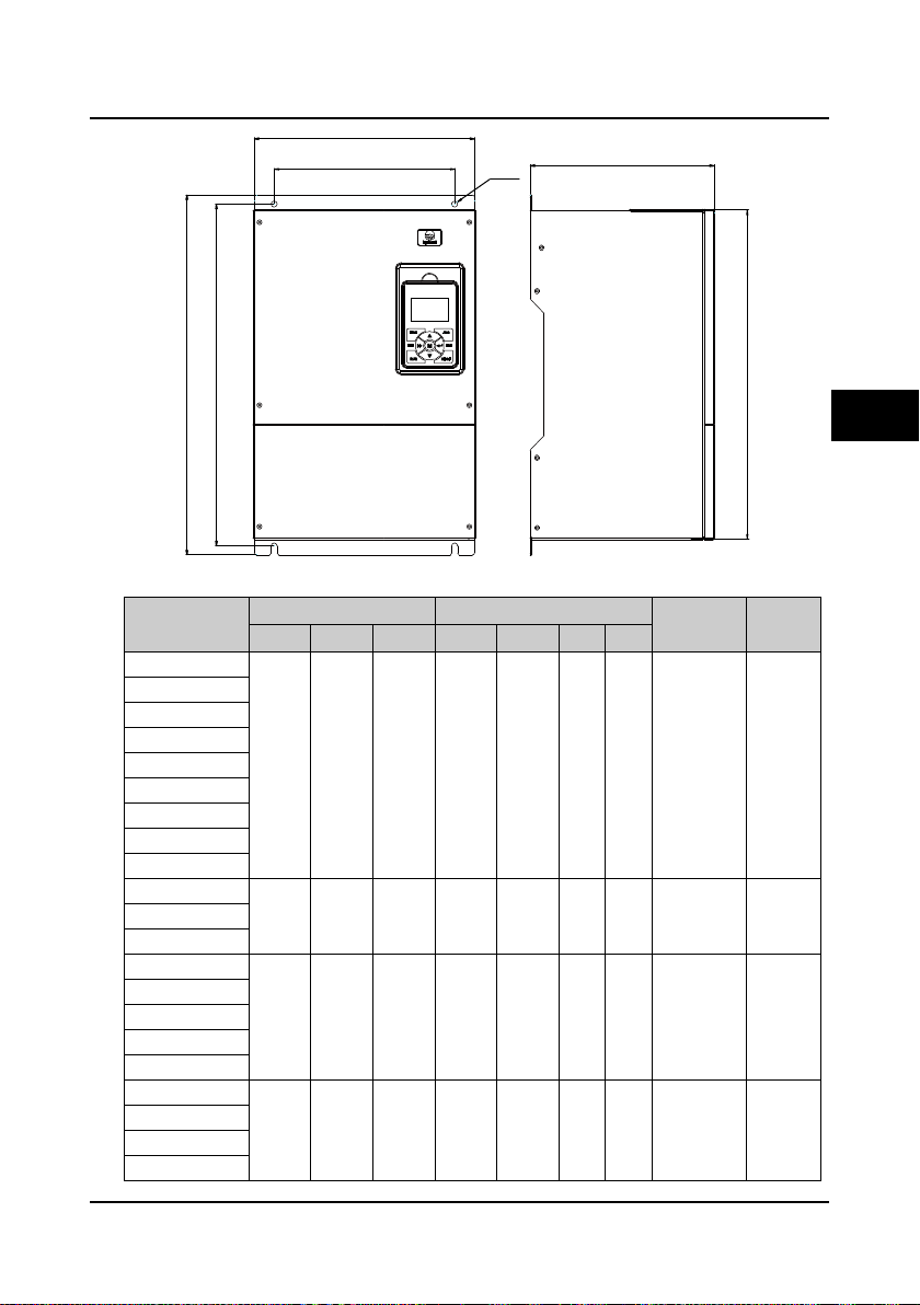
Shenzhen Hpmont Technology Co., Ltd Chapter 3 Mechanical Installation
W
H
H2
W1
4-Ød
D
H1
3
(kg)
Figure
Dimensions figure 2
Table 3-1 HD5L dimensions
Model
HD5L-2S2P2
HD5L-2S3P7
HD5L-2T3P7
HD5L-2T5P5
HD5L-4T2P2
HD5L-4T3P7
HD5L-4T5P5
HD5L-4T7P5
HD5L-4T011
HD5L-2T7P5
HD5L-4T015
HD5L-4T018
HD5L-2T011
HD5L-2T015
HD5L-2T018
HD5L-4T022
HD5L-4T030
HD5L-2T022
HD5L-2T030
HD5L-4T037
HD5L-4T045
Dimensions (mm) Mounting size (mm)
W H D W1 H1 H2 d
200 299 210 146 286 280 5 5.8 1
235 353 222 167 337 330 7 8.2 1
290 469 240 235 445 430 8 20.4 2
380 598 290 260 576 550 10 48 2
Gross weight
HD5L Series Controller User Manual ―11―
Page 21
Chapter 3 Mechanical Installation Shenzhen Hpmont Technology Co., Ltd
ENT
JOG
PRG
RUN
STOP
SHF
ENT
JOG
PRG
RUN
STOP
SHF
1
2
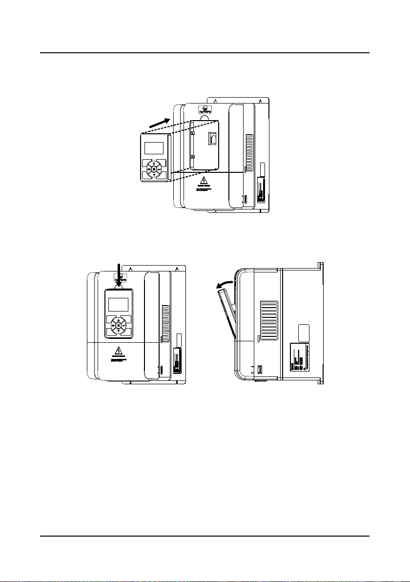
3.5 Panel Installation and Dismant l e
According to the direction of the Figure 3-2, press the panel until hear a “click” sound. Do not
install the panel from other dir ections or it wil l cause p oor contact.
Figure 3-2 Installation of the panel
There are two steps in Figure 3-3.
First, press the hook of the panel according to the direction 1.
Second, take out of the panel according to the direction 2.
Figure 3-3 Dismantle of the panel
―12― HD5L Series Controller User Manual
Page 22
Shenzhen Hpmont Technology Co., Ltd Chapter 3 Mechanical Installation
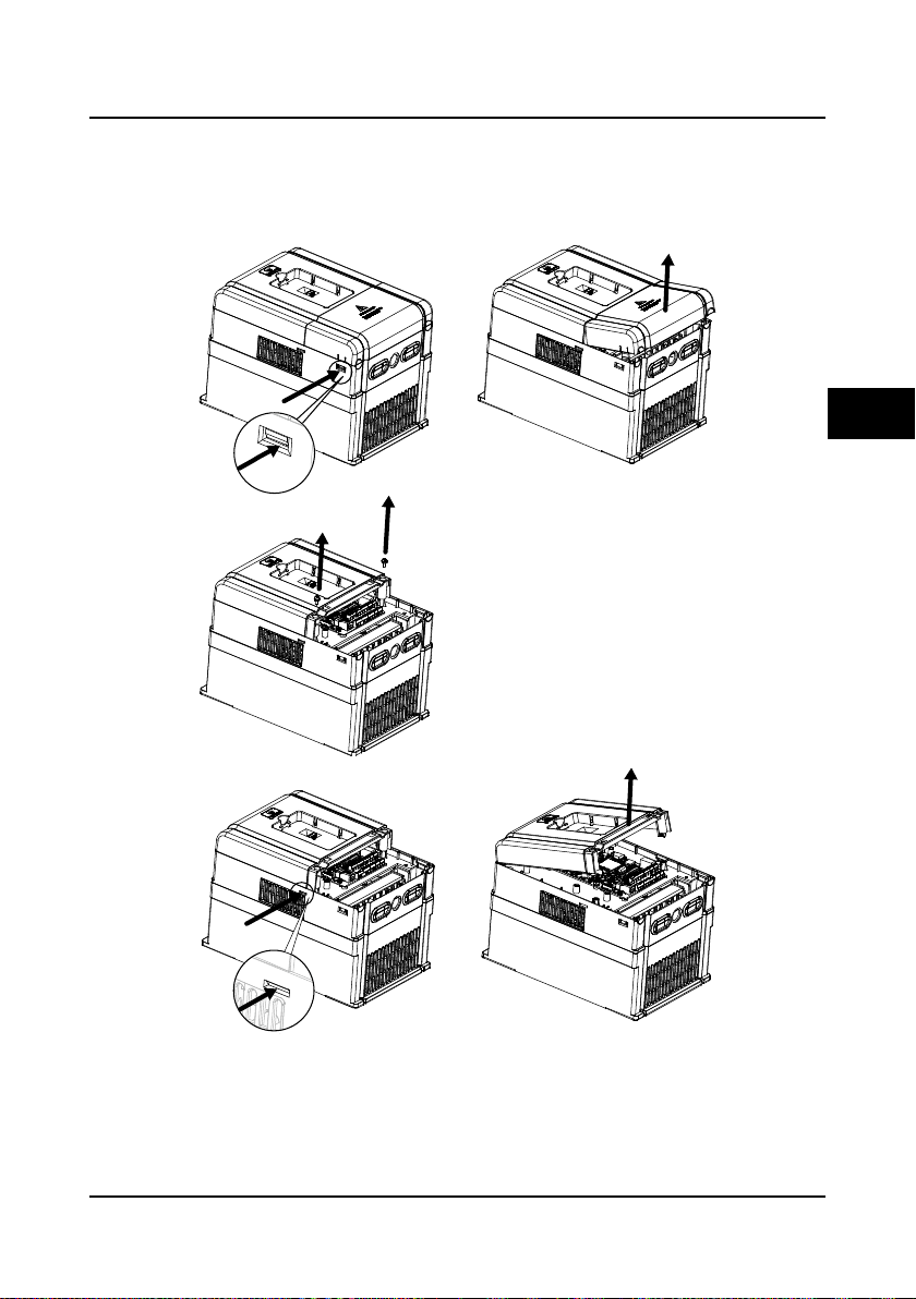
(a)
1.Extrude the hooks at both side together,
take off the lower cover, as (a).
2.Dismantle the screws of upper cover, as (b).
3.Extrude the hooks at both side together,
take off the upper cover, as(c).
The removing proceeses
of plastic coverboard:
(b)
(c)
3.6 Plastic Cover Dismantle
The upper cover and the lower cover of the HD5L series controller are removable. The dismantle
step is shown as Figure 3-4.
Before removing the upper cover, please take away the panel.
3
Figure 3-4 Dismantle of the plastic cover
HD5L Series Controller User Manual ―13―
Page 23

Page 24
Shenzhen Hpmont Technology Co., Ltd Chapter 4 Electrical Installation
Danger
Warning
Chapter 4 Electrical Installat ion
4.1 Wiring Precautions
• Only qualified electrical engineer can perform wiring job.
• Only when the power supply switch is completely off can you do the wiring job.
• You can’t open the controller cover to do wiring operation until the power is cut-off 10 minutes later. Do
not wire or detach the controller internal devices at power-on situation.
• Do not do wiring operation until the internal charge indicator of the controller is off and the voltage
between (+) and (-) of the main circuit terminals is below 36V.
• Check the wiring carefully before connecting emergency stop or safety circuit.
• The earth terminal PE of the controller must be reliable earthing. It must use two separate earth wire due
to the leakage current from the controller to ground.
• It must use Type B mode when utilize earth leakage protection devices(ELCB/RCD).
• Do not touch the wire terminals of the controller when it is live. The main circuit terminals is neither
allowed connecting to the enclosure nor short-circuiting.
• Do not do dielectric strength test on the controller.
• Do wiring connection of the braking resistor or the braking unit according to the wiring figure.
• Make sure the terminals are fixed tightly.
• Do not connect the AC supply cable to the output terminals U/V/W of the controller.
• Do not connect the phase-shifting capacitors to the output circuit.
• The controller DC bus terminals must not be short-circuited.
4
HD5L Series Controller User Manual ―15―
Page 25
Chapter 4 Electri c al I ns tallation Shenzhen Hpmont Technology Co., Ltd
Danger
Warning
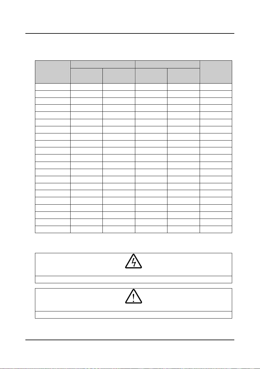
4.2 Selection of Main Circuit Peripheral Devices
Please r efer to the Table 4-1 for the recommended specification s.
Table 4-1 HD5L series controller I/O wiring specification
Input Protection Main Circuit
Model
HD5L-2S2P2 32 20 4.0 2.5 ≥0.5
HD5L-2S3P7 63 32 4.0 4.0 ≥0.5
HD5L-2T3P7 40 32 4.0 4.0 ≥0.5
HD5L-2T5P5 63 40 6.0 6.0 ≥0.5
HD5L-2T7P5 63 40 6.0 6.0 ≥0.5
HD5L-2T011 100 63 16 16 ≥0.5
HD5L-2T015 125 100 25 25 ≥0.5
HD5L-2T018 160 100 25 25 ≥0.5
HD5L-2T022 200 125 35 35 ≥0.5
HD5L-2T030 200 125 50 50 ≥0.5
HD5L-4T2P2 16 10 1.5 1.5 ≥0.5
HD5L-4T3P7 25 16 2.5 2.5 ≥0.5
HD5L-4T5P5 32 25 4.0 4.0 ≥0.5
HD5L-4T7P5 40 32 4.0 4.0 ≥0.5
HD5L-4T011 63 40 6.0 6.0 ≥0.5
HD5L-4T015 63 40 6.0 6.0 ≥0.5
HD5L-4T018 100 63 10 10 ≥0.5
HD5L-4T022 100 63 16 16 ≥0.5
HD5L-4T030 125 100 25 25 ≥0.5
HD5L-4T037 160 100 25 25 ≥0.5
HD5L-4T045 200 125 35 35 ≥0.5
MCCB
(A)
Contactor
(A)
Supply Cables
(mm2)
Motor Cables
(mm2)
Control Circuit
(mm2)
4.3 Main Circuit Terminals and Wiring
• The bare portions of the power cables must be bound with insulation tapes.
• Ensure that AC supply voltage is the same as controller’s rated input voltage.
―16― HD5L Series Controller User Manual
Page 26
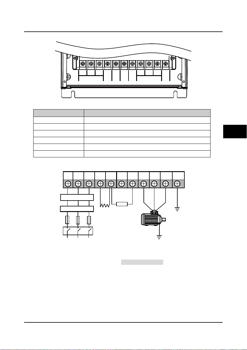
Shenzhen Hpmont Technology Co., Ltd Chapter 4 Electri c al I ns tallation
MOTOR
PE
L3
L1 L2
W
U V
P1
L1 L2 L3 (+) (-) BR U V W PE
P1
Optional EMIfilter
Optional ACreactor
Mains supply
Braking resistor
Fuses
DC reactor
(external)
Supply ground
4.3.1 Terminals Description
(+) (-)
POWER
BR
Figure 4-1 Power terminal layout of HD5L controller
Table 4-2 HD5L power terminal function description
Terminal Function Description
L1、L2、L3 Three-phase AC power input terminals
U、V、W Output terminals, connect to three-phase AC motor
P1、(+) DC reactor connection terminals
(+)、(-) DC supply input terminals; DC input terminals of power regenerative unit
(+)、BR Braking resistor connection terminals
PE Earth terminal, connect to the ground
4.3.2 Wiring Terminals
Figure 4-2 HD5L power terminal connection
During trial operation, make sure that the elevator will go up when the UP command is enabled.
If the elevator goes down, set the parameter F00.08 (run direc tion) to be the reverse value.
4
HD5L Series Controller User Manual ―17―
Page 27

Chapter 4 Electri c al I ns tallation Shenzhen Hpmont Technology Co., Ltd
Danger
Warning
SCI communicationterminal
Wirejumper
CN5andCN6
WirejumperCN9
Controlterminal
Wirejumper
CN7 andCN8
4.4 Control Terminals and Wire Connection
• The control circuit is designed as ELV (Extra Low Voltage) circuit and basically isolated with the
power circuit. Do not touch the control circuit when the controller is on power.
• If the control circuit is connected to the external devices with live touchable port (SELV circuit), it
should increase an additional isolating barrier to ensure that SELV classification of external devices
not be changed.
• If connect the communication terminal of the control circuit to the PC, you should choose the
RS485/232 isolating converter which meets the safety requirement.
In order to efficiently suppress the interference to control signals, the length of signal cables
should be less than 50m and keep a distance of at least 0.3m from the power lines. Please use
twisted-pair shie lded cable s for analogue input and output signals.
The positions of control terminal, wire jumper and SCI commu nicati on port in the control board
are shown in Figure 4-3.
Figure 4-3 Positions of control terminal, wire jumper and SCI port in the control board
―18― HD5L Series Controller User Manual
Page 28
Shenzhen Hpmont Technology Co., Ltd Chapter 4 Electrical Install a ti on
+10
-10
AI1 AI2
AI3
DI1 DI2 DI3 DI4 DI5 DI6 COM R1ACOM
GND
AO1 AO2
P24 SEL DO1 R1C
GND COM CME DO2 R1B
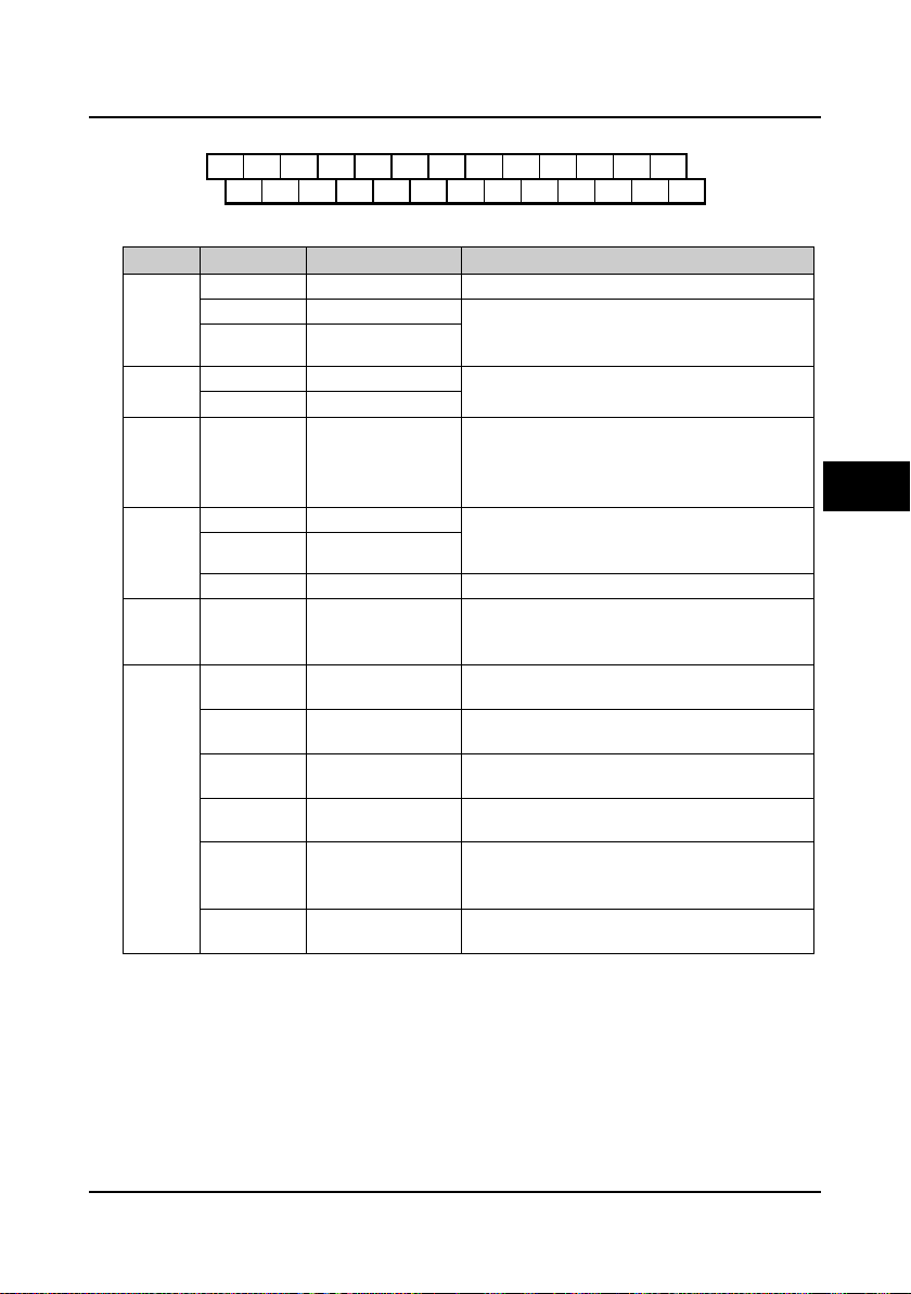
4.4.1 Control Terminal Description
Figure 4-4 Control terminal layout
Table 4-3 Control terminal function description
Item Terminal Name Function Description
AI1 Anglogue input 1 Input voltage: 0-10V (input impedance: 34kΩ)
Analogue
input
Analogue
output
Digital
input
Digital
output
Relay
output
Power
source
AI2 Anglogue input 2 Input voltage/current is selectable;
AI3 Anglogue input 3
AO1 Anglogue output 1
AO2 Anglogue output 2
DI1-DI6 Digital input 1-6
DO1 Digital output 1 Programmable optical-coupled isolation, open
DO2 Digital output 2
CME DO1 reference ground Isolated from COM, default short connected COM
R1A/ R1B/ R1C Relay contact output
+10V +10V power supply
-10V -10V power supply
GND
P24 +24V power supply
SEL
COM
+/-10V power
reference ground
Digital input common
terminal
Digital reference
ground
Input voltage: -10V-10V (input impedance: 34kΩ);
Input current: 0-20mA (input impedance: 500Ω)
Output voltage/current signal: 0-10V/0-20mA;
Programmable output
Programmable bipolar optional input signal
Input voltage: 0-30VDC
DI1-DI5 input impedance: 4.7kΩ;
DI6 input impedance: 1.6kΩ
collector output
Output voltage: 0-30VDC, max-output current 50mA
Programmable output, contact rating: 250VAC/3A or
30VDC/1A
R1B,R1C: normally closed; R1A,R1C: normally open
Analogue input use +10V as reference supply,
maximum output current is 100mA
Analogue input use -10V as reference supply,
maximum output current is 10mA
Analogue site, isolated from COM
Digital input use +24V as supply, maximum output
current is 200mA
Factory settings default SEL and P24 are connected.
Disconnected SEL and P24 when use external power
to drive DI1-DI6
Digital site, isolated from CME
4
HD5L Series Controller User Manual ―19―
Page 29
Chapter 4 Electri c al I ns tallation Shenzhen Hpmont Technology Co., Ltd
CN5
1
3
CN6
1
3
CN7
1
3
CN8
1
3
CN9
13
Port pin
Port signal
RJ45
1
+5V2485+3+5V4GND5GND6GND7485-8Reserved
1 8
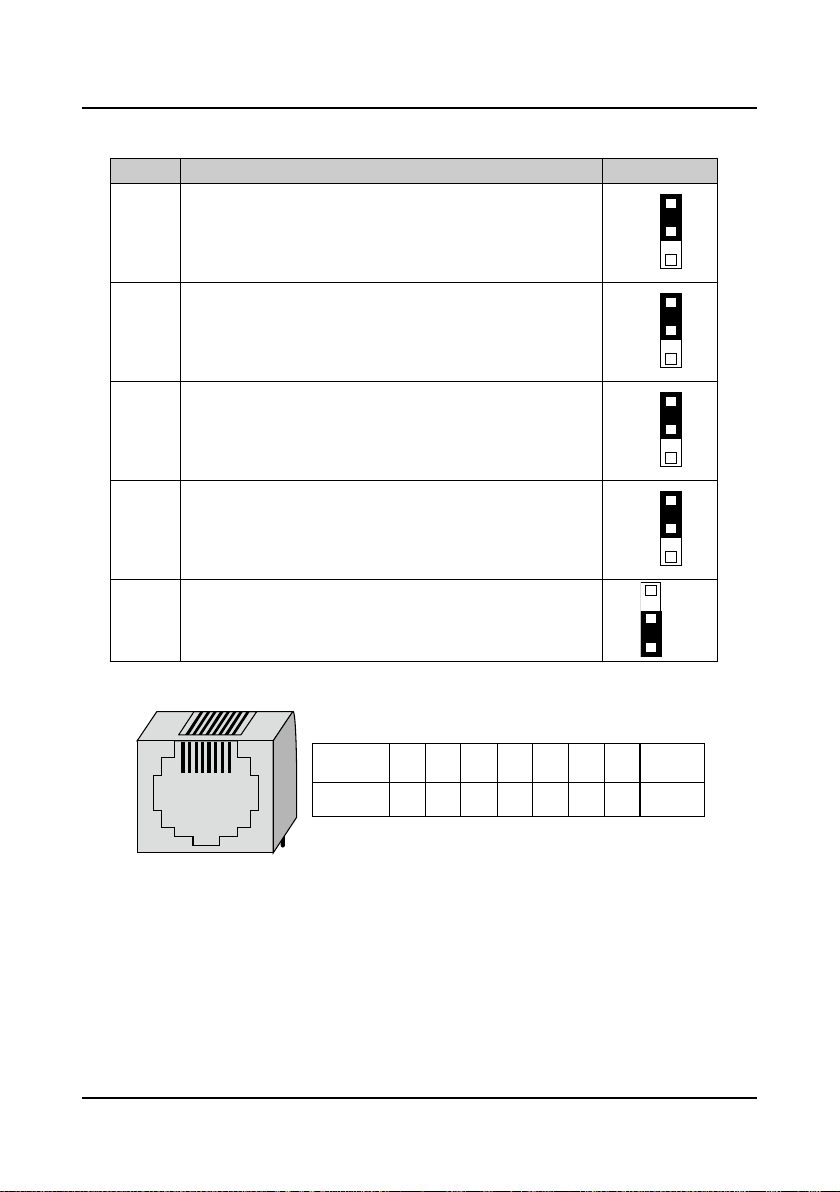
4.4.2 Wire Jumper Description
Table 4-4 Wire jumper function and setting description on the control board
Jumper Function and setting description Factory setting
AI2 analogue input channel can select voltage or current signal.
When pin 1 and pin 2 of the CN5 are short-circuited, AI2 channel
CN5
inputs voltage signal;
When pin 2 and pin 3 of the CN5 are short-circuited, AI2 channel
inputs current signal.
AI3 analogue input channel can select voltage or current signal.
When pin 1 and pin 2 of the CN6 are short-circuited, AI3 channel
CN6
inputs voltage signal;
When pin 2 and pin 3 of the CN6 are short-circuited, AI3 channel
inputs current signal.
AO1 analogue output channel can select voltage or current signal.
When pin 1 and pin 2 of the CN7 are short-circuited, AO1 channel
CN7
outputs voltage signal;
When pin 2 and pin 3 of the CN7 are short-circuited, AO1 channel
outputs current signal.
AO2 analogue output channel can select voltage or current signal.
When pin 1 and pin 2 of the CN8 are short-circuited, AO2 channel
CN8
outputs voltage signal;
When pin 2 and pin 3 of the CN8 are short-circuited, AO2 channel
outputs current signal.
SCI communication can select proper resistance.
When pin 2 and pin 3 of the CN9 are short-circuited, no resistance;
CN9
When pin 1 and pin 2 of the CN9 are short-circuited, select the proper
resistance.
4.4.3 SCI Communication Terminal Description
Figure 4-5 SCI communication terminal and description
―20― HD5L Series Controller User Manual
Page 30
Shenzhen Hpmont Technology Co., Ltd Chapter 4 Electri c al I ns tallation
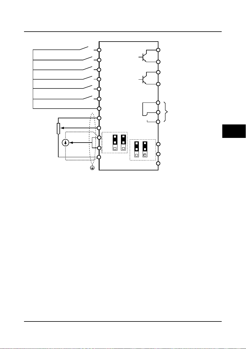
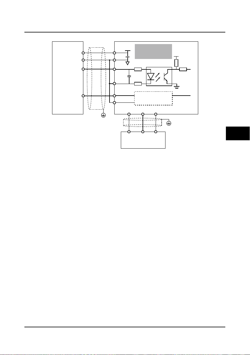
DI1
DO2
DO1
CME
R1A
R1C
R1B
GND
AO1
AO2
DI2
DI3
DI4
DI5
DI6
COM
AI1
AI2
+10
HD5L
Control board
AI3
GND
COM
PE
CN5
1
3
CN6
1
3
CN7
1
3
CN8
1
3
Multi-function inputterminal1
Multi-function inputterminal2
Multi-function inputterminal3
Multi-function inputterminal4
Multi-function inputterminal6
Multi-function inputterminal5
Digital ground
DO1 referenceground
DO2 reference ground
AI 1
AI 2
Analogue ground
Analogue ground
Analogue outputchannel2
Analogue outputchannel1
Programmable relayoutput
Programmable open-collector
output channel1
Programmable open-collector
output channel2
AI
3
Shielded cable
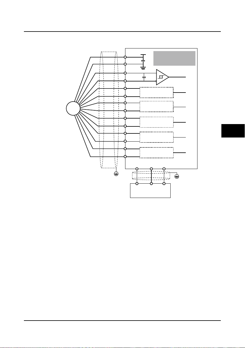
4.4.4 Control Terminal Connection
4
HD5L Series Controller User Manual ―21―
Figure 4-6 HD5L control circuit connection diagram
Page 31

Chapter 4 Electri c al I ns tallation Shenzhen Hpmont Technology Co., Ltd
+ 3.3V
+
-
R
+ 24V
COM
P24
SEL
K
DI1...DI6
+
-
12-30V
DC
Current
Dry contact connection
using external power
Dry contact connections
1. If the internal 24V power supply is used, the connection is as shown in Figure 4-7. (The SEL
and the P24 are short-circuited a t factory)
P24
+ 24V
SEL
Dry contact connection
using internal power
+ 3.3V
Current
+
R
K
DI1...DI6
COM
Figure 4-7 Dry contact connection when using internal 24V power
-
2. If the external power supply is used, the connection is as shown in Figure 4-8. (Note th at the
SEL and the P24 are not short-circuited)
Figure 4-8 Dry contact connection when using external power
―22― HD5L Series Controller User Manual
Page 32

Shenzhen Hpmont Technology Co., Ltd Chapter 4 Electri c al I ns tallation
+ 3.3V
+
-
R
+ 24V
P24
SEL
DI1
+ 3.3V
+
-
COM
DI6
R
6
1
12-30V
DC
+
-
External
controller
Source connection
using external power
+ 3.3V
+
-
R
+ 24V
P24
SEL
DI1
+ 3.3V
+
-
COM
DI6
R
6
1
DC 12-30V
+
-
External
controller
Drain connection
using external power
Source (Drain) connections
1. If the external power supply is used, the source connection is as sh own in Figure 4-9. (Note
that the SEL and the P24 are not short-circuited)
4
Figure 4-9 Source input connection when using external power
2. If the external power supply is used, the drain connection is as shown in Figure 4-10. (Note
that the SEL and the P24 are not short-circuited)
Figure 4-10 Drain input connection when using external power
HD5L Series Controller User Manual ―23―
Page 33

Chapter 4 Electri c al I ns tallation Shenzhen Hpmont Technology Co., Ltd
+ 3.3V
+
-
R
+ 24V
P24
SEL
DI1
+ 3.3V
+
-
COM
DI6
R
6
1
External
controller
NPN connection
using internal power
+ 3.3V
+
-
R
+ 24V
P24
SEL
DI1
+ 3.3V
+
-
COM
DI6
R
6
1
External
controller
PNP connection
using internal power
3. If the controller’s internal 24V power sup ply is used , the common emitter output connection of
the NPN transistor in the external controller is as shown in Figure 4-11.
Figure 4-11 NPN signal input connection when using internal 24V power supply
4. If the controller’s internal +24V power supply is used, the common emitter output connection of
the PNP transistor in the external controller is as shown in Figure 4-12. (Note that the SEL and
the P24 are not short-circuited)
Figure 4-12 PNP signal input connection when using internal 24V power supply
―24― HD5L Series Controller User Manual
Page 34

Shenzhen Hpmont Technology Co., Ltd Chapter 4 Electri c al I ns tallation
AI1
GND
0.022uF
50V
Lessthan50m
GND
PE
AI1
+10
Ferritecore
Signallinewindingonthe
ferritecoreabout2 or3turns
Filtercapacitor
Control
Board
Control
Board
Potentiometer
AI2/AI3
GND
0.022uF
50V
GND
AI2/AI3
+10
PE
Lessthan50m
Ferritecore
Signallinewindingonthe
ferritecoreabout2 or3turns
Filtercapacitor
Control
Board
Control
Board
Potentiometer
Wiring of analogue input terminal
The analogue input has three input ports: AI 1-AI3.
The AI1 is voltage input and the voltage input range is 0-10V.The AI2 and the AI3 are selectable
voltage/current input, the input range are -10-+10V/0-20mA.
The input voltage signal can use the control board of internal +/-10V, or be provided by the
external.
The AI1 input terminal connection and disposal are shown in Figure 4-13. And the AI2 and the
AI3 input terminal connection and disposal are shown in Figure 4-14.
Figure 4-13 AI1 input terminal connection and disposal
Figure 4-14 AI2 and AI3 input terminal connection and disposal
The shielded cable is recommended due to the analogue input sign al is electronic signal and
susceptible to external interference. The shielded cable should be no longer than 50m and the
PE should be reliable grounded. In some serious interference state, the analogue input signal
should take the advantage of the filter capacitor and the ferrite core.
Wiring of multi-functi on out put terminal
The function output terminal DO1 and DO2 can use the controller’s internal 24V power supply or
the external power supply. The connections are as shown in Figure 4-15.
+24V
P24
Relay
coil
DO1
DO2
CME
COM
HD5L Series Controller User Manual ―25―
Usingtheinternal24Vpowersupply
Figure 4-15 DO terminal connection
+24V
P24
DO1
DO2
CME
COM
Usingtheexternalpowersupply
Relay
coil
+
-
DC
12-30V
4
Page 35

Chapter 4 Electri c al I ns tallation Shenzhen Hpmont Technology Co., Ltd
65
95
105
5
WirejumperCN3
WirejumperCN2
I/O cardterminal
Toconnectthecontrolboard
AI4+
COM
DI7 DI8
DI9
DI10 DI11 DI12 R2A R3A R4AR3B
GND
P24 SEL
COM COM R2C R4C
AI4- R2B R3C R4B
4.5 I/O Terminals and Wiring Connection
HD5L series elevator controller has I/O card which can achieve the extension of analogue input,
digital input and relay contact output. I/O card is shown as Figure 4-16 and the size unit is mm.
Figure 4-16 I/O card
4.5.1 I/O Card Terminal Description
Figure 4-17 I/O card terminal layout
Table 4-5 I/O card terminal function description
Item Terminal Name Function Description
Analogue
input
Digital
input
Relay
output
Power
source
DI7-DI12
R2A/R2B/R2C
R3A/R3B/R3C
R4A/R4B/R4C
AI4+
AI4-
GND
P24
SEL
COM
Analogue
differential input
Digital input
7-12
Relay contact
output
Analogue
ground
+24V power
supply
Digital input
common
terminal
Digital
reference
ground
Input voltage/current is selectable
Input voltage: -10V-10V (input impedance: 34kΩ);
Input current: 0-20mA (input impedance: 500Ω)
Programmable bipolar optional input signal
Input voltage: 0-30VDC
Input impedance: 4.7kΩ
Programmable output, contact rating: 250VAC/3A or
30VDC/1A
RB,RC: normally closed; RA,RC: normally open
Analogue site, isolated from COM
Digital input use +24V as supply, maximum output
current is 200mA
Factory settings default SEL and P24 are connected.
Disconnected SEL and P24 when use external power
to drive DI7-DI12
Digital site, isolated from CME
―26― HD5L Series Controller User Manual
Page 36

Shenzhen Hpmont Technology Co., Ltd Chapter 4 Electri c al I ns tallation
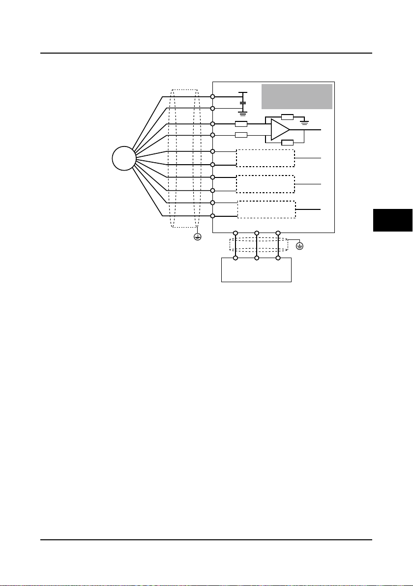
CN2
1 3
V
I
CN3
1 3
V
R
PE
AI4-
GND
AI4+ Analogueinput
-10-+10Vor
0-20mA
I/O card
AI4-
GND
AI4+
Wirejumpersetting
+5V
10k
CN2
1
3
V
I
CN3
1
3
V
R
PE
I/O card
Thermistor
4.5.2 I/O Card Wire Jumper Description
Table 4-6 Wire jumper function and setting description on the I/O card
Jumper Function and setting description Factory setting
AI4 analogue input channel can select voltage or current signal.
When pin 1 and pin 2 of the CN2 are short-circuited, AI4 channel
CN2
inputs voltage signal;
When pin 2 and pin 3 of the CN2 are short-circuited, AI4 channel
inputs current signal.
AI4 analogue input channel can select thermistor.
When pin 1 and pin 2 of the CN3 are short-circuited, AI4 channel is
for the user reference analogue input;
CN3
When pin 2 and pin 3 of the CN3 are short-circuited, AI4 channel is
for the motor over-heating detection signal input via the external
connected thermistor.
4.5.3 I/O Card Terminal Connection
Analogue input terminal connection
When the AI4 is used as the user reference analogue input terminal, the connection is shown as
Figure 4-18 and the AI4+ is as analogue input.
4
When the AI4 is used as the motor over -heating detection signal input terminal, the connection is
shown as Figure 4-19. The motor stator coil built-in thermistor to access the analog ue input and it
should be correctly set the wire jumper.
Digital input terminal connec ti on
The digital input terminals (DI7-DI12) of I/O card and the digital input terminals (DI1-DI6) of
contro l board have t he same connection method. Pl ease refer t o 4.4.4 Control Ter minal
Connection for details .
HD5L Series Controller User Manual ―27―
Figure 4-18 AI4 as the analogue input terminal
Figure 4-19 AI4 as the over-heating signal detection input terminal
Page 37

Chapter 4 Electri c al I ns tallation Shenzhen Hpmont Technology Co., Ltd
ON
000000:1 FD
ON
123123
FDlowbitFDhighbit
ON
000010:2*2 FD
ON
123123
ON
010000:16*2 FD
ON
123123
FDlowbitFDhighbit FDlowbitFDhighbit
4.6 Encoder Card
4.6.1 Encoder Cards Introduction
There are 4 kind encoder cards are provided for the HD5L series controller. And their models and
functions are shown as Table 4-7.
Table 4-7 Encoder card
Encoder cards Functions
OC encoder card with frequency
demultiplication (FD) output
(HD-PG2-OC-FD)
SINCOS encoder card with FD output
(HD-PG5-SINCOS-FD)
Line drive encoder card with FD
output(HD-PG6-UVW-FD)
SC encoder card with FD output
(HD-PG9-SC-FD)
The requirements of encoder card connec ti on:
1. Separate encoder card cables from power cables, and make sure they do not go parallel.
2. The encoder card cables must use independent tube and the metal enclosure must be reliable
grounded.
4.6.2 FD Description
To change the FD coefficient is by shift ing 6-digit FD switches. When the switch shifts to ON, it
will mean “1”, otherwise mean “0”. Converter the 6-digit binary number into decimal number, the
resulting number multiplies 2 is the FD coefficient shown as Figure 4-20.
Maximum value is “111111” which is 63*2 FD.
Support the differential ABZ signals and the pulse FD output;
Apply to asynchronous motor closed-loop vector control (VC)
Support the SINCOS signal and the pulse FD output;
Apply to synchronous motor closed-loop vector control (VC)
Support the differential ABZ and UVW signal;
Support the pulse FD output;
Apply to synchronous motor closed-loop vector control (VC)
Support the serial communication signal;
Support the pulse FD output;
Apply to synchronous motor closed-loop vector control (VC)
Figure 4-20 Encoder card FD description
―28― HD5L Series Controller User Manual
Page 38

Shenzhen Hpmont Technology Co., Ltd Chapter 4 Electri c al I ns tallation
1
6
11
5
15
10
24.5
50
27
ONON
1 2
3
1 2
3
32
Terminal
FDswitch
Toconnect
controlboard
A+PGP B+ OUTAPGP
A- OUTBCOM B- COM
FDlowbit
FDhighbit
4.6.3 DB15 Terminal
The HD-PG5-SINCOS-FD and the HD-PG6-UVW-FD both use the DB15 terminal. It will be well
to connect the DB15 terminal to the DB15 socket of motor encoder signal cable.
The definition of terminal number is shown as Figure 4-21.
Figure 4-21 DB15 terminal definition
4.6.4 HD-PG2-OC-FD
The OC encoder card with frequency demultiplication (FD) output is shown as Figure 4-22. FD
switch is sh o wn as the section 4.6.2 FD Description and the size unit is mm.
Figure 4-22 OC encoder card with frequency demultiplication output
Terminal description
Table 4-8 Terminal function description
Terminal Name Terminal Name
PGP +12V power output B+ Encoder B+ signal
COM
A+ Encoder A+ signal OUTA FD output A signal, NPN type OCoutput
A- Encoder A- signal OUTB FD output B signal, NPN type OCoutput
Power supply site,
isolated from GND
B- Encoder B- signal
4
HD5L Series Controller User Manual ―29―
Page 39

Chapter 4 Electri c al I ns tallation Shenzhen Hpmont Technology Co., Ltd
+ 5V
A
B
GND
Differential
output encoder
HD-PG2-OC-FD
PG interf ace card
Elevator controller
A+
A-
A+
A-
B+
B-
B+
B-
+12V
COM
COM
OUTA OUTB
PGACOM PGB
PGP
0V
VCC
COM
PE
PE
Interface circuit
the same as A
+ 5V
A
B
GND
A+
A-
A
B
B+
B-
+12V
COM
COM
OUTA OUTB
PGA PGB
PGP
0V
VCC
COM
COM
PE
PE
Open-collector
output encoder
Elevator controller
Interface circuit
the same as A
HD-PG2-OC-FD
PG interf ace card
Encoder card connection
The connection of differential output encoder and open-collector output encoder are respectively
shown as Figure 4-23 and Figure 4-24.
Figure 4-23 Connection of differential output encoder
―30― HD5L Series Controller User Manual
Figure 4-24 Connection of open-collector output encoder
Page 40
Shenzhen Hpmont Technology Co., Ltd Chapter 4 Electri c al I ns tallation
+ 5V
A
B
GND
A+
A-
A
B
B+
B-
+12V
COM
COM
OUTA OUTB
PGA PGB
PGP
0V
VCC
COM
COM
PE
PE
Push-pull
output encoder
Elevator controller
Interface circuit
the same as A
HD-PG2-OC-FD
PG interf ace card
The push-pull signal output encoder is shown as Figure 4-25.
4
HD5L Series Controller User Manual ―31―
Figure 4-25 Connection of push-pull output encoder
Page 41

Chapter 4 Electri c al I ns tallation Shenzhen Hpmont Technology Co., Ltd
No.
Name
Description
No.
Name
Description
30.5
55
6
DB15terminal
17
44
COM
OUTA
OUTB
ON
ON
1
2
3
1
2
3
FD
lowbit
FD
highbit
FDswitch
FDoutput
terminal
4.6.5 HD-PG5-SINCOS-FD
SINCOS encoder card with FD outpu t i s shown as Figure 4-26. FD switch is shown as the section
4.6.2 FD Description and the size unit is mm.
Terminal description
1 B- Differential signal B- 8 B+ Differential signal B+
2 NC Invalid 9 PGVCC +5V power supply
3 R+ Differential signal R+ 10 C+ Differential signal C+
4 R- Differential signal R- 11 C- Differential signal C5 A+ Differential signal A+ 12 D+ Differential signal D+
6 A- Differential signal A- 13 D- Differential signal D7 GND Power supply site 14、15 NC Invalid
No. Name Description
1 OUTA FD output signal A, NPN type OC output
2 OUTB FD output signal B, NPN type OC output
3 COM FD output signal site, isolated from GND
Figure 4-26 SINCOS encoder card with FD output
Table 4-9 DB15 terminal signal description
Table 4-10 FD output terminal signal description
―32― HD5L Series Controller User Manual
Page 42
Shenzhen Hpmont Technology Co., Ltd Chapter 4 Electri c al I ns tallation
+
-
PG
SINCOS enc oder
Elevator controller
Interface circuit
the same as A
Interface circuit
the same as A
Interface circuit
the same as A
HD-PG5-SINCOS-FD
PG interf ace card
Encoder card connection
The connection of SINCOS encoder is shown as Figure 4-27.
+5V
PGVCC
GND
A+
A-
B+
BC+
C-
D+
D-
PE
Figure 4-27 Connection of SINCOS encoder
COM
COM
GND
OUTA OUTB
PGA PGB
GND
A
B
C
D
PE
4
HD5L Series Controller User Manual ―33―
Page 43

Chapter 4 Electrical Installation Shenzhen Hpmont Technology Co., Ltd
No.
Name
Description
No.
Name
Description
30.5
55
6
DB15terminal
17
44
COM
OUTA
OUTB
ON
ON
1
2
3
1
2
3
FD
lowbit
FD
highbit
FDswitch
FDoutput
terminal
4.6.6 HD-PG6-UVW-FD
The line drive encoder card with FD output is shown as Figure 4-28. FD switch is shown as the
section 4.6.2 FD Description and the size unit is mm.
Figure 4-28 Line drive encoder card with FD output
Terminal description
1 A+ Differential signal A+ 9 V+ Differential signal V+
2 A- Differential signal A- 10 V- Differential signal V3 B+ Differential signal B+ 11 W+ Differential signal W+
4 B- Differential signal B- 12 W- Differential signal W5 Z+ Differential signal Z+ 13 PGVCC +5V power supply
6 Z- Differential signal Z- 14 GND Power supply site
7 U+ Differential signal U+ 15 NC NC
8 U- Differential signal U-
No. Name Description
1 OUTA FD output signal A, NPN type OC output
2 OUTB FD output signal B, NPN type OC output
3 COM FD output signal site, isolated from GND
Table 4-11 DB15 terminal signal description
Table 4-12 FD output terminal signal description
―34― HD5L Series Controller User Manual
Page 44
Shenzhen Hpmont Technology Co., Ltd Chapter 4 Electri c al I ns tallation
A
GND
PG
A+
A-
+5V
GND
OUTA OUTB
PGA PGB
PGVCC
B
B+
B-
Z
Z+
Z-
U
U+
U-
V
V+
V-
W
W+
W-
COM
COM
PE
PE
UVW encoder
Elevator controller
Interface circuit
the same as A
Interface circuit
the same as A
Interface circuit
the same as A
Interface circuit
the same as A
Interface circuit
the same as A
HD-PG6-UVW-FD
PG interf ace card
Encoder card connection
The connection of UVW encoder is shown as Figure 4-29.
4
Figure 4-29 Connection of UVW encoder
HD5L Series Controller User Manual ―35―
Page 45

Chapter 4 Electri c al I ns tallation Shenzhen Hpmont Technology Co., Ltd
DI7 DI8 PAO PBO R2A R2B R2C
P24
COM COM
R3A R3BSEL R3C
+5V C+ D+ A+ B+
GND C-
D- A- B-
4.6.7 HD-PG9-SC-FD
The serial communication encoder card with FD output suppo rted the Endat proto col is s hown as
Figure 4-30 and the size unit is mm.
Toconnectcontrolboard
Terrninal
65
5
105
95
5
Figure 4-30 Serial communication encoder card with FD output
Terminal description
Figure 4-31 Terminal signal description
Table 4-13 FD output terminal signal description
Item Terminal Name Function Description
Programmable bipolar optional input signal
Digital input DI7-DI8 Digital inp u t 7-8
FD output
Relay output
Power
Power
Signal
Terminal
PAO
PBO FD output signal B, NPN type OC output
R2A/R2B/R2C
R3A/R3B/R3C
P24
SEL
COM
+5V +5V power +5V power supply for PG
GND
C+/C- CLK CLK Differential signal C+/CD+/D- Data Data Differential signal D+/D-
A+/A-/B+/B- Sin/Cos Signal Differential signal A+/A-/B+/B-
FD output
Relay contact
output
+24V power
supply
Digital input
common
terminal
Digital reference
ground
+5V reference
ground
Input voltage: 0-30VDC
Input impedance: 4.7kΩ
FD output signal A, NPN type OC output
Programmable output, contact rating: 250VAC/3A or
30VDC/1A
RB,RC: normally closed; RA,RC: normally open
Digital in p u t use +24V as supply, max imum output current
is 200mA
Factory settings default SEL and P24 are connected.
Disconnected SEL and P24 when use external power to
drive DI7-DI12
Digital site, isolated from CME
+5V reference ground
FD description
The FD coefficient of serial communication encoder card with FD output is set by F16.10.
―36― HD5L Series Controller User Manual
Page 46

Shenzhen Hpmont Technology Co., Ltd Chapter 4 Electri c al I ns tallation
Mainspowersupply
4.7 Meet EMC Requirement of Installation
4.7.1 Correct EMC Installation
According national standards GB/T12668.3, the controller should meet the two requirements of
electromagnetic interference (EMI) and anti-electromagnetic interference. The international
standards IEC/61800-3 (VVVF drive system part 3: EMC specifications and test methods) are
identical to the national standards GB/T12668.3.
HD5L Series Controllers are designed and produced according to the requirements of
IEC/61800-3. Please install the controller as per the description below so as to achiev e good
electromagnetic compatibility (EMC).
In a drive system, the controller, control equipment and sen sors are installed in the sa me cabine t,
the electromagnetic noise should be suppressed at the main connec tin g points w ith the EMI filter
and input reactor installed in cabinet to satisfy the EMC requirements.
The most effective but ex pensive measure to r educe the interfere nce is to iso late the no ise
source and the noise receiver, which should be considered in mechanical system design phase.
In driving system, the noise source can be controller, braking unit and contactor. Noise receiver
can be automation equipment, encoder and sensor etc.
The mechanical/system is divided into different EMC areas according to its electrical
characteristics. The recommended installation positions are shown in Figure 4-31.
4
Powersupplycontrolcabinet
Manufacturemachines
AreaA
Controldevices(the
hostPC, PLCetc.)
AreaB
Sensor(temperature,
liquidlevelsensor)
Mechanicalsystem
AreaE
AreaC
ACreactor
EMIfilter
HD5Lcontroller
AreaD
EMIfilter
AreaF
Motor
Figure 4-31 System wiring sketch
AreaA:installtransformersofcontrolpowersupply,
controldevicesandsensoretc.
AreaB:interfacesofsignalandcontrolcables,
correctimmunitylevelisrequired.
AreaC:installnoisesourcessuchasinputreactor,
thecontroller,brakingunitandcontactor.
AreaD:installoutputEMIfilterand itscable
nparts.
connectio
AreaE:powersupply.
AreaF:installmotoranditscables.
Earthisolatedboard
HD5L Series Controller User Manual ―37―
Page 47

Chapter 4 Electri c al I ns tallation Shenzhen Hpmont Technology Co., Ltd
Motorcables
>30cm
>20cm
>50cm
Powercables
Signal/controlcables
Powerormotorcables
Signal/controlcables
Enclosure
PE
PE
Enclosure
Remarks:
• All areas sho uld be isolated in sp ace to achieve electromagnetic decoupling effect.
• The minimum distance between areas should be 20cm, and use earthing bars for decoupling
among areas, the cables from different area should be placed in different tubes.
• EMI filters should be installed at the interfaces between different areas if necessary.
• Bus cable (such as RS485) and signal cable must be shielded.
4.7.2 Wiring Requirement
In order to avoid interference intercoupling, it is recommended to sepa rate the motor cables and
the control cables from power supply cables, and keep enough distance among the cables.
Especially when the cables are laid in parallel and the cable length is long, the signal cables
should cross the power supply cables perpendicularly as shown in Figure 4-32.
4.7.3 Wiring Motor
―38― HD5L Series Controller User Manual
Figure 4-32 System wiring
Shielded/armoured cable: High frequency low impedance shielded cable should be used. For
example: copper net, aluminum net or iron net.
Normally, the control cables mus t use the shielded ca ble s and the shieldi ng metal net must be
connected to the metal enclosure of the controller by cable clamp s as shown in Figure 4-33.
Figure 4-33 Correct connection of the shielded cable
Longer the cable between the controller and the motor is, higher the high-frequency leakage
current is, causing the controller output current to increase as well. This may affect peripheral
devices.
When the cable between the motor and the controller is longer than 100 meters, it is
recommended to install output reactor and adjust the carrier frequency as per the instruc tion in
Table 4-14.
Page 48

Shenzhen Hpmont Technology Co., Ltd Chapter 4 Electri c al I ns tallation
HD5L
Dedicatedearthingpole
(optimal)
PE
PE
Sharingearthingpole
(good)
HD5LOtherdevices Otherdevices
PE
PE
HD5L HD5LOtherdevices
Otherdevices
Sharingearthingpole
(notsogood)
Prohibitedearthingmethod
PE
PEPE PE
HD5L HD5L HD5L HD5L
Table 4-14 Carrier frequency and the cable length between controller and motor
Cable length
Carrier frequency 15kHz below 10kHz below 5kHz below 2kHz below
< 30m 30-50m 50-100m ≥ 100m
The controller should be der ated if the motor cables are too long or their cross sectional area
(CSA) is too large. The controller’s cables should be the cable s w ith specified CSA (see Table 4-1)
because the capacitance of the cable to ground is in proportional to the cable’s CSA. If the cable
with big CSA is used, its current should be reduced. The current should be decreased by 5%
when per level of CSA is increased.
4.7.4 Ground Connections
The earth terminals PE must be connected to earth properly. The earthing cable should be as
short as possible (the earthing point should be as close to the controller as possible) and the
earthing area should be as large as possible.
The grounding resistance should be less than 10Ω.
Do not share the earth wire with other dev ices such as welding machines or power tools. It could
share the earthing pole, but the motor and the controller each have their own earthing pole, then
the earthing effect is better. The recomme nded and avoided earthing methods are respectively
shown in Figure 4-34 and Figure 4-35.
4
Figure 4-34 Recommended earthing method
Figure 4-35 Avoided earthing method
When using more than one controllers, be careful not to loop the earth wire as shown in Figure
4-36.
Figure 4-36 Prohibited earthing method
4.7.5 EMI Filter
The EMI filter s hould be used in the equipment that may generate strong EMI or the equipment
that is se nsitive t o t he extern al EMI. The EMI filter should be a dual-way low pass filter through
which lower frequency current can flow while higher frequen cy current ca n hardly flow.
HD5L Series Controller User Manual ―39―
Page 49

Chapter 4 Electri c al I ns tallation Shenzhen Hpmont Technology Co., Ltd
Function of EMI filter
1. The EMI filter ensures the equipment not only can satisfy the conductin g emission and
conducting sens itivity i n EMC standar d but also can suppress the radiation of the equipment.
2. It can prevent the EMI generated by equipment from entering the pow er cable and the EMI
generated by power cable from entering equipment.
Common mistakes in using EMI filter
1. Too long the power cable is between the EMI filter and the controller
The filter inside the cabinet should be located near to the input power source. The length of the
power cables should be as short as possible.
2. Too close the input and output cables of the EMI filter
The distance between input and output cables of the filter should be as far apart as possible.
Otherwise the high-frequency noise may be coupled between the cables and bypass the filter.
Thus, the fi lter will become ineffective .
3. Bad eart hing of the EMI filter
The EMI filter’s enclosure must be earthed properly to the metal case of the controller. In order to
achieve better earthing effect, make use of a special earthing termin al on the filter’s enclosure . If
you use one cable to connect the filter to the case, the earthing is useless for high freque ncy
interference. When the frequency is high, so is the impedance of cable, hence the re is little
bypass effect.
The correct installation: The filter should be mounted on the enclosure of equipment. Ensure to
clear away the insulation paint between the filter case and the enclosure for good earthing
contact.
4.7.6 Conduction, Radiation and Radio Frequency Interference
Countermeasures
EMI of the controller
The controller’s operat ing theory m eans that s ome EMI is unav oidable. The controller is usually
installed in a metal cabinet which normally little affects the instruments out side the metal cabinet.
The cables are the main EMI source. If connect the cables according to this manual, the EMI can
be suppressed effectively.
If the controller and other control equipment are installed in one cabinet, the area rule must be
observe d. Pay attention to the isolation between different areas, cable layout and shielding .
Reducing conducted interfer e nce
Please add a noise filter to suppress conducted interference on the outpu t side. Additionally,
conducted interference can be efficiently red uced by threading all the output cables through a
grounded metal tube. And condu c ted inter ferenc e can be dra ma tically decreased when the
distance between the output cables and the signal cables is above 0.3m.
RF interference clearing
The I/O cables an d the controller produce radio frequency interference. A noise filter can be
installed both on the input side and output side, an d shield them with iron utensil to reduce RF
interference.
―40― HD5L Series Controller User Manual
Page 50

Shenzhen Hpmont Technology Co., Ltd Chapter 4 Electri c al I ns tallation
HD5L
EMIfilter
X
X
X
MCCB
M
Ironbox
Metaltube
~
EMIfilter
The wiring distance between the controller and the motor should be as short as po ssi ble shown in
Figure 4-37.
Figure 4-37 RF interference clearing
4.7.7 Input and Output Reactor
AC input reactor
The purpose of installing an AC input reactor is: to increase the input power factor; to dramatically
reduce the harmonics on the input side at the high voltage poin t of common coupling and prevent
input current unbalance which can be caused by the phase-to-phase unbalan ce of the power
supply. An AC line reactor which will help to protect the input rectifiers also reduces e xternal li ne
voltage spikes (for example the lightning!).
DC reactor
The installation of a D C reactor can increas e the input power fact or, improve the controller’s
overall efficiency and thermal stability, substantially eliminate the upper harmonics influence on
the controller’s performance, and considerably decrease the conducted and radiated
electromagnetic emissions from the controller.
AC output reactor
Generally speaking, when the length of the cable between controller and motor is more than
100m, it will cause leakage current and controller tripping. It suggests that the user should
consider installing an AC output reactor.
4
HD5L Series Controller User Manual ―41―
Page 51

Page 52

Shenzhen Hpmont Technology Co., Ltd Chapter 5 Operation Instructions
Danger
Warning
RUN
STOP
Chapter 5 Operation Instructions
• Only when the controller terminal cover has been fitted can you switch on AC power source. Do not
remove the cover after power is switched on.
• Ensure the motor and the mechnical device are in the use application before the controller starts.
• Keep away from the controller if the auto-restart function is enabled at power outage.
• If changed the main control PCBA, you should correctly set the parameters before operating.
• Do not check or detect the signal during the controller operation.
• Do not randomly change the controller parameter setting.
• Please thoroughly complete all control debugging and testing, make all adjustments and conduct a full
safety assessment before switching the run command source of the controller.
• Do not touch the energy-depletion braking resistor due to the high temperature.
5.1 Function Descri pt ion
Note:
1. In the following sections, you may encounter control, runni ng and state of the controller
description many times.
2. Please read this section carefully. It will help you to correctly understand and use the functions
to be discussed.
5.1.1 Operation Mode
The operation mode defines how the controller recei ves run com mands (start or stop command).
There are four operation modes which can be selected through function parameter F00.05.
Panel control: The run command is controlled by and keys of the panel; and the
run speed is set by F00.07.
Terminal analogue control: The run command is controlled by UP and DN of the terminal; and
the run speed is set by AI1-AI4 analogue input terminals.
Terminal speed control: The run command is controlled by UP and DN of the terminal; and the
run speed is set by MS1-MS3 multi-s tep speed ter min al combination.
Communication speed control: The run command and the run multi-step speed are set by PC
communication.
5
HD5L Series Controller User Manual ―43―
Page 53

Chapter 5 Operation Instructions She nzhen Hpmont Technology Co., Ltd
STOP
RUN
RUN
5.1.2 Control Mode
HD5L series controllers have three control modes which respectively are V/f control, SVC control
and VC control. (Refer to F00.01 for more detail)
5.1.3 Controller State
HD5L series controller states respectively are: Stop, Run, Motor parameters auto-tuning, Fault
alarm and Under-voltage.
Stop state: After the controller is switched on and initialized, if no run command inp uts or the
stop command is given, there will be no output from U/V/W of the controller and the LCD panel
will be anti-color display under the left.
Run state: The controller will start output from U/V/W terminals after it receives the run
command. And the LCD panel will be anti-color display under the left.
Motor parameters aut o-tuning: After set the function parameter F07.06/F10.10 as 1 or 2, the
controller will receive the run command then enter into motor parameters auto-tuning state. If the
auto-tuning process is compl et ed, th e controller will enter into stop sta te.
Fault alarm state: The controller has failure.
Under-voltage state: The controller is in the under-voltage.
5.1.4 Controller Running Mode
HD5L series controllers have five running modes: Auto-tuning running, MS speed running,
Inspection running, Battery-driven running and Normal running.
Auto-tuning running: Set F07.06/F10.10 = 1 or 2 and press key to enter the auto-tuning
running.
MS speed running: The run speed is set by MS1-MS3 in combination or communication. This
mode is acc essible when F00.05 is set as 2 or 4.
Inspection running: When inspection signal is valid, the speed will be determined by F05.08
(inspection run speed). This mode is accessible when F00.05 is set as 1, 2 or 4.
Battery-driven running: When emergency signa l is valid, the speed will be determined by
F05.09 (battery driven speed). This mode is accessible when F00.05 is set as 1, 2 or 4.
Normal running: Controlled by panel (F00.05 = 0) or terminal analogue (F00.05 = 1).
―44― HD5L Series Controller User Manual
Page 54

Shenzhen Hpmont Technology Co., Ltd Chapter 5 Operation Instructions
ENTSHF
JOGPRG
STOPRUN
PRG
JOG
RUN
STOP
5.2 Operating Instructions
5.2.1 Panel Description
The standard HD5L series controllers are installed with LCD panel which is shown as Figure 5-1.
5
Figure 5-1 Panel of HD5L controller
There are keys on the panel and their functions, as shown in Table 5-1.
Table 5-1 Key function description
Key Name Function
Program/exit Entry or exit programming key
Jog key Reserved
Run key In the mode of panel control, press this key to run the controller
Stop/reset key In the mode of panel control, to stop controller and reset the fault
Multi-function key Set certain function by F00.06
Increment key Increase value or parameter
Decrement key Decrease value or parameter
SHF shift key Selecting display parameter and shift bit
ENT enter/confirm key Enter lower menu or confirm saving the data
HD5L Series Controller User Manual ―45―
Page 55

Chapter 5 Operation Instructions She nzhen Hpmont Technology Co., Ltd
STOP
RUN
F03:
0.3 5 0 m/s
0.3 5 0 m/s
RUN
Ready pa ra.
Setti ng s peed
=0 1. 5 0 0 m/s
ALMSTOPUP LO/ RE
Runni ng p ara.
Given sp eed
=0 1. 3 5 9 m/s
ALM
RUNUP LO/RE
5.2.2 Display State
The panel of HD5L series controller can display the parameters at stopping, running, editing and
alarming.
Note:
LCD anti-color displays: display in white on black such as , , , etc.
1. If the parameter or the setting value is in anti-color displaying, it means that it can be changed.
Take for example, it m eans that the units of setting value can be changed.
2. If the state is in anti-color displaying, it means that it is in thi s s tate. Take for example, it
means that the controller is in the run ning state.
Parameter display state at stopping
When the controller stops runn ing, the pan el will dis play stopp ing state and its par ameter, as
shown in Figure 5-2. Other parameters (F15.08-F15.13) can be displayed by pressing .
Figure 5-2 Display state of the panel
Parameter display state at running
When the controller is running, the panel will display running state and its parameter , a s s hown in
Figure 5-2. Other parameters (F15.02-F15.07) can be displayed by pressing .
Four-level menu switching operation
The panel of HD5L series controller uses fou r -level menu configuration for parameter setting or
other operations.
Configuring mode can be displayed in 4-le vel menu : mode setting (first-level)→function
parameter group setting (second-level)→function parameter setting (third-level)→parameter
setting (fourth-level). The operation process is shown in Figure 5-3 and the description of the
keys is shown in Table 5-2.
―46― HD5L Series Controller User Manual
Page 56
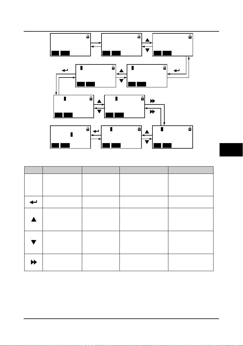
Shenzhen Hpmont Technology Co., Ltd Chapter 5 Operation Instructions
F:
Genera l fun ction par a
用户密 码
ALMSTOPUP LO/RE
Ready pa ra.
Setti ng s peed
=0 1. 5 0 0 m/s
ALMSTOPUP LO/RE
D:
Displ ay P ara.
菜单模 式
ALM
STOPUP LO/ RE
F03:
Acc/D ec p aram eters Basic pa rame ters
Acc s peed
用户密 码
ALMSTOPUP LO/RE
F00:
用户密 码
ALMSTOPUP LO/RE
Dec s peed
菜单模 式
ALMSTOPUP LO/RE
F03.0 0:
用户密 码
ALMSTOPUP LO/RE
F03.0 3:
= 0 0 .3 5 0 m/s
3
F03.0 3:
Dec s peed
菜单模 式
ALMSTOPUP LO/RE
F03.1 3:
Stop Dec jerk
菜单模 式
ALMSTOPUP LO/RE
F03.1 3:
Stop Dec jerk
ALMSTOPUP LO/RE
PRG
PRG
PRG
PRG
PRG
meters
Stop state
Second-level menu
First-level menu
First-level menu
Second-level menu
Third-level menu Third-level menu
Third-level menu
Third-level menu
Fourth-level menu
PRG
Key First-level menu Second-level menu Third-leve l me n u Fourth-le ve l me nu
Fault, return to faulty
display; Fault
cleared, return to run
or stop state display.
Enter to second-level
menu
Select function
group.
HD5L Series Controller User Manual ―47―
Cycle according to
D-F- Y
Select function
group.
Cycle according to
Y-F-D
Invalid Invalid Switch units and tens
Figure 5-3 Four-level operation process
Table 5-2 Switching four-level description of the key
Return to first-level
menu
Enter to third-level
menu
Modify No. function.
Increase by 1 when
press this key one
time
Modify No. function.
Decrease by 1
when press this key
one time
Return to second-level
menu
Enter to fourth-level menu
Modify the internal No. of
function group. Increase
by 1 according to the
present modified bit
Modify the internal No. of
function group. Decrease
by 1 according to the
present modified bit
Do not save the present
value and return to
third-level
Save the present value
and return to third-level
Modify function value.
Increase by 1 according
to the present modified
bit
Modify function value.
Decrease by 1
according to the present
modified bit
Switch units , ten
thousands, thousands,
hundreds, tens
5
Page 57

Chapter 5 Operation Instructions She nzhen Hpmont Technology Co., Ltd
PRG
F03:
Acc/D ec p aram eters
用户密 码
ALMSTOPUP LO/ RE
= 0 0 .3 5 0 m/s
3
F03.1 3:
Stop Dec jerk
ALMSTOPUP LO/ RE
ALM
Lu:
DC bu s l ow
ALM
STOPUP LO/ RE
请按键 以检 测其 有效 性
E0024 :
Exter nal faulty
ALMSTOPUP LO/RE
请按键 以检 测其 有效 性
STOP
= 0 1 .5 0 0 m/s
F00.0 7:
ALM
STOPUP LO/ RE
F00.0 7:
Spee d s ett ing of pa ne
l菜单 模式
ALMSTOPUP LO/RE
= 0 1 .5 0 0 m/s
F00.0 7:
ALMSTOPUP LO/RE
Shifting
= 0 1 .0 0 0 m/s
F00.0 7:
ALMSTOPUP LO/RE
Modify setting value
Basic pa rameters
F00:
运行方 向选 择
ALMSTOPUP LO/RE
F00.0 8:
Run d irec tion
菜单模 式
ALMSTOPUP LO/RE
F:
Genera l fun ction par a
meters
ALM
STOPUP LO/ RE
Ready pa ra.
Setti ng s peed
=0 1. 0 0 0 m/s
ALMSTOPUP LO/RE
PRGPRG
PRG
Stop stateFirst-level menu
Second-level menu
Third-level menu
Fourth-level menu
Third-level menu
Function parameter editing stat e
At stop, run or fault alarm state, press to enter function param et er edi tin g state (see the
description of parameter F01.00 and the user password unlock and modify of section 5.2.3), as
shown in Figure 5-4.
Figure 5-4 Parameter editing state
Fault alarming state
If the controller detect s a fault signal , the panel will enter the fault alarming state and LCD wil l
display the fault code and name and anti-color display , as shown in Figure 5-5.
Y ou can enter Group F17 to check the fault history.
Figure 5-5 Fault alarming state
The controller can be reset by pressing key, or by sending the reset commands via the
external terminal or communicatio n reset command.
5.2.3 Panel Operation Examples
Function parameter setting
For example: To modify the setting value of the function parameter F00.07 from 1.500m/s to
1.000m/s, as shown in Figure 5-6.
―48― HD5L Series Controller User Manual
In the setting fourth-level menu situation, if the parameter is not in anti-color displaying, it
indicates that this parameter can’t be modified. The possible reasons are as follows:
Figure 5-6 Function parameter setting
Page 58
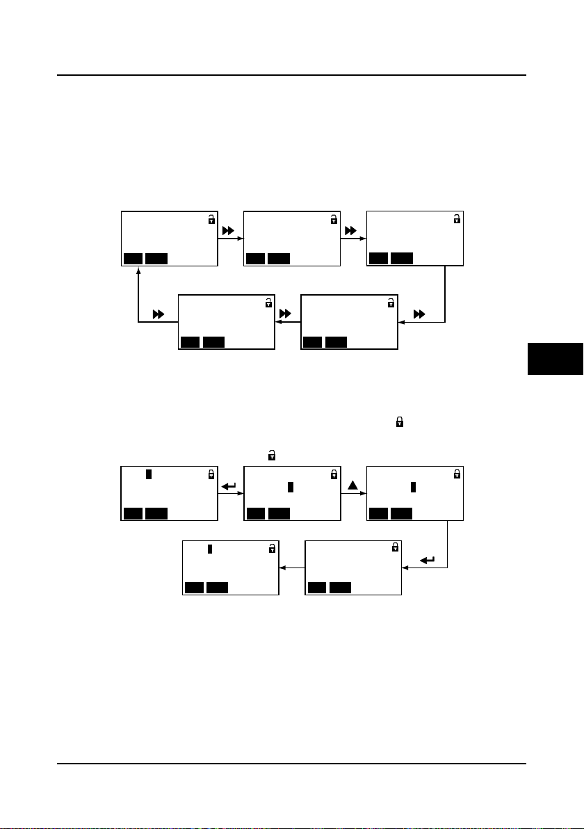
Shenzhen Hpmont Technology Co., Ltd Chapter 5 Operation Instructions
Ready pa ra.
Setti ng s peed
=0 1. 5 0 0 m/s
ALMSTOPUP LO/RE
F15.08 = 4
Ready pa ra.
DC bu s vo ltag e
=0 1. 5 3 7 V
ALM
STOPUP LO/ RE
F15.09 = 14
Ready pa ra.
AI1 v olta ge d isposal
=0 1. 6.0 0 V
ALM
STOPUP LO/ RE
F15.10 = 16
Ready pa ra.
Output ter minal sta te
=0000 00 00 0000 0000
ALMSTOPUP LO/RE
F15.12 = 27
Ready pa ra.
Input te rminal state
=0000 00 00 0000 0000
ALM
STOPUP LO/ RE
F15.11 = 26
F01.0 0
=0 0 0 0 4
User pas sword
ALMSTOPUP LO/RE
F01.0 0
User pas sword
菜单模 式
ALMSTOPUP LO/RE
F01.0 0
=0 0 0 0 0
User pas sword
ALMSTOPUP LO/RE
F01.0 1
Menu mod e
菜单模 式
ALMSTOPUP LO/RE
Unloc k su cces s
ALMSTOPUP LO/RE
Third-level menu
Unlock success
Fourth-level menu Input correct password
Third-level menu
• The function parameter can’t be modified, such as the actual detected parameters or recorded
parameters etc.
• Only when the controller stops can it modify the function parameter.
• Only input the correct password can it edit the function parameter due to the valid password.
Switching display parameters at stopping s t a te
There are six stopping parameters(F15.08-F15.13) of the HD5L controller. For example, set the
parameter to be default value and the Figure 5-7 describes the operation of displaying
parameters.
Figure 5-7 Switching display parameters at stopping state
Unlock user’s passwo rd
When user set F01.00 to non-zero value and detect no pres s on the panel within 5 minutes, th e
user’s password will be valid. The lock identification of panel will be .
The operation of unlock user’s password is as shown in Figure 5-8 which takes 4 as the user’s
password. The lock identification will be when it successfully unlocks.
Figure 5-8 Operation of unlocking user’s password
HD5L Series Controller User Manual ―49―
5
Page 59
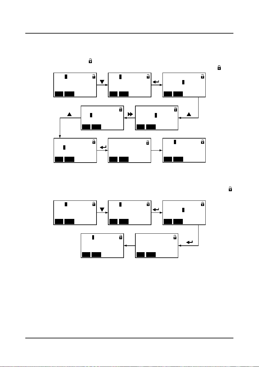
Chapter 5 Operation Instructions She nzhen Hpmont Technology Co., Ltd
F01.0 0
=0 0 0 0 0
User pas sword
ALMSTOPUP LO/RE
F01.0 1
Menu mod e
菜单模 式
ALMSTOPUP LO/RE
F01.0 0
User pas sword
菜单模 式
ALMSTOPUP LO/RE
F01.0 1
Menu mod e
菜单模 式
ALMSTOPUP LO/RE
PW. has been cleared
菜单模 式
ALMSTOPUP LO/RE
Clear password
Third-level menu Fourth-level menu
Third-level menu
Third-level menu
Modify user’s passw o rd
If no password, directly modify the value of F01.00 according to Figure 5-9.
If there is password, you should unlock the password according to Figure 5-8. When the lock
successfully displays the , you can set a new password according to Figure 5-9 which takes
“02004” as the new password. When the password is valid, the lock identification will be .
F01.0 1
User pas sword
菜单模 式
ALMSTOPUP LO/RE
Third-level menu
F01.0 0
= 0 0 0 0 4
User pas sword
F01.0 0
= 0 2 0 0 4
User pas sword
ALMSTOPUP LO/RE
Modify password thousands Modify successfully
Figure 5-9 Operation of modifying user’s password
F01.0 0
User pas sword
菜单模 式
STOPUP LO/ RE
Third-level menu Fourth-level menu
ALMSTOPUP LO/RE
Shifting Modify password units
Encry ptio n su ccess
菜单模 式
ALM
F01.0 0
=0 0 0 0 4
User pas sword
ALMSTOPUP LO/RE
F01.0 0
=0 0 0 0 0
F01.0 1
User pas sword
ALMSTOPUP LO/RE
Menu mod e
菜单模 式
Third-level menu
ALMSTOPUP LO/RE
ALMSTOPUP LO/RE
Clear use r’s password
If there is passw o r d , y ou should unlock according to Figure 5-8. When it successfully displays ,
you can clear the user’s password according to Figure 5-10.
Figure 5-10 Operation of clearing user’s password
―50― HD5L Series Controller User Manual
Page 60

Shenzhen Hpmont Technology Co., Ltd Chapter 5 Operation Instructions
Pleas e pr ess the key
STOPR UN
PRG
UP
DN
JOG
SHIFT
M
ENTER
Pleas e pr ess the key
STOPR UN
PRG
UP
DN
JOG
SHIFT
M
ENTER
Pleas e pr ess the key
STOPR UN
PRG
UP
DN
JOG
SHIFT
M
ENTER
Pleas e pr ess the key
STOPR UN
PRG UP
DN
JOG
SHIFT
M
ENTER
Pleas e pr ess the key
STOPR UN
PRG UP
DN
JOG
SHIFT
M
ENTER
Pleas e pr ess the key
STOPR UN
PRG
UP
DN
JOG
SHIFT
M
ENTER
Pleas e pr ess the key
STOPR UN
PRG UP
DN
JOG
SHIFT
M
ENTER
Pleas e pr ess the key
STOPR UN
PRG UP
DN
JOG
SHIFT
M
ENTER
Panel se lf-test pass
STOPR UN
PRG UP
DN
JOG
SHIFT
M
ENTER
JOG
PRG
STOP
RUN
Panel self-testing
The panel of the HD5L series controller has self-testing fu n ction whi ch facilitates periodic
inspection for itself and the keys.
The process of panel self-testing:
1. In stoppi ng s tate, pres s key and key simultaneously for 2-3 seconds, the panel will
check the LCD whether works well which is as show n in Figure 5-11.
2. Press any key of the pane l and if the state is in anti-color display, it means the key is valid. And
the corr ec t correspondence is as shown in Figure 5-12.
During this process, if there is no press in 4-5 seconds, it will directly jump to the step 4. If the
self-check is success, it will jump to the step 3.
3. If all keys are valid, the panel will display “Panel self-test pass”. The “Panel self-test pass” will
auto-disappear within 3-5 seconds and back to display state before self-testing.
4. If the key is invalid, the correspondence display will not be in anti-color displaying. The panel
will display “Panel self-test fail”. The “Panel self-test fail” will auto-disappear within 3-5 seconds
and back to display state before self-testing.
The possible reasons of self-testing failure: no press within 5s or invalid key.
Figure 5-11 Starting panel self-testing
Figure 5-12 Correct correspondence of the keys and the displays
5
HD5L Series Controller User Manual ―51―
Page 61

Chapter 5 Operation Instructions She nzhen Hpmont Technology Co., Ltd
Para . being up loa ded
Uploa d pr ogre ss:
050%
=0 1. 5 0 0 m/s
停机状 态参 数
Dnloa d fa il
=0 1. 5 0 0 m/s
ALMSTOPUP LO/RE
Para . being dn loa ded
Dnloa d pr ogre ss
:030%
=0 1. 5 0 0 m/s
HpmontTechnology
Lu:
DC bu s lo w
ALMSTOPUP LO/ RE
Ready pa ra.
Setti ng s peed
= 1. 5 0 0 m/s请按键 以检 测其 有效 性
ALMSTOPUP LO/ RE
Upload and download parameters
Upload: W hen set the f unction pa rameter F01.03 = 1, it uploads the setting value to the panel.
When the up load is fin ished, the panel will jump to dis play F01.00.
Download: When set the function parameter F01.02 = 2, it downloads the setting value from the
panel. When the download is finished, the panel will jump to display F01.03.
The upload and download parameters are as shown in.
Figure 5-13 Display upload and download parameters
Note:
1. When downloading parameters, it displays “dFAiL” which represents that the EEPROM
storage parameters of panel and the function parameters of present controller do not match.
First, you need upload the setting value of the correct function code to the EEPROM of panel,
and then you can download.
2. When upload or download parameters, the panel displays “E0022” (panel EEPRO M faul t) . It
will jump to next function code 10 seconds later. The troubleshooting is in Chapt er 8 (Page 99).
5.3 Initial Power On
It need carefully check before power is on. Please wire the controller according to the
specifications supplied by this manual.
After checking the wiring and mains supply voltage, switch on the circuit breaker and the
controller will be initialization. The panel will display as shown in Figure 5-14.
Figure 5-14 Display initialing panel
―52― HD5L Series Controller User Manual
Page 62

Shenzhen Hpmont Technology Co., Ltd Chapter 6 Function Introduction
Chapter 6 Function Introduction
This chapter will provide user with detail function introduction of each group.
Display Parameters:
Group D00 System State Parameters (on pages 54-55)
Group D01 D rive State Paramet ers (on pages 55-55)
Group D02 Analogue State Display Pa rameters (on pages 56-57)
Group D03 Running State Parameters (on pages 57-58)
Group D04 Encoder State Parameters (on pages 58-59)
General Function Parameters :
Group F00 Basic Parameters (on pages 59-61)
Group F01 Protection of Parameters (on pages 61-62)
Group F02 Start & Stop Parameters (on pages 62-63)
Group F03 Acceleration/Deceleration Parameters(on pages 63-64)
Group F04 Analogue Curve Parameters (on pages 64-65)
Group F05 Speed Parameters (on pages 65-67)
Group F06 Weighing Compensation Parameters (on pages 67-68)
Group F07 Asynchronous Motor Parameters (on pages 68-71)
Group F08 Motor Vector Control Speed-loop Parameters (on pages 71-72)
Group F09 Current-loop Parameters (on pages 72-72)
Group F10 Synchronous Motor Parameters (on pag es 72-73)
Group F11 PG Parameters (on pages 73-74)
Group F12 Digital I/O Terminal Parameters (on pages 74-77)
Group F13 Analogue I/O Terminal Parameters (on pages 77-79)
Group F14 SCI Communication Parameters (on pages 79-79)
Group F15 Display Control Parameters (on pages 79-81)
Group F16 Enhance Function Parameters (on pages 81-82)
Group F17 Fault Protect Parameters (on pages 82-85)
Group F18 PWM Parameters (on pages 85-85)
Group F19 Reserved
Group F20 Reserved
Manufacturer Function Paramet ers ( on pa ge 85)
6
HD5L Series Controller User Manual ―53―
Page 63
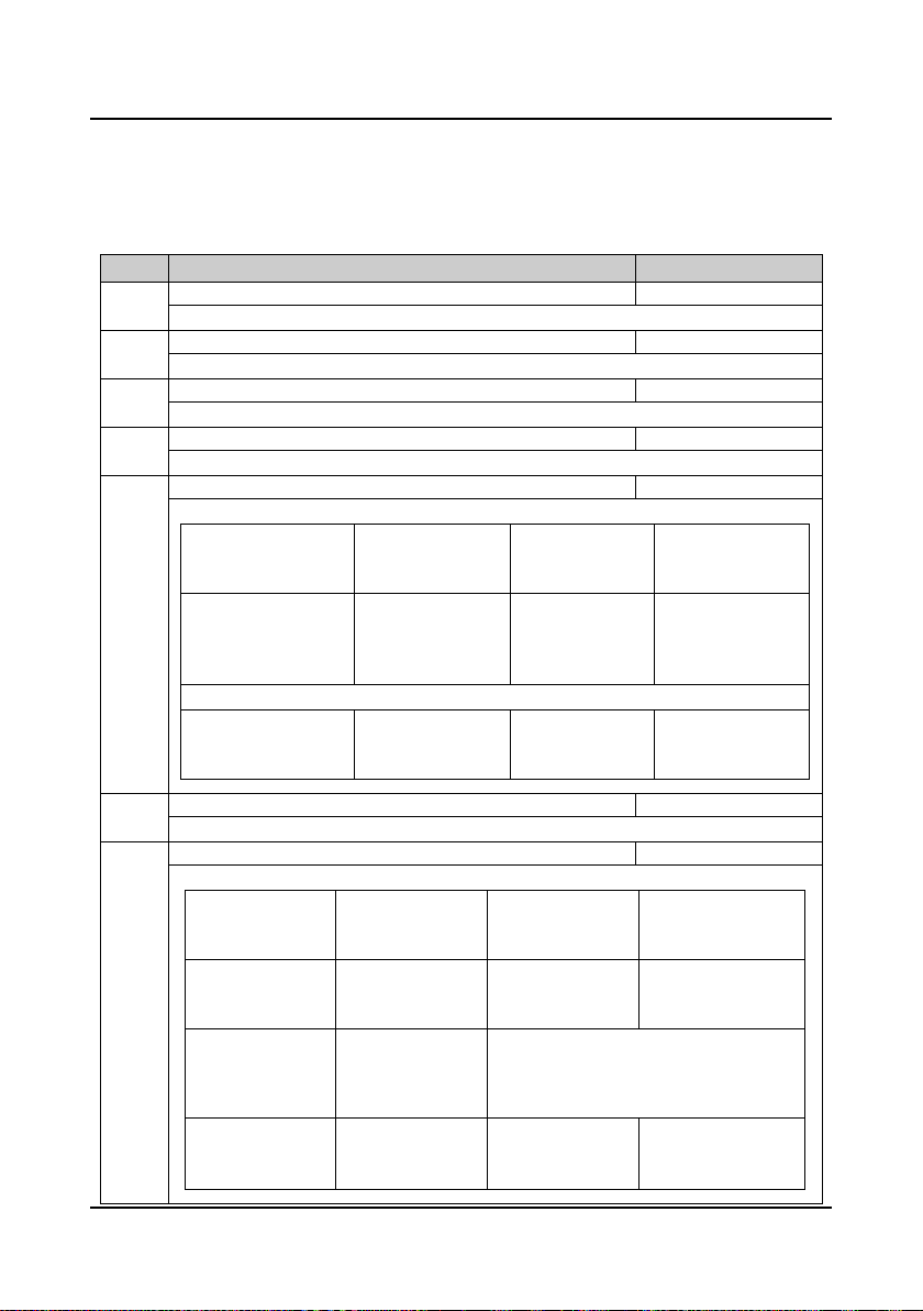
Chapter 6 Functi on Intr oduc ti on Shenzhen Hpmont Technology Co., Ltd
【
【
【
【
【
123
D00.05
Controller rated current
【actual value】
D00.06
Controller state
【actual value】
123
6.1 Group D: Display Parameters
Group D is st ate displ ay paramet ers. The users can directly che ck the state p arameter s b y
checking the function code of Group D.
6.1.1 Group D00 System State Parameters
Code Name Description Range【factory setting】
D00.00 Controller series
Display HD5L controller series.
D00.01 DSP software version
Display the DSP software version.
D00.02 DSP special software version
Display the DSP special software version.
D00.03 Panel software version
Display the panel software version.
D00.04 Elevator running state
Display the elevator running state in 16-bit binary. As following:
Bit15: battery driven run
0: no
1: yes
Bit11: down forced Dec.
input
0: invalid
1: valid
Bit7-bit4: reserved which means “0”
Bit3: analogue run
0: no
1: yes
Bit14: MS terminal 3
0: invalid
1: valid
Bit10: up forced Dec.
input
0: invalid
1: valid
Bit2: MS run
0: no
1: yes
Bit13: MS terminal 2
0: invalid
1: valid
Bit9: contactor
feedback input
0: invalid
1: valid
Bit1: inspection run
0: no
1: yes
actual value】
actual value】
actual value】
actual value】
actual value】
Bit12: MS terminal 1
0: invalid
1: valid
Bit8: brake feedback
input
0: invalid
1: valid
Bit0: controller enable
0: disenable
1: enable
Display the controller rated current.
Display the controller state in 16-bit binary. As follo win g:
―54― HD5L Series Controller User Manual
Bit15: reserved Bit14: reserved
Bit11: brake output
0: invalid
1: valid
Bit7: run at
zero-speed
0: not at zero-speed
1: at zero-speed
Bit3: DN
0: no
1: yes
Bit10: ready to run
0: not ready
1: be ready
Bit6: zero-speed
signal
0: invalid
1: valid
Bit2: UP
0: no
1: yes
Bit13: stop signal
0: no stop signal
1: stop signal
Bit9: speed arrived
0: no
1: yes
Bit5&Bit4: acceleration/deceleration/constant
00: constant
11: reserved
Bit1: run/stop
0: stop
1: run
Bit12: contactor output
0: invalid
1: valid
Bit8: auto-tuning
0: no in auto-tuning
1: in auto-tuning
01: acceleration
10: deceleration
Bit0: controller fault
0: no fault
1: fault
Page 64

Shenzhen Hpmont Technology Co., Ltd Chapter 6 Function Introduction
【
【
【
【
【
【
【
【
【
D01.10
Output voltage
【actual value】
D01.11
Output current
【actual value】
D01.12
Output torque
【actual value】
D01.13
Output power
【actual value】
D01.14
DC bus voltage
【actual value】
D01.15-D01.16 Reserved
6.1.2 Group D01 Drive State Parameters
Code Name Description Range【factory setting】
D01.00 Control mode
Display the cotrol mode.
D01.01 Setting speed (m/s)
Display the setting speed.
D01.02 Setting speed (after acceleration/deceleration) (m/s)
Display the speed which is disposed by acceleration/deceleration S curve.
D01.03 Feedback speed (m/s)
Display the elevator’s actual speed.
D01.04 Setting frequency
Display the setting frequency.
D01.05 Setting frequency (after acceleration/deceleration)
Display the frequency (after acceleration/deceleration).
D01.06 Output frequency
Display the output frequency.
D01.07 Setting Rpm
Display the setting Rpm.
D01.08 Running Rpm
Display the running Rpm.
D01.09 Reserved
Display the output voltage.
Display the output current.
actual value】
actual value】
actual value】
actual value】
actual value】
actual value】
actual value】
actual value】
actual value】
6
Display the output torque which is the relative percentage of the motor rated torque.
Display the output power which is the relative percentage of the motor rated power.
Display the DC bus voltage.
HD5L Series Controller User Manual ―55―
Page 65

Chapter 6 Functi on Intr oduc ti on Shenzhen Hpmont Technology Co., Ltd
【
【
【
【
【
【
【
【
【
【
6.1.3 Group D02 Analogue State Display Parameters
Code Name Description Range【factory setting】
D02.00 AI1 voltage
Display AI1 input voltage.
D02.01 AI1 voltage (after disposal)
Display A1 input voltage which is disposed by the gain, bias and filter.
D02.02 AI2 voltage
Display AI2 input voltage. When AI2 selects current input, the corresponding relations are:
D02.03 AI2 voltage (after disposal)
Display A2 input voltage which is disposed by the gain, bias and filter.
D02.04 AI3 voltage
Display AI3 input voltage. When AI3 selects current input, the corresponding relations are:
D02.05 AI3 voltage (after disposal)
Display A3 input voltage which is disposed by the gain, bias and filter.
D02.06 AI4 voltage
Display AI4 input voltage. When AI4 selects current input, the corresponding relations are:
D02.07 AI4 voltage (after disposal)
Display A4 input voltage which is disposed by the gain, bias and filter.
D02.08 AO1 output
Display AO1 output. When AO1 selects current output, the corresponding relations are:
D02.09 AO2 output
Display AO2 output. When AO2 selects current output, the corresponding relations are:
- 10.00V corresponds to 0mA, and 10.00V corresponds to 20mA.
- 10.00V corresponds to 0mA, and 10.00V corresponds to 20mA.
- 10.00V corresponds to 0mA, and 10.00V corresponds to 20mA.
0V corresponds to 0mA, and 10.00V corresponds to 20mA.
0V corresponds to 0mA, and 10.00V corresponds to 20mA.
actual value】
actual value】
actual value】
actual value】
actual value】
actual value】
actual value】
actual value】
actual value】
actual value】
―56― HD5L Series Controller User Manual
Page 66

Shenzhen Hpmont Technology Co., Ltd Chapter 6 Function Introduction
【
【
123
D03.02
Output terminal state
【actual value】
123
【
【
D03.05
Total running time
【actual value】
D03.06
Running times
【actual value】
D03.07
Present fault
【actual value】
6.1.4 Group D03 Running State Parameters
Code Name Description Range【factory setting】
D03.00 Heatsink temperature
Display heatsink temperature.
D03.01 Input terminal state
Display input terminal state. Each bit(binary) of this function parameter stands for different physical
sources which are in the below table.
• 0: Multi-function input terminals are not connected with common terminals.
• 1: Multi-function input terminals are connected with common terminals.
Bit11 Bit10 Bit9 Bit8 Bit7 Bit6 Bit5 Bit4 Bit3 Bit2 Bit1 Bit0
DI12 DI11 DI10 DI9 DI8 DI7 DI6 DI5 DI4 DI3 DI2 DI1
actual value】
actual value】
Display output terminal state. Each bit(binary) of this function parameter stands for different physical
D03.03 MODBUS state
Display MODBUS communication state.
0: Normal.
D03.04 Total time at power-on
D03.04 display total time at power-on; D03.05 displays total running time. The unit is hour.
Display the running times of the controller.
Display the present fault.
sources which are in the below table.
• Positive logic: 0 stands for invalid while 1 stands for valid.
• Negative logic: 0 stands for valid while 1 stands for invalid.
Bit5 Bit4 Bit3 Bit2 Bit1 Bit0
RLY4 RLY3 RLY2 RLY1 DO2 DO1
actual value】
1: Communication timeout.
2: Incorrect data frame head.
3: Incorrect data frame checking.
4: Incorrect data frame content.
actual value】
6
HD5L Series Controller User Manual ―57―
Page 67

Chapter 6 Functi on Intr oduc ti on Shenzhen Hpmont Technology Co., Ltd
【
【
【
【
【
【
D04.06-D04.07 Reserved
【
6.1.5 Group D04 Encoder State Parameters
Code Name Description Range【factory setting】
D04.00 C phase value of SINCOS encoder
Display the actual AD sample value of SINCOS encoder C phase.
D04.01 D phase value of SINCOS encoder
Display the actual AD sample value of SINCOS encoder D phase.
D04.02 A phase value of SINCOS encoder
Display the actual AD sample value of SINCOS encoder A phase.
D04.03 B phase value of SINCOS encoder
Display the actual AD sample value of SINCOS encoder B phase.
D04.04 UVW state of UVW encoder
Display the UVW state of UVW encoder.
D04.05 Electrical angle
actual value】
actual value】
actual value】
actual value】
actual value】
actual value】
D04.08 Pulses of PG
Displaying number of encoder pulses can be used to check the encoder is connected correctly.
If the encoder is connected correctly, when the motor is rotated, D04.08 value is incremented or
decremented in accordance with the running direction.
D04.09-D04.11 Reserved
actual value】
―58― HD5L Series Controller User Manual
Page 68

Shenzhen Hpmont Technology Co., Ltd Chapter 6 Function Introduction
-
6.2 Group F: General Functi on P ar ameters
6.2.1 Group F00 Basic Parameters
Code Name Description Range【factory setting】
F00.00 Motor type 0,1【0】
0: Asynchronous motor.
1: Synchronous motor.
F00.01 Control mode 0-2【2】
0: V/f control. Constant voltage/frequency ratio control.
• It is applicable for special elevator occasion. This mode does not need the encoder and its
control effect is not so good as the vector control.
• When select V/f control, please properly set the V/f control parameter of Group F07 to achieve
proper efficiency.
1: SVC control. Sensorless vector control. It is only applicable for the asynchronous motor.
2: Closed-loop vector control. Sensor vector control.
• Closed-loop vector and applicable for elevator high accuracy of speed control. In generally the
elevator will take this mode.
Note:
1. V/f and SVC control are applicable for the motor without installing encoder which are one
temporary running mode when the elevator is in inspection running.
2. When select SVC or closed-loop vector control mode, you should do motor parameter
auto-tuning.
Auto-tuning process: Correctly set the motor nameplate parameters (F07.00-F07.04 / F10.00
F10.05), then start the motor parameter auto-tuning to obtain the right parameters.
Meanwhile set vector control parameters of Group F08 to achieve excellent vector control
efficiency.
F00.02 Elevator rated speed 0.100-4.000【1.500m/s】
The elevator nominal rated speed.
• All speed setting value in the function parameters must not exceed this value.
F00.03 Controller max output frequency 5.00-100.00【50.00Hz】
It defines the maximum frequency that the controller is allowed to output.
F00.04 Traction machine mechanical parameters 10.0-6000.0【60.0】
It defines the relationship between the elevator speed and the motor rotation speed.
• It should be careful to set reasonable parameters according to the nameplate of the motor and the
actual operating conditions.
• The traction machine mechanical parameters are calculated based on the traction machine
parameters. They determine the control precision and must be correctly set.
The elevator speed and motor rotation speed relationship is shown below:
Elevator speed (m s⁄) =
The formula for calculating motor mechanical parameters is as below:
D: Diameter of motor (mm);
i: Dec. rate;
Winding mode: The way that the hoist cable is wound, set according to the actual elevator setting.
Motor rotation speed (rpm)
F00.04 =
π × D
i × Winding mode
60
F00.04
×
1000
6
HD5L Series Controller User Manual ―59―
Page 69

Chapter 6 Functi on Intr oduc ti on Shenzhen Hpmont Technology Co., Ltd
RUN
STOP
Code Name Description Range【factory setting】
F00.05 Operating mode 0-5【0】
0: Panel control.
• Controlled by pressing the or key of the panel. Set the run speed in F00.07.
1: T erminal analogue control.
• The run command is controlled by UP and DN of the terminal; and the run speed is set by
analogue input terminals.
2: Terminal MS control.
• The run command is controlled by UP and DN of the terminal; and the run speed is set by MS1-
MS3 multi-step speed terminal combination.
3: Reserved.
4: SCI control.
• The run command and the run multi-step speed are set by PC communication.
5: Reserved.
F00.06 M-key function 0,1【0】
0: Disable.
F00.07 Speed setting of panel 0.000-F00.02【1.500m/s】
When F00.05 = 0, it set the objective speed at running.
F00.08 Run direction 0,1【0】
0: The same as run command.
1: UP/DN switch.
1: Opposite to run command.
―60― HD5L Series Controller User Manual
Page 70

Shenzhen Hpmont Technology Co., Ltd Chapter 6 Function Introduction
-
6.2.2 Group F01 Protection of Parameters
Code Name Description Range【factory setting】
F01.00 User password 00000-65535【00000】
XXXXX: To enable the password protection function, set any non-zero number as the password.
• Once the password is set, and detect that there is no press on the panel within 5 minutes, the
user’s password will be valid.
• It is necessary to input correct password if you want to change the parameters. Otherwise you can
not change any parameter via panel, but only check.
00000: The factory setting and no user’s password.
• If the user unlocks the password, it means clearing the user’s password.
• To unlock, change and clear the user’s password, see section 5.2.3.
F01.01 Menu mode 0,1【0】
0: Full menu mode. All function parameters can be displayed in this menu.
1: Checking menu mode. Only different from factory setting parameters can be displayed.
F01.02 Parameter initialization 0-3【0】
0: No operation. The controller is in regular parameter read/write state.
• Whether can change the parameter it depends on the user’s password state and the actual
operating conditions.
1: Restore to factory settings.
• Except Group F01, F07.00-F07.14, Group F10, Group F11, F15.00, F17.11-F17.27, Group
F18 and Group Y.
• Operation steps: If set F01.02 = 1, press to ensure and the parameters are restored to
factory settings. The panel dispalys “loading defualt para.”. Then the panel will display
parameters in stop state after finish restoring to factory setting.
2: Parameter download.
• Except Group F01, F17.11-F17.27, Group F18 and Group Y.
• Motor parameters, encoder parameters and magnetic pole angle etc. will be downloaded.
Record the original parameters such as motor parameters, encoder parameters and magnetic
pole angle etc. Or restart parameter auto-tuning.
3: Clear fault information. The fault history of F17.11-F17.27 will be clear.
F01.03 Panel EEPROM parameter initialization 0,1【0】
0: No operation. The controller is in regular parameter read/write state.
1: Parameter upload. Upload the present function code settings to the panel EEPROM parameter.
Note: Group F01, F17.11
F17.27, Group F18 and Group Y do not upload.
6
HD5L Series Controller User Manual ―61―
Page 71

F02.00 F02.01 F02.02 F02.04
F02.03
F00.02
F02.08
0
Run command
Contactor output
Controller is in
running
Objective speed
Brake
Time
Speed
At zero-speed
running
F02.05 F02.06F02.07
Chapter 6 Functi on Intr oduc ti on Shenzhen Hpmont Technology Co., Ltd
6.2.3 Group F02 Start & Stop Parameters
Code Name Description Range【factory setting】
F02.00 Start delay time 0.000-4.999【0.000s】
When the controller receives the run command, it will wait for the delay time set by F02.00 and then
F02.01 Brake open delay time 0.000-4.999【0.000s】
It defines the time interval from controller’s zero-speed running to output brake-open command.
F02.02 Retention time of start zero-speed 0.000-4.999【0.500s】
F02.02 defines the retention time from brake-open to output with speed. During the retention time, the
F02.03 Start speed 0.000-0.400【0.000m/s】
It defines the initial speed required for starting the controller.
F02.04 Retention time of start speed 0.000-4.999【0.000s】
The start time is the time in which the controller runs at start speed (F02.03).
F02.05 Brake close delay time 0.000-4.999【0.000s】
It defines the time interval from controller’s zero-speed running to output brake-closed command.
F02.06 Retention time of stop zero-speed 0.000-4.999【0.000s】
When stopping, the motor runs at zero-speed and has output torque during the retention time, which
start running.
• When controlled by panel (F00.05 = 0), F02.00 is invalid.
• This function enables the controller to enter running state before the brake open, so as to alleviate
the impact at start.
motor has output torque, which makes more comfortable.
• When F06.00 set 4(No weighing auto-compensation is used), the value of F02.02 should be
exceeded 0.5s.
• The start speed, when properly set, can minimize the start jerk.
makes more comfortable.
―62― HD5L Series Controller User Manual
Page 72

Shenzhen Hpmont Technology Co., Ltd Chapter 6 Function Introduction
F03.00
Acceleration speed
0.020-9.999【0.700m/s2】
】
F03.02
End Acc jerk
0.020-9.999【0.600m/s3】
】
F03.04
Start Dec jerk
0.020-9.999【0.600m/s3】
】
】
】
】
】
】
】
】
】
Objective
speed
Speed
Time
0
F03.00
F03.03
F03.13
F03.04
F03.05F03.01
F03.02
Code Name Description Range【factory setting】
F02.07 Contactor close delay time 0.000-4.999【0.000s】
It defines the running contactor delay release time after the run command is revoked.
F02.08 Start ramp time 0.000-2.000【0.000s】
The start ramp time is the time that elevator takes to accelerate from zero to the rated speed (F00.02).
• When F02.08 is set as 0, the elevator starts from start speed directly.
F02.09 Reserved
6.2.4 Group F03 Acceleration/Deceleration Parameters
Code Name Description Range【factory setting】
F03.01 Start Acc jerk 0.020-9.999【0.350m/s
F03.03 Deceleration speed 0.020-9.999【0.700m/s
F03.05 End Dec jerk 0.020-9.999【0.350m/s
F03.00-F03.05 adjust the elevator speed
• The S-curve becomes steeper when parameter values are raised;
F03.06 Inspection Acc speed 0.020-9.999【0.200m/s
It defines the Acc speed of elevator at the inspection running mode.
F03.07 Inspection Dec speed 0.020-9.999【1.000m/s
It defines the Dec speed of elevator at the inspection running mode.
F03.08 Battery driven Acc speed 0.020-9.999【1.000m/s
It defines the Acc speed of elevator at the battery driven mode.
F03.09 Battery driven Dec speed 0.020-9.999【1.000m/s
It defines the Dec speed of elevator at the battery driven mode.
F03.10 Asynchronous motor auto-tuning Acc speed 0.020-9.999【0.100m/s
It defines the deceleration time of emergency stop.
F03.11 Asynchronous motor auto-tuning Dec speed 0.020-9.999【0.100m/s
It defines the deceleration time of emergency stop.
F03.12 Abnormal Dec speed 0.020-9.999【1.000m/s
It defines the deceleration time of emergency stop.
F03.13 Stop Dec jerk 0.020-9.999【0.350m/s
It defines the deceleration time of emergency stop.
HD5L Series Controller User Manual ―63―
via S-curve which can cushion the shock
at elevator start/stop and improve riding
comfort.
• Acc jerk: The change ratio of acceleration.
• See the right figure for t he adjustment
of S-curve.
• The S-curve becomes slower when parameter values are decreased.
3
2
3
6
2
2
2
2
2
2
2
2
Page 73

Chapter 6 Functi on Intr oduc ti on Shenzhen Hpmont Technology Co., Ltd
F03.16
Field-weakening Ki
0-5000【1000】
F04.00
Reference curve
0000-1111【0000】
F04.01
Line 1 minimum reference
0.0-F04.03【0.0%】
F04.03
Line 1 maximum reference
F04.01-100.0【100.0%】
F04.05
Line 2 minimum reference
0.0-F04.07【0.0%】
F04.07
Line 2 maximum reference
F04.05-100.0【100.0%】
F04.01
F04.05
F04.03
F04.07
F04.04
F04.08
F04.02
F04.06
F04.01
F04.05
F04.03
F04.07
F04.02
F04.06
F04.04
F04.08
Reference corresponding value
Analogue
(reference)
Positive and negative characteristics of line
Analogue
(reference)
Reference corresponding value
Code Name Description Range【factory setting】
F03.14 Asynchronous motor field-weakening optimization 0-2【0】
0: No field-weakening optimization.
1: Optimize according to voltage.
2: Optimize according to current.
When set to 1 or 2, it can reduce the current noise and improve the dynamic performance of
asynchronous motor.
F03.15 Field-weakening Kp 0-5000【4000】
F03.17 Field-weakening voltage limit 4000-5000【4126】
F03.15-F03.17 is uesd to adjust the effect of asynchronous motor field-weakening so that user need
F03.18-F03.20 Reserved
not regulate them usually.
6.2.5 Group F04 Analogue Curve Parameters
Code Name Description Range【factory setting】
Units: AI1 characteristic curve selection.
Tens: AI2 characteristic curve selection.
Hundreds: AI3 characteristic curve selection.
Thousands: AI4 characteristic curve selection.
Ten thousands: Pulse input characteristic curve selection.
Each bit setting:
• 0: Line 1.
• 1: Line 2.
F04.02 Corresponding value of line 1 minimum reference 0.0-100.0【0.0%】
F04.04 Corresponding value of line 1 maximum reference 0.0-100.0【100.0%】
F04.06 Corresponding value of line 2 minimum reference 0.0-100.0【0.0%】
F04.08 Corresponding value of line 2 maximum reference 0.0-100.0【100.0%】
―64― HD5L Series Controller User Manual
F04.01-F04.04 define the line 1. F04.05-F04.08 define the line 2.
• Both line 1 and line 2 can independently achieve positive and negative characteristics as shown in
following figure.
Page 74

Shenzhen Hpmont Technology Co., Ltd Chapter 6 Function Introduction
F05.01
Multi-speed 1
0.000-F00.02【0.000m/s】
F05.03
Multi-speed 3
0.000-F00.02【0.000m/s】
F05.05
Multi-speed 5
0.000-F00.02【0.000m/s】
F05.07
Multi-speed 7
0.000-F00.02【0.000m/s】
F05.08
Inspection run speed
0.000-0.630【0.200m/s】
F05.09
Battery driven run speed
0.000-F00.02【0.100m/s】
F05.10
Up forced Dec detection value
0.0-100.0 (F00.02)【97.0%】
F05.11
Down forced Dec detection value
0.0-100.0 (F00.02)【97.0%】
Shaft top space
Contact board
Top floor
Car
Up forced
Dec switch
6.2.6 Group F05 Speed Parameters
Code Name Description Range【factory setting】
F05.00 Multi-speed 0 0.000-F00.02【0.000m/s】
F05.02 Multi-speed 2 0.000-F00.02【0.000m/s】
F05.04 Multi-speed 4 0.000-F00.02【0.000m/s】
F05.06 Multi-speed 6 0.000-F00.02【0.000m/s】
F05.00-F05.07 define the MS running speed which use in MS run mode. F00.02 defines the elevator
rated speed.
It defines the elevator’s running speed in the inspection mode.
It defines the elevator’s running speed in the battery driven run mode.
It defines the speed detection value at the forced
switch action.
• After forced switch act, t he runni ng speed exceeds
Dec detection value, and decelerate to F05.22
(creeping speed) according to F03.12 (abnormal
Dec speed).
• Properly set this parameter to avoid climbing
elevator at elevator up.
To avoid plunging elevator at elevator down. Refer to parameter F05.10.
6
HD5L Series Controller User Manual ―65―
Page 75

Chapter 6 Functi on Intr oduc ti on Shenzhen Hpmont Technology Co., Ltd
F05.13
FDT2
0.0-100.0 (F00.02)【90.0%】
F05.15
FDT2 delay level
0.0-100.0 (F00.02)【1.0%】
F05.16
FAR range
0.0-20.0【1.0%】
F05.17
Over-speed setting
80.0-120.0(F00.02)【115.0%】
F05.20
Detected time of speed deviation
0.0-2.0【1.0s】
F05.21
Reserved
F05.14
F05.12
FL
DO
ON ONOFF
FL = F05.12 + F05.14
Elevator speed
Time
Time
Elevator
speed
F05.16
Refernece
speed
Time
Time
DO
Code Name Description Range【factory setting】
F05.12 FDT1 0.0-100.0 (F00.02)【90.0%】
F05.14 FDT1 delay level 0.0-100.0 (F00.02)【1.0%】
When running speed is lower than one speed
The pulse signal will be output if the controller’s
F05.18 Over-speed detection time 0.0-2.0s【0.2】
When the elevator actual speed exceeds F05.17 setting value and the duration time exceeds F05.18
F05.19 Detected value of speed deviation 0.0-30.0(F00.02)【20.0%】
(F05.12 + F05.14) as figure’s FL, ON indicating
signal will be output till the running speed is lower
than F05.12.
• Refer to parameter F05.12 and F05.14 about
F05.13 and F05.15.
output frequency is within the FAR range. As
shown in the right figure.
setting value, the controller alarms E0032 fault (motor over speed).
• Set F05.18 as 0, the controller does not detect motor over speed fault.
When the deviation of setting speed (after Acc/Dec) and motor actual run speed exceeds F05.19
F05.22 Creeping speed 0.000-0.400【0.050m/s】
It defines the running speed at the forced Dec run.
F05.23-F05.25 Reserved
―66― HD5L Series Controller User Manual
setting value and the duration time exceeds F05.20 setting value, the controller alarms E0018 fault
(excessive speed deviation).
• Set F05.19 or F05.20 as 0, the controller does not detect the excessive speed deviation fault of
motor.
Page 76

Shenzhen Hpmont Technology Co., Ltd Chapter 6 Function Introduction
F06.01
Up pre-torque bias
0.0-100.0【50.0%】
F06.04
Up brake pre-torque gain
0.000-9.000【1.000】
F06.06
Down brake pre-torque gain
0.000-9.000【1.000】
WD1
AI
Analogue
weigh signal
Digital
weigh signal
F06.07(Pre-torque digital setting)
No weighing
auto-compensation
Filter diposal
Speed instruction
Speed feedback
Counter weight
DI weigh signal select
(F06.08-F06.11)
No weighing adjust
(F06.14-F06.16)
ASR
Torque
limit
Torque
Bias
Gain
(F06.01
-
F06.06)
WD2
WD3
WD4
F06.00 = 0
F06.00 = 1
F06.00 = 2
F06.00 = 3
F06.00 = 4
ACR
+
-
+
+
M
Car
6.2.7 Group F06 Weighing Compensation Parameters
Code Name Description Range【factory setting】
F06.00 Pre-torque selection 0-4【4】
The pre-torque function can output the load balancing torque in advance to avoid reverse and reduce
the start impact.
0: No pre-torque function.
1: Analogue setting. Output balancing torque according to the input analog weight signal.
2: DI setting. Output balancing torque according to the input digital weight signal.
3: Digital pre-torque. If no weighing device is at the elevator, you can use the digital pre-torque mode.
• Then adjust the pre-torque digital setting parameter to make the elevator complete excitation
before open brake, therefore improve the starting comfort.
• Compensation value = Pre-torque bias - Pre-torque digital setting.
4: No weighing auto-compensation. Suitable for all PG.
6
F06.02 Down pre-torque bias 0.0-100.0【50.0%】
F06.03 Up electrical pre-torque gain 0.000-9.000【1.000】
F06.05 Down electrical pre-torque gain 0.000-9.000【1.000】
F06.07 Pre-torque digital setting -100.0-100.0【10.0%】
At no weighing device, set the pre-torque value via changing the value of F06.07.
F06.08 DI weighing signal 1 0.0-100.0【10.0%】
F06.09 DI weighing signal 2 0.0-100.0【30.0%】
F06.10 DI weighing signal 3 0.0-100.0【70.0%】
F06.11 DI weighing signal 4 0.0-100.0【90.0%】
When digital weighing signal termianl input is enabled, its value is the percentage of rated load.
F06.12 Reserved
HD5L Series Controller User Manual ―67―
Pre-torque bias = (Elevator counter weight – Car weight)/ Rated weight.
For example: If DI weighing signal 1 is enabled, it expresses that the present load is F06.08% of the
rated load.
• If numbers of terminals are enabled simultaneously, the max number terminal will be considered
as the valid one.
Page 77
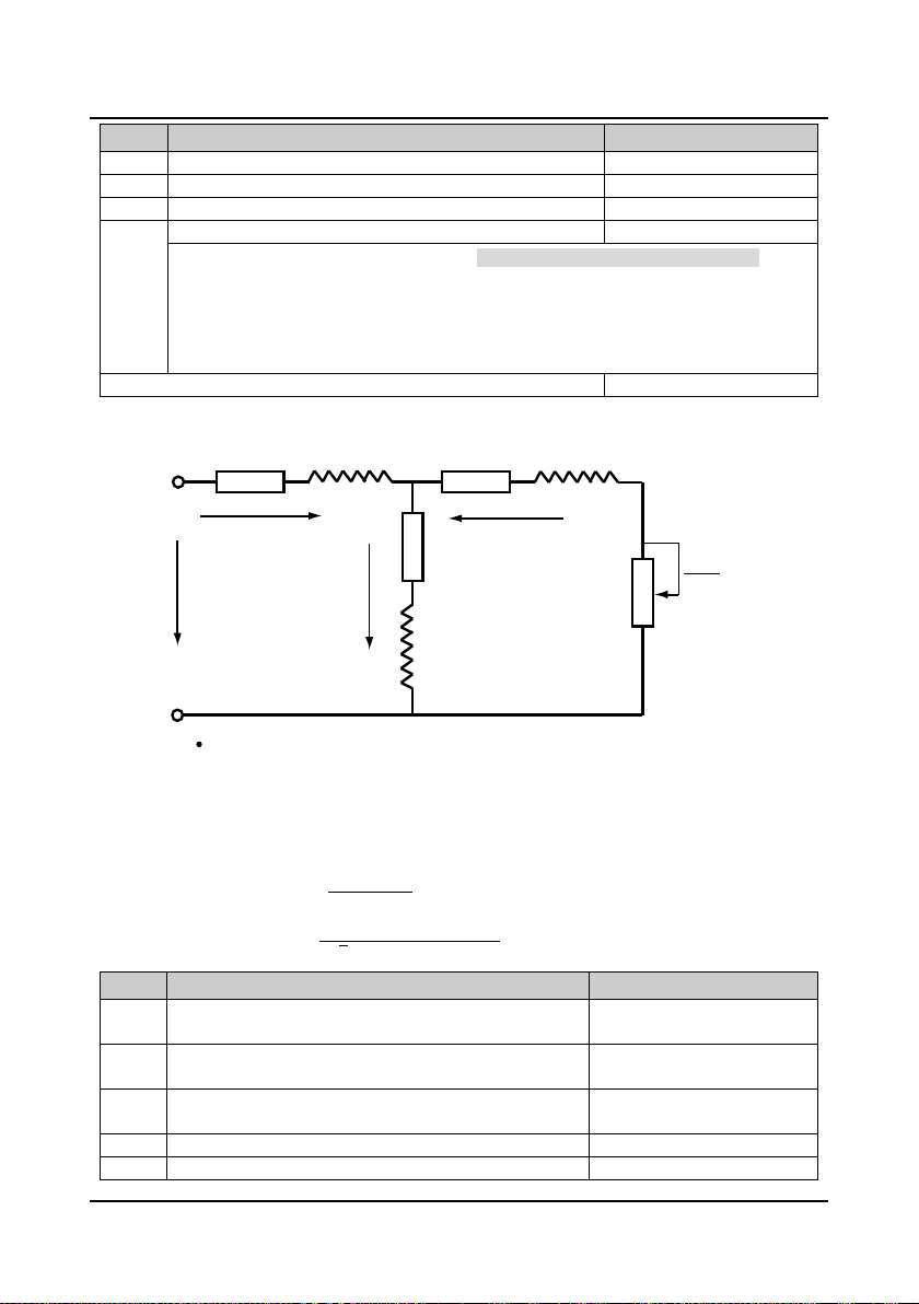
Chapter 6 Functi on Intr oduc ti on Shenzhen Hpmont Technology Co., Ltd
F06.14
No weighing current coefficient
0-9999【3000】
F06.16
No weighing speed-loop KI
1-9999【2000】
F06.17-F06.20 Reserved
【Depend on controller model】
【
【Depend on controller model】
F07.04
Asynchronous motor rated Rpm
1-24000【1440rpm】
I1
I2
Io
R1 R2Ll Ll
L
m
U1
R2
1 - S
S
R1 = F07.07 (Stator resistance) Ll = F07.09 (Leakage inductance)
R2 = F07.08 (Rotor resistance) Lm = F07.10 (Mutual inductance)
Io = F07.11 (Excitation current) S = Slip ratio
Code Name Description Range【factory setting】
F06.13 Reserved
F06.15 No weighing speed-loop KP 1-9999【2000】
F06.14-F06.16 are used to adjust the effect of no weighing auto-compensation (F06.00 = 4).
• The system’s response can be expedited through increasing F06.14-F0616, but system’s
oscillation and overshoot may occur if the value of F06.14-F0616 is too high.
• Generally, it can smoothly start elevator via adjusting F06.14 when debugging.
• Increase F06.14 so as to avoid sliding vehicle at starting moment. Decrease F06.17 so as to
avoid shake at starting moment.
6.2.8 Group F07 Asynchronous Motor Parameters
The relationship among rated torque current, excitation current and motor’s rated curr ent is as
follows:
Rated torque current = F07.05 × F07.02
Excitation current F07.11 = �1 − F07.05
Mutual inductance F07.10 =
Code Name Description Range【factory setting】
F07.00 Asynchronous motor rated power 0.2-400.0kW
F07.01 Asynchronous motor rated voltage 0V-Controller rated voltage
F07.02 Asynchronous motor rated current 0.0-999.9A
F07.03 Asynchronous motor rated frequency 1.00-100.00【50.00Hz】
2
× F07.02
F07.01
2√3
π × F07.03 × F07.11
− F07.09
Depend on controller model】
―68― HD5L Series Controller User Manual
Page 78
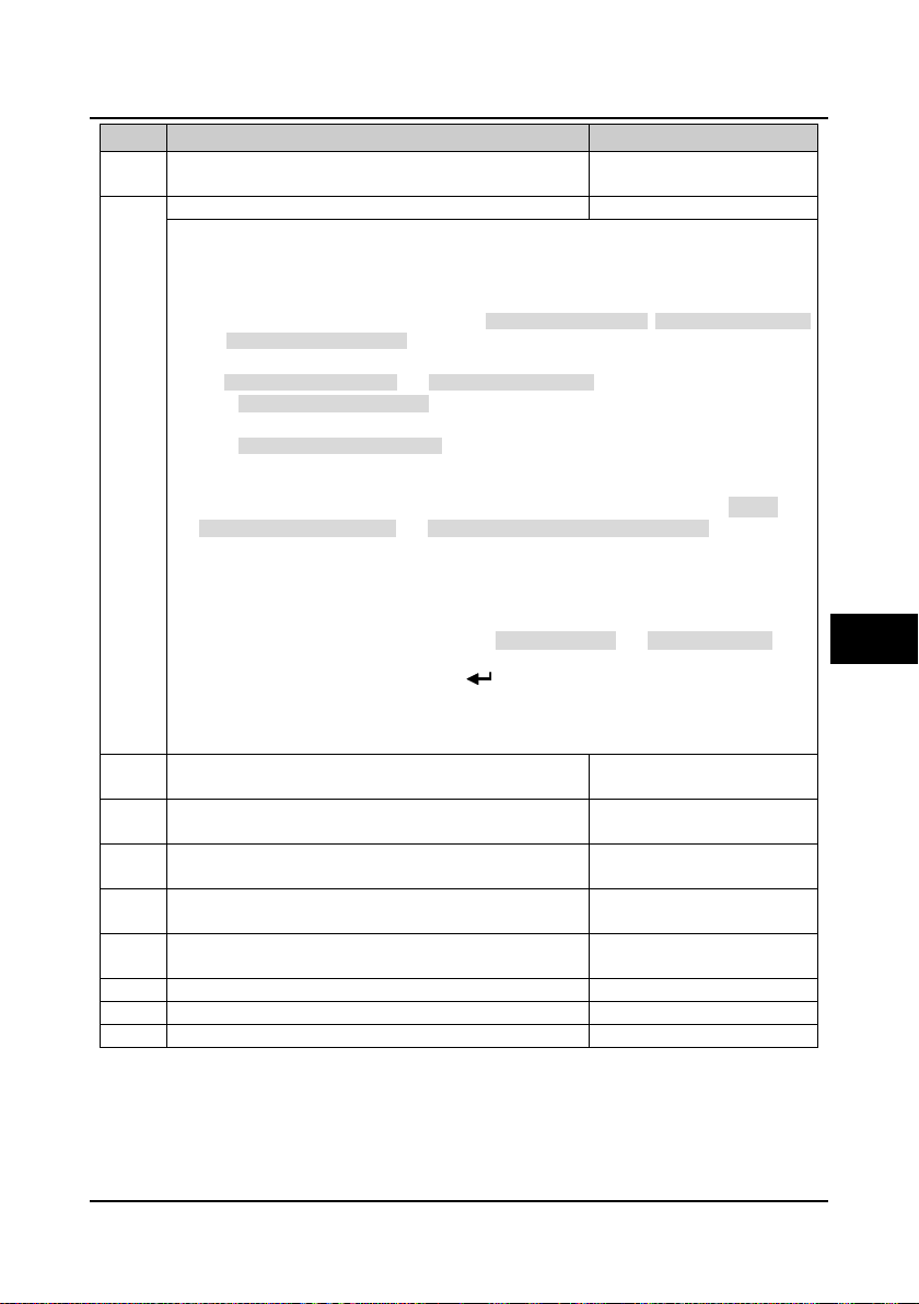
Shenzhen Hpmont Technology Co., Ltd Chapter 6 Function Introduction
【
F07.06
Asynchronous motor parameter auto-tuning
0-2【0】
【Depend on controller model】
【
【Depend on controller model】
【
【Depend on controller model】
F07.13
Asynchronous motor of core saturation coefficient 2
0.00-0.75【0.75】
STOP
RUN
Code Name Description Range【factory setting】
F07.05 Asynchronous motor power factor 0.001-1.000
Depend on controller model】
0: No action.
1: Motor static auto-tuning.
2: Motor rotation auto-tuning.
Motor auto-tuning:
• In the process of motor static auto-tuning, the stator resistance (F07.07), rotor resistance (F07.08)
and leakage inductance (F07.09) will be auto-measured and written into corresponding
parameters automatically.
• For mutual inductance (F07.10) and excitation current (F07.11),
• If at static auto-tuning (F07.06 = 1), it will auto calculate according to F07.05 and F07.02, then
write the result into F07.10 and F07.11;
• If at rotation auto-tuning (F07.06 = 2), the motor will be at rotation state and the auto-measured
value will be written into F07.10 and F07.11.
• When the motor is in rotation state, the oscillation and even the overcurrent might occur. In this
case, please press the key to stop auto-tuning and then properly adjust the F07.21
(oscollation-suppression mode) and F07.22 (oscollation-suppression coefficient) to mitigate the
possible oscillation.
Note: The auto-tuning is enabled only in panel control mode (F00.05 = 0).
Auto-tuning procedures:
1.Input correct motor parameters as per its nameplate (F07.00-F07.04).
2.When F07.06 is set as 2, please set the proper Acc speed(F03.10) and Dec speed (F03.11) and
make sure the motor is disconnected with the load for security.
3.Set F07.06 as 1 or 2 firstly, then press the key, and therewith press key to start
auto-tuning. The LCD will display “Motor para. auto-tuning”.
4.When the auto-tuning is completed, the panel will return to stop display state and the F07.06 will be
reset to 0.
F07.07 Asynchronous motor stator resistance 0.000-9.999Ω
6
F07.08 Asynchronous motor rotor resistance 0.000-9.999Ω
F07.09 Asynchronous motor leakage inductance 0.0-99.9mH
F07.10 Asynchronous motor mutual inductance 0.0-999.9mH
F07.11 Asynchronous motor excitation current 0.0-999.9A
F07.12 Asynchronous motor of core saturation coefficient 1 0.00-0.50【0.50】
F07.14 Asynchronous motor of core saturation coefficient 3 0.00-1.20【1.20】
HD5L Series Controller User Manual ―69―
Depend on controller model】
Depend on controller model】
Page 79

Chapter 6 Functi on Intr oduc ti on Shenzhen Hpmont Technology Co., Ltd
F07.16
Asynchronous motor torque boost end-point
0.1-50.0 (F07.03)【2.0%】
F07.18
Asynchronous motor of slip compensation filter time
0.1-10.0【0.1s】
F07.16max F07.03
Voltage of manual
torque boost
F07.01
Frequency
Voltage
0
Boosted value
F07.16max = 50% F07.03
Load
Slip
Negative slip
100%
-100%
compensation
Positive slip
compensation
Code Name Description Range【factory setting】
F07.15 Asynchronous motor torque boost 0.1-30.0【0.1%】
F07.17 Asynchronous motor of slip compensation gain 0.0-300.0【100.0%】
F07.19 Asynchronous motor of slip compensation limitation 0.0-250.0【200.0%】
The motor’s slip changes with the load torque, which results in the variance of motor speed. Through
• In driving state (the actual speed is lower than the
F07.20 AVR function 0-2【1】
0: No action.
F07.21 Asynchronous motor of oscillation-suppression mode 0,1【0】
0: Oscillation suppression is dependent on the motor’s exciting current component.
F07.22 Asynchronous motor of oscillation-suppression coefficient 0-200【100】
This function is used to damp oscillation when output current is continually unstable.
―70― HD5L Series Controller User Manual
In order to compensate the torque
drop at low frequency, the controller
can boost the voltage so as to boost
the torque.
F07.16 is relative to percentage of
motor rated frequency (F07.03).
slip compensation (the controller will auto adjust its output frequency according to the motor load
torque) to reduce the influence.
setting speed) and in generating state (the actual speed
is higher than the setting speed), the slip compensation
gain (F07.17) should be increased gradually.
• The value of auto slip compensation depends on the
motor’s rated slip, consequently make sure the motor’s
rated frequency (F07.03) and rated Rpm (F07.04) are
set correctly.
Range of slip compensation = Slip compensation limit
(F07.19) × Rated slip.
Rated slip = F07.03 - F07.04 × Np / 60.
• Np is the number of motor pole pairs.
1: Action all the time.
2: No action in deceleration process.
• The output voltage can be regulated to maintain constant via AVR. Thus, normally the AVR
function should be enabled, especially when the input voltage is higher than the rated voltage.
• In deceleration process, if the F07.20 = 0 or F07.20 = 2, the running current will be a little higher;
while if the F07.20 =1, the motor will decelerate steadily and the current will be smaller.
1: Oscillation suppression is dependent on the motor’s torque current component.
This function helps to keep the motor running smoothly through correctly adjusting the setting of
F07.22.
Page 80

Shenzhen Hpmont Technology Co., Ltd Chapter 6 Function Introduction
F08.01
Low speed ASR KI
1-9999【500】
F08.03
High speed ASR KI
1-9999【500】
F08.05
ASR PI swithcing frequency 2
0.00-50.00【15.00Hz】
【
Torque current
setting
Frequency command
+
-
Frequency feedback
PID
Error
Torque limit
F08.04 F08.05
F08.00 /
F08.01
F08.02 /
F08.03
0
Frequency
PI parameter
6.2.9 Group F08 Motor Vector Control Speed-loop Parameters
Code Name Description Range【factory setting】
F08.00 Low speed ASR Kp 1-9999【500】
F08.02 High speed ASR Kp 1-9999【500】
F08.04 ASR PI swithcing frequency 1 0.00-50.00【10.00Hz】
The parameters of F08.00-F08.05 and F08.07 comfirm the PID parameters of ASR. The structure of
As the right figure:
• The system’s response can be expedited through increasing the ASR KP (F08.00, F08.02), but
F08.06 ASR integral limitation 0.0-200.0 (Motor rated
It is used to limit the maximum value of the vector control speed-loop integral.
F08.07 ASR differential time 0.000-1.000【0.000s】
It defines the vector control speed-loop differential time.
F08.08 ASR output filter time 0.000-1.000【0.008s】
It is used to filter the output of ASR regulator.
ASR is shown in figure.
• When the controller operates with frequency in a
range of 0-F08.04, the PI parameters of vector
control are F08.00 and F08.01;
• When the controller operates with frequency
above the value of F08.05, the PI parameters of
vector control are F08.02 and F08.03;
• When the controller operates with frequency in a
range of F08.04-F08.05, P is the linear
interpolation between F08.00 and F08.02, while I
is the linear interpolation between F08.01 and
F08.03.
oscillation may occur if the value of KP is too high.
• The system’s response can be expedited through increasing the ASR KI (F08.01, F08.03), but
oscillation and high overshoot happen easily if the value of KI is too high.
• If F08.01/F08.03 = 0 and the integral function is disabled, the speed-loop works only as a
proportional regulator.
• Generally, the KP should be adjusted firstly to the maximum on condition that the system does not
vibrate, and then the KI should be adjusted to shorten the response time without overshoot.
• It need increase KP and KI, o n condition that shorter dy namic response time i s required during
low frequency operation.
current)
• Generally, it doesn’t need to set F08.07 except for expediting the dynamic response.
• There isn’t speed-loop differential when F08.07 = 0.
• When F08.08 = 0, the speed-loop filter is disabled.
6
180.0%】
HD5L Series Controller User Manual ―71―
Page 81
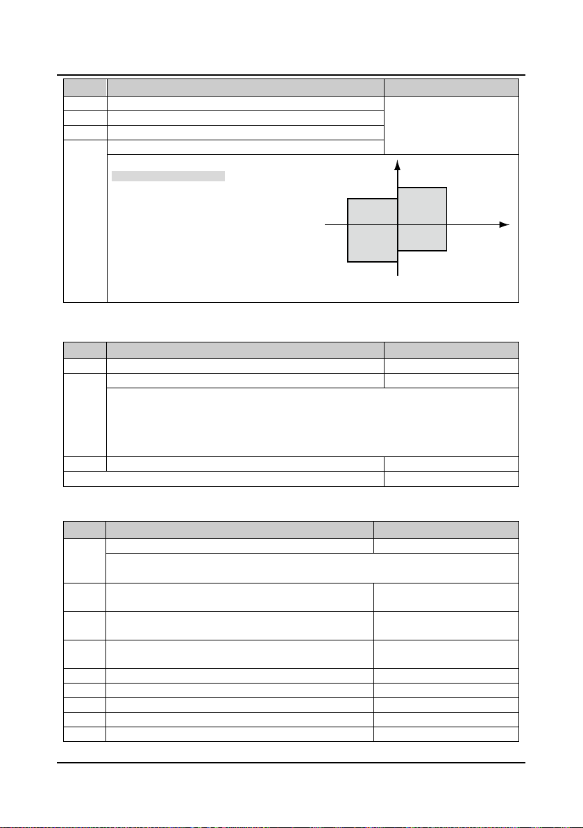
Chapter 6 Functi on Intr oduc ti on Shenzhen Hpmont Technology Co., Ltd
F08.10
DN electrical torque limitation
F08.12
DN regenerative torque limitation
F09.01
Current-loop KI
1-4000【500】
F09.02
Current-loop output filter time
0.000-1.000【0.000s】
F10.00
Synchronous motor type
0,1【0】
【Depend on controller model】
【
【Depend on controller model】
F10.05
Synchronous motor rated rpm
1-24000【96rpm】
F10.07
Synchronous motor quadrature axis inductance
0.0-999.9【0.0mH】
Motor Rpm
Output torque
UpDown
F08.11
F08.09
F08.10
F08.12
Negative
Positive
Code Name Description Range【factory setting】
F08.09 UP electrical torque limitation 0.0-200.0 (F07.02)【180.0%】
F08.11 UP regenerative torque limitation
F08.09-F08.12 are the relative percentage of
motor rated current (F07.02).
As the right figure:
• The bigger torque output, the bigger curren
toutput.
• If the torque is too big, over-current is easy
to occur.
• If the torque is too small, the run speed and
the Acc/Dec speed may deviate from the
setting value.
6.2.10 Group F09 Current-loop Parameters
Code Name Description Range【factory setting】
F09.00 Current-loop KP 1-4000【500】
F09.00 and F09.01 are the PI regulator parameter of current ring (ACR).
• Increasing F09.00 or F09.01 can fasten the system dynamic response to the output torque, while
decreasing F09.00 or F09.01 can build up system stability.
• Too big F09.00 or F09.01 makes the system apt to oscillate, while too small F09.00 or F09.01
affects the system torque output.
F09.03-F09.07 Reserved
6.2.11 Group F10 Synchronous Motor Parameters
Code Name Description Range【factory setting】
0: IPM
1: SPM
F10.01
F10.02
F10.03
F10.04 Synchronous motor rated frequency 1.00-100.00【19.20Hz】
Synchronous motor rated power
Synchronous motor rated voltage
Synchronous motor rated current
0-Controller rated voltage
Depend on controller model】
0.2-400.0kW
0.0-999.9A
F10.06 Synchronous motor stator resistance 0.000-9.999【0.000Ω】
F10.08 Synchronous motor direct axis inductance 0.0-999.9【0.0mH】
―72― HD5L Series Controller User Manual
Page 82

Shenzhen Hpmont Technology Co., Ltd Chapter 6 Function Introduction
【
F10.10
Synchronous motor of angle auto-tuning
0-2【0】
F10.11
Synchronous motor static auto-tuning voltage setting
0.0-100.0 (F10.02)【100.0%】
F10.12
Synchronous motor initial angle
0.0-359.9【0.0°】
F10.14
Synchronous motor SINCOS encoder C amplitude
0-9999【2048】
F10.16
Synchronous motor SINCOS encoder D amplitude
0-9999【2048】
F10.18-F10.20 Reserved
F11.02
PG direction setting
0,1【0】
F11.04
The protocol of serial communication PG
0-9【0】
F11.05
Detecting time of PG wire disconnection
0.00-2.00s【1.00】
Code Name Description Range【factory setting】
F10.09
0: No action.
Synchronous motor Back EMF
1: Static auto-tuning.
2: Rotation auto-tuning.
• Refer to section 7.1.3 about parameter auto-tuning.
0-Controller rated voltage
380V】
F10.13 Synchronous motor of Z pulse initial angle 0.0-359.9【0.0°】
F10.15 Synchronous motor SINCOS encoder C zero-bias 0-9999【2048】
F10.17 Synchronous motor SINCOS encoder D zero-bias 0-9999【2048】
If synchronous motor alarms over-current at static auto-tuning, the setting value should be smaller.
6.2.12 Group F11 PG Parameters
In elevator appli c ation, the PG is necessary for the motor. Please refer to section 4.6 for PG .
Code Name Description Range【factory setting】
F11.00 HD5L PG card 1-4【4】
1: HD-PG2-OC-FD is valid. Only for asynchronous motor.
F11.01 PG P/R 1-9999【2048】
It defines the connection sequence of PG whether the same as that of the drive-motor connection.
F11.03 PG signal filter coefficient 0x00-0x77【0x11】
Units: Low-speed filter coefficient.
2: HD-PG6-UVW-FD is valid. Only for synchronous motor.
3: HD-PG5-SINCOS-FD is valid. Only for synchronous motor.
4: HD-PG9-SC-FD is valid. Only for synchronous motor. (support Endat)
• In order to change the connection of AB two phases of the PG, you can change this parameter.
0: The same direction.
1: The reverse direction.
Tens: High-speed filter coefficient.
6
0: Endat.
F11.05 specifies the duration time for detecting PG wire disconnection fault.
1-9: Reserved.
The controller detects the PG wire disconnection and the duration time exceed F11.05, then the
controller alarms E0031 fault (PG disconnection).
• No detection will be conducted when F11.05 is set as 0.
HD5L Series Controller User Manual ―73―
Page 83

Chapter 6 Functi on Intr oduc ti on Shenzhen Hpmont Technology Co., Ltd
F12.02
DI2 terminal function
000-134【2】
F12.04
DI4 terminal function
000-134【4】
F12.06
DI6 terminal function
000-134【6】
F12.08
DI8 terminal (I/O card terminal) function
000-134【0】
F12.10
DI10 terminal (I/O card terminal) function
000-134【0】
F12.12
DI12 terminal (I/O card terminal) function
000-134【0】
123
6.2.13 Group F12 Digital I/O Terminal Parameters
Code Name Description Range【factory setting】
F12.00 Input terminal filter time 0.000-1.000【0.010s】
This function code is to define filter time of digital input termianl and to set input terminal sensibility.
• The input terminals are susceptible to interference which will result in misoperation so that you
could increase this parameter setting value. However, too long filter time will affect adjustment
sensibility.
F12.01 DI1 terminal function 000-134【1】
F12.03 DI3 terminal function 000-134【3】
F12.05 DI5 terminal function 000-134【5】
F12.07 DI7 terminal (I/O card terminal) function 000-134【0】
F12.09 DI9 terminal (I/O card terminal) function 000-134【0】
F12.11 DI11 terminal (I/O card terminal) function 000-134【0】
0: Disable. It disables the terminal’s function. The controller ignores the signal input via this terminal.
2,3: UP/DN.
Note: When hundreds is set as 0, it means normally open input; while set as 1 it means
normally closed input.
• The unwanted terminal is recommended to be set as 0 so as to avoid wrong connection or
action.
1: Controller enabled. (EN)
• When enabled, the controller is enabled to run;
• When disabled, the controller is disabled to run and will be in auto stop state.
• When no terminal selects this function, it defaults that the controller is at enabled state.
• You can set control terminal to control the controller’s up and down.
UP Terminal DN Terminal Selection
0 0 Stop
0 1 Down
1 0 Up
1 1 Stop
―74― HD5L Series Controller User Manual
Page 84
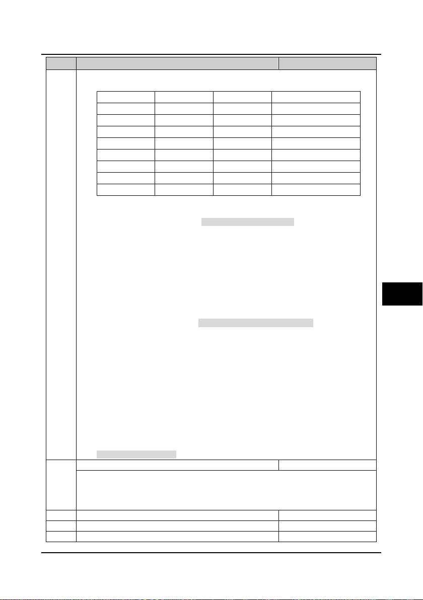
Shenzhen Hpmont Technology Co., Ltd Chapter 6 Function Introduction
F12.13
MS in combination of filter time
0.000-2.000【0.010s】
F12.14
Reserved
F12.16
DO2 terminal function
0-19【3】
STOP
Code Name Description Range【factory setting】
4-6: MS1-MS3.
7: Inspection input (INS).
8: Battery-driven input (BAT).
9: Contactor feedback input (CSM).
• The switch weight signals can be input through this terminal. Based on these signals, the
15: Motor over-heating input (OH).
17: Up forced Dec input (UPF).
34: External fault (EXT).
• You can achieve 8-step speed running curve via terminals logic combination, as follow table.
MS3 Terminal MS2 Terminal MS1 Terminal Multi-speed setting
0 0 0 Multi-speed 0 (F05.00)
0 0 1 Multi-speed 1 (F05.01)
0 1 0 Multi-speed 2 (F05.02)
0 1 1 Multi-speed 3 (F05.03)
1 0 0 Multi-speed 4 (F05.04)
1 0 1 Multi-speed 5 (F05.05)
1 1 0 Multi-speed 6 (F05.06)
1 1 1 Multi-speed 7 (F05.07)
• If enabled, elevator will do inspection running.
• This signal, when used together with UP/DN (No. 2 or No. 3 function) command, can control the
elevator to go up or down during inspection.
• If enabled, elevator will enter battery-driven running state.
10: Brake feedback input (BSM).
11-14: Weighing signal input 1-4 (WD1-WD4).
controller sets the torque bias and starts the elevator stably.
• Select among WD1-WD4 according to the actual number of weighing devices and set the load
of switches based on the setting of F6.08-F6.11 (DI weighing signal 1-4).
• If many terminals are enabled, the max No. terminal will be enabled.
• For example: When WD1 and WD2 are enabled simultaneously, only WD2 is the valid one.
16: Fault reset input (RST).
• Upon controller fault alarms, you can reset the fault by this terminal.
• The function of RST terminal is the same as the key on the panel.
18: Down forced Dec input (DNF).
19-33: Reserved.
• The fault signal of external equipment can be input through this terminal, so that controller can
monitor that equipment and respond accordingly. When the controller receives the EXT signal,
E0024 fault (external faulty) will be displayed.
6
This parameter defines the MS in combination of filter time to make up for the time error of MS input
terminals.
• Change this parameter value according to the change asynchronous level of numbers of MS input
F12.15 DO1 terminal function 0-19【2】
HD5L Series Controller User Manual ―75―
terminals.
Page 85

Chapter 6 Functi on Intr oduc ti on Shenzhen Hpmont Technology Co., Ltd
F12.18
RLY2 relay (I/O card relay) function
0-19【0】
F12.20
RLY4 relay (I/O card relay) function
0-19【0】
F12.21
Output terminal logic setting
00-0x3F【0】
Code Name Description Range【factory setting】
F12.17 RLY1 relay function 0-19【14】
F12.19 RLY3 relay (I/O card relay) function 0-19【0】
0: Disable. The output terminals will be at no function state and no any action.
3: Controller is at zero-speed running.
1: Controller is ready.
• Signal ON will be output if controller has no error.
2: Controller is running.
• Indication signal will be output if controller is at running state.
• ON signal will be output if controller output speed is zero but at running state.
4: Zero-speed.
• ON signal will be output if controller output speed is zero.
5: Contactor output control.
• This function is used to open/close the output contactor.
6: Brake output control.
• This function is used to open/close the brake.
7,8: FDT1, FDT2.
• Refer to parameters F05.12-F05.13.
9: Speed arrived signal (FAR).
• The indication signal will be output when the controller’s output frequency is within the FAR
range. The detect range is set by F05.16 (FAR range).
• The indication signal will be output too after the controller stops.
10: Up signal output.
• When the elevator is at up running, the controller will output ON signal.
11: Down signal output.
• When the elevator is at down running, the controller will output ON signal.
12: Under-voltage.
• ON signal will be output when the controller is during under-voltage state.
13: Reserved.
14: Controller fault.
• ON signal will be output when the controller is faulty.
15: Elevator stop.
• When the elevator stops, the controller will stop and output an 2s pulse. The controller will
disable the running command according to this signal.
16-19: Reserved.
It defines that each bit (binary) of this function represents different physical sources.
• Positive logic: When multi-function input terminals are connected to corresponding common port,
this logic is enabled. Otherwise the logic is disabled.
• Negative logic: When multi-function input terminals are connected to corresponding common port,
this logic is disabled. Otherwise the logic is enabled.
RLY4 RLY3 RLY2 RLY1 DO2 DO1
• 0 represents positive logic, while 1 represents negative logic.
F12.22-F2.24 Reserved
―76― HD5L Series Controller User Manual
Bit5 Bit4 Bit3 Bit2 Bit1 Bit0
Page 86

Shenzhen Hpmont Technology Co., Ltd Chapter 6 Function Introduction
F13.01
AI2 function
0-2【0】
F13.03
AI4 function
0-3【0】
F13.04
AI1 bias
F13.10
AI3 bias
F13.05
AI1 gain
F13.11
AI3 gain
F13.06
AI1 filter time
F13.12
AI3 filter time
F13.17
AO2 terminal output function
0-9【0】
I/O card
+5V
10k
AI4+
AI4-
CN3
1
3
CN2
1
3
VIV
R
Thermistor
Analogue
actual value
Analogue
input filtering
Analogue input gain
Analogue input bias
Analogue value
after computing
6.2.14 Group F13 Analogue I/O Terminal Parameters
Code Name Description Range【factory setting】
F13.00 AI1 function 0-2【0】
F13.02 AI3 function 0-2【0】
0: Disable.
1: Speed setting.
2: Weighing signal.
3: Motor over-heating signal input (only AI4 enabled).
• Connect the electronic thermistor embedded
motor stator coils to the controller’s analogue
input, as the right figure.
• Refer to parameters F17.01 and F17.02 about
the thermistor.
• AI1 input range: 0-10V.
• AI2-AI4 input range: -10-+10V.
-100.0-100.0【0.0%】
F13.07 AI2 bias
F13.13 AI4 bias
-10.00-10.00【1.00】
F13.08 AI2 gain
F13.14 AI4 gain
0.01-10.00【0.05s】
F13.09 AI2 filter time
F13.15 AI4 filter time
When select AI1-AI4 as open-loop frequency setting source, the relationship between the analogue
input and the analogue value after compulting is shown as figure:
• The formula of analogue input gain and bias and analogue value is: Y=kX+b
• Here: Y is the analogue value after computing, X is the value before adjusting, k is the
analogue input gain (F13.05, F13.08, F13.11, F13.14), b is the analogue input bias (F13.04,
F13.07, F13.10, F13.13).
• F13.06, F13.09, F13.12 and F13.15 define the source filter time. It is used to filter the analogue
signal.The bigger the constant, the higher the immunity level, but the response time is prolonged
with the increase of this constant. That is, the smaller the constant, the shorter the response time,
but the lower the immunity level.
F13.16 AO1 terminal output function 0-9【0】
6
0: Disable.
1: Running speed (0-max output speed).
2: Setting speed (0-max output speed).
HD5L Series Controller User Manual ―77―
Page 87

Chapter 6 Functi on Intr oduc ti on Shenzhen Hpmont Technology Co., Ltd
.
.
-
-
F13.18
AO1 bias
-100.0-100.0【0.0%】
0
10
F13.18=0
F13.18=50%
50%
100%
Value after regulating (V)
Value before regulating (V)
0
10
100%
F13.19=100%
F13.19=200%
5
Value after regulating (V)
Value before regulating (V)
Code Name Description Range【factory setting】
Note:
At up, up limit of No. 1 and No. 2 function is corresponding to 10V, while down limit is
1
corresponding to 5V;
2
At down, up limit of No. 1 and No. 2 function is corresponding to 0V, while down limit is
corresponding to 5V.
3: Output current (0-twice of controller rated current).
4: Output voltage (0-1.2 times of controller rated voltage).
5: DC bus voltage (0-2.2 times of controller rated voltage).
Note: Up limit of No. 3
6: AI1 input (0-10V).
7: AI2 input (-10-10V/0-20mA).
8: AI3 input (-10-10V/0-20mA).
9: AI4 input (-10-10V/0-20mA).
Note: When the negative voltage of No. 7
absolute value.
F13.19 AO1 gain 0.0-200.0【100.0%】
• This parameter is used to realise the proportional relation adjustment of AO1 analogue output.
• The formula is: Y=kX+b
• Y is actual output value, X is output value before being adjusted, k is analogue output gain
(F13.19), b is analogue output bias (F13.18).
The relationship between analogue output and bias is shown as following figure.
5 functions is corresponding to max output voltage 10V.
9 function is as input, the AO will output its
The relationship between analogue output and gain is shown as following figure.
F13.20 AO2 bias -100.0-100.0【0.0%】
F13.21 AO2 gain 0.0-200.0【100.0%】
Refer to parameters F13.18 and F13.19.
―78― HD5L Series Controller User Manual
Page 88

Shenzhen Hpmont Technology Co., Ltd Chapter 6 Function Introduction
F14.04
Detection time of communication timeout
0.0-1000.0【0.0s】
F14.05
Detection time ofcommunication error
0.0-1000.0【0.0s】
F14.06-F14.47 Reserved
F15.03
Run display parameter 2 set
0-32【6】
F15.05
Run display parameter 4 set
0-32【11】
F15.07
Run display parameter 6 set
0-32【0】
6.2.15 Group F14 SCI Communication Parameters
Refer to Appendix B (Page 129) for the communication function.
Code Name Description Range【factory setting】
F14.00 Data format 0-5【0】
0: 1-8-2 format, no parity, RTU.
1: 1-8-1 format, even parity, RTU.
2: 1-8-1 format, odd parity, RTU.
3: 1-7-2 format, no parity, ASCII.
4: 1-7-1 format, even parity, ASCII.
5: 1-7-1 format, odd parity, ASCII.
F14.01 Baud rate selection 0-5【3】
0: 1200bps.
1: 2400bps.
2: 4800bps.
3: 9600bps.
4: 19200bps.
5: 38400bps.
F14.02 Local address 0-247【2】
When F14.02 = 0, it means broadcast address.
F14.03 Host PC response time 0-1000【0ms】
When the time at no communication data exceeds the setting time of F14.04, it will be considered as
E0028 fault (SCI timeout faulty).
• When F14.04 = 0, it will not detect communication time out.
When the time at communication error exceeds the setting time of F14.05, it will be considered as
E0029 fault (SCI faulty).
• When F14.05 = 0, it will not detect the communication error.
6.2.16 Group F15 Display Control Parameters
Code Name Description Range【factory setting】
F15.00 Language selection 0,1【0】
It defines the displaying language on the LCD panel.
0: Chinese.
1: English.
2-9: Reserved.
F15.01 LCD panel display contrast 1-10【5】
To select LCD display contrast.
F15.02 Run display parameter 1 set 0-32【5】
F15.04 Run display parameter 3 set 0-32【10】
F15.06 Run display parameter 5 set 0-32【0】
HD5L Series Controller User Manual ―79―
6
Page 89

Chapter 6 Functi on Intr oduc ti on Shenzhen Hpmont Technology Co., Ltd
F15.09
Stop display parameter 2 set
0-32【14】
F15.11
Stop display parameter 4 set
0-32【26】
F15.13
Stop display parameter 6 set
0-32【0】
Code Name Description Range【factory setting】
F15.08 Stop display parameter 1 set 0-32【4】
F15.10 Stop display parameter 3 set 0-32【16】
F15.12 Stop display parameter 5 set 0-32【27】
The panel displays parameters which difine the run state (F15.02-F15.07) and stop state (F15.08-
F15.13).
• It can be cycling displayed by key on the panel.
• Each display parameter of content can be set corresponding to 32 states.
• For instance: when set F15.08 as 7, the stop display parameter is setting Rpm at initial power on.
0: Disable.
1: Controller rated current.
2: Controller state.
3: Operate channel.
4: Setting speed.
5: Setting speed. (after Acc/Dec)
6: Output frequency.
7: Setting Rpm.
8: Actual Rpm.
9: Reserved.
10: Output voltage.
11: Output current.
12: Output torque.
13: Output power.
14: DC bus voltage.
15: AI1 voltage.
16: AI1 voltage (after disposal).
17: AI2 voltage.
18: AI2 voltage (after disposal).
19: AI3 voltage.
20: AI3 voltage (after disposal).
21: AI4 voltage.
22: AI4 voltage (after disposal).
23: AO1 output.
24: AO2 output.
25: Heatsink temperature.
26: Input terminal state.
27: Output terminal state.
28: MODBUS state.
29: Total time at power on (hour).
30: Total running time (hour).
31, 32: Reserved.
―80― HD5L Series Controller User Manual
Page 90

Shenzhen Hpmont Technology Co., Ltd Chapter 6 Function Introduction
【Depend on controller model】
F16.06
Contator fault detect time
0.0-10.0【2.0s】
6.2.17 Group F16 Enhance Function Parameters
Code Name Description Range【factory setting】
F16.00 Zero-speed running signal delay time 0.00-10.00【0.30s】
It defines the delay time from the controller at zero-speed run state to zero-speed run signal output.
F16.01 Zero-speed signal delay time 0.00-10.00【0.30s】
It defines the delay time from the controller at zero-speed state to zero-speed signal output.
F16.02 Current keep time after stop co mmand 0-9999【0ms】
To eliminate the motor current noise at stop, when the brake is over, the cut-off run signal will reduce
the current to zero after the time defined by F16.02.
F16.03 Fan control mode 0-2【0】
It defines the fan control mode. If there is over-heat protection, the fan will run all the time.
0: Auto stop.
• The fan runs all the time when the controller is in running state. After the controller stops for the
time set by F16.04, the fan will auto stop if there isn’t over-heat protection.
1: Immediately stop.
• The fan runs all the time when the controller is in running state, but stops when the controller stops.
2: Run when power on.
• The fan runs continuously after the controller is switched on.
F16.04 Fan keep time 0.0-600.0【30.0s】
F16.05 Brake unit action voltage 380-750V
For 380V voltage class controller, the braking voltage range is 630-750V.
For 220V voltage class controller, the braking voltage range is 380-450V.
Note: The braking action enable only in the controller run state.
F16.07 Multi-speed inspection select 0-7【0】
When the digital input terminals are not enough, the combinations of MS1-MS3 can achieve the
inspection run.
• When there is digital input terminal set as inspection terminal INS (No. 7 function), only need set
F16.07 as 0 to enter terminal inspection run.
• When there isn’t digital input terminal set as inspection terminal INS (No. 7 function), the inspection
run can be achieved via the combination of MS1-MS3.
• When the value of MS1-MS3 is equal to the value of F16.07, enter MS inspection run at MS
run speed (F05.00-F05.07).
Note: When the MS run speed (F05.00-F05.07) exceeds 0.630m/s, run at 0.630m/s.
F16.08 Zero-speed threshold 0.001-0.010【0.003m/s】
When the present run speed does not exceed F16.08, the system run speed will be condidered as 0.
After zero-speed delay signal, the zero-speed signal will be output.
F16.09 Selection at motor overheat fault 0,1【0】
0: When detect that the motor is overheated, report E0020 (motor overheated) after motor stop.
1: When detect that the motor is overheated, report E0020 (motor overheated) at once.
F16.10 The coefficient of frequenc y demultiplication of
HD-PG9-SC-FD
To set the coefficient of frequency demultiplication of HD-PG9-SC-FD.
F16.11-F16.24 Reserved
1-256【1】
HD5L Series Controller User Manual ―81―
6
Page 91

Chapter 6 Functi on Intr oduc ti on Shenzhen Hpmont Technology Co., Ltd
F17.00
Input voltage at motor overheated
0.00-10.00【0.00V】
F17.03
The detect base of lack of input
0-100【30%】
F17.06
The detect time of lack of output
0.0-20.0【3.0s】
123
F17.07
Motor overload protect factor
20.0-110.0【100.0%】
Motor overload protect factor (F17.07)=
Motor rated current (F07.02 or F10.03
)
Controller rated output current
× 100%
6.2.18 Group F17 Fault Protect Parameters
Motor overheated fault (F17.0 0-F17.02)
It can connect the electronic thermistor embedde d motor stator coils to the controller’s analogue
input AI4 in order to protect mo tor ov erheating. The connection is shown as 4.5.3 of I/O Card
Terminal Connection.
Code Name Description Range【factory setting】
F17.01 Thermistor type 0-2【0】
0: Does not detect the motor overheating (NC).
1: Positive charateristic (PTC).
• When AI4 input is exceeded F17.00, the controller will alarm E0020 fault (motr overheated).
2: Negative charateristic (NTC).
• When AI4 input is less than F17.00, the controller will alarm E0020 fault (motr overheated).
Note: Only when correctly set CN2 and CN3 of I/O card will do the motor overheated detection.
F17.02 Threshold resistance at motor overheated 0-10.0【5.0kΩ】
Input and output phase loss fault (F17.0 3-F17.06)
Code Name Description Range【factory setting】
F17.04 The detect time of lack of input 0.0-5.0【1.0s】
F17.03 value is a percentage of the controller’s rated voltage.
F17.05 The detect base of lack of output 0-100【20%】
When the controller detects certain input voltage not hit the preset detect base (F17.03) and exceed
the preset detect time (F17.04), the controller will alarm E0015 fault (lack of input).
• When F17.03 or F17.04 is set as 0 or in the battery driven run mode, the controller will not detect
input phase loss fault.
F17.05 value is a percentage of the controller’s rated current.
When the controller detects certain output current not hit the preset detect base (F17.05) and exceed
the preset detect time (F17.06), the controller will alarm E0016 fault (lack of output).
• When F17.05 or F17.06 is set as 0, the controller will not detect output phase loss fault.
Motor fault (F17.07)
Code Name Description Range【factory setting】
The motor overload protection factor can be set as 100% when the controller drives a motor of the
same power class.
To protect the motor when the motor power is smaller than the standard matched power, you need to
set a proper motor overload protection factor (F17.07). The factor can derive from the following
formula:
―82― HD5L Series Controller User Manual
Page 92

Shenzhen Hpmont Technology Co., Ltd Chapter 6 Function Introduction
F17.08
Fault auto reset times
0-100【0】
Fault auto-reset function a nd fault relay action (F17.08-F17.10)
Auto reset function enables the controller to reset the fault as per the preset times (F17.08) and
interval (F17.09).
The following faults do not have the auto reset function:
E0008: Power module faulty E0021: Control board EEPROM faulty
E0010: Brake unit f aulty E0023: Parameter setting faulty
E0013: Soft start failed E0024: External faulty
E0014: Current detect fa ulty E0036: Contactor fau lty
Code Name Description Range【factory setting】
F17.09 Fault auto reset interval 2.0-20.0【5.0s/times】
When F17.08 = 0, it means “auto reset” is disabled and the protective device will be activated in case
F17.10 Fault relay action select 00-11【00】
Units: During auto reset
of fault.
• If no other fault is detected within 5 minutes, the auto reset count will be automatically cleared.
• On condition of external fault reset, auto reset count will be cleared.
• 0: Fault relay doesn’t act.
• 1: Fault relay acts.
Tens: During DC bus low
• 0: Fault relay doesn’t act.
• 1: Fault relay acts.
Note: It need preset the relay function as No. 14 function. (Controller fault)
6
HD5L Series Controller User Manual ―83―
Page 93

Chapter 6 Functi on Intr oduc ti on Shenzhen Hpmont Technology Co., Ltd
【
F17.13
Output freqency at NO.5 fault
F17.14
DC bus vlotage at NO.5 fault
F17.17
Input terminal state at NO.5 fault
F17.18
Output terminal state at NO.5 fault
F17.21
NO.4 fault interval
F17.22
NO.3 fault type
F17.25
NO.2 fault interval
F17.26
NO.1 fault type
Fault history (F17.11-F17.27)
F17.12-F17.19 record the controller state parameters at the last fault.
F17.20-F27 record th e t y pe and interval per time of four f aults before the lat est. The interval’s
unit is 0.1 hour.
Code Name Description Range【factory setting】
F17.11 NO.5 fault type
F17.12 Setting freqency at NO.5 fault
F17.15 Output voltage at NO.5 fault
F17.16 Output current at NO.5 fault
F17.19 NO.5 fault interval
F17.20 NO.4 fault type
F17.23 NO.3 fault interval
F17.24 NO.2 fault type
F17.27 NO.1 fault interval
actual value】
―84― HD5L Series Controller User Manual
Page 94
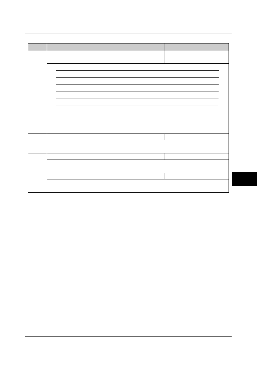
Shenzhen Hpmont Technology Co., Ltd Chapter 6 Function Introduction
【
6.2.19 Group F18 PWM Parameters
Code Name Description Range【factory setting】
F18.00 Carrier frequency 1-16kHz
depend on controller model】
F23.00 defines the carrier frequency of PWM output wave.
Controller power Setting range Factory setting
0.2-22kW 1-16kHz 8kHz
30-45kW 1-12kHz 6kHz
55-90kW 1-6kHz 4kHz
110kW and above 1-4kHz 2kHz
1234
• The carrier frequency will affect the operating noise of the motor. The higher the carrier frequency,
the lower the noise made by the motor. Please properly set the carrier frequency.
• When the value is higher than the factory setting, the controller should be derated by 5% when
per 1kHz is increased compared to the factory setting.
F18.01 Carrier freqency auto adjust enable 0,1【0】
0: Disable.
1: Enable.
F18.02 PWM overmodulation enable 0,1【1】
0: Disable.
1: Enable.
F18.03 PWM overmodulation mode 0,1【0】
0: Two phase / Three phase swtich.
1: Three phase.
6.2.20 Group F19 Reserved
6.2.21 Group F20 Reserved
6.3 Group Y Manufacturer Function Parameters
6
The Group y is the manufacturer parameters group for debugging at the factory before delivery.
HD5L Series Controller User Manual ―85―
Page 95

Page 96

Shenzhen Hpmont Technology Co., Ltd Chapter 7 Elevator Application Guidance
HD5L
MCCB
U
V
W
L1
L2
L3
R
S
T
Three-phaseinputpowersupply
Speedfeedback
Contactor
Weighingsignalfeedback
Car
Counter weight
380V 50/60Hz
Elevator
controller
Input
terminal
Output
terminal
M
PG
Chapter 7 Elevator Application Guidance
This chapter will guide you through the basic procedures of system design and function code
configuration when the controller is applie d in elevator control system.
7.1 Basic Debug Procedures
7.1.1 System Analysis and Wire
We recommend you to analyze the actual application requirements before the wiring design.
Basic configuration for elevator system with HD5L is shown in Figure 7-1:
7.1.2 Set Basic Parameters
1. Correctly set F00.00 (motor type) and F00.01 (control mode) according to motor type.
2. Set relevant parameters of motor. For the asynchronous motor, set Group F07. For the
synchronous motor, set Group F10.
3. Set F00.02 (elevator rated speed) and F00.04 (traction machine mechanical parameters)
according to the elevator requirement and motor parameters .
4. Set encoder relevant parameters of Group F11 according t o t he encoder c onfigured to motor.
5. Set digital I/O function parameters of Group F12 according to the actual wiring.
6. Set the parameter according to the actual running mode:
• Terminal MS running mode: Set MS relevant parameters of Group F05 according to the
elevator actual requirement and the controller. Set Acc/Dec curve parameters of Group F03
according to the elevator speed.
• Terminal analogue running mode: Set analogue curve parameters of Group F04 and
analogue I/O terminal parameters of Group F13 according to the elevator actual requirement
and the controller. The bigger Acc/Dec curve parameters of Group F03 are set, the quicker
HD5L catch the speed command of elevator controller.
HD5L Series Controller User Manual ―87―
Figure 7-1 Basic configuration for elevator system with HD5L
7
Page 97

Chapter 7 Elevator Application Guidance She nzhen Hpmont Technology Co., Ltd
RUN
RUN
RUN
7.1.3 Motor Parameter Auto-tuning
Note: The crane car is ne eded for the rotatio n auto-tuning but not for the st a tic auto-tuning.
Asynchronous motor parameter auto-tuning
1. You should set F00.05 as 0 (panel control).
2. Set F07.06 as 1 (static auto-tuning) or 2 (rotation auto-tuning), then press key of panel
to do parameter auto-tuning. T he motor does not rotate at static auto-tuning but rotate at rotation
auto-tuning.
Note: When auto-tuning, it need open the run contactor; if at rotation auto-tuning, it need open
the brake contactor manually too.
Synchronous motor rotation auto-tuni ng wi t h A/B/Z/U/V/W encoder
1. You should set F00.05 as 0 (panel control).
2. Set F10.10 as 2 (rotation angle auto -tuning), then press key of panel to do parameter
auto-tuning.
3. Auto-tuning process: The controller with DC fixes the motor to one direction, then slowly starts
the motor for a while and finally stops. When finishes auto-tuning, F10.12 (motor initial angle) will
be obtained.
Note:
1. During step 2 and step 3, manually open the brake contactor and the run contactor together.
2. If the system has synchronous mo tor radial contactor, the short-circuit signal of radial contactor
should be removed. Otherwise it will c ause over-current fau lt.
Synchronous motor static auto-tuni ng wi t h A/B/Z/U/V/W encoder
1. You should set F00.05 as 0 (panel control).
2. Set F10.10 as 1 (static angle auto-tuning), then press key of panel to do parameter
auto-tuning.
3. During auto-tuning, the controller will make a serial pulse voltage and the motor will buzz.
When buzz is over and the panel returns to stop state, please check and record D04.05.
4. Restart step 2 and step 3, check a nd recor d D04 .05. Then compare the twice obtained value of
D04.05.
If the comparison value is smaller than 5000, it means that the steps are su cces s. Otherwise you
should check the encoder connection and then restart step 2-4.
Note of step 4:
If the comparison value is too large, you could count it according to the follow ing for mula. And if
the result is smaller than 5000, it means that the above steps are success too.
Formula: 65535 + smaller value – larger value < 5000
―88― HD5L Series Controller User Manual
Page 98

Shenzhen Hpmont Technology Co., Ltd Chapter 7 Elevator Application Guidance
RUN
5. Set F00.05 according to elevator control mode, and set F06.00 as 0 (no pre-torque
compensation).
6. Set inspection run command and direction so that the motor slowly runs, F10.12 (motor initial
angle) will be obtained the auto-tuning process is finished.
We should also pay attention to the followi ng cir c umst a nc e s at ste p 6 of low speed
operation:
1. The setting direction and the actually running direction are not the same.
Take measures: Set the reverse value of F00.08 (run direct ion), then restart auto-tuning.
2. There is fault such as over-current or encoder reversion enabled etc. It may be encoder
revers ion enable d.
Take measures: Set F11.02 as 1 (the reverse d irection of PG card), then resta rt auto-tuning.
.123
Note:
1. During step 2 and step 3, it need manually open the run contactor.
2. If the system has synchronous mo tor radial contactor, the short-circuit signal of radial contactor
should be removed. Otherwise it will c ause over-c urrent fau lt.
3. If the system is pow e r of f before fi n i sh the step 6, you should restart auto-tuning.
Synchronous motor rotation auto-tuni ng wi t h SINCOS encoder
1. You should set F00.05 as 0 (panel control).
2. Set F10.10 as 2 (rotation angle auto -tuning), then press key of panel to do parameter
auto-tuning.
3. Auto-tuning process: The controller with DC fixes the motor to one direction, then slowly starts
the motor for one cycle and finally stops. When finishes auto-tuning, F10.14-F10.17 (encoder
relevant parameters) and F10.12 (motor initial angle) will be obtained.
Note: During step 2 and step 3, manually open the brake contactor and the run contactor
together.
7
HD5L Series Controller User Manual ―89―
Page 99

Chapter 7 Elevator Application Guidance She nzhen Hpmont Technology Co., Ltd
RUN
Synchronous motor static auto-tuni ng wi t h SINCOS encoder
1. You should set F00.05 as 0 (panel control).
2. Set F10.10 as 1 (static angle auto-tuning), then press key of panel to do parameter
auto-tuning.
3. During auto-tuning, the controller will make a serial pulse voltage and the motor will buzz.
When buzz is over and the panel returns to stop state, please check and record D04.05.
4. Restart step 2 and step 3, check and record D04.05. The n co mpare the tw ice obtained value of
D04.05.
If the comparison value is smaller than 5000, it means that the steps are su cces s. Otherwise you
should check the encoder connection and then restart step 2-4.
Note of step 4:
If the comparison value is too large, you could count it according to the follow ing for mula. And if
the result is smaller than 5000, it means that the above steps are success too.
Formula: 65535 + smaller value – larger value < 5000
5. Set F00. 05 according to elevator control mode, and set F06.00 as 0 (no pre-torque
compensation).
6. Set inspection run command and direction so that the motor slowly runs for a circle then keeps
at zero-speed. When revoke run command and direction at the moment, the auto-tuning proc ess
is finished, and obtain F10.14-F10.17 (encoder relevant parameters) and F10.12 (motor initial
angle).
We should also pay attention to the followi ng cir c umst a nc e s at ste p 6 of low speed
operation:
1. The setting direction and the actually running direction are not the same.
Take measures: Set the reverse value of F00.08 (run direct ion), then restart auto-tuning.
2. There is fau lt such as over-current or encoder reversion enabled etc. It may be encoder
revers ion enable d.
Take measures: Set F11.02 as 1 (the reverse d irection of PG card), then resta rt auto-tuning.
7. When auto-tuning is finished, give inspection running and direction signal again to observe that
the motor runs normally. If not, check encoder C and D phase connection, then restart step 2-7.
Note:
1. During step 2 and step 3, it need open the run contactor manually.
2. If the system has synchronous mo tor radial contactor, the short-circuit signal of radial contactor
should be removed. Otherwise it will c ause over-c urrent fault.
3. If the system is power off before finish the step 7, you should restart auto-tuning.
―90― HD5L Series Controller User Manual
Page 100

Shenzhen Hpmont Technology Co., Ltd Chapter 7 Elevator Application Guidance
RUN
RUN
Synchronous motor rotation auto-tuning with serial communication encoder
1. You should set F00.05 as 0 (panel control).
2. Set F10.10 as 2 (rotation angle auto -tuning), then press key of panel to do parameter
auto-tuning.
3. Auto-tuning process: The controller with DC fixes the motor to one direction, then slowly starts
the motor for a while and finally stops. When finishes auto-tuning, F10.12 (motor initial angle) will
be obtained.
Note:
1. During step 2 and step 3, manually open the brake contactor and the run contactor together.
2. If the system has synchronous mo tor radial contactor, the short-circuit signal of radial contactor
should be removed. Otherwise it will cause over -c urrent fault.
Synchronous motor static auto-tuning with serial communication encoder
1. You should set F00.05 as 0 (panel control).
2. Set F10.10 as 1 (static angle auto-tuning), then press key of panel to do parameter
auto-tuning.
3. During auto-tuning, the controller will make a serial pulse voltage and the motor will buzz.
When buzz is over and the panel returns to stop state, please check and record D04.05.
4. Restart step 2 and step 3, check and record D04 .05. Then compare the tw ice obtained value of
D04.05.
If the comparison value is smaller than 5000, it means that the steps are su cces s. Otherwise you
should check the encoder connection and then restart step 2-4.
Note of step 4:
If the comparison value is too large, you could count it according to the follow ing for mula. And if
the result is smaller than 5000, it means that the above steps are success too.
Formula: 65535 + smaller value – larger value < 5000
5. Set F00.05 according to elevator control mode, and set F06.00 as 0 (no pre-torque
compensation).
6. Set inspection run command and direction so that the motor slowly runs, F10.12 (motor initial
angle) will be obtained the auto-tuning process is finished.
We should also pay atte nti on t o the foll owi ng cir c umst a nc e s at ste p 6 of low speed
operation:
1. The setting direction and the actually running direction are not the same.
Take measures: Set the reverse value of F00.08 (run direct ion), then restart auto-tuning.
2. There is fau lt such as over-current or encoder reversion enabled etc. It may be encoder
revers ion enable d.
Take measures: Set F11.02 as 1 (the reverse d irection of PG card), then resta rt auto-tuning.
.123
7
HD5L Series Controller User Manual ―91―
 Loading...