

hpmont HD5L-2T5P5, HD5L-4T5P5, HD5L-2S2P2, HD5L-2T7P5, HD5L-2T011 User Manual
...

FOREWORD
Thank you for purchasing HD5L series elevator controller manufactured by
Shenzhen Hpmont Technology Co., Ltd.
This User Manual describes how to use HD5L series elevator controller and
their installation wiring, parameter setting, troubleshooting and daily maintenance
etc. Before using the product, please read through this User Manual carefully. In
addition, please do not use this product until you have fully understood safety
precautions.
Note:
Preserve this Manual for future.
Due to product upgrade or specification change, and for the purpose of improving
convenience and accuracy of this manual, this manual’s contents may be modified.
If you need the User Manual due to damage, loss or other reasons, please contact
the regional distributor of our company or directly contact our company Technical
Service Center.
For the first time using, the user should carefully read this manual.
If you still have some problems during use, please contact our company Technical
Service Center.
Telephone: 4008-858-959 or 189 4871 3800
The product warranty is on the last page of this Manual, please preserve it for future.
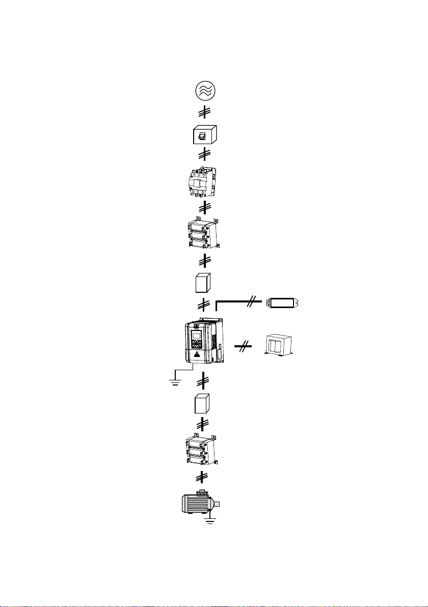
Three-phase AC power supply
MCCB
Contactor
Controller
Ground connection
Connection with peripheral devices
AC input reactor
EMI filter
EMI filter
AC output reactor
Motor
DC reactor
Braking resistor
(optional)
(optional)
Ground connection

CONTENTS
Chapter 1 Safety Information and Precautions ............................................................................ 1
1.1 Safety Definiti on ............................................................................................................... 1
1.2 About Motor and Load ...................................................................................................... 1
1.3 Installation Limitation ........................................................................................................ 2
Chapter 2 Product Information ...................................................................................................... 3
2.1 Model Explanation ............................................................................................................ 3
2.2 Nameplate ....................................................................................................................... 3
2.3 Specifications ................................................................................................................... 4
2.4 Ratings............................................................................................................................. 6
2.5 Parts of Controller ............................................................................................................ 7
Chapter 3 Mechanical Installation ................................................................................................. 9
3.1 Instal la tion Prec autions .................................................................................................... 9
3.2 Requirement for the Installation Site ................................................................................. 9
3.3 Installation Direction and Space Requirements ............................................................... 10
3.4 Dimensions and Mounting Size ...................................................................................... 10
3.5 Panel Installation and Dismantle ..................................................................................... 12
3.6 Plastic C over Disma ntle ................................................................................................. 13
Chapter 4 Electrical Installation .................................................................................................. 15
4.1 Wiring Precautions ......................................................................................................... 15
4.2 Selection of Main Ci rcuit Per ipheral Devices ................................................................... 16
4.3 Main Circuit Terminals and Wiring ................................................................................... 16
4.3.1 Terminals Description......................................................................................... 17
4.3.2 Wiring Terminals ................................................................................................ 17
4.4 Control Terminals and Wire Connection .......................................................................... 18
4.4.1 Control Terminal Description .............................................................................. 19
4.4.2 Wire Jumper De s crip tion .................................................................................... 20
4.4.3 SCI Communicati on Terminal Description .......................................................... 20
4.4.4 Control Terminal Connection .............................................................................. 21
4.5 I/O Terminals and Wiring Connection .............................................................................. 26
4.5.1 I/O Card Terminal Description ............................................................................ 26
4.5.2 I/O Card Wire Jumper Description ...................................................................... 27
4.5.3 I/O Card Terminal Connection ............................................................................ 27
4.6 Encoder Card ................................................................................................................. 28
4.6.1 Encoder Cards Introduction ............................................................................... 28

4.6.2 FD Description ................................................................................................... 28
4.6.3 DB15 Terminal ................................................................................................... 29
4.6.4 HD-PG2-OC-FD ................................................................................................ 29
4.6.5 HD-PG5-SINCOS-FD ........................................................................................ 32
4.6.6 HD-PG6-UVW-FD .............................................................................................. 34
4.6.7 HD-PG9-SC-FD ................................................................................................. 36
4.7 Meet EMC Requirement of Installation ............................................................................ 37
4.7.1 Correct E MC In stallation .................................................................................... 37
4.7.2 Wiring Requirement ........................................................................................... 38
4.7.3 Wiring Motor ...................................................................................................... 38
4.7.4 Ground Connections .......................................................................................... 39
4.7.5 EMI Filter ........................................................................................................... 39
4.7.6 Conduction, Radiation and Radio Frequency Interference Countermeasures ..... 40
4.7.7 Input and Output R eactor ................................................................................... 41
Chapter 5 Operation Instructions ................................................................................................ 43
5.1 Function Description ....................................................................................................... 43
5.1.1 Operation Mode ................................................................................................. 43
5.1.2 Control Mode ..................................................................................................... 44
5.1.3 Controller Sta te .................................................................................................. 44
5.1.4 Controller Running Mode ................................................................................... 44
5.2 Operating Instructions .................................................................................................... 45
5.2.1 Panel Description .............................................................................................. 45
5.2.2 Display State ..................................................................................................... 46
5.2.3 Panel Operation Exa mple s ................................................................................ 48
5.3 Initial Power On .............................................................................................................. 52
Chapter 6 Function Introduction ................................................................................................. 53
6.1 Group D: Display Parameters ......................................................................................... 54
6.1.1 Group D00 System State Par ameters ................................................................ 54
6.1.2 Group D01 Drive State Parameters .................................................................... 55
6.1.3 Group D02 Analogue State Display Parameters ................................................. 56
6.1.4 Group D03 Running State Parameters ............................................................... 57
6.1.5 Group D04 Encode r State Para meters ............................................................... 58
6.2 Group F: General Function Parameters .......................................................................... 59
6.2.1 Group F00 Basic Parameters ............................................................................. 59
6.2.2 Group F01 Protection of Pa rameters .................................................................. 61
6.2.3 Group F02 Start & Stop Parameters .................................................................. 62

6.2.4 Group F03 Acceleration/Deceleration Parameters .............................................. 63
6.2.5 Group F04 Analogue Curve Parameters ............................................................ 64
6.2.6 Group F05 Speed Para mete rs ........................................................................... 65
6.2.7 Group F06 Weighin g C ompensation Param eters ............................................... 67
6.2.8 Group F07 Asynchrono us Motor Parameters...................................................... 68
6.2.9 Group F08 Motor Vector Control Speed-loop Param eters ................................... 71
6.2.10 Group F09 Current-loop Parameters ................................................................ 72
6.2.11 Group F10 Synchronous M ot or Parameters ..................................................... 72
6.2.12 Group F11 PG Parameters............................................................................... 73
6.2.13 Group F12 Di gital I/O Terminal Param eters ...................................................... 74
6.2.14 Group F13 Analo gue I/O Terminal Parameters ................................................. 77
6.2.15 Group F14 SCI Communication Parameters .................................................... 79
6.2.16 Group F15 Display Control Parameters ............................................................ 79
6.2.17 Group F16 Enhance Function Parameters ....................................................... 81
6.2.18 Group F17 Fa ult Protect Paramet ers ................................................................ 82
6.2.19 Group F18 PWM Parameters ........................................................................... 85
6.2.20 Group F19 Reserved ....................................................................................... 85
6.2.21 Group F20 Reserved ....................................................................................... 85
6.3 Group Y Manufacturer Func tio n Para me ter s ................................................................... 85
Chapter 7 Elevator Application Guidance ................................................................................... 87
7.1 Basic Debug Procedures ................................................................................................ 87
7.1.1 System Analy sis and Wire.................................................................................. 87
7.1.2 Set Basic Parameters ........................................................................................ 87
7.1.3 Motor Parameter Auto-tuning ............................................................................. 88
7.1.4 Inspection Running ............................................................................................ 92
7.1.5 Run Fast ............................................................................................................ 92
7.2 Terminal MS Run Mode Application ................................................................................ 93
7.2.1 Control Part Connection ..................................................................................... 93
7.2.2 Set Parameter ................................................................................................... 94
7.3 T erminal Analogue Run Mode Application ....................................................................... 96
7.3.1 Control Part Connection ..................................................................................... 96
7.3.2 Set Parameter ................................................................................................... 97
7.4 Power-off Battery Driven Run Mode Application .............................................................. 98
7.4.1 Basic Connection ............................................................................................... 98
7.4.2 Running Time Sequence .................................................................................... 98

Chapter 8 Troubleshooting .......................................................................................................... 99
Chapter 9 Maintenance .............................................................................................................. 103
9.1 Daily Maintenance ........................................................................................................ 104
9.2 Periodical Maintenance ................................................................................................ 104
9.3 Replacing Damaged Parts ............................................................................................ 105
9.4 Unwanted Controller Recycling ..................................................................................... 105
Chapter 10 Accessories ............................................................................................................. 107
10.1 Panel Installation Assembly ........................................................................................ 107
10.1.1 Mounting Base ............................................................................................... 107
10.1.2 Extension Cable ............................................................................................ 107
10.2 Braking Resistor Selectio n .......................................................................................... 108
10.3 Protect ive Cover ......................................................................................................... 108
10.4 Power Regenerative Unit ............................................................................................ 108
Appendix A Parameters ............................................................................................................. 109
Appendix B Communication Protocol ...................................................................................... 129

Communication Protocol
Elevator A pplicat ion Guidan ce
Troubleshooting
Maintenance
Accessories
Safety Information and Precautions
Product Information
Mechanical Installation
Electrical Installation
Operation Instructions
Function Introduction
Parameters
1
2
3
4
5
6
7
8
9
10
A
B

Shenzhen Hpmont Technology Co., Ltd Chapter 1 Safety Inform a ti on a nd Prec a uti ons
A Danger contains information which is critical for avoiding safety
a
Danger
Warning
Note
Chapter 1 Safety Information and Precautions
1.1 Safety Definition
Danger:
hazard.
Warning: A Warning contains information w hich is essential for avoiding
risk of damage to product or other equipments.
Note: A Note contains inf ormation wh ich helps t o ensure co rrect oper ation
of the product.
1.2 About Motor and L oad
Compared to the standar d frequency operation
The HD5L series controllers are voltage-type controllers and their output is PWM wave with
certain harmonic wave. T herefore, the temperature, noi se and vibration of the motor will be a little
higher than that at standard frequency operation.
Motor’s overload protecting threshold
When choose the adaptive motor, the controller can effectively implement the motor thermal
protection. Otherwise it must adjust the motor protection parameters or other protection
measures to ensure t hat the mot or is at a safe a nd reliab le operation.
Lubrication of mechanical devices
At long time low-speed operation, it should provide periodical lubrication maintenance for the
mechanical devices such as gear box and geared motor etc. to make sure the drive results meet
the site need.
Check the insulation of the motor
For the first time using of the motor or after long time storage, it need check the insulation of the
motor to avoid damage the controller because of the worse insulation motor.
Note:
Please use a 500V Mega-Ohm-Meter to tes t and the in s u lation resistanc e m ust be higher than
5Mohm.
1
HD5L Series Controller User Manual ―1―
Chapter 1 Safety Inform a ti on a nd Prec a uti ons S he nzhen Hpmont Technology Co., Ltd
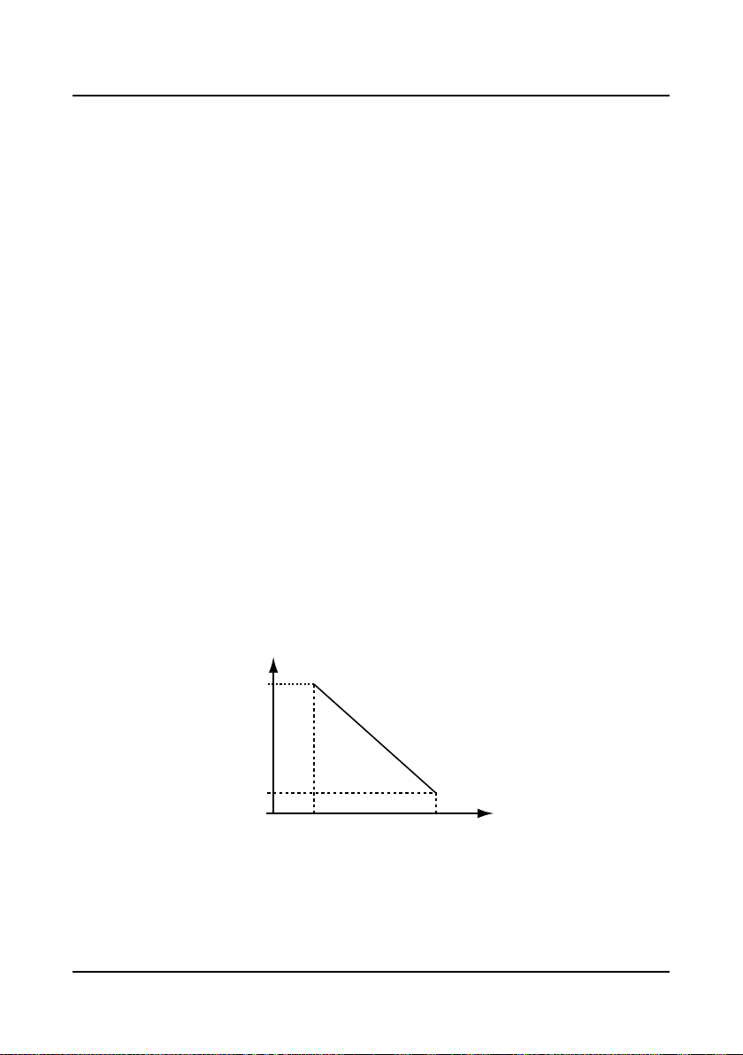
80%
100%
1000 4000
Controller’s rat ed cu r r ent
Altitude(m)
1.3 Installation Limitation
No capacitor or varistor on the output side
Since the controller outpu t is PWM wave, it is strictly forbidden to connect capacitor for improving
the power factor or varistor for lightning protection to the output terminal s so as to avoid the
controller fault tripping or component damage.
Contactors and circuit breakers connect e d t o the out put of t he controller
If circuit breaker or contactor needs to be connected between the controller and the motor, be
sure to operate these circuit breakers or contactor when the controller has no output, so as to
avoid any damage to the controller.
Rated voltage
The controller i s prohibited to be us ed bey ond the speci fied range o f oper ation voltage. If need ed,
please use the suitable voltage regulation device to change the vol tage.
Change three-phase input to single-phase input
For three-phase input controller, the users should not change it to be single-phase input.
If you have to use s ingle-phase power supply, you should disable the in put phase-loss protection
function. And the bus-voltage and current ripple will increase, which n ot only influences the life of
electrolytic capacitor but also deteriorates the performance of the controller. In that case, the
controller must be derating and should be within the controller 60% rated value.
Lightning surge protection
The controller internal design has lightning surge overcurrent protection circuit, and has certain
self-protection capacity against the lightning.
Altitude and derating
In the altitude exceeded 1000 meters area, since the heatsink efficiency will be reduced because
of the tenuous air, the controller should be derating. Figure 1-1 is the derating curve of the
controller rated current and the altitude.
Figure 1-1 Derating curve of controller rated current and altitude
―2― HD5L Series Controller User Manual
Shenzhen Hpmont Technology Co., Ltd Chapter 2 Product Information
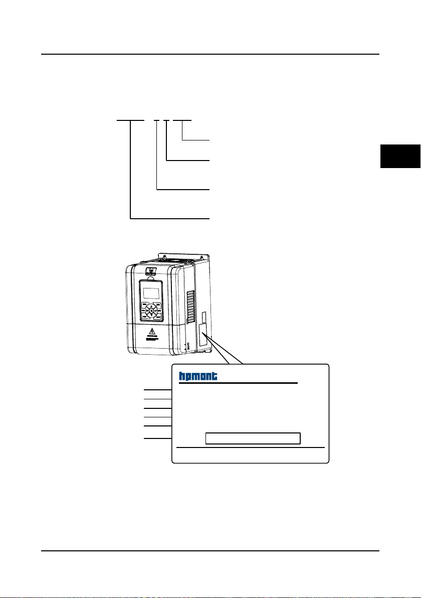
HD5L - 4 T 5P5
2 : 200-240V
4 : 380-460V
Refer to section 2.4 about rati ng
S : single-phase
T : three-phase
Elevator c ontroller
Adaptive motor power
Input phases
Voltage ratings
Product seri es
Shenzhen Hpmont Technology Co., Ltd
HD5L-4T5P5
MODEL:
POWER:
INPUT:
OUTPUT:
Version:
S/N:
5.5kW
3PH380-460V15A50/60Hz
1.00
8.5kVA0-460V 13A0-100Hz
Barcode
Productmodel
Adaptivemotor
Inputspecification
Outputspecification
Softwareversion
Serialnumber
Chapter 2 Product Information
2.1 Model Explanation
2.2 Nameplate
2
HD5L Series Controller User Manual ―3―
Chapter 2 Product Information Shenzhen Hpmont Technology Co., Ltd
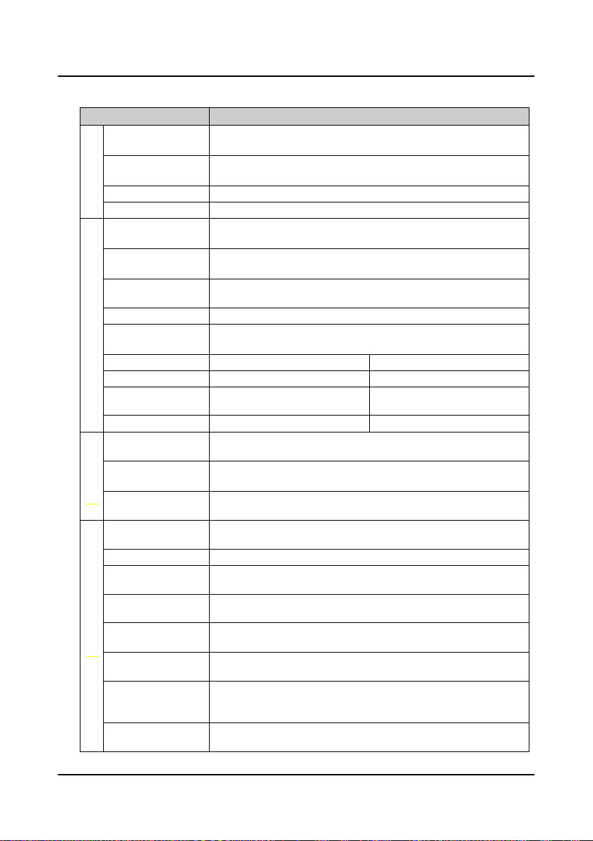
2.3 Specifications
Item Specification
Rated voltage and
frequency
Electrical
Accuracy
Output voltage 0-input voltage
Output frequency 0-100.00Hz
Maximum current
Control mode
Operation command
Performance
control mode
Speed setting mode Digital setting, analogue setting, SCI communication setting
Speed setting
resolution
Speed control accuracy SVC: ± 0.5% VC: ± 0.05%
Speed control range SVC: 1:100 VC: 1:1000
Torque control
response
Start torque SVC: 180% rated-torque /0.5Hz VC: 200% rated-torque /0Hz
Parameter upload and
Characteristic
download function
Programmable I/O
interface
Communication
protocol
Auto-inspection
Over-speed protection To make sure safe running, elevator over-speed protection is provided
Speed deviation
protection
Up/down forced
Protection
deceleration function
I/O phase loss
protection
Motor temperature
detection
Power output
grounding fault
protection
Power output short
circuit protection
Single-phase: 200-240V, 50/60Hz
Three-phase: 380-460V, 50/60Hz
Voltage: fluctuation within ± 10%, imbalance rate < 3%
Frequency: ± 5%
150% rated output current for 2 minutes
180% rated output current for 10 seconds
V/f control; Open-loop vector control (SVC);
Closed-loop vector control (VC)
Panel control; external terminal control; host computer communication
control via SCI communication port
Digital setting: 0.01Hz
Analogue setting: 0.1% × max-frequency
SVC: < 200ms VC: < 50ms
To achieve parameters uploading or downloading
The programmable input interface has up to 34 functions
The pragrammable output interface has up to 19 functions
Controller is built-in MODBUS communication protocol
To eliminate the potential safety problems, safety inspection for the
peripheral devices is provided when power is on
To eliminate the potential safety problems, speed deviation detection
protection is provided
Up/down forced deceleration function, to avoid climbing elevator or plunging
elevator
I/O phase loss auto-detect and alarm function
Real time detection for the motor temperature
Power output grounding fault protection is enabled
Power output short circuit protection is enabled
―4― HD5L Series Controller User Manual

Shenzhen Hpmont Technology Co., Ltd Chapter 2 Product Information
cation
Item Specification
Analogue supply
Digital supply +24V, maximum current 200mA
I/O feature
Analogue input
Analogue output AO1, AO2: 0-10V/0-20mA (voltage/current is selectable)
Digital input DI1-DI6 (control board); DI7-DI12 (I/O card)
Digital output DO1, DO2
Programmable relay
output
Communi-
SCI communication RS-485 interface
+10V, maximum current 100mA
-10V, maximum current 10mA
AI1 (control board): voltage 0-10V
AI2, AI3 (control board): -10V-+10V/0-20mA (voltage/current is
selectable)
AI4 (I/O card): -10V-+10V/0-20mA (voltage/current is selectable, and
differential input is supported)
R1A/R1B/R1C (control board)
R2A/R2B/R2C; R3A/R3B/R3C; R4A/R4B/R4C (I/O card)
Contact rating 250VAC/3A or 30VDC/1A
2
Panel
LCD display
Parameter copy To achieve quick parameter copy
Operation temperature
Environment
Storage temperature -40-+70℃
Location for use
Altitude Less than 1000 meters, otherwise should be derating use
Humidity Less than 95%RH, non-condensing
Ocsillation Less than 5.9m/s2 (0.6g)
Encoder card
Options
About panel
Enhanced protection Protective cover (HD-CK-Frame4)
Power unit Power regenerative unit (HDRU)
Function parameter setting, check the state parameters and the fault code
etc.
-10-+40℃, air temperature fluctuation is less than 0.5℃/min
The derating value of the output current of the controller shall be 2% for each
degree centigrade above 40℃. Max. allowed temperature is 50℃
Indoor, preventing from direct sunlight, no dust, corrosive, flammable gases,
oil mist, water vaper, dripping or salt etc.
OC encoder card with frequency demultiplication output (HD-PG2-OC-FD)
SINCOS encoder card with frequency demultiplication output
(HD-PG5-SINCOS-FD)
Line drive encoder card with frequency demultiplication output
(HD-PG6-UVW-FD)
Serial Communication encoder card with frequency demultiplication output
(HD-PG9-SC-FD) (support Endat)
Mounting base to panel (HD-KMB)
1 meter extension cable to panel (HD-CAB-1M)
2 meter extension cable to panel (HD-CAB-2M)
3 meter extension cable to panel (HD-CAB-3M)
6 meter extension cable to panel (HD-CAB-6M)
HD5L Series Controller User Manual ―5―
Chapter 2 Product Information Shenzhen Hpmont Technology Co., Ltd
(kVA)
(A)
(A)
(kW)
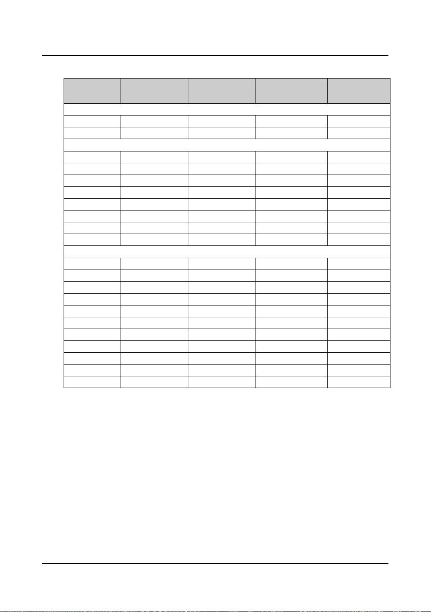
2.4 Ratings
Model
HD5L-2S2P2 3.8 24.1 10 2.2
HD5L-2S3P7 5.9 40 17 3.7
HD5L-2T3P7 5.9 19 17 3.7
HD5L-2T5P5 8.5 28 25 5.5
HD5L-2T7P5 11 35 32 7.5
HD5L-2T011 16 47 45 11
HD5L-2T015 21 62 55 15
HD5L-2T018 24 77 70 18.5
HD5L-2T022 30 92 80 22
HD5L-2T030 39 113 110 30
HD5L-4T2P2 3.4 7.3 5.1 2.2
HD5L-4T3P7 5.9 11.9 9.0 3.7
HD5L-4T5P5 8.5 15 13 5.5
HD5L-4T7P5 11 19 17 7.5
HD5L-4T011 16 28 25 11
HD5L-4T015 21 35 32 15
HD5L-4T018 24 39 37 18.5
HD5L-4T022 30 47 45 22
HD5L-4T030 39 62 60 30
HD5L-4T037 49 77 75 37
HD5L-4T045 59 92 90 45
Rated capacity
Single-phase power supply: 200-240V, 50/60Hz
Three-phase power supply: 200-240V, 50/60Hz
Three-phase power supply: 380-460V, 50/60Hz
Rated input current
Rated output current
Motor power
―6― HD5L Series Controller User Manual
Shenzhen Hpmont Technology Co., Ltd Chapter 2 Product Information
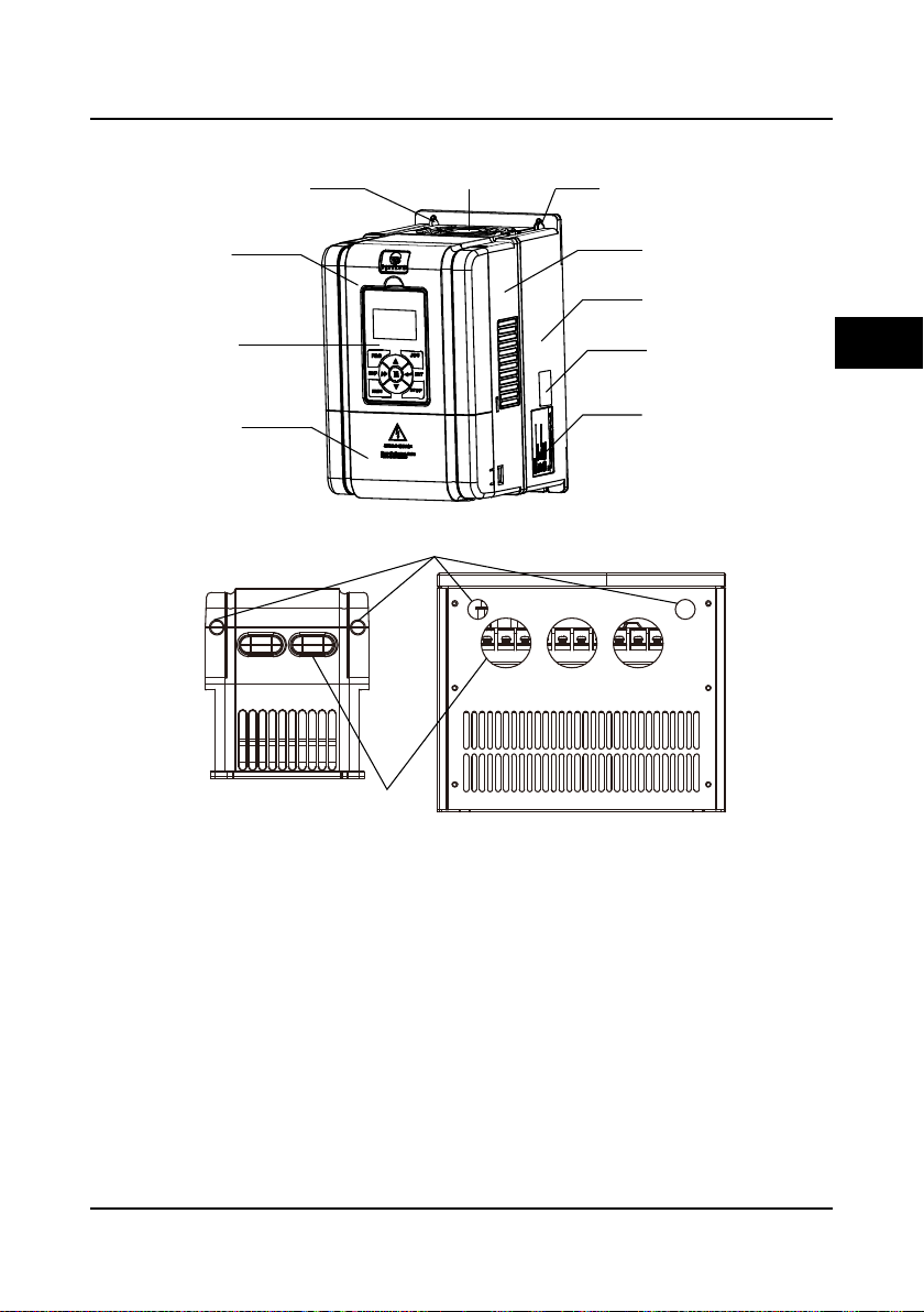
Mountinghole
Certification
Bottomenclosure
Middleenclosure
Displaypanel
Uppercover
Fancover
Lowercover
Mountinghole
Nameplate
Controlterminalconnectionhole
Plastic structure Metal structure
Powerterminal
connectionhole
2.5 Parts of Controller
2
HD5L Series Controller User Manual ―7―
Chapter 2 Product Information Shenzhen Hpmont Technology Co., Ltd
PE
BR
P1
(+)
(-)
U
V W
MOTOR
L1
L2
L3
POWER
I/O card
Refer to section4.5
Control board
Refer to section4.4
Encoder card
(optional)
Refer to section4.6
―8― HD5L Series Controller User Manual
Shenzhen Hpmont Technology Co., Ltd Chapter 3 Mechanical Installation
Danger
Warning
Chapter 3 Mechanical Installation
3.1 Installation Precautions
• Do not install if the controller is imcomplete or impaired.
• Make sure that the controller is far from the explosive and combustible things.
• Do not operate the controller until the power is cut-off 10 minutes later.
• It is required not only carry the panel and the cover but also the controller bottom enclosure.
• Do not play metal into the controller when insta l ling.
123
3.2 Requirement for the Installation Site
Ensure the installation site mee ti ng the foll ow ing requirements:
• Do not instal l at the direc t sunlight, moisture, water droplet location;
• Do not install at the combustible, explosive, corrosive gas and liquid location;
• Do not install at the oily dust, fiber and metal powder location;
• Be vertical installation on fire-retardant material with a strong support;
• Make sure adequate cooling space for the controller so as to keep the ambient temperature
between - 10-+ 40℃;
• Install at where the vibration is less than 5.9m/s
Note:
1. It needs derating use if the controller operation temperature excee ds 40℃ . The derating value
of the output current of the controller shall be 2% for each degree centigrade. Max. allowed
temperature is 50℃.
2. Keep ambient temperature between -10-+40℃. It can improve the controller operation
perform ance if install at the location with good ventilation or cooling devices.
2
(0.6g).
3
HD5L Series Controller User Manual ―9―
Chapter 3 Mechanical Installation Shenzhen Hpmont Technology Co., Ltd
≥30
≥50
≥30
≥50
W
H
H2
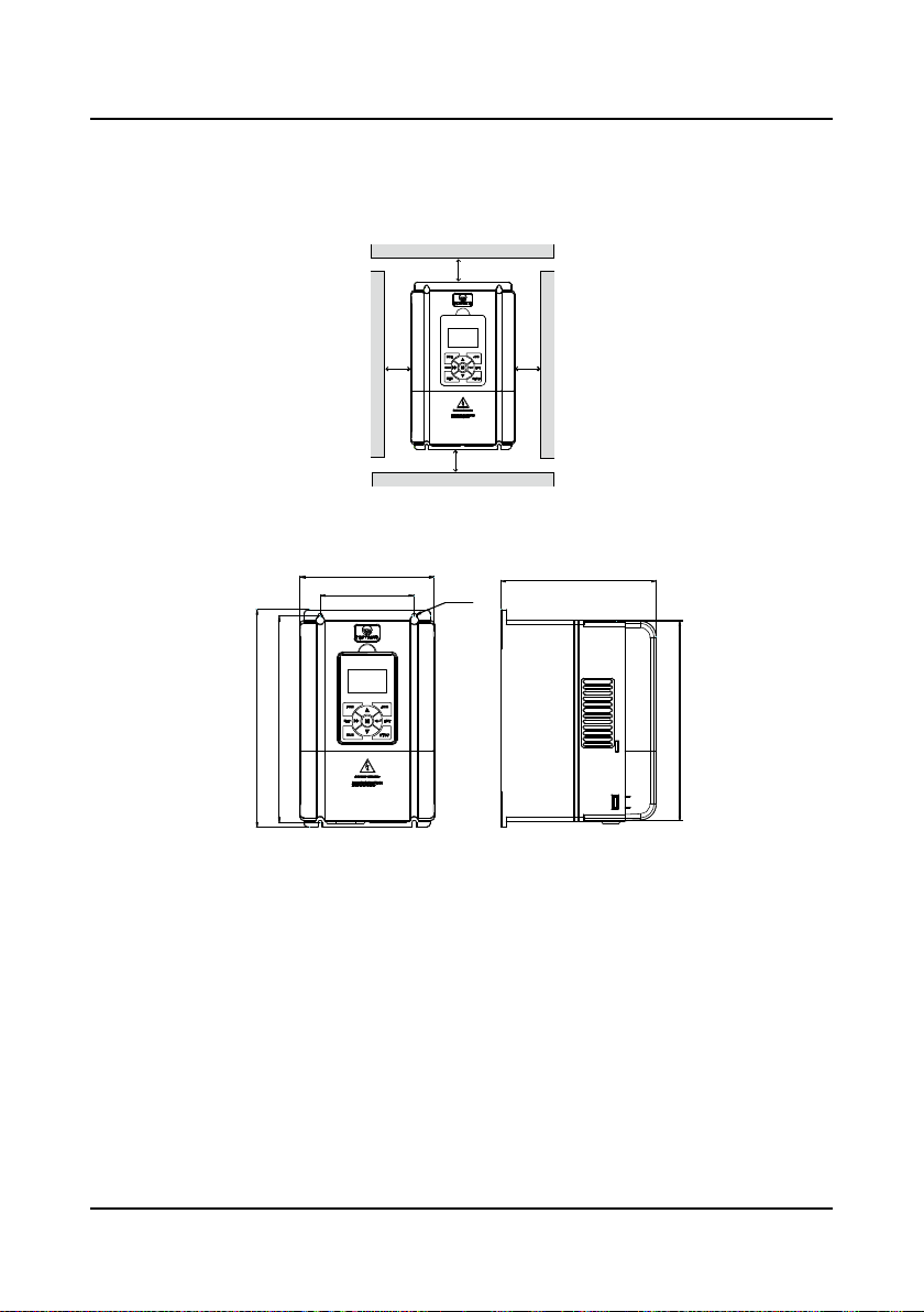
3.3 Installation Direction and Space Requirem ent s
To achieve good cooling efficiency, install the controller perpendicularly and always provide the
following space to allow normal heat dissipation. The requirements on mounting space and
clearance are shown in Figure 3-1.
Figure 3-1 Installation of the controller
3.4 Dimensions and Mounting Size
W1
H1
4-Ød
Dimensions figure 1
D
―10― HD5L Series Controller User Manual
Shenzhen Hpmont Technology Co., Ltd Chapter 3 Mechanical Installation
W
H
H2
W1
4-Ød
D
H1
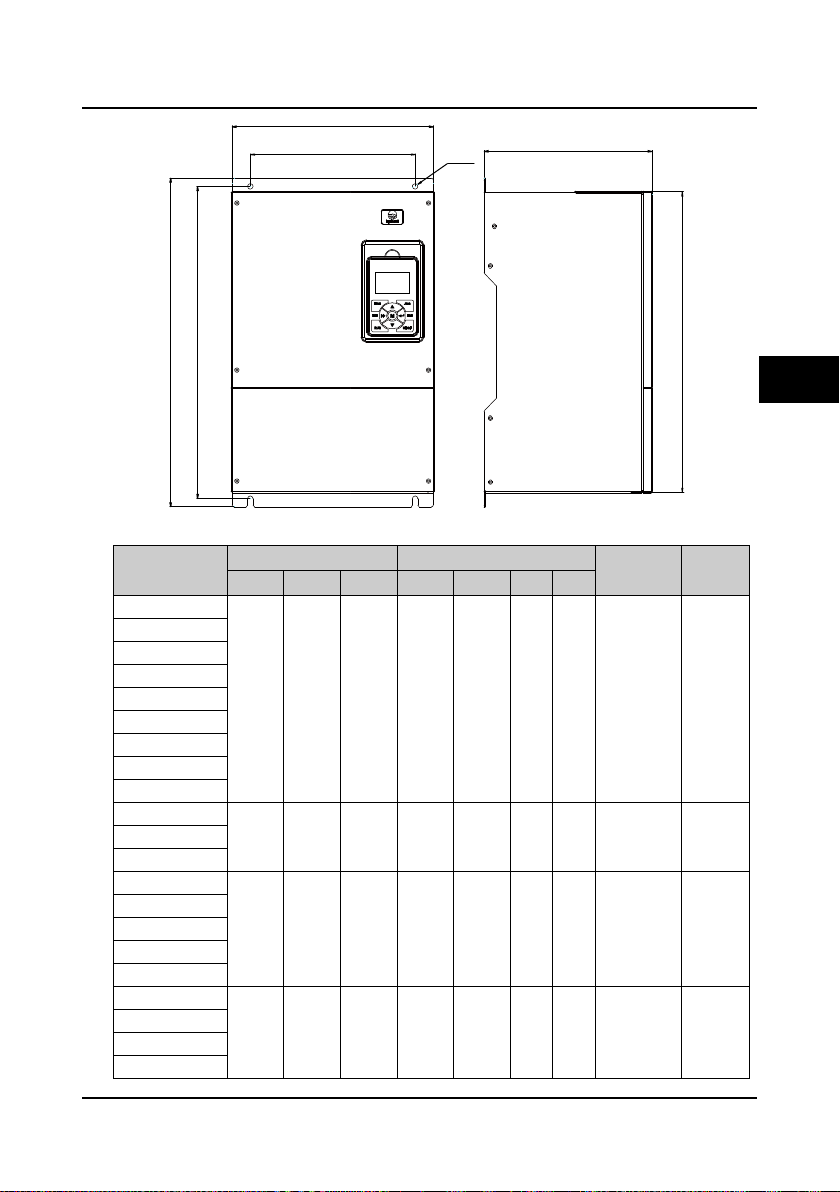
3
(kg)
Figure
Dimensions figure 2
Table 3-1 HD5L dimensions
Model
HD5L-2S2P2
HD5L-2S3P7
HD5L-2T3P7
HD5L-2T5P5
HD5L-4T2P2
HD5L-4T3P7
HD5L-4T5P5
HD5L-4T7P5
HD5L-4T011
HD5L-2T7P5
HD5L-4T015
HD5L-4T018
HD5L-2T011
HD5L-2T015
HD5L-2T018
HD5L-4T022
HD5L-4T030
HD5L-2T022
HD5L-2T030
HD5L-4T037
HD5L-4T045
Dimensions (mm) Mounting size (mm)
W H D W1 H1 H2 d
200 299 210 146 286 280 5 5.8 1
235 353 222 167 337 330 7 8.2 1
290 469 240 235 445 430 8 20.4 2
380 598 290 260 576 550 10 48 2
Gross weight
HD5L Series Controller User Manual ―11―
Chapter 3 Mechanical Installation Shenzhen Hpmont Technology Co., Ltd
ENT
JOG
PRG
RUN
STOP
SHF
ENT
JOG
PRG
RUN
STOP
SHF
1
2
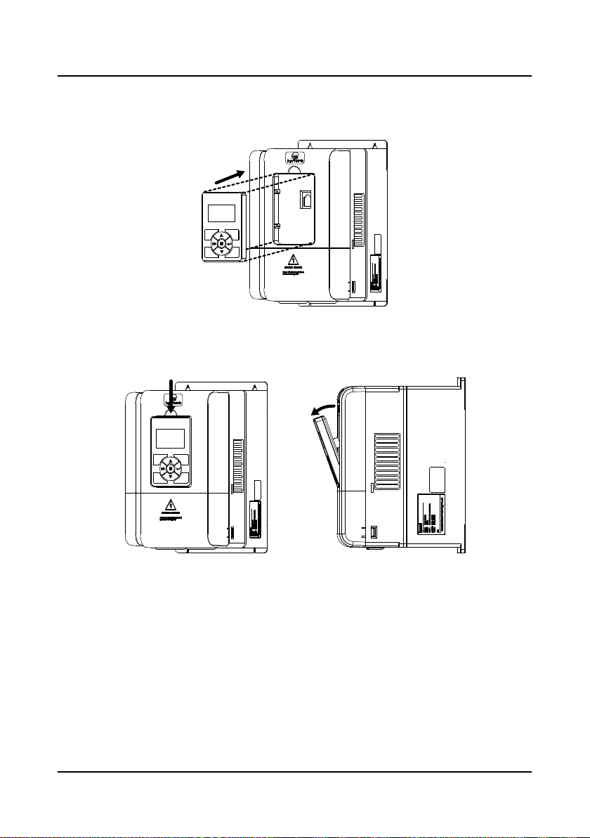
3.5 Panel Installation and Dismant l e
According to the direction of the Figure 3-2, press the panel until hear a “click” sound. Do not
install the panel from other dir ections or it wil l cause p oor contact.
Figure 3-2 Installation of the panel
There are two steps in Figure 3-3.
First, press the hook of the panel according to the direction 1.
Second, take out of the panel according to the direction 2.
Figure 3-3 Dismantle of the panel
―12― HD5L Series Controller User Manual
Shenzhen Hpmont Technology Co., Ltd Chapter 3 Mechanical Installation
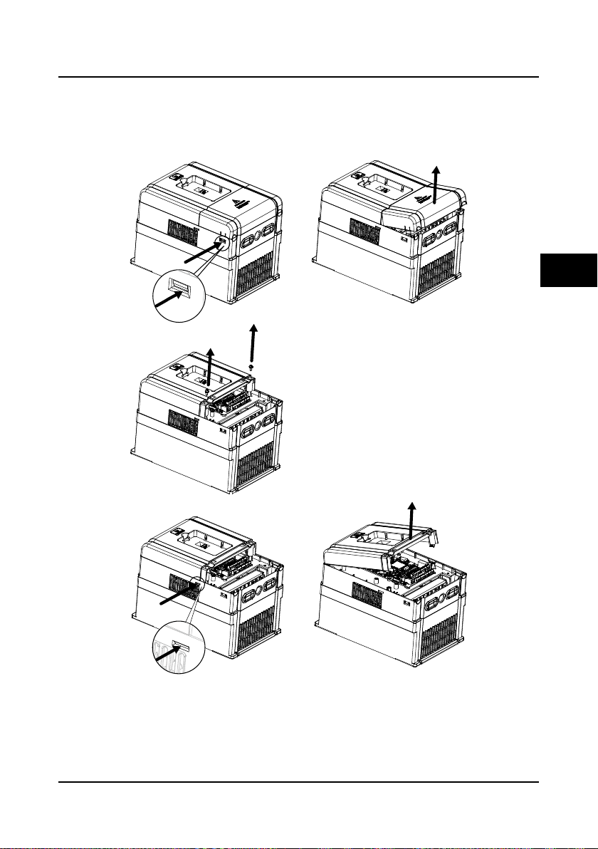
(a)
1.Extrude the hooks at both side together,
take off the lower cover, as (a).
2.Dismantle the screws of upper cover, as (b).
3.Extrude the hooks at both side together,
take off the upper cover, as(c).
The removing proceeses
of plastic coverboard:
(b)
(c)
3.6 Plastic Cover Dismantle
The upper cover and the lower cover of the HD5L series controller are removable. The dismantle
step is shown as Figure 3-4.
Before removing the upper cover, please take away the panel.
3
Figure 3-4 Dismantle of the plastic cover
HD5L Series Controller User Manual ―13―

Shenzhen Hpmont Technology Co., Ltd Chapter 4 Electrical Installation
Danger
Warning
Chapter 4 Electrical Installat ion
4.1 Wiring Precautions
• Only qualified electrical engineer can perform wiring job.
• Only when the power supply switch is completely off can you do the wiring job.
• You can’t open the controller cover to do wiring operation until the power is cut-off 10 minutes later. Do
not wire or detach the controller internal devices at power-on situation.
• Do not do wiring operation until the internal charge indicator of the controller is off and the voltage
between (+) and (-) of the main circuit terminals is below 36V.
• Check the wiring carefully before connecting emergency stop or safety circuit.
• The earth terminal PE of the controller must be reliable earthing. It must use two separate earth wire due
to the leakage current from the controller to ground.
• It must use Type B mode when utilize earth leakage protection devices(ELCB/RCD).
• Do not touch the wire terminals of the controller when it is live. The main circuit terminals is neither
allowed connecting to the enclosure nor short-circuiting.
• Do not do dielectric strength test on the controller.
• Do wiring connection of the braking resistor or the braking unit according to the wiring figure.
• Make sure the terminals are fixed tightly.
• Do not connect the AC supply cable to the output terminals U/V/W of the controller.
• Do not connect the phase-shifting capacitors to the output circuit.
• The controller DC bus terminals must not be short-circuited.
4
HD5L Series Controller User Manual ―15―
Chapter 4 Electri c al I ns tallation Shenzhen Hpmont Technology Co., Ltd
Danger
Warning
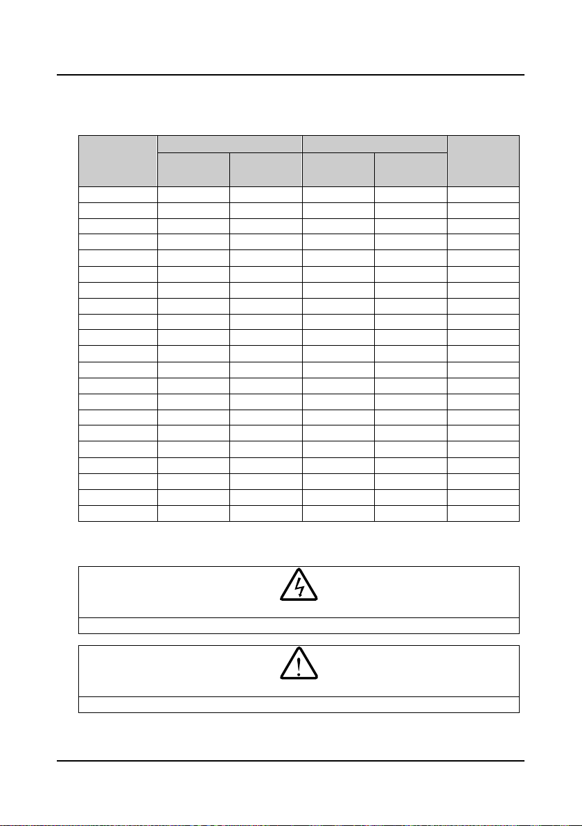
4.2 Selection of Main Circuit Peripheral Devices
Please r efer to the Table 4-1 for the recommended specification s.
Table 4-1 HD5L series controller I/O wiring specification
Input Protection Main Circuit
Model
HD5L-2S2P2 32 20 4.0 2.5 ≥0.5
HD5L-2S3P7 63 32 4.0 4.0 ≥0.5
HD5L-2T3P7 40 32 4.0 4.0 ≥0.5
HD5L-2T5P5 63 40 6.0 6.0 ≥0.5
HD5L-2T7P5 63 40 6.0 6.0 ≥0.5
HD5L-2T011 100 63 16 16 ≥0.5
HD5L-2T015 125 100 25 25 ≥0.5
HD5L-2T018 160 100 25 25 ≥0.5
HD5L-2T022 200 125 35 35 ≥0.5
HD5L-2T030 200 125 50 50 ≥0.5
HD5L-4T2P2 16 10 1.5 1.5 ≥0.5
HD5L-4T3P7 25 16 2.5 2.5 ≥0.5
HD5L-4T5P5 32 25 4.0 4.0 ≥0.5
HD5L-4T7P5 40 32 4.0 4.0 ≥0.5
HD5L-4T011 63 40 6.0 6.0 ≥0.5
HD5L-4T015 63 40 6.0 6.0 ≥0.5
HD5L-4T018 100 63 10 10 ≥0.5
HD5L-4T022 100 63 16 16 ≥0.5
HD5L-4T030 125 100 25 25 ≥0.5
HD5L-4T037 160 100 25 25 ≥0.5
HD5L-4T045 200 125 35 35 ≥0.5
MCCB
(A)
Contactor
(A)
Supply Cables
(mm2)
Motor Cables
(mm2)
Control Circuit
(mm2)
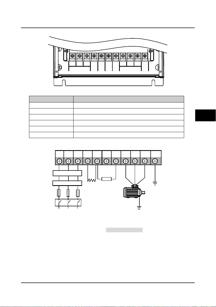
4.3 Main Circuit Terminals and Wiring
• The bare portions of the power cables must be bound with insulation tapes.
• Ensure that AC supply voltage is the same as controller’s rated input voltage.
―16― HD5L Series Controller User Manual
Shenzhen Hpmont Technology Co., Ltd Chapter 4 Electri c al I ns tallation
MOTOR
PE
L3
L1 L2
W
U V
P1
L1 L2 L3 (+) (-) BR U V W PE
P1
Optional EMIfilter
Optional ACreactor
Mains supply
Braking resistor
Fuses
DC reactor
(external)
Supply ground
4.3.1 Terminals Description
(+) (-)
POWER
BR
Figure 4-1 Power terminal layout of HD5L controller
Table 4-2 HD5L power terminal function description
Terminal Function Description
L1、L2、L3 Three-phase AC power input terminals
U、V、W Output terminals, connect to three-phase AC motor
P1、(+) DC reactor connection terminals
(+)、(-) DC supply input terminals; DC input terminals of power regenerative unit
(+)、BR Braking resistor connection terminals
PE Earth terminal, connect to the ground
4.3.2 Wiring Terminals
Figure 4-2 HD5L power terminal connection
During trial operation, make sure that the elevator will go up when the UP command is enabled.
If the elevator goes down, set the parameter F00.08 (run direc tion) to be the reverse value.
4
HD5L Series Controller User Manual ―17―

Chapter 4 Electri c al I ns tallation Shenzhen Hpmont Technology Co., Ltd
Danger
Warning
SCI communicationterminal
Wirejumper
CN5andCN6
WirejumperCN9
Controlterminal
Wirejumper
CN7 andCN8
4.4 Control Terminals and Wire Connection
• The control circuit is designed as ELV (Extra Low Voltage) circuit and basically isolated with the
power circuit. Do not touch the control circuit when the controller is on power.
• If the control circuit is connected to the external devices with live touchable port (SELV circuit), it
should increase an additional isolating barrier to ensure that SELV classification of external devices
not be changed.
• If connect the communication terminal of the control circuit to the PC, you should choose the
RS485/232 isolating converter which meets the safety requirement.
In order to efficiently suppress the interference to control signals, the length of signal cables
should be less than 50m and keep a distance of at least 0.3m from the power lines. Please use
twisted-pair shie lded cable s for analogue input and output signals.
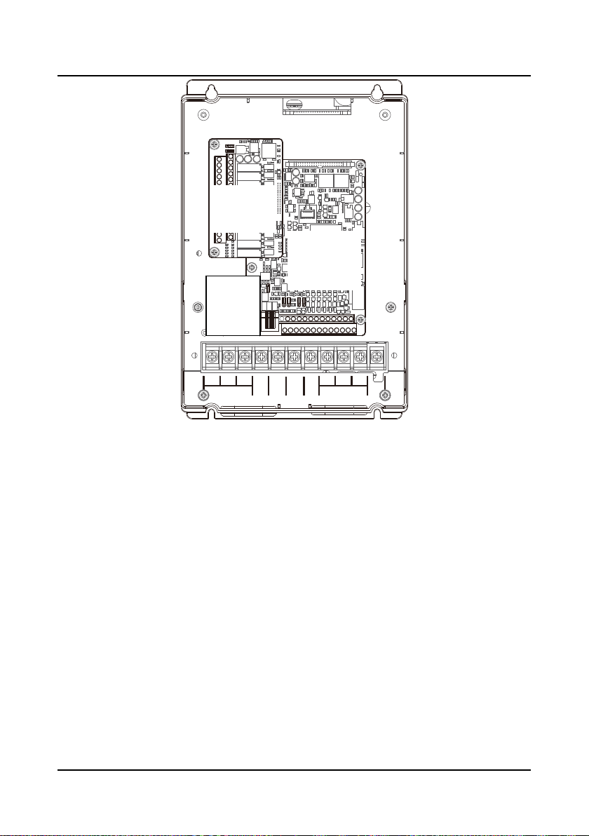
The positions of control terminal, wire jumper and SCI commu nicati on port in the control board
are shown in Figure 4-3.
Figure 4-3 Positions of control terminal, wire jumper and SCI port in the control board
―18― HD5L Series Controller User Manual
Shenzhen Hpmont Technology Co., Ltd Chapter 4 Electrical Install a ti on
+10
-10
AI1 AI2
AI3
DI1 DI2 DI3 DI4 DI5 DI6 COM R1ACOM
GND
AO1 AO2
P24 SEL DO1 R1C
GND COM CME DO2 R1B
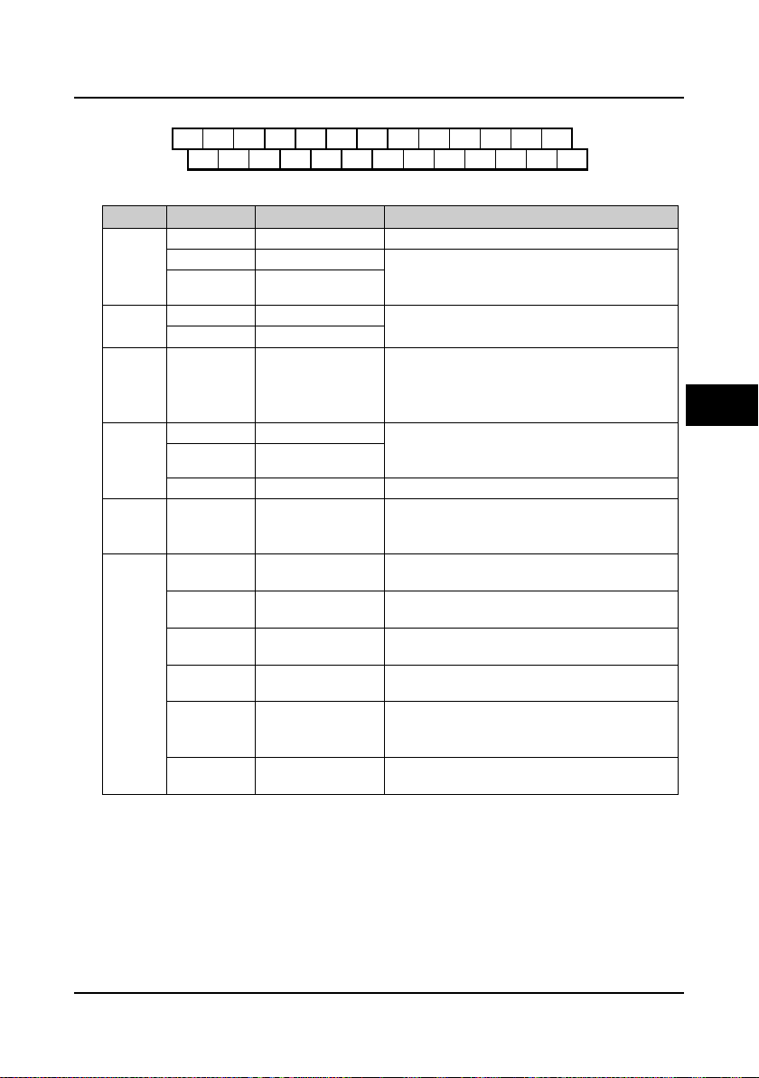
4.4.1 Control Terminal Description
Figure 4-4 Control terminal layout
Table 4-3 Control terminal function description
Item Terminal Name Function Description
AI1 Anglogue input 1 Input voltage: 0-10V (input impedance: 34kΩ)
Analogue
input
Analogue
output
Digital
input
Digital
output
Relay
output
Power
source
AI2 Anglogue input 2 Input voltage/current is selectable;
AI3 Anglogue input 3
AO1 Anglogue output 1
AO2 Anglogue output 2
DI1-DI6 Digital input 1-6
DO1 Digital output 1 Programmable optical-coupled isolation, open
DO2 Digital output 2
CME DO1 reference ground Isolated from COM, default short connected COM
R1A/ R1B/ R1C Relay contact output
+10V +10V power supply
-10V -10V power supply
GND
P24 +24V power supply
SEL
COM
+/-10V power
reference ground
Digital input common
terminal
Digital reference
ground
Input voltage: -10V-10V (input impedance: 34kΩ);
Input current: 0-20mA (input impedance: 500Ω)
Output voltage/current signal: 0-10V/0-20mA;
Programmable output
Programmable bipolar optional input signal
Input voltage: 0-30VDC
DI1-DI5 input impedance: 4.7kΩ;
DI6 input impedance: 1.6kΩ
collector output
Output voltage: 0-30VDC, max-output current 50mA
Programmable output, contact rating: 250VAC/3A or
30VDC/1A
R1B,R1C: normally closed; R1A,R1C: normally open
Analogue input use +10V as reference supply,
maximum output current is 100mA
Analogue input use -10V as reference supply,
maximum output current is 10mA
Analogue site, isolated from COM
Digital input use +24V as supply, maximum output
current is 200mA
Factory settings default SEL and P24 are connected.
Disconnected SEL and P24 when use external power
to drive DI1-DI6
Digital site, isolated from CME
4
HD5L Series Controller User Manual ―19―
Chapter 4 Electri c al I ns tallation Shenzhen Hpmont Technology Co., Ltd
CN5
1
3
CN6
1
3
CN7
1
3
CN8
1
3
CN9
13
Port pin
Port signal
RJ45
1
+5V2485+3+5V4GND5GND6GND7485-8Reserved
1 8
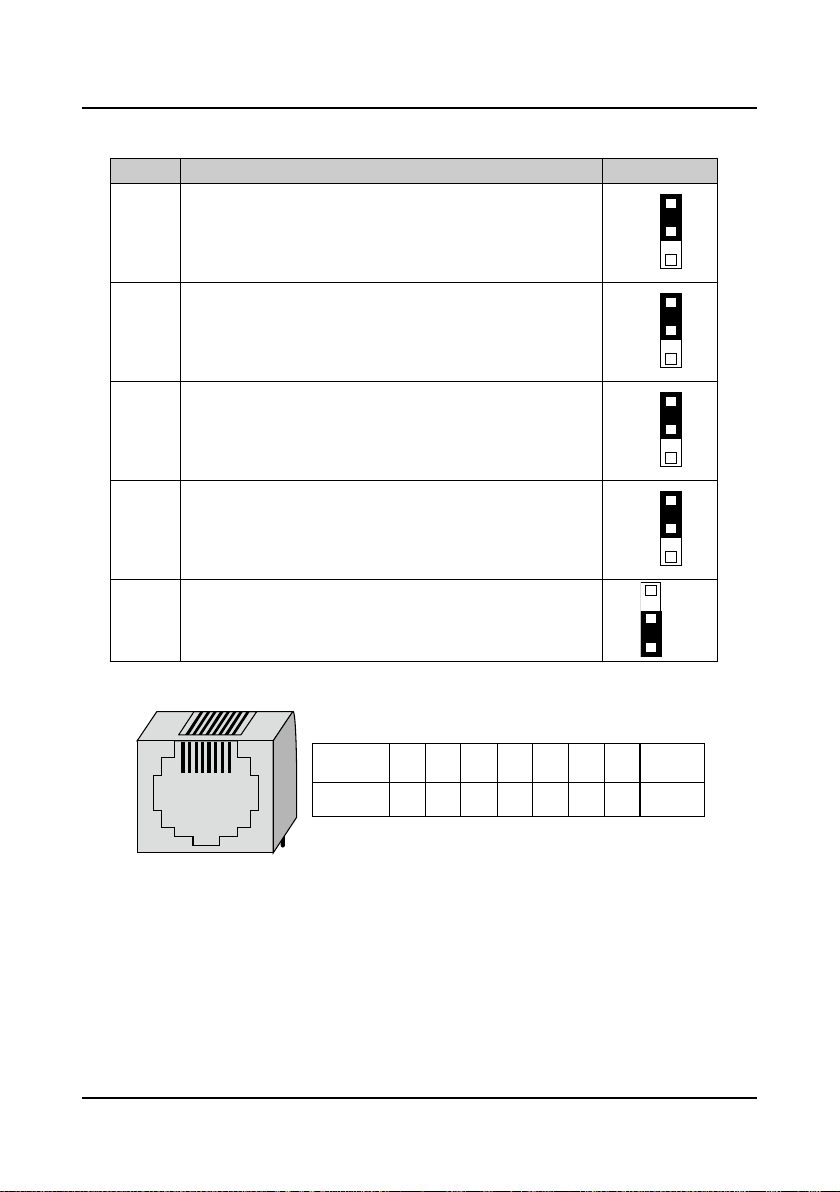
4.4.2 Wire Jumper Description
Table 4-4 Wire jumper function and setting description on the control board
Jumper Function and setting description Factory setting
AI2 analogue input channel can select voltage or current signal.
When pin 1 and pin 2 of the CN5 are short-circuited, AI2 channel
CN5
inputs voltage signal;
When pin 2 and pin 3 of the CN5 are short-circuited, AI2 channel
inputs current signal.
AI3 analogue input channel can select voltage or current signal.
When pin 1 and pin 2 of the CN6 are short-circuited, AI3 channel
CN6
inputs voltage signal;
When pin 2 and pin 3 of the CN6 are short-circuited, AI3 channel
inputs current signal.
AO1 analogue output channel can select voltage or current signal.
When pin 1 and pin 2 of the CN7 are short-circuited, AO1 channel
CN7
outputs voltage signal;
When pin 2 and pin 3 of the CN7 are short-circuited, AO1 channel
outputs current signal.
AO2 analogue output channel can select voltage or current signal.
When pin 1 and pin 2 of the CN8 are short-circuited, AO2 channel
CN8
outputs voltage signal;
When pin 2 and pin 3 of the CN8 are short-circuited, AO2 channel
outputs current signal.
SCI communication can select proper resistance.
When pin 2 and pin 3 of the CN9 are short-circuited, no resistance;
CN9
When pin 1 and pin 2 of the CN9 are short-circuited, select the proper
resistance.
4.4.3 SCI Communication Terminal Description
Figure 4-5 SCI communication terminal and description
―20― HD5L Series Controller User Manual
Shenzhen Hpmont Technology Co., Ltd Chapter 4 Electri c al I ns tallation
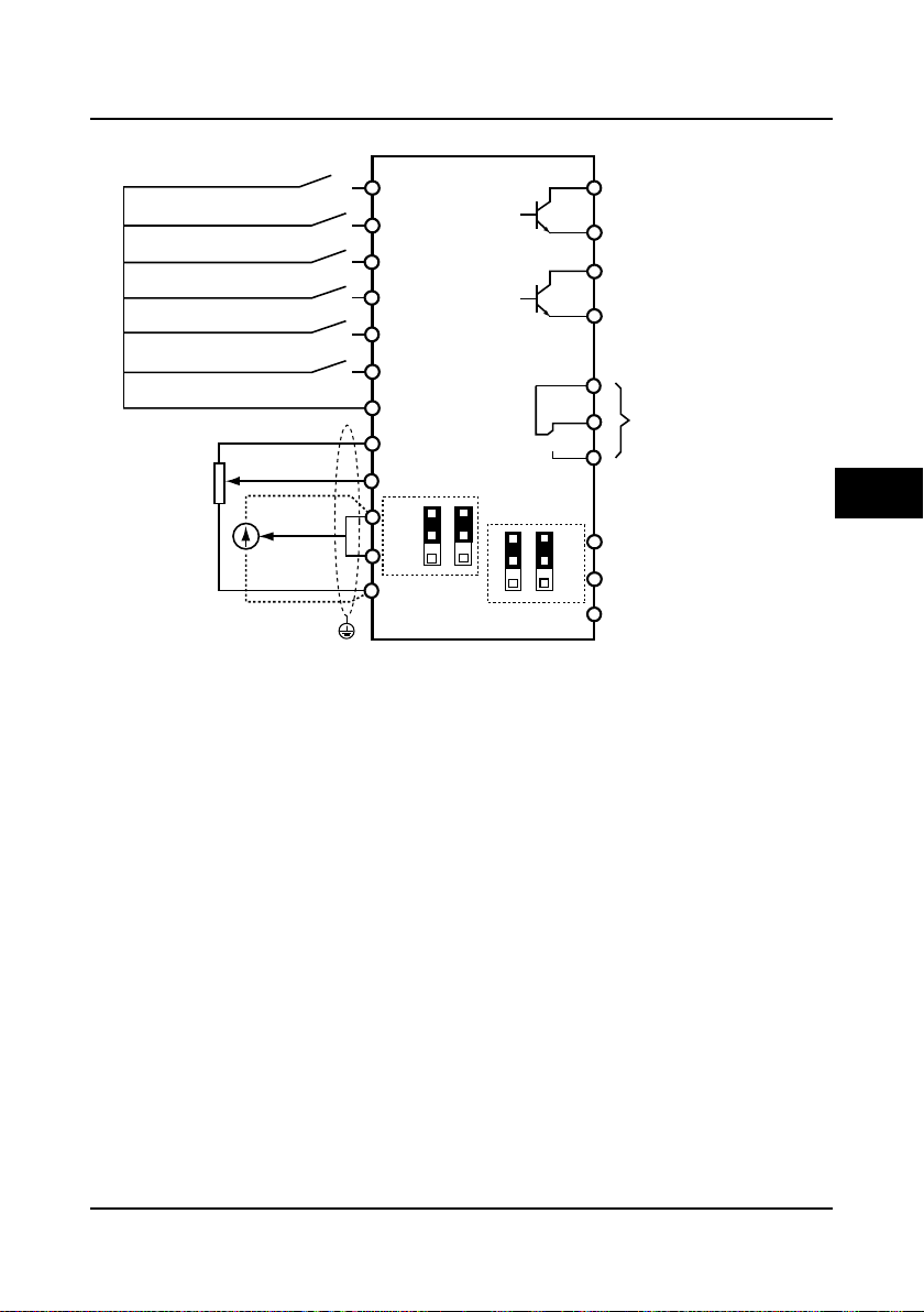
DI1
DO2
DO1
CME
R1A
R1C
R1B
GND
AO1
AO2
DI2
DI3
DI4
DI5
DI6
COM
AI1
AI2
+10
HD5L
Control board
AI3
GND
COM
PE
CN5
1
3
CN6
1
3
CN7
1
3
CN8
1
3
Multi-function inputterminal1
Multi-function inputterminal2
Multi-function inputterminal3
Multi-function inputterminal4
Multi-function inputterminal6
Multi-function inputterminal5
Digital ground
DO1 referenceground
DO2 reference ground
AI 1
AI 2
Analogue ground
Analogue ground
Analogue outputchannel2
Analogue outputchannel1
Programmable relayoutput
Programmable open-collector
output channel1
Programmable open-collector
output channel2
AI
3
Shielded cable
4.4.4 Control Terminal Connection
4
HD5L Series Controller User Manual ―21―
Figure 4-6 HD5L control circuit connection diagram
 Loading...