


HD31 Series
Aqua Inverter
HD31 Series
Aqua Inverter
User Manual
V1.1 2017.07

FOREWORD
Thank you for purchasing HD31 series aqua inverter manufactured by Shenzhen
Hpmont Technology Co., Ltd.
This User Manual describes how to use HD31 series inverters and their installation
wiring, parameter setting, troubleshooting and daily maintenance etc.
Before using the product, please read through this User Manual carefully. In addition,
please do not use this product until you have fully understood safety precautions.
Note:
Preserve this Manual for future.
Due to product upgrade or specification change, and for the purpose of
improving convenience and accuracy of this manual, this manual’s contents may
be modified.
If you need the User Manual due to damage, loss or other reasons, please contact
the regional distributor of our company or directly contact our company Technical
Service Center.
For the first time using, the user should carefully read this manual.
If you still have some problems during use, please contact our company Technical
Service Center.
Email address: overseas_1@hpmont.com
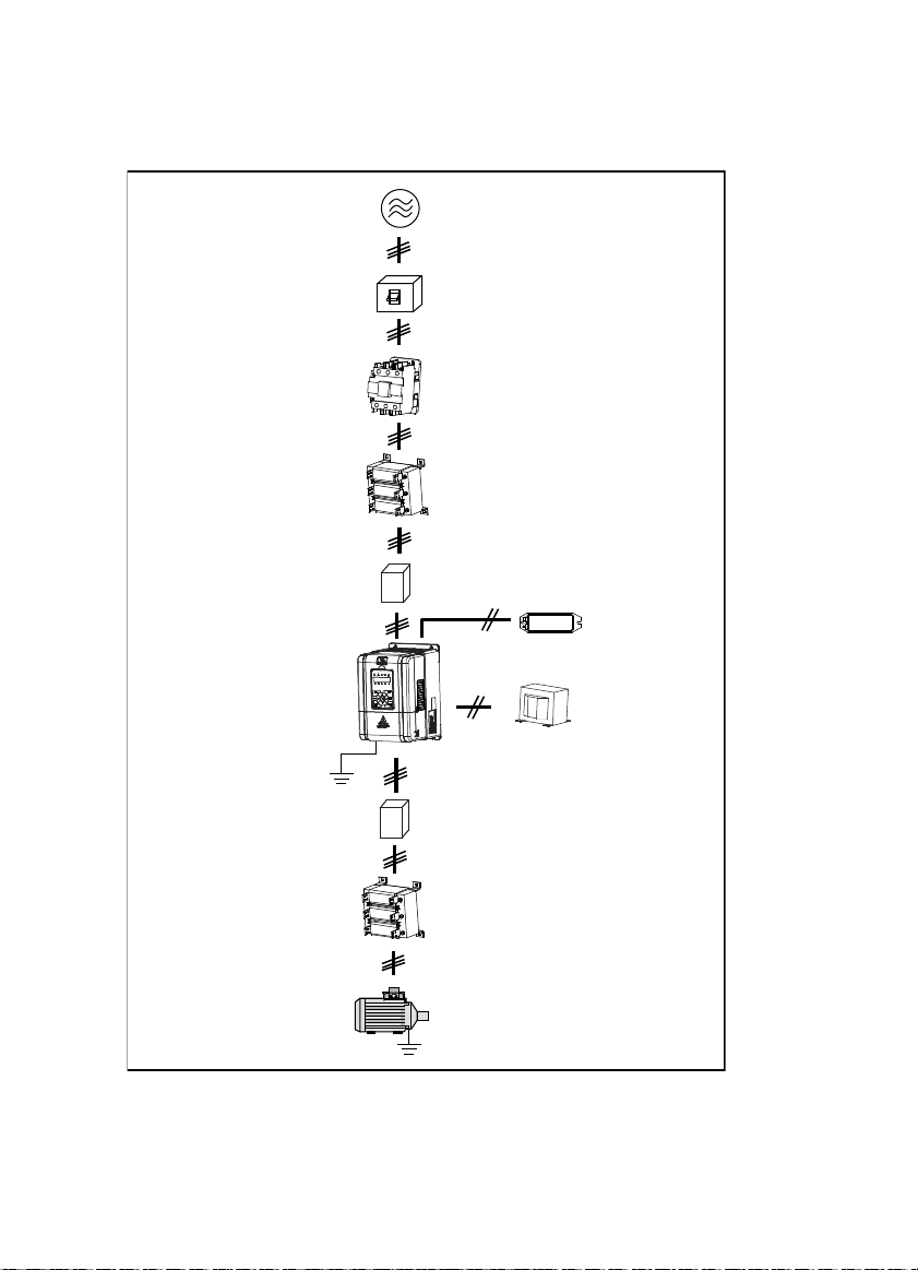
n
n
p
h
Co
ectionwithperi
Three-phase AC power supply
AC input r eactor
eral devices
MCCB
Contactor
(accessory)
EMI filter
Braking resistor
(accessory)
HD31
EMI filter
AC output reactor
(accessory)
Motor
DC reactor
(accessory)

Version and Revision Records
The version information is on top of the backbone and the bottom left of the cover.
Time: 2017/07
Version: V1.1
Revised chapter Revised contents
• New model: HD31-4T2P2P, HD31-4T3P7P
• Refer to 2.3 Rated Value, 4.2.1 Wiring specifications of input and output, 9.3 Braking
Resistor and Braking Unit for details
• Modify the input and output lines, see 4.2.1
• New content: 4.2.2 Power terminal lug.
• Add adjustment in switching from variable frequency to power frequeny, see 7.2
• Add fault: E00.37 (Input wrong phase), see Chapter 8
Chapter 6
Appendix A
• Change the pressure unit to: kg/cm2
• Concrete parameter: P00.05, P02.01, P02.04, P02.06, P02.08, P02.10, P02.12, P02.14, P02.16,
P02.18, P02.20, P02.22, P02.24, P02.26, P04.00, P04.02
• Add d00.42 (Set water supply pressure), d00.43 (Actual water supply pressure)
• Add F00.04 (Extension card selection)
• F15.00 – F15.08 (DI function) add: 54 Clear fault records
• F18.02 – F18.13 (Set parameter of run/stop status) modify:
• Add: 35 (Content water supply pressure setting), 36(Actula feedback pressure)
• F18.04, F18.12, F18.13 modify default
• P00.07 (Dormancy enable) add: 3 (No flow dormancy 1), 4 (No flow dormancy 2)
• Modify defination of P00.13, P00.14
• Add P00.23 – P00.30 ((no-flow power function), P00.31 – P00.38 (function of switching from
variable frequency to power frequency), P00.39 – P00.50 (pump contactor function)
• P02.28 (Proportional gain of pressure closed-loop) modify default and range: 0.00 – 10.00
[0.01]
• Add P02.35 (Digital setting for saving selection when power failure)
• Add P05.03 – P05.04 (pressure sensor function), P05.05 ( Water supply method)


CONTENTS
Chapter 1 Safety Information and Precautions .................................................................................................... 1
1.1 Safety Definition ............................................................................................................................... 1
1.2 About Motor and Load ..................................................................................................................... 1
1.3 About HD31 ....................................................................................................................................... 2
Chapter 2 Product Information ............................................................................................................................... 5
2.1 Model .................................................................................................................................................. 5
2.2 Nameplate .......................................................................................................................................... 5
2.3 Rated Value ........................................................................................................................................ 6
2.4 Technical Data ................................................................................................................................... 6
2.5 Parts of Inverter ................................................................................................................................. 8
Chapter 3 Machenical Installation .......................................................................................................................... 9
3.1 Precautions ........................................................................................................................................ 9
3.2 Installation Site Requirement ......................................................................................................... 9
3.3 Installation Direction and Space Requirements ........................................................................ 10
3.4 Dimensions and Weight ................................................................................................................. 11
3.5 Install and Dismantle Keypad ....................................................................................................... 12
3.6 Dismantle Plastic Cover ................................................................................................................. 13
Chapter 4 Electrical Installation ............................................................................................................................ 15
4.1 Precautions ...................................................................................................................................... 15
4.2 Peripheral Accessories Selection .................................................................................................. 15
4.2.1 Wiring specifications of input and output......................................................................................... 15
4.2.2 Power terminal lug .................................................................................................................................... 16
4.3 Main Circuit Terminals and Wiring ............................................................................................... 16
4.3.1 Supply and Motor Terminal .................................................................................................................... 17
4.3.2 Supply and Motor Connection .............................................................................................................. 18
4.4 Control Board and I/O Board ......................................................................................................... 19
4.4.1 Control Board Terminal ............................................................................................................................ 20
4.4.2 I/O Board Terminal ..................................................................................................................................... 21
4.4.3 Modbus Communication Terminal ...................................................................................................... 21
4.4.4 Jumper ........................................................................................................................................................... 22
Chapter 5 Keypad .................................................................................................................................................... 23
Chapter 6 Function Introduction .......................................................................................................................... 25
6.1 Group d: Display Parameters ........................................................................................................ 26

6.1.1 d00: Status Display Parameters ............................................................................................................. 26
6.2 Group F: General Parameters ........................................................................................................ 29
6.2.1 F00: Basic Parameters ............................................................................................................................... 29
6.2.2 F01: Protection of Parameters................................................................................................................ 32
6.2.3 F03: Acc / Dec Parameters ....................................................................................................................... 33
6.2.4 F05: External Setting Curve Parameters ............................................................................................. 33
6.2.5 F08: Asynchronous Motor Parameters................................................................................................ 35
6.2.6 F09: V/f Control Parameters .................................................................................................................... 36
6.2.7 F15: Digital I/O Terminal Parameters ................................................................................................... 38
6.2.8 F16: Analogue I/O Terminal Parameters ............................................................................................. 41
6.2.9 F17: SCI Communication Parameters .................................................................................................. 43
6.2.10 F18: Display Control Parameters ........................................................................................................ 44
6.2.11 F19: Function-boost Parameters ........................................................................................................ 45
6.2.12 F20: Fault Protection Parameters ....................................................................................................... 47
6.2.13 F23: PWM Control Parameters ............................................................................................................. 50
6.3 Group P: Special Parameter for Multi-pump Water Supply ...................................................... 51
6.3.1 P00: Water Supply Logic Parameter ..................................................................................................... 51
6.3.2 P01: Water Supply Pump Parameter .................................................................................................... 56
6.3.3 P02: Water Supply PID Parameter ......................................................................................................... 57
6.3.4 P03: Water Supply AIO Function Parameter ..................................................................................... 59
6.3.5 P04: Water Supply Fault Protection Parameter ................................................................................ 61
6.3.6 P05: Water Supply Time Parameter ...................................................................................................... 61
Chapter 7 Application Reference .......................................................................................................................... 63
7.1 Take one-to-six inverter as an example. ...................................................................................... 63
7.2 Debugging for Switching between VF and IF ............................................................................ 66
Chapter 8 Troubleshooting ................................................................................................................................... 67
Chapter 9 Accessories ............................................................................................................................................. 71
9.1 Keypad Installation Assembly ...................................................................................................... 71
9.2 Reactor Selection ............................................................................................................................ 71
9.3 Braking Resistor and Braking Unit ............................................................................................... 72
Appendix A Parameters ......................................................................................................................................... 73

Safety Information and Precautions
Product Information
Machenical Installation
Electrical Installation
Keypad
Function Introduction
Application Reference
Troubleshooting
Accessories
Parameters
1
2
3
4
5
6
7
8
9
A

Shenzhen Hpmont Technology Co., Ltd. Chapter 1 Safety Information and Precautions
W
Chapter 1 Safety Information and Precautions
1.1 Safety Definition
Danger
arning
Note
A Danger contains information which is critical for avoiding safety hazard.
Danger:
A Warning contains information which is essential for avoiding a risk of damage to products or other
Warn ing:
equipements.
A Note contains information which helps to ensure correct operation of the product.
Note:
1.2 About Motor and Load
Compared to the industrial frequency running
The HD31 series inverters are voltage-type frequency inverters and their output is PWM wave with
certain harmonic wave. Therefore, the temperature, noise and vibration of the motor will be a little
higher than that at industrial frequency running.
Constant torque at low-speed running
When HD31 drives a standard motor at low-speed running for a long time, the output torque ratings
will become worse due to the motor cooling is less effective. In that case, we suggest that you should
choose variable frequency motor.
Thermal protection of motor
When choose the adaptive motor, HD31 can effectively implement thermal protection of motor.
Otherwise it must adjust the motor protection parameters or other protection measures to ensure that
the motor is at a safe and reliable running.
Running above the rated frequency of motor
If the motor runs exceeding its rated frequency, the noise will increase. Pay attention to the motor
vibration as well as ensure the motor bearings and mechanical devices to meet the requirement of
running speed range.
Lubrication of mechanical devices
At long time low-speed running, provide periodical lubrication maintenance for the mechanical
devices such as gear box and geared motor etc. to make sure the drive results meet the site need.
1
HD31 Series User Manual V1.1 ―1―

Chapter 1 Safety Information and Precautions Shenzhen Hpmont Technology Co., Ltd.
Mechanical resonance point of load
Set the skip frequency (F05.17 - F05.19) to avoid the load device or the motor mechanical resonance
point.
Start and stop HD31
User should use the control terminal to start and stop HD31.
It is strictly forbidden to use contactor or other switches on the input side of HD31 to start and stop
directly, or it will damage the device.
Check the insulation of the motor
For the first time using of the motor or after long time storage, it needs checking the insulation of the
motor. Worse insulation can cause damage to HD31.
Note:
Use a 500V Mega-Ohm-Meter to test and the insulation resistance must be higher than 5Mohm.
Load and negative torque
For the occasion to boost load and the like, negative torque often occurs. Consider setting proper
parameters of the braking unit if HD31 is prone to overcurrent or overvoltage fault trip.
Requirement for leakage current protector RCD
Since the device generates high leakage current which goes through the protective grounding
conductor, please install B type leakage current protector RCD on one side of the power supply.
For the selection of RCD, users need to consider the possible problems of ground leakage current in
both transient status and steady status at start and during running. It is recommended to choose
either special RCD that can suppress the higher harmonics, or general RCD that has more aftercurrent.
Warning for ground mass leakage current
The device generates mass leakage current, so users need to confirm the reliable grounding before
connect to the power supply. The grounding should comply with the local relative IEC standard.
1.3 About HD31
No capacitor or varistor on the output side
Since HD31 output is PWM wave, it is strictly forbidden to connect capacitor for improving the power
factor or varistor for lightning protection to the output terminals so as to avoid HD31 fault trip or
component damage.
Contactors and circuit breakers connected to the output of HD31
If circuit breaker or contactor needs to be connected between HD31 and the motor, be sure to operate
these circuit breakers or contactor when HD31 has no output, so as to avoid any damage to HD31.
Running voltage
HD31 is prohibited to be used beyond the specified range of running voltage. If needed, please use
suitable voltage regulation device to change the voltage.
―2― HD31 Series User Manual V1.1
Shenzhen Hpmont Technology Co., Ltd. Chapter 1 Safety Information and Precautions
Capacitor energy storage
When the AC power supply is cut off, capacitor of HD31 sustains deadly power for a while. So to
disassemble HD31 that is powered, please cut off the AC power supply for more than 10 minutes,
confirm the internal charge indicator is off and the voltage between (+) and (-) of the main circuit
terminals is below 36V.
Generally, the internal circuit enables the capacitor to discharge. However, the discharging may fail in
some exceptions. In these cases, users need to consult Hpmont or our regional distributor.
Lightning surge protection
HD31 internal design has lightning surge overcurrent protection circuit, and has certain self-protection
capacity against the lightning.
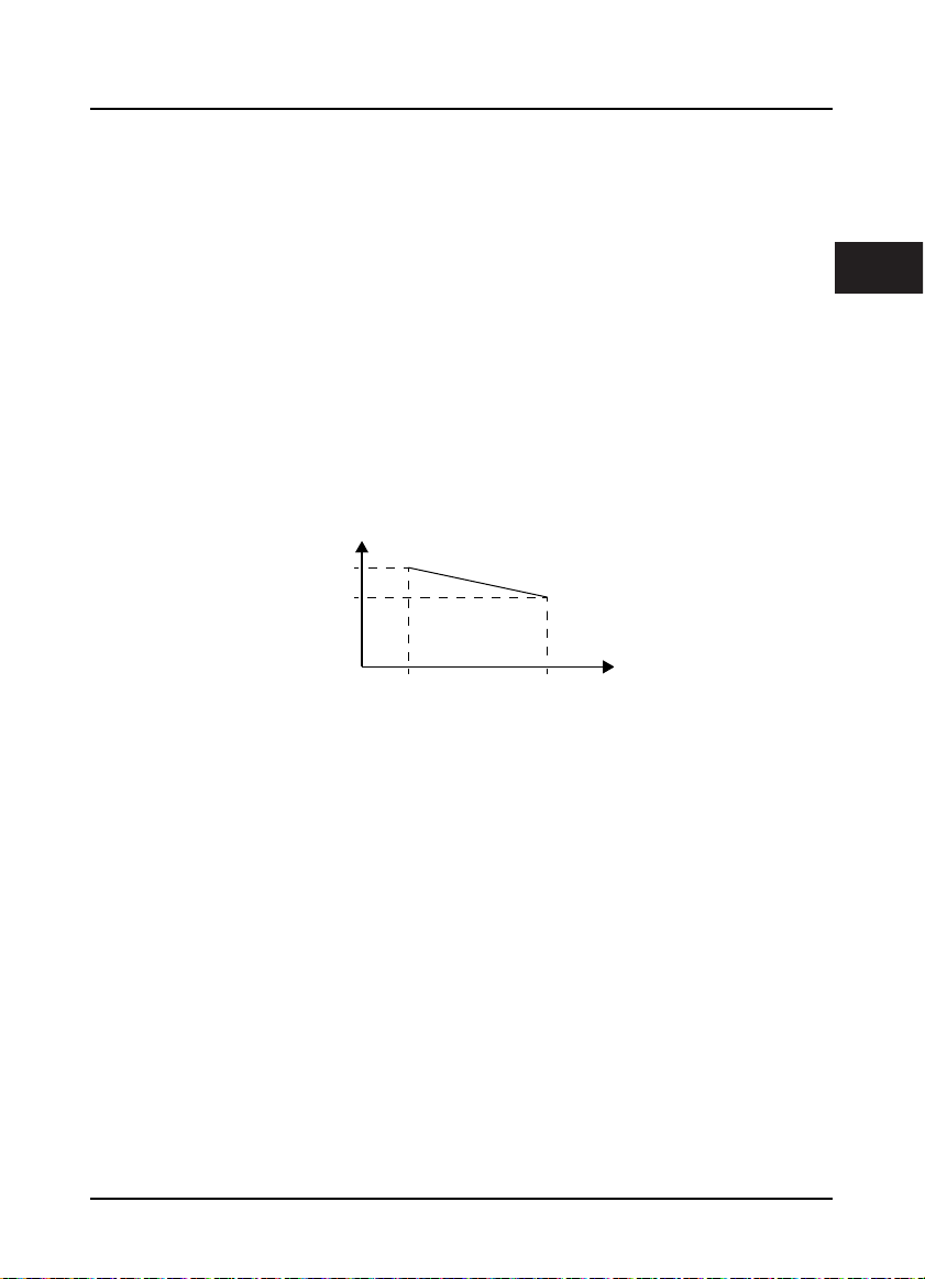
Altitude and derating
In area where altitude exceeds 1000 meters, HD31 should be derating since the heatsink efficiency will
be reduced because of the tenuous air.
The rated value of output current derates by 1% for each 100m increase of the altitude. I.e. for the
altitude of 4000m, derated rate is 30% for rated current of HD31. Figure 1–1 is the derating curve of
rated current and the altitude.
Rated current of HD31
100%
70%
Altitude
1000m 4000m
Figure 1–1 Derating curve of rated current and altitude
1
HD31 Series User Manual V1.1 ―3―

Shenzhen Hpmont Technology Co., Ltd. Chapter 2 Product Information
Chapter 2 Product Information
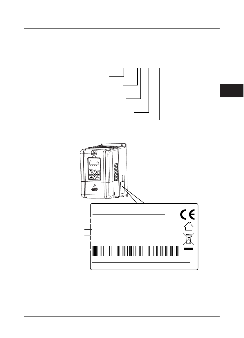
2.1 Model
HD31-4T7P5-P
Product Series
Power Supply Voltage
380 - 460VAC = 4
Input Phase
Three-phase input = T
Power
Product Type
2.2 Nameplate
Fan and pump = P
FWD
REV
ALM
LOCK
LO/RE
HZ
A
V
RPM %
2
Product model
Motor power
Input specification
Output specification
Software version
MODEL:
POWER:
INPUT:
OUTPUT:
HD31-4T7P5P
7.5kW
3PH 380-460V 19A 50/60Hz
11kVA 0-460V 17A 0-400Hz
1.00Version:
Serial number
HD31 Series User Manual V1.1 ―5―
Chapter 2 Product Information Shenzhen Hpmont Technology Co., Ltd.
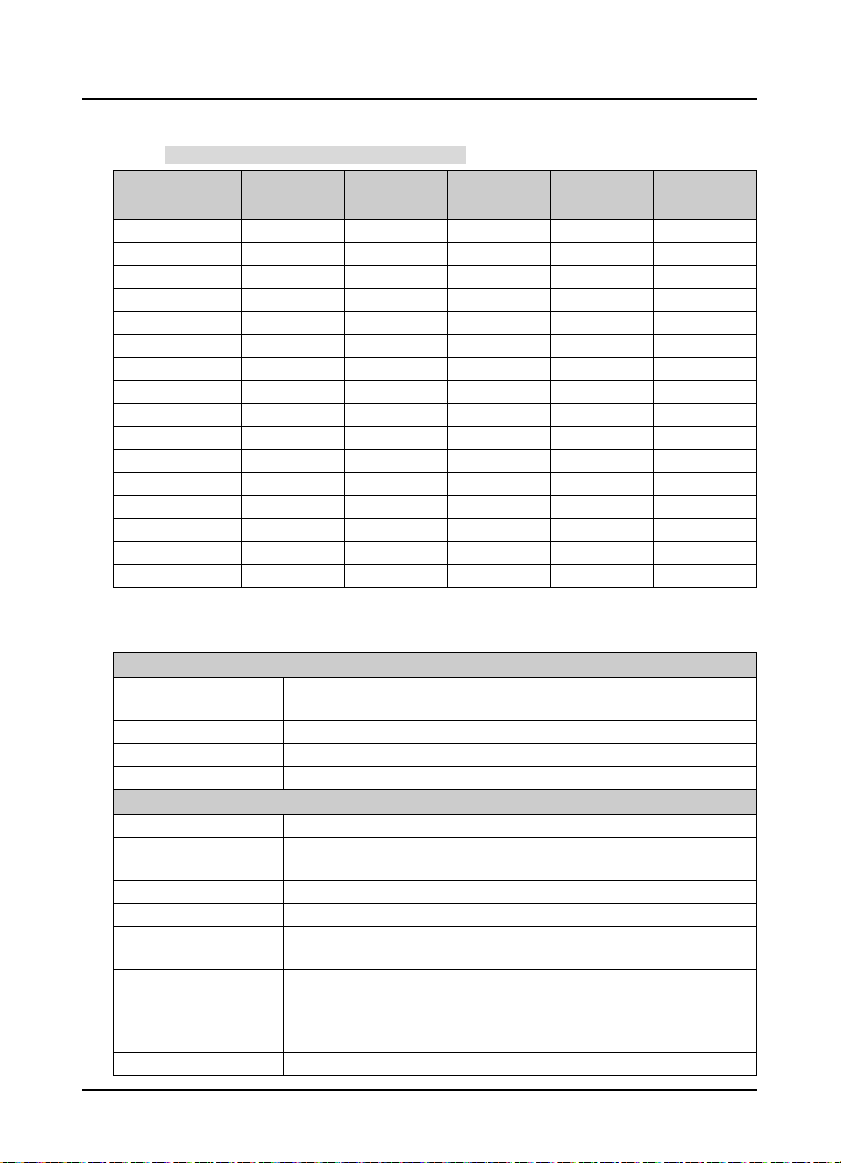
2.3 Rated Value
Refer to section 3.4 Dimensions and Weight (on page 11) for size information.
Model
HD31-4T2P2P 2.2 3.4 7.3 5.1 F2
HD31-4T3P7P 3.7 5.9 11.9 9.0 F2
HD31-4T5P5P 5.5 8.5 15 13 F2
HD31-4T7P5P 7.5 11 19 17 F2
HD31-4T011P 11 16 28 25 F3
HD31-4T015P 15 21 35 32 F3
HD31-4T018P 18.5 24 39 37 F4
HD31-4T022P 22 30 47 45 F4
HD31-4T030P 30 39 62 60 F5
HD31-4T037P 37 49 77 75 F5
HD31-4T045P 45 59 92 90 F6
HD31-4T055P 55 72 113 110 F6
HD31-4T075P 75 100 156 152 F6
HD31-4T090P 90 116 180 176 F7
HD31-4T110P 110 138 214 210 F7
HD31-4T132P 132 167 256 253 F7
Motor
(kW)
Rated Capacity
(kVA)
Rated Input
Current (A)
Rated Output
Current (A)
Size
2.4 Technical Data
Electrical
Input voltage
Input frequency 50/60Hz ± 5%
Output voltage 0 - input voltage
Output frequency 0 - 400.00Hz
Perf orman ce
Control mode V/f, SVC
Max. current
Running command Keypad; Terminals; Communication
Speed setting Digital; Analogue; Communication
Speed resulotion
SVC
Torque control accuracy ±5%
Three-phase: 380 - 460V, 50/60Hz
Fluctuating within ± 10%, imbalance rate < 3%
120% rated output current for 5 minutes;
135% rated output current for 35 seconds
Digital setting: 0.01Hz
Analogue setting: 0.1% × max-frequency
Speed cont rol accuracy: ± 0 .5%
Speed control range: 1:100
Torque control response: < 200ms
Start torq ue: 180% rated torque / 0.5Hz
―6― HD31 Series User Manual V1.1

Shenzhen Hpmont Technology Co., Ltd. Chapter 2 Product Information
Protection Functions
Stall overvoltage Bus voltage can auto-control against overvoltage fault
Auto-limit current protection Output current can auto-limit against overcurrent fault
Overload pre-alarm and
alarm
Load loss protection Load loss alarm function
Input / Output voltage
phase loss protection
Braking fault protection Braking detection and alarming function
PID commands and
feedback loss detection
Power output grounding
fault protection
Power output short circuit
protection
Input / Outpot
Analogue power supply +10V, max. current 100mA
Digital power supply +24V, max. current 200mA
Analogue input
Analogue output AO1, AO2: 0 - 10V/0 - 20mA (selectable voltage/current)
Digital input
Digital output
Relay output
Keypad
LED display
LCD display Optional [HD-LCD], display contents in Chinese or English
Parameter copy Both LED and LCD keypad can achieve quick parameter copy
Communication
SCI communication RS-485 interface; Terminal
Overload early pre-alarm and protect
Input / Output voltage phase loss auto-detec t and alarm function
PID can auto-identify whether loss the setting and feedback or the alarm function
Power output grounding fault protection is enabled
Power output short circuit protection is enabled
AI1 (control board): voltage 0 - 10V
AI2 (control board): -10 - +10V/0 - 20mA (selectable voltage/current)
AI3, AI4 (I/O board): -10 - +10V/0 - 20mA (selectable voltage/cu rrent)
DI1 - DI6 (control board); DI7 - DI9 (I/O board)
DI6 can be selectable for high-frequency input
DO1, DO2
DO2 can be selectable for high-frequency output
R1A/R1B/R1C(control board), R2A/R2C - R10A/R10C(I/O board)
Contact rating: 250VAC/3A or 30VDC/1A
Five LEDs display, 5 unit indicators, 5 status indicators
Setting frequency, output frequency, output voltage, output current, motor speed,
output torque, switching value terminal, status parameter, programm menu
parameter and fault code etc.
2
HD31 Series User Manual V1.1 ―7―
Chapter 2 Product Information Shenzhen Hpmont Technology Co., Ltd.
e
C
C
Environment
Running temperature
Storage temperature -40 - +70℃
Location for use
Altitude Less than 1000 meters, otherwise should be derating use
Humidity Less than 95%RH, non-condensing
Vibration Resistance It is 3.5m/s2 in 2 - 9Hz, it is 10m/s2 (IEC60721-3-3) in 9 - 200Hz
Protection class IP20
Pollution level Level 2 (Dry, non conducting dust pollution)
Accessorie s
Bus communication
About keypad
Power units Dynamic braking unit [HDBU]
-10 - +40℃, max. 50℃, air temperature fluctuation is less than 0.5℃/min
The derating value of the output current of HD31 shall be 2% for each degree
centigrade above 40℃. Max. allowed temperature is 50℃
Indoor, preventing from direct sunlight, no dust, corrosive, flammable gases, oil mist,
water vaper, dripping or salt etc.
PROFIBUS option [HDFB-PROFIBUS-DP]
DeviceNet option [HDFB-DeviceNet]
CAN option [HDFB-CAN]
LCD k eypad ( HD-LCD)
Mounting base to keypad (HD-KMB)
1m/2m/3m/6m extension cable to keypad (HD -CAB-1M/2M/3M/6M)
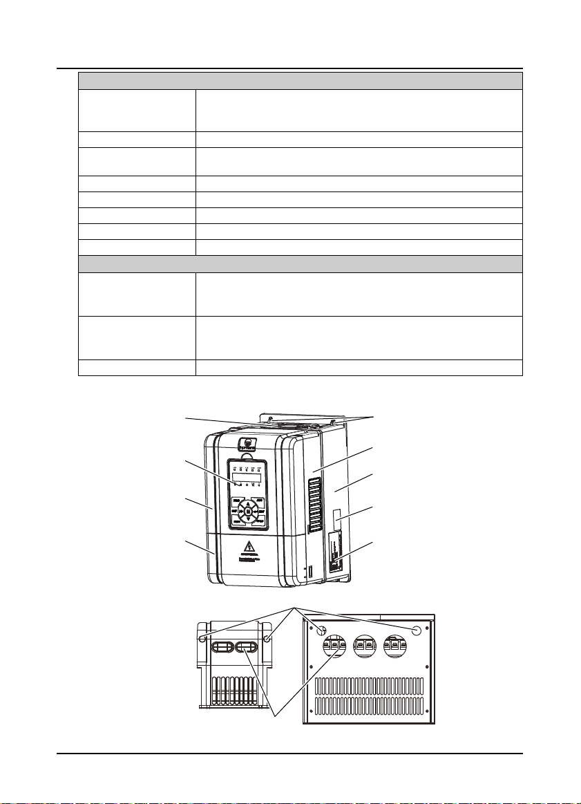
2.5 Parts of Inverter
Fan cover
Keypad
Mounting hole
Middle enclosure
Bottom enclosur
Upper cover
Lower cover
onnection holesofcontrolterminal
Size F2 - F4
onnection holesofpower terminal
Certification
Nameplate
Size F5 - F7
―8― HD31 Series User Manual V1.1
Shenzhen Hpmont Technology Co., Ltd. Chapter 3 Machenical Installation
W
Chapter 3 Machenical Installation
3.1 Precautions
Danger
arning
• Do not install if HD31 is incomplete or impaired.
• When conveying HD31, please employ suitable tools according to its weight. Avoid scratch to the product. Be
careful: rollover and drop may cause hurt.
• Make sure that HD31 is far from explosive and flammable things.
• Do not do wiring operation until power supply is cut off for more than 10 minutes, the internal charge indicator of
HD31 is off and the voltage between (+) and (-) of the main circuit terminals is below 36V.
• It is required not only carry the keypad and the cover but also bottom enclosure of HD31.
• Do not let wires, screws or residues fall into HD31 when installing.
3.2 Installation Site Requirement
Ensure the installation site meets the following requirements:
• Do not install at direct sunlight, moisture, water droplet location;
• Do not install at flammable, explosive, corrosive gas and liquid location;
• Do not install at oily dust, fiber and metal powder location;
• Be vertical installed on fire-retardant material with a strong support;
• Make sure adequate cooling space for HD31 so as to keep ambient temperature between
- 10 - + 40℃;
• Install at where the vibration is 3.5m/s2 in 2 - 9Hz, 10m/s2 in 9 - 200Hz (IEC60721-3-3);
• Install at where the humidity is less than 95%RH and non-condensing location;
• Protection level of HD31 is IP20 and pollution level is 2 (Dry, non-conducting dust pollution).
Note:
1. It needs derating use if running temperature exceeds 40℃. The derating value of the output current of
HD31 shall be 2% for each degree centigrade. Max. allowed temperature is 50℃.
2. Keep ambient temperature between -10 - +40℃. It can improve the running performance if install at
location with good ventilation or cooling devices.
3
HD31 Series User Manual V1.1 ―9―
Chapter 3 Machenical Installation Shenzhen Hpmont Technology Co., Ltd.
D
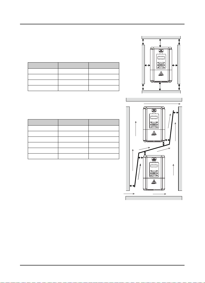
3.3 Installation Direction and Space Requirements
To achieve good cooling efficiency, install the inverter
perpendicularly and always provide the following space to
allow normal heat dissipation. The requirements on mounting
space and clearance are shown in Table 3-1.
Table 3-1 Installation space
HD31 power 5.5 - 75kW 90 - 132kW
A (left and right)
B (up and down)
C (upper vent)
D (lower vent)
123
≥
50mm
≥
100mm
≥
50mm
≥
50mm
≥
150mm
≥
350mm
≥
100mm
≥
100mm
When one inverter is mounted on top of another, an air flow
diverting plate should be fixed between them. Just as shown
in Table 3-2.
Table 3-2 Installation of several inverters
HD31 power 5.5 - 75kW 90 - 132kW
123
A
B
C
a
b
c
≥
≥
≥
≥
≥
≥
50mm
50mm
50mm
50mm
50mm
50mm
≥
100mm
≥
100mm
≥
100mm
≥
100mm
≥
100mm
≥
100mm
C C
B
AA
D
B
a
b
c
C
B
A
―10― HD31 Series User Manual V1.1
Shenzhen Hpmont Technology Co., Ltd. Chapter 3 Machenical Installation
H
H
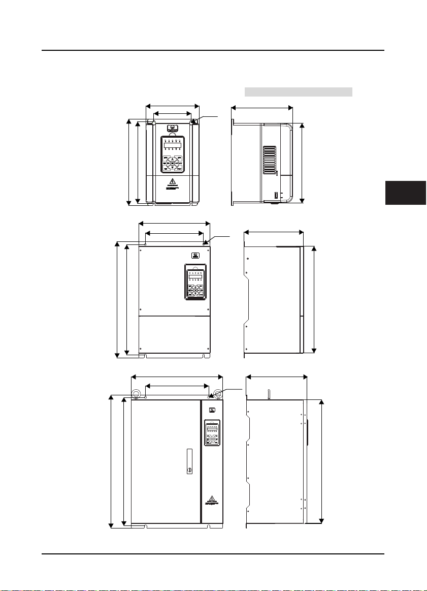
3.4 Dimensions and Weight
The dimensions and weight of HD31 are as shown in Table 3-3.
For the corresponding model of the mounting size, refer to section 2.3 Rated Value, on page 6.
W
W1
4-Ød
D
H1
H1
W
W1
W
W1
Size F2 - F4
4-Ød
Size F5 - F6
H2
3
D
H2
D
4-Ød
H
H1
H2
Size F7
HD31 Series User Manual V1.1 ―11―
Chapter 3 Machenical Installation Shenzhen Hpmont Technology Co., Ltd.
Table 3-3 HD31 dimensions and weight
Size
F2 165 266 190 115 253 245 5 4.4
F3 200 299 210 146 286 280 5 5.8
F4 235 353 222 167 337 330 7 8.2
F5 290 469 240 235 445 430 8 20.4
F6 380 598 290 260 576 550 10 48
F7 500 721 330 343 696 670 12 80
Dimension (mm) Mounting size (mm)
W H D W1 H1 H2 d
GW
(kg)
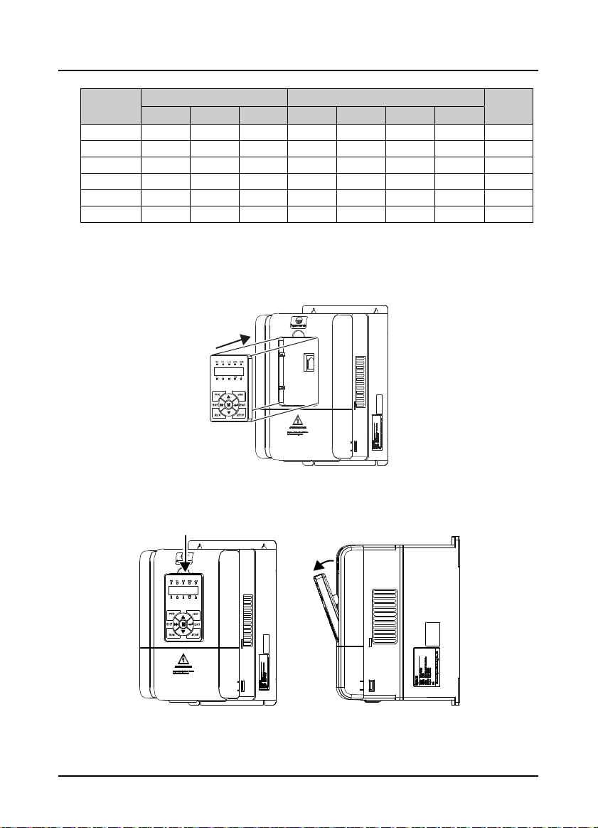
3.5 Install and Dismantle Keypad
According to the direction of Figure 3–1, press the keypad until hear a “click” sound.
Do not install the keypad from other directions or it will cause poor contact.
Figure 3–1 Install keypad
There are two steps in Figure 3–2.
First, press the hook of the keypad according to direction 1. Second, take out of the keypad according
to direction 2.
1
2
Figure 3–2 Dismantle keypad
―12― HD31 Series User Manual V1.1
Shenzhen Hpmont Technology Co., Ltd. Chapter 3 Machenical Installation
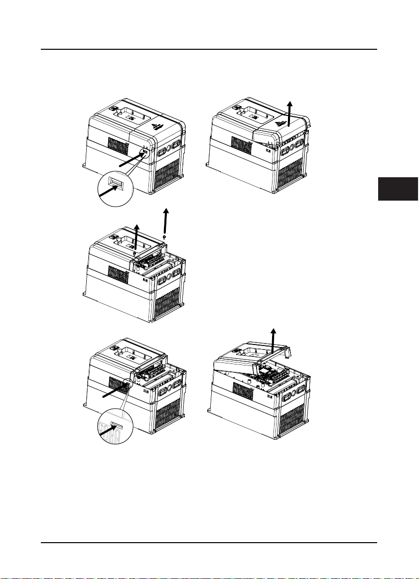
3.6 Dismantle Plastic Cover
The upper cover and lower cover of HD31 are removable. The dismantle steps are shown as Figure 3–3.
Before removing the upper cover, please take away the keypad.
(a)
3
The removing processes of plastic
cover board:
1. Extrude the hooks at both sides together,
take off the lower cover, as (a).
2. Dismantle the screws of upper cover, as (b).
3. Extrude the hooks at both sides together,
take off the upper cover, as (c).
(b)
(c)
Figure 3–3 Dismantle the plastic cover
HD31 Series User Manual V1.1 ―13―

Shenzhen Hpmont Technology Co., Ltd. Chapter 4 Electrical Installation
W
Chapter 4 Electrical Installation
4.1 Precautions
Danger
arning
• Only qualified electrical engineer can perform wiring job.
• Only when the power supply switch is completely off can you do the wiring job.
• You can’t open the inverter cover to do wiring operation until the power is cut-off 10 minutes later. Do not wire or
detach the inverter internal devices at power-on situation.
• Do not do wiring operation until the internal charge indicator of the inverter is off and the voltage between (+)
and (-) of the main circuit terminals is below 36V.
• Check the wiring carefully before connecting emergency stop or safety circuit.
• The earth terminal PE of the inverters must be reliable earthing. It must use t wo separate earth wire due to the
leakage current from the inverter to ground.
• It must use Type B mode when utilize earth leakage protection devices(ELCB/RCD).
• Do not touch the wire terminals of the inverter when it is live. The main circuit terminals is neither allowed
connecting to the enclosure nor short-circuiting.
• Do not do dielectric strength test on the inverter.
• Do wiring connection of the braking resistor or the braking unit according to the wiring figure.
• Make sure the terminals are fixed tightly.
• Do not connect the AC supply cable to the output terminals U, V, W of the inverter.
• Do not connect the phase-shifting capacitors to the output circuit.
• Be sure the inverter has ceased output before switching motor or change-over switches.
• The inverter DC bus terminals must not be short-circuited.
4
4.2 Peripheral Accessories Selection
4.2.1 Wiring specifications of input and output
The AC supply to HD31 must be installed with suitable protection against overload and short-circuits,
i.e. MCCB (molded case circuit breaker) or equivalent device.
The recommended specification of MCCB, contactor & cables are shown as Table 4-2.
The size of ground wire should accord with the requirement in 4.3.5.4 of IEC61800-5-1, as shown in
Table 4-1.
Table 4-1 Sectional area of ground protective conductor
Sectional area S of phase conductor (power supply
cable) while installing (mm2)
Min. sectional area Sp of relative protective conductor
(ground cable) (mm2)
HD31 Series User Manual V1.1 ―15―
S ≤ 2.5 2.5 < S ≤ 16 16 < S ≤ 35 S > 35
2.5 S 16 S/2
Chapter 4 Electrical Installation Shenzhen Hpmont Technology Co., Ltd.
Table 4-2 HD31 I/O wiring specification
Model
HD31-4T2P2P 16 10 1.5 0.75 2.5 F2
HD31-4T3P7P 16 10 2.5 1.5 2.5 F2
HD31-4T5P5P 25 16 2.5 2.5 2.5 F2
HD31-4T7P5P 32 25 4 4 4 F2
HD31-4T011P 40 32 6 6 6 F3
HD31-4T015P 63 40 10 10 10 F3
HD31-4T018P 63 40 10 10 10 F4
HD31-4T022P 100 63 16 16 16 F4
HD31-4T030P 100 63 25 25 16 F5
HD31-4T037P 125 100 35 35 16 F5
HD31-4T045P 160 100 35 35 16 F6
HD31-4T055P 200 125 35 35 16 F6
HD31-4T075P 200 125 50 50 25 F6
HD31-4T090P 250 160 95 70 50 F7
HD31-4T110P 250 160 120 120 50 F7
HD31-4T132P 350 350 120 120 50 F7
MCCB Contacto r Power Cable Motor Cable Ground Cable Size
(A) (A) (mm2) (mm2) (mm2)
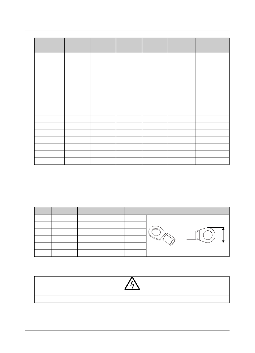
4.2.2 Power terminal lug
Select the lug of power terminal according to the size of terminal, screw size and max. outer diameter
of lug. Refer to Table 4-3.
Take the round terminal as an example.
Table 4-3 Selection of power terminal lug
Size Screw size Tightening torque (N. M) Max. outer diameter of lug d (mm)
F2 M4 1.2 - 1.5 9.9
F3 M5 2.5 - 3.0 12
F4 M5 2.5 - 3.0 12
F5 M6 4.0 - 5.0 15.5
F6 M8 9.0 - 10.0 24
F7 M10 17.6 - 22.5 30
d
4.3 Main Circuit Terminals and Wiring
Danger
• The bare portions of the power cables must be bound with insulation tapes.
―16― HD31 Series User Manual V1.1
Shenzhen Hpmont Technology Co., Ltd. Chapter 4 Electrical Installation
W
arning
• Ensure that AC supply voltage is the same as rated input voltage of HD31.
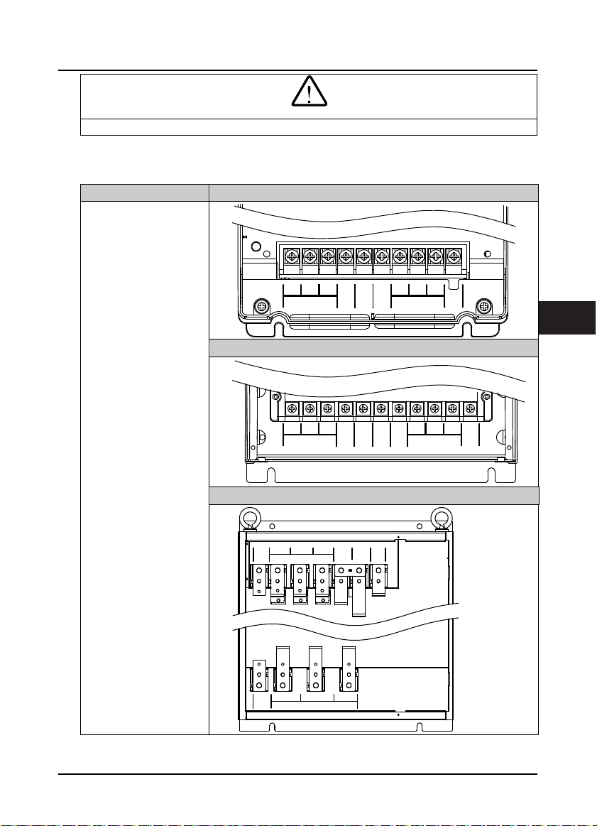
4.3.1 Supply and Motor Terminal
Table 4-4 Supply and motor terminal description
Terminal description Fram e 2
•
L1, L2, L3: Three-phase AC
power input terminals
•
U, V, W: O utput termina ls,
connect to three-phase AC
motor
•
P1, (+):DC reactor
connecti on terminals
•
(+), (-):DC supply input
terminals; DC input
terminals of power
regenerative unit
•
(+), BR: Braking resistor
connecti on terminals
•
PE: Ground terminal,
connect to the ground
Frame 3-Frame 6
Frame 7
L1 L2
PE
PE
L1 L2
L3
L3
MOTOR
(+) (-)
L3
P1
P1
POWER
L1 L2
POWER
POWER
UV
W
(+) (-)
(+) (-)
BR
UV
MOTOR
BR
W
UV
MOTOR
PE
4
W
PE
HD31 Series User Manual V1.1 ―17―

Chapter 4 Electrical Installation Shenzhen Hpmont Technology Co., Ltd.
4.3.2 Supply and Motor Connection
During trial running, make sure HD31 runs forward when the forward command is enabled.
If not, switch any two of the output terminals (U/V/W) or modify parameter F00.17 to change the
motor direction.
The supply and motor connection are shown as Figure 4–1.
Refer to section 4.2 Peripheral Accessories Selection (on page 15) for product options.
Refer to section 9.3 Braking Resistor and Braking (on page 72) for braking resistors and braking units.
Refer to section 9.2 Reactor Selection (on page 71) for AC reactors and DC reactors.
Size F2 connection Size F3 - F6 connection
L1 L2 L3 (+) (-) BR U V W PE
L1 L2 L3 (+) (-) BR U V W PEP1
EMI filter
AC reactor
Mains supply
Braking resistor
MCCB
Contactor Contactor
Supply
ground
L1 L2 L3 (+) (-)PE P1 UV WPE
EMI filter
Supply
ground
AC reactor
Mains supply
DC
reactor
MCCB
Contactor
Figure 4–1 Supply and motor connection
EMI filter
AC reactor
Mains supply
Size F7 connection
Braking
resistor
BR1 BR2(+) (-)
Braking unit
reactor
MCCB
DC
Supply
ground
Braking
resistor
Supply
ground
―18― HD31 Series User Manual V1.1

Shenzhen Hpmont Technology Co., Ltd. Chapter 4 Electrical Installation
W
C
4.4 Control Board and I/O Board
Danger
arning
• The control circuit is basically isolated with the power circuit. Do not touch HD31 after it is powered.
• If the control circuit is connected to the external devices with live touchable port, it should increase an additional
isolating barrier to ensure that classification of external devices not be changed
• If connect the communication terminal of the control circuit to the PC, choose RS485/232 isolating converter
which meets the safety requirement.
• Only connect the relay terminal to AC 220V voltage signal. Other control terminal are strictly forbiden for this
connection.
HD31 includes control board and I/O board, as shown in Figure 4–2.
I/O Board
ontrol Board
4
Figure 4–2 Control board and I/O board
HD31 Series User Manual V1.1 ―19―
Chapter 4 Electrical Installation Shenzhen Hpmont Technology Co., Ltd.
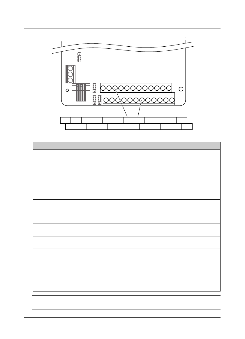
4.4.1 Control Board Terminal
Control Board
Ter min al
+10 A I1 AI2 DI1 DI2 DI3 DI 4 DI5 DI6 COM R1ACOM
GND
Ter mi na l Description
+10, GND
AI1, AI2 Analogue input
AO1, AO2 Analogue output
GND Analogue ground
DI1 - DI6 Digital input
P24, COM
SEL
DO1, CME Digital output
DO2, COM Digital output
R1A/R1B/R1C Relay output
Analogue power
supply
Digital power
supply
Digital input
common terminal
Note:
Limit the current within 3A if the relay terminal is to connect to AC 220V voltage signal.
―20― HD31 Series User Manual V1.1
AO1 AO2
Table 4-5 Control board terminal description
P24 SEL DO1 R1CGND COM CME DO2 R1B
Figure 4–3 Control board term inal
Analogue input use +10V power supply, max. output current is 100mA
GND is isolated to COM
AI1 Input voltage: 0 - 10V (input im pedance: 32kΩ)
AI2 Input voltage: -10 - +10V (input impedance: 32kΩ)
AI2 Input current: 0 - 20mA (input impedance: 500Ω)
• AI2 can be voltage / current selectable
Output voltage / current signal: 0 - 10V/0 - 20mA
Program mable output
Programmable bipolar optional input signal
Input voltage: 0 - 30VDC
DI1 - DI5 input impedance 4.7kΩ, DI6 input i mpedance 1.6kΩ
• DI6 can be selectable for high-frequency input, max-frequency 50kHz
Analogue input use +24V power supply, max. output current is 200mA
COM is isolated to CME
SEL and P24 are connected by default
• Disconnected SEL and P24 when use external power to drive DI
Programmable optical-couple isolation, open collector output
• Output voltage: 0 - 30VDC, max-output current 50mA
• DO2 can be selectable for pulse frequency output, max. frequency 50kHz
CME is isolated to COM, connected to COM by default
• Disconnect CME and COM when they are isolating output
Programmable output, contact rating: 250VAC/3A or 30VDC/1A
• R1B, R1C: normally closed; R1A, R1C: normally open
Shenzhen Hpmont Technology Co., Ltd. Chapter 4 Electrical Installation
C
A
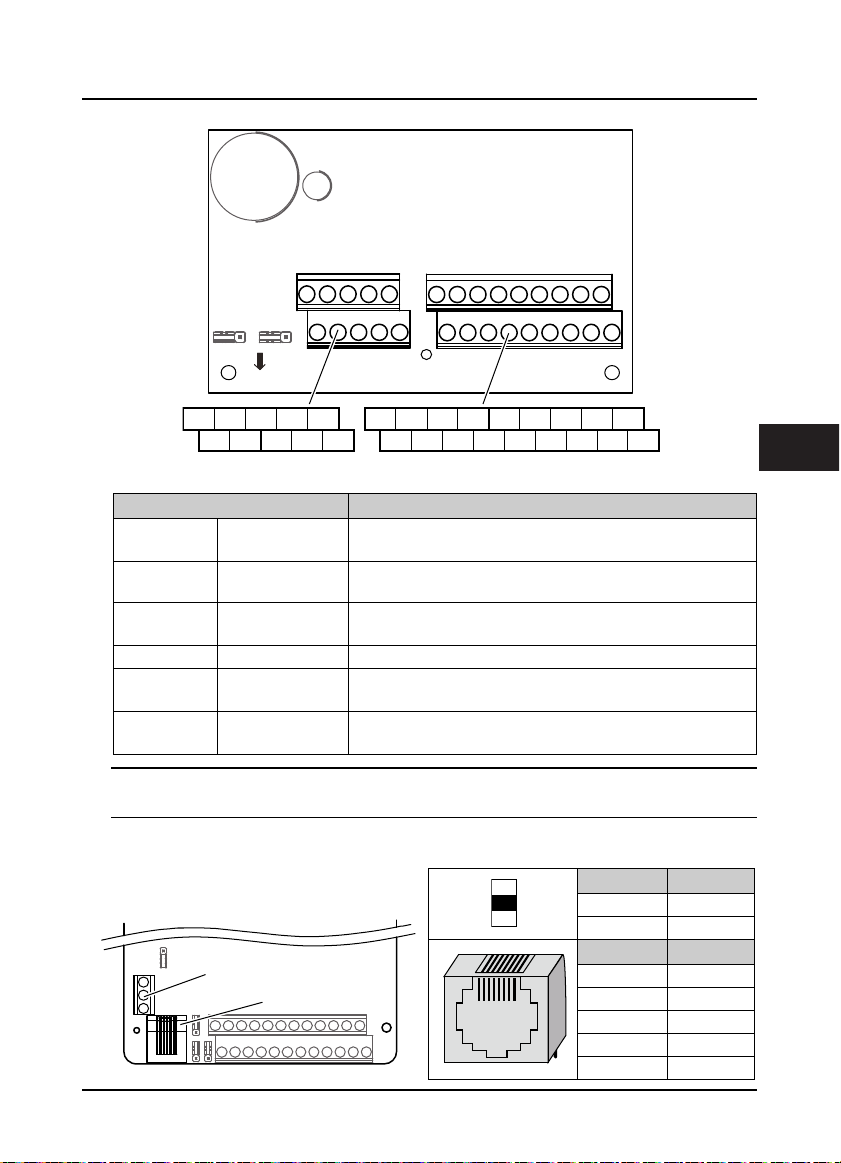
4.4.2 I/O Board Terminal
I/O Board
Ter min alTer min al
R10AR9AR2A R3A R4A R5A R6AR2A R3A R4A R5A R6A R7A R8A
R2A R3A R4A R5A R6A R10
Figure 4–4 I/O board ter minal
Table 4-6 I/O board terminal description
Ter mi na l Funct ion Des cription
AI3 / AI4 Analogue input
+10 / GND
DI7 - DI9 Digital input
P24, COM Digital power supply Digital input use +24V as supply, max. output current is 200mA
SEL
R2A/R2C R10A/R10C
Analogue power
supply
Digital input
common terminal
Relay output
Input voltage: -10 - +10V (input impedance: 32kΩ)
Input current: 0 - 20mA (input impedance: 500Ω)
Analogue input use +10V as supply, max. output current is 100mA
Programmable bipolar optional input, low le vel is effective by default.
Input voltage: 0 - 30VDC (input im pedance: 4.7kΩ)
SEL and P24 are connected by default
• Disconnected SEL and P24 when use external power to drive DI7 - DI9
Programmable normally open output
Contact rating: 250VAC / 3A or 30VDC / 1A
R9CR2C R3C R4C R5C R6C R7C R8C
Note:
Limit the current within 3A if the relay terminal is to connect to AC 220V voltage signal.
4.4.3 Modbus Communication Terminal
Do not use communication terminal and RJ45
simultaneously.
Ter min al
Control Board
RJ45
B
18
RJ45
Ter mi na l Description
A 485+
B 485-
Pin Difinition
1,3 +5V
2 485+
4,5,6 GND
7 485-
8 Unused
4
HD31 Series User Manual V1.1 ―21―

Chapter 4 Electrical Installation Shenzhen Hpmont Technology Co., Ltd.
4.4.4 Jumper
CN9
CN6
CN7
Jumper Description
Control Board
CN8
Figure 4–5 Jumper posi tion
Table 4-7 Jumper description
1
Control
board
CN6
3
AI2 can select voltage or current signal.
• Pin 1 & 2 are short-connected, AI2 inputs voltage signal (factory setting).
• Pin 2 & 3 are short-connected, AI2 inputs cu rrent signal.
1
Control
board
CN7
3
AO1 can select voltage or current signal.
• Pin 1 & 2 are short-connected, AO1 outputs voltage signal (factory setting).
• Pin 2 & 3 are short-connected, AO1 outputs current signal.
1
Control
board
CN8
3
AO2 can select voltage or current signal.
• Pin 1 & 2 are short-connected, AO2 outputs voltage signal (factory setting).
• Pin 2 & 3 are short-connected, AO2 outputs current signal.
1
Control
board
CN9
I/O board
CN2
3
VI
SCI communication can select proper resistance.
• Pin 1 & 2 are short-connected, select the proper resistance.
• Pin 2 & 3 are short-connected, no resistance (factory setting).
31
AI3 can select voltage or current signal.
• Pin 1 & 2 are short-connected, AI3 inputs voltage signal (factory setting).
• Pin 2 & 3 are short-connected, AI3 inputs cu rrent signal.
CN2
I/O Board
CN3
31
AI4 can select voltage or current signal.
• Pin1 & 2 are short-connected, AI4 inputs voltage signal (factory setting).
• Pin2 & 3 are short-connected, AI4 inputs current signal.
I/O board
CN3
VI
―22― HD31 Series User Manual V1.1

Shenzhen Hpmont Technology Co., Ltd. Chapter 5 Keypad
W
Chapter 5 Keypad
Danger
• Only when the terminal cover of HD31 has been fitted can user switch on AC power source. Do not remove the
cover after power is switched on.
• Ensure the motor and the mechnical device are in the use application before HD31 starts.
• Keep away from HD31 if the auto-restart function is enabled at power outage.
• To change the PCBA, correctly set the parameters before running.
• Do not check or detect the signal during HD31 running.
• Do not randomly change HD31 parameter setting.
• Please thoroughly complete all control commissioning and testing, make all adjustments and conduct a full safety
assessment before switching the running command source of HD31.
• Do not touch the energy-depletion braking resistor due to the high temperature.
The standard HD31 are installed with LED keypad which is shown as Table 5-1.
Table 5-1 Key description of keypad
REVFWD ALM LO/RE LOCK
AVRPM%
Hz
Key Description
JOGPRG
ENTSHF
STOPRUN
arning
Entry or exit programming key
In the keypad control, jog start HD31
In the keypad control, press this key to run HD31
a. In the keypad control, press this key to stop HD31
b. In the detection fault, press this key to reset at fault
Set certain function by F00.12
Increase value or parameter
Decrease value or parameter
a. Select display parameter and shift bit
b. Stop in loop/Display the parameter during running
a. Enter lower menu
b. Confirm saving the data
5
HD31 Series User Manual V1.1 ―23―

Chapter 5 Keypad Shenzhen Hpmont Technology Co., Ltd.
The kaypad consists of 5 status indicators and 5 unit indicators and shown as Table 5-2.
Table 5-2 Indicator description of the keypad
Mark Name : Lighting : Flashing : Lightless
Forward status
Reverse status
Alarm status
Remote/Local
status
Password locked
status
Frequency unit
Current unit
Volt age un it
Rotary speed unit
% unit
HD31 is forward running
at the moment
HD31 is reverse running
at the moment
HD31 is faulty at the
moment
Indicate HD31 isn’t in
keypad control mode
The user password lock
of HD31 is avail
The unit of the present
parameter is Hz
The unit of the present
parameter is A
The unit of the current
parameter is V
The unit of the present
parameter is rpm
The unit of the present
function parameter is %
The start of HD31 is forward
running next time
The start of HD31 is reverse
running next time
The present parameter is
output frequency
The present parameter is
rotary speed unit
HD31 is well at the
moment
HD31 is in keypad
control mode
There is no user
password or unlocked
The keypad of HD31 has five LED displays and their meanings are shown in Table 5-3.
Table 5-3 LED display description
LED display Meaning LED display Meaning LED display Meaning LED display Meaning
0 A J U
1 b L u
2 C n y
3 c o -
4 d P Point
5 E q Full display
6 F r No display
7
8 h T
9 i t
H
S
Flash
modifiable
―24― HD31 Series User Manual V1.1

Shenzhen Hpmont Technology Co., Ltd. Chapter 6 Function Introduction
Chapter 6 Function Introduction
This chapter will provide user with detail function introduction of each group.
Display Parameters:
d00: Status Display Parameters, on pages 26 - 29
General Parameters:
F00: Basic Parameters, on pages 29 - 31.
F01: Protection of Parameters, on pages 31 - 32.
F03: Acc / Dec Parameters, on page 33.
F05: External Setting Curve Parameters, on pages 33 -35.
F08: Asynchronous Motor Parameters, on page 35.
F09: V/f Control Parameters, on pages 35 - 36.
F15: Digital I/O Terminal Parameters, on pages 36 - 38.
F16: Analogue I/O Terminal Parameters, on pages 38 - 43.
F17: SCI Communication Parameters, on page 43.
F18: Display Control Parameters, on pages 43 - 44.
F19: Function-boost Parameters, on pages 44 - 45.
F20: Fault Protection Parameters, on pages 45 - 47.
F23: PWM Control Parameters, on page 47.
Specialized parameter for multi-pump water supply:
P00: Water Supply Logic Parameter, on pages 51 - 56.
P01: Water Supply Pump Parameter, on pages 56 - 57.
P02: Water Supply PID Parameter, on pages 57 -59.
P03: Water Supply AIO Function Parameter, on pages 59 - 61.
P04: Water Supply Fault Protection Parameter, on page 61.
P05: Water Supply Time, on page 61.
6
HD31 Series User Manual V1.1 ―25―

Chapter 6 Function Introduction Shenzhen Hpmont Technology Co., Ltd.
6.1 Group d: Display Parameters
Users can directly check the status parameters by checking the function code of Group d.
6.1.1 d00: Status Display Parameters
Ref. Code Function Description Setting Range [Default]
d00.00 Inverter series [Actual value]
d00.01 Software version of the control board [Actual value]
d00.03 Special software version of the control board [Actual value]
d00.05 Software version of the keypad [Actual value]
d00.06 Customized series No. [Actual value]
d00.08 Rated current of the inverter [Actual value]
d00.09 Extended function of the inverter [Actual value]
Display extended function of HD31.
0: No extended function.
1: Constant pressure water supply function.
d00.10 Inverter status [Actual value]
Display HD31 status, as shown in the following table:
Bit13: Current limit
Bit15: Unused Bit14: Unused
Bit10: Speed limit value
Bit11: Unused
Bit7: DC braking
0: Invalid
1: Valid
Bit3: Zero speed
running
0: Invalid
1: Valid
123
d00.14 Setting frequency [Act ual value]
d00.15 Setting frequency (after Acc / Dec) [Actual value]
d00.16 Output frequency [Actual value]
d00.17 Setting RPM [Actual value]
d00.18 Running RPM [Actual value]
d00.19 Three -phase power supply input sequence phase [Actual value]
Display sequence phase of the three-phase input.
• 0: Positive sequence: L1 (R) preceding L2 (S) preceding L3 (T) .
• 1: Negative sequence: L1 (R) preceding L3 (T) preceding L2 (S).
d00.20 Output voltage [Actual value]
d00.21 Output current [Actual value]
d00.23 Output torque [Actual value]
Display output torque which is the relative percentage of the motor rated torque.
d00.24 Output power [Actual value]
Display present actual output power whose unit is 0.1kW.
0: Invalid
1: Valid
Bit6: Unused
Bit2: Forward / reverse
0: Forward
1: Reverse
0: Invalid
1: Valid
Bit9: Unused
Bit5&Bit4: Acc / Dec / Constant
00: Constant
11: Constant
Bit1: Run / stop
0: Stop
1: Run
―26― HD31 Series User Manual V1.1
Bit12: Stall overvoltage
0: Invalid
1: Valid
Bit8: Auto-tuning
0: Not in auto-tuning
1: In auto-tuning
01: Acc
10: Dec
Bit0: Inverter fault
0: No fault
1: Fault

Shenzhen Hpmont Technology Co., Ltd. Chapter 6 Function Introduction
Ref. Code Function Description Setting Range [Default]
d00.25 DC bus voltage [Actual value]
d00.26 Potentiometer input voltage of the keypad [Actual value]
Display potentiometer input voltage of the keypad.
d00.27 AI1 voltage [Actual value]
Display AI1 input voltage.
d00.28 AI1 voltage (after calculating) [Actual value]
Display A1 input voltage which is calculated by the gain, bias and filter.
d00.29 AI2 voltage [Actual value]
Display AI2 input voltage.
When selects current input, 0V corresponds to 0m A and 10.00V corresponds to 20mA.
d00.30 AI2 voltage (after calculating) [Actual value]
Display AI2 input voltage which is calculated by the gain, bias and filter.
d00.31 AI3 voltage [Actual value]
Display AI3 input voltage.
When selects current input, 0V corresponds to 0m A and 10.00V corresponds to 20mA.
d00.32 AI3 voltage (after calculating) [Actual value]
Display AI3 input voltage which is calculated by the gain, bias and filter.
d00.33 AI4 voltage [Actual value]
Display AI4 input voltage.
When selects current input, 0V corresponds to 0m A and 10.00V corresponds to 20mA.
d00.34 AI4 voltage (after calculating) [Actual value]
Display AI4 input voltage which is calculated by the gain, bias and filter.
d00.35 DI6 pulse input frequency [Actual value]
Display DI6 terminal pulse input frequency (Hz).
d00.36 AO1 output [Actual value]
Display AO1 output. When selects current output, 0V corresponds to 0mA and 10.00V corresponds to 20mA.
d00.37 AO2 output [Actual value]
Display AO2 output. When selects current output, 0V corresponds to 0mA and 10.00V corresponds to 20mA.
d00.38 High-speed output pulse frequency [Actual value]
Display high-speed output pulse frequency (Hz).
d00.39 Heatsink temperature [Actual value ]
Display heatsink temperature.
d00.42 Set water supply pressure [Actual value]
When the system is supplying water at constant pressure, the current supply pressure will be displayed.
d00.43 Actual water supply pressure [Actual value]
When the system is supplying water at constant pressure, system pressure value detected by remote
pressure gauge will be displayed.
d00.44 PID setting [Actual value]
Display PID setting relative to full scale (10.00V) percentage.
d00.45 PID feedback [Actual value]
Display PID feedback relative to full scale (10.00V) percentage.
d00.46 PID tolerance [Actual value]
Display PID tolerance relative to full scale (10.00V) percentage.
6
HD31 Series User Manual V1.1 ―27―

Chapter 6 Function Introduction Shenzhen Hpmont Technology Co., Ltd.
Ref. Code Function Description Setting Range [Default]
d00.47 PID integral item [Actual value]
d00.48 PID output [Actual value]
d00.49 External counting value [Actual value]
d00.50 Input terminal status [Actual value]
Display input terminal status. Each bit (binary) of this parameter stands for different physical sources which
d00.51 Output terminal status [Actual value]
Display output terminal status. Each bit (binary) of this parameter stands for different physical sources
d00.55 Total time at power-on [Actual value]
d00.56 Total time at running [Actual value]
d00.55 displays total time at power-on; d00.56 displays total time at running. The unit is hour.
d00.57 High bit of motor total energy consumption [Actual value]
d00.58 Low bit of motor total energy consumption [Actual value]
Display high bit (d00.57) and l ow bit (d00.58) of the motor total energy consumption.
d00.59 High bit of energy consumption at this time running [Actual value]
d00.60 Low bit of energy consumption at this time running [Actual value]
Display high bit (d00.59) and low bit (d00.60) of energy consumption at this time running.
d00.61 Present fault [Actual value]
Display present fault.
Display PID integral item relative to full scale (10.00V) percentage.
Display PID output to full scale ( 10.00V) percentage.
are in the below table.
• 0: Input terminals disconnect with common terminals.
• 1: Input terminals connect with common terminals.
Bit11 Bit10 Bit9 Bit8 Bit7 Bit6 Bit5 Bit4 Bit3 Bit2 Bit1 Bit0
- - - DI9 DI8 DI7 DI6 DI5 DI4 DI3 DI2 DI1
123
which are in the below table.
• 0: Output terminals disconnect with common terminals.
• 1: Output terminals connect with common terminals.
Bit11 Bit10 Bit9 Bit8 Bit7 Bit6 Bit5 Bit4 Bit3 Bit2 Bit1 Bit0
RLY10 RLY9 RLY8 RLY7 RLY6 RLY5 RLY4 RLY3 RLY2 RLY1 DO2 DO1
123
• Displaying 100 means undervoltage.
―28― HD31 Series User Manual V1.1

Shenzhen Hpmont Technology Co., Ltd. Chapter 6 Function Introduction
6.2 Group F: General Parameters
6.2.1 F00: Basic Parameters
Ref. Code Fun ction De scripti on Setting Range [Default]
F00.01 Motor control mode 0 - 2 [0]
0: V/f control. Constant voltage/frequency ratio control.
• It is specially applicable for occasions when one inverter drives more than one motors to achieve
proper efficiency.
• When select V/f control, please properly set the V/f control Group F09 to achieve proper efficiency.
1: Unused.
2: SVC control. Sensorless vector control.
• It is applicable for application with high requirement on inverter performance and torque.
• At first, it must perform motor parameter auto-tuning. And then adjust the settings of F08.00 - F08.04
according to the nameplate of the motor. Start the motor parameter auto-tuning function and
properly set Group F10 parameters, so as to achieve excellent vector control efficiency.
F00.02 Inverter type setting 0,1 [1]
0: G type, to drive heavy and general motor.
F00.04 Extension card selection 0,2 [2]
0: Invalid.
F00.05 HD31 extended function 0,1 [0]
0: No extended.
F00.06 Max. output frequency of HD31 50.00 - 400.00 [50.00Hz]
Defines the max. frequency that HD31 is allowed to output.
F00.07 Upper limit of running frequency setting source 0 - 2 [0]
Defines the highest frequency that user can set, and select setting sources to set the upper limit frequency
F00.08 Upper limit of running frequency 0 - F00.06 [50.00Hz]
F00.07 = 0, the upper limit frequency is set by F00.08.
F00.09 Lower limit of running frequency 0 - F00.08 [0.00Hz]
Use F00.09 to limit the actual output frequency. When the setting frequency value < F00.09, it will operate
1: P type, to drive pump and fan.
2: HD30-WIO extension valid.
1: Constant pressure water supply.
• Be careful to set reasonable parameters accordin g to the nameplate of the motor and the actual running
condition s.
via F00.07.
0: Digital setting. Set the upper limit frequency by F00.08.
1: Analogue input setting. Refer to Group F16.
2: DI6 pulse setting. Set by F16.17, and its max. pulse input frequency corresponds to F00.06 (max. output
frequency of HD31).
at lower limit frequency.
• Properly set the parameters according to the nameplate of the motor and actual running conditions.
• No limitation on the motor parameter auto-tuning function.
• Besides the lower /upper limit frequency, the running frequency of inverter is also limited by the
parameter settings of skip frequency (F05.17 - F05.19).
6
HD31 Series User Manual V1.1 ―29―

Chapter 6 Function Introduction Shenzhen Hpmont Technology Co., Ltd.
Ref. Code Fun ction De scripti on Setting Range [Default]
F00.10 Frequency setting sources 0 - 4 [0]
0: Keypad setting. Change the value by pressing the or key of the keypad.
F00.11 Command setting source 0 - 2 [0]
0: Keypad setting. Start and stop the inveter by pressing , and .
F00.12 M key function 0 - 2 [2]
0: Switch running direction. Switch the keypad running direction by key.
F00.13 Starting frequency digital setting 0 - upper limit [50.00Hz]
F00.10 = 0 or 1, F00.13 sets the initial frequency value.
F00.14 UP / DOWN digital setting 000 - 111 [000]
Only valid when F00.11 = 0 or 1.
Initial value is set by F00.13.
1: Terminal digital setting. Change the value by using the terminals UP / DN, F00.13 sets initial value.
2: SCI communication setting. Change the setting frequency by SCI communication frequency command.
• The initial value of the SCI communication frequency is 0.
3: Analogue setting. Set by the analogue input voltage.
• Refer to Group F16.
• Refer to Group F5 for the corresponding relationship between the analogue value and the running
frequency of HD31.
4: DI6 pulse setting.
• The specification of input pulse signal: voltage range 15 - 30V; frequency range 0 - 50.0kHz.
• Refer to Group F05 for the corresponding relationship between the pulse terminal frequency and the
running frequency of HD31.
1: Terminal setting. Start and stop by using the corresponding external terminals.
• DI terminal is set as FWD (No. 2 function), REV (No. 3 function), refer to Group F15.
2: SCI communication setting. Start and stop by SCI communication port according to communication
protocol.
• F00.11 = 0, it is valid. Do not save when power is off.
1: Switch local and remote control. Switch the local and remote control by key.
• F00.11 = 0 or 1, it is valid.
2: Invalid.
• The current setting frequency value will be replaced by a new one when the value of the F00.13 has been
changed by setting the parameter.
Units: Save selection of frequency setting at power outage
• 0: Do not save at power outage.
• 1: Save to F00.13 at power outage.
Tens: Control selection of frequency setting at stop
• 0: Do not restore to F00.13 at stop.
• 1: Restore to F00.13 at stop.
Hundreds: Save selection of communication setting frequency
• 0: Do not save when power is off.
• 1: Save to F00.13 when power is off.
―30― HD31 Series User Manual V1.1

Shenzhen Hpmont Technology Co., Ltd. Chapter 6 Function Introduction
J
Ref. Code Fun ction De scripti on Setting Range [Default]
F00.15 Jog running frequency digital setting 1 0 - upper limit frequency
F00.16 Interval of jog running 0.0 - 100.0 [0.0s]
After cancel the jog command, HD31 will not
respond to the jog command at the interval of jog
running set by F00.16.
• After the interval of jog is completed, it
immediately executes the arrived jog
command. As show in figure.
F00.17 Running direction 0,1 [0]
0: The same as running command.
1: Opposite to running command.
F00.18 Reverse 0,1 [0]
This function is valid when F00.11 = 0,1,2.
0: Permitted.
1: Prohibitted. It can respond to the FWD / REV commands. When the analogue value is set to positive /
negative voltage and the negative voltage corresponds to the reverse frequency, HD31 will run in
accordance with the zero -frequency run.
F00.19 Dead time of direction switch 0.0 - 3600.0 [0.0s]
Defines the dead time of direction switch, namely, the time of
zero-frequ ency output in th e process of direction switch sho wn as
the right figure.
F00.20 Key enable of optional keypad 0,1 [0]
0: Enabled. When HD31 connects to two keypads, the keys of optional display using the communication
port can be operated.
1: Invalid. When HD31 connects to two keypads, the keys of optional display using the communication port
can not be operated.
F00.21 Dormant function 0,1 [0]
0: Disabled. This function is invalid.
1: Enabled. At running status, when the setting frequency ≤ lower limit of running frequency (F00.09), HD31
coasts to stop and enters dormant status.
F00.22 Dormancy wake up time 0.0 - 360.0 [0.0s]
When HD31 is at dormanc y status, and the setting frequency > lower limit of running frequency (F00.09),
and the duration achieves the setting time of F00.22, then HD31 wakes up from dormancy status, and starts
at the mode of F02.00.
og running
frequency
Jog command
Frequ ency
Acc Dec
Frequ ency
FWD
0
F00.16
F00.19
[5.00Hz]
Time
Time
Time
REV
6
HD31 Series User Manual V1.1 ―31―

Chapter 6 Function Introduction Shenzhen Hpmont Technology Co., Ltd.
H
6.2.2 F01: Protection of Parameters
Ref. Code Fun ction De scripti on Setting Range [Default]
F01.00 User’s password 00000 - 65535 [00000]
XXXXX: To enable the password protection function, set any non-zero numbe r as the password.
• Once the password is set, to change any parameter, input correct password. Otherwise, all the
parameters cannot be changed but only read.
• When input correct password, by pressing key to exit to stop / run display status or by detecting
no press on the keypad within 5 minutes, the user’s password will be valid. To change parameters, input
correct password. It will restart when there is no press on the keypad within 5 minutes.
00000 : The factory setting of F01.00 is 00000, namely the password protection function is disabled.
• If user unlocks the password, it means clearing the user’s password.
F01.01 Menu mode 0,1 [0]
0: Full menu mode. All function parameters can be displayed.
F01.02 Function code parameter initialization (download) 0 - 6 [0]
0: No operation. HD31 is in regular parameter read / write status.
F01.03 Keypad EEPROM parameter initialization (upload) 0 - 2 [0]
0: No operation. HD31 is in regular parameter read / write status.
1: Checking menu mode. Only parameters different from factory setting can be displayed.
• Whether can change the parameter depends on user’s password
status and the actual running condition of HD31.
1: Restore to factory settings.
• Except F01.00, F01.02, F01.03, F19.19, F19.24, F20.08, F20.09, F20.21 -
F20.37, F23.00.
• Steps: If set F01.02 = 1, press to ensure and the parameters are
restored to factory settings. The keypad dispalys “rESEt”. Then the
keypad will display parameters in stop status after finish restoring to
factory setting.
2: Download the keypad EEPROM parameter 1 to the current function code settings.
3: Download the keypad EEPROM parameter 2 to the current function code settings.
4: Clear fault information. The fault history of F20.21 - F20.37 will be clear.
5: Download the keypad EEPROM parameter 1 to the current function code settings (including the motor
parameters).
6: Download the keypad EEPROM parameter 2 to the current function code settings (including the motor
parameters).
1: Upload the current function code settings to the keypad EEPROM
parameter 1.
2: Upload the current function code settings to the keypad EEPROM
parameter 2.
Note: F01.00, F01.02, F01.03, F20.21 - F20.37 and Group y do not upload or
download
Download
Keypad store d
functionparameter
F01.02 = 2 / 3 / 5 / 6
Upload
D31 pr esent s etti ng
function parameter
F01.0 3 = 1 /2
Keypad
HD31
Keypad
HD31
―32― HD31 Series User Manual V1.1

Shenzhen Hpmont Technology Co., Ltd. Chapter 6 Function Introduction
e
6.2.3 F03: Acc / Dec Parameters
Ref. Code Funct ion Des cription Setting Range [Default]
F03.01 Acc time 0.1 - 6000.0
[18.5kW and below: 10.0s]
F03.02 Dec time
Acc time is the time that output frequency accelerates from
0 Hz to F00.06 (the max-output frequency) in linear form.
Dec time is the time that output frequency decelerates from
F00.06 (the max-output frequency) to 0 Hz in linear form.
F03.15 Acc time of jog running 0.1 - 6000.0 [6.0s]
F03.16 Dec time of jog running 0.1 - 6000.0 [6.0s]
F03.15 and F03.16 define the Acc / Dec time of jog running.
F03.17 Dec time of emergency stop 0.1 - 6000.0 [10.0s]
Defines the Dec time of emergency stop.
Frequ ency
F00.06
0
F03.01 F03.02
[22 - 75kW: 30.0s]
[90kW and above: 60.0s]
Tim
6.2.4 F05: External Setting Curve Parameters
Ref. Code Func tion Des criptio n Setting Range [Default]
F05.00 External setting curve 00000 - 22222 [00000]
Units: AI1 curve.
Ten s: A I2 c urv e.
Hundreds: AI3 curve.
Thousands: AI4 curve.
Ten thousands: Pulse input curve.
Each bit setting:
• 0: Line 1.
• 1: Line 2.
• 2: Polyline.
F05.01 Min. setting of line 1 0.0 - F05.03 [0.0%]
F05.02 Min. setting corresponding value of line 1 0.0 - 100.0 [0.0%]
F05.03 Max. setting of line 1 F05.01 - 100.0 [100.0%]
F05.04 Max. setting corresponding value of line 1 0.0 - 100.0 [100.0%]
F05.05 Min. setting of line 2 0.0 - F05.07 [0.0%]
F05.06 Min. setting corresponding value of line 2 0.0 - 100.0 [0.0%]
F05.07 Max. setting of line 2 F05.05 - 100.0 [100.0%]
F05.08 Max. setting corresponding value of line 2 0.0 - 100.0 [100.0%]
F05.09 Max. setting of polyline F05.11 - 100.0 [100.0%]
F05.10 Max. setting corresponding value of polyline 0.0 - 100.0 [100.0%]
F05.11 Inflection point 2 setting of polyline F05.13 - F05.09 [100.0%]
F05.12 Inflection point 2 corresponding value 0.0 - 100.0 [100.0%]
F05.13 Inflection point 1 setting of polyline F05.15 - F05.11 [0.0%]
F05.14 Inflection point 1 corresponding value 0.0—100.0 [0.0%]
F05.15 Min. setting of polyline 0.0 - F05.13 [0.0%]
6
HD31 Series User Manual V1.1 ―33―

Chapter 6 Function Introduction Shenzhen Hpmont Technology Co., Ltd.
Ref. Code Func tion Des criptio n Setting Range [Default]
F05.16 Min. setting corresponding value of polyline 0.0 - 100.0 [0.0%]
F05.01 - F05.04 define line 1. F05.05 - F05.08 define line 2. F05.09 - F05.16 define the polyline.
• Line 1, line 2 and the polyline can independently achieve positive and negative characteristics as shown
in following figure.
• If the curve min. setting is the same as max. setting, it is a line. The default frequency is the corresponding
frequency of the curve min. setting.
Setting
corresponding value
F05.04
F05.08
Positive and negative characteristic of line
Setting
corresponding value
F05.02
F05.06
F05.02
F05.06
F05.01
F05.10
F05.12
F05.14
F05.16
In the figure:
• P / A is terminal pulse / analogue setting.
• Pulse frequency (P) is 100% corresponding to F16.17 max. input pulse frequency.
• Analogue input (A) is 100% corresponding to 10V or 20mA.
F05.17 Skip frequency 1 F00.09 - upper limit [0.00Hz]
F05.18 Skip frequency 2
F05.19 Skip frequency 3
F05.20 Range of skip frequency 0.00 - 30.00 [0.00Hz]
The setting of skip frequency is for output frequency of HD31 to avoid resonance with the load.
• HD31 will skip the above frequencies as shown in
figure. Up to 3 skip frequency ranges can be set.
• During the process of Acc / Dec, HD31 will run with
countinous frequency output, ignoring the skip
frequency ranges. But HD31 will not run at
constant speed in the skip frequency ranges.
• Frequency setting is uncontinuous, while
frequency output is continuous.
F05.05
Setting corresponding value Setting corresponding value
Inflection point 2
Inflection point 1
F05.15
F05.13 F05.11 F05.09 F05.15 F05.13 F05.11 F05.09
P/A(setting) P/A(setting)
F05.03
F05.07
Positive and negative characteristic of polyline
P/A(setting) P/A(setting)
F05.04
F05.08
F05.16
F05.14
F05.12
F05.10
F05.19
F05.18
F05.17
F05.01
F05.05
Setting frequ ency after c alculated
F05.03
F05.07
Inflection point 1
Inflection point 2
Settingfrequency
Skip range
―34― HD31 Series User Manual V1.1

Shenzhen Hpmont Technology Co., Ltd. Chapter 6 Function Introduction
6.2.5 F08: Asynchronous Motor Parameters
R1 R2LI
I1 I2
U1
Io
L
m
LI
1-S
R2
S
R1=F08.07 (Stator resistance)
R2=F08.08 (Rotor resistance)
Io=F08.11 (Excitation current)
LI=F08.09 (Leakage inductance)
Lm=F08.10 (Mutual inductance)
S=Slipratio
The idling excitation current (F08.11) can be calculated by the rated current (F08.02) and power factor
(F08.05) or detected by parameter auto-tuning (F08.06 = 2).
The relationship between rated torque current, F08.11 and F08.02 is below:
Ratedtorquecurrent F08.05F08.02
IdlingexcitationcurrentF08.11 1 F08.052F08.02
MutualinductanceF08.10
Note: Except F08.03, F08.04 and F08.06, the other factory settings are depended on motor.
Ref. Code Func tion Des cription Setting Range [Default]
F08.00 Rated power of motor 0.2 - 500.0kW
F08.01 Rated voltage of motor 0 - 999V
F08.02 Rated current of motor 7.5kW above motor 0.1 - 999.9A
7.5kW and below motor 0.01 - 99.99A
F08.03 Rated frequency of motor 1.0 - 400.0 [50.0Hz]
F08.04 Rated RPM of motor 1 - 24000 [1500rpm]
F08.03 and F08.04 should be set in accordance with the parameters of motor nameplate.
F08.05 Power factor of motor 0.001 - 1.000
F08.06 Parameter auto-tuning of motor 0 - 2 [0]
0: Auto-tuning is disabled.
1: Stationary auto-tuning.
• In the process of stationary auto-tuning, the motor is at rest. The stator resistance, rotor resistance and
leakage inductance will be measured and written into F08.07, F08.08 and F08.09 automatically.
2: Rotary auto-tuning.
• In process of rotary auto-tuning, the motor is at rest at the beginning, and the stator resistance, rotor
resistance and leakage inductance will be measured. Hinterher the motor will start rotating,
accordingly mutual inductance and idling excitation inductance will be measured automatically. All the
measured values above will be saved respectively in F08.07, F08.08, F08.09, F08.10 and F08.11
• When the motor is in rotating status, oscillation, even overcurrent, might occur. In this case, press the
key to stop auto-tuning and then adjust the F09.15 (oscillation-suppression mode) and F09.16
(oscillation-suppression coefficient) suitably to mitigate the possible oscillation.
Note: The auto-tuning is enabled only in keypad control mode (F00.11 = 0).
F08.01
2√3πF08.03F08.11
F08.09
6
HD31 Series User Manual V1.1 ―35―

Chapter 6 Function Introduction Shenzhen Hpmont Technology Co., Ltd.
V
y
V
Ref. Code Func tion De scripti on Setting Range [Default]
F08.07 Stator resistance of motor 7.5kW above motor 0.000 - 9.999Ω
7.5kW and below motor 0.00 - 99.99Ω
F08.08 Rotor resistance of motor 7.5kW above motor 0.000 - 9.999Ω
7.5kW and below motor 0.00 - 99.99Ω
F08.09 Leakage inductance of motor 7.5kW above motor 0.00 - 500.00mH
7.5kW and below motor 0.0 - 5000.0mH
F08.10 Mutual inductance of motor 7.5kW above motor 0.00 - 500.00mH
7.5kW and below motor 0.0 - 5000.0mH
F08.11 Idling excitation current of motor 7.5kW above 0.0 - 999.9A
7.5kW and below 0.00 - 99.99A
Auto-tuning steps:
• 1. Input correct motor parameters as per its nameplate (F08.00 - F08.04).
• 2. When F08.06 is set as 2, set proper Acc time (F03.01) and Dec time (F03.02) and make sure the motor is
disconnected with the load for security.
• 3. Set F08.06 as 1 or 2 firstly, then press the key, and therewith press key to star t auto-tuning.
The LED will display “tunE”.
• 4. When the RUN indicator is flashing, it indicates that auto-tuning has been completed.Now the keypad
displays the parameters of stop status and F08.06 resets to 0.
6.2.6 F09: V/f Control Parameters
Ref. Code Name Description Setting Range [Default]
F09.00 V/f curve of motor 0 - 4 [0]
Defines flexible V/f setting modes so as to meet requirements of different load characteristics.
F09.01 V/f frequency of motor (F3) F09.03 - F08.03 [0.00Hz]
F09.02 V/f voltage of motor (V3) F09.04 - F08.01 [0V]
F09.03 V/f frequency of motor (F2) F09.05 - F09.01 [0.00Hz]
F09.04 V/f voltage of motor (V2) F09.06 - F09.02 [0V]
F09.05 V/f frequency of motor (F1) 0.00 - F09.03 [0.00Hz]
F09.06 V/f voltage of motor (V1) 0 - F09.04 [0V]
F09.01 - F09.06 is user- definable V/f curve.
• Four curves and one user-defined curve can be selected
according to the setting of F09.00.
0: Line. Shown as curve 0 in figure.
1: Square curve. Shown as curve 1 in the figu re.
2: 1.2 exponential curve. Shown as curve 2 in the Figure.
3: 1.7 exponential curve. Shown as curve 3 in the Figure.
4: User-defined curve.
• If F09.00 = 4 (user-definable curve), F09.06 is
enabled.
• The V/f curve can be defined by connecting 3
points of (V1, F1), (V2, F2) and (V3, F3), to
adapt to special load.
• According to the actual condition, set proper
curve to meet the requirements of load
characteristics.
F09.02×F08.01
F09.04×F08.01
F09.06×F08.01
F08.01
0
1/3
×F08. 01
F08.01
oltage
F09.05×
F08.03
0
V2,F2
V1,F1
oltage
1/3
×F08.03
F09.03×
F08.03
V3,F3
F09.01×
F08.03
F08.03
F08.03
0
2
3
1
Frequ enc
Frequ ency
―36― HD31 Series User Manual V1.1

Shenzhen Hpmont Technology Co., Ltd. Chapter 6 Function Introduction
V
V
o
Ref. Code Name Description Setting Range [Default]
F09.07 Torque boost of motor 0.0 - 30.0
F09.08 Cut-off point used for manual torque boost of motor 0.0 - 50.0 (F08.03) [10.0%]
In order to compensate the torque drop at low frequency, HD31 can boost the voltage so as to boost the
F09.09 Slip compensation gain of motor 0.0 - 300.0 [100.0%]
F09.10 Slip compensation filter time of motor 0.01 - 10.00 [0.10s]
F09.11 Slip compensation limit of motor 0.0 - 250.0 [200.0%]
F09.12 Compensation time constant of motor 0.1 - 25.0 [2.0s]
The motor slip changes with the load torque, which results in the variance of motor speed. Reduce the
F09.14 AVR (automatic voltage regulation) function of motor 0 - 2 [1]
0: Disabled.
F09.15 Oscillation-suppression mode of motor 0,1 [0]
0: Depend on excitation current component.
F09.16 Oscillation-suppression coefficient of motor 0 - 200 [50]
This function is used to damp oscillation when output current is continually unstable.
torque.
• No matter what kind of V/f curve is set by
F09.00, the torque boost is enabled.
F09.07 is manually torque boost.
• If F09.07=0, it is manually torque boost. User
needs to set rated frequency (F08.03) and rated
rotary speed (F08.04) of the motor correctly
according to its nameplate.
F09.08 is relative to percentage of rated frequency
(F08.03).
influence through slip compensation (HD31 will automatically adjust its output frequency according to the
load torque).
• In driving status (the actual speed < the setting speed) and in
• The auto slip compensation depends on the rated slip of motor,
• Range of slip compensation = F09.11 × Rated slip.
• Rated slip = F08.03 - F08.04 × Np / 60.
1: Enabled all the time.
2: Disabled in Dec process.
• The output voltage can be regulated to maintain constant via AVR. Thus, normally the AVR function
• In Dec process, if F09.14 = 0 or 2, the running current will be a little higher; while if F09.14 =1, the moto r
1: Depend on torque current component.
• This function helps to keep the motor running smoothly through correctly adjusting the setting of
generating status (the actual speed > the setting speed), the slip
compensation gain (F09.09) should be increased gradually.
consequently make sure the rated frequency (F08.03) and rated
speed (F08.04) are set correctly.
• Np is the number of the motor pole pairs.
should be enabled, especially when the input voltage is higher than the rated voltage.
will decelerate steadily and the current will be smaller.
F09.16.
F08.01
oltage of manual
torque boost
0
[55kW and below: 2.0%]
oltage
Boosted
value
F09.08max
Posit ive sli p
compensation
-100 %
[75 - 132kW: 1.0%]
Frequ ency
F08.03
Slip
Load
100%
Negative slip
c
mpens ation
6
HD31 Series User Manual V1.1 ―37―

Chapter 6 Function Introduction Shenzhen Hpmont Technology Co., Ltd.
6.2.7 F15: Digital I/O Terminal Parameters
Ref. Code Fun ction De scripti on Setting Range [Default]
F15.00 DI1 function 0 – 54 [2]
F15.01 DI2 function 0 - 54 [3]
F15.02 DI3 function 0 - 54 [0]
F15.03 DI4 function 0 - 54 [0]
F15.04 DI5 function 0 - 54 [0]
F15.05 DI6 function 0 - 54 [0]
F15.06 DI7 function 0 - 54 [0]
F15.07 DI8 function 0 - 54 [0]
F15.08 DI9 function 0 - 54 [0]
0: Unused. It disables the terminal function. HD31 ignores the signal input via this terminal.
• The unused terminal is recommended to be set as 0 to avoid wrong connection or action.
1: Inverter enabled.
• When enabled, HD31 is enabled to run;
• When disabled, HD31 is disabled to run and will be in auto stop status.
• If no terminal selects this function, it defaults that HD31 is enabled.
2,3: FWD / REV.
• Set any DI terminal for the FWD / REV to control run / stop of HD31.
• FWD / REV is valid only in terminal control mode (F00.11 = 1).
• Refer to parameter F15.16.
4: Three- wire running mode.
• Refer to parameter 15.16.
12: External stop command input.
• F00.05=1, the pump stops in sequence, otherwise stops according to stop mode. It is valid for all
running command sources.
41,42: Coast to stop normally open / normally closed input.
• HD31 will stop outputting immediately and the load will coast to stop in accordance with the
mechanical inertia when a DI terminal is set as 41 or 42.
44,45: External fault normally open / normally closed input.
• When HD31 receives the EXT signal, E0024 fault (fault of external equipment) will be displayed.
• The fault signal has two input modes: normally open and normally closed input.
46: External reset (RST) input. When HD31 alarms fault, reset it by this terminal.
• The function of RST terminal is the same as the key.
53: Pulse frequency input (DI6).
• This terminal is used to input pulse signal as frequency setting.
• Refer to Group F05 for the relationship between input pulse frequency and frequency setting.
54: Clear fault records. In valid, clear P04.04 at stop.
F15.15 Terminal input positive and negative logic setting 000 - 0x1FF [000]
Defines that each bit (binary) represents different input terminal.
• 0: Positive logic. When input terminals are connected to corresponding common port, this logic is
enabled. Otherwise the logic is disabled.
• 1: Negative logic. When input terminals are connected to corresponding common port, this logic is
disabled. Otherwise the logic is enabled.
Hundreds Ten s Units
Bit11 Bit10 Bit9 Bit8 Bit7 Bit6 Bit5 Bit4 Bit3 Bit2 Bit1 Bit0
- - - DI9 DI8 DI7 DI6 DI5 DI4 DI3 DI2 DI1
―38― HD31 Series User Manual V1.1

Shenzhen Hpmont Technology Co., Ltd. Chapter 6 Function Introduction
)
y
Ref. Code Name Description Setting Range [Default]
F15.16 FWD / REV running mode 0 - 3 [0]
2: Three-wire running mode 1.
F15.18 DO1 function 0 - 35 [2]
F15.19 DO2 function 0 - 38 [0]
F15.20 RLY1 function 0 - 35 [31]
F15.21 RLY2 function 0 - 35 [0]
F15.22 RLY3 function 0 - 35 [0]
F15.23 RLY4 function 0 - 35 [0]
0: Unused.
• FWD:DI terminal is defined as No. 2 function.
• REV: DI terminal is defined as No. 3 function.
• Three-wire running: DI terminal is defined as No. 4 function.
0, 1: Two-wire running mode 1, 2.
• When stop command coming from other so urces makes HD31stop though th e terminal logic enabled
in the terminal control mode, there is no running command even the control terminals FWD / REV are
still valid.
• To run HD31 again, trigger the active FWD and REV.
Run Command
F15.16=1F15.16=0
Stop
00
Reverse
01
Forward
10
Stop
11
Stop
Stop
Forward
Reverse
P24
RUN
FWD /REV
SEL
DIx
DIz
K
DIy
COM
K: Direction se lection terminal (level on
K = 0(for ward) K = 1(reverse)
SB1: Normally cl osed stop button
SB2: Normall
open run button
FWD
REV
P24
SEL
K1
DIx
K2
DIy
K2 K1
COM
• If the shift between SB2 and SB3 is disabled, HD31 will keep the control mode.
3: Three-wire running mode 2.
• If SB2 changes from enabled into disabled, HD31 will keep the same mode.
F15.16=2 F15.16=3
P24
SEL
FWD
SB2 SB2
DIx
Three-wire Three- wire
REV
SB1 SB1
DIz
SB3
DIy
COM
SB1: Normally cl osed stop button
SB2: Normally openforwardbutton
SB3: Normally openreversebutton
1: Inverter is ready.
• HD31 completes power on and no fault occurs, then it can normally run the indicating signal.
2: Inverter running.
• HD31 is in run status and outputs indicating signal.
3: Forward running.
• HD31 is forward running the indicating signal.
4: Reverse running.
• HD31 is reverse running the indicating signal.
6
HD31 Series User Manual V1.1 ―39―

Chapter 6 Function Introduction Shenzhen Hpmont Technology Co., Ltd.
Z
e
e
e
Ref. Code Fun ction De scripti on Setting Range [Default]
6: Zero-freq uency status.
• In the zero-frequency range, the output frequency (including in stop status) outputs the indication
signal.
7: Zero-frequency running.
• In the zero-frequency range HD31 output frequency outputs the indicating signal.
31: Inverter fault.
• HD31 will output fault signal when it has a fault.
32: External fault.
• The indicating signal can output when HD31 detects the external fault signal via terminal.
35: Dormancy indicating function.
38: High-frequency output (DO2).
• DO2 can be selected as high-frequency output.
F15.24 Output terminal logic setting 000 - 0xFFF [000]
Defines that each bit (binary) represents different output terminal.
• 0: Positive logic. When output terminals are connected to corresponding common port, this logic is
enabled. Otherwise the logic is disabled.
• 1: Negative logic. When output terminals are connected to corres ponding common por t, this logic is
disabled. Otherwise the logic is enabled.
Thousands Ten s Units
Bit11 Bit10 Bit9 Bit8 Bit7 Bit6 Bit5 Bit4 Bit3 Bit2 Bit1 Bit0
RLY9 RLY8 RLY7 RLY6 RLY5 RLY4 RLY3 RLY2 RLY1 DO2 DO1
RLY10
123
F15.28 Zero-frequency signal detection threshold 0.00 - upper limit [0.00Hz]
F15.29 Zero-frequency hysteresis
F15.28 and F15.29 are used to set the
zero-frequ ency output contr ol function, refer to
the right figure.
Running frequency
F15.28
Running status
Zero-frequency
running output
ero-freq uency output
F15.29
Tim
Tim
Tim
―40― HD31 Series User Manual V1.1

Shenzhen Hpmont Technology Co., Ltd. Chapter 6 Function Introduction
6.2.8 F16: Analogue I/O Terminal Parameters
Ref. Code Func tion De scripti on Setting Range [Default]
F16.00 Keypad with potentiometer function 0 - 2 [0]
Only when u sing keypad with potentiometer is F16.00 enabled.
F16.01 AI1 function 0 - 2 [2]
F16.02 AI2 function 0 - 2 [0]
F16.03 AI3 function 0 - 2 [0]
F16.04 AI4 function 0 - 2 [0]
0: Unused.
F16.05 AI1 bias -100.0 - 100.0 [0.0%]
F16.08 AI2 bias
F16.11 AI3 bias
F16.14 AI4 bias
F16.06 AI1 gain -10.00 - 10.00 [1.00]
F16.09 AI2 gain
F16.12 AI3 gain
F16.15 AI4 gain
F16.07 AI1 filter time 0.01 - 10.00 [0.05s]
F16.10 AI2 filter time
F16.13 AI3 filter time
F16.16 AI4 filter time
When AI1 - AI4 sets frequency, the relationship between the analogue input and the analogue value after
F16.17 Max. input pulse frequency 0.0 - 50.0 [10.0kHz]
When set the DI6 terminal as pulse input, F16.17 defines the max. input pulse frequency.
F16.18 Input pulse filter time 0 - 500 [10ms]
It is used to filter the input pulse frequency and filter out the small fluctuations in the pulse frequency.
F16.19 AO1 function 0 - 19 [1]
F16.20 AO2 function 0 - 19 [0]
F16.21 High-speed pulse output function 0 - 19 [0]
0: Unused.
1: Upper limit frequency setting
• F00.07 = 1 (analogue input sets upper limit f requency), the upper limit frequency is set by the input
voltage corresponding to the AI terminal.
2: Frequency setting.
• F00.10 = 3 (analogue input sets frequency), the setting frequency is set by the input voltage
corresponding to the AI terminal.
calculating is shown as figure:
Analogue
actu al value
• The formula is: AI actual value = Gain × Value before calculating +Bias
• F16.07, F16.10, F16.13, F16.16 define the filter time.
• The longer filter time is, the higher immunity level is, the response time is prolonged. The shorter filter
time is, the quicker response time is, the lower the immunity level is.
1,2: Output frequency / setting frquency (0 - max. output frequency)
3: Motor RPM (0 - max. output frequency corresponding to RPM).
4: Output current (0 - twice rated current of motor).
Analogue
input filtering
Analogue inputgain
Analogue input bias
Analogue value
after calcu lating
6
HD31 Series User Manual V1.1 ―41―

Chapter 6 Function Introduction Shenzhen Hpmont Technology Co., Ltd.
Ref. Code Func tion De scripti on Setting Range [Default]
5: Output current (0 - twice rated current of motor)
6 - 9: Unused.
10: Output torque (0 - 3 times rated torque of motor).
11: Output voltage (0 - 1.2 times rated voltage of HD31).
12: Bus voltage (0 - 2.2 times rated voltage of HD31).
13: Output power (0 - twice rated power of motor).
14: AI1 input (after calculating).
15: AI2 input (after calculating).
16: AI3 input (after calculating).
17: AI4 input (after calculating).
18,19: Output frequency / setting frequency (- 1 times - 1 times max. output frequency).
F16.22 AO1 bias -100.0 - 100.0 [0.0%]
F16.23 AO1 gain 0.0 - 200.0 [100.0%]
The proportiona l relation of output can be adjusted by output ga in, as shown in the figure below.
• The formula is: AO1 actual output = F16.23 × Value before calculating + F16.22
Valu e af ter
calculating (V)
100%
F16.22=50%
F16.23=50%
50%
010
F16.24 AO2 bias -100.0 - 100.0 [0.0%]
F16.25 AO2 gain 0.0 - 200.0 [100.0%]
Refer to F16.22 and F16.23.
F16.26 DO2 max. output pulse frequency 0.1 - 50.0 [10.0kHz]
Defines the DO2 terminal allowable max. output frequency.
F16.2 2=0
F16.23=100%
Value befor e
calculating (V)
100%
F16.22=0
F16.23=200%
Value aft er
calculating (V)
F16.22 =0
F16.23=100%
Value be fore
calculating (V)
0510
―42― HD31 Series User Manual V1.1

Shenzhen Hpmont Technology Co., Ltd. Chapter 6 Function Introduction
6.2.9 F17: SCI Communication Parameters
Ref. Code Fun ction D escript ion Setting Range [Default]
F17.00 Data format 0 - 5 [0]
0: 1-8-2 fo rmat, no parity, RTU.
1: 1-8-1 format, even parity, RTU.
2: 1-8-1 format, odd parity, RTU.
3: 1-7-2 format, no parity, ASCII.
4: 1-7-1 format, even parity, ASCII.
5: 1-7-1 format, odd parity, ASCII.
F17.01 Baud rate 0 - 5 [3]
0: 1200bps.
1: 2400bps.
2: 4800bps.
3: 9600bps.
4: 19200bps
5: 38400bps.
F17.02 Local address 0 - 247 [2]
F17.02 = 0, it means broadcast address.
F17.03 Host PC response time 0 - 1000 [0ms]
F17.04 Detection time at communication timeout 0.0 - 1000.0 [0.0s]
Time at no communication data > setting time of F17.04, it will be considered as E0028 fault (SCI timeout
fault).
• F17.04 = 0, it will not detect communication timeout.
F17.05 Detection time at communication error 0.0 - 1000.0 [0.0s]
Time at communication error > setting time of F17.05, it will be considered as E0029 fault (SCI error).
• When F17.05 = 0, it will not detect the communication error.
F17.06 Action selection at communication timeout 0 - 3 [3]
F17.07 Action selection at communication error 0 - 3 [3]
F17.08 Action selection at communication peripheral device fault 0 - 3 [1]
F17.06 defines the action selection at commmunication timeout.
F17.07 defines the action selection at communication error.
In the communication command setting mode, F17.08 will define the action selection when
communication peripheral device fault is alarmed.
0: Coast to stop.
1: Emergency stop.
2: Decelerate to stop.
3: Continue to run.
6
HD31 Series User Manual V1.1 ―43―

Chapter 6 Function Introduction Shenzhen Hpmont Technology Co., Ltd.
6.2.10 F18: Display Control Parameters
Ref. Code Func tion Des criptio n Setting Range [Default]
F18.00 Language selection 0,1 [0]
Defines the displaying language on the LCD keypad.
0: Chinese.
1: English.
F18.01 Display contrast of the LCD keypad 1 - 10 [5]
To select LCD display contrast.
F18.02 Set parameter 1 of run status 0 - 49 [8]
F18.03 Set parameter 2 of run status 0 - 49 [7]
F18.04 Set parameter 3 of run status 0 - 49 [36]
F18.05 Set parameter 4 of run status 0 - 49 [13]
F18.06 Set parameter 5 of run status 0 - 49 [14]
F18.07 Set parameter 6 of run status 0 - 49 [18]
F18.08 Set parameter 1 of stop status 0 - 49 [7]
F18.09 Set parameter 2 of stop status 0 - 49 [18]
F18.10 Set parameter 3 of stop status 0 - 49 [20]
F18.11 Set parameter 4 of stop status 0 - 49 [22]
F18.12 Set parameter 5 of stop status 0 - 49 [35]
F18.13 Set parameter 6 of stop status 0 - 49 [36]
The keypad displays parameters which is the run status (F18.02 - F18.07) and stop status (F18.08 - F18.13).
• It can be cycling displayed by key on the keypad.
• Each content of display parameter can be set corresponding to 49 statuses.
• For instance: when set F18.08 as 7, the stop parameter is setting frequency at initial power on.
1: Rated current of HD31.
7: Setting frequency.
8: Setting frequency (after Acc / Dec).
9: Output frequency. At running status,
indicator is flashing.
10: Setting RPM.
11: Running RPM. At running status, indicator
is flashing.
12: Three-phase power supply input phase
sequence.
• 0: Positive sequence, L1(R) preceding L2(S)
preceding L3(T ).
• 1: Negative sequence, L1(R) preceding L3(T)
preceding L2(S)
13: Output voltage.
14: Output current.
16: Output torque.
17: Output power.
18: DC bus voltage.
19: Potentiometer input voltage.
20: AI1 voltage.
21: AI1 voltage (after calculating).
22: AI2 voltage.
23: AI2 voltage (after calculating).
24: AI3 voltage.
25: AI3 voltage (after calculating).
26: AI4 voltage.
27: AI4 voltage (after calculating).
28: DI6 pulse input frequency.
29, 30: AO1 / AO2 output.
31: High-speed output pulse frequency.
32: Heatsink temperature.
35: Content water supply pressure setting.
36: Actula feedback pressure.
37: PID setting.
38: PID feedback.
39: PID error.
40: PID integral value.
41: PID output.
43: Input terminal status.
• Bit0 - Bit8 are corresponding to DI1 - DI9.
44: Output terminal status
• Bit0 - Bit11 are corresponding to DO1, DO2,
RLY1 - RLY10
48: Total time at power on (hour).
49: Total time at running (hour).
―44― HD31 Series User Manual V1.1

Shenzhen Hpmont Technology Co., Ltd. Chapter 6 Function Introduction
6.2.11 F19: Function-boost Parameters
Cooling fan (F19.07 - F19.08)
Ref. Code Name Description Setting Range [Default]
F19.07 Fan control 0 - 2 [0]
F19.08 Fan control delay time 0.0 - 600.0 [30.0s]
Defines the control mode of cooling fan. With overheat protection, the fan runs all the time.
0: Auto stop.
• The fan runs all the time when HD31 is in running status. After HD31stops for the time set by F19.08, the
fan continues running if overheat protection is activated.
1: Immediate stop.
• The fan runs all the time when HD31 is in running status and stops when HD31stops.
2: Runs all the time when power on.
Restart after power failure (F19.16 - F19.17)
Ref. Code Name Description Setting Range [Default]
F19.16 Restart af ter power failure 0,1 [0]
0: Disabled.
F19.17 Delay time for restart after power failure 0.00 - 10.00 [2.00s]
Protection of stall overvoltage (F19.18 - F19.19)
Ref. Code Name Description Setting Range [Default]
F19.18 Stall overvoltage 0,1 [1]
0: Disabled. Braking unit and braking resistor are recommended to be installed if F19.18 is set as 0.
F19.19 Stall overvoltage point 0 - 1200 [740V]
If the stall overvoltage point is set a little lower, Dec time should be comparatively longer.
• The fan runs all the time when HD31 is powered on.
When terminal sets running command, this function decides whether HD31 starts automatically or
not and the delay time for restart when HD31 restarts after power failure.
1: Enabled. In the terminal two-wire control mode and suddenly power failure during running process, when
HD31 is powered on again and the terminal is still enabled, it will wait certain time defined by F19.17 and
then restart with speed tracking mode.
During Dec, the actual decrease rate of motor may < output frequency due to the load inertia. At this
time, the motor will feed the energy back to HD31, resulting in voltage rise on the DC bus. If no
measure is taken, HD31 will trip due to overvoltage.
1: Enabled. During the Dec, HD31 detects the bus voltage and compares it with F19.19.
• If the detected bus voltage > F19.19, HD31 will stop reducing its output frequency. When detect again, if
the DC bus voltage < F19.19, the Dec continues.
Note: Stall overvoltage > 1 minute, HD31 will alarm E0007 fault, meanwhile stops output.
6
HD31 Series User Manual V1.1 ―45―

Chapter 6 Function Introduction Shenzhen Hpmont Technology Co., Ltd.
Auto current limit (F19.20 - F19.22)
Auto current limit is used to limit the load current in real time < F19.21. Therefore HD31 will not trip
due to surge current. It is especially suitable for applications with big load inertia or big change of load.
In auto current limit process, output frequency of HD31 may change; therefore, it is recommended not
to enable when stable output frequency is required.
Ref. Code Name Description Setting Range [Default]
F19.20 Auto current limit 0 - 2 [1]
0: Disabled.
1: Enabled in Acc / Dec running process, but disabled in constant speed running process.
2: Enabled both in Acc / Dec and constant speed running process.
• When the auto current limit is enabled, the output overload capacity will be impaired if auto current limit
threshold is set too low.
F19.21 Auto current limit threshold 20.0 - 200.0 [110%]
Defines the current threshold of auto current limit. The current = F19.21 × rated current of HD31.
F19.22 Dec time at auto current limit 0.0 - 6000.0
Defines the speed rate for the output frequency adjustment at auto current limit action.
• If the setting is too big, it will not be easy to get over the auto current limit status and finally result in
overload fault. If the setting is too small, the frequency will change too sharply and therefore, HD31 may be
in generating status for a long time, which may result in overvoltage protection.
• F19.22=0 , it will not decelerate at current limit.
F19.23 Enabled terminal at power on 0,1 [0]
0: Rise edge.
• For many applications, HD31 is not allowed to auto run to avoid device damage and ensure safety due to
no person interference at power on. In these applications, when the inverter has power initialized and
ready to run, it can not start to run until the terminal run command is given.
1: Level.
• For certain applications, when ensured personal safety and device safety, HD31 needs immediately run at
power on in order to provide automation and efficiency. In these applications, HD31 will immediately run
as soon as the terminal running command is given whether before or after power on.
[18.5kW and below: 10.0s]
[22 - 75kW: 30.0s]
[90kW and above 60.0s]
Braking unit (F19.24)
Ref. Code Name Description Setting Range [Default]
F19.24 Action voltage of braking unit 630 - 750 [720V]
Note: Only in inverter running status is the braking enabled.
―46― HD31 Series User Manual V1.1

Shenzhen Hpmont Technology Co., Ltd. Chapter 6 Function Introduction
6.2.12 F20: Fault Protection Parameters
Overload fault (F20.00 - F20.02)
Ref. Code Name Description Setting Range [Default]
F20.00 Overload pre-alarm detection 00000 - 11111 [00000]
F20.01 Overload pre-alarm detection threshold 20.0 - 200.0 [150.0%]
Defines the current threshold for overload pre-alarm protection. The current = F20.01 × rated current of
F20.02 Overload pre-alarm detection time 0.0 - 60.0 [5.0s]
Defines the time during which the output current of HD31 > F20.01. If the status remains after overload
Units: Overload pre-alarm detection
• 0: It is active all the time in running status.
• 1: It is active only at constant speed.
Tens: Overload pre-alarm action
• 0: HD31 doesn’t alarm and continues running when detecting an active overload signal.
• 1: HD31 alarms and stops running when detecting an active overload signal.
Hundreds: Overload detection threshold
• 0: Relates to rated current of motor (alar m E0019: motor overload).
• 1: Relates to rated current of HD31 (alarm E0017: inverter overload).
Thousands: Motor type
• 0: Standard motor.
• As the cooling effect of the standard motor dete riorates at low speed, HD31 will automatically make
regulation to the time of motor overload protection.
• 1: Variable frequency motor.
• The cooling effect of the variable frequency motor is not affected by the motor speed due to its forced
cooling potential, HD31 will not automatically make regulation to the time of motor overload
protection.
Ten thousands: Overload protection
• 0: Enabled.
• 1: Disabled.
motor / rated current of HD31.
pre-alarm detection time (F20.02), HD31 will alarm E0017 fault (inverter overload) or E0019 fault (motor
overload).
Output load-loss detection fault of HD31(F20.03 - F20.05)
Ref. Code Name Description Setting Range [Default]
F20.03 Output load-loss detection of HD31 0 - 4 [0]
0: Disabled. It does not detect output load-loss.
F20.04 Output load-loss detection threshold of HD31 0 - 100 [30%]
Defines the current threshold of load-loss. The current = F20.01 × rated current of HD31.
F20.05 Output load-loss detection time of HD31 0.00 - 20.00 [1.00s]
If the output current of HD31 < F20.04 and exceeds the time defined by load-loss detection time (F20.05),
1: It detect all the time in running process, and then continues running after detecting (alarm).
2: It detects only at constant speed, and then continues running after detecting (alarm) .
3: It detects all the time in running process, and then cuts off the output after detecting (fault).
4: It detects only at constant speed, and then cuts off the output after detecting (fault).
HD31 will alarm E0018 fault (inverter output load-loss).
• F20.04 or F20.05 = 0, HD31 will not detect load-loss fault.
HD31 Series User Manual V1.1 ―47―
6

Chapter 6 Function Introduction Shenzhen Hpmont Technology Co., Ltd.
Motor overheat fault (F20.06 - F20.07)
It can connect the electronic thermistor embedded motor stator coils to the AI terminal of HD31 in
order to protect motor overheat.
Ref. Code Name Description Setting Range [Default]
F20.06 Motor overheat signal input type 0 - 2 [0]
0: Does not detect the motor overheat.
1: Positive charateristic (PTC).
2: Negative charateristic (NTC).
F20.07 Thermistor value at motor overheat 0 - 10.0 [5.0kΩ]
Input and output voltage phase loss fault (F20.08 - F20.11)
Ref. Code Name Description Setting Range [Default]
F20.08 Input voltage phase loss detection setting 0 - 50 [30%]
F20.09 Input voltage phase loss detection time 1.00 - 5.00 [1.00s]
The detection voltage = F20.08 × rated voltage of HD31.
When HD31 detects certain input voltage < the detection setting (F20.08) and exceeds the detection time
(F20.09), HD31 will alarm E0015 fault (input voltage phase loss).
• F20.08 = 0, HD31 will not detect input voltage phase loss fault.
F20.10 Output voltage phase loss detection setting 0 - 50 [20%]
F20.11 Output voltage phase loss detection time 0.00 - 20.00 [3.00s]
The detection current = F20.10 × rated current of HD31.
When HD31 detects certain output current < the detection setting (F20.10) and exceeds the detection time
(F20.11), HD31will alarm E0016 fault (output voltage phase loss).
• F20.10 or F20.11 = 0, HD31 will not detect output voltage phase loss fault.
PID setting and feedback loss fault (F20.12 - F20.17)
Ref. Code Name Description Setting Range [Default]
F20.12 PID setting lose detection value 0 - 100 [0%]
F20.13 PID setting loss detection time 0.0 - 10.0 [0.20s]
F20.12 value is a percentage of the max. setting source.
F20.14 PID feedback loss detection value 0 - 100 [0%]
F20.15 PID feedback loss detection time 0.0 - 10.0 [0.20s]
F20.14 value is a percentage of the max. feedback s ource.
If the PID setting < F20.12 in the detection time (F20.13), HD31 will alarm E0025 fault (PID setting loss).
• F20.12 or F20.13 =0, HD31 will not detect PI D setting loss fault.
If the PID feedback value < F20.14 in the detection time (F20.15), HD31 will alarm E0026 fault (PID feedback
loss).
• F20.14 or F20.15 = 0, HD31 will not detect PID feedback loss fault.
―48― HD31 Series User Manual V1.1

Shenzhen Hpmont Technology Co., Ltd. Chapter 6 Function Introduction
Fault at PID feedback value out of the limit (F20.16 - F20.17)
Ref. Code Name Description Setting Range [Default]
F20.16 Detection value at PID feedback out of the limit 0 - 100 [100%]
F20.17 Detection time at PID feedback out of the limit 0.00 - 10.00 [0.20s]
F20.16 value is a percentage of the max. feedback s ource.
If the PID feedback value > F20.16 in the detection time (F20.17), HD31 will alarm E0027 fault (PID feedback
out of limit).
• F20.16=100 or F20.17=0, HD31 will not detect PID feedback out of limit fault.
Fault auto reset function and faulted relay action (F20.18 - F20.20)
Auto reset function enables HD31 to reset the fault as per the reset times and interval.
During the reset interval, HD31 stops output and it will automatically restarts with speed tracking
mode.
The following faults do not have the auto reset function:
E0008: Power module fault E0021: Read / Write fault of control board EEPROM
E0010: Braking unit fault E0023: Parameter setting fault
E0013: Soft start contactor failed E0024: Peripheral device fault
E0014: Current detection fault
Ref. Code Name Description Setting Range [Default]
F20.18 Auto reset times 0 - 100 [0]
F20.19 Auto reset interval 2.0 - 20.0 [5.0s/times]
F20.18 = 0, it means “auto reset” is disabled and the fault protection will be activated.
• If no other fault is detected within 5 minutes, the auto reset times will be automatically cleared.
• On condition of external fault reset, auto reset time will be cleared.
F20.20 Faulty relay action 00 - 11 [00]
Units: In auto reset process
0: Faulty relay doesn’t act.
1: Faulty relay acts.
Tens: In the undervoltage process
0: Faulty relay doesn’t act.
1: Faulty relay acts.
Note: Relay needs to be set as No. 31 function (inverter fault).
6
HD31 Series User Manual V1.1 ―49―

Chapter 6 Function Introduction Shenzhen Hpmont Technology Co., Ltd.
Fault history (F20.21 - F20.37)
Ref. Code Name Description Setting Range [Default]
F20.21 Type of fifth latest (the last) fa ult [Actual value]
F20.22 Setting frequency at the last fault
F20.23 Running frequency at the last fault
F20.24 Bus voltage at the last fault
F20.25 Output voltage at the last fault
F20.26 Output current at the last fault
F20.27 Input terminal stat us at the last fault
F20.28 Output terminal status at the last fault
F20.29 Interval at the latest fault
F20.30 Type of fourth latest fault
F20.31 Interval of fourth latest fault
F20.32 Type of third latest fault
F20.33 Interval of third latest fault
F20.34 Type of second latest fault
F20.35 Interval of second latest fault
F20.36 Type of first latest fault
F20.37 Interval of first latest fault
F20.22 - F20.29 record status parameters of HD31 at the last fault.
F20.30 - F20.37 record the type and interval per time of four faults before the latest. The unit of interval is 0.1
hour.
6.2.13 F23: PWM Control Parameters
Ref. Code Name Description Setting Range [Default]
F23.00 Carrier frequency 1 - 16kHz [Depend on HD31]
F23.00 defines the carrier frequency of PWM output wave.
Inverter power Setting range Fa ctor y set ting
7.5 - 30kW 1 - 16k Hz 8kHz
37 - 45kW 1 - 12kHz 6kHz
55kW 1 - 6kHz 4kHz
≥
75kW 1 - 4kHz 2kHz
• The carrier frequency will affect the running noise of the motor. The higher the carrier frequency, the
lower the noise made by the motor. So properly set the carrier frequency.
• When the value > the factory setting, HD31 should be derated by 5% when per 1kHz is increased
compared to the factory setting.
F23.02 PWM overshoot enable 0,1 [1]
0: Disabled.
1: Enabled.
―50― HD31 Series User Manual V1.1

Shenzhen Hpmont Technology Co., Ltd. Chapter 6 Function Introduction
6.3 Group P: Special Parameter for Multi-pump Water Supply
6.3.1 P00: Water Supply Logic Parameter
Ref. Code Name Description Setting Range [Default]
P00.00 Water supply mode 0,1 [1]
0: Running.
• Applicable to common water supply system, e.g., water supply for daily use, industrial use, municipal
use as well as sewage treatment system.
• Also applicable to similar systems, such as oil supply system, vent system and other systems.
1: Commissioning.
• Used for on-site commissioning, and to confirm the switching logic and wiring of HD31.
Note: The above modes are valid when F00.05 = 1. The I/O terminals of I/O board are valid when F00.04=2.
P00.01 Water level (WL) signal input 0 - 2 [0]
0: No input. No control for WL signal of the intake pool.
1: DI terminal input.
• No. 15 - 17 function of P03.04 - P03.12 respectively set the current upper limit WL, lower limit WL and
water shortage WL.
2: AI terminal input.
• The P03.00 - P03.03 set the signal source of the analogue WL.
• The P00.02 - P00.04 respectively set the upper limit WL, lower limit WL and water shortage WL.
P00.02 Upper limit WL of intake pool 0.0 - 100.0 [50.0%]
P00.03 Lower limit WL of intake pool 0.0 - P00.02 [30.0%]
P00.04 Water shortage WL of intake pool 0.0 - P00.03 [10.0%]
P00.05 Backup pressure 0.0 - P05.03×10 [0.0 kg/cm2]
100.0% of the WL signal corresponds to 10V or 20mA.
Water level control:
• When WL of the intake pool decreases:
• The system runs in accordance with P00.05 when water shortage WL of intake pool < current WL <
lower limit WL of intake pool;
• The system stops all of the bumps when current WL < water shortage WL of intake pool.
• When WL of the intake pool increases:
• The system runs in accordance with P00.05 when lower limit WL of intake pool < current WL < upper
limit WL of intake pool;
• The system resumes normal pressure running when upper limit WL of intake pool < current WL.
6
HD31 Series User Manual V1.1 ―51―

Chapter 6 Function Introduction Shenzhen Hpmont Technology Co., Ltd.
Ref. Code Func tion De scripti on Setting Range [Default]
P00.06 Pressure tolerance for adding pump 0.0 - 50.0 [10.0%]
P00.07 Detection time for adding pump 0.0 - 3600.0 [5.0s]
P00.08 Upper switch frequency when adding variable frequency pump P02.27 - upper limit
P00.09 Dec time of variable frequency pump when adding power frequency
pump
P00.10 Pressure tolerance for reducing pump 0.0 - 50.0 [10.0%]
P00.11 Detection time for reducing pump 0.0 - 3600.0 [5.0s]
P00.12 Acc time of variable frequency pump when reducing pump 0.0 - 100.0 [10.0s]
Conditions for adding pump:
1 The currently running frequency reaches P02.27 (upper limit of pressure closed-loop)
•
○
2 Pipe system pressure ≤ setting pressure × (1 - P00.09)
•
○
3 Duration of condition ○1 and ○2 ≥ P00.07
•
○
• Adding variable frequency pump: when the system meets the conditions of adding pump and if next
pump is an inverter drive one.
• The currently running variable frequency pump needs switching to run with power frequency. A
disconnected inverter must comply with P00.13. HD31 needs to accelerate to P00.08, thus to reduce
the network pipe pressure drop and then stops output.
• Disconnect inverter drive contactor, apply P00.13, and connect the normal drive contactor to complete
the frequency change. At the same time, HD31 controls the next pump to proceed to PI
commissioning.
• Adding power frequency pump: when the system meets the conditions of adding pump and if next
pump is a normal drive one.
• The system automatically starts the next power frequency pump.
• To avoid a sudden increase in the pipe pressure, the current variable frequency pump decreases its
output frequency to F00.09 according to P00.09, and proceeds to PI conmissioning.
Note:
1. Priority of adding pumps: variable frequency pump > power frequency pump.
2. If there are multiple normal / inverter frequency pumps, the system adds pumps in a circle way according to
"first stop, first resume".
Conditions for reducing pump:
1 When the current variable frequency pump operates at the lower limit
•
○
•
2 Pipe system pressure ≥ setting pressure × (1 + P00.10)
○
3 Duration of ○1 and ○2 ≥ P00.11
•
○
• Reducing variable frequency pump: when the system meets the conditions of reducing pump and if the
pump is an inverter drive one.
• If the current pump is running with power frequency, directly switch the signal; meanwhile, the pump
accelerates to the upper limit according to P00.12, then proceed to PI commissioning;
• If the current pump is running with variable frequency, there is no need to reduce the pump. The pump
can always run at lower limit frequency.
• Reducing power frequency pump: when the system meets the conditions of reducing pump and if the
pump is a normal drive one.
• Firstly the system disconnects the power frequency signal.
• At the same time, the pump accelerates to upper limit frequency according to P00.12, then proceed to
PI commissioning.
Note: Reduce the power frequency pump preferentially when there are both inverter & power frequency pumps
which run with power frequency.
[50.00Hz]
0.0 - 100.0 [10.0s]
―52― HD31 Series User Manual V1.1

Shenzhen Hpmont Technology Co., Ltd. Chapter 6 Function Introduction
Ref. Code Name Description Setting Range [Default]
P00.13 Breaking delay of pump 1 contacotr 0.000 - 5.000 [0.020s]
P00.14 Touching delay of pump 1 contactor 0.000 - 5.000 [0.200s]
P00.15 Switch circle of power frequency pump 0 - 9999 [0h]
P00.16 Switch circle of variable frequency pump 0 - 9999 [0h]
Switch between power frequency pumps: When there are one power frequency pump in running status
P00.17 Dormancy enable 0 - 4 [0]
0: No dormancy.
P00.18 Pressure tolerance of dormancy awakening 0.0 - 100.0 [10.0%]
P00.19 Delay time of dormancy awakening 0.0 - 3600.0 [5.0s]
Used during the pump switch process. It is used for the mechanical delay close and open of the contactor.
And more importantly, it's used to avoid the remanence effect. This effect occurs during the process of
variable frequency switching to power frequency. Remanence effect may cause the switch fail.
• P00.13 is the duration of HD31 from sending a command of free stop (send an instruction to disconnect
HD31 drive contactor simultaneously) to close the normal drive contactor.
• For pumps over 45kW which require to switch from variable frequency to power frequency, P00.13 can
effectively reduce the switching current and improve successful switching.
• P00.14 is the duration from sending a close command of inverter drive contactor to the output moment
of HD31. It allows for the mechenical delay of the contactor before starting the next variable frequency
pump.
and one that is waiting, the switch will occur only when the running pump meets P00.15.
Switch between variable frequency pumps: When there are one variable frequency pump in running status
and one that is waiting, the switch will occur only when the running pump meets P00.16.
• P00.15 and P00.16 = 0, the switch function is valid.
1: Constant pressure dormancy.
2: Specified pressure dormancy.
3: No flow dormancy1.
4: No flow dormancy 2.
Note: F00.21 and F00.22 support specified pressure dormancy (it's dormant when the setting frequency meets
lower limit frequency).
P00.17 = 0: dormant function is invalid.
• P00.17 = 1: when the system meets the condition of reducing pump, provided that there is no power
frequency pump or variable frequency pump that runs with power frequency, the system enters dormant
status. Mmeanwhile, is will start a dormant pump if there is one in the system.
• P00.17 = 2: when feedback pressure > setting pressure + setting pressure × P00.20, and surpass setting
time of P00.22, the system stops all running pumps and enters dormant status.
• P00.17 = 3: when only one inverter existed in the system, feedback pressure > setting prsssure + setting
pressure × P00.20 and output frequency is smaller than P00.23 for certain time, (if it is starting procedure,
the time will be P00.24, others will be P00.22. if no special requirements, can set P00.22 = P00.24), system
will sleep.
• P00.17 = 4: when only one inverter existed in the system, feedback pressure > setting prsssure + setting
pressure × P00.20 and output frequency is smaller than no-flow power or output frequency is smaller
than P00.23 for a certain time (P00.22), system will sleep.
In dormant status, when feedback pressure < setting pressure - setting pressure × P00.18, and exceeds
setting time of P00.19, the dormancy is awakened. While if P00.17 = 1 , the dormant pump is disconnected.
When dormant is awakened, HD31 drive pump is preferably added if there is any waited in the system. If
there is power frequency pump waiting, it is added directly.
6
HD31 Series User Manual V1.1 ―53―

Chapter 6 Function Introduction Shenzhen Hpmont Technology Co., Ltd.
Ref. Code Name Description Setting Range [Default]
P00.20 Shutdown detection coefficient 0.0 - 100.0 [0.0%]
P00.21 Interval of shutdown the pump and water supply 0.0 - 60.0 [10.0s]
When the system receives stop command, it will shut off the pumps in accordance with P00.21. The shutoff
sequence is: dormant pump > sewage pump > power frequency pump > variable frequency pump running
with power frequency > variable frequency pump running with variable frequency.
P00.22 Detection time of shutdown detection 0.0 - 3600.0 [6.0s]
P00.23 No-flow detecting frequency 0.0 - 50.00[25.00Hz]
P00.24 Detecting time for no-flow detecting start delay 0.0 - 3600.0[60.0s]
P00.25 No flow correction factor 1 - 400[100%]
P00.26 No-flow low speed 0.00 - 99.99 [0.00Hz]
P00.27 No-flow low speed power 0.00 - 10.00 [0.00kW ]
P00.28 No-flow high speed 0.00 - 99.99 [0.00Hz]
P00.29 No-flow high speed power 0.00 - 10.00 [0.00kW]
P00.30 No-flow detection curve 0 - 3 [0]
P00.31 Phase sequence detection enable from variable frequency to power
Before correcting no-flow frequency, pls refer to d00.41.
No-flow power measuring steps:
•
Set F00.05 = 0, F00.10 = 0 and ensure the system reach normal temporature before no-flow power
testing.
•
Close main valve and stop flow
•
When the setted frequency is about 50% of motor rated frequency, recording setted frequency in
P00.26 and recording current value of D00.40 in P00.27
•
When the setted frequency is about 85% of motor rated frequency, recording setted frequency in
P00.28 and recording current value of D00.40 in P00.29.
0: Square curve.
1: Straight line.
2: Cubic curve 1.
3: Cubic curve 2.
Note: By P00.26 - P00.29, corresponding no-flow power will be work out by setted curve and will be recorded in
d00.41, pleasure select reasonbale curve.
0,1 [0]
frequency
0: Disable.
•
No phase sequency detecting before switch variable frequency into power frequency.
1: Enable.
•
Before switch cariable frequency into power frequency, detect phase sequency. And difference of
power frequency phase angle will be changed within range of P00.32 - P00.38.
Note: Detailed steps refer to 7.2 Debugging for Switching between VF and PF, on page 66.
―54― HD31 Series User Manual V1.1

Shenzhen Hpmont Technology Co., Ltd. Chapter 6 Function Introduction
Ref. Code Name Description Setting Range [Default]
P00.32 Switching angle of variable and power frequecny of pump 1 -50.0 - 50.0 [0.0°]
P00.33 Switching angle of variable and power frequecny of pump 2 -50.0 - 50.0 0.0°]
P00.34 Switching angle of variable and power frequecny of pump 3 -50.0 - 50.0 [0.0°]
P00.35 Switching angle of variable and power frequecny of pump 4 -50.0 - 50.0 [0.0°]
P00.36 Switching angle of variable and power frequecny of pump 5 -50.0 - 50.0 [0.0°]
P00.37 Switching angle of variable and power frequecny of pump 6 -50.0 - 50.0 [0.0°]
P00.38 Switching angle of variable and power frequecny of pump 7 -50.0 - 50.0 [0.0°]
P00.39 Dealy of pump 2 contactor breaking 0.000 - 5.000 [0.020s]
P00.40 Dealy of pump 2 contactor touching 0.000 - 5.000 [0.200s]
P00.41 Dealy of pump 3 contactor breaking 0.000 - 5.000 [0.020s]
P00.42 Dealy of pump 3 contactor touching 0.000 - 5.000 [0.200s]
P00.43 Dealy of pump 4 contactor breaking 0.000 - 5.000 [0.020s]
P00.44 Dealy of pump 4 contactor touching 0.000 - 5.000 [0.200s]
P00.45 Dealy of pump 5 contactor breaking 0.000 - 5.000 [0.020s]
P00.46 Dealy of pump 5 contactor touching 0.000 - 5.000 [0.200s]
P00.47 Dealy of pump 6 contactor breaking 0.000 - 5.000 [0.020s]
P00.48 Dealy of pump 6 contactor touching 0.000 - 5.000 [0.200s]
P00.49 Dealy of pump 7 contactor breaking 0.000 - 5.000 [0.020s]
P00.50 Dealy of pump 7 contactor touching 0.000 - 5.000 [0.200s]
When seting as positive angle, variabe frequency phase exceeds power frequency and the difference
reaches setted angle, switching action from variable frequency to power frequcny will be started.
When setting as negative angle, variable frequency is slower than power frequency and the difference
reaches setted angle, switching action from variable frequency to power frequcny will be started.
For details, pleasure see P00.13, P00.14.
6
HD31 Series User Manual V1.1 ―55―

Chapter 6 Function Introduction Shenzhen Hpmont Technology Co., Ltd.
6.3.2 P01: Water Supply Pump Parameter
Ref. Code Name Description Setting Range [Default]
P01.00 Pump 1 type 0 - 4 [0]
P01.01 Pump 2 type 0 - 4 [0]
P01.02 Pump 3 type 0 - 4 [0]
P01.03 Pump 4 type 0 - 4 [0]
P01.04 Pump 5 type 0 - 4 [0]
P01.05 Pump 6 type 0 - 4 [0]
P01.06 Pump 7 type 0 - 4 [0]
0:Invalid. It is not installed or does not work in the system.
1: Variable frequency pump. It starts with variable frequency.
• If it is unqualified to switch, it works as an inverter drive adjustable pump for the whole system. It is
controlled by HD31, which adjust the rotating speed of pump according to the actual pressure so as to
maintain constant system pressure.
• If it is qualified to switch, the pump switches to power frequency running or exit running, depending
on the switch mode.
2: Power frequency pump. It only runs with power frequency.
• Adopt full-pressure direct start method when the power grid is sufficient and the pump power is
under 15kW.
• It is recommended to adopt reduced-voltage method such as reduced-voltage of Y-△mode, self
coupling voltage start, soft start, etc. for pumps with power of no less than 18.5kW. That can reduce
the impact on the power grid and pipe network.
3: Dormant pump. It serves as dormant pump for the system.
• The system enters dormant run when it meets the dormant condition. It will enter dormant running or
awaken dormancy according to the dormant pressure and tolerant limit.
4: Sewage pump. It serves as dormant pump for the system.
• Condition for setting a sewage pump: water level sensor of sewage pool must be installed in the
system and correctly connect to HD31. HD31 automatically controls the start and stop of the sewage
pump according to WL of sewage water pool.
Note:
1. For a pump which is set as variable frequency pump, the corresponding inverter / normal drive relay must be
set again, otherwise it's not recognized as effective pump. After starting the system, HD31 will not output if there
is only one variable frequency pump in the system and no setting for inverter / normal drive relay.
2. For a pump which is set as variable frequency pump, dormant pump and sewage pump, the corresponding
inverter drive relay must be set again, otherwise the is not recognized as effective pump.
P01.07 Rated current of pump 1 7.5kW above motor 0.1 - 999.9A [Depend on motor]
7.5kW and below motor 0.01 - 99.99A [Depend on motor]
P01.08 Rated current of pump2 7.5kW above motor 0.1 - 999.9A [Depend on motor]
7.5kW and below motor 0.01 - 99.99A [Depend on motor]
P01.09 Rated current of pump3 7.5kW above motor 0.1 - 999.9A [Depend on motor]
7.5kW and below motor 0.01 - 99.99A [Depend on motor]
P01.10 Rated current of pump4 7.5kW above motor 0.1 - 999.9A [Depend on motor]
7.5kW and below motor 0.01 - 99.99A [Depend on motor]
P01.11 Rated current of pump5 7.5kW above motor 0.1 - 999.9A [Depend on motor]
7.5kW and below motor 0.01 - 99.99A [Depend on motor]
P01.12 Rated current of pump6 7.5kW above motor 0.1 - 999.9A [Depend on motor]
7.5kW and below motor 0.01 - 99.99A [Depend on motor]
―56― HD31 Series User Manual V1.1

Shenzhen Hpmont Technology Co., Ltd. Chapter 6 Function Introduction
Ref. Code Name Description Setting Range [Default]
P01.13 Rated current of pump7 7.5kW above motor 0.1 - 999.9A [Depend on motor]
7.5kW and below motor 0.01 - 99.99A [Depend on motor]
Please set the above rated current according to the nameplate on the motor. These parameters will affect
the overload protection of HD31 for the motor.
6.3.3 P02: Water Supply PID Parameter
Ref. Code Name Description Setting Range [Default]
P02.00 Pressure setting source 0 - 2 [0]
0: Digital setting. P02.01 sets the setting pressure.
1: Pressure setting of timing water supply. P02.02 - P02.26 set the setting pressure.
2: Pressure setting of analogue water supply. The selected analogue of P03.00 - P03.03 set the setting
pressure.
P02.01 Pressure digital setting 0.0 - P05.03×10 [0.0 kg/cm2]
Used for digital pressure setting. 100.0% of digital setting is corresponding to 10V or 20mA.
Note:
1. 100.0% of the feedback signal is corresponding to 10V or 20mA.
2. 100% of P00.05
P02.26, P04.00 and P04.02 is corresponding to 10V or 20mA.
3. 100% of P00.06, P00.10, P00.18 and P00.20 is corresponding to the setting pressure of P02.00.
P02.02 Pressure time 1 - 12 [1]
P02.00 = 1, multi-time pressure is valid.
P02.03 T1 start time 00.00 - 23.59 [00.00]
P02.05 T2 start time 00.00 - 23.59 [00.00]
P02.07 T3 start time 00.00 - 23.59 [00.00]
P02.09 T4 start time 00.00 - 23.59 [00.00]
P02.11 T5 start time 00.00 - 23.59 [00.00]
P02.13 T6 start time 00.00 - 23.59 [00.00]
P02.15 T7 start time 00.00 - 23.59 [00.00]
P02.17 T8 start time 00.00 - 23.59 [00.00]
P02.19 T9 start time 00.00 - 23.59 [00.00]
P02.21 T10 start time 00.00 - 23.59 [00.00]
P02.23 T11 start time 00.00 - 23.59 [00.00]
P02.25 T12 start time 00.00 - 23.59 [00.00]
P02.04 T1 time pressure 0.0 - P05.03×10 [0.0 kg/cm2]
P02.06 T2 time pressure 0.0 - P05.03×10 [0.0 kg/cm2]
P02.08 T3 time pressure 0.0 - P05.03×10 [0.0 kg/cm2]
P02.10 T4 time pressure 0.0 - P05.03×10 [0.0 kg/cm2]
P02.12 T5 time pressure 0.0 - P05.03×10 [0.0 kg/cm2]
P02.14 T6 time pressure 0.0 - P05.03×10 [0.0 kg/cm2]
P02.16 T7 time pressure 0.0 - P05.03×10 [0.0 kg/cm2]
P02.18 T8 time pressure 0.0 - P05.03×10 [0.0 kg/cm2]
P02.20 T9 time pressure 0.0 - P05.03×10 [0.0 kg/cm2]
P02.22 T10 time pressure 0.0 - P05.03×10 [0.0 kg/cm2]
P02.24 T11 time pressure 0.0 - P05.03×10 [0.0 kg/cm2]
P02.01, P02.04, P02.06, P02.08, P02.10, P02.12, P02.14, P02.16, P02.18, P02.20, P02.22, P02.24,
、
HD31 Series User Manual V1.1 ―57―
6

Chapter 6 Function Introduction Shenzhen Hpmont Technology Co., Ltd.
Ref. Code Name Description Setting Range [Default]
P02.26 T12 time pressure 0.0 - P05.03×10 [0.0 kg/cm2]
Used for time setting of multi-time pressure water supply and the pressure setting of the corresponding
P02.27 Upper limit of pressure closed-loop 0 - upper limit [50.00Hz]
Max. frequency of closed-loop regulator output.
P02.28 Proportional gain of pressure closed-loop (Kp) 0.00 - 10.00 [0.01]
Defines the proportional gain, decides the adjustment intensity of the regulator: the bigger KP is, the
P02.29 Integration time of pressure closed-loop (Ti) 0.01 - 10.00 [0.10s]
Defines the integration time (Ti), and decides the speed of integration adjustment. The regulator makes
P02.30 Differential time of pressure closed-loop (Td) 0.00 - 1.00 [0.00s]
Differential time decides the intensity of integration adjustment. The regulator makes adjustment for the
P02.31 Sampling time (T) 0.01 - 30.00 [0.50s]
Defines sampling time of feedback value. The regulator calculates once during every sampling period.
P02.32 Bias limit 0.0 - 20.0 [2.0%]
The output value of the regulator is relevant to the max. tolerance of pressure setting. Within permitted
P02.33 Output wave filter of pressure closed-loop 0.01 - 30.00 [0.50s]
Make wave filter to the output frequency signal of the regulator, and avoid the jumping interfering signal to
P02.34 Regulating characteristic of pressure closed-loop 0,1 [0]
0: Positive characteristic. When the setting is added, pressure increases.
P02.35 Digital setting for saving selection when power failure 0,1 [1]
0: Not saving.
time.
• Principle of time s etting: T1 ≤ T2 ≤ T3 ≤ T4 ≤ T5 ≤ T6 ≤ T7 ≤ T8 ≤ T9 ≤ T10 ≤ T11 ≤ T12.
• T1 refers to the beginning of T1 till beginning of T2; T2 refers to the beginning of T2 till the beginning of
T3, and so forth. T12 refer to the beginning of T12 till the beginning of T1.
• The beginning time of a certain period may be the same as its' previous one. In this case, the previous
one joins to this period.
• There is only one period per day if T1 = T2 = T3 = T4 = T5 = T6 = T7 = T8 = T9 = T10 = T11 = T12.
higher intensity will be.
adjustment for the tolerance of feedback / setting pressure.
• When the tolerance of feedback / setting pressure is 100%, the integral regulator, with the continuous
adjustment of P02.29, reaches the max. pressure (overlook the effect of P02.28 and P02.30).
• The shorter integration time is, the faster adjustment speed will be.
tolerance change of the feedback / setting pressure.
• The adjustment of the derivative adjustment is max. pressure if the feedback pressure changes 100%
within P02.30 (overlook the effect of P02.28 and P02.29).
• The longer integration time is, the higher adjustment intensity will be.
• The longer sampling time is, the slower response will be.
range, the re gulator stops regulating.
influence on the system.
• Adjustment sensitivity is affected by overlong time of wave filtering.
1: Negative characteristic. When the setting is added, pressure decreases.
1: Saving.
When P02.00 = 0 and inverter is in stop/running, setted pressure is displaying. We can adjust the setted
pressure through button or . After power failure, adjusted pressure value can be saved by P02.35.
―58― HD31 Series User Manual V1.1

Shenzhen Hpmont Technology Co., Ltd. Chapter 6 Function Introduction
6.3.4 P03: Water Supply AIO Function Parameter
Ref. Code Name Description Range setting [Default]
P03.00 AI1 function 0 - 3 [0]
P03.01 AI2 function 0 - 3 [0]
P03.02 AI3 function 0 - 3 [0]
P03.03 AI4 function 0 - 3 [0]
0: Unused.
1: Analogue pressure setting.
• When P02.00 = 2 (pressure setting of analogue water supply), this function is selected by analogue
source, which corresponds to input voltage. The input voltage sets the setting pressure.
2: Analogue feedback setting.
• This function is selected by analogue source, which corresponds to input voltage. The input voltage
sets the feedback pressure.
3: Anologue WL feedback
• When P00.01 = 2 (WL signal is set by analogue source), this function is selected by analogue source,
which corresponds to input volta ge. The input voltage decides the WL signal.
Note:
1. Once set P03.00 - P03.01, the corresponding F16.01 - F16.02 are invalid.
2. 0 - 10V of AI1 - AI4 are corresponding to feedback signal 0 - 100.0%.
P03.04 DI1 function 0 - 19 [0]
P03.05 DI2 function 0 - 19 [0]
P03.06 DI3 function 0 - 19 [0]
P03.07 DI4 function 0 - 19 [0]
P03.08 DI5 function 0 - 19 [0]
P03.09 DI6 function 0 - 19 [0]
P03.10 DI7 function 0 - 19 [0]
P03.11 DI8 function 0 - 19 [0]
P03.12 DI9 function 0 - 19 [0]
0: Unused.
1 - 7: pump 1 - 7 commissioning running.
• Respectively specify inverter drive motor that needs commissioning start. When the commission
terminal of the specified variable frequen cy pump is valid, the pump will start with variable frequenc y,
and switch to power frequency after meeting P00.08. If there are multiple valid commission terminals,
HD31 starts and switches them according to their consequence of switch off.
8 - 14: pump 1 - 7 invalid.
• Respectively specify motors that needs to quit the system. When the command is effective, the
corresponding motor will not participate in switch logic of the system. This function enables force quit
if the motor needs inspecting or fault occurs to the motor. That can enhance the switch efficiency.
15: Upper limit water level( WL) of intake pool.
16: Lower limit WL of intake pool.
17: Water shortage WL.
• When P00.01 =1 , No. 15- 17 decide the upper limit WL, lower limit WL and water shortage WL.
18: Upper limit WL of sewage pool.
19: Lower limit WL of sewage pool.
• The sewage pump is triggered into use when WL of sewage pool exceeds upper limit WL; otherwise it
deactivates and stops output.
Note: After setting the P03.04 - P03.09 functions, the corresponding F15.00 - F15.05 function are invalid.
6
HD31 Series User Manual V1.1 ―59―

Chapter 6 Function Introduction Shenzhen Hpmont Technology Co., Ltd.
Ref. Code Name Description Setting Range [Default]
P03.13 DO1 function 0 - 23 [0]
P03.14 DO2 function 0 - 23 [0]
P03.15 RLY1 function 0 - 23 [0]
P03.16 RLY2 function 0 - 23 [0]
P03.17 RLY3 function 0 - 23 [0]
P03.18 RLY4 function 0 - 23 [0]
P03.19 RLY5 function 0 - 23 [0]
P03.20 RLY6 function 0 - 23 [0]
P03.21 RLY7 function 0 - 23 [0]
P03.22 RLY8 function 0 - 23 [0]
P03.23 RLY9 function 0 - 23 [0]
P03.24 RLY10 function 0 - 23 [0]
0: Unused. No output function.
1,3,5,7,9,11,13: pump 1 - 7 variable frequency running.
2,4,6,8,10,12,14: pump 1 - 7 power frequency running.
• Define the control signal of every pump. HD31 drive pump needs both control signals of variable
frequency and industrial signal.
• Please do wiring correctly during commissioning.
• Only power frequency signal is effective for power frequency pump, sewage pump and dormant
pump.
15: Dormant running.
• This signal is valid when the system is in dormant running mode.
16: Over-pressure.
• This signal is valid when the pressure of pipe network is pressure of P04.00 or above, and sustains the
setting time of P04.01.
17: Under- pressure.
• This signal is valid when pipe network pressure is pressure of P04.02 or below, and sustains the setting
time of P04.03.
18: Backup pressure running.
• This signal is valid when the system meets the running condition of backup pressure and runs
according to it.
• Refer to P00.01 - P00.05.
19: Pool water shortage.
• This signal is valid when WL of the intake pool < shortage WL.
20: WL of the sewage pool reaches the upper limit.
• This signal is valid when WL of the sewage pool exceeds the upper limit WL.
21: Faulty pump occurs.
• This signal is valid when P04.04 is not 0.
22: Unused.
23: The supply system is in running status.
• This signal is valid when the water supply system is in running status.
Note: After setting the P03.13 - P03.15 functions, the corresponding functions of F15.18 - F15.20 are invalid.
―60― HD31 Series User Manual V1.1

Shenzhen Hpmont Technology Co., Ltd. Chapter 6 Function Introduction
6.3.5 P04: Water Supply Fault Protection Parameter
Ref. Code Name Description Setting Range [Default]
P04.00 Setting value of over-pressure protection 0.0 - P05.03×10 [0.0 kg/cm2]
P04.01 Detection time of over-pressure protection 0.0 - 3600.0 [300.0s]
The system alarms for over-pressure when the pipe network pressure reaches the max. setting of P04.00
P04.02 Setting value of under-pressure protection 0.0 - P05.03×10 [0.0 kg/cm2]
P04.03 Detection time of under-pressure protection 0.0 - 3600.0 [300.0s]
Alarm on and off for under-pressure protection is similar with over-pressure protection (refer to P04.00 and
P04.04 Record of faulty pump 0 - 0x7F [0]
P04.05 Troubleshooting for the inverter 0,1 [0]
0: The whole system stops.
and sustains the setting time of P04.01.
The alarm will stop only after value of the pipe network pressure is no more than the over-pressure
protection value and sustains the setting time of P04.01.
P04.01).
• When an variable frequency pump occurs fault which can be reset, the system automatically reset the
pump according to F20.18 and F20.19. If the fault can not be reset, the system automatically stops the
pump.
• Reset times for fault > setting value of F20.18 and fault still exits, HD31 records this pump (its bit set as 1)
and marks it as invalid. Meanwhile, the faulty pump quits the system and does not participate in the
switch logic.
• The following figure shows corresponding relationship between the pump and the position.
Bit8 Bit7 Bit6 Bit5 Bit4 Bit3 Bit2 Bit1
Unuse d Pum p 7 Pum p 6 Pum p 5 Pum p 4 Pum p 3 Pump 2 Pump 1
• The faulty pump which had troubleshot can participate the switch logic only after clear fault information
(F01.02 = 4).
Example: P04.04 = 0x18= 00011000B indicates that the pump 4 and pump 5 occurs fault.
• Record the current faulty pump and stop the whole water supply system.
• If the the system had set auto-reset function, it will reset for the corresponding times and carry out the
above operation. Otherwise it will carry out the above operation directly without reset.
1: HD31 automatically switches to the next variable frequency pump; while if there is no such pump, HD31
controls in power frequency mode.
• Record the current faulty pump and quit the water supply system. The system preferentially starts an
inverter drive one if there are variable frequency pump or power frequency pump ready to run.
• If the the system had set auto-reset function, it will reset for the corresponding times and carry out the
above operation. Otherwise it will carry out the above operation directly without reset.
6.3.6 P05: Water Supply Time Parameter
Ref. Code Name Description Setting Range [Default]
P05.00 Set current time ( Year) 11 – 99 [Actual value]
Set time of the system: Year.
P05.01 Set current time (Month & Date) 0101 – 1231 [Actual value]
Set time of the system: Month & Date.
P05.02 Set current time (Hour & Minute) 0000 – 2359 [Actual value]
Set time of the system: Hour & Minute.
6
HD31 Series User Manual V1.1 ―61―

Chapter 6 Function Introduction Shenzhen Hpmont Technology Co., Ltd.
Ref. Code Name Description Setting Range [Default]
P05.03 Pressure sensor range setting 0.0 - 10.0 [1.6MPa]
1MPa=10kg/cm2.
P05.04 Pressure sensor signal type selection 0 - 2 [0]
0: 0 - 10V.
1: 0 - 20mA.
2: 4 - 20mA.
Note:
1. Only the AI2, AI3, AI4 terminals can be input the current signal and need to change the CN6 of the control
board or the CN2 or CN3 jumper on water supply card. Please refer to the jumper description in the user manual
for details.
2. When P05.04 = 2, set the F05.00 teb bit to 1 and set F05.05 = 20.0%. When P05.04 = 0 or 1, set F05.00 ten bit to
0 and set to F05. 05 = 0.0%.
P05.05 Water supply method selection 0x00 - 0x75 [0x00]
Modify P05.05 and system will automatically set P01.00 - P01.06, P03.15 - P03.24. Set the principle:
Follow P01.00 - P01.06 to set the frequency conversion / power frequency pump, set P03.16 - P03.24,
P03.15 power and variable frequency control in turns.
For ex ample
Ref. Code Funct ion Va lue Defination
P01.00 Pum p 1 type 1 Pump 1 is
P01.01 Pum p 2 type 1 Pump 2 is
P01.02 Pum p 3 type 1 Pump 3 is
P01.03 Pum p 4 type 1 Pump 4 is
P01.04 Pum p 5 type 2 Pump 5 is power fre quency pu mp
P01.05 Pum p 6 type 2 Pump 6 is power fre quency pu mp
P01.06 Pum p 7 type 0 Invalid
P03.15 RLY1 function 12 Pump 6 power frequency running
P03.16 RLY2 function 1 Pump 1 variable frequency running
P03.17 RLY3 function 2 Pump 1 power frequency running
P03.18 RLY4 function 3 Pump 2 variable frequency running
P03.19 RLY5 function 4 Pump 2 power frequency running
P03.20 RLY6 function 5 Pump 3 variable frequency running
P03.21 RLY7 function 6 Pump 3 power frequency running
P03.22 RLY8 function 7 Pump 4 variable frequency running
P03.23 RLY9 function 8 Pump 4 power frequency running
P03.24 RLY10 function 10 Pump 5 power frequency running
Note:
1. A bit indicates the number of variable frequency pumps in the system; ten indicates the number of frequency
pumps in the system.
2. The number of frequency pump plus frequency pump can not exceed 7, the total number of relays can not be
more than 10.
: Set P05.05 = 0x24, the parameters automatically set, as follows:
variable frequency
variablefrequency
variable frequency
variablefrequency
pump
pump
pump
pump
―62― HD31 Series User Manual V1.1

Shenzhen Hpmont Technology Co., Ltd. Chapter 7 Application Reference
Chapter 7 Application Reference
7.1 Take One-to-Six Inverter as an Example.
1. Compatible with: variable pump x 2, industrial pumps x 2, dormant pump x 1, sewage pump x 1.
2. Technical requirements:
• The analogue value sets the water pressure.
• The analogue value feeds back the intake pool WL (water level) signal. The liquid level signal feeds
back the sewage pool WL signal.
• Backup pressure function: 0.2Mpa backup pressure.
3. Pressure gauge selection: remote control, DC 0 - 10V output, 1Mpa range.
HD31 system wiring is shown in figure below.
7
HD31 Series User Manual V1.1 ―63―

Chapter 7 Application Reference Shenzhen Hpmont Technology Co., Ltd.
TA6
Sewage pump
KM4
KM2
QA6
KM8
QA5
KM7
QA4
KM6
QA3
KM5
QA2
QA1
K1
KM8
FR6
TA5
K1
KM7
FR5
TA4
K1
KM6
FR4
TA3
K1
TA2
K1
K3
K2
KM4
TA1
K1
K3
KM2
FR2 FR3
KM3 KM4 KM5
K2
FR1
KM1 KM2
Q3
KM1
Q2
3~
M1
V
U
L1L2L3
3~
M2
pump
Variable frequency
Q4
FR1
KM2
K1
S1
Run / Stop
W
P24
DI1 - DI3
KM3
COM
10V
pump
Variable frequency
FR2
KM4
Pressure
setting
AI1
GND
HD31
PE
DI4
DI5
DI8
DI9
DI6
DI7
S3K1S2
S5
S4
Pump 1 CR
Pump 2 CR
Q1
Lower limit WL of SP
Upper li mit WL of SP
Q01
KM1
KM2
KM3
KM4
Pressure
PT
AI2
COM
KM5
3~
M3
Q5
FR3
KM5
feedback
GND
R9A
R2A
GND
AI3
WL det ecti on of I S
KM6
3~
M4
Q6
Power frequency pump
FR4
KM6
R9C
R8C
R8A
R7A
R2C
R3A
R3C
R4A
SB1
KM7
KM8
3~
M5
Q7
Power frequency pump
FR5
KM7
R7C
R6C
R6A
R4C
R5A
R6C
Manual
Auto
M
K1
Dormant pump
R1C
R1A
P24
DO1
CME
COM
KM1
K2
3~
M6
Q8
FR6
KM8
K4
K1
KM3
K4
K3
N
L1
L2
L3
Pump 1 PFrun
Pump 2 PFrun
Pump 3 PFrun
Pump 1 VF run
Pump 2 VF run
Pump 4 PFrun
Sewage pump run
Dormant pump run
One-to-six wiring
Auto run
Manual run
Interver fault
VF = variable frequency
PF = power frequ ency
CR = Commissioning running
SP = Sewage pool
IS = Intake sump
Fault pump occurs
WL = Water l evel
―64― HD31 Series User Manual V1.1

Shenzhen Hpmont Technology Co., Ltd. Chapter 7 Application Reference
Set parameter
Ref. Code Setting Description
F00.04 2 I/O terminal signal on HD31-WIO board is enabled
F00.05 1 Water supply function is enabled
F00.11 1 Terminal sets setting source
F15.00 2 Input terminal DI1: set as FWD command
P00.00 0 or 1
P01.00 1
P01.01 1
P01.02 2
P01.03 2
P01.04 3 Pump 5: dormant pump
P01.05 4 Pump 6: sewage pump
P01.06 0 Pump 7: invalid
P01.07 - P01.13 Depend on motor Depend on rated current of motor
P03.07 1 DI4 function: pump 1 commissioning running
P03.08 2 DI5 function: pump 2 commissioning running
P03.09 18 DI6 function: upper limit WL of sewage pool
P03.10 19 DI7 function: lower limit WL of sewage pool
P03.13 21 DO1 function: faulty pump occurs
F15.20 31 RLY1 function: inverter fault
P03.16 1 RLY2 function: pump 1varia ble frequency running
P03.17 2 RLY3 function: pump 1 power frequency running
P03.18 3 RLY4 function: pump 2 variable frequency running
P03.19 4 RLY5 function: pump 2 power frequency running
P03.20 6 RLY6 function: pump 3 power frequency running
P03.21 8 RLY7 function: pump 4 power frequency running
P03.22 10 RLY8 function: pump 5 power frequency running
P03.23 12 RLY9 function: pump 6 power frequency running
P00.01 2 Analogue value sets WL
P03.02 3 AI3 function: anologue WL feedback
P00.02 50.0% Upper limit WL of intake pool: 50% (Depend on actual condition)
P00.03 30.0% Lower limit WL of intake pool: 30% (Depend on actual condition)
P00.04 10.0% Water shortage WL of intake pool: 10.0% (Depend on actual condition)
P00.05 20.0% Backup pressure: 0.2Mpa
P02.00 2 Pressure setting of analogue water supply
P03.00 1 AI1 function: analogue pressure setting
P03.01 2 AI2 function: analogue feedback setting
P02.34 0 Regulating characteristic of close -loop: positive
P02.28 - P02.33 Parameters relative to PID, depend on actual condition
Select 1 for commissioning to confirm correct wiring, then select 0 for
water supply
Pump 1 & pump 2: variable frequency pump
Pump 3 & pump 4: power frequency pump
7
HD31 Series User Manual V1.1 ―65―

Chapter 7 Application Reference Shenzhen Hpmont Technology Co., Ltd.
7.2 Debugging for Switching between VF and PF
VF = variable frequency, PF = power frequency
When the inverter pump needs to be switched to power frequency, the default does not detect the
phase sequence. Switching current is large, especially for some high-power pumps, instantaneous
impact current of switching may be an instant lower power grid voltage, affecting other equipment to
normally run, even will cause the switch jump protection, but also affect the service life of the
frequency contactor.
At this time, inverter phase sequence will be needed to detected and smooth switching to power
frequency, and the current will be much smaller.
Notes for smooth switching from variable frequency to power frequency:
• According to the actual pump configuration, follow the wiring diagram in 7.1 for professional
wiring.
• When P00.31 = 1 (switching function enable), if the inverter reports E0037 (input error phase fault)
or view.
D00.19 = 1 indicates that input phase sequence error phase of current inverter. At this time need to
change any two phases of the control cabinet, and again confirm the power frequency contactor
phase sequence and the inverter output phase sequence are consistent, that L1- U, L2-V, L3-W.
• Use the commissioning mode to confirm the direction of rotation of the motor. If the reverse
direction, change the motor side to input any two phase sequence (please ensure F00.17 = 0, do
not change the direction of rotation by changing F00.17 = 1).
• Switching frequency should be greater than the power frequency of the grid 0.50 - 1.00Hz. When
P00.00 = 1 (water supply debugging mode), change the frequency of F00.13. When P00.00 = 0
(Water supply operation mode), change the value of P00.08.
―66― HD31 Series User Manual V1.1

Shenzhen Hpmont Technology Co., Ltd. Chapter 8 Troubleshooting
Chapter 8 Troubleshooting
HD31 series inverter has inbuilt protective and warning self-diagnostic functions. If a fault occurs, the
fault code will be displayed on the keypad. At the same time, faulty relay acts, accordingly HD31 stops
output and the motor coasts to stop.
When fault or alarm occurs, user should record the fault details and take proper actions according to
the Table below. If some technical help is needed, contact the suppliers or directly call Shenzhen
Hpmont Technology Co., Ltd.
After the fault is eliminated, reset HD31 by any of the following methods:
1. Keypad.
2. External reset terminal (DI terminal set as No. 46 function).
3. Communication.
4. Switch on HD31 after switch off.
Table 8-1 Fault alarm description and counter-measures
Faul t Faul t rea sons Counter-m easures
-Lu- DC bus undervoltage
Inverter output
E0001
overcurrent
(in Acc process)
Inverter output
E0002
overcurrent
(in Dec process)
Inverter output
overcurrent
E0003
(in constant speed
process)
DC bus over voltage
E0004
(in Acc process)
DC bus over voltage
E0005
(in Dec process)
DC bus over voltage
E0006
(in constant speed
process)
E0007 Stall overvoltage
• At the begining of powering on and
at the end of powering off
• Input voltage is too low
• Improper wiring leads to
undervoltage of hardware
• Improper connection between
inverter and motor
• Improper motor parameters
• The rating of the used inverter is too
small
• Acc / Dec time is too short
• Input voltage is too high
• Deceleartion time is too short
• Improper wiring leads to
overvoltage of hardware
• Improper selection of the braking
devices
• Bus voltage is too high
• The setting of stall overvoltage is too
low
• It is normal status of powering on and
powering off
• Check input power voltage
• Check wiring and wire HD31 properly
• Connect HD31 and motor properly
• Set correct motor parameter (F08.00 -
F08.04)
• Select inverter with higher rating
• Set proper Acc / Dec time (F03.01,
F03.02)
• Check power input
• Set a proper value for Dec time
(F03.02)
• Check wiring and wire HD31 properly
• Select recommended braking devices
according to section 9.3.
• Check power input or the function of
brake
• Properly set the value of stall
overvoltage (F19.19)
8
HD31 Series User Manual V1.1 ―67―

Chapter 8 Troubleshooting Shenzhen Hpmont Technology Co., Ltd.
Faul t Faul t rea sons Counter-m easures
• Check the connection and connect
the wire properly
• Check the connection and connect
the wire properly
• Check the connection and
mechanism
• Contact the supplier for repairing
• Use inverter with higher power
capacity
• Improve the ventilation around HD31
• Replace the cooling fan
• Seek technical support
• Detect at power on after completely
power outage
• Seek technical support
• Check the motor connection
• Input correct motor parameters
(F08.00 - F08.04)
• Seek technical support
• Replace the contactor
• Seek technical support
• Check the three-phase power input
• Seek technical support
• Check the connection between HD31
and motor
• Check the quality of motor
• Adjust Acc time (F03.01)
• Adjust V/f curve (F09.00 - F09.06) or
torque boost (F09.07,F09.08)
• Check mains supply voltage
• Use inverter with proper power rating
• Check load and mechanical
transmission devices
• Set the parmeters properly (F20.03 -
F20.05)
• Adjust V/f curve (F09.00 - F09.06)
• Check the power input
• Use special motor if the motor needs
to operate for a long time with heavy
load
• Check the load and mechanical
transmission devices
E0008 Power module fault
E0009 Heatsink overheat
E0010 Braking unit fault
E0011 CPU fault
Param eters
E0012
auto-tuning fault
Soft start contactor
E0013
failed
Current detection
E0014
fault
Input voltage phase
E0015
loss
Output voltage
E0016
phase loss
E0017 Inverter overload
Inverter output
E0018
load-loss
E0019 Motor overload
• Short circuit between phases output
• Short circuit to the ground
• Output current is too high
• Power module is damaged
• Ambient temperature is too high
• Poor external ventilation of HD31
• Fan fa ult
• Fault occurs to temperature
detection circuit
• Circuit fault of braking unit • Seek technical suppor t
• CPU abnormal
• Parameter auto-tuning is timeout
• Contactor fault
• Control circuit fault
• Current detection circuit is damaged • Contact the supplier for repairing
• For three-phase input inverter, input
voltage phase loss fault occurs to
power input
• Output voltage phase disconnection
or loss
• Three-phase load of HD31 is severely
unbalanced
• Acc time is too short
• Improper setting of V/f curve or
torque boost leads to over current
• Mains supply voltage is too low
• Motor load is too high
• Load disappears or falls suddenly
• Parame ters are not set properl y
• Improper setting of V/f curve
• Mains supply voltage is too low
• Normal motor runs for a long time
with heavy load at low speed
• Motor locked-rotor or overload
―68― HD31 Series User Manual V1.1

Shenzhen Hpmont Technology Co., Ltd. Chapter 8 Troubleshooting
Faul t Faul t rea sons Counter-m easures
• Reduce the load; Repaire or replace
the motor
• Increase the Acc / Dec time (F03.01,
F03.02)
• Set the motor parameter (F08.00 -
F08.04)
• Contact the supplier for repairing
• Replace the keypad
• Contact the supplier for repairing
• Select an inverter with suitable power
rating
• Set correct value of motor parameters
(F08.00 - F08.04)
• Check external equipment
• Check the connection
• Seek technical support
• Check the connection
• Seek technical support
• Check the connection
• Seek technical support
• Check the connection
• Check the connection
• Check the connection
• Correctly set communication format
(F17.00) and the baud rate (F17.01)
• Send the data according to MODBUS
protocol
• Replace the inverter power input
phase sequence
8
E0020 Motor overheat
Read / Write fault of
E0021
control board
EEPROM
Read / Write fault of
E0022
keypad EEPROM
Faulty setting of
E0023
parameters
Faul t of ex terna l
E0024
equipment
E0025 PID setting loss
E0026 PID feedback loss
PID feedback out of
E0027
limit
SCI communication
E0028
time-out
SCI communication
E0029
error
E0037 Input wrong phase
• Motor overheat
• The setting of motor paramteter is
incorrect
• Memory circuit fault of control board
EEPROM
• Memory circuit fault of keypad
EEPROM
• The power rating between motor
and inverter is too different
• Improper setting of motor
parameters
• Fault terminal of external equipment
operates
• Analogue reference signal < F20.12
• Analogue input circuit fault
• Analogue setting < F20.14
• Analogue input circuit fault
• Analogue setting signal > F20.16
• Analogue input circuit fault
• Connection fault of communication
cable
• Disconnected or not well connected
• Connection fault of communication
cable
• Disconnected or not well connected
• Communication setting error
• Communication data error
• F00.05 = 1 and P00 .3 = 1, input
phase of inverter is negative phase
(d00.19 = 1)
Note:
E0022 does not affect normal running of HD31.
HD31 Series User Manual V1.1 ―69―


Shenzhen Hpmont Technology Co., Ltd. Chapter 9 Accessories
n
Chapter 9 Accessories
9.1 Keypad Installation Assembly
The keypad installation assembly includes mounting base and extension cable.
Mounting Base
The keypad mounting base is an accessory. If needed, please order goods.
Model: HD-KMB. The mounting base and its size are shown as Figure 9–1 and the unit is mm.
86
44.8
1.8
76.5±0.2
Door cabinet
142
Mounting aperture sizeHD-KMB size
Figure 9–1 Mounting base and its size
134.5±0.2
Installa tio
Extension Cable
The keypad extension cable is an accessory. If needed, please order goods. The models are as follows:
• 1m extension cable to keypad: HD-CAB-1M
• 2m extension cable to keypad: HD-CAB-2M
• 3m extension cable to keypad: HD-CAB-3M
• 6m extension cable to keypad: HD-CAB-6M
9.2 Reactor Selection
Table 9-1 Reactor selection
AC input re actor AC output reactor DC reactor
Model
HD31-4T045P HD-AIL-4T037 0.19-75 HD-AOL-4T037 0.08-80 HD-DCL-4T037 0.35-100
HD31-4T055P HD-AIL-4T045 0.16-90 HD-AOL-4T045 0.06-100 HD-DCL-4T045 0.29-120
HD31-4T075P HD-AIL-4T055 0.13-115 HD-AOL-4T055 0.04-125 HD-DCL-4T055 0.23-150
HD31-4T090P HD-AIL-4T075 0.093-150 HD-AOL-4T075 0.035-160 HD-DCL-4T075 0.17-200
HD31-4T110P HD-AIL-4T090 0.08-180 HD-AOL-4T090 0.03-200 HD-DCL-4T090 0.14-240
HD31-4T132P HD-AIL-4T110 0.067-210 HD-AOL-4T110 0.02-225 HD-DCL-4T110 0.12-290
Model
HD31 Series User Manual V1.1 ―71―
Parame ter
(mH-A)
Model
Parame ter
(mH-A)
Model
Parame ter
(mH-A)
9

Chapter 9 Accessories Shenzhen Hpmont Technology Co., Ltd.
9.3 Braking Resistor and Braking Unit
For the braking unit HDBU-4T150, the max. braking current is 150A. Refer to the “HDBU Series Dynamic
Braking Unit User Manual” for more details.
The braking resistor selection is shown as Table 9-2. If needed, please order goods.
The connection of braking resistor and the braking unit is shown as section 4.3.2 Supply and Motor
Connection (on page 18).
Table 9-2 Recommendation for the braking unit and braking resistor
Model Motor Braking unit Braking resistor Value Braking resistor power
HD31-4T2P2P 2.2 kW Built-in 200 - 300 Ω 0.2 kw
HD31-4T3P7P 3.7 kW Built-in 150 - 250 Ω 0.25 kw
HD31-4T5P5P 5.5 kW Built-in 100 - 150 Ω 0.3 kW
HD31-4T7P5P 7.5 kW Built-in 80 - 100 Ω 0.5 kW
HD31-4T011P 11 kW Built-in 60 - 80 Ω 0.7 kW
HD31-4T015P 15 kW Built-in 40 - 50 Ω 1 kW
HD31-4T018P 18.5 kW Built-in 30 - 40 Ω 1.5 kW
HD31-4T022P 22 kW Built-in 25 - 30 Ω 2 kW
HD31-4T030P 30 kW Built-in 20 - 25 Ω 2.5 kW
HD31-4T037P 37 kW Built-in 15 - 20 Ω 3 kW
HD31-4T045P 45 kW Built-in 15 - 20 Ω 3.5 kW
HD31-4T055P 55 kW Built-in 10 - 15 Ω 4.5 kW
HD31-4T075P 75 kW Built-in 10 - 15 Ω 5.5 kW
HD31-4T090P 90 kW HDBU-4T150 8 - 10 Ω 7.5 kW
HD31-4T110P 110 kW HDBU-4T150 8 - 10 Ω 9 kW
HD31-4T132P 132 kW HDBU-4T150 6 - 8 Ω 11 kW
Note:
1. Please select braking resistor based on the above table.
Bigger resistor can protect the braking system in faulty condition, but oversized resistor may bring a
capacity decrease, leading to over voltage protection.
2. The braking resistor should be mounted in a ventilated metal housing to prevent inadvertent contact
during it works, for the temperature is high.
―72― HD31 Series User Manual V1.1

Shenzhen Hpmont Technology Co., Ltd. Appendix A Parameters
Appendix A Parameters
Attributes are changed:
“X”: It denotes that the setting of this parameter cannot be modified when HD31 is in run status.
“O”: It denotes that the setting of this parameter can be modified when HD31 is in run status.
“*”: It denotes that the value of this parameter is the actual value which cannot be modified.
Ref. Code Function
d00: Status Display Parameters, on pages 26 - 29
d00.00 Inverter series 0x10 - 0x50 *
d00.01
d00.03
d00.05
d00.06 Customized series No. 0 - 9999 *
d00.08
d00.09
d00.10 Inverter status
d00.14 Setting frequency 0.01 - 400.00Hz *
d00.15
d00.16 Output frequency 0.01 - 400.00Hz *
d00.17 Setting RPM 0 - 60000rpm *
d00.18 Running RPM 0 - 60000rpm *
d00.19
Software version of the
control board
Special software version
of the control board
Software version of the
keypad
Rated current of the
inverter
Extended function of the
inverter
Setting frequency (after
Acc / Dec)
Three-phase power
supply input sequence
phase
Setting Range
00.00 - 99.99
00.00 - 99.99
00.00 - 99.99
7.5kW and below: 0.01A
11kW and above: 0.1A
0: No extended function
1: Constant pressure water
supply function
Bit0: Inverter fault
Bit1: Run / stop
Bit2: Forward / reverse
Bit3: Zero speed running
Bit5&Bit4: Acc / Dec / Constant
Bit6: Unused
Bit7: DC braking
Bit8: Auto-tuning
Bit9: Unused
Bit10: Speed limit value
Bit11: Unused
Bit12: Stall overvoltage
Bit13: Current limit
Bit14, Bit15: Unused
0.01 - 400.00Hz
0: Positive sequence, L1(R)
preceding L2(S) preceding L3(T )
1: Negative sequence, L1(R)
preceding L3(T ) preceding L2(S)
Default
Unit
Attribute Setting
*
*
*
*
*
*
*
*
A
HD31 Series User Manual V1.1 ―73―

Appendix A Parameters Shenzhen Hpmont Technology Co., Ltd.
Ref. Code Function
d00.20 Output voltage 0 - 999V *
d00.21 Output current Actual value, unit is 0.1A *
d00.23 Output torque
d00.24 Output power Actual value, unit is 0.1kW *
d00.25 DC bus voltage 0 - 999V *
Potentiometer input
d00.26
voltage of the keypad
d00.27 AI1 voltage 0.00 - 10.00V *
AI1 voltage (after
d00.28
calculating)
d00.29 AI2 voltage -10.00 - 10.00V *
AI2 voltage (after
d00.30
calculating)
d00.31 AI3 voltage -10.00 - 10.00V *
AI3 voltage (after
d00.32
calculating)
d00.33 AI4 voltage -10.00 - 10.00V *
AI4 voltage (after
d00.34
calculating)
d00.35 DI6 pulse input frequency 0 - 50000Hz *
d00.36 AO1 output 0.00 - 10.00V *
d00.37 AO2 output 0.00 - 10.00V *
High-speed output pulse
d00.38
frequency
d00.39 Heatsink temperature 0.0 - 999.9℃ *
d00.42 Set water supply pressure 0 - P05.03×10 kg/cm2 *
Actual water supply
d00.43
pressure
d00.44 PID setting -100.0 - 100.0% *
d00.45 PID feedback -100.0 - 100.0% *
d00.46 PID tolerance -100.0 - 100.0% *
d00.47 PID integral item -100.0 - 100.0% *
d00.48 PID output -100.0 - 100.0% *
d00.49 External counting value 0 - 9999 *
d00.50 Input terminal status
d00.51 Output terminal status
Setting Range
0.0 - 300.0% (motor rated
torque)
0.00 - 5.00V
0.00 - 10.00V
-10.00 - 10.00V
-10.00 - 10.00V
-10.00 - 10.00V
0 - 50000Hz
2
0 - P05.03×10 kg/cm
Bit0 - Bit8 corresponding to DI1
- DI9
0: Input terminals disconnect
with common terminals
1: Input terminals connect with
common terminals
Bit0 - Bit1 corresponding to
DO1 - DO2
Bit2 - Bit11 corresponding to
Default
Unit
Attribute Setting
*
*
*
*
*
*
*
*
*
*
―74― HD31 Series User Manual V1.1

Shenzhen Hpmont Technology Co., Ltd. Appendix A Parameters
Ref. Code Function
d00.55 Total time at power-on 0 - 65535h *
d00.56 Total time at running 0 - 65535h *
d00.57
d00.58
d00.59
d00.60
d00.61 Present fault
F00: Basic Parameters, on pages 29 - 32
F00.01 Motor control mode
F00.02 Inverter type setting
F00.04 Extension card selection
F00.05 HD31 extended function
F00.06
F00.07
F00.08
F00.09
F00.10 Frequency setting sources
F00.11 Command setting source
High bit of motor total
energy consumption
Low bit of motor total
energy consumption
High bit of energy
consumption at this time
running
Low bit of energy
consumption at this time
running
Max. output frequency of
HD31
Upper limit of running
frequency setting source
Upper limit of running
frequency
Lower limit of running
frequency
Setting Range
RLY1 - RLY10
0: Output terminals disconnect
with common terminals
1: Output terminals connect
with common terminals
0 - 65535k kW.h
0.0 - 999.9kW.h
0 - 65535k kW.h
0.0 - 999.9kW.h
0 - 100
100: means undervoltage
0: V/f control
1: Unused
2: SVC control
0: G type
1: P type
0: Invalid
2: HD30-WIO extension valid
0: No extended
1: Constant pressure water
supply
50.00 - 400.00Hz 50.00Hz 0.01Hz
0: Digital setting (F00.08)
1: Analogue input setting
2: DI6 pulse setting
0.00 - F00.06 50.00Hz 0.01Hz
0.00 - upper limit 0.00Hz 0.01Hz
0: Keypad setting
1: Terminal digital setting
2: SCI communication setting
3: Analogue setting
4: DI6 pulse setting
0: Keypad setting
1: Terminal setting
Default
0 1 ×
1 1 ×
2 1 ×
0 1 ×
0 1 ×
0 1 ×
0 1 ×
Unit
Attribute Setting
*
*
*
*
*
×
×
×
A
HD31 Series User Manual V1.1 ―75―

Appendix A Parameters Shenzhen Hpmont Technology Co., Ltd.
Ref. Code Function
F00.12 M key function
F00.13
F00.14 UP / DOWN digital setting
F00.15
F00.16 Interval of jog running 0.0 - 100.0s 0.0s 0.1s
F00.17 Running direction
F00.18 Reverse
F00.19
F00.20
F00.21 Dormant function
F00.22 Dormancy wake up ti me 0.0 - 360.0s 0.0s 0.1s
F01: Protection of Parameters, on pages 32 - 33
F01.00 User’s password 00000 - 65535 0 1
F01.01 Menu mode
Starting frequency digital
setting
Jog running frequency
digital setting 1
Dead time of direction
switch
Key enable of optional
keypad
Setting Range
2: SCI communication setting
0: Switch running direction
1: Switch local and remote
control
2: Invalid
0.00 Hz- upper limit 50.00Hz 0.01Hz
Units: Save selection of
frequency setting at power
outage
0: Do not save at power outage
1: Save to F00.13 at power
outage
Tens: Control selection of
frequency setting at stop
0: Do not restore to F00.13 at
stop
1: Restore to F00.13 at stop
Hundreds: Save selection of
communication setting
frequency
0: Do not save when power is
off
1: Save to F00.13 when power is
off
0.00 - upper limit 5.00Hz 0.01Hz
0: The same as running
command
1: Opposite to running
command
0: Permitted
1: Prohibitted
0.0 - 3600.0s 0.0s 0.1s
0: Enabled
1: Invalid
0: Disabled
1: Enabled
Units:
0: Full menu mode
Default
2 1 ○
000 1 ×
0 1 ×
0 1 ×
0 1 ○
0 1 ×
0 1 ○
Unit
Attribute Setting
○
○
×
×
○
○
―76― HD31 Series User Manual V1.1

Shenzhen Hpmont Technology Co., Ltd. Appendix A Parameters
Ref. Code Function
F01.02
F01.03
F03: Acc / Dec Parameters, on pa ge 33
F03.01 Acc time 0.1 - 6 000.0s
F03.02 Dec time 0.1 - 6000.0s 0.1s
F03.15 Acc time of jog running 0.1 - 6000.0s 6.0s 0.1s
F03.16 Dec time of jog running 0.1 - 6000.0s 6.0s 0.1s
F03.17
F05: External Setting Curve Parameters, on pages 33 - 35
F05.00 External setting curve
F05.01 Min. setting of line 1 0.0% - F05.03 0.0% 0.1%
F05.02
F05.03 Max. setting of line 1 F05.01 - 100.0% 100.0% 0.1%
F05.04
Func tion cod e param eter
initialization (download)
Keypad EEPROM
parameter initialization
(upload)
Dec time of emergency
stop
Min. setting
corresponding value of
line 1
Max. setting
Setting Range
1: Checking menu mode (Only
different from factory setting
parameters can be displayed)
0: No operation
1: Restore to factory settings
2, 3: Download the keypad
EEPROM parameter 1 / 2 to the
current function code settings
4: Clear fault information
5, 6: Download the keypad
EEPROM parameter 1 / 2 to the
current function code settings
(including the motor
parameters)
0: No operation
1, 2: Upload the current
function code settings to the
keypad EEPROM parameter 1 / 2
0.1 - 6000.0s 10.0s 0.1s
Units: AI1 curve
Ten s: A I2 c urv e
Hundreds: AI3 curve
Thousands: AI4 curve
Ten thousands: Pulse input
curve
0: Line 1
1: Line 2
2: Polyline
0.0 - 100.0% 0.0% 0.1%
0.0 - 100.0% 100.0% 0.1%
Default
0 1 ×
0 1 ○
18.5kW and
below : 10.0s
22 - 75 kW:
30.0s
90kW and
above:
60.0s
00000 1 ×
Unit
0.1s
Attribute Setting
○
○
○
○
○
○
○
○
○
HD31 Series User Manual V1.1 ―77―
A

Appendix A Parameters Shenzhen Hpmont Technology Co., Ltd.
Ref. Code Function
F05.05 Min. setting of line 2 0.0% - F05.07 0.0% 0.1%
F05.06
F05.07 Max. setting of line 2 F05.05 - 100.0% 100.0% 0.1%
F05.08
F05.09 Max. setting of polyline F05.11 - 100.0% 100.0% 0.1%
F05.10
F05.11
F05.12
F05.13
F05.14
F05.15 Min. setting of polyline 0.0% - F05.13 0.0% 0.1%
F05.16
F05.17 Skip frequency 1 F00.09 - upper limit 0.00Hz 0.01Hz
F05.18 Skip frequency 2 F00.09 - upper limit 0.00Hz 0.01Hz
F05.19 Skip frequency 3 F00.09 - upper limit 0.00Hz 0.01Hz
F05.20 Range of skip frequency 0.00 - 30.00Hz 0.00Hz 0.01Hz
F08: Asynchronous Motor Parameters, on pages 35 - 36
F08.00 Rated power of motor 0.2 - 500.0kW
F08.01 Rated voltage of motor 0 - 999V 1V
F08.02 Rated current of motor
F08.03 Rated frequency of motor 1.0 - 400.0Hz 50.0Hz
F08.04 Rated RPM of motor 1 - 24000rpm 15 00rpm 1rpm
F08.05 Power factor of motor 0.001 - 1.000
F08.06
F08.07 Stator resistance of motor
corresponding value of
line 1
Min. setting
corresponding value of
line 2
Max. setting
corresponding value of
line 2
Max. setting
corresponding value of
polyline
Inflection point 2 setting
of polyline
Inflection point 2
corresponding value
Inflection point 1 setting
of polyline
Inflection point 1
corresponding value
Min. setting
corresponding value of
polyline
Parameter auto-tuning of
motor
Setting Range
0.0 - 100.0% 0.0% 0.1%
0.0 - 100.0% 100.0% 0.1%
0.0 - 100.0% 100.0% 0.1%
F05.13 - F05.09 100.0% 0.1%
0.0 - 100.0% 100.0% 0.1%
F05.15 - F05.11 0.0% 0.1%
0.0 - 100.0% 0.0% 0.1%
0.0 - 100.0% 0.0% 0.1%
7.5kW above: 0.1 - 999.9A 0.1A
7.5kW or below: 0.01 - 99.99A 0.01A
0: Auto-tuning is disabled
1: Stationary auto-tuning
2: Rotary auto-tuning
7.5kW above: 0.000 - 9.999Ω
7.5kW and below: 0.00 - 99.99Ω 0.01Ω
Default
Depend on
motor
Depend on
motor
0 1 ×
Depend on
motor
Unit
0.1kW
0.1Hz
0.001
0.001Ω
Attribute Setting
○
○
○
○
○
○
○
○
○
○
○
○
×
×
×
×
×
×
×
×
×
×
×
―78― HD31 Series User Manual V1.1

Shenzhen Hpmont Technology Co., Ltd. Appendix A Parameters
Ref. Code Function
F08.08 Rotor resistance of motor
F08.09
F08.10
F08.11
F09: V/f Control Parameters, on pages 36 - 38
F09.00 V/f curve of motor
F09.01
F09.02 V/f voltage of motor ( V3) F09.04 - F08.01 0V 1V
F09.03
F09.04 V/f voltage of motor ( V2) F09.06 - F09.02 0V 1V
F09.05
F09.06 V/f voltage of motor ( V1) 0 - F09.04 0V 1V
F09.07 Torque boost of motor
F09.08
F09.09
F09.10
F09.11
F09.12
F09.14 AVR function of motor
F09.15
Leakage inductance of
motor
Mutual inductance of
motor
Idling excitation current
of motor
V/f frequency of motor
(F3)
V/f frequency of motor
(F2)
V/f frequency of motor
(F1)
Cut-off point used for
manual torque boost of
motor
Slip compensation gain of
motor
Slip compensation filter
time of motor
Slip compensation limit of
motor
Compensation constant
of motor
Oscillation-suppression 0: Depend on excitation current
Setting Range
7.5kW above: 0.000 - 9.999Ω
7.5kW and below: 0.00 - 99.99Ω 0.01Ω
7.5kW above: 0.00 - 500.00mH
7.5kW and below: 0.0 -
5000.0mH
7.5kW above: 0.00 - 500.00mH
7.5kW and below: 0.0 -
5000.0mH
7.5kW above: 0.0 - 999.9A
7.5kW and below: 0.00 - 99.99A 0.01A
0: Line
1: Square curve
2: 1.2 exponential curve
3: 1.7 exponential curve
4: User-defined curve
F09.03 - F08.03 0.00Hz 0.01Hz
F09.05 - F09.01 0.00Hz 0.01Hz
0.00 - F09.03 0.00Hz 0.01Hz
0.0 - 30.0%
0.0 : Auto torque boost
0.0 - 50.0% (F08.03) 10.0% 0.1%
0.0 - 300.0% 100.0% 0.1%
0.01 - 10.00s 0.10s 0.01s
0.0 - 250.0% 200.0% 0.1%
0.1 - 25.0s 2.0s 0.1s
0: Disabled
1: Enabled all the time
2: Disabled in Dec process
Default
Depend on
motor
Depend on
motor
Depend on
motor
Depend on
motor
0 1 ×
55kW and
below: 2.0%
75 - 132kW:
1.0%
1 1 ○
0 1 ○
Unit
0.001Ω
0.01mH
0.1mH
0.01mH
0.1mH
0.1A
0.1%
Attribute Setting
×
×
×
×
×
×
×
×
×
×
×
○
○
○
×
○
A
HD31 Series User Manual V1.1 ―79―

Appendix A Parameters Shenzhen Hpmont Technology Co., Ltd.
Ref. Code Function
F09.16
F15: Digital I/O Terminal Parameters, on pages 38 - 41
F15.00 DI1 function
F15.01 DI2 function 3 1
F15.02 DI3 function 0 1
F15.03 DI4 function 0 1
F15.04 DI5 function 0 1
F15.05 DI6 function 0 1
F15.06 DI7 function 0 1
F15.07 DI8 function 0 1
F15.08 DI9 function 0 1
F15.15
F15.16 FWD / REV running mode
F15.18 DO1 function
F15.19 DO2 function 0 1
F15.20 RLY1 function 31 1
F15.21 RLY2 function 0 1
F15.22 RLY3 function 0 1
F15.23
F15.24
F15.28
mode of motor component
Oscillation-suppression
coefficient of motor
Terminal input positive
and negative logic setting
function 0 1
RLY4
Output terminal logic
setting
Zero-frequ ency signal
Setting Range
1: Depend on torque current
component
0 - 200 50
0: Unused
1: Inverter enabled
2, 3: FWD / REV
4: Three- wire running mode
12: External stop command
input
41, 42: Coast to stop normally
open / normally closed input
44, 45: External fault normally
open / normally closed input
46: External reset (RST) input
53: Pulse frequency input (DI6)
54: Clear f ault records
Bit0 - Bit8 is corresponding to
DI1 - DI9
0: Positive logic
1: Negative logic
0: Two-wire running mode 1
1: Two-wire running mode 2
2: Three-wire running mode 1
3: Three-wire running mode 2
0: Unused
1: Inverter is ready
2: Inverter running
3: Forward running
4: Reverse running
6:Zero-frequency status
7: Zero-frequency running
31: Inverter fault
32: External fault
35: Dormancy indicating
function
38: High-frequency output
(DO2)
Bit0 - Bit1 is corresponding to
DO1 - DO2
Bit2 - Bit11 is corresponding to
RLY1 - RLY10
0: Positive logic
1: Negative logic
0.00 - upper limit 0.00Hz 0.01Hz
Default
2 1 ×
000 1 ○
0 1 ×
2 1 ×
000 1 ○
Unit
1
Attribute Setting
○
×
×
×
×
×
×
×
×
×
×
×
×
×
○
―80― HD31 Series User Manual V1.1

Shenzhen Hpmont Technology Co., Ltd. Appendix A Parameters
Ref. Code Function
F15.29 Zero-frequency hysteresis 0.00 - upper limit 0.00Hz 0.01Hz
F16: Analogue I/O Terminal Parameters, on pages 41 - 43
F16.00
F16.01 AI1 function 2 1
F16.02 AI2 function 0 1
F16.03 AI3 function 0 1
F16.04 AI4 function 0 1
F16.05 AI1 bias -100.0 - 100.0% 0.0% 0.1%
F16.08 AI2 bias -100.0 - 100.0% 0.0% 0.1%
F16.11 AI3 bias -100.0 - 100.0% 0.0% 0.1%
F16.14 AI4 bias -100.0 - 100.0% 0.0% 0.1%
F16.06 AI1 gain -10.00 - 10.00 1.00 0.01
F16.09 AI2 gain -10.00 - 10.00 1.00 0.01
F16.12 AI3 gain -10.00 - 10.00 1.00 0.01
F16.15 AI4 gain -10.00 - 10.00 1.00 0.01
F16.07 AI1 filtering time 0.01 - 10.00s 0.05s 0.01s
F16.10 AI2 filtering time 0.01 - 10.00s 0.05s 0.01s
F16.13 AI3 filtering time 0.01 - 10.00s 0.05s 0.01s
F16.16 AI4 filtering time 0.01 - 10.00s 0.05s 0.01s
F16.17
F16.18 Input pulse filter time 0 - 500ms 10ms 1ms
F16.19 AO1 function
F16.20 AO2 function 0 1
detection threshold
Keypad with
potentiometer function
Max. input pulse
frequency
Setting Range
0: Unused
1: Upper limit frequency setting
2: Frequency setting
0.0 - 50.0kHz 10.0kHz 0.1kHz
0, 6 - 9: Unused
1: Output frequency (0 - max.
output frequency)
2: Setting frquency (0 - max.
output frequency)
3: Motor RPM (0 - max. output
frequency corresponding to
RPM)
4: Output current (0 - twice
rated current of motor)
5: Output current (0 - twice
rated current of motor)
10: Output torque (0 - 3 times
rated torque of motor)
11: Output voltage (0 - 1.2 times
rated voltage of HD31)
12: Bus voltage (0 - 2.2 times
rated voltage of HD31)
Default
0 1 ×
1 1 ○
Unit
Attribute Setting
○
×
×
×
×
○
○
○
○
○
○
○
○
○
○
○
○
○
○
○
A
HD31 Series User Manual V1.1 ―81―

Appendix A Parameters Shenzhen Hpmont Technology Co., Ltd.
Ref. Code Function
F16.21
F16.22 AO1 bias -100.0 - 100.0% 0.0% 0.1%
F16.23 AO1 gain 0.0 - 200.0% 100.0% 0.1%
F16.24 AO2 bias -100.0 - 100.0% 0.0% 0.1%
F16.25 AO2 gain 0.0 - 200.0% 100.0% 0.1%
F16.26
F17: SCI Communication Parameters, on pages 43 - 44
F17.00 Data format
F17.01 Baud rate
F17.02 Local address 0 - 247 2 1
F17.03 Host PC response time 0 - 1000ms 0ms 1ms
F17.04
F17.05
F17.06
F17.07
F17.08
F18: Display Control Parameters, on pages 44 - 45
High-speed pulse
function
DO2 max. output pulse
frequency
Detection time at
communication timeout
Detection time at
communication error
Action sele ction at
communication timeout
Action sele ction at
communication error
Action sele ction at
communication
peripheral device fault
Setting Range
13: Output power (0 - twice
rated power of motor)
14: AI1 input (after calculating)
15: AI2 input (after calculating)
16: AI3 input (after calculating)
17: AI4 input (after calculating)
18: Output frequency (- 1 times 1 times max. output frequency)
19: Setting frequency (- 1 times 1 times max. output frequency)
0.1 - 50.0kHz 10.0kHz 0.1kHz
0: 1-8-2 format, no parity, RTU
1: 1-8-1 format, even parity,RTU
2: 1-8-1 format, odd parity, RTU
3: 1-7-2 format, no parity, ASCII
4: 1-7-1 format, even parity,
ASCII
5: 1-7-1 format, odd parity, ASCII
0: 1200bps
1: 2400bps
2: 4800bps
3: 9600bps
4: 19200bps
5: 38400bps
0.0 - 1000.0s
0.0: Not detect communication
timeout
0.0 - 1000.0s
0.0: Not detect the
communication error
0: Coast to stop
1: Emergency stop
2: Decelerate to stop
3: Continue to run
Default
0 1 ○
0 1 ×
3 1 ×
0.0s 0.1s ×
0.0s 0.1s ×
3 1 ×
3 1 ×
1 1 ×
Unit
Attribute Setting
○
○
○
○
○
×
×
―82― HD31 Series User Manual V1.1

Shenzhen Hpmont Technology Co., Ltd. Appendix A Parameters
Ref. Code Function
F18.00 Language selection
F18.01
F18.02
F18.03
F18.04
F18.05
F18.06
F18.07
F18.08
F18.09
F18.10
F18.11
F18.12
F18.13
Displaycontrast of the
LCD k eypad
Set parameter 1 of run
status
Set parameter 2 of run
status
Set parameter 3 of run
status
Set parameter 4 of run
status
Set parameter 5 of run
status
Set parameter 6 of run
status
Set parameter 1 of stop
status
Set parameter 2 of stop
status
Set parameter 3 of stop
status
Set parameter 4 of stop
status
Set parameter 5 of stop
status
Set parameter 6 of stop
status
Setting Range
0: Chinese
1: English
1 - 10 5 1
1: Rated current of HD31
7: Setting frequency
8: Setting frequency (after Acc /
Dec)
9: Output frequency
10: Setting RPM
11: Running RPM
12: Three-phase power supply
input phase sequence
13: Output voltage
14: Output current
16: Output torque
17: Output power
18: DC bus voltage
19: Potentiometer input voltage
20: AI1 voltage
21: AI1 voltage (after
calculating)
22: AI2 voltage
23: AI2 voltage (after
calculating)
24: AI3 voltage
25: AI3 voltage (after
calculating)
26: AI4 voltage
27: AI4 voltage (after
calculating)
28: DI6 pulse input frequency
29, 30: AO1 / AO2 output
31: High-speed output pulse
frequency
32: Heatsink temperature
35: Content water supply
pressure setting
36: Actula feedback pressure
37: PID setting
38: PID feedback
39: PID error
40: PID integral value
41: PID outpu
43: Input terminal status
44: Output terminal status
48: Total time at power on (H)
49: Total time at running (H)
Default
0 1 ○
8 1 ○
7 1 ○
36 1 ○
13 1 ○
14 1 ○
18 1 ○
7 1 ○
18 1 ○
20 1 ○
22 1 ○
35 1 ○
36 1 ○
Unit
Attribute Setting
○
A
HD31 Series User Manual V1.1 ―83―

Appendix A Parameters Shenzhen Hpmont Technology Co., Ltd.
Ref. Code Function
F19: Function-boost Parameters , on pages 45 - 47
F19.07 Fan control
F19.08 Fan control delay time 0.0 - 600.0s 30.0s 0.1s
F19.16 Restart after power failure
F19.17
F19.18 Stall overvoltage
F19.19 Stall overvoltage point 0 - 1200V 740V 1V
F19.20 Auto current limit
F19.21
F19.22
F19.23
F19.24
F20: Fault Protection Parameters, on pages 47 - 50
F20.00
Delay time for restart
after power failure
Auto current limit
threshold
Dec time at auto current
limit
Enabled terminal at
power on
Action voltage of braking
unit
Overload pre-alarm
detection
Setting Range
0: Auto stop
1: Immediate stop
2: Runs all the time when power
on
0: Disabled
1: Enabled
0.00 - 10.00s 2.00s 0.01s
0: Disabled
1: Enabled
0: Disabled
1: Enabled in Acc / Dec running
process, but disabled in
constant speed runnng process
2: Enabled both in Acc / Dec and
constant speed running process
20.0 - 200.0% 110.0% 0.1%
0.0 - 6000.0s
0.00: Limit current without Dec
0: Rise edge
1: Level
630 - 750V 720V 1V
Units: Overload pre-alarm
detection
0: It is active all the time in
running status
1: It is active only at constant
speed
Tens: Overload pre-alarm action
0: HD31 doesn’t alarm and
continues running
1: HD31 alarms and stops
running
Default
0 1 ○
0 1 ×
1 1 ×
1 1 ×
18.5kW and
below:10.0s
22 - 75
kW: 30.0s
90kW and
above: 60.0s
0 1 ○
00000 1 ×
Unit
0.1s
Attribute Setting
○
○
×
×
×
×
―84― HD31 Series User Manual V1.1

Shenzhen Hpmont Technology Co., Ltd. Appendix A Parameters
Ref. Code Function
F20.01
F20.02
F20.03
F20.04
F20.05
F20.06 Motor overheat signal
F20.07
F20.08
Overload pre-alarm
detection threshold
Overload pre-alarm
detection time
Output load-loss
detection of HD31
Output load-loss
detection threshold of
HD31
Output load-loss
detection time of HD31
Thermistor value at motor
overheat
Input voltage phase loss
detection setting
Setting Range
Hundreds: Overload detection
threshold
0: Relates to rated current of
motor (alarm E0019)
1: Relates to rated current of
HD31 (alarm E0017)
Thousands: Motor type
0: Standard motor
1: Variable frequency motor
Ten thousands: Overload
protection
0: Enabled
1: Disabled
20.0 - 200.0% 150.0% 0.1%
0.0 - 60.0s 5.0s 0.1s
0: Disabled. It does not detect
output load-loss
1: It detects all the time in
running process, and then
continues running after
detecting (alarm)
2: It detects only at constant
speed, and then continues
running after detecting (alarm)
3: It detects all the time in
running process, and then cut
off the output after detecting
(fault)
4: It detects only at constant
speed, and then cuts off the
output after detecting (fault)
0 - 100% 30% 1%
0.00 - 20.00s 1.00s 0.01s
0: Does not detect
1: Positive charateristic (PTC)
2: Negative charateristic (NTC)
0.0 - 10.0kΩ 5.0kΩ 0.1kΩ
0 - 50%
0: Not detect input voltage phase
loss
Default
0 1 ×
0 1 ×
30% 1% ×
Unit
Attribute Setting
×
×
×
×
×
A
HD31 Series User Manual V1.1 ―85―

Appendix A Parameters Shenzhen Hpmont Technology Co., Ltd.
Ref. Code Function
F20.09
F20.10
F20.11
F20.12
F20.13
F20.14
F20.15
F20.16
F20.17
F20.18 Auto reset times
F20.19 Auto reset interval
F20.20 Faulty relay action
F20.21
Input voltage phase loss
detection time
Output voltage phase loss
detection setting
Output voltage phase loss
detection time
PID setting lose detection
value
PID setting loss detection
time
PID feedback loss
detected value
PID feedback loss
detection time
Detection value at PID
feedback out of the limit
Detection time at PID
feedback out of the limit
Type of fifth latest (the
last) fault
Setting Range
1.00 - 5.00s 1.00s 0.01s
0 - 50%
0: Not detect output voltage
phase loss
0.00 - 20.00s
0.00: Not detect output voltage
phase loss
0 - 100%
0: Not detect PID setting lose
0.00 - 10.00s
0.00: Not detect PID setting loss
0 - 100%
0: Not detect PID feedback loss
0.00 - 10.00s
0.00: Not detect PID feedback loss
0 - 100%
100: Not detect PID feedback out
of the limit
0.00 - 10.00s
0.00: Not detect PID feedback out
of the limit
0 - 100
0: No auto reset function
2.0 - 20.0s/times 5.0s/times 0.1s/times ×
Units: In auto reset process
0: Faulty relay doesn’t act
1: Faulty relay acts
Ten s: I n th e un der vo lta ge
process
0: Faulty relay doesn’t act
1: Faulty relay acts
-Lu-: DC bus undervoltage
E0001: Inverter output
overcurrent (in Acc process)
E0002: Inverter output
overcurrent (in Dec process)
E0003: Inverter output
overcurrent (in constant speed
process)
E0004: DC bus over voltage (in
Acc process)
E0005: DC bus over voltage (in
Dec process)
E0006: DC bus over voltage (in
constant speed process)
Default
20% 1% ×
3.00s 0.01s ×
0% 1% ×
0.20s 0.01s ×
0% 1% ×
0.20s 0.01s ×
100% 1% ×
0.20s 0.01s ×
0 1 ×
00 1 ○
0 1 *
Unit
Attribute Setting
×
―86― HD31 Series User Manual V1.1

Shenzhen Hpmont Technology Co., Ltd. Appendix A Parameters
Ref. Code Function
Type of fifth latest (the
F20.21
last) fault
Setting frequency at the
F20.22
last fault
Running frequency at the
F20.23
last fault
Bus voltage at the last
F20.24
fault
Output voltage at the last
F20.25
fault
Output current at the last
F20.26
fault
Input terminal status at
F20.27
the last fault
Output terminal status at
F20.28
the last fault
Setting Range
E0007: Stall overvoltage
E0008: Power module fault
E0009: Heatsink overheat
E0010: Braking unit fault
E0011: CPU fault
E0012: Parameters auto-tuning
fault
E0013: Soft start contactor
failed
E0014: Current detection fault
E0015: Input voltage phase loss
E0016: Output voltage phase
loss
E0017: Inverter overload
E0018: Inverter output load-loss
E0019: Motor overload
E0020: Motor overheat
E0021: Access fault of control
board EEPROM
E0022: Access fault of keypad
EEPROM (only displaying
without any protection)
E0023: Faulty setting of
parameters
E0024: Fault of external
equipment
E0025: PID setting loss
E0026: PID feedback loss
E0027: PID feedback out of limit
E0028: SCI communication
time-out
E0029: SCI communication error
E0037: Input wrong phase
0.00 - 400.00Hz 0.00Hz 0.01Hz *
0.00 - 400.00Hz 0.00Hz 0.01Hz *
0 - 999V 0V 1V *
0 - 999V 0V 1V *
7.5kW and above: actual value 0.0A 0.1A
5.5kW actual value 0.00A 0.01A
0 - 0x1FF 0 1 *
0 - 0x7FF 0 1 *
Default
0 1 *
Unit
Attribute Setting
*
A
HD31 Series User Manual V1.1 ―87―

Appendix A Parameters Shenzhen Hpmont Technology Co., Ltd.
Ref. Code Function
F20.29 Interval of fifth latest fault 0 - 6553.5 hours 0.0h 0.1h *
F20.30 Type of fourth latest fault 0 - 99 0 1 *
F20.31
F20.32 Type of third latest fault 0 - 99 0 1 *
F20.33
F20.34 Type of second latest fault 0 - 99 0 1 *
F20.35
F20.36 Type of first latest fault 0 - 99 0 1 *
F20.37 Interval of first latest fault 0 - 6553.5 hours 0.0h 0.1h *
F23: PWM Control Parameters, on pages 50 - 51
F23.00 Carrier frequency 1 - 16kHz
F23.02 PWM overshoot enable
P00: Water Supply Logic Parameter, on pages 51 - 56
P00.00 Water supply mode
P00.01
P00.02
P00.03
P00.04
P00.05 Backup pressure 0.0 - P0 5.03×10 kg/cm2 0.0 kg/cm2 0.1 kg/cm2 ○
P00.06
P00.07
P00.08
P00.09
P00.10
P00.11
Interval of four th latest
fault
Interval of third latest
fault
Interval of second latest
fault
Water level(WL) signal
input
Upper limit WL of intake
pool
Lower limit WL of intake
pool
Water shortage WL of
intake pool
Pressure tole rance for
adding pump
Detection time for adding
pump
Upper switch frequency
when adding variable
frequency pump
Dec time of variable
frequency pump when
adding power frequency
pump
Pressure tole rance for
reducing pump
Detection time for
reducing pump
Setting Range
0 - 6553.5 hours 0.0h 0.1h *
0 - 6553.5 hours 0.0h 0.1h *
0 - 6553.5 hours 0.0h 0.1h *
0: Disabled
1: Enabled
0: Running
1: Commissioning
0: No input
1: DI terminal input
2: AI terminal input
0.0 - 100.0% 50.0% 0.1%
0.0 - P00.02 30.0% 0.1%
0.0 - P00.03 10.0% 0.1%
0.0 - 50.0% 10.0% 0.1%
0.0 - 3600.0s 5.0s 0.1s
P02.27 - upper limit 50.00Hz 0.01Hz
0.0 - 100.0s 10.0s 0.1s
0.0 - 50.0% 10.0% 0.1%
0.0 - 3600.0s 5.0s 0.1s
Default
Depend on
HD31
1 1 ×
1 1 ×
0 1 ×
Unit
1kHz
Attribute Setting
×
○
○
○
○
○
○
○
○
○
―88― HD31 Series User Manual V1.1

Shenzhen Hpmont Technology Co., Ltd. Appendix A Parameters
Ref. Code Function
P00.12
P00.13
P00.14
P00.15
P00.16
P00.17 Dormancy enable
P00.18
P00.19
P00.20
P00.21
P00.22
P00.23
P00.24
P00.25 No flow correction factor 1 - 400% 100% 1%
P00.26 No-flow low speed 0.00 – 99.99Hz 0.00Hz 0.01Hz
P00.27 No-flow low speed power 0.00 – 10.00kW 0.00kW 0.01kW
P00.28 No-flow high speed 0.00 – 99.99Hz 0.00Hz 0.01Hz
P00.29
P00.30 No-flow detection curve
P00.31
P00.32
Acc time of variable
frequency pump when
reducing pump
Breaking delay of pump 1
contacotr
Tou chi ng d ela y of pum p 1
contacto r
Switch circle of power
frequency pump
Switch circle of variable
frequency pump
Pressure tole rance of
dormancy awakening
Delay time of dormancy
awakening
Shutdown detection
coefficient
Interval of shutdown the
pump and water supply
Detection time of
shutdown detection
No-flow detecting
frequency
Detecting time for
no-flow detecting star t
delay
No-flow high speed
power
Phase sequence
detection enable from
variable frequency to
power frequency
Switching angle of
Setting Range
0.0 - 100.0s 10.0s 0.1s
0.000 - 5.000s 0.020s 0.001s
0.000 - 5.000s 0.020s 0.001s
0 - 9999h 0h 1h
0 - 9999h 0h 1h
0: No dormancy
1: Constant pressure dormancy
2: Specified pressure dormancy
3: No flow dormancy1
4: No flow dormancy 2
0.0 - 100.0% 10.0% 0.1%
0.0 - 3600.0s 5.0s 1.0s
0.0 - 100.0% 0.0% 0.1%
0.0 - 60.0s 10.0s 0.1s
0.0 - 3600.0s 6.0s 0.1s
0.00 - 50.00Hz 25.00Hz 0.01Hz
0.0 - 3600.0s 60.00s 0.01s
0.00 – 10.00kW 0.00kW 0.01kW
0: Square curve
1: Straight line
2: Cubic curve 1
3: Cubic curve 2
0: Disable
1: Enable
-50.0 – 50.0° 0.0° 0.1°
Default
0 1 ○
0 1 ×
0 1 ×
Unit
Attribute Setting
○
○
○
○
○
○
○
○
○
○
○
○
○
○
×
○
×
○
A
HD31 Series User Manual V1.1 ―89―

Appendix A Parameters Shenzhen Hpmont Technology Co., Ltd.
Ref. Code Function
P00.33
P00.34
P00.35
P00.36
P00.37
P00.38
P00.39
P00.40
P00.41
P00.42
P 00.43
P00.44
P00.45
P00.46
P00.47
P00.48
P00.49
P00.50
P01: Water Supply Pump Parameter, on pages 56 - 57
P01.00 Pump 1 type
P01.01 Pump 2 type 0 1
variable and power
frequecny of pump 1
Switching angle of
variable and power
frequecny of pump 2
Switching angle of
variable and power
frequecny of pump 3
Switching angle of
variable and power
frequecny of pump 4
Switching angle of
variable and power
frequecny of pump 5
Switching angle of
variable and power
frequecny of pump 6
Switching angle of
variable and power
frequecny of pump 7
Dealy of pump 2
contactor breaking
Dealy of pump 2
contactor touching
Dealy of pump 3
contactor breaking
Dealy of pump 3
contactor touching
Dealy of pump 4
contactor breaking
Dealy of pump 4
contactor touching
Dealy of pump 5
contactor breaking
Dealy of pump 5
contactor touching
Dealy of pump 6
contactor breaking
Dealy of pump 6
contactor touching
Dealy of pump 7
contactor breaking
Dealy of pump 7
contactor touching
Setting Range
-50.0 – 50.0° 0.0° 0.1°
-50.0 – 50.0° 0.0° 0.1°
-50.0 – 50.0° 0.0° 0.1°
-50.0 – 50.0° 0.0° 0.1°
-50.0 – 50.0° 0.0° 0.1°
-50.0 – 50.0° 0.0° 0.1°
0.000 – 5.000s 0.020s 0.001s
0.000 – 5.000s 0.020s 0.001s
0.000 – 5.000s 0.020s 0.001s
0.000 – 5.000s 0.020s 0.001s
0.000 – 5.000s 0.020s 0.001s
0.000 – 5.000s 0.020s 0.001s
0.000 – 5.000s 0.020s 0.001s
0.000 – 5.000s 0.020s 0.001s
0.000 – 5.000s 0.020s 0.001s
0.000 – 5.000s 0.020s 0.001s
0.000 – 5.000s 0.020s 0.001s
0.000 – 5.000s 0.020s 0.001s
0: Invalid
1: Variable frequency pump
Default
0 1 ×
Unit
Attribute Setting
○
○
○
○
○
○
○
○
○
○
○
○
○
○
○
○
○
○
×
―90― HD31 Series User Manual V1.1

Shenzhen Hpmont Technology Co., Ltd. Appendix A Parameters
Ref. Code Function
P01.02 Pump 3 type
P01.03 Pump 4 type 0 1
P01.04 Pump 5 type 0 1
P01.05 Pump 6 type 0 1
P01.06 Pump 7 type 0 1
P01.07 Rated current of pump 1
P01.08 Rated current of pump 2
P01.09 Rated current of pump 3
P01.10 Rated current of pump 4
P01.11 Ratedcurrent of pump 5
P01.12 Rated current of pump 6
P01.13 Ratedcurrent of pump 7
P02: Water Supply PID Parameter, on pages 57 - 59
P02.00 Pressure setting source
P02.01 Pressure digital setting 0.0 - P05.0 3×10 kg/cm2 0.0 kg/cm2 0.10kg/cm
P02.02 Pressure time 1 - 12 1 1
P02.03 T1 start time 00.00 - 23.59 00.00 0.01
P02.04 T1 time pressure 0.0 - P05.0 3×10 kg/cm2 0.0 kg/cm2 0.10kg/cm
P02.05 T2 start time 00.00 - 23.59 00.00 0.01
P02.06 T2 time pressure 0.0 - P05.0 3×10 kg/cm2 0.0 kg/cm2 0.10kg/cm
P02.07 T3 start time 00.00 - 23.59 00.00 0.01
P02.08 T3 time pressure 0.0 - P05.0 3×10 kg/cm2 0.0 kg/cm2 0.10kg/cm
P02.09 T4 start time 00.00 - 23.59 00.00 0.01
P02.10 T4 time pressure 0.0 - P05.0 3×10 kg/cm2 0.0 kg/cm2 0.10kg/cm
Setting Range
2: Power frequency pump
Default
Unit
0 1 ×
3: Dormant pump
4: Sewage pump
7.5kW above motor: 0.1 - 999.9A
7.5kW and below motor: 0.01 -
99.99A
7.5kW and above motor: 0.1 -
999.9A
7.5kW and below motor: 0.01 -
99.99A
0.1A
0.01A
0.1A
0.01A
7.5kW above motor: 0.1 - 999.9A 0.1A
7.5kW and below motor: 0.01 -
99.99A
7.5kW above motor: 0.1 - 999.9A 0.1A
7.5kW and below motor: 0.01 -
depend on
motor
99.99A
0.01A
0.01A
7.5kW above motor: 0.1 - 999.9A 0.1A
7.5kW and below motor: 0.01 -
99.99A
0.01A
7.5kW above motor: 0.1 - 999.9A 0.1A
7.5kW and below motor: 0.01 -
99.99A
0.01A
7.5kW above motor: 0.1 - 999.9A 0.1A
7.5kW and below motor: 0.01 -
99.99A
0.01A
0: Digital setting
1: Pressure setting of timing
water supply
0 1 ×
2: Pressure setting of analogue
water supply
2
2
2
2
2
Attribute Setting
×
×
×
×
×
×
×
×
×
×
×
×
×
×
×
×
×
×
×
×
×
A
HD31 Series User Manual V1.1 ―91―
 Loading...