

hpmont HD31 Series, HD31-4T015P, HD31-4T7P5P, HD31-4T011P, HD31-4T5P5P User Manual
...
HD31 Series
Aqua Inverter
HD31 Series
Aqua Inverter
User Manual
V1.1 2017.07

FOREWORD
Thank you for purchasing HD31 series aqua inverter manufactured by Shenzhen
Hpmont Technology Co., Ltd.
This User Manual describes how to use HD31 series inverters and their installation
wiring, parameter setting, troubleshooting and daily maintenance etc.
Before using the product, please read through this User Manual carefully. In addition,
please do not use this product until you have fully understood safety precautions.
Note:
Preserve this Manual for future.
Due to product upgrade or specification change, and for the purpose of
improving convenience and accuracy of this manual, this manual’s contents may
be modified.
If you need the User Manual due to damage, loss or other reasons, please contact
the regional distributor of our company or directly contact our company Technical
Service Center.
For the first time using, the user should carefully read this manual.
If you still have some problems during use, please contact our company Technical
Service Center.
Email address: overseas_1@hpmont.com
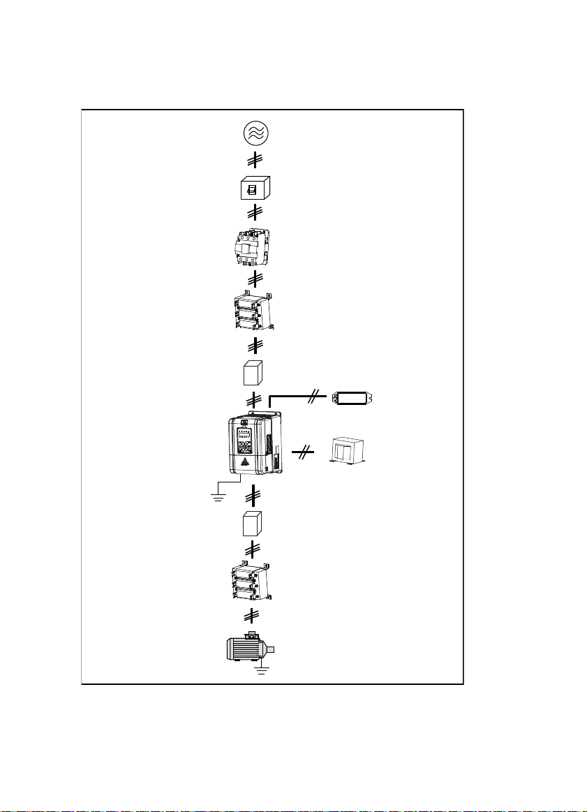
n
n
p
h
Co
ectionwithperi
Three-phase AC power supply
AC input r eactor
eral devices
MCCB
Contactor
(accessory)
EMI filter
Braking resistor
(accessory)
HD31
EMI filter
AC output reactor
(accessory)
Motor
DC reactor
(accessory)

Version and Revision Records
The version information is on top of the backbone and the bottom left of the cover.
Time: 2017/07
Version: V1.1
Revised chapter Revised contents
• New model: HD31-4T2P2P, HD31-4T3P7P
• Refer to 2.3 Rated Value, 4.2.1 Wiring specifications of input and output, 9.3 Braking
Resistor and Braking Unit for details
• Modify the input and output lines, see 4.2.1
• New content: 4.2.2 Power terminal lug.
• Add adjustment in switching from variable frequency to power frequeny, see 7.2
• Add fault: E00.37 (Input wrong phase), see Chapter 8
Chapter 6
Appendix A
• Change the pressure unit to: kg/cm2
• Concrete parameter: P00.05, P02.01, P02.04, P02.06, P02.08, P02.10, P02.12, P02.14, P02.16,
P02.18, P02.20, P02.22, P02.24, P02.26, P04.00, P04.02
• Add d00.42 (Set water supply pressure), d00.43 (Actual water supply pressure)
• Add F00.04 (Extension card selection)
• F15.00 – F15.08 (DI function) add: 54 Clear fault records
• F18.02 – F18.13 (Set parameter of run/stop status) modify:
• Add: 35 (Content water supply pressure setting), 36(Actula feedback pressure)
• F18.04, F18.12, F18.13 modify default
• P00.07 (Dormancy enable) add: 3 (No flow dormancy 1), 4 (No flow dormancy 2)
• Modify defination of P00.13, P00.14
• Add P00.23 – P00.30 ((no-flow power function), P00.31 – P00.38 (function of switching from
variable frequency to power frequency), P00.39 – P00.50 (pump contactor function)
• P02.28 (Proportional gain of pressure closed-loop) modify default and range: 0.00 – 10.00
[0.01]
• Add P02.35 (Digital setting for saving selection when power failure)
• Add P05.03 – P05.04 (pressure sensor function), P05.05 ( Water supply method)


CONTENTS
Chapter 1 Safety Information and Precautions .................................................................................................... 1
1.1 Safety Definition ............................................................................................................................... 1
1.2 About Motor and Load ..................................................................................................................... 1
1.3 About HD31 ....................................................................................................................................... 2
Chapter 2 Product Information ............................................................................................................................... 5
2.1 Model .................................................................................................................................................. 5
2.2 Nameplate .......................................................................................................................................... 5
2.3 Rated Value ........................................................................................................................................ 6
2.4 Technical Data ................................................................................................................................... 6
2.5 Parts of Inverter ................................................................................................................................. 8
Chapter 3 Machenical Installation .......................................................................................................................... 9
3.1 Precautions ........................................................................................................................................ 9
3.2 Installation Site Requirement ......................................................................................................... 9
3.3 Installation Direction and Space Requirements ........................................................................ 10
3.4 Dimensions and Weight ................................................................................................................. 11
3.5 Install and Dismantle Keypad ....................................................................................................... 12
3.6 Dismantle Plastic Cover ................................................................................................................. 13
Chapter 4 Electrical Installation ............................................................................................................................ 15
4.1 Precautions ...................................................................................................................................... 15
4.2 Peripheral Accessories Selection .................................................................................................. 15
4.2.1 Wiring specifications of input and output......................................................................................... 15
4.2.2 Power terminal lug .................................................................................................................................... 16
4.3 Main Circuit Terminals and Wiring ............................................................................................... 16
4.3.1 Supply and Motor Terminal .................................................................................................................... 17
4.3.2 Supply and Motor Connection .............................................................................................................. 18
4.4 Control Board and I/O Board ......................................................................................................... 19
4.4.1 Control Board Terminal ............................................................................................................................ 20
4.4.2 I/O Board Terminal ..................................................................................................................................... 21
4.4.3 Modbus Communication Terminal ...................................................................................................... 21
4.4.4 Jumper ........................................................................................................................................................... 22
Chapter 5 Keypad .................................................................................................................................................... 23
Chapter 6 Function Introduction .......................................................................................................................... 25
6.1 Group d: Display Parameters ........................................................................................................ 26

6.1.1 d00: Status Display Parameters ............................................................................................................. 26
6.2 Group F: General Parameters ........................................................................................................ 29
6.2.1 F00: Basic Parameters ............................................................................................................................... 29
6.2.2 F01: Protection of Parameters................................................................................................................ 32
6.2.3 F03: Acc / Dec Parameters ....................................................................................................................... 33
6.2.4 F05: External Setting Curve Parameters ............................................................................................. 33
6.2.5 F08: Asynchronous Motor Parameters................................................................................................ 35
6.2.6 F09: V/f Control Parameters .................................................................................................................... 36
6.2.7 F15: Digital I/O Terminal Parameters ................................................................................................... 38
6.2.8 F16: Analogue I/O Terminal Parameters ............................................................................................. 41
6.2.9 F17: SCI Communication Parameters .................................................................................................. 43
6.2.10 F18: Display Control Parameters ........................................................................................................ 44
6.2.11 F19: Function-boost Parameters ........................................................................................................ 45
6.2.12 F20: Fault Protection Parameters ....................................................................................................... 47
6.2.13 F23: PWM Control Parameters ............................................................................................................. 50
6.3 Group P: Special Parameter for Multi-pump Water Supply ...................................................... 51
6.3.1 P00: Water Supply Logic Parameter ..................................................................................................... 51
6.3.2 P01: Water Supply Pump Parameter .................................................................................................... 56
6.3.3 P02: Water Supply PID Parameter ......................................................................................................... 57
6.3.4 P03: Water Supply AIO Function Parameter ..................................................................................... 59
6.3.5 P04: Water Supply Fault Protection Parameter ................................................................................ 61
6.3.6 P05: Water Supply Time Parameter ...................................................................................................... 61
Chapter 7 Application Reference .......................................................................................................................... 63
7.1 Take one-to-six inverter as an example. ...................................................................................... 63
7.2 Debugging for Switching between VF and IF ............................................................................ 66
Chapter 8 Troubleshooting ................................................................................................................................... 67
Chapter 9 Accessories ............................................................................................................................................. 71
9.1 Keypad Installation Assembly ...................................................................................................... 71
9.2 Reactor Selection ............................................................................................................................ 71
9.3 Braking Resistor and Braking Unit ............................................................................................... 72
Appendix A Parameters ......................................................................................................................................... 73

Safety Information and Precautions
Product Information
Machenical Installation
Electrical Installation
Keypad
Function Introduction
Application Reference
Troubleshooting
Accessories
Parameters
1
2
3
4
5
6
7
8
9
A

Shenzhen Hpmont Technology Co., Ltd. Chapter 1 Safety Information and Precautions
W
Chapter 1 Safety Information and Precautions
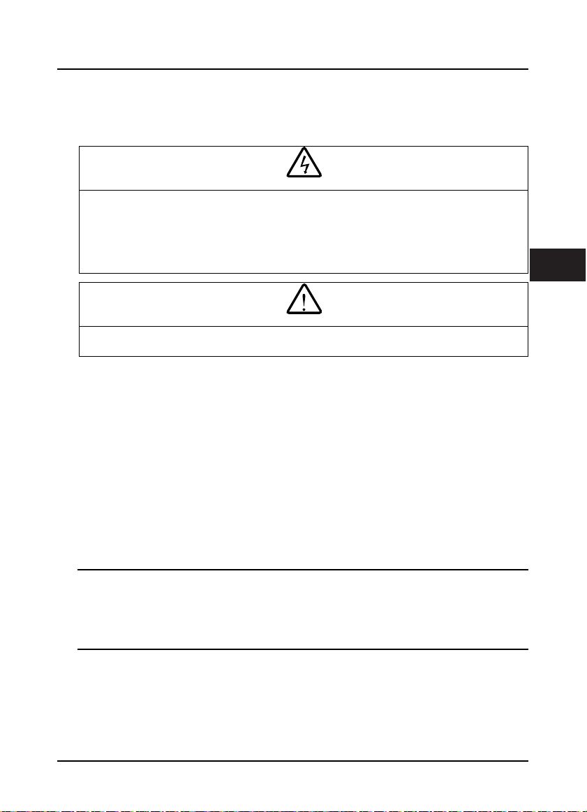
1.1 Safety Definition
Danger
arning
Note
A Danger contains information which is critical for avoiding safety hazard.
Danger:
A Warning contains information which is essential for avoiding a risk of damage to products or other
Warn ing:
equipements.
A Note contains information which helps to ensure correct operation of the product.
Note:
1.2 About Motor and Load
Compared to the industrial frequency running
The HD31 series inverters are voltage-type frequency inverters and their output is PWM wave with
certain harmonic wave. Therefore, the temperature, noise and vibration of the motor will be a little
higher than that at industrial frequency running.
Constant torque at low-speed running
When HD31 drives a standard motor at low-speed running for a long time, the output torque ratings
will become worse due to the motor cooling is less effective. In that case, we suggest that you should
choose variable frequency motor.
Thermal protection of motor
When choose the adaptive motor, HD31 can effectively implement thermal protection of motor.
Otherwise it must adjust the motor protection parameters or other protection measures to ensure that
the motor is at a safe and reliable running.
Running above the rated frequency of motor
If the motor runs exceeding its rated frequency, the noise will increase. Pay attention to the motor
vibration as well as ensure the motor bearings and mechanical devices to meet the requirement of
running speed range.
Lubrication of mechanical devices
At long time low-speed running, provide periodical lubrication maintenance for the mechanical
devices such as gear box and geared motor etc. to make sure the drive results meet the site need.
1
HD31 Series User Manual V1.1 ―1―

Chapter 1 Safety Information and Precautions Shenzhen Hpmont Technology Co., Ltd.
Mechanical resonance point of load
Set the skip frequency (F05.17 - F05.19) to avoid the load device or the motor mechanical resonance
point.
Start and stop HD31
User should use the control terminal to start and stop HD31.
It is strictly forbidden to use contactor or other switches on the input side of HD31 to start and stop
directly, or it will damage the device.
Check the insulation of the motor
For the first time using of the motor or after long time storage, it needs checking the insulation of the
motor. Worse insulation can cause damage to HD31.
Note:
Use a 500V Mega-Ohm-Meter to test and the insulation resistance must be higher than 5Mohm.
Load and negative torque
For the occasion to boost load and the like, negative torque often occurs. Consider setting proper
parameters of the braking unit if HD31 is prone to overcurrent or overvoltage fault trip.
Requirement for leakage current protector RCD
Since the device generates high leakage current which goes through the protective grounding
conductor, please install B type leakage current protector RCD on one side of the power supply.
For the selection of RCD, users need to consider the possible problems of ground leakage current in
both transient status and steady status at start and during running. It is recommended to choose
either special RCD that can suppress the higher harmonics, or general RCD that has more aftercurrent.
Warning for ground mass leakage current
The device generates mass leakage current, so users need to confirm the reliable grounding before
connect to the power supply. The grounding should comply with the local relative IEC standard.
1.3 About HD31
No capacitor or varistor on the output side
Since HD31 output is PWM wave, it is strictly forbidden to connect capacitor for improving the power
factor or varistor for lightning protection to the output terminals so as to avoid HD31 fault trip or
component damage.
Contactors and circuit breakers connected to the output of HD31
If circuit breaker or contactor needs to be connected between HD31 and the motor, be sure to operate
these circuit breakers or contactor when HD31 has no output, so as to avoid any damage to HD31.
Running voltage
HD31 is prohibited to be used beyond the specified range of running voltage. If needed, please use
suitable voltage regulation device to change the voltage.
―2― HD31 Series User Manual V1.1
Shenzhen Hpmont Technology Co., Ltd. Chapter 1 Safety Information and Precautions
Capacitor energy storage
When the AC power supply is cut off, capacitor of HD31 sustains deadly power for a while. So to
disassemble HD31 that is powered, please cut off the AC power supply for more than 10 minutes,
confirm the internal charge indicator is off and the voltage between (+) and (-) of the main circuit
terminals is below 36V.
Generally, the internal circuit enables the capacitor to discharge. However, the discharging may fail in
some exceptions. In these cases, users need to consult Hpmont or our regional distributor.
Lightning surge protection
HD31 internal design has lightning surge overcurrent protection circuit, and has certain self-protection
capacity against the lightning.
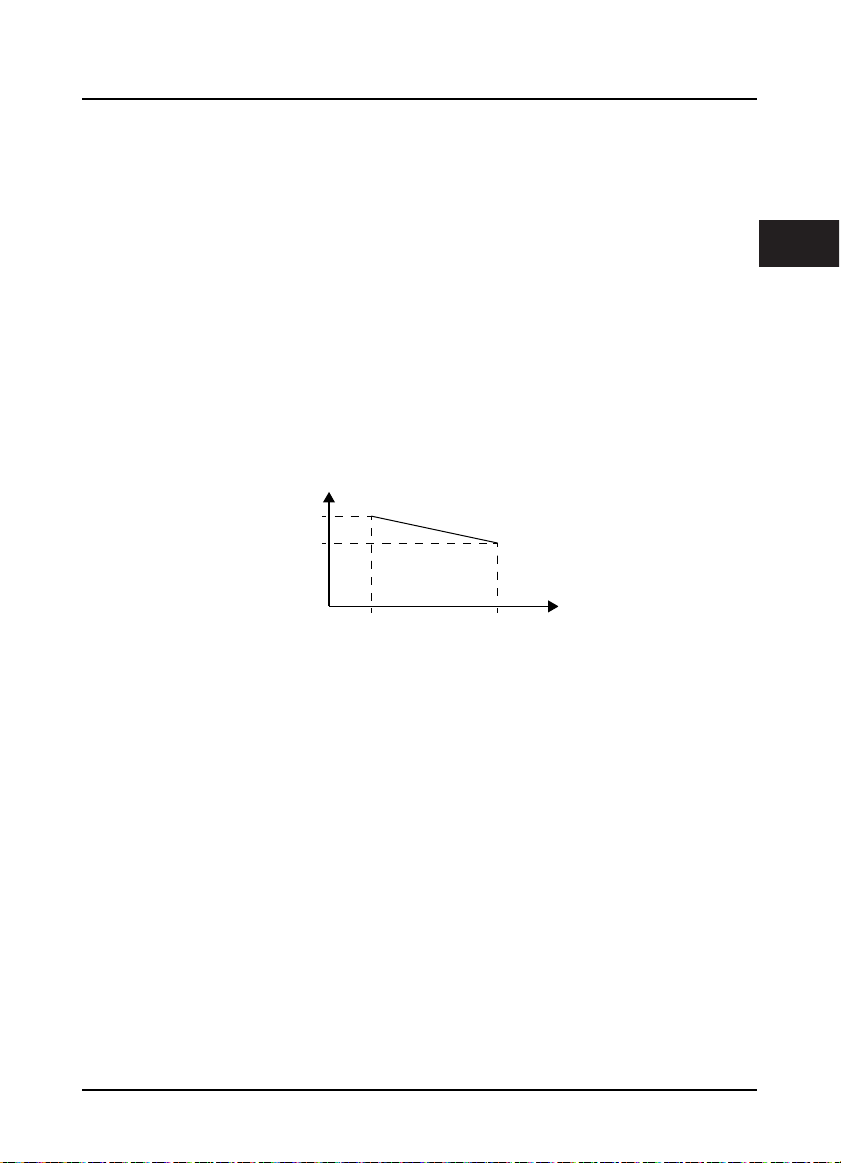
Altitude and derating
In area where altitude exceeds 1000 meters, HD31 should be derating since the heatsink efficiency will
be reduced because of the tenuous air.
The rated value of output current derates by 1% for each 100m increase of the altitude. I.e. for the
altitude of 4000m, derated rate is 30% for rated current of HD31. Figure 1–1 is the derating curve of
rated current and the altitude.
Rated current of HD31
100%
70%
Altitude
1000m 4000m
Figure 1–1 Derating curve of rated current and altitude
1
HD31 Series User Manual V1.1 ―3―

Shenzhen Hpmont Technology Co., Ltd. Chapter 2 Product Information
Chapter 2 Product Information
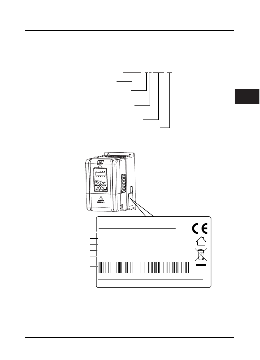
2.1 Model
HD31-4T7P5-P
Product Series
Power Supply Voltage
380 - 460VAC = 4
Input Phase
Three-phase input = T
Power
Product Type
2.2 Nameplate
Fan and pump = P
FWD
REV
ALM
LOCK
LO/RE
HZ
A
V
RPM %
2
Product model
Motor power
Input specification
Output specification
Software version
MODEL:
POWER:
INPUT:
OUTPUT:
HD31-4T7P5P
7.5kW
3PH 380-460V 19A 50/60Hz
11kVA 0-460V 17A 0-400Hz
1.00Version:
Serial number
HD31 Series User Manual V1.1 ―5―
Chapter 2 Product Information Shenzhen Hpmont Technology Co., Ltd.
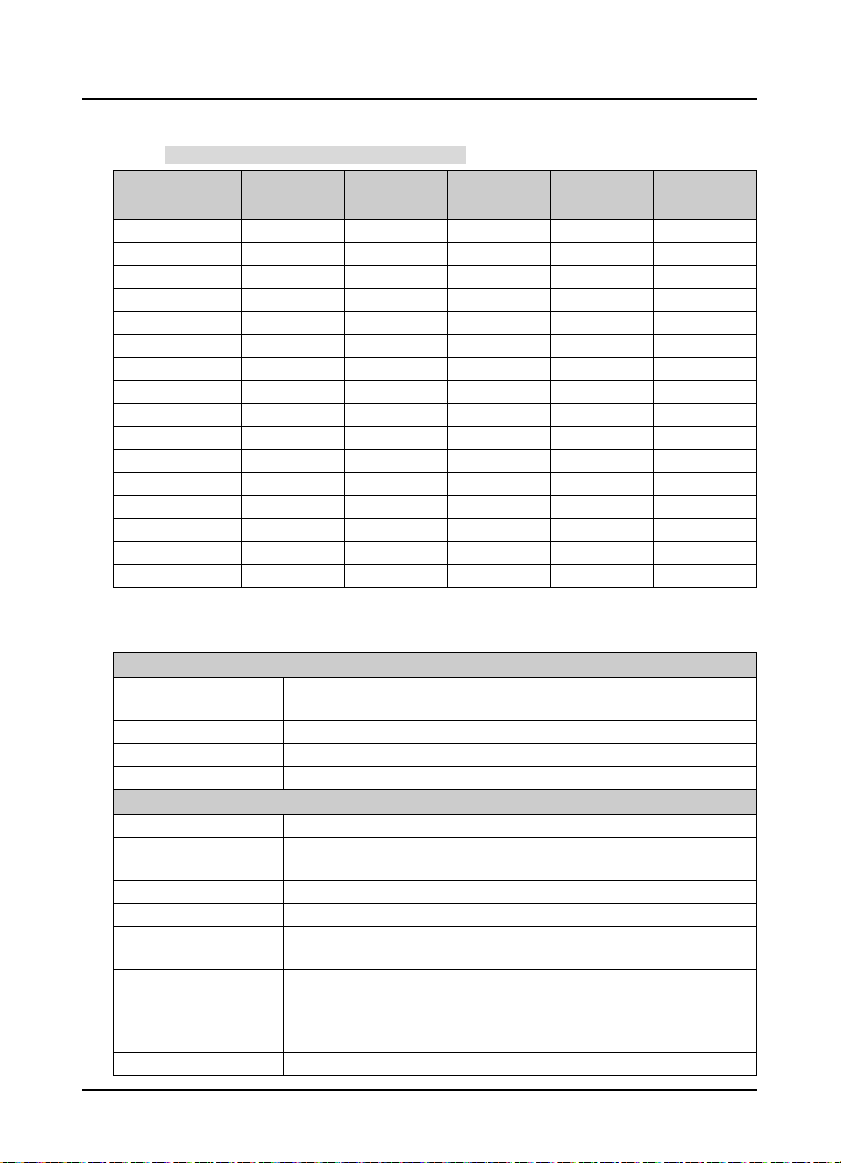
2.3 Rated Value
Refer to section 3.4 Dimensions and Weight (on page 11) for size information.
Model
HD31-4T2P2P 2.2 3.4 7.3 5.1 F2
HD31-4T3P7P 3.7 5.9 11.9 9.0 F2
HD31-4T5P5P 5.5 8.5 15 13 F2
HD31-4T7P5P 7.5 11 19 17 F2
HD31-4T011P 11 16 28 25 F3
HD31-4T015P 15 21 35 32 F3
HD31-4T018P 18.5 24 39 37 F4
HD31-4T022P 22 30 47 45 F4
HD31-4T030P 30 39 62 60 F5
HD31-4T037P 37 49 77 75 F5
HD31-4T045P 45 59 92 90 F6
HD31-4T055P 55 72 113 110 F6
HD31-4T075P 75 100 156 152 F6
HD31-4T090P 90 116 180 176 F7
HD31-4T110P 110 138 214 210 F7
HD31-4T132P 132 167 256 253 F7
Motor
(kW)
Rated Capacity
(kVA)
Rated Input
Current (A)
Rated Output
Current (A)
Size
2.4 Technical Data
Electrical
Input voltage
Input frequency 50/60Hz ± 5%
Output voltage 0 - input voltage
Output frequency 0 - 400.00Hz
Perf orman ce
Control mode V/f, SVC
Max. current
Running command Keypad; Terminals; Communication
Speed setting Digital; Analogue; Communication
Speed resulotion
SVC
Torque control accuracy ±5%
Three-phase: 380 - 460V, 50/60Hz
Fluctuating within ± 10%, imbalance rate < 3%
120% rated output current for 5 minutes;
135% rated output current for 35 seconds
Digital setting: 0.01Hz
Analogue setting: 0.1% × max-frequency
Speed cont rol accuracy: ± 0 .5%
Speed control range: 1:100
Torque control response: < 200ms
Start torq ue: 180% rated torque / 0.5Hz
―6― HD31 Series User Manual V1.1
Shenzhen Hpmont Technology Co., Ltd. Chapter 2 Product Information
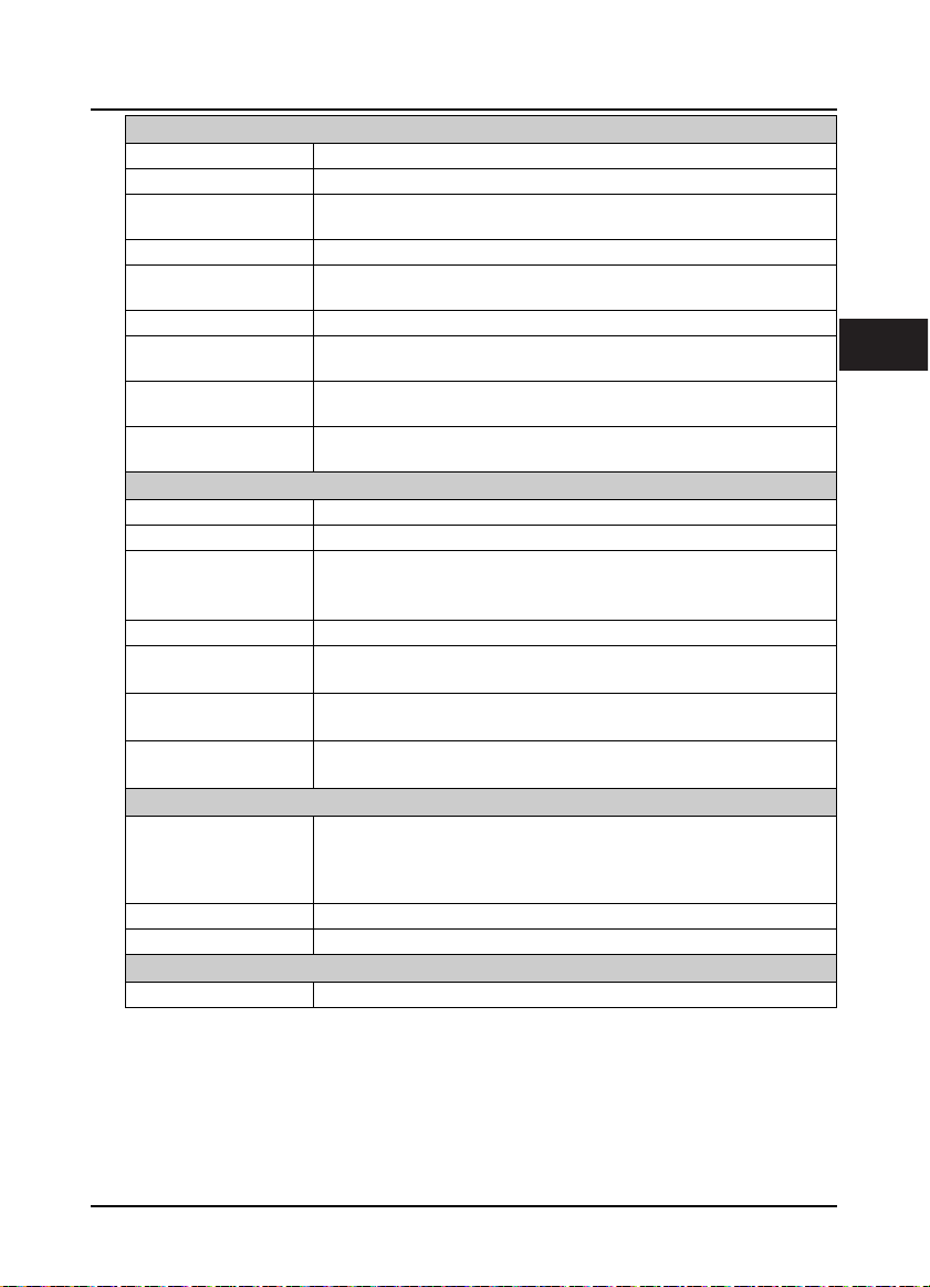
Protection Functions
Stall overvoltage Bus voltage can auto-control against overvoltage fault
Auto-limit current protection Output current can auto-limit against overcurrent fault
Overload pre-alarm and
alarm
Load loss protection Load loss alarm function
Input / Output voltage
phase loss protection
Braking fault protection Braking detection and alarming function
PID commands and
feedback loss detection
Power output grounding
fault protection
Power output short circuit
protection
Input / Outpot
Analogue power supply +10V, max. current 100mA
Digital power supply +24V, max. current 200mA
Analogue input
Analogue output AO1, AO2: 0 - 10V/0 - 20mA (selectable voltage/current)
Digital input
Digital output
Relay output
Keypad
LED display
LCD display Optional [HD-LCD], display contents in Chinese or English
Parameter copy Both LED and LCD keypad can achieve quick parameter copy
Communication
SCI communication RS-485 interface; Terminal
Overload early pre-alarm and protect
Input / Output voltage phase loss auto-detec t and alarm function
PID can auto-identify whether loss the setting and feedback or the alarm function
Power output grounding fault protection is enabled
Power output short circuit protection is enabled
AI1 (control board): voltage 0 - 10V
AI2 (control board): -10 - +10V/0 - 20mA (selectable voltage/current)
AI3, AI4 (I/O board): -10 - +10V/0 - 20mA (selectable voltage/cu rrent)
DI1 - DI6 (control board); DI7 - DI9 (I/O board)
DI6 can be selectable for high-frequency input
DO1, DO2
DO2 can be selectable for high-frequency output
R1A/R1B/R1C(control board), R2A/R2C - R10A/R10C(I/O board)
Contact rating: 250VAC/3A or 30VDC/1A
Five LEDs display, 5 unit indicators, 5 status indicators
Setting frequency, output frequency, output voltage, output current, motor speed,
output torque, switching value terminal, status parameter, programm menu
parameter and fault code etc.
2
HD31 Series User Manual V1.1 ―7―
Chapter 2 Product Information Shenzhen Hpmont Technology Co., Ltd.
e
C
C
Environment
Running temperature
Storage temperature -40 - +70℃
Location for use
Altitude Less than 1000 meters, otherwise should be derating use
Humidity Less than 95%RH, non-condensing
Vibration Resistance It is 3.5m/s2 in 2 - 9Hz, it is 10m/s2 (IEC60721-3-3) in 9 - 200Hz
Protection class IP20
Pollution level Level 2 (Dry, non conducting dust pollution)
Accessorie s
Bus communication
About keypad
Power units Dynamic braking unit [HDBU]
-10 - +40℃, max. 50℃, air temperature fluctuation is less than 0.5℃/min
The derating value of the output current of HD31 shall be 2% for each degree
centigrade above 40℃. Max. allowed temperature is 50℃
Indoor, preventing from direct sunlight, no dust, corrosive, flammable gases, oil mist,
water vaper, dripping or salt etc.
PROFIBUS option [HDFB-PROFIBUS-DP]
DeviceNet option [HDFB-DeviceNet]
CAN option [HDFB-CAN]
LCD k eypad ( HD-LCD)
Mounting base to keypad (HD-KMB)
1m/2m/3m/6m extension cable to keypad (HD -CAB-1M/2M/3M/6M)
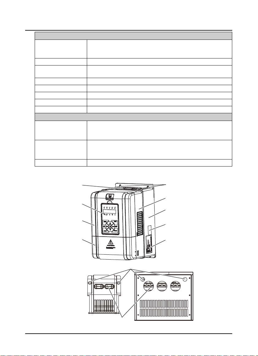
2.5 Parts of Inverter
Fan cover
Keypad
Mounting hole
Middle enclosure
Bottom enclosur
Upper cover
Lower cover
onnection holesofcontrolterminal
Size F2 - F4
onnection holesofpower terminal
Certification
Nameplate
Size F5 - F7
―8― HD31 Series User Manual V1.1
Shenzhen Hpmont Technology Co., Ltd. Chapter 3 Machenical Installation
W
Chapter 3 Machenical Installation
3.1 Precautions
Danger
arning
• Do not install if HD31 is incomplete or impaired.
• When conveying HD31, please employ suitable tools according to its weight. Avoid scratch to the product. Be
careful: rollover and drop may cause hurt.
• Make sure that HD31 is far from explosive and flammable things.
• Do not do wiring operation until power supply is cut off for more than 10 minutes, the internal charge indicator of
HD31 is off and the voltage between (+) and (-) of the main circuit terminals is below 36V.
• It is required not only carry the keypad and the cover but also bottom enclosure of HD31.
• Do not let wires, screws or residues fall into HD31 when installing.
3.2 Installation Site Requirement
Ensure the installation site meets the following requirements:
• Do not install at direct sunlight, moisture, water droplet location;
• Do not install at flammable, explosive, corrosive gas and liquid location;
• Do not install at oily dust, fiber and metal powder location;
• Be vertical installed on fire-retardant material with a strong support;
• Make sure adequate cooling space for HD31 so as to keep ambient temperature between
- 10 - + 40℃;
• Install at where the vibration is 3.5m/s2 in 2 - 9Hz, 10m/s2 in 9 - 200Hz (IEC60721-3-3);
• Install at where the humidity is less than 95%RH and non-condensing location;
• Protection level of HD31 is IP20 and pollution level is 2 (Dry, non-conducting dust pollution).
Note:
1. It needs derating use if running temperature exceeds 40℃. The derating value of the output current of
HD31 shall be 2% for each degree centigrade. Max. allowed temperature is 50℃.
2. Keep ambient temperature between -10 - +40℃. It can improve the running performance if install at
location with good ventilation or cooling devices.
3
HD31 Series User Manual V1.1 ―9―
Chapter 3 Machenical Installation Shenzhen Hpmont Technology Co., Ltd.
D
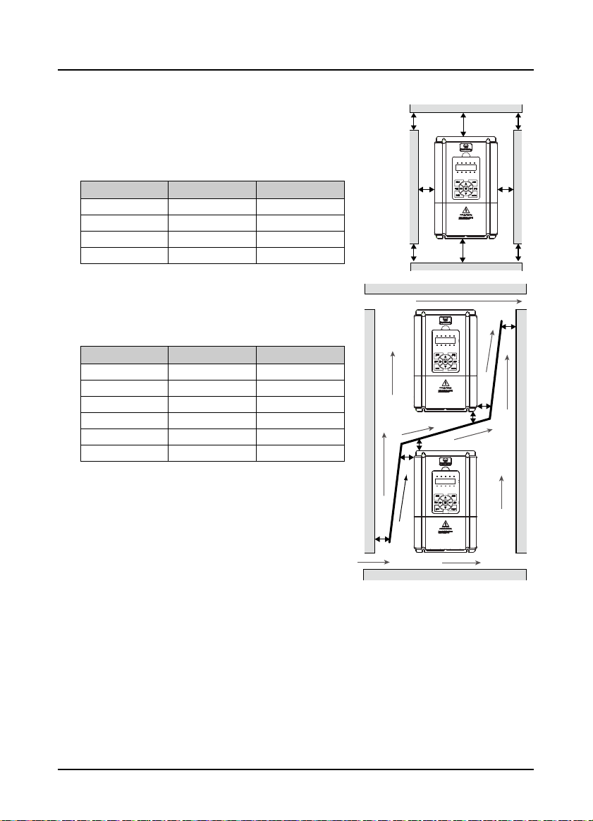
3.3 Installation Direction and Space Requirements
To achieve good cooling efficiency, install the inverter
perpendicularly and always provide the following space to
allow normal heat dissipation. The requirements on mounting
space and clearance are shown in Table 3-1.
Table 3-1 Installation space
HD31 power 5.5 - 75kW 90 - 132kW
A (left and right)
B (up and down)
C (upper vent)
D (lower vent)
123
≥
50mm
≥
100mm
≥
50mm
≥
50mm
≥
150mm
≥
350mm
≥
100mm
≥
100mm
When one inverter is mounted on top of another, an air flow
diverting plate should be fixed between them. Just as shown
in Table 3-2.
Table 3-2 Installation of several inverters
HD31 power 5.5 - 75kW 90 - 132kW
123
A
B
C
a
b
c
≥
≥
≥
≥
≥
≥
50mm
50mm
50mm
50mm
50mm
50mm
≥
100mm
≥
100mm
≥
100mm
≥
100mm
≥
100mm
≥
100mm
C C
B
AA
D
B
a
b
c
C
B
A
―10― HD31 Series User Manual V1.1
Shenzhen Hpmont Technology Co., Ltd. Chapter 3 Machenical Installation
H
H
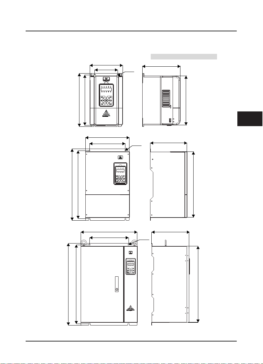
3.4 Dimensions and Weight
The dimensions and weight of HD31 are as shown in Table 3-3.
For the corresponding model of the mounting size, refer to section 2.3 Rated Value, on page 6.
W
W1
4-Ød
D
H1
H1
W
W1
W
W1
Size F2 - F4
4-Ød
Size F5 - F6
H2
3
D
H2
D
4-Ød
H
H1
H2
Size F7
HD31 Series User Manual V1.1 ―11―
Chapter 3 Machenical Installation Shenzhen Hpmont Technology Co., Ltd.
Table 3-3 HD31 dimensions and weight
Size
F2 165 266 190 115 253 245 5 4.4
F3 200 299 210 146 286 280 5 5.8
F4 235 353 222 167 337 330 7 8.2
F5 290 469 240 235 445 430 8 20.4
F6 380 598 290 260 576 550 10 48
F7 500 721 330 343 696 670 12 80
Dimension (mm) Mounting size (mm)
W H D W1 H1 H2 d
GW
(kg)
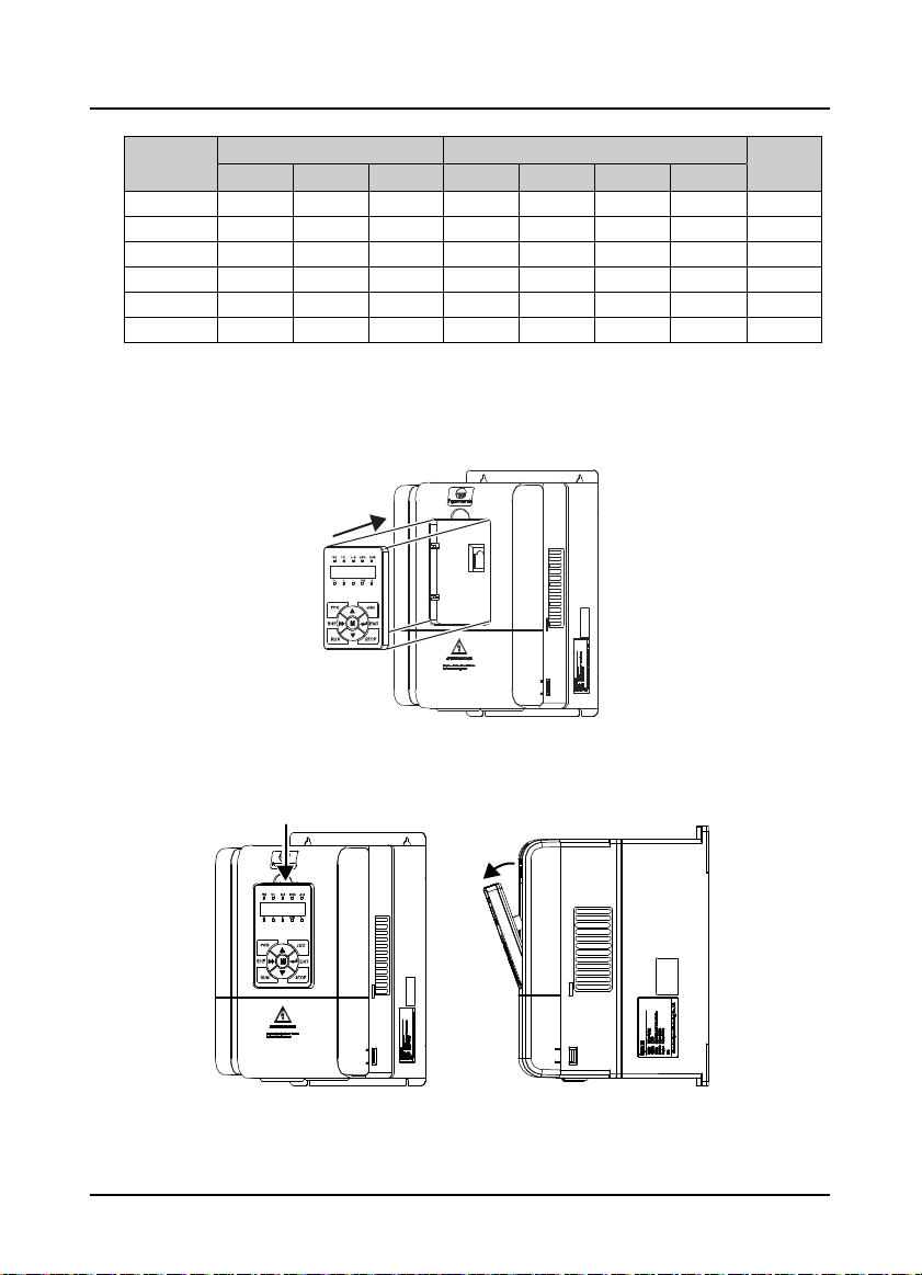
3.5 Install and Dismantle Keypad
According to the direction of Figure 3–1, press the keypad until hear a “click” sound.
Do not install the keypad from other directions or it will cause poor contact.
Figure 3–1 Install keypad
There are two steps in Figure 3–2.
First, press the hook of the keypad according to direction 1. Second, take out of the keypad according
to direction 2.
1
2
Figure 3–2 Dismantle keypad
―12― HD31 Series User Manual V1.1
Shenzhen Hpmont Technology Co., Ltd. Chapter 3 Machenical Installation
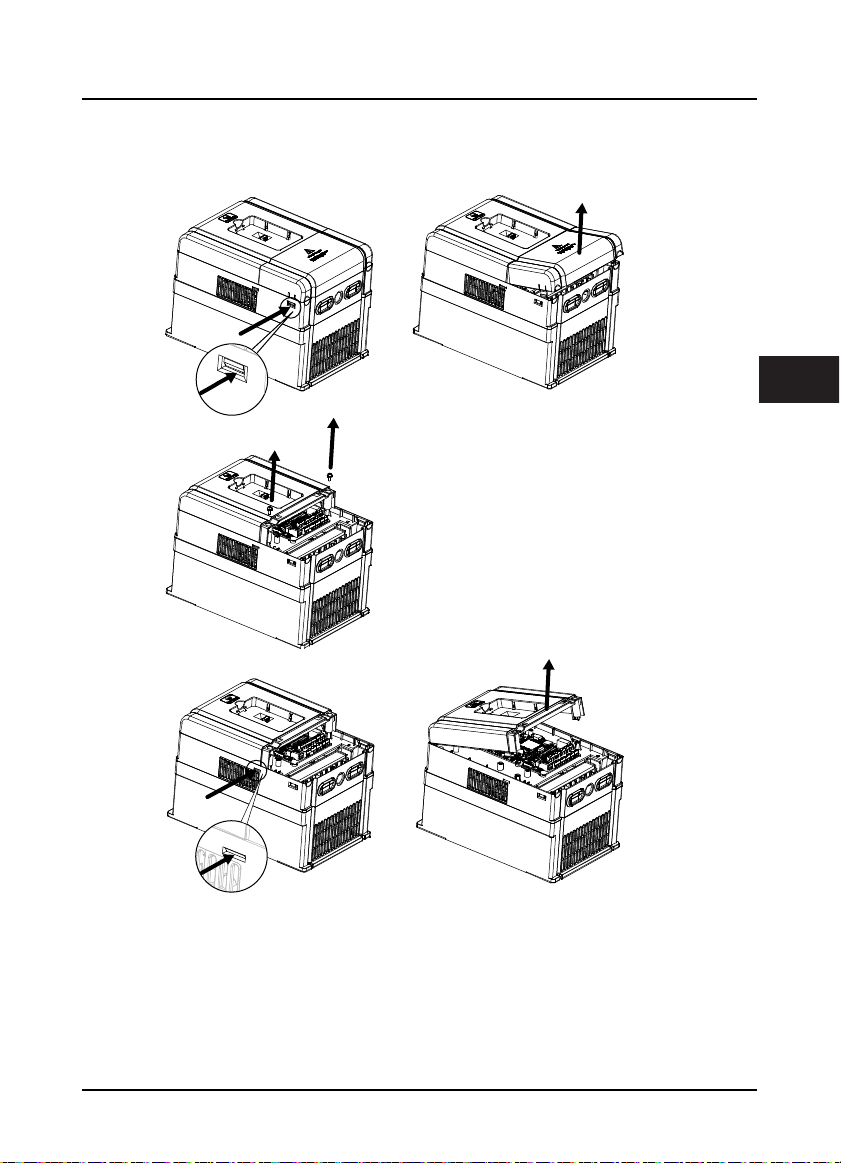
3.6 Dismantle Plastic Cover
The upper cover and lower cover of HD31 are removable. The dismantle steps are shown as Figure 3–3.
Before removing the upper cover, please take away the keypad.
(a)
3
The removing processes of plastic
cover board:
1. Extrude the hooks at both sides together,
take off the lower cover, as (a).
2. Dismantle the screws of upper cover, as (b).
3. Extrude the hooks at both sides together,
take off the upper cover, as (c).
(b)
(c)
Figure 3–3 Dismantle the plastic cover
HD31 Series User Manual V1.1 ―13―

Shenzhen Hpmont Technology Co., Ltd. Chapter 4 Electrical Installation
W
Chapter 4 Electrical Installation
4.1 Precautions
Danger
arning
• Only qualified electrical engineer can perform wiring job.
• Only when the power supply switch is completely off can you do the wiring job.
• You can’t open the inverter cover to do wiring operation until the power is cut-off 10 minutes later. Do not wire or
detach the inverter internal devices at power-on situation.
• Do not do wiring operation until the internal charge indicator of the inverter is off and the voltage between (+)
and (-) of the main circuit terminals is below 36V.
• Check the wiring carefully before connecting emergency stop or safety circuit.
• The earth terminal PE of the inverters must be reliable earthing. It must use t wo separate earth wire due to the
leakage current from the inverter to ground.
• It must use Type B mode when utilize earth leakage protection devices(ELCB/RCD).
• Do not touch the wire terminals of the inverter when it is live. The main circuit terminals is neither allowed
connecting to the enclosure nor short-circuiting.
• Do not do dielectric strength test on the inverter.
• Do wiring connection of the braking resistor or the braking unit according to the wiring figure.
• Make sure the terminals are fixed tightly.
• Do not connect the AC supply cable to the output terminals U, V, W of the inverter.
• Do not connect the phase-shifting capacitors to the output circuit.
• Be sure the inverter has ceased output before switching motor or change-over switches.
• The inverter DC bus terminals must not be short-circuited.
4
4.2 Peripheral Accessories Selection
4.2.1 Wiring specifications of input and output
The AC supply to HD31 must be installed with suitable protection against overload and short-circuits,
i.e. MCCB (molded case circuit breaker) or equivalent device.
The recommended specification of MCCB, contactor & cables are shown as Table 4-2.
The size of ground wire should accord with the requirement in 4.3.5.4 of IEC61800-5-1, as shown in
Table 4-1.
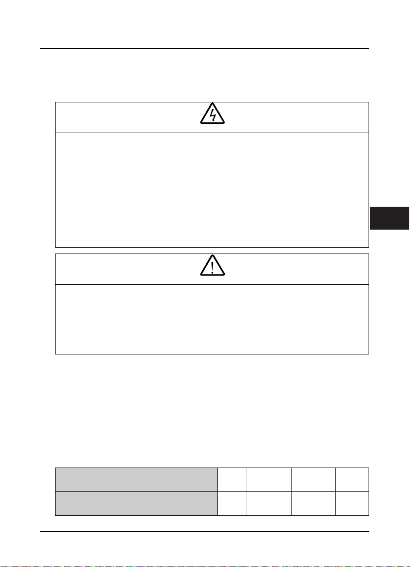
Table 4-1 Sectional area of ground protective conductor
Sectional area S of phase conductor (power supply
cable) while installing (mm2)
Min. sectional area Sp of relative protective conductor
(ground cable) (mm2)
HD31 Series User Manual V1.1 ―15―
S ≤ 2.5 2.5 < S ≤ 16 16 < S ≤ 35 S > 35
2.5 S 16 S/2
Chapter 4 Electrical Installation Shenzhen Hpmont Technology Co., Ltd.
Table 4-2 HD31 I/O wiring specification
Model
HD31-4T2P2P 16 10 1.5 0.75 2.5 F2
HD31-4T3P7P 16 10 2.5 1.5 2.5 F2
HD31-4T5P5P 25 16 2.5 2.5 2.5 F2
HD31-4T7P5P 32 25 4 4 4 F2
HD31-4T011P 40 32 6 6 6 F3
HD31-4T015P 63 40 10 10 10 F3
HD31-4T018P 63 40 10 10 10 F4
HD31-4T022P 100 63 16 16 16 F4
HD31-4T030P 100 63 25 25 16 F5
HD31-4T037P 125 100 35 35 16 F5
HD31-4T045P 160 100 35 35 16 F6
HD31-4T055P 200 125 35 35 16 F6
HD31-4T075P 200 125 50 50 25 F6
HD31-4T090P 250 160 95 70 50 F7
HD31-4T110P 250 160 120 120 50 F7
HD31-4T132P 350 350 120 120 50 F7
MCCB Contacto r Power Cable Motor Cable Ground Cable Size
(A) (A) (mm2) (mm2) (mm2)
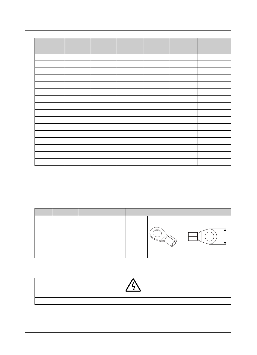
4.2.2 Power terminal lug
Select the lug of power terminal according to the size of terminal, screw size and max. outer diameter
of lug. Refer to Table 4-3.
Take the round terminal as an example.
Table 4-3 Selection of power terminal lug
Size Screw size Tightening torque (N. M) Max. outer diameter of lug d (mm)
F2 M4 1.2 - 1.5 9.9
F3 M5 2.5 - 3.0 12
F4 M5 2.5 - 3.0 12
F5 M6 4.0 - 5.0 15.5
F6 M8 9.0 - 10.0 24
F7 M10 17.6 - 22.5 30
d
4.3 Main Circuit Terminals and Wiring
Danger
• The bare portions of the power cables must be bound with insulation tapes.
―16― HD31 Series User Manual V1.1
Shenzhen Hpmont Technology Co., Ltd. Chapter 4 Electrical Installation
W
arning
• Ensure that AC supply voltage is the same as rated input voltage of HD31.
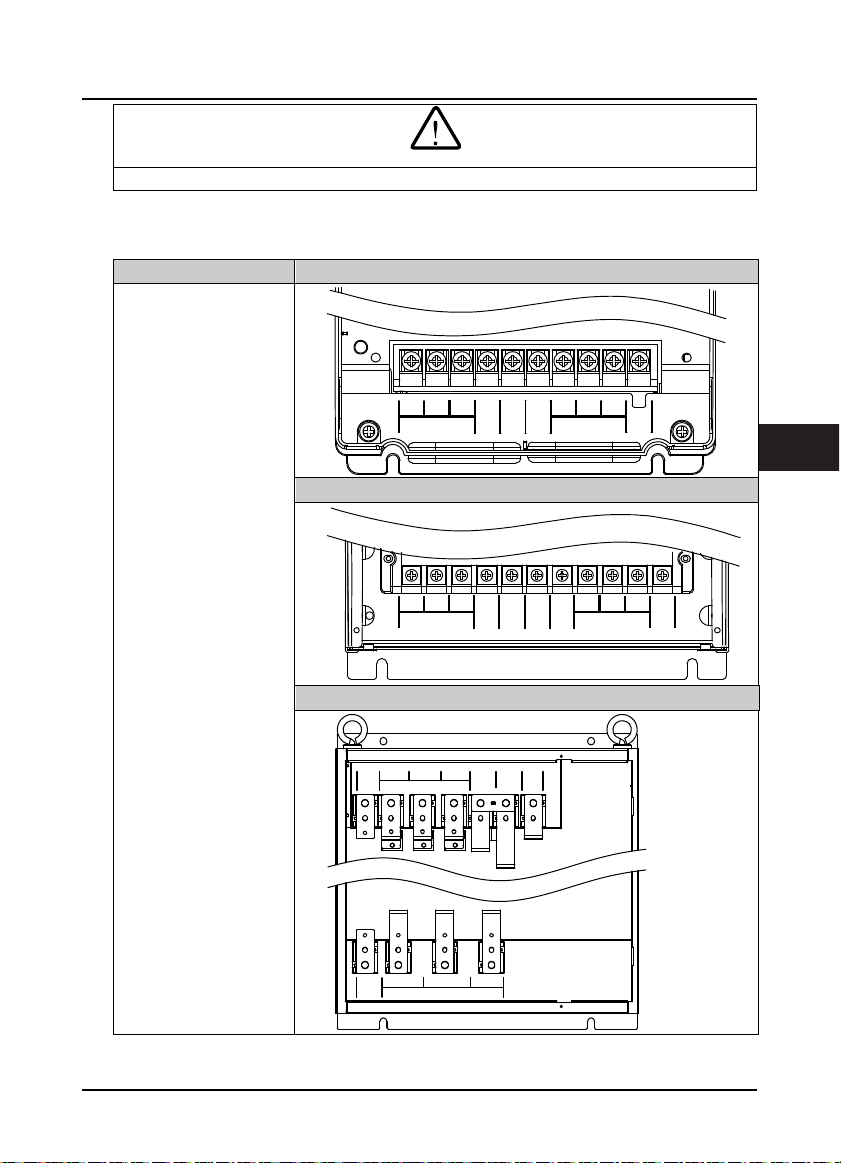
4.3.1 Supply and Motor Terminal
Table 4-4 Supply and motor terminal description
Terminal description Fram e 2
•
L1, L2, L3: Three-phase AC
power input terminals
•
U, V, W: O utput termina ls,
connect to three-phase AC
motor
•
P1, (+):DC reactor
connecti on terminals
•
(+), (-):DC supply input
terminals; DC input
terminals of power
regenerative unit
•
(+), BR: Braking resistor
connecti on terminals
•
PE: Ground terminal,
connect to the ground
Frame 3-Frame 6
Frame 7
L1 L2
PE
PE
L1 L2
L3
L3
MOTOR
(+) (-)
L3
P1
P1
POWER
L1 L2
POWER
POWER
UV
W
(+) (-)
(+) (-)
BR
UV
MOTOR
BR
W
UV
MOTOR
PE
4
W
PE
HD31 Series User Manual V1.1 ―17―

Chapter 4 Electrical Installation Shenzhen Hpmont Technology Co., Ltd.
4.3.2 Supply and Motor Connection
During trial running, make sure HD31 runs forward when the forward command is enabled.
If not, switch any two of the output terminals (U/V/W) or modify parameter F00.17 to change the
motor direction.
The supply and motor connection are shown as Figure 4–1.
Refer to section 4.2 Peripheral Accessories Selection (on page 15) for product options.
Refer to section 9.3 Braking Resistor and Braking (on page 72) for braking resistors and braking units.
Refer to section 9.2 Reactor Selection (on page 71) for AC reactors and DC reactors.
Size F2 connection Size F3 - F6 connection
L1 L2 L3 (+) (-) BR U V W PE
L1 L2 L3 (+) (-) BR U V W PEP1
EMI filter
AC reactor
Mains supply
Braking resistor
MCCB
Contactor Contactor
Supply
ground
L1 L2 L3 (+) (-)PE P1 UV WPE
EMI filter
Supply
ground
AC reactor
Mains supply
DC
reactor
MCCB
Contactor
Figure 4–1 Supply and motor connection
EMI filter
AC reactor
Mains supply
Size F7 connection
Braking
resistor
BR1 BR2(+) (-)
Braking unit
reactor
MCCB
DC
Supply
ground
Braking
resistor
Supply
ground
―18― HD31 Series User Manual V1.1

Shenzhen Hpmont Technology Co., Ltd. Chapter 4 Electrical Installation
W
C
4.4 Control Board and I/O Board
Danger
arning
• The control circuit is basically isolated with the power circuit. Do not touch HD31 after it is powered.
• If the control circuit is connected to the external devices with live touchable port, it should increase an additional
isolating barrier to ensure that classification of external devices not be changed
• If connect the communication terminal of the control circuit to the PC, choose RS485/232 isolating converter
which meets the safety requirement.
• Only connect the relay terminal to AC 220V voltage signal. Other control terminal are strictly forbiden for this
connection.
HD31 includes control board and I/O board, as shown in Figure 4–2.
I/O Board
ontrol Board
4
Figure 4–2 Control board and I/O board
HD31 Series User Manual V1.1 ―19―
Chapter 4 Electrical Installation Shenzhen Hpmont Technology Co., Ltd.
4.4.1 Control Board Terminal
Control Board
Ter min al
+10 A I1 AI2 DI1 DI2 DI3 DI 4 DI5 DI6 COM R1ACOM
GND
Ter mi na l Description
+10, GND
AI1, AI2 Analogue input
AO1, AO2 Analogue output
GND Analogue ground
DI1 - DI6 Digital input
P24, COM
SEL
DO1, CME Digital output
DO2, COM Digital output
R1A/R1B/R1C Relay output
Analogue power
supply
Digital power
supply
Digital input
common terminal
Note:
Limit the current within 3A if the relay terminal is to connect to AC 220V voltage signal.
―20― HD31 Series User Manual V1.1
AO1 AO2
Table 4-5 Control board terminal description
P24 SEL DO1 R1CGND COM CME DO2 R1B
Figure 4–3 Control board term inal
Analogue input use +10V power supply, max. output current is 100mA
GND is isolated to COM
AI1 Input voltage: 0 - 10V (input im pedance: 32kΩ)
AI2 Input voltage: -10 - +10V (input impedance: 32kΩ)
AI2 Input current: 0 - 20mA (input impedance: 500Ω)
• AI2 can be voltage / current selectable
Output voltage / current signal: 0 - 10V/0 - 20mA
Program mable output
Programmable bipolar optional input signal
Input voltage: 0 - 30VDC
DI1 - DI5 input impedance 4.7kΩ, DI6 input i mpedance 1.6kΩ
• DI6 can be selectable for high-frequency input, max-frequency 50kHz
Analogue input use +24V power supply, max. output current is 200mA
COM is isolated to CME
SEL and P24 are connected by default
• Disconnected SEL and P24 when use external power to drive DI
Programmable optical-couple isolation, open collector output
• Output voltage: 0 - 30VDC, max-output current 50mA
• DO2 can be selectable for pulse frequency output, max. frequency 50kHz
CME is isolated to COM, connected to COM by default
• Disconnect CME and COM when they are isolating output
Programmable output, contact rating: 250VAC/3A or 30VDC/1A
• R1B, R1C: normally closed; R1A, R1C: normally open
Shenzhen Hpmont Technology Co., Ltd. Chapter 4 Electrical Installation
C
A
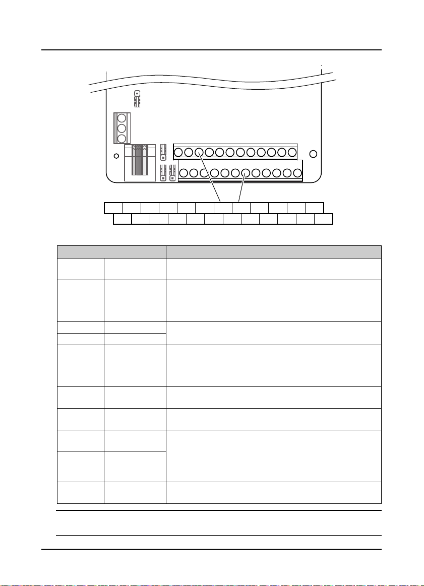
4.4.2 I/O Board Terminal
I/O Board
Ter min alTer min al
R10AR9AR2A R3A R4A R5A R6AR2A R3A R4A R5A R6A R7A R8A
R2A R3A R4A R5A R6A R10
Figure 4–4 I/O board ter minal
Table 4-6 I/O board terminal description
Ter mi na l Funct ion Des cription
AI3 / AI4 Analogue input
+10 / GND
DI7 - DI9 Digital input
P24, COM Digital power supply Digital input use +24V as supply, max. output current is 200mA
SEL
R2A/R2C R10A/R10C
Analogue power
supply
Digital input
common terminal
Relay output
Input voltage: -10 - +10V (input impedance: 32kΩ)
Input current: 0 - 20mA (input impedance: 500Ω)
Analogue input use +10V as supply, max. output current is 100mA
Programmable bipolar optional input, low le vel is effective by default.
Input voltage: 0 - 30VDC (input im pedance: 4.7kΩ)
SEL and P24 are connected by default
• Disconnected SEL and P24 when use external power to drive DI7 - DI9
Programmable normally open output
Contact rating: 250VAC / 3A or 30VDC / 1A
R9CR2C R3C R4C R5C R6C R7C R8C
Note:
Limit the current within 3A if the relay terminal is to connect to AC 220V voltage signal.
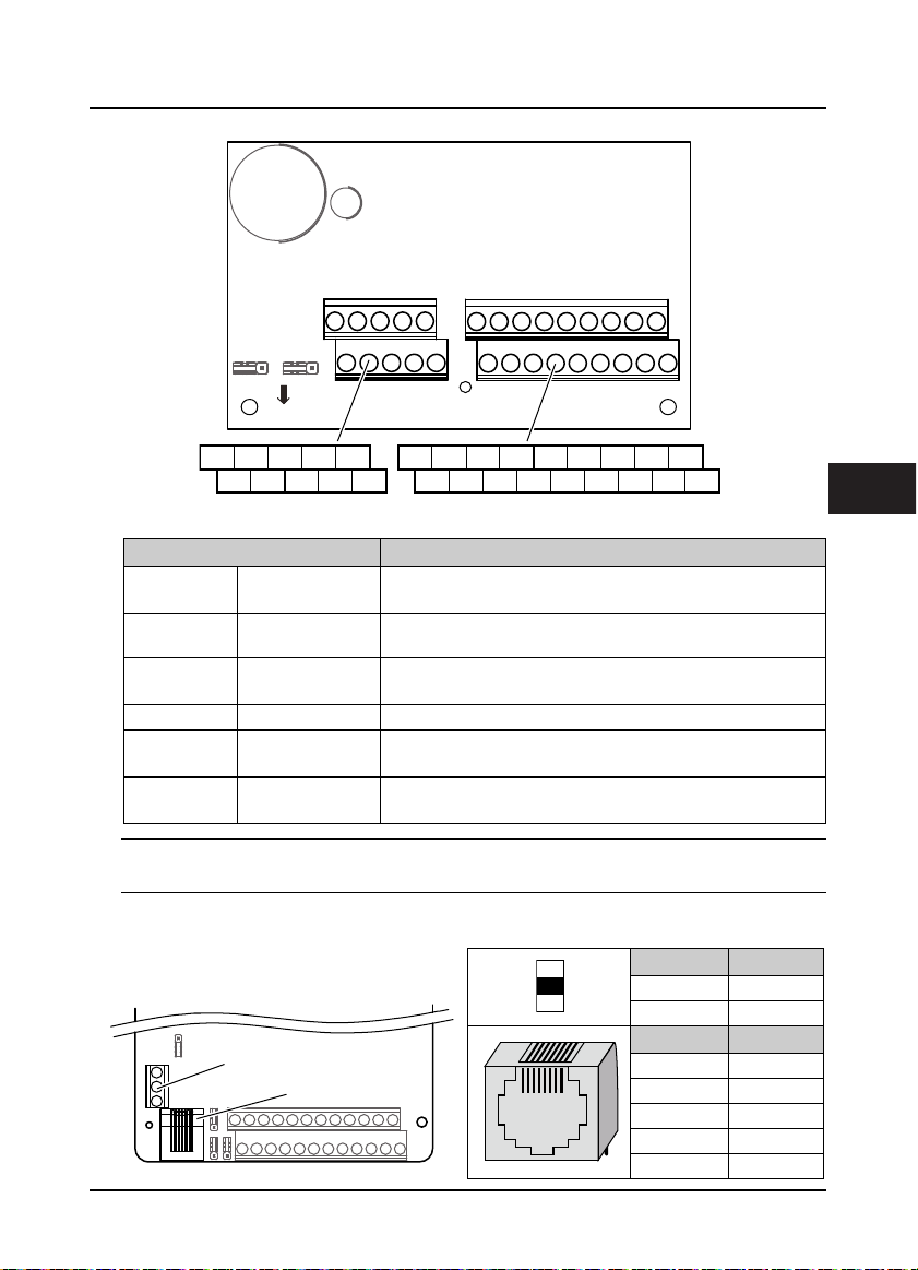
4.4.3 Modbus Communication Terminal
Do not use communication terminal and RJ45
simultaneously.
Ter min al
Control Board
RJ45
B
18
RJ45
Ter mi na l Description
A 485+
B 485-
Pin Difinition
1,3 +5V
2 485+
4,5,6 GND
7 485-
8 Unused
4
HD31 Series User Manual V1.1 ―21―
 Loading...