

Page 1

V1.1 2017.07
HD09 Series
Smart Inverter
User Manual
Single-phase 220 - 240V, 0.25 - 2.2kW
Three-phase 380 - 460V, 0.4 - 5.5kW
Page 2

FOREWORD
Thank you for purchasing HD09 series smart inverter manufactured by Shenzhen
Hpmont Technology Co., Ltd.
This User Manual describes how to use HD09 series inverters and their installation
wiring, parameter setting, troubleshooting and daily maintenance etc.
Before using the product, please read through this User Manual carefully. In addition,
please do not use this product until you have fully understood safety precautions.
Note:
Preserve this Manual for future use.
If you need the User Manual due to damage, loss or other reasons, please contact
the regional distributor of our company or directly contact our company Technical
Service Center.
If you still have some problems during use, please contact our company Technical
Service Center.
Due to product upgrade or specification change, and for the purpose of
improving convenience and accuracy of this manual, this manual’s contents may
be modified.
Telephone: 4008-858-959 or 189 4871 3800
Page 3

Version and Revision Records
Version information: At the bottom right corner of the front cover.
Time: 2017/07
Version: V1.1
Revised chapter Revised contents
Chapter 4
Chapter 5
• AI termials can be selected as DI input, see clause 4.2
• Modify input and output routh, see clause 5.1.1
• Add selection of power terminals wiring lugs, see clasue 5.1.2
Chapter 8 • Add F00.17 (Running direction), F00.19 (Dead time from positive rotation to oppositve
rotation), F00.20 (External keypad), F00.21 – F00.25 (Sleep function)
• Add parameter copy function: F01.02 add function 2/3, add parameter F00.13
• Add F03.03 – F03.16 (Ace. and Dec. parameter)
• Modify F04.16 (Integral regulation selection) default value: [0]
• Modify F06.01 - F06.06 (Multi-frequency) default value: [5.0Hz]
• Add F08.04 (Rated Rpm of motor)
• Add F09.09 – F09.12 (Motor compensation function), F09.14 (Auto-voltage adjustment
function). Modify defination of F09.15: Oscillation-suppression mode
• Add F15.44 (AI as function of DI). DI function (F15.00 – F15.03, F15.44) add: 26/27 (Ace. and
Dec. time selection)
• Modify F17.03 (Host PC response time) default: [1ms], add F17.10 (Detecting time when
network communication over time)
• Add group F18 (Display control parameter)
• Add F19.12 – F19.15 (Instant power failure without stop), F17.37 (Frequency adjust range),
F17.39 (Input voltage)
• Add F20.00 (Over-load protection function)
Page 4

CONTENTS
Chapter 1 Safety Information .................................................................................................................................. 1
Chapter 2 Product Information ............................................................................................................................... 3
2.1 Nameplate ................................................................................................................................................................. 3
2.2 Rated Value ............................................................................................................................................................... 4
Chapter 3 Machenical Installation .......................................................................................................................... 5
3.1 Dimension and Weight ......................................................................................................................................... 5
3.2 Requirement for the Installation Site .............................................................................................................. 6
3.3 Installation of Exterior Keypad ........................................................................................................................... 7
Chapter 4 Electrical Installation .............................................................................................................................. 9
4.1 Power Terminals and Connection ................................................................................................................... 10
4.2 Control Terminals and Connection ................................................................................................................. 11
4.3 External Keypad or Upper Computer ............................................................................................................ 14
Chapter 5 Technical Data ....................................................................................................................................... 15
5.1 Peripheral Accessories Selection ..................................................................................................................... 15
5.2 Braking Resistor ..................................................................................................................................................... 16
5.3 Technical Data ........................................................................................................................................................ 17
Chapter 6 Keypad .................................................................................................................................................... 19
Chapter 7 Troubleshooting .................................................................................................................................... 21
Chapter 8 Parameter ............................................................................................................................................... 25
Page 5

Page 6
Shenzhen Hpmont Technology Co., Ltd. Chapter 1 Safety Information
HD09 Series User Manual V1.1 -1-
Chapter 1 Safety Information
Safety Definition
Pay attention to contents with following marks in the user manual or on the product.
Danger: A Danger contains information which is critical for avoiding safety hazard.
War ning: A Warning contains information which is essential for avoiding a risk of damage to products or other
equipements..
Note: A Note contains information which helps to ensure correct operation of the product.
Professional Staff
Only qualified electrical engineer can perform electrical installation.
Only professional staff that received special training and authorized can carry out maintenances.
Danger
W
arning
Note
Page 7

Page 8
Shenzhen Hpmont Technology Co., Ltd. Chapter 2 Product Information
HD09 Series User Manual V1.1 -3-
Chapter 2 Product Information
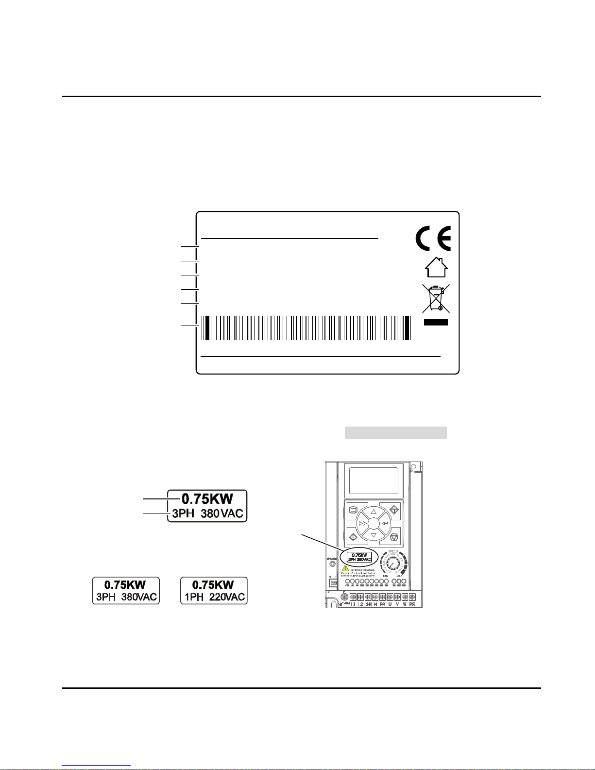
2.1 Nameplate
Nameplate Label
Name plate label is pasted on right side of the product. Its contents are shown in the following figure.
Power Label
Power label is below the keypad for recognizing the products easily and quickly.
Power label includes motor power and supply voltage. See 2.2 Rated Value, page 4.
Its contents are shown in the following figure.
MODEL:
HD09-4T0P7G
0.75kW
POWER:
3PH 380-460V 3.4A 50/60Hz
INPUT:
1.5kVA 0-460V 2.3A 0-1000Hz
OUTPUT:
1.00Version:
Product model
Motor power
Input specification
Output specification
Software version
Serial number
HD09-4T0P7G
Power Label
HD09-2S0P7G
Power Label
Power Label
Motor power
Power voltage
Page 9
Chapter 2 Product Information Shenzhen Hpmont Technology Co., Ltd.
-4- HD09 Series User Manual V1.1
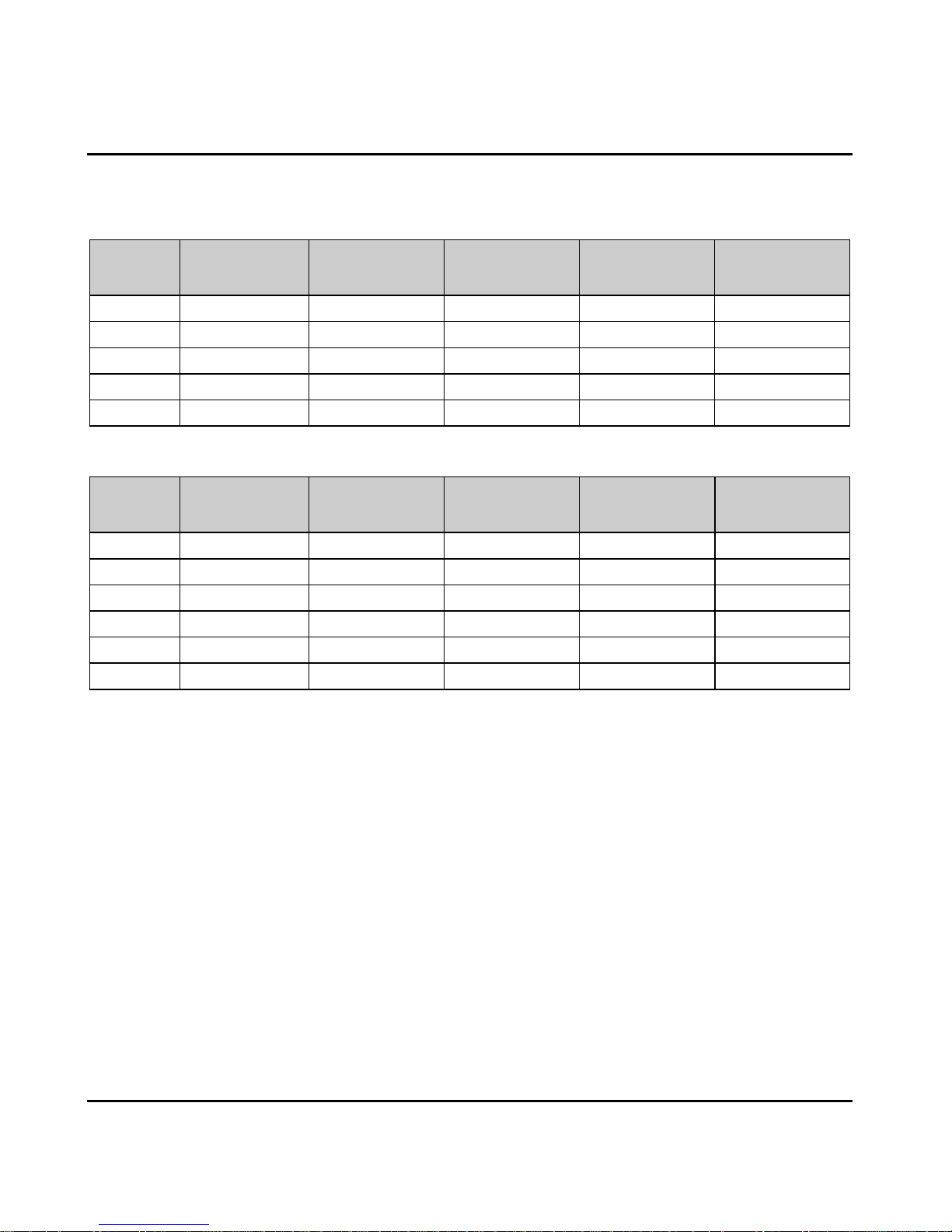
2.2 Rated Value
Single-phase: 200 - 240V, 50/60Hz
Size Model
Motor power
(kW)
Rated input
current (A)
Rated volume
(kVA)
Rated output
current (A)
Size A HD09-2S0P2G 0.25 4.3 0.6 1.7
Size A HD09-2S0P4G 0.4 5.8 1.0 2.5
Size A HD09-2S0P7G 0.75 10.5 1.5 4.0
Size A HD09-2S1P5G 1.5 18.5 2.8 7.5
Size A HD09-2S2P2G 2.2 24.1 3.8 10.0
Three-phase: 380 - 460V, 50/60Hz
Size Model
Motor power
(kW)
Rated input
current (A)
Rated volume
(kVA)
Rated output
current (A)
Size A HD09-4T0P4G 0.4 1.8 1.0 1.4
Size A HD09-4T0P7G 0.75 3.4 1.5 2.3
Size A HD09-4T1P5G 1.5 5.2 2.5 3.8
Size A HD09-4T2P2G 2.2 7.3 3.4 5.1
Size B HD09-4T4P0G 4.0 11.9 5.9 9.0
Size B HD09-4T5P5G 5.5 15.0 8.5 13.0
Page 10
Shenzhen Hpmont Technology Co., Ltd. Chapter 3 Machenical Installation
HD09 Series User Manual V1.1 -5-
Chapter 3 Machenical Installation
• After opening the package, if damage or incompleteness is found, please do not install it and
contact our distributor or us for solutions.
• When conveying the inverter, please employ suitable tools according to its weight. Please avoid
scratch to the product. Be careful: rollover and drop may cause hurt.
• Avoid scaps of the drill slip into the inverter during installation.
• For inverter with more than 2 year’s storage, please use regulator to power it slowly.
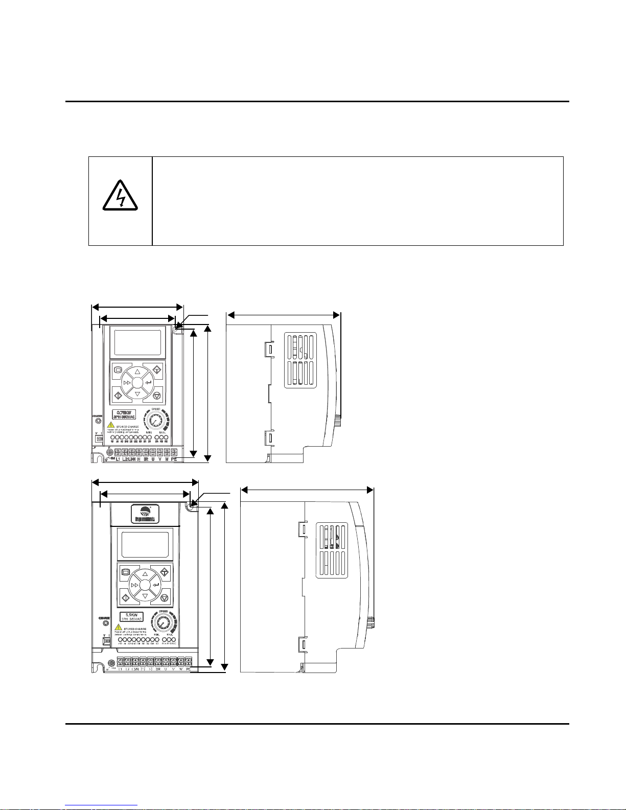
3.1 Dimension and Weight
Size A:
Dimension: 100×150×125 mm
Mounting dimension: 82×140 mm
Mounting aperture: 5 mm
G.W.: 1.5 kg
Size B:
Dimension: 116×185×145 mm
Mounting dimension: 98×174 mm
Mounting aperture: 6.5 mm
G.W.: 2.7 kg
Danger
82
1
0
0
2-Ø5
140
150
125
98
11
6
2-Ø6.5
174
185
145
Page 11
Chapter 3 Machenical Installation Shenzhen Hpmont Technology Co., Ltd.
-6- HD09 Series User Manual V1.1
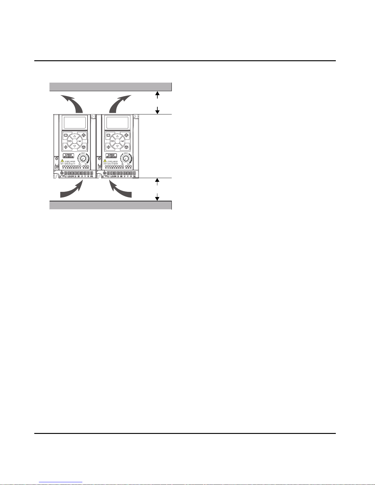
3.2 Requirement for the Installation Site
Ensure the installation site meets the following
requirements:
• Do not install at the direct sunlight, moisture,
water droplet location;
• Do not install at the flammability, explosive,
corrosive gas and liquid locations;
• Do not install at the oily dust, fiber and metal
powder location;
• Be vertical installation on fire-retardant material
with a strong support;
• Install at where the humidity is less than 95%RH
and non-condensing location;
• Install at where the vibration is 3.5m/s
2
in 2 - 9Hz, 10m/s2 in 9 - 200Hz (IEC60721-3-3);
• This inverter meets IP20, and Pollution Degree level 2 (Dry, Non conducting dust pollution);
• Make sure adequate cooling space for the inverter so as to keep the ambient temperature between
-10 - 40℃, as shown in the figure at the left;
It needs derating use if the inverter operation temperature exceeds 40℃. The derating value of the
output current of the inverter shall be 2% for each degree centigrade, Max. allowed temperature is
50℃.
≥100 mm
≥100 mm
Page 12
Shenzhen Hpmont Technology Co., Ltd. Chapter 3 Machenical Installation
HD09 Series User Manual V1.1 -7-
3.3 Installation of Exterior Keypad
HD09 allows installing the optional keypad on the keypad of control door cabinet. The optional
keypads are HD-LED-P and HD-LED-S.
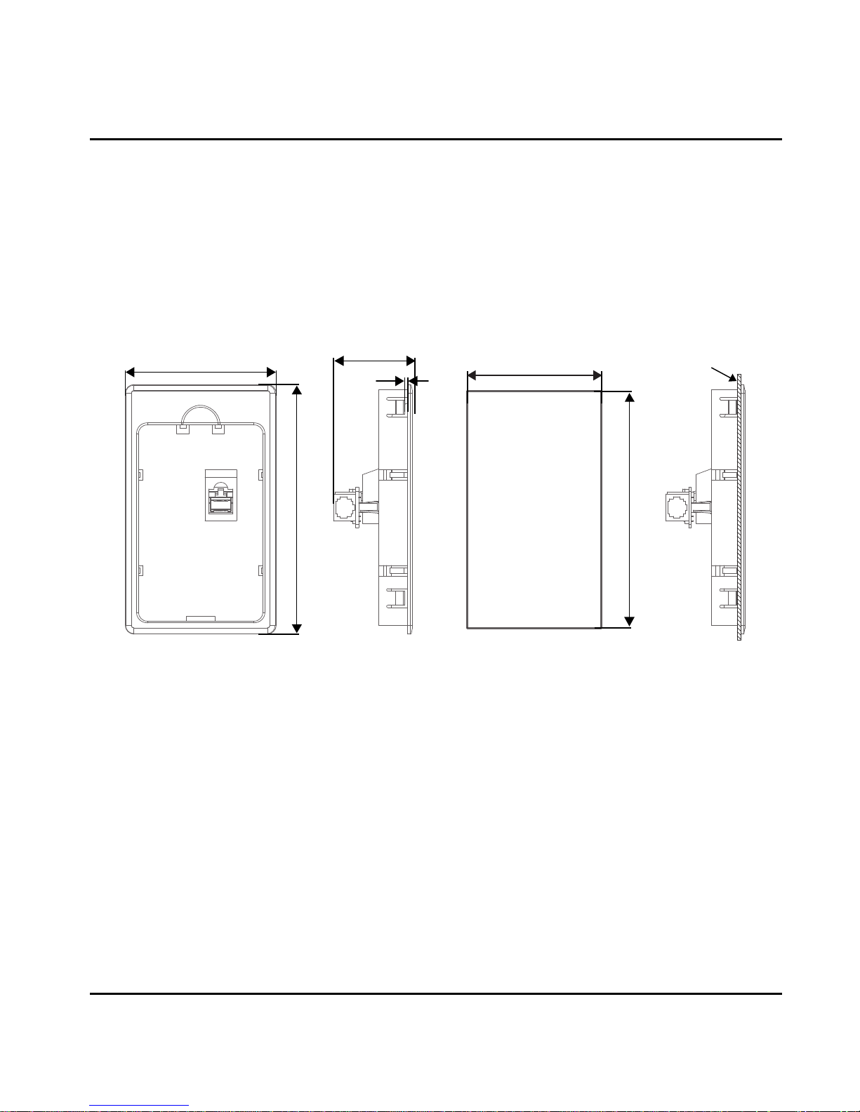
3.3.1 Installation of HD-LED-P
HD-LED-P needs a mounting base HD-KMB for installation. Firstly install the base on the keypad of
control door cabinet, and then install HD-LED-P inside the base.
The HD-KMB base and mounting aperture sizes are shown in the following figure (unit: mm).
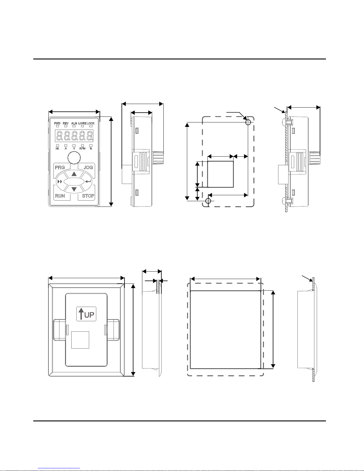
3.3.2 Installation of HD-LED-P-S
There are 2 installation methods selectable for HD-LED-P-S: install with screws or a mounting base.
Packing contents: mounting base, keypad, 2 pieces of M3x5 screws, 1 meter extension cable.
Installatio
n
Door cabinet
76.5±0.2
134.5±0.2
142
86
44.8
1.8
Mounting aperture sizeHD-KMB size
Page 13
Chapter 3 Machenical Installation Shenzhen Hpmont Technology Co., Ltd.
-8- HD09 Series User Manual V1.1
To Install with Screws
Install the HD-LED-P-S on the keypad of control door cabinet with screws.
Dimension and mounting aperture sizes are shown in the following figure (unit: mm).
To Install with a Mounting Base
Firstly install the mounting base HD-KMB-S on the keypad of control door cabinet, and then install
HD-LED-S inside the base.
The HD-KMB-S base and mounting aperture sizes are shown in the following figure (unit: mm).
HD-LED-P-S dimension Mounting aperture size
10.7 20
61
2-Ø4
31
20 11.5
25.4
70
40
16.5
32.3
Installatio
n
Door cabinet
Door cabinet
90
74
Mounting aperture size
75.5±0.2
68.5±0.2
19
1.8
Installatio
n
HD-KMB-S size
Page 14

Shenzhen Hpmont Technology Co., Ltd. Chapter 4 Electrical Installation
HD09 Series User Manual V1.1 -9-
Chapter 4 Electrical Installation
• Only qualified electrical engineer can perform wiring job.
• Only when the power supply switch is completely off can you do the wiring job.
• Check that the operation is effective and reliable after conneting to the emergency stop
terminal of external power supply.
• You must wrap the bare metal part of the power terminal with insulating tape.
• Do not touch the wire terminals of the inverter when it is live.
Ensure the power supply is completely off
Only when the power supply switch is completely off can you do the wiring job.
Steps:
First, disconnect the power supply of the inverter.
Second, wait till the internal power supply indicator goes out (its position shown in the following
figure) or wait until 5 minutes later.
Danger
Power supply indicator
Page 15

Chapter 4 Electrical Installation Shenzhen Hpmont Technology Co., Ltd.
-10- HD09 Series User Manual V1.1
4.1 Power Terminals and Connection
Power Terminal Description
Te rm in al Description
L1, L2, L3/N
Three-phase AC power input
terminals
L1, L3/N
One-phase AC power input
terminals
U, V, W
Output terminals, connect to
AC motor
(+), BR
Braking resistor connection
terminals
PE
Ground terminal, connect to
the ground
123
Te rm in al Description
L1, L2, L3/N
Three-phase AC power
input terminals
L1, L3/N
One-phase AC power
input terminals
U, V, W
Output terminals,
connect to AC motor
(+), BR
Braking resistor
connection terminals
(+), (-)
DC supply input
terminals
PE
Ground terminal,
connect to the ground
L1
Size A:
L2
L3/N
(+)BR
UVW
PE
L1 L2
L3/N
PE
WVU
BR(+) (-)
Size B:
Page 16

Shenzhen Hpmont Technology Co., Ltd. Chapter 4 Electrical Installation
HD09 Series User Manual V1.1 -11-
Power Terminal Connection
Power Terminal Wiring is as shown in following figure.
For selection of contactor, MCBB, power supply cable, motor cable, ground cable and braking resistor,
please refer to section 5.1.1 Wiring Specifications of Input and Output, page 15.
4.2 Control Terminals and Connection
Control Terminals Description
Te rm in al Description
+10 External power Max. output current100mA
AI
Analogue input
The DIP switch decides the voltage input or current input
• Voltage 0 - 10V, impedance 32kΩ (Factory setting)
• Current 0 - 20mA, impedance 500Ω
Digital input (DI
function)
When AI is used as DI, switch signals above 6V can be received
• Function F15.44 is the same with DI1 - DI3 (F15.00 - F15.02)
AO Analogue output Voltage 0 - 10V
GND Power ground Analogue and digital site, 0V
DI1, DI2, DI3 Digital input Effective with GND short circuit
L1 L2 L3/N
(+) BR
UVW
Braking resistor*
HD09
MCCB
Contactor
Supply
ground
3~
(-)
PE
M
3~
*Braking resisto is
optional three-phase
model type exclusively
+10 AI AOGND
DI1 DI2 DI3 DI4 DO
R1A R1B R1C
VI
1
ON
DIP Switch
V
I
1
ON
Page 17

Chapter 4 Electrical Installation Shenzhen Hpmont Technology Co., Ltd.
-12- HD09 Series User Manual V1.1
Te rm in al Description
DI4 Digital input
Effective with GND short circuit
or
High frequency input (F15.03 set as No. 53 function)
• Max. frequency 50.0kHz (F16.17 setting)
DO Digital output
Open collector output
• External voltage 10 - 30VDC, max. current 50mA
or
High frequency input (F15.19 set as No. 38 function)
• Max. frequency 50.0kHz (F16.26 setting)
R1A, R1B, R1C Relay output
• Contact rating: 250VAC / 3A or 30VDC / 1A
• R1B, R1C: normally closed; R1A, R1C: normally open
Note:
Limit the current within 3A if the relay terminal is to connect to AC 220V voltage signal.
Control Terminals Connection
The following figure shows wire connection of control terminal (factory setting).
+10
AI
Reference frquency: refer to F16.19
Frequency setting sources : refer to F16.01
REV function: refer to F15.00
REV function: refer to F15.01
External power: +10V, Max. output current100mA
Power ground: 0V, analogue and digital site
Unused
Inverter is running: refer to F15.19
Relay output
Inverter fault: refer to F15.20
AO
GND
DI1
DI2
DI3
DI4
DO
R1A
R1B
R1C
V
Unused
Page 18

Shenzhen Hpmont Technology Co., Ltd. Chapter 4 Electrical Installation
HD09 Series User Manual V1.1 -13-
Analogue Input Connection
Digital Input Connection
Digital Output Connection
+10
HD09
AI GND
V
I
1
ON
AI
HD09
GND
V
I
1
ON
DI1 DI2 DI3 DI4 GND
HD09 HD09
DI1 DI2 DI3 DI4 GND
External controller
Dry contact
connection
NPNconnection
10-30VDC
10kΩ
DO GND
+
-
HD09
+10 GND
DO
HD09
f
Relay coil Digital frequency
meter
Page 19

Chapter 4 Electrical Installation Shenzhen Hpmont Technology Co., Ltd.
-14- HD09 Series User Manual V1.1
4.3 External Keypad or Upper Computer
The RJ45 terminal can connect the optional keypad or upper computer, as shown in the following
figure.
RJ45
Pin Definition
1, 3 +5V
2 485+
4, 5, 6 GND
7 485-
8 Unused
Keypad
Can connect the optional keypad to realize keypad control
• Refer to Chapter 6 Keypad, page 19
Upper Computer
Can connect the upper computer to realize communication control
• The upper computer includes PLC, touch screen, PC, etc.
Connection Cable
• 1m conncection cable [HD-CAB-1M]
• 2m conncection cable [HD-CAB-2M]
• 3m conncection cable [HD-CAB-3M]
• 6m conncection cable [HD-CAB-6M]
RJ45
Connection
cable
Keypad or
upper computer
RJ45
18
Page 20

Shenzhen Hpmont Technology Co., Ltd. Chapter 5 Technical Data
HD09 Series User Manual V1.1 -15-
Chapter 5 Technical Data
5.1 Peripheral Accessories Selection
5.1.1 Wiring Specifications of Input and Output
The AC supply to the drive must be installed with suitable protection against overload and
short-circuits, i.e. MCCB (molded case circuit breaker) or equivalent device.
The recommended specification of MCCB, contactor & cables were shown as following tables.
The size of earth wire should not be smaller than the requirement in 4.3.5.4 of IEC61800-5-1.
Size Model
MCCB
(A)
Contactor
(A)
Power Cable
(mm2)
Motor Cable
(mm2)
Ground Cable
(mm2)
Size A HD09-2S0P2G 16 10 0.5 0.2 2.5
Size A HD09-2S0P4G 16 10 0.75 0.5 2.5
Size A HD09-2S0P7G 16 10 2.5 0.5 2.5
Size A HD09-2S1P5G 20 16 6.0 1.5 6.0
Size A HD09-2S2P2G 32 20 6.0 2.5 6.0
Size A HD09-4T0P4G 10 10 0.5 0.2 2.5
Size A HD09-4T0P7G 10 10 0.5 0.5 2.5
Size A HD09-4T1P5G 16 10 1.0 0.5 2.5
Size A HD09-4T2P2G 16 10 1.5 0.75 2.5
Size B HD09-4T4P0G 25 16 2.5 2.5 2.5
Size B HD09-4T5P5G 32 25 4.0 4.0 4.0
Note:
1. Please select braking resistor based on the above table.
Bigger resistor can protect the braking system in fault condition, but oversized resistor may bring a
capacity decrease, lead to over voltage protection.
2. The braking resistor should be mounted in a ventilated metal housing to prevent inadevertent contact
during it works, for the temperature is high.
Page 21

Chapter 5 Technical Data Shenzhen Hpmont Technology Co., Ltd.
-16- HD09 Series User Manual V1.1
5.1.2 Power Terminal Lug
The wiring lugs of the power terminals (round bare terminals) can be selected according to the
terminal wiring specifications, screw size, and the maximum outside diameter of the wiring lugs.
Size
Size A Size B
Screw size
M3 M3.5
Tightening torque (N. M)
0.6 - 0.8 0.8 - 1.2
Max. outer diameter of lug
d (mm)
6.1 7
5.2 Braking Resistor
Model Resistance Value (Ω) Resistance Power (W)
HD09-4T0P4G 300 - 400 80
HD09-4T0P7G 250 - 350 100
HD09-4T1P5G 200 - 300 200
HD09-4T2P2G 150 - 250 250
HD09-4T4P0G 100 - 150 300
HD09-4T5P5G 80 - 100 500
Note:
Braking unit is built in three-phase model type exclusively.
d
Page 22

Shenzhen Hpmont Technology Co., Ltd. Chapter 5 Technical Data
HD09 Series User Manual V1.1 -17-
5.3 Technical Data
Electrical
Inout voltage
HD09-2S■P■G: single-phase 200 - 240V
HD09-4T■P■G: three-phase 380 - 460V
Fluctuating within±10%, imbalance rate<3%
Input frequency 50/60Hz±5%
Output voltage 0 - input voltage
Output frequency 0 - 1000Hz
Specification
Control mode V/f
Maximum current 150% rated output current 2 minutes; 180% rated output current 10 seconds
Speed resolution
Digital setting: 0.1Hz;
Analogue setting: 0.1%×maximum frequency
Wave frequency
Default setting: 4kHz; setting range: 1 - 16kHz;
4 - 16kHz: The derating value of wave frequency shall be 2% for each more than 1kHz
Environment
Operation
temperature
-10 - +40℃, no ferating;
40 - 50℃, the derating value of the output current shall be 2% for each more than 1℃
Storage temperature -40 - +70℃
Location for use
Indoor, preveting from direct sunlight, no dust, corrosive, flammable gases, oil mist, water
vaper, dripping or salt etc.
Altitude Less than 1000m, no ferating; otherwise shouldbe serating use
Humidity Less than 95%RH, non-condensing
Vibration Resistance It is 3.5m/s2 in 2 - 9Hz, it is 10m/s2 (IEC60721-3-3) in 9 - 200Hz
Protection level IP20
Pollution degree Level 2 (Dry, Non conducting dust pollution)
Accessories
Keypad
HD-LED-P: LED keypad with potentiometer, matched with HD-KMB mounting base
HD-LED-P-S: small size keypad, matched with HD-KMB-S mounting base
Connection cable 1m / 2m / 3m / 6m connection cable [HD-CAB-1M / 2M / 3M / 6M]
Page 23

Page 24

Shenzhen Hpmont Technology Co., Ltd. Chapter 6 Keypad
HD09 Series User Manual V1.1 -19-
Chapter 6 Keypad
HD09 can either installed with LCD display keypad (standard), or LED display keypad (optional).
2 3
4 5
6
7
8 9
10
1a
1b
1c
2 3
4 5
6
6
7
7
8 9
10
10
1a
1b
1c
LCD display keypad
Standard
LED display keypad
Optional
HD-LED-P-S HD-LED-P
ENTSHF
JOGPRG
STOPRUN
Hz
AVRPM%
REVFWD ALM LO/RE LOCK
1a
1b
1c
2
3
4 5
8 9
Page 25

Chapter 6 Keypad Shenzhen Hpmont Technology Co., Ltd.
-20- HD09 Series User Manual V1.1
No. Description
1 The standard keypad contains LCD display, while the optional keypad contains LED nixie tube display.
• Three status: lighting, flashing and lightless.
• Do not remove the standard LCD keypad.
a. Status indicator: indicating current status.
• FWD (Forward status): Motor is forward running (standard LCD) / lighting (optional LED)
• REV (Reverse status): Motor is reverse running (standard LCD) / lighting (optional LED)
• ALM (Alarm status): Motor is faulty (standard LCD) / lighting (optional LED)
• LO/RE(Local/Remote status): Inverter is in terminal or communication control mode (standard LCD) /
lighting (optional LED)
• LOCK (Password locked status): User password lock of the inverter is avail (standard LCD) / lighting
(optional LED)
b. Display area: Normal: displays parameter. Faulty: displays error code when the inverter is faulty.
• If a value is flashing, it mean that the value is revisable.
c. Unit indicator: Display unit of the current value.
• Include: Hz (frequency), A (current), V (voltage), RPM (rotate speed), % (percentage)
2
Program/Exit button: Entry or programming button
3
Jog button: In the keypad control, jog start the inverter
4
Run button: In the keypad control, press this button to run the inverter
5
Stop/Reset button: In the keypad control, to stop the inverter and reset the fault
6
Increment button: In selecting parameter status, press it to increass the value of
parameter; In setting parameter status, press it to incress the setting value.
7
Decrement button: In selecting parameter status, press it to decreass the value of
parameter; In setting parameter status, press it to decress the setting value.
8
SHE shift button: In selecting pr setting parameter status, shift 1 bit.
9
ENT enter/confirm button: Enter lower menu; In setting parameter status, confirm and
save the data.
10
Potentiometer: In setting parameter status, anti-clockwise means decrease, while clockwise means
increase.
Page 26

Shenzhen Hpmont Technology Co., Ltd. Chapter 7 Troubleshooting
HD09 Series User Manual V1.1 -21-
Chapter 7 Troubleshooting
HD09 series inverter has inbuilt protective and warning self-diagnostic functions. If a fault occurs, the
fault code will be displayed on the display keypad. At the same time, fault relay acts, accordingly the
inverter stops output and the motor coasts to stop.
When fault or alarm occurs, please record the fault details and take proper actions according to the
below table. If you need some technical help, please contact to the suppliers or directly call Shenzhen
Hpmont Technology Co., Ltd..
After the fault is eliminated, please reset the inverter by any of the following methods:
1. Display keypad. Press (standard) / (optional).
2. External reset terminal (multi-function terminal set as No. 46 function).
3. Communication.
4. Switching on the inverter after switching off.
Fault Fault reasons Counter-measures
-Lu- DC bus undervoltage
• At the begining of powering on
and at the end of powering off
• Input voltage is too low
• Improper wiring leads to
undervoltage of hardware
• It is normal status of powering on
and powering off
• Please check input power voltage
• Please check wiring and wire the
inverter properly
E0001
Inverter acceleration
overcurrent
• Improper connection between
inverter and motor
• Improper motor parameters
• The rating of the used inverter is
too small
• Acceleration/deceleration time is
too short
• Connect the inverter and motor
properly
• Please set correct motor parameters
(F08.00 - F08.03)
• Select inverter with higher rating
Please set proper acceleration time
and deceleration time (F03.01,
F03.02)
E0002
Inverter deceleration
overcurrent
E0003
Inverter constant
speed overcurrent
E0004
DC bus acceleration
over voltage
• Input voltage is too high
• Deceleartion time is too short
• Improper wiring leads to
overvoltage of hardware
• Improper selection of the
braking devices
• Please check power input
• Please set a proper value for
deceleration time (F03.02)
• Please check wiring and wire the
inverter properly
• Select according to the
recommended braking devices of
section 5.2 Braking Resistor, page 16
E0005
DC bus deceleration
over voltage
E0006
DC bus constant
speed over voltage
Page 27

Chapter 7 Troubleshooting Shenzhen Hpmont Technology Co., Ltd.
-22- HD09 Series User Manual V1.1
Fault Fault reasons Counter-measures
E0007 Stall overvoltage
• Bus voltage is too high
• The setting of stall overvoltage is
too low
• Please check power input or the
function of brake
• Set the value of stall overvoltage
properly (F19.19)
E0008
Fault of power
module
• Short circuit between phases
output
• Short circuit to the ground
• Output current is too high
• Power module is damaged
• Please check the connection and
connect the wire properly
• Please check the connection and
connect the wire properly
• Please check the connection and
mechanism
• Please contact the supplier for
repairing
E0009 Heatsink overheat
• Ambient temperature is too high
• Inverter external ventilation is
not good
• Fan fault
• Fault occurs to temperature
detection circuit
• Please use inverter with higher
power capacity
• Improve the ventilation around the
inverter
• Replace the cooling fan
• Please seek technical support
E0011 CPU fault • CPU abnormal
• Please detect at power on after
completely power outage
• Please seek technical support
E0012
Parameters
auto-tuning fault
• Parameter auto-tuning is time
out
• Please check the motor’s connection
• Input the correct motor parameters
(F08.01 - F08.03)
• Please seek technical support
E0013
Contactor is not
actuated
• Contactor fault
• Fault of control circuit
• Replace the contactor
• Please seek technical support
E0014
Fault of current
detection circuit
• Current detection circuit is
damaged
• Please contact the supplier for
repairing
E0016 Fault of output phase
• Output phase disconnection or
loss
• Heavy imbalance of inverter’s
three-phase load
• Please check the connection
between inverter and motor
• Please check the quality of motor
E0017 Inverter overload
• Acceleration time is too short
• Improper setting of V/f curve or
torque boost leads to over
current
• Mains supply voltage is too low
• Motor load is too high
• Adjust acceleration time (F03.01)
• Adjust V/f curve (F09.01 - F09.06) or
torque boost (F09.07, F09.08)
• Please check mains supply voltage
• Please use inverter with proper
power rating
Page 28

Shenzhen Hpmont Technology Co., Ltd. Chapter 7 Troubleshooting
HD09 Series User Manual V1.1 -23-
Fault Fault reasons Counter-measures
E0019 Motor overload
• Improper setting of V/f curve
• Mains supply voltage is too low
• Normal motor runs for a long
time with heavy load at low
speed
• Motor runs with blocked torque
or load is too heavy
• Adjust the setting of V/f curve
(F09.01 - F09.06)
• Check the power input
• Please use special motor
• Please check the load and
mechanical transmission devices
E0021
Access fault of
Control board
EEPROM
• Memory circuit fault of control
board EEPROM
• Please contact the supplier for
repairing
E0024
Fault of external
equipment
• Fault terminal of external
equipment operates
• Please check external equipment
E0028
SCI communication
time-out
• Connection fault of
Communication cable
• Disconnected or not well
connected
• Please check the connection
E0029
SCI communication
error
• Connection fault of
Communication cable
• Disconnected or not well
connected
• Communication setting error
• Communication data error
• Please check the connection
• Please check the connection
• Please correctly set the
communication format (F17.00), and
the baud rate (F17.01)
Note:
If E0028 or E0029 are displayed on the keypad, there is no need to stop the inverter.
Page 29

Page 30

Shenzhen Hpmont Technology Co., Ltd. Chapter 8 Parameter
HD09 Series User Manual V1.1 -25-
Chapter 8 Parameter
Attributes are changed:
“X”: It denotes that the setting of this parameter cannot be modified when the inverter is in run
status.
“O”: It denotes that the setting of this parameter can be modified when the inverter is in run status.
“*”: It denotes that the value of this parameter is the actual value which cannot be modified.
Ref. Code Function Setting Range Default Unit Attribute Setting
F00: Basic Parameter
F00.06
Inverter max. output
frequency
50.0 - 1000.0Hz 50.0Hz 0.1Hz ×
F00.08
Upper limit of operation
frequency
0.0 - F00.06 50.0Hz 0.1Hz ×
F00.09
Lower limit of operation
frequency
0.0 - F00.08 0.0Hz 0.1Hz ×
F00.10
Frequency setting
sources selection
0: Keypad digital setting
1: Terminal digital setting
2: SCI communication setting
3: AI analogue setting
4: Terminal pulse setting
0 1 ×
F00.11
Command setting
source selection
0: Keypad running source
1: Terminal running source
2: SCI communication running source
0 1 ×
F00.13
Starting frequency digital
setting
0.0 - F00.08 50.0Hz 0.1Hz ○
F00.14
UP/DOWN digital setting
control
Units: Frequency setting save selection
at power outage
0: Not save in power off
1: Save in power off
Tens: Frequency setting control
selection at stop
0: Set frequency keeping in stop
1: Rcovery frequency to F00.13 in stop
Hundreds: Communication setting
frequency storage selection
1001 1 ×
Page 31

Chapter 8 Parameter Shenzhen Hpmont Technology Co., Ltd.
-26- HD09 Series User Manual V1.1
Ref. Code Function Setting Range Default Unit Attribute Setting
0: Not save in power off
1: Save in power off
Thousands: Switch the frequency
channel to the analogue selection
0: Not save
1: Save
F00.15
Jog operation frequency
digital setting
0.0 – up limitation (F00.08) 5.0Hz 0.1Hz ○
F00.17
Running direction
selection
0: Same direction
1: Reserved direction
0 1 ×
F00.19
Dead time of direction
switch
0.0 - 3600.0s 0.0s 0.1s ×
F00.20 Keypad enbale
Unit: Button enbale
0: Enable
1: Disable
Ten: Potentiometer enbale
0: Potentiometer priority for keypad
1: Potentiometer with keypad
2: Potentiometer with external keypad
00 1 ○
F00.21 Sleep function enbale
0: Disable
1: Enable 1
2: Enable 2
0 1 ×
F00.22 Dormant wake time 0.0 - 360.0s 0.0s 0.1s ×
F00.24 Sleep delay 0.0 - 3600.0s 0.0s 0.1s ×
F00.25 Sleep frequency 0.0Hz - F00.08 0.5Hz 0.1Hz ○
F01: Protection of Parameters
F01.00 User’s password 00000 - 65535 00000 1 ○
F01.01 Menu mode selection
0: Full menu mode
1: Checking menu mode
0 1 ○
F01.02
Function code parameter
initialization (parameter
download)
0: No operation
1: Restore to factory settings
2/3: keypad stored parameter 1/2
iscopied to control board and update
current function value
4: Clear fault information
0 1 ×
F01.03
Copy parameter to keypad
0: No operation 0 1 ○
Page 32

Shenzhen Hpmont Technology Co., Ltd. Chapter 8 Parameter
HD09 Series User Manual V1.1 -27-
Ref. Code Function Setting Range Default Unit Attribute Setting
(parameter uploading)
1/2: Current function values are copied
to keypad stored parameter 1/2
F02: Run / Stop Control Parameters
F02.02
Start DWELL frequency
setting
0.0 - F00.08 0.0Hz 0.1Hz ×
F02.03
Retention time of starting
DWELL frequency
0.00 - 10.00s 0.00s 0.01s ×
F02.04 DC braking current setting 0 - 100% 50% 1% ×
F02.05 DC braking time at start 0.00 - 60.00s 0.00s 0.01s ×
F02.13 Stop mode selection
1: Coast to stop
2: Decelerate to stop
2 1 ×
F02.14
DWELL frequency setting
at stop
0.0 - F00.08 0.0Hz 0.1Hz ×
F02.15
Retention time of DWELL
frequency at stop
0.00 - 10.00s 0.00s 0.01s ×
F02.16
DC braking initial
frequency at stop
0.0 - 50.0Hz 0.5Hz 0.1Hz ×
F02.18 DC braking time at stop 0.00 - 60.00s 0.00s 0.01s ×
F03: Acceleration/Deceleration Parameters
F03.01 Acceleration time 1 0.01 - 600.00s 10.00s 0.01s ○
F03.02 Deceleration time 1 0.01 - 600.00s 10.00s 0.01s ○
F03.03 Acceleration time 2 0.01 - 600.00s 10.00s 0.01s ○
F03.04 Deceleration time 2 0.01 - 600.00s 10.00s 0.01s ○
F03.05 Acceleration time 3 0.01 - 600.00s 10.00s 0.01s ○
F03.06 Deceleration time 3 0.01 - 600.00s 10.00s 0.01s ○
F03.07 Acceleration time 4 0.01 - 600.00s 10.00s 0.01s ○
F03.08 Deceleration time 4 0.01 - 600.00s 10.00s 0.01s ○
F03.09
Ace. time 2 and 1 switch
frequency
0.0 - up limitation 0.0Hz 0.0Hz ×
F03.10
Dec. time 2 and 1 switch
frequency
0.0 - up limitation 0.0Hz 0.0Hz ×
F03.15 Spot Ace. time 0.01 - 600.00s 6.00s 0.01s ○
F03.16 Spot Dec. time 0.01 - 600.00s 6.00s 0.01s ○
F04: Process PID Control
F04.00
Process PID control
selection
0: PID control is disabled
1: PID control is enabled
0 1 ×
Page 33

Chapter 8 Parameter Shenzhen Hpmont Technology Co., Ltd.
-28- HD09 Series User Manual V1.1
Ref. Code Function Setting Range Default Unit Attribute Setting
F04.02 Feedback source selection
0: AI analogue feedback
1: Terminal pulse feedback
0 1 ×
F04.03 Setting digital reference 0.0 - 100.0% 0.0% 0.1% ○
F04.04 Proportional gain (P) 0.00 - 10.00 2.00 0.01 ○
F04.05 Integral time (I) 0.01 - 10.00s 1.00s 0.01s ○
F04.07 Differential time (D) 0.00 - 10.00s 0.00s 0.01s ○
F04.08
Differential amplitude limit
value
0.0 - F00.08 20.0Hz 0.1Hz ○
F04.09 Sampling cycle (T) 0.01 - 50.00s 0.10s 0.01s ○
F04.10 Bias limit 0.0 - 20.0% 2.0% 0.1% ○
F04.16
Integral regulation
selection
0: Stop integral regulation when the
frequency reaches the upper or lower
limit
1: Continue the integral regulation
when the frequency reaches the upper
or lower limit
0 1 ×
F04.17 PID output filter time 0.01 - 10.00s 0.05s 0.01s ○
F04.18
PID output reverse
selection
0: PID regulation disable reverse
(When PID output is negative, 0 is the
limit)
1: PID regulation enable reverse
0 1 ×
F04.19
PID output reverse
frequency’s upper limit
0.0 - F00.08 50.0Hz 0.1Hz ×
F05: External Reference Curve Parameters
F05.01 Minimum reference of line 0.0% - F05.03 0.0% 0.1% ○
F05.02
Minimum reference
corresponding value of
line
0.0 - 100.0% 0.0% 0.1% ○
F05.03 Maximum reference of line F05.01 - 100.0% 100.0% 0.1% ○
F05.04
Maximum reference
corresponding value of
line
0.0 - 100.0% 100.0% 0.1% ○
F05.17 Skip frequency F00.09 - F00.08 0.0Hz 0.1Hz ×
F05.20 Range of skip frequency 0.0 - 30.0Hz 0.0Hz 0.1Hz ×
F06: Multi-step Speed Parameters
F06.00
Multi-step frequency
Command 1
F00.09 - F00.08 5.0Hz 0.1Hz ○
Page 34

Shenzhen Hpmont Technology Co., Ltd. Chapter 8 Parameter
HD09 Series User Manual V1.1 -29-
Ref. Code Function Setting Range Default Unit Attribute Setting
F06.01
Multi-step frequency
Command 2
F00.09 - F00.08 5.0Hz 0.1Hz ○
F06.02
Multi-step frequency
Command 3
F00.09 - F00.08 5.0Hz 0.1Hz ○
F06.03
Multi-step frequency
Command 4
F00.09 - F00.08 5.0Hz 0.1Hz ○
F06.04
Multi-step frequency
Command 5
F00.09 - F00.08 5.0Hz 0.1Hz ○
F06.05
Multi-step frequency
Command 6
F00.09 - F00.08 5.0Hz 0.1Hz ○
F06.06
Multi-step frequency
Command 7
F00.09 - F00.08 5.0Hz 0.1Hz ○
F08: Motor Parameters
F08.00 Rated power of motor 0.2 - 5.5kW
Depende
nt on
HD09
0.1kW ×
F08.01 Rated voltage of motor 0V - inverter’s rated voltage 1V ×
F08.02 Rated current of motor 0.01 - 99.99A 0.01A ×
F08.03 Rated frequency of motor 1 - 1000Hz 50Hz 1Hz ×
F08.04 Rated Rpm of motor 1 - 24000rpm
Depende
nt on
HD09
1rpm ×
F08.06
Parameter auto-tuning of
motor
0: Auto-tuning is disabled
1: Stationary auto-tuning
0 1 ×
F08.07 Stator resistance of motor 0.00 - 99.99Ω
Depende
nt on
HD09
0.01Ω ×
F09: V/f Control Parameters
F09.01 V/f frequency value F3 F09.03 - 100.0% (F08.03) 100.0% 0.1% ×
F09.02 V/f voltage value V3 F09.04 - 100.0% (F08.01) 100.0% 0.1% ×
F09.03 V/f frequency value F2 F09.05 - F09.01 (F08.03) 0.0% 0.1% ×
F09.04 V/f voltage value V2 F09.06 - F09.02 (F08.01) 0.0% 0.1% ×
F09.05 V/f frequency value F1 0.0% - F09.03 (F08.03) 0.0% 0.1% ×
F09.06 V/f voltage value V1 0.0% - F09.04 (F08.01) 0.0% 0.1% ×
F09.07 Torque boost 0.0 - 30.0% 2.0% 0.1% ×
F09.08
Cut-off point used for
manual torque boost
0.0 - 50.0% (F08.03) 30.0% 0.1% ○
F09.09
Motor transfer
compensation gain
0.0 - 300.0% 0.0% 0.1% ○
Page 35

Chapter 8 Parameter Shenzhen Hpmont Technology Co., Ltd.
-30- HD09 Series User Manual V1.1
Ref. Code Function Setting Range Default Unit Attribute Setting
F09.10
Compensation filtering
time for motor transfer
0.01 - 10.00s 0.10s 0.01s ○
F09.11
Differential compensation
for motor differential
0.0 - 250.0% 200.0% 0.1% ×
F09.12
The time constant of the
motor compensation
0.1 - 25.0s 2.0s 0.1s ○
F09.14
AVR (automatic voltage
regulation) function
0: No action
1: Keep acting
2: No action only in Dec.
1 1 ○
F09.15
Oscillation-suppression
mode
0: Oscillation-suppression mode 1
1: Oscillation-suppression mode 2
0 1 ○
F09.16
Oscillation-suppression
coefficient
0 - 200 50 1 ○
F15: Digital Input/Output Terminal Parameters
F15.00 DI1 function
0: Unused
1: Inverter enabled
2,3: FWD / REV function
4: Three-wire operation mode
8: AI to be the frequency source
11: Terminal control mode to be the
run command source
13 - 15: Multi-step frequency terminal
1 - 3
17: Frequency ramp (UP)
18: Frequency ramp (DN)
19: Clearing auxiliary frequency setting
20,21: Forward and reverse jog
command control input (JOGF / JOGR)
26,27: Selection terminals in Ace. and
Dec. time 1,2
41: Coast to stop (normally-open
input)
42: Coast to stop (normally-closed
input)
44: External fault signal (normally-open
input)
45: External fault signal (normallyclosed input)
46: External reset input (RST)
2 1 ×
F15.01 DI2 function 3 1 ×
F15.02 DI3 function 0 1 ×
F15.03 DI4 function 0 1 ×
Page 36

Shenzhen Hpmont Technology Co., Ltd. Chapter 8 Parameter
HD09 Series User Manual V1.1 -31-
Ref. Code Function Setting Range Default Unit Attribute Setting
F15.44
AI terminal (ADI function)
selection
50: Clearing the counter to zero
51: Counter’s triggering signal input
53: Pulse frequency input (only DI4
terminal is enabled)
ADI is valid when F15.44 is not as . as 0,
only AI is valid.
0 1 ×
F15.12
Acc / Dec rate of UP/DN
terminal
0.0 - 99.9Hz/s 1.0Hz/s 0.1Hz/s ×
F15.14
Terminal detecting filter
number
0 - 10000 2 1 ○
F15.15
Terminal input positive
and negative logic setting
Bit0 - Bit3 is corresponding to DI1 - DI4
Bit12 is corresponding to AI
Bitx: DIy terminal input positive and
negative logic
0: Positive logic
1: Negative logic
0 1 ○
F15.16
FWD / REV operation
mode
0: Two-wire operation mode 1
1: Two-wire operation mode 2
2: Three-wire operation mode 1
3: Three-wire operation mode 2
0 1 ×
F15.19 DO function
0: Unused
2: Inverter is running (RUN)
3: Inverter is forward running
4: Inverter is reverse running
5: Inverter is DC braking
9: Frequency detection threshold (FDT)
11: Frequency arriving signal (FAR)
20: Output data from SCI
communication
21: Preset operating time out
23: Preset counting value reach
24: Indicating counting value reach
31: Inverter fault
38: High-frequency output (only DO)
2 1 ×
F15.20 Relay function 31 1 ×
F15.27 FAR range 0.0 - 100.0Hz 2.5Hz 0.1Hz ○
F15.31 FDT level 0.0 - F00.06 50.0Hz 0.1Hz ○
F15.32 FDT lag - F00.06 - F00.06 1.0Hz 0.1Hz ○
F15.36 Preset operating time 0 - 65535h 0h 1h ○
Page 37

Chapter 8 Parameter Shenzhen Hpmont Technology Co., Ltd.
-32- HD09 Series User Manual V1.1
Ref. Code Function Setting Range Default Unit Attribute Setting
0: Preset operating time is disabled
F15.37
Preset counting value
arriving
F15.38 - 9999 0 1 ○
F15.38
Specified counting value
arriving
0 - F15.37 0 1 ○
F15.43 Terminal output delay 0.0 - 100.0s 0.0s 0.1s ×
F16: Analogue I/O Terminal Parameters
F16.00
Keypad with
potentiometer function
0: Unused
2: Frequency setting source
3: Auxiliary frequency reference
5: Process PID feedback
0 1 ×
F16.01 AI function 2 1 ×
F16.05 AI bias -100.0 - 100.0% 0.0% 0.1% ○
F16.06 AI gain 0.00 - 10.00 1.00 0.01 ○
F16.07 AI input filtering time 0.01 - 10.00s 0.05s 0.01s ○
F16.17
DI4 max. input pulse
frequency
0.0 - 50.0kHz 10.0kHz 0.1kHz ○
F16.18
DI4 input pulse filtering
time
0 - 500ms 10ms 1ms ○
F16.19 AO function
0: Unused
2: Reference frquency (0 - max. output
frequency)
3: Motor speed (0 - max. output
frequency corresponding to speed)
5: Output current (0 - twice motor’s
rated current)
11: Output voltage (0 - 1.2 times
inverter’s rated voltage)
12: Bus voltage (0 - 2.2 times inverter’s
rated voltage)
2 1 ○
F16.21 DO function 0 1 ○
F16.22 AO bias -100.0 - 100.0% 0.0% 0.1% ○
F16.23 AO gain 0.0 - 200.0% 100.0% 0.1% ○
F16.26
DO max. output pulse
frequency
0.1 - 50.0kHz 10.0kHz 0.1kHz ○
F17: SCI Communication Parameters
F17.00 Data format
0: 1-8-2 format, no parity, RTU
1: 1-8-1 format, even parity, RTU
2: 1-8-1 format, odd parity, RTU
0 1 ×
F17.01 Baud rate selection 0: 1200bps 3 1 ×
Page 38

Shenzhen Hpmont Technology Co., Ltd. Chapter 8 Parameter
HD09 Series User Manual V1.1 -33-
Ref. Code Function Setting Range Default Unit Attribute Setting
1: 2400bps
2: 4800bps
3: 9600bps
4: 19200bps
5: 38400bps
F17.02 Local address 0 - 247 2 1 ×
F17.03 Host PC response time 0 - 1000ms 1ms 1ms ×
F17.04
Time threshold for
detecting communication
status
0.0 - 1000.0ms
0.0: Not detecting communicaiton over
time
0.0s 0.1s ×
F17.05
Detecting time at
communication error
0.0 - 1000.0ms
0.0: Not detecting communicaiton error
0.0s 0.1s ×
F17.09
Communication write
function parameter of
storage EEPROM method
selection
Units: Communication write function
parameter of storage EEPROM method
selection (Except for F00.13 and
F19.03)
Tens: Communication write function
parameter of storage EEPROM method
selection for F00.13 and F19.03
0: Without storage EEPROM
1: Storage EEPROM
01 1 ×
F17.10
Detecting time when
network communication
over time
0.0 - 600.0s
0.0: Not detecting communicaiton error
0.0s 0.1s ×
F18: Display Control Parameter
F18.02
Running display
parameter 1 setting
0: Reserved
1: Inverter rated current
3: Inverter status
4: Main setting frequency channel
5: Main setting frequency
7: Setting frequency
8: Given frequency (after Dec. and Ace.)
9: Output frequency
10: Setting RPM
11: Running rpm
13: Output voltage
14: Output current
8 1 ○
Page 39

Chapter 8 Parameter Shenzhen Hpmont Technology Co., Ltd.
-34- HD09 Series User Manual V1.1
Ref. Code Function Setting Range Default Unit Attribute Setting
F18.08
Stop display parameter 1
setting
15: Torque given
16: Output torque
17: Output power
18: DC bus voltage
19: Keypad potentiometer input
voltage
20: AI input voltage
21: AI input voltage (after handling)
28: DI4 terminal pulse input frequency
29: AOoutput
32: Heat sink temperature
33: Given line speed
34: Given line speed
42: External value
43: Input terminals statues
44: Output terminals status
48: Total power time accumulates
(hours)
49: Total running time accumulates
(hours)
7 1 ○
F18.14 Frequency display gain 0.1 - 160.0 1.0 0.1 ○
F18.15 Max. line speed 0 - 65535 1000 1 ○
F18.16
Line speed display
accuracy
0: Integer
1: A decimal
2: Two decimals
3: Three decimals
0 1 ×
F18.17
LCD Backlighting screen
saver mode
0: Current mode
1: External signal input changed,
cancenl backlighting screen
0 1 ○
F19: Function-boost Parameters
F19.07
Control selection of
cooling fan
0: Auto stop mode
1: Immediate stop mode
2: The fan runs continuously when
power on
0 1 ×
F19.08
Cooling fan controls
delaying time
0.0 - 600.0s 30.0s 0.1s ×
F19.12
Instantaneous loss of
power and no stop
function selection
0: Disable instantaneous loss and no
stop
1: Enbale instantaneous loss and no
0 1 ×
Page 40

Shenzhen Hpmont Technology Co., Ltd. Chapter 8 Parameter
HD09 Series User Manual V1.1 -35-
Ref. Code Function Setting Range Default Unit Attribute Setting
stop
F19.13
Instant stop function
deceleration time
0.01 - 600.00s 5.00s 0.01s ○
F19.14
Voltage rerise judgement
time for Instantaneous loss
of power and no
downtime
0.00 - 10.00s 0.10s 0.01s ○
F19.15
Voltage judgement for
Instantaneous loss of
power and no downtime
0 - 999V
220V
inverter:
248V
380V
inverter:
430V
1V ×
F19.18
Protection of stall
overvoltage
0: Disabled (with braking resistance)
1: Enabled
1 1 ×
F19.19 Stall overvoltage point 0 - 999V
Depende
nt on
HD09
1V ×
F19.20
Auto current limiting
selection
0: Disabled
1: Enabled in Acc / Dec running
process, but disabled in constant
speed runnng process
2: Enabled both in Acc / Dec and in
constant speed running proces
1 1 ×
F19.21
Auto current limiting
threshold
20.0 - 200.0% 150.0% 0.1% ×
F19.22
Deceleration time at auto
current limiting
0.00 - 600.00s 0.00s 0.01s ×
F19.23
Enabled mode of terminal
run command
0: Rise edge enabled mode
1: Level enabled mode
0 1 ○
F19.24
Action voltage of braking
unit
630 - 750V
Depende
nt on
HD09
1V ×
F19.37
Frequency adjust range
selection
Unit: Main frequency range
0: 0 - max. frequency
1: Negative maximum frequency to
maximum frequency
100 1 ○
Page 41

Chapter 8 Parameter Shenzhen Hpmont Technology Co., Ltd.
-36- HD09 Series User Manual V1.1
Ref. Code Function Setting Range Default Unit Attribute Setting
Ten : U n u s e d
Hundreds: The range of synthetic
frequencies
0: 0 - up limitation frequency
1: Negative upper limit frequency to
upper limit frequency
F19.39 Input voltage selection
Unit : 380V input voltage
0: 380 - 460V
1: 260 - 460V
2: 200 - 460V
Ten: 220V input voltage selection
0: 200 - 240V
1: 140 - 240V
00 1 ×
F19.44 LCD Backlight display time 0.0 - 999.9min 5.0min 0.1min ○
F20: Protection of Fault Parameters
F20.00
Selection for overload
prediction police check
out
00000: Enbale overload protection
10000: Disbale overload protection
00000 1 ○
F20.10
Output phase loss
detection reference
0 - 50% 20% 1% ×
F20.11
Output phase loss
detection time
0.00 - 20.00s 3.00s 0.01s ×
F20.18 Auto reset times 0 - 100 0 1 ×
F20.19 Auto reset interval 2.0 - 20.0s/times
5.0
s/times
0.1
s/times
×
F20.21
Type of third latest (the
last) fault
-Lu-: DC bus undervoltage
E0001: Acc overcurrent
E0002: Dec overcurrent
E0003: Costant overcurrent
E0004: Acc overvoltage
E0005: Dec overvoltage
E0006: Constant overvoltage
E0007: Stall overvoltage
E0008: Fault of power module
E0009: Heatsink overheat
E0011: CPUfault
E0012: Parameters auto-tuning fault
E0013: Contactor is not actuated
0 1 *
Page 42

Shenzhen Hpmont Technology Co., Ltd. Chapter 8 Parameter
HD09 Series User Manual V1.1 -37-
Ref. Code Function Setting Range Default Unit Attribute Setting
E0014: Fault of current detection circuit
E0016: Fault of output phase
E0017: Inverter overload
E0019: Motor overload
E0021: Access fault of control board
EEPROM
E0024: Fault of external equipment
E0028: SCI communication time-out
E0029: SCI communication error
F20.22
Setting frequency at the
last fault
0.0 - 1000.0Hz 0.0Hz 0.1Hz *
F20.23
Running frequency at the
last fault
0.0 - 1000.0Hz 0.0Hz 0.1Hz *
F20.24 Bus voltage at the last fault 0 - 999V 0V 1V *
F20.25
Output voltage at the last
fault
0 - 999V 0V 1V *
F20.26
Output current at the last
fault
0.00 - 99.99A 0.00A 0.01A *
F20.29 Interval of third latest fault 0.0 - 6553.5h 0.0h 0.1h *
F20.30 Type of second latest fault 0 - 99 0 1 *
F20.31
Interval of second latest
fault
0.0 - 6553.5h 0.0h 0.1h *
F20.32 Type of first latest fault 0 - 99 0 1 *
F20.33 Interval of first latest fault 0.0 - 6553.5h 0.0h 0.1h *
F23: PWM Control Parameters
F23.00 Set the carrier frequency 1 - 16kHz 4kHz 1kHz ×
 Loading...