

Instruction Manual
Forta LED Floodlight with Sensor
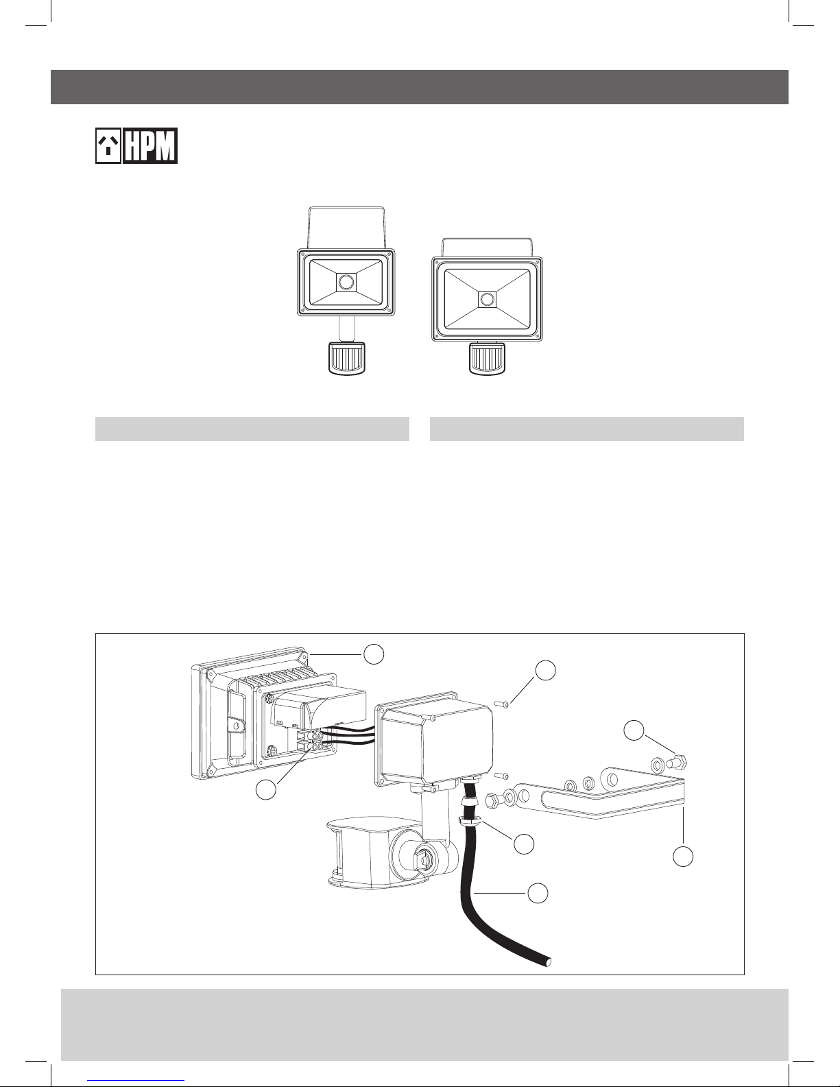
Cat. No. LFS0110WBL, LFS0130WBL
Fig. 2
Introduction
This floodlight incorporates an automatic passive infrared (PIR) sensor.
The sensor continuously scans a preset operating zone and immediately
switches the floodlight ON when it detects movement from people and
animals. It can be used to illuminate pathways, steps, patios, porches
or other areas that require lighting for reasons of safety, convenience or
security. Whilst there is movement within the scanning area the floodlight
will remain on.
Where to fit your floodlight
Before selecting a place to install your floodlight you should note that
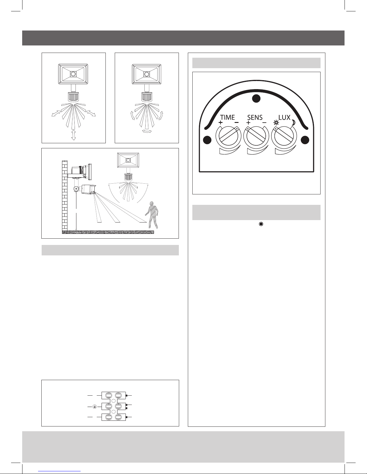
movement across the scan area is more effective than movement directly
toward or away from the sensor (refer FIG. 1B). If movement is made
walking directly towards or away from the sensor and not across, the
apparent detection range will be substantially reduced (refer FIG. 1A).
Always mount the floodlight in a sheltered position, i.e. under the eaves
of the house.
Do not operate in close proximity to combustible materials or substances
affected by heating or drying. Keep a minimum distance of 0.5m from
adjacent objects.
Ideally the floodlight should be mounted more than 2m above the area to
be scanned (refer to Fig. 3).
This product must be installed by a licensed electrician.
1 Lamp Cover Screw
2 Terminal Block
3 Junction Box Cover Screws (x 4pcs)
4 Wall Mounting Bracket Screws (x 2pcs)
5 Wall Mounting Bracket
6 Gland
7 Power Cable (not provided)
1
2
3
4
5
7
6
White wire to lightBlue wire to neutral N
White wire to light
Green-yellow to light
Green-yellow to earth
Brown wire to switch L
Setting the controls
With floodlight fully installed by electrician and
power on
1. Turn the LUX control knob to light ( ) position, turn the wall switch
on and wait 30 seconds for the control circuit to stabilise. Ensure the
TIME control knob is set at minimum (-).The lamp on the sensor light
will now switch on and will remain on for about 10sec.
2. Direct the sensor toward the desired scanning area by adjusting
the elbow joint and swivel joint on the sensor arm. Important:
loosen all lock nuts and screws on sensor arm and wall mount
bracket before making any adjustments.
3. Have someone move across the centre of the area to be scanned and
slowly adjust the angle of the sensor arm until the unit senses the
moving person, causing the lamp to switch on. (Refer Fig.1 B)
4. Adjust time control to required setting.
5. To set the light level at which the lamp will automatically switch
“On”, turn the LUX control knob from daylight to night. If the lamp
is required to switch on earlier, e.g. dusk, wait for the desired light
level, then slowly turn the LUX control knob towards daylight while
someone walks across the centre of the area to be detected. When
the lamp switches on, release the LUX knob. You may need to
make further adjustments to achieve your ideal light level setting.
Important: To avoid dust build-up and ensure proper functioning
of the sensor light, wipe the sensor lens lightly with a damp
cloth every 3 months. Never modify the unit, there are no user
serviceable parts inside.
Dial settings show
TEST MODE
Fig. 5
Fig. 4
Fig. 1B Highest SensitivityFig. 1A Lowest Sensitivity
> 2m
4M 8M
approx.180˚
12M
Installation
Installing a wall switch adjacent to the power source is recommended.
1. Remove mounting bracket from the fitting and use to mark position
on the wall/ceiling.
2. Mount the bracket on the wall/ceiling. Ensure the method of fixing
can support up to a 10kg weight.
3. Reattach fitting to the bracket.* Do not tighten bolts completely to
allow for mains wiring termination.
*Ensure that cord gland faces downwards in the final mounting
position as shown in Fig.2
4. Choose rubber-sheathed 3-core circular cord, H05RN-F 3G 1mm
2
(not supplied) for the mains wiring.
5. Remove junction box cover, strip insulation from cord and insert in to
cord gland. Wire up as shown in Fig 4.
6. Replace junction box cover and tighten screws to ensure a
weatherproof seal. Tighten gland.
7. Orient fitting to desired position and tighten bolts completely.
8. DO NOT MEGGER TEST
Fig. 3 Detection Area
Understanding the controls
Adjusting the duration time
The length of time that the unit remains switched on after activation can
be adjusted from 10±5 seconds to 4±1 minutes. Rotating the TIME knob
anticlockwise from (+) to(-) reduces the duration time. Note: Once the light
has been triggered by the PIR sensor any subsequent detection will start
the timed period again from the beginning.
Adjusting the LUX control level
The LUX control module has a built-in sensing device (photocell) that
detects daylight and darkness. Rotate the LUX knob anticlockwise from
light ( ) to dark ( ). The ( ) position will allow the floodlight to work day
and night, and the ( ) position works only at night. You can set the unit to
operate at the desired level by adjusting the LUX knob.
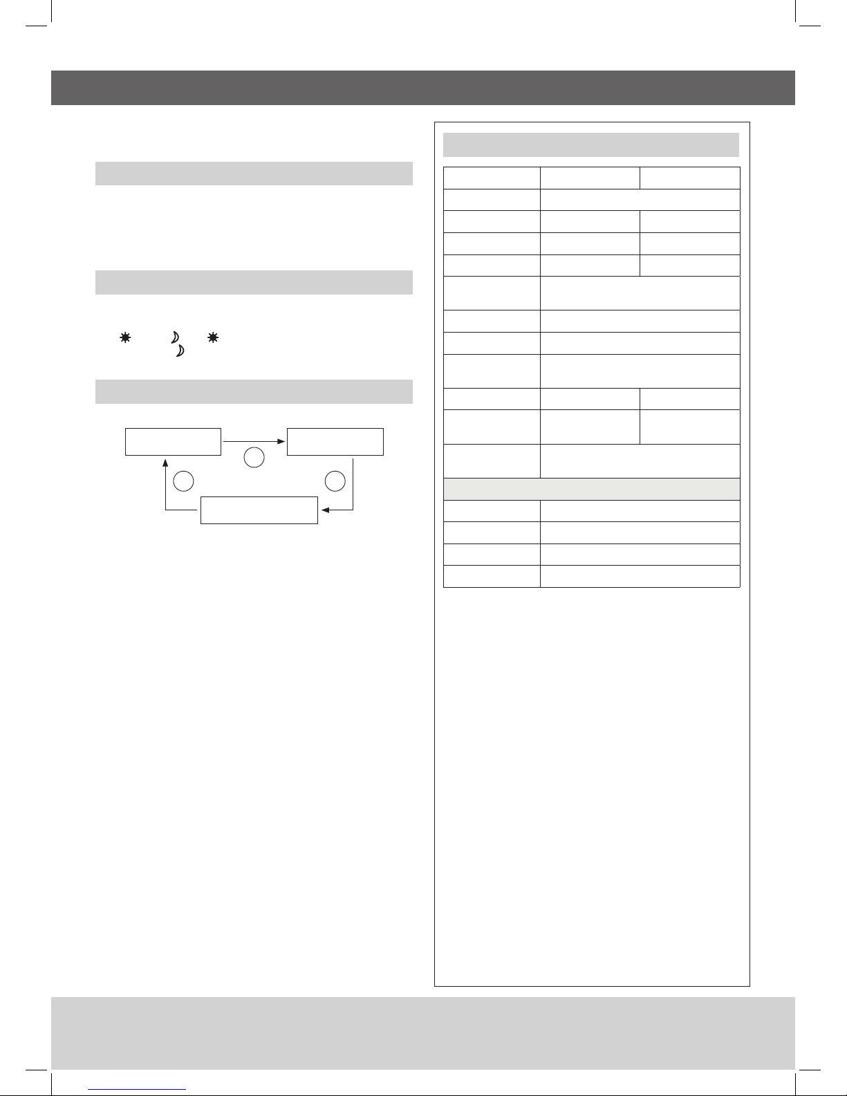
How to change into manual control mode
1. When power is first switched on,the PIR detector enters into the WARM-
UP period for about 1 minute, then automatically changes into AUTO
MODE.
2. During AUTO MODE, by switching the ON/OFF main switch off & on
twice in about 3 seconds, the PIR detector will automatically change into
MANUAL MODE. In MANUAL MODE, the flood light will remain ON for 8
hours. It will not be affected by duration time and Lux control level. After
8 hours, the PIR detector will change back to AUTO MODE.
3. During MANUAL MODE, by switching the ON/OFF main switch off & on
twice in about 3 seconds, the PIR detector will automatically change into
AUTO MODE.
4. During AUTO MODE or MANUAL MODE, by switching off the ON/OFF
main switch over 10 seconds and then on again, the PIR detector will
reset to WARM-UP period.
Cat no. LFS0110WBL LFS0130WBL
Supply voltage
230-240V a.c. 50Hz
Input power
11W 32W
Power ouput
10W 30W
Lumens ouput
730lm 2250lm
Colour
tempertaure
Cool white 4000K nominal
Mounting height
> 2m (recommended)
Protection class
Class 1
Weatherproof
rating
IP44
Size (mm)
115 x 130 x 200 mm 228 x 188 x 270 mm
Weight
(excl packaging)
0.7kg 1.7kg
Power cord
requirement
H05RN-F 3G 1mm
2
PIR sensor
Standby power
< 1.0W
Detection range
12m (max), 180° scan
Time adjustment
10 ±5 sec to 4 ±1 min
Switching function
Auto mode / manual override
POWER ON
1
23
AUTO MODE
MANUAL MODE
Specifications

08/15
LE08110ABA
Disclaimers
1. This product must be installed and used as per these instructions.
2. An IP rating of IP44 is generally considered suitable for external walls with supplementary protection such as overhanging eaves.
3. The IP rating of this product is only valid when installed on a flat and non-porous surface. Additional sealing may be required for irregular surfaces.
4. The fixing screws on this product should be tightened to a maximum torque of 0.8Nm. Over tightening may damage the product.
5. This product contains no serviceable parts and no attempt should be made to repair this product. If the product is faulty it should be discarded.
6. This product is not suitable for installation in hazardous and/or corrosive areas.
7. Electrical installations periodically receive transient over voltages. This product has been designed to minimise the effect of such voltages on connected
equipment. It may not give full protection for extreme over- voltage transients such as those resulting from a close lighting strike.
8. This product utilises intellectual property in the form of registered designs, trademarks, and/or patents. Such intellectual property remains the property of
HPM Legrand in all cases.
9. HPM Legrand reserves the right to modify the specification of this product at any time.
10. This product has been designed to operate in ambient temperatures: -10°C to 40°C.
11. The material in this product may vary in colour from batch to batch. Colour matching from one batch to another cannot be guaranteed.
Warranty
HPM Legrand warrants this product for a period of 3 years from
the date of purchase.
These goods come with guarantees that cannot be excluded
under the Australian and New Zealand Consumer Laws. You
are entitled to a replacement or a refund for a major failure and
for compensation for any other reasonably foreseeable loss
or damage. You are also entitled to have the goods repaired if
the goods fail to be acceptable quality and the failure does not
amount to a major failure.
See the Warranty card enclosed with this product for further
details.
Customer Service
For all Customer Service and Technical Support
please call Monday to Friday during business hours.
HPM Legrand Australia
1300 369 777
www.hpm.com.au
HPM Legrand New Zealand
0800 476 009
www.hpm.co.nz
ABN: 31 000 102 661
 Loading...