

Page 1
Instruction Manual
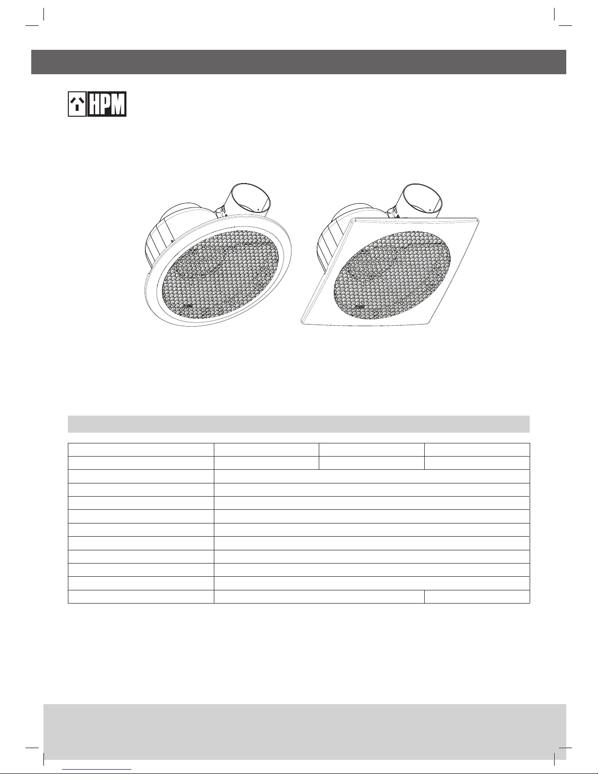
Ceiling Exhaust Fan - Ducted
Cat. No. EFD01RDWE, EFD01RDMS, EFD01SQWE
Specifications
Cat No
EFD01RDWE EFD01RDMS EFD01SQWE
Colour
White Matt Silver White
Supply Voltage
230-240V a.c 50Hz
Power Rating
40W max
Max Airflow Rate (Non-ducted)
330m
3
/hr
Max Airflow Rate (Ducted – Ø150mm x 3m)
250m
3
/hr
Protection Class
Class II
Duct Requirement
Ø150mm
Ceiling Cut-out Size
Ø298mm
Projection into Ceiling
190mm
Protrusion from Ceiling
26mm
Grille Size
Ø372mm 350 x 350 mm
EFD01RDWE/ EFD01RDMS EFD01SQWE
Page 2
Please read carefully
Read through these instructions completely before commencing installation. Retain for future use.
1. This product shall be installed in accordance to AS/NZS 3000 Wiring Rules.
2. Regulations concerning the discharge of air must be fulfilled. Local building codes may require venting to the outside.
3. This product must be installed at least 2.2m above floor level.
4. Do not install within 120cm of a stove or inside a shower recess.
5. Cross Ventilation:
Vent ilati on pro ducts must have an a dequa te so urce of exte rnal air t o ens ure ra ted perf orman ce.
Steam and air will only be exhausted through the fan if there is sufficient flow of air through the room. Ensure adequate inlets exist through windows,
vents or under the door. Airflow path from the inlet to the fan should ideally pass over the source of steam or air to be removed from the room.
Restrictions on replacement air entering the room to be ventilated, or pressure-differentials between the room and outside air will significantly reduce
the exhaust fan’s performance.
6. Compliance with Section 6 Damp Situation of AS/NZS 3000 Wiring Rules:
No part of the unit may be located directly above any part of the bath or shower recess or enclosure.
The unit must be installed within zones 2 and 3 only. For further information, refer to AS/NZS 3000.
7. Unit Orientation:
The unit must be installed to ensure the housing outlet and ducting is oriented in parallel to any roofing structures or supports. Refer to image below
for correct installation orientation. Orientation which forces the unit to be ducted into a 90° bend immediately after the fan outlet will cause a significant
performance reduction.
8. Duct Size and Length:
The unit must be installed with Ø150mm duct using the adaptor supplied to ensure optimum extraction and performance. The maximum recommended
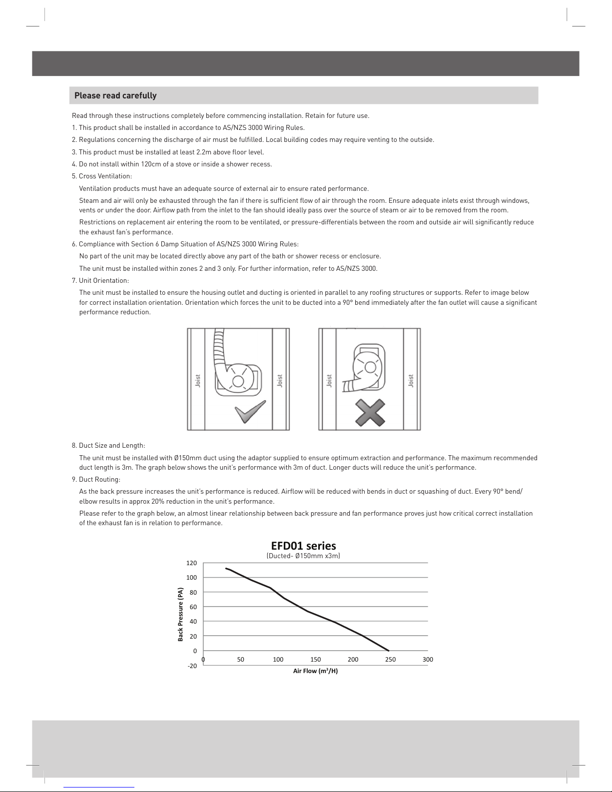
duct length is 3m. The graph below shows the unit’s performance with 3m of duct. Longer ducts will reduce the unit’s performance.
9. Duct Routing:
As the back pressure increases the unit’s performance is reduced. Airflow will be reduced with bends in duct or squashing of duct. Every 90° bend/
elbow results in approx 20% reduction in the unit’s performance.
Please refer to the graph below, an almost linear relationship between back pressure and fan performance proves just how critical correct installation
of the exhaust fan is in relation to performance.
-20
0
20
40
60
80
100
120
0 50 100 150 200 250 300
Back Pressure (PA)
Air Flow (m3/H)
EFD01 series
(Ducted- Ø150mm x3m)
Page 3
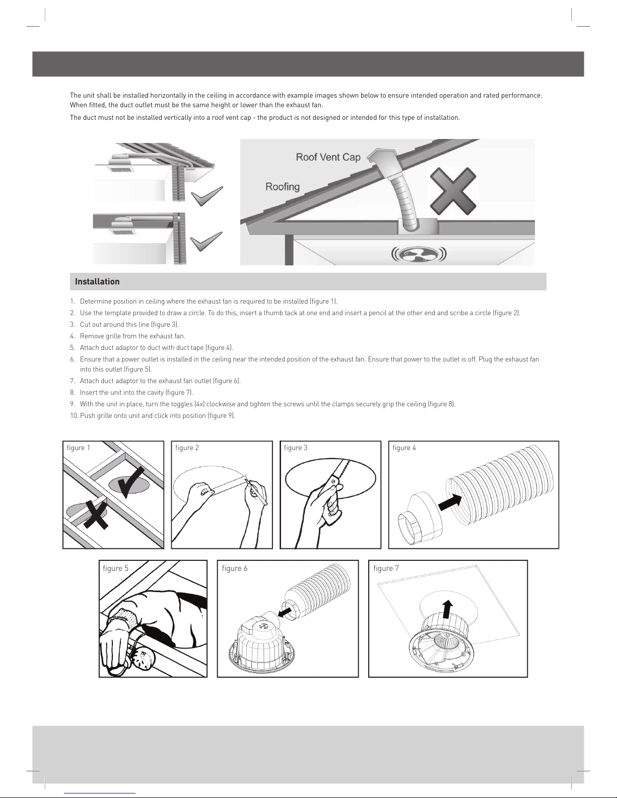
The unit shall be installed horizontally in the ceiling in accordance with example images shown below to ensure intended operation and rated performance.
When fitted, the duct outlet must be the same height or lower than the exhaust fan.
The duct must not be installed vertically into a roof vent cap - the product is not designed or intended for this type of installation.
Installation
1. Determine position in ceiling where the exhaust fan is required to be installed (figure 1).
2. Use the template provided to draw a circle. To do this, insert a thumb tack at one end and insert a pencil at the other end and scribe a circle (figure 2).
3. Cut out around this line (figure 3).
4. Remove grille from the exhaust fan.
5. Attach duct adaptor to duct with duct tape (figure 4).
6. Ensure that a power outlet is installed in the ceiling near the intended position of the exhaust fan. Ensure that power to the outlet is off. Plug the exhaust fan
into this outlet (figure 5).
7. Attach duct adaptor to the exhaust fan outlet (figure 6).
8. Insert the unit into the cavity (figure 7).
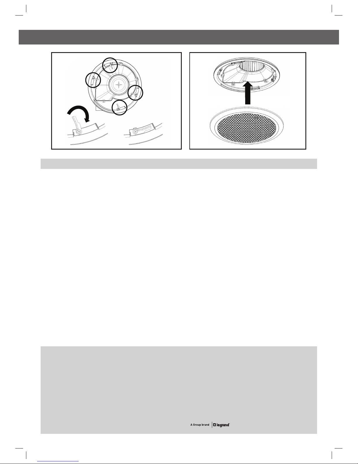
9. With the unit in place, turn the toggles (4x) clockwise and tighten the screws until the clamps securely grip the ceiling (figure 8).
10. Push grille onto unit and click into position (figure 9).
figure 1 figure 2 figure 3 figure 4
Figure
figure 6 figure 7figure 5
Page 4
LE09237AAA 02/2016 HPML0660
Disclaimers
1. This product must be installed and used as per these instructions.
2. This product should only be cleaned with a damp cloth. Cleaning agents and solvents should not be used.
3. This product is not intended for use by persons (including children) with reduced physical, sensory or mental capabilities, or lack of experience and
knowledge, unless they have been given supervision or instruction concerning use of the appliance by a person responsible for their safety. Children should be
supervised to ensure that they do not play with the appliance.
4. This product is intended for household use and similar purposes. It is not suitable for use in and environment heavily laden with dust. Under these conditions
the life of the fan motor can be significantly reduced.
5. This product should not be enclosed in thermal insulation as it may cause the unit to overheat.
6. This product has been designed to operate in ambient temperatures -10°C to 40°C.
7. This product contains no serviceable parts and no attempt should be made to repair it. If the product is faulty it should be discarded.
8. Airflows listed in this product indicate the product performance. Refer to the BCA (Building Code of Australia), or similar, for the appropriate airflow required
for a particular installation.
9. Vent ilati on produ cts m ust h ave a n ade quate sourc e of extern al ai r to ensure c orrect perform ance.
10. Consideration must be taken in the installation of ducts to ensure that condensation that will form in the duct will not run back into the fan housing.
11. Precautions must be taken to avoid the back-flow of gases into the room from the open flue of gas or other fuel-burning appliances.
12. This product has been designed for domestic or similar uses and is not suitable for a commercial installation.
13. This product is not suitable for installation in hazardous and/or corrosive areas.
14. The material in this product may vary in colour from batch to batch. Colour matching from one batch to another cannot be guaranteed.
15. This product utilises intellectual property in the form of registered designs, trademarks, and/or patents. Such intellectual property remains the property of
HPM Legrand in all cases.
16. HPM Legrand reserves the right to modify the specification of this product at any time.
Warranty
HPM Legrand warrants this product for a period of 3 years from
the date of purchase.
These goods come with guarantees that cannot be excluded
under the Australian and New Zealand Consumer Laws. You
are entitled to a replacement or a refund for a major failure and
for compensation for any other reasonably foreseeable loss or
damage. You are also entitled to have the goods repaired if the
goods fail to be acceptable quality and the failure does not amount
to a major failure.
See the Warranty card enclosed with this product for further
details.
Customer Service
For all Customer Service and Technical Support
please call Monday to Friday during business hours.
HPM Legrand Australia
1300 369 777
www.hpm.com.au
HPM Legrand New Zealand
0800 476 009
www.hpm.co.nz
ABN: 31 000 102 661
AFTERBEFORE
figure 8 figure 9
 Loading...