

Page 1
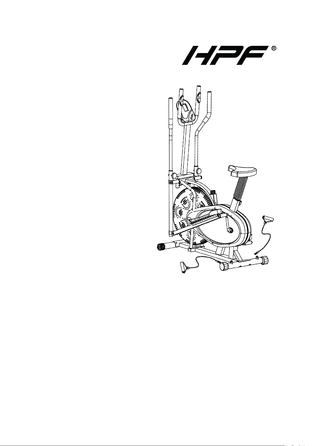
Elliptical Cross-Trainer &
Exercise Bike
User Manual
RETAIN THIS MANUAL FOR FUTURE REFERENCE
PLEASE READ THIS MANUAL CAREFULLY BEFORE USE
Page 2

Elliptical Cross-Trainer & Exercise Bike
Table of Contents
SAFETY REMINDERS ........................................................................................................................................ 1
EXPLODED DIAGRAM ........................................................................................................................................ 2
PARTS LIST ....................................................................................................................................................... 4
ASSEMBLY INSTRUCTIONS .............................................................................................................................. 5
Preparation ................................................................................................................................................... 5
Assembly ...................................................................................................................................................... 5
Reversible Movement .............................................................................................................................. 9
DISPLAY SCREEN ........................................................................................................................................... 10
TROUBLESHOOTING ........................................................................................................................................ 11
Changi ng the Ba tt eries ................................................................................................................................ 11
Computer Not Working Correctly ................................................................................................................. 11
No Resistance ............................................................................................................................................. 11
i
Page 3

Elliptical Cross-Trainer & Exercise Bike
Safety Reminders
Note the following precautions before assembling or operating t he machine:
1. Assemble the machine exactly as what the descriptions indicate in this User Manual.
2. Check all the screws, nuts and other connections before using the mac hine for the first time and ensure that
the cross-trainer is in safe condition.
3. Set-up the machine in a dry, level place and keep it away from moisture and/or water.
4. Place a suitable base (e.g. rubber mat, wooden board etc.) beneath the machine in the area of assembly to
avoid dirt, etc. fr om getting on the floor.
5. Before beginning training, remove all objects within a radius of 2 meter s fr om the machine.
6. Do not use aggressiv e cleaning detergents to clean the machine, only use the supplied tools or suitable t ools
of your own to assemble the machine or repair any parts of m achine. Remove drops of sweat f rom the
machine immediatel y after finishing training.
7. Your health can be affected by incorrect or excessive training. Consult a doctor befor e beginni ng a training
program. The doct or can defi ne the maximum setting ( pulse, watts, duration of training, etc.) to which you
ma y train yoursel f and can get precise information during tr aini ng. This machine is no t s uitable for
therapeutic purpose.
8. Only do training on the machine when it is in correctly working. Use only origi nal spare parts for any
necessary repairs.
9. This machine can accommodate only one person at a time.
10. Wear training clot hes and shoes which are suitable for fitness tr aining with the machine. Your training shoes
should be appropriate for the cross-trainer.
11. If you have a feeling of dizzi ness, sickness or other abnormal sympt oms , please stop training and consult a
doctor.
12. People such as children and handicapped persons should only use the machine i n the presence of another
person who can give aid and advic e.
13. The power of the machine increases with increasing the speed, and vice-versa. The machine is equipped
with an adjustable knob, which can adjust the resistance.
14. The maximum user’s weight is 250 lbs. Persons whose body weight exceeds this lim it should not use this
machine.
1
Page 4
Elliptical Cross-Trainer & Exercise Bike
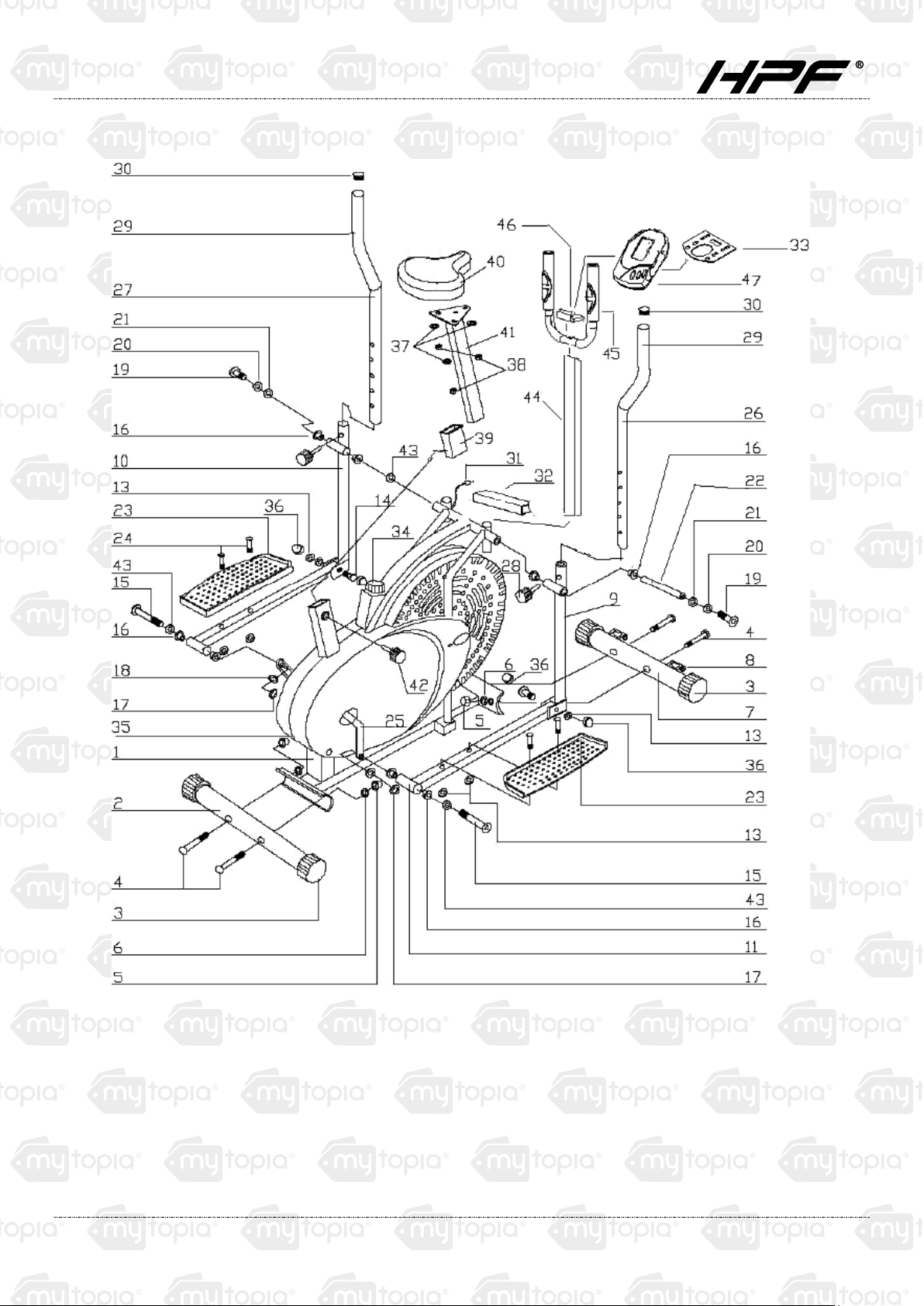
Exploded Diagram
2
Page 5
Elliptical Cross-Trainer & Exercise Bike
3
Page 6

Elliptical Cross-Trainer & Exercise Bike
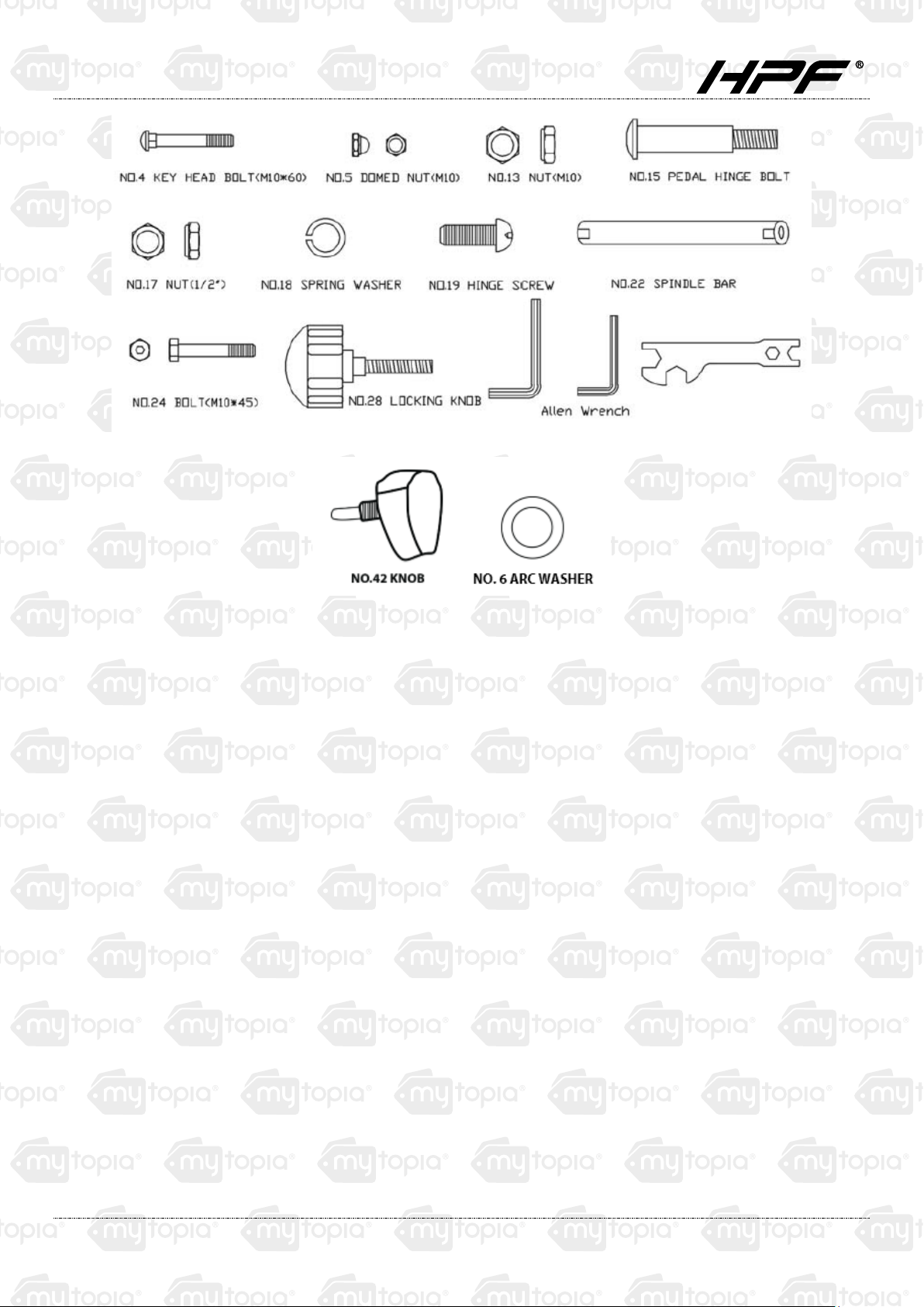
Parts List
NO. NAME QTY. NO. NAME QTY.
1 MAIN FRAME 1 25 CRANK (LEFT&RIGHT) 2
2 REAR STABILIZER 1 26 RIGHT HANDLE B AR 1
3 END CAP 4 27 LEFT HANDLEBAR 1
4 KEY HEAD BOLT (M10*60) 4 28 LOCKING KNOB 4
5 DOMED NUT (M1 0) 4 29 FOAM GRIP 2
6 ARC WASHER 4 30 HANDLE BA R END CA P 2
7 FRONT STABILIZER 1 31 COMPUT ER WIRE 1
8 TRANSPOTTATION WHEEL 2 32 CONNECTING ROD FOR METER 1
9 LOWER HANDLE B AR (RIGHT) 1 33 METER BRACKET 1
10 LOWER HANDLE BAR (LEFT) 1 34 TENSION CONTROL 1
11 RIGHT PEDAL POST 1 35 CHAIN COVER 2
12 LEFT PEDAL POST 1 36 ARC WASHER 4
13 NUT (M10) 4 37 WASHER 3
14 BOLT 2 38 NUT (M8) 3
15 PED AL HINGE BOLT (L & R) 2 39 PLASTIC I NSERT 1
16 STEEL BUSHING 8 40 SADDLE 1
17 NUT (1/2”) (L & R) 2 41 SADDLE POST 1
18 SPRI NG WASHER 2 42 KNOB 1
19 HINGE SC REW 2 43 BUSHING 2
20 SPRI NG WASHER 2 44 METER POST 1
21 D SHAPE WASHER 2 45 HANDLEBAR 1
22 SPINDLE BAR 1 46 CONNECTING PLATE 1
23 PEDAL 2 47 METER 1
24 BOLT (M10*45) 4
4
Page 7

Elliptical Cross-Trainer & Exercise Bike
Assembly Instructions
Preparation
1. Before assembli ng, make sure that you will have s ufficient working space.
2. Use the tools provided for as sembling.
3. Before assembli ng, check whether all needed par ts are available. Refer to the Exploded D iagram
with all s ingle parts (marked with numbers) which this equipment consists of.
Assembly
Attach the Front Stabilizer (No. 7) and the Rear
Stabilizer (No. 2) with four sets of Carr iage Bolts
(N0. 4), Washers ( N o. 6) and Domed N uts (No.
5).
N.B. The Front Stabilizer has the integral
transport wheels.
Figure 1
section
Figure 2
Insert the Spindle Bar (No. 22) through the Right
Lower Handlebar (No. 9) and through the main
frame and then through the arc wa sher (No. 36)
and the Left Handlebar (No. 10).
Put a D-shape Washer and a Spring Washer
(No. 20 & 21) on either side of the Spindle Bar
and tighten both ends us ing the Hinge Screws
(No. 19).
5
Page 8

Elliptical Cross-Trainer & Exercise Bike
•
•
•
BEFORE CONTINUING ASSEMBLY YO U MUST READ THE FOLL OWING
IMPORTANT INFORMATION.
PLEASE NOTE:
ANY DAMAGES TO THE BOLT OR PRODUCT CAUSED BY FAILURE TO FOLLOW THESE STEPS MAY
RENDER THE PRODUCT’S WARRANTY VOID.
IMPORTANT: THE LEFT HAND BOLT AND NUT (BLUE) IS A REVERSE THREAD (ANTI-CLOCKWISE).
The bolt has an L imprinted on the head. Be sure to
use the correct bolt s (m arked L or R) and the correct
nuts (Left-blue/Right-beige) on the appropriate side.
When installing, ensure the wave washer and spring
washer are corr ectly located
Tighten the bolt through the crank arm as pictured.
Ensure the wave washer pushes up hard against the
bolt head once installed.
Tighten the nut on the bolt until the spring was her is
flat against t he crank. As it is a threaded nut, t his will
require extra force.
FAILURE TO FOLLOW THE PROCEDURE EXACTLY
AS DESCRIBED MAY CAUSE DAMAGE TO THE BOLTS/CRANK/NUTS AND COULD VOID YOUR
WARRANTY.
In order to install the hinge bolt properly, keep it
perfectly str aight as the bolt goes t hrough the pedal
tubing and the crankshaft. If the hinge bolt is
connected to the crankshaft at an angle, damage to
both the hinge bolt and t he crankshaft may occ ur.
6
Page 9

Elliptical Cross-Trainer & Exercise Bike
Attach the Pedals (No. 23) to the Pedal Posts
(No. 11 & No. 12), using two M10*45 Bolts (No.
24) and two M10 Nuts (No.13) for each side.
Figure 3
Attach handlebars to the lower handlebar t ubing.
Select a height setting tha t is comfortable for you
and make sure both handlebar s are set at the
same height. Lock eac h handlebar in place with
the locking knobs (No. 28). See Figure 4.
Figure 4
7
Page 10

Elliptical Cross-Trainer & Exercise Bike
•
•
•
•
•
•
•
•
Remove the washer (No. 37) and nut (No.
38) from the saddle (No. 40). Attach the
saddle and saddle post (No. 41) as shown in
Figure 5. Re-insert a nd ti ght en the bolt s.
Put the p lastic insert (No. 39) over the saddle
post then insert t he saddle post into the main
fr ame as shown in Figure 5. Insert and
tighten the knob (No. 42).
Figure 5
Remove the screws and washers from the
back of the meter monitor (No. 47) and put
aside.
Attach the monitor to the handlebar (No. 45)
by inserting onto t he m eter bracket (No. 33)
and feeding the wires through the large
round opening.
Secure the meter monitor w ith the screws
and washers that had previously been
removed, but scr ew into t he upper threads.
Connect the 3 wires on the m eter monitor to
the 3 wires on the handlebar, matching each
with any connection that appropriately fits.
Attach the handlebar to the cross-trainer by
inserting it into the handlebar t ubing holsters
and securing with the locking knobs (No. 28) .
Connect the wire located at the bottom end
Figure 6
of the handlebar with t he wire located at the
front of the main frame.
8
Page 11

Elliptical Cross-Trainer & Exercise Bike
The assembly of your st rider is now complete. P lace plastic caps prov ided on exposed bolt heads if you wish.
For instructions on how to operate the meter refer to the separate instructions manual provided. W hen you try it
for the first time, you should adjust t he tensi on to the correct lev el before you begin a full workout.
For minute-tens ion adjus tment, simply use the Tension Adjustment Knob (pt.34). Turning the adjustment knob
all ows you to change the t ension level and var y the inte nsity of your workout as you exercise.
For greater tension adjustment, you may loosen or tighten the friction belt by re-strapping it. To do so, first turn
the tension adjustment knob to the loosest setting. Then re-strap the belt at the buckle on the top of the fan
wheel just beneath the centre beam.
The more length you allow on the friction belt, the less friction it will cause (less tension). Re-adjust the tension
knob when you are finished.
Reversible Movement
Remember, your strider has a REVERSIBLE movem ent!
Forward pedalling exercises your quadric eps (front thig h muscles), while backward pedalling tar gets your
ham strings (back thigh muscles).
Take advantage of these facts to make your workout less fatiguing and mor e fun.
CAUTION: MAKE SURE YOU THAT HAVE TIGHTENED ALL THE BOLTS AND NUTS WELL BEFORE BEGINNING YOUR
WORKOUT.
NOTE: THE END CAP ON THE FRONT STABILIZER TUBE IS MOVABLE, WHICH WILL BE EASY FOR YOU TO MOVE YOUR
TRAINING BIKE, AND THE END CAP ON THE REAR STABILIZER CAN ADJUST THE PARALLELISM.
9
Page 12

Elliptical Cross-Trainer & Exercise Bike
Display Screen
Button Functions
Mode
Press to select function, and hold on for 4 seconds f or a total reset.
Functions
Scan
Time
Speed
Distance
Calories
NOTE:
1. When you stop exercising, a “STOP” sign will appear on the upper-left corner of the monitor.
2. If there is no signal for a period of 4 minutes, the displa y will shut down automatic ally with all functio n values
stored.
3. Turn on the monitor by pressing the button or by pedalling.
Automatically scans through each function at i ntervals of 6 seconds.
Display s t otal w or k ing time u p to 99:59 minutes.
Display s t he current speed up to 99.9km/h or ml/h. T he v alue will stay on the monitor
continuously.
Display s t otal w or k ing dista nce of up to 99.99km or ml from zero.
Displays calorie consumption during exercise. Maximum value is 9999 calories
(This data is a rough guid e for compar ison of differe nt exercise sessi ons and should not be
used as a basis for medi cal treatment.)
4. If monitor displa y is faulty, please try reinstalling the batteries.
5. Battery spec: 1.5V UM-3 or AA (2pcs).
10
Page 13

Elliptical Cross-Trainer & Exercise Bike
Troubleshooting
Changing the Batteries
1. To change the computer bat teries, please s lide the c om puter from the computer holder, remove the battery
cover on the back of the computer console, and remove the batt eries.
2. Replace with 2 x AA batteries.
3. Finally, put the cov er back on the console, and slide the computer back onto the computer holder.
Computer Not Working Correctly
1. If your computer is not working correct ly, please check whether the c om puter sensor wire is plugg ed into the
computer.
2. If you have checked the above and the computer is still not working, then please make sure that the
batteries are still working and that the y are installed correctly in the computer .
No Resistance
1. If there is no tension resistance, pleas e turn the tension adjustment knob to its lowest le vel, and then go to
the friction belt buckle which is located on top of the fan wheel beneath the centre beam.
2. Loosen the friction belt, pull it through the buckle until you can feel s ome resistance on the belt, and then
lock it back around the buckle.
3. Now mount your Aero Elliptical Strider and turn the pedals.
4. If you find it is now too tight, go back to the friction belt buckle and loosen the belt slightly.
11
Page 14

Some experts believe the incorrect or prolonged use of almost any
product could cause
serious inju
ry or de
a
th. F
or inf
orm
ation th
at
may reduce your risk of serious injury or death consult thepoints
below and additionally, the information available at
www.datastreamserver.com/safety
- Consult all docume ntation, packaging and
product labelling before use. Note that some
products feature online documentation which
should be printed and kept with the p roduct.
- Check product for loose / broken / damaged /
missing parts, wear or leaks (if applicable) before
each use. Never use a product with loose / b roken
/ damaged / missing pa rts, wear or leaks (if
applicable).
- Products must be inspected and serviced (if
applicable) by a qualified specialist every 6
months assuming average residential use by a
person of average weight and strength, ab ove
average technical aptitude, on a property
matching average metropolitan specification.
Intended use outside these guidelines could
indicate the product is not suitable for intended
use or may require more regular inspection or
servicing.
- Ensure all possible users of the p roduct have
completed an industry recognised training course
before being given access to the product.
- The product has been supplied by a general merchandise
retailer that may not be familiar with your specific applic ation or
your description of the applic ation. Be sure to attain third party
approval for your application from a qualified specialist before use
regardless of prior assurances by the retailer or its representatives.
- This product is not intended for use where fail-safe operation is
required. As with any product (take an au tomobile, aircraft,
computer or ball poi nt pen for example) there is always a small
chance of a technical issue that needs to be repaired or may
require replacement of the product or a part. If the possibility of
such failure and the associated time it takes to rectify could in any
situation inconvenience the user, business or employee or could
financially affect the user, business or employee then the product
is not suitable for your requirements. This p roduct is not for use
where incorrect operation or a failure of any kind, including but
not limited to a condition requiring product return, replacement,
service by a technician or replacement of parts could cause a
financial loss, loss of employee time or an in c
onvenience
requiring compensation.
- If this item has been purchased in error considering the points
above simply contact the retailer directly for details of their
returns policies if required.
 Loading...