

Page 1

HPE PSR150-A & PSR150-D Series
Power Supplies User Guide
Part number: 5998-1613u
Document version: 6PW106-20160930
5998-1613u
Page 2

© Copyright 2015, 2016 Hewlett Packard Enterprise Development
LP
The information contained herein is subject to change without notice.
The only warranties for Hewlett Packard Enterprise products and
services are set forth in the express warranty statements
accompanying such products and services. Nothing herein should be
construed as constituting an additional warranty. Hewlett Packard
Enterprise shall not be liable for technical or editorial errors or
omissions contained herein.
Confidential computer software. Valid license from Hewlett Packard
Enterprise required for possession, use, or copying. Consistent with
FAR 12.211 and 12.212, Commercial Computer Software, Computer
Software Documentation, and Technical Data for Commercial Items
are licensed to the U.S. Government under vendor’s standard
commercial license.
Links to third-party websites take you outside the Hewlett Packard
Enterprise website. Hewlett Packard Enterprise has no control over
and is not responsible for information outside the Hewlett Packard
Enterprise website.
Acknowledgments
Intel®, Itanium®, Pentium®, Intel Inside®, and the Intel Inside logo
are trademarks of Intel Corporation in the United States and other
countries.
Microsoft® and Windows® are trademarks of the Microsoft group of
companies.
Adobe® and Acrobat® are trademarks of Adobe Systems
Incorporated.
Java and Oracle are registered trademarks of Oracle and/or its
affiliates.
UNIX® is a registered trademark of The Open Group.
Page 3

Contents
Introduction to the power supply ························ 1
Specifications ············································································· 3
Panel ·························································································· 4
Installing and removing the power supply ·········· 8
Precautions ················································································· 8
Tools ··························································································· 9
Installing and removing the power supply ·································· 9
Installing the power supply ···················································· 9
Removing the power supply ················································ 11
Connecting the power cord ······················································· 11
Connecting an AC power cord ············································ 12
Connecting the DC power cord ··········································· 12
Document conventions and icons ···················· 14
Conventions ·············································································· 14
Network topology icons ···························································· 16
Support and other resources ···························· 18
Accessing Hewlett Packard Enterprise Support ······················· 18
Accessing updates ··································································· 18
Websites ·············································································· 19
Customer self repair ···························································· 20
Remote support ··································································· 21
Documentation feedback ····················································· 21
i
Page 4

Introduction to the power supply
The PSR150-A (JD362A) and PSR150-A1 (JD362B) are AC-input
and DC-output power supplies; the PSR150-D (JD366A) and
PSR150-D1 (JD366B) are DC-input and DC-output power supplies.
These power supplies can convert the input voltage to 12 V that is
required by the powered device, and their maximum output power is
150 W.
Table 1 Supported features
Feature Description
Protection
Redundancy
Hot swapping
Auto-recovery support of the power supplies in protection state is
shown in Table 2.
Output over-voltage protection, output
short-circuit protection, output current-limiting
protection, and overheat protection.
Supports parallel connection of two power
supplies, thus implementing 1+1 redundant
current sharing.
When the device operates properly, you can
power off a power supply of the 1+1 redundant
power supply system and remove it from the
device.
1
Page 5

Table 2 Protection functions
Protection
function
Over-voltage
protection
Short-circuit
protection
Current-limiting
protection
Overheat
protection
Status
No power is supplied
because the power
supply is deadly
locked.
No power is supplied
because the power
supply is deadly
locked.
No power is supplied
because the power
supply is deadly
locked.
No power is supplied.
Auto-recovery
support
Not supported
Not supported
Not supported
Restoring power
supply after the
temperature
decreases
2
Page 6

NOTE:
When a power supply is deadly locked, it does not support the
auto-recovery function. Follow these procedures to restore the
device:
• Disconnect the power cord from the power source.
• Unplug the power cord from the power supply and then
insert it again.
• Connect the power cord to the power source and restart the
device.
In case of overheat protection, take measures to decrease the
temperature of the device. The power supply recovers after the
temperature falls.
Specifications
Table 3 Specifications
Item Specifications
PSR150-A/PSR150-A1(JD362A/JD362B):
Rated voltage
range
Max voltage range
Output voltage 12 V
Max output current 12.5 A
Max output power 150 W
100 VAC to 240 VAC @ 50 Hz or 60 Hz
PSR150-D/PSR150-D1(JD366A/JD366B):
–48 VDC to –60 VDC
PSR150-A/PSR150-A1(JD362A/JD362B):
90 VAC to 264 VAC @ 47 Hz to 63 Hz
PSR150-D/PSR150-D1(JD366A/JD366B):
–36 VDC to –72 VDC
3
Page 7
Item Specifications
Dimensions (H × W
× D)
Operating
temperature
Storage
temperature
41.1 × 101.6 × 177 mm (1.62 × 4.00 × 6.97
in)
–5°C to +55°C (25°F to 131°F)
–40°C to +70°C (–40°F to +158°F)
Panel
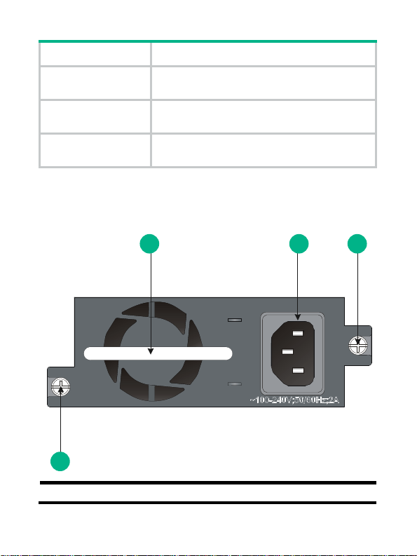
Figure 1 Panel of the PSR150-A(JD362A)
1 2 3
3
(1) Power supply handle (2) AC receptacle
4
Page 8

(1) Power supply handle (2) AC receptacle
(3) Captive screws
Figure 2 Panel of the PSR150-A1(JD362B)
1 2 3
3
(1) Power supply handle (2) AC receptacle
(3) Captive screws
5
Page 9

Figure 3 Panel of the PSR150-D(JD366A)
1 2
2 3 4 3
(1) Power supply handle (2) Captive screws
(3) Screw holes of the plug (4) DC power receptacle
6
Page 10

Figure 4 Panel of the PSR150-D1(JD366B)
1 2
2 3 4 3
(1) Power supply handle (2) Captive screw
(3) Screw holes of the plug (4) DC power receptacle
7
Page 11

Installing and removing the power supply
This chapter describes how to install and remove the power supply
and the power cord. To prevent damage to the device and personal
injury, follow the installation and removal procedures illustrated
in Figure 5 and Figure 6, respectivel
Figure 5 Installation procedure
Figure 6 Removal procedure
Precautions
When installing and removing a power supply, follow these
guidelines:
• Wear an ESD-preventive wrist strap and make sure the wrist
strap makes good skin contact.
• Make sure the operating voltage provided by the power source
is consistent with that marked on the power supply, and the
output voltage of the power supply is consistent with the
powered device, preventing damage to the power supply and
powered device.
y.
8
Page 12

• Do not touch any naked wire or terminal. Doing so may result in
a personal injury.
• Never place the power supply in wet locations and prevent fluid
from leaking into the power supply.
• Do not often open the shell of the power supply to prevent
damage to the power supply. If a failure occurs on the internal
wires or units, contact the technical stuff to troubleshoot the
problem.
Tools
Prepare the following tools for installation and removal:
• Flat-blade screwdriver
• Phillips screwdriver
• ESD-preventive wrist strap
Installing and removing the power supply
CAUTION:
Before installation and removal, make sure no power cord is
connected to the power supply.
The installation/removal procedures of the PSR150-A, PSR150-A1,
PSR150-D, and PSR150-D1(JD362A, JD362B, JD366A, or JD366B)
are similar. This document takes the PSR150-A(JD362A) as an
example to describe the installation and removal of the power supply.
Installing the power supply
1. Wear an ESD-preventive wrist strap, and make sure the wrist
strap makes good skin contact and is well grounded.
2. Unpack the power supply and verify that the input mode of the
power supply is as required.
9
Page 13

3. Face the slot where the power supply is to be installed.
4. Insert the power supply with the upside up (if you insert it with
the upside down, the insertion is not smooth because of the
specific structure design of the power supply and slot). Grasping
the handle of the power supply with one hand and supporting
the power supply bottom with the other, slide the supply slowly
along the guide rails into the slot (see callout 1 in Figure 7).
5. Fasten the captive screws on the power supply with a Phillips
screwdriver until the power supply seats into the chassis (see
callout 2 in Figure 7).
Figure 7 Installing a power supply
10
Page 14

NOTE:
• If the slot has a filler module, remove it before inserting the
power supply.
• To prevent damage to the power supply or the connector on
the backplane of the powered device, insert the power
supply gently. If you encounter a hard resistance while
inserting the power supply, pull out the power supply and
then insert it again.
• If the captive screw cannot be tightly fastened, examine the
installation of the power supply.
Removing the power supply
1. Wear an ESD-preventive wrist strap, and make sure the wrist
strap makes good skin contact and is well grounded.
2. Disconnect the power cord from the power supply and the
external power supply.
3. Face the power supply to be removed from the powered device.
4. Loosen the captive screws on the power supply with a Phillips
screwdriver until the captive screws are disengaged from the
powered device.
5. Grasping the handle of the power supply with one hand, pull it
part way out. Then supporting the power supply bottom with the
other hand, pull the power supply slowly along the guide rails
out of the slot.
Put the power supply into an antistatic bag after removal.
Connecting the power cord
After you insert the power supply into the device, you can connect the
power cord. For an AC-powered device, use an AC power cord to
connect the power source; for a DC-powered device, use a DC
power cord to connect the power source.
11
Page 15

Connecting an AC power cord
1. Connect one end of the AC power cord shipped with the device
to the AC receptacle on the power supply (see Figure 8).
2. Connect the oth
er end of the AC power cord to the power
source.
Figure 8 Connecting an AC power cord
Connecting the DC power cord
CAUTION:
The power cord color code scheme in Figure 9 is
only. The cable delivered for your country or region might use a
different color scheme. When you connect a power cord, always
identify the polarity symbol on its wires.
To connect the DC power cord:
1. Insert the DC connector into the DC power receptacle. See
callout 1 inFigure 9.
for illustration
12
Page 16

The connector of the DC power cord and the DC power
receptacle are foolproof. Make sure the connector is correctly
oriented.
2. Use a flat-blade screwdriver to fasten the two screws on the DC
plug to secure the plug to the DC receptacle (see callout 2
inFigure 9).
3. Connect the other ends of the wires to the DC power source
wiring terminals, with the negative wire (– or L–) to the negative
terminal (–) and the positive wire (+ or M/N) to the positive
terminal (+).
Figure 9 Connecting the DC power cord
2
2
1
13
Page 17

Document conventions and icons
Conventions
This section describes the conventions used in the documentation.
Port numbering in examples
The port numbers in this document are for illustration only and might
be unavailable on your device.
Command conventions
Convention Description
Boldface
Italic
[ ]
{ x | y | ... }
[ x | y | ... ]
{ x | y | ... } *
Bold text represents commands and keywords
that you enter literally as shown.
text represents arguments that you
Italic
replace with actual values.
Square brackets enclose syntax choices
(keywords or arguments) that are optional.
Braces enclose a set of required syntax
choices separated by vertical bars, from which
you select one.
Square brackets enclose a set of optional
syntax choices separated by vertical bars, from
which you select one or none.
Asterisk marked braces enclose a set of
required syntax choices separated by vertical
bars, from which you select at least one.
14
Page 18

Convention Description
Asterisk marked square brackets enclose
optional syntax choices separated by vertical
[ x | y | ... ] *
bars, from which you select one choice,
multiple choices, or none.
The argument or keyword and argument
&<1-n>
combination before the ampersand (&) sign
can be entered 1 to n times.
#
A line that starts with a pound (#) sign is
comments.
GUI conventions
Convention Description
Window names, button names, field names,
Boldface
and menu items are in Boldface. For example,
the New User window appears; click OK.
>
Multi-level menus are separated by angle
brackets. For example, File > Create > Folder.
Symbols
Convention Description
An alert that calls attention to important
WARNING!
CAUTION:
information that if not understood or
followed can result in personal injury.
An alert that calls attention to important
information that if not understood or
followed can result in data loss, data
corruption, or damage to hardware or
software.
15
Page 19

Convention Description
IMPORTANT:
NOTE:
An alert that calls attention to essential
information.
An alert that contains additional or
supplementary information.
TIP:
An alert that provides helpful information.
Network topology icons
Convention Description
Represents a generic network device, such as
a router, switch, or firewall.
Represents a routing-capable device, such as
a router or Layer 3 switch.
Represents a generic switch, such as a Layer 2
or Layer 3 switch, or a router that supports
Layer 2 forwarding and other Layer 2 features.
Represents an access controller, a unified
wired-WLAN module, or the access controller
engine on a unified wired-WLAN switch.
Represents an access point.
T
T
Represents a wireless terminator unit.
16
Page 20

Convention Description
T
T
Represents a wireless terminator.
Represents a mesh access point.
Represents omnidirectional signals.
Represents directional signals.
Represents a security product, such as a
firewall, UTM, multiservice security gateway, or
load balancing device.
Represents a security card, such as a firewall,
load balancing, NetStream, SSL VPN, IPS, or
ACG card.
17
Page 21

Support and other resources
Accessing Hewlett Packard Enterprise Support
• For live assistance, go to the Contact Hewlett Packard
Enterprise Worldwide website:
www.hpe.com/assistance
o access documentation and support services, go to the
• T
Hewlett Packard Enterprise Support Center website:
www.hpe.com/support/hpesc
Information to col
• Technical support registration number (if applicable)
• Product name, model or version, and serial number
• Operating system name and version
• Firmware version
• Error messages
• Product-specific reports and logs
• Add-on products or components
• Third-party products or components
Accessing updates
• Some software products provide a mechanism for accessing
software updates through the product interface. Review your
product documentation to identify the recommended software
update method.
• To download product updates, go to either of the following:
lect
18
 Loading...