

HPE X130 10G SFP+ LC SR, X130 10G SFP+ LC ER, X130 10G SFP+ LC LH, X130 10G SFP+ LC LR, X240 10G SFP+ SFP+ 3m User Manual
...Page 1

HPE Comware-Based Devices Transceiver
Modules
User Guide (10G)
Part number: 5200-2358c
Document version: 6W103-20190408
Page 2

© Copyright 2017, 2019 Hewlett Packard Enterprise Development LP
The information contained herein is subject to change without notice. The only warranties for Hewlett Packard
Enterprise products and services are set forth in the express warranty statements acco mpanying such
products and services. Nothing herein should be construe d as constituting an additional warranty. Hewlett
Packard Enterprise shall not be liable for technical or editorial errors or omissions co ntained herein.
Confidential computer software. V alid license from Hewlett Packard Enterprise required for possession, use, or
copying. Consistent with FAR 12.211 and 12.212, Commercial Computer Software, Computer Software
Documentation, and T e chnical Data for Commercial Items are licensed to the U.S. Government under vendor’s
standard commercial license.
Links to third-party websites take you outside the Hewlett Packard Enterprise website. Hewlett Packard
Enterprise has no control over and is not responsible for information outside the Hewlett Packard Enterprise
website.
Acknowledgments
Intel®, Itanium®, Pentium®, Intel Inside®, and the Intel Inside logo are trademarks of Intel Corporation in the
United States and other countries.
Microsoft® and Windows® are either registered trademarks or trademarks of Microsoft Corporation in the
United States and/or other countries.
Adobe® and Acrobat® are trademarks of Adobe Systems In corporated.
Java and Oracle are registered trademarks of Oracle and/or its affiliates.
UNIX® is a registered trademark of The Open Group.
Page 3

Contents
Overview ························································································1
List of 10-Gigabit transceiver modules and network cables ·································································· 1
About optical transceiver modules ··································································································· 1
Data rate ····························································································································· 1
Transmission distance ············································································································ 1
Central wavelength ················································································································ 2
Fiber ··································································································································· 2
LC connector ························································································································ 3
Optical parameters ················································································································ 4
SFP+ transceiver modules ·································································5
SFP+ optical transceiver modules ··································································································· 5
Models and specifications ······································································································· 5
SFP+ copper cables ····················································································································· 7
Models and specifications ······································································································· 7
SFP+ active optical cables ············································································································· 7
Models and specifications ······································································································· 8
XFP transceiver modules ···································································9
Models and specifications ·············································································································· 9
CX4 copper cables ········································································· 12
Models and specifications ············································································································ 12
10-Gigabit Ethernet transceiver modules compatibility matrix ··················· 13
10-Gigabit Ethernet transceiver modules ························································································ 13
Switching minimum software release requirements ··········································································· 14
HPE FlexFabric 12900 switch series minimum software version requirements ································ 14
HPE FlexFabric 12900E switch series minimum software version requirements ······························ 18
HPE FlexFabric 11900 switch series minimum software version requirements ································ 20
HPE FlexFabric 10500 switch series minimum software version requirements ································ 21
HPE FlexFabric 7900 switch series minimum software version requirements ·································· 30
HPE FlexFabric 7500 switch series minimum software version requirements ·································· 31
HPE 6127XLG Blade switch series minimum software version requirements ·································· 37
HPE 6125XLG Blade switch series minimum software version requirements ·································· 38
HPE FlexFabric 5980 switch series minimum software version requirements ·································· 39
HPE FlexFabric 5950 switch series minimum software version requirements ·································· 39
HPE FlexFabric 5945 switch series minimum software version requirements ·································· 41
HPE FlexFabric 5940 switch series minimum software version requirements ·································· 42
HPE FlexFabric 5930 switch series minimum software version requirements ·································· 43
HPE FlexFabric 5920 switch series minimum software version requirements ·································· 45
HPE FlexFabric 5900 switch series minimum software version requirements ·································· 45
HPE FlexFabric 5830 switch series minimum software version requirements ·································· 48
HPE FlexFabric 5710 Switch series minimum software version requirements ································· 49
HPE FlexFabric 5700 switch series minimum software version requirements ·································· 50
Document conventions and icons ······················································ 54
Conventions ······························································································································ 54
Network topology icons ··············································································································· 55
Support and other resources····························································· 56
Accessing Hewlett Packard Enterprise Support················································································ 56
Accessing updates ····················································································································· 56
Websites ··························································································································· 57
Customer self repair ············································································································ 57
Remote support ·················································································································· 57
Documentation feedback ······································································································ 58
i
Page 4

Index ··························································································· 59
ii
Page 5

Overview
Transceiver module type
Connector type
CX4 copper cables
NOTE:
•
transceiver modules and cables, contact HPE technical support or
•
modules compatibility matrix".
This document describes 10-Gigabit transceiver modules and cables available for HPE Comwarebased devices.
List of 10-Gigabit transceiver modules and network cables
SFP+ transceiver modules
SFP+ optical transceiver module LC
SFP+ copper cable (for interconnecting devices)
SFP+ active optical cable
XFP transceiver modules
10-Gigabit small form-factor pluggable (XFP) module (transceiver)
10-Gigabit CX4 copper cable (for interconnecting devices) N/A
HPE 10-Gigabit transceiver modules and cables are subject to change over time. For the most
recent list of HPE 10-Gigabit
marketing staff.
The available transceiver modules and cables vary by HPE devices. For the transceiver
modules and cables available for a device, see the installation guide for the device. For the 10Gigabit transceiver modules and cables for a switch, see "
10-Gigabit Ethernet transceiver
About optical transceiver modules
Optical transceiver modules (also called fiber transceiver modules) transmit signals over optical
fibers and are suitable for long distance transmission.
N/A
LC
The following information explains the major specifications of a fiber transceiver module.
Data rate
Data rate is the number of bits transmitted per second. Data rate is typically measured in Gigabits
per second (Gbps).
Transmission distance
The transmission distance of optical transceiver modules is divided into short and long-range types.
Typically, a distance of 2 km (1.24 miles) or below is short-range type and a distance of 10 km (6.21
miles) is long-range type.
1
Page 6

Transmission distances supported by optical transceiver modules are mainly limited by signal
•
•
•
•
•
Fiber grade
Fiber diameter (μm)
Modal bandwidth at 850 nm (MHz*km)
Interface type
Central wavelength (nm)
Fiber grade
Transmission distance
attenuation and dispersion suffered during the transmission of fiber signals over fibers.
Signal attenuation occurs because of absorption, dispersion, and leakage over the media as
light travels through optical fibers. This attenuation increases in direct ratio to transmission
distance.
Dispersion occurs because a fiber transmits light with different wavelengths at different
speeds. Light with different wavelengths reaches the receiving end at different time. This
results in spread and blurred pulses.
Central wavelength
Central wavelength represents the wave band used for optical signal transmission. The following
central wavelengths (wave bands) are available for common optical transceiver modules: 850 nm,
1310 nm, and 1550 nm.
The 850 nm wave band is used for short-reach transmission.
The 1310 nm and 1550 nm wave bands are used for middle-reach and long-haul
transmissions.
Fiber
Fiber types
Fibers are classified into multimode fibers and single-mode fibers.
Multimode fibers
Multimode fibers (MMFs) have thicker fiber cores than single-mode fibers and can transport
light in multiple modes. However, the intermodal dispersion is greater and worsens as the
transmission distance increases.
Multimode fibers can be classified into multiple grades according to their diameters and modal
bandwidth, as shown in Table 1. The modal bandwidth is a comprehensive index that reflects
the optical characteristics of a multimode fiber. The modal bandwidth of a multimode fiber is
equal to the modulation frequency of the maximum modulation frequency pulse that can pass
a fiber × the fiber length.
International Telecommunication Union (ITU) defines multimode fiber types in its G series
standards. The most commonly used multimode fiber is defined in the ITU G.651 standard.
The G.651-compliant fiber transmits light in the wavelength range of 800 nm to 900 nm or
1200 nm to 1350 nm.
Table 1 Multimode fiber grades
OM1 62.5/125 200
OM2 50/125 500
OM3 50/125 2000
OM4 50/125 4700
Other factors that determine the transmission distance of multimode fibers include interface
type, central wavelength, and fiber grade, as shown in Table 2.
Table 2 Multimode fiber specifications
1000BASE-SX 850 OM1 < 275 m (902.23 ft)
2
Page 7
Interface type
Central wavelength (nm)
Fiber grade
Transmission distance
OM2 < 550 m (1804.46 ft)
•
Single-mode fiber type
Wavelength (nm)
Features
Applications
•
•
•
CAUTION:
Cover the connector with a dust cap when it is not connected to optical fibers.
OM1 < 33 m (108.27 ft)
10GBASE-SR 850
10GBASE-LRM 1310
Single-mode fibers
OM2 < 82 m (269.03 ft)
OM3 < 300 m (984.25 ft)
OM4 < 450m (1476.38 ft)
OM1 < 220 m (721.78 ft)
OM2 < 220 m (721.78 ft)
OM3 < 220 m (721.78 ft)
OM4 < 220 m (721.78 ft)
Single-mode fibers (SMFs) have a small core size (typically 9 μm or 10 μm) and can transmit
light in only one mode. Single-mode fibers suffer little intermodal dispersion and are suitable
for long-haul communication. Single-mode fibers transmit light at the central wavelength of
1310 nm or 1550 nm.
Telecommunication Industries Alliance (TIA)/Electronic Industries Alliance (EIA) defines that
single-mode fibers use yellow outer jackets with an "SM" mark.
ITU defines single-mode fiber types in its G series standards. The most commonly used
single-mode fibers are defined in ITU G.652 and G.655 standards. Table 3 describes features
of the G.652 and G.655-compliant fibers.
Table 3 Features of G.652 and G.655-compliant fibers
G.652-compliant fiber
(standard single-mode
fiber)
G.655-compliant fiber
(non-zero dispersion
shifted fiber)
Fiber diameter
Fiber diameter is expressed as core diameter/cladding diameter, in μm. For example, 9/125 μm
represents a fiber core diameter of 9 μm and a fiber cladding diameter of 125 μm.
As a best practice, use the following fiber diameters for the HPE Comware-based devices:
G.652 standard single-mode fiber—9/125 μm.
G.655 single-mode fiber—9/125 μm.
G.651 standard multimode fiber—50/125 μm or 62.5/125 μm.
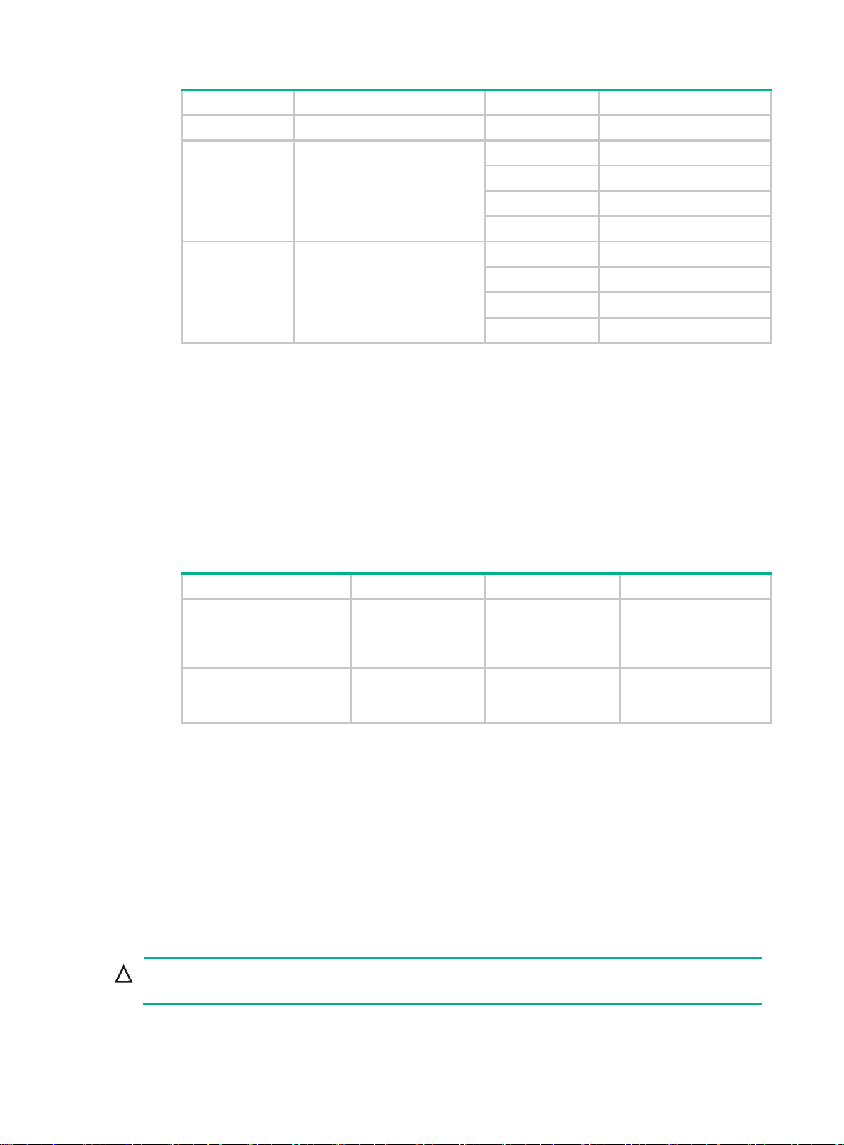
LC connector
• 1260 to 1360
• 1530 to 1565
1530 to 1565
Zero dispersion at
1310 nm.
Near-zero dispersion
around 1550 nm.
Connecting transceiver
modules with a central
wavelength of 1310 nm
or 1550 nm.
1550-nm wavelengthdivision multiplexing
(WDM) transmissions.
3
Page 8
Connectors connect transceiver modules to the transmission media.
•
•
Figure 1 LC connector
Optical parameters
The following are the major optical parameters:
Transmit power—Transmit power is the power at which the transmitter of an optical
transceiver module transmits optical signals, in dBm.
Receive power—Receive power is the power at which the receiver of a optical transceiver
module receives optical signals, in dBm.
The transceiver module specifications in this guide provide the average transmit and receive power
ranges.
4
Page 9
SFP+ transceiver modules
(nm)
(µm)
(MHz*km)
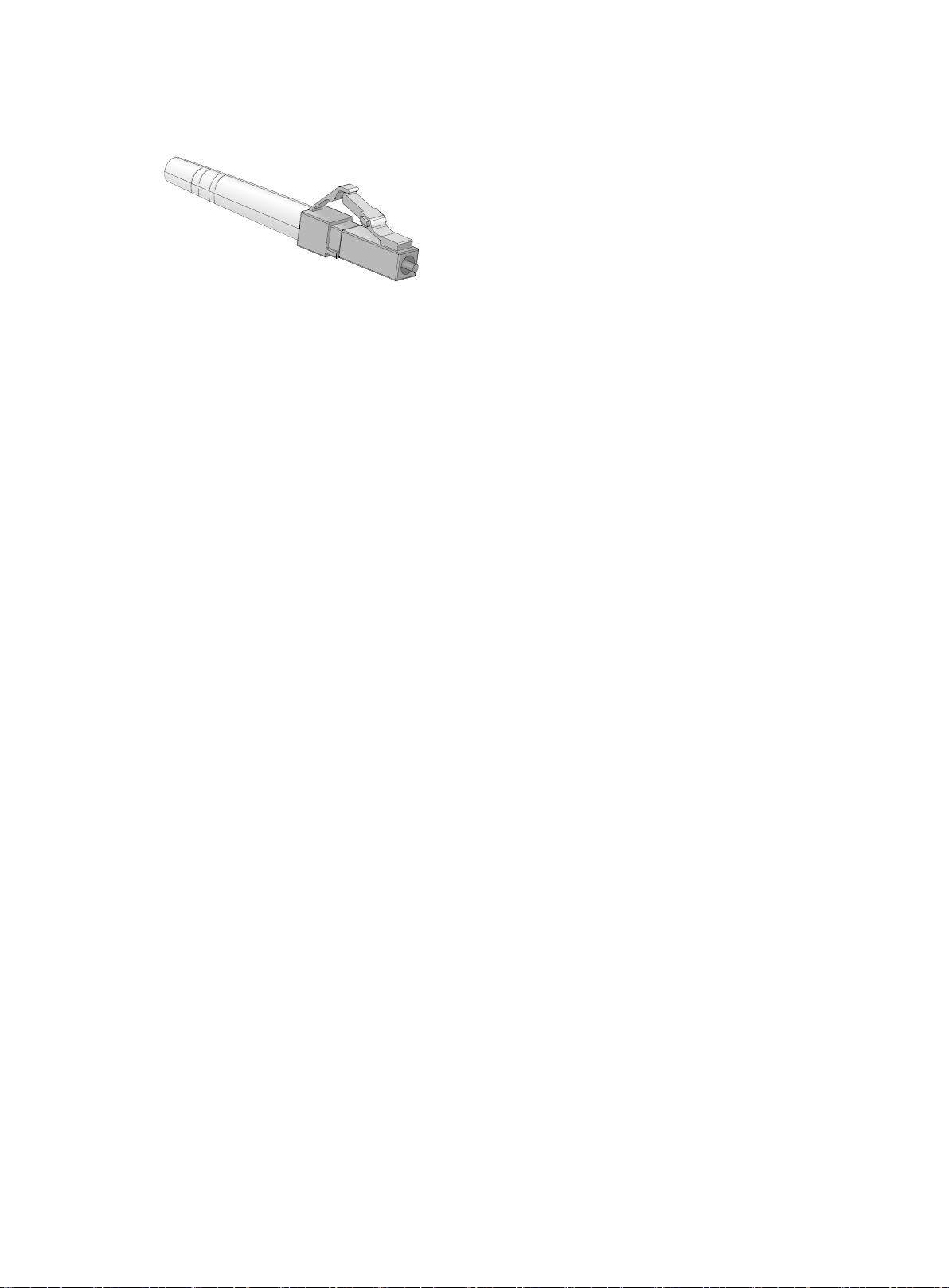
SFP+ optical transceiver modules
Figure 2 SFP+ optical transceiver module
Models and specifications
SFP+ optical transceiver modules provide a transmission rate of 10.31 Gbps and use LC connectors.
Table 4 Specifications for SFP+ optical transceiver modules (1)
Product
code
JD092B
JQ431A
JD093B
HPE
description
HPE X130 10G
SFP+ LC SR
Transceiver
HPE X130 10G
SFP+ LC SR
Data Center
Advanced
Transceiver
HPE X130 10G
SFP+ LC LRM
Transceiver
Central
wavelength
850 MMF
850 MMF
1310 MMF
Fiber
mode
Fiber
diameter
50/125
62.5/125
50/125
62.5/125
50/125
62.5/125
Modal
bandwidth
2000 300 m (984.25 ft)
500 82 m (269.03 ft)
400 66 m (216.54 ft)
200 33 m (108.27 ft)
160 26 m (85.30 ft)
2000 300 m (984.25 ft)
500 82 m (269.03 ft)
400 66 m (216.54 ft)
200 33 m (108.27 ft)
160 26 m (85.30 ft)
1500 220 m (721.78 ft)
500 220 m (721.78 ft)
400 100 m (328.08 ft)
200 220 m (721.78 ft)
160 220 m (721.78 ft)
Transmission
distance
JD094B
HPE X130 10G
SFP+ LC LR
Transceiver
1310 SMF 9/125 N/A 10 km (6.21 miles)
5
Page 10

Product
(nm)
(µm)
(MHz*km)
Optical parameters (dBm)
Transmit power
Receive power
NOTE:
•
•
SFP+ transceiver modules. Cold boot time within 90 seconds is acceptable for the module.
code
JQ432A
JG234A
JG915A
JL250A
HPE
description
HPE X130 10G
SFP+ LC LR
Data Center
Advanced
Transceiver
HPE X130 10G
SFP+ LC ER
40km
Transceiver
HPE X130 10G
SFP+ LC LH
80km
Transceiver
HPE X130 10G
SFP+ LC LH80
tunable
Transceiver
Central
wavelength
1310 SMF 9/125 N/A 10 km (6.21 miles)
1550 SMF 9/125 N/A
1550 SMF 9/125 N/A
1547.75 SMF 9/125 N/A
Fiber
mode
Fiber
diameter
Table 5 Specifications for SFP+ optical transceiver modules (2)
Modal
bandwidth
Transmission
distance
40 km (24.86
miles)
80 km (49.71
miles)
80 km (49.71
miles)
Product
code
JD092B
JQ431A
JD093B
JD094B
JQ432A
JG234A
JG915A
JL250A
HPE description
HPE X130 10G SFP+ LC SR
Transceiver
HPE X130 10G SFP+ LC SR Data
Center Advanced Transceiver
HPE X130 10G SFP+ LC LRM
Transceiver
HPE X130 10G SFP+ LC LR
Transceiver
HPE X130 10G SFP+ LC LR Data
Center Advanced Transceiver
HPE X130 10G SFP+ LC ER 40km
Transceiver
HPE X130 10G SFP+ LC LH 80km
Transceiver
HPE X130 10G SFP+ LC LH80 tunable
Transceiver
–7.3 to –1 –9.9 to +0.5
–7.3 to –1 –9.9 to +0.5
–6.5 to +0.5 –6.5 to +1.5
–8.2 to +0.5 –14.4 to +0.5
–8.2 to +0.5 –14.4 to +0.5
–4.7 to +4 –15.8 to –1
0 to +4 –24 to –7
–1 to +3 –24 to –7
A mode conditioning patch cord is required when you use OM1 or OM2 fiber types on an HPE
X130 10G SFP+ LC LRM Transceiver (JD093B). Never use mode conditioning patch cords for
OM3 fiber types. For more information about mode conditioning patch cords, see related parts
in the IEEE 802.3 standard.
An HPE X130 10G SFP+ LC LH80 tunable Transceiver (JL250A) supports tunable
wavelengths. Therefore, cold boot for the module takes longer than cold boot for common
6
Page 11
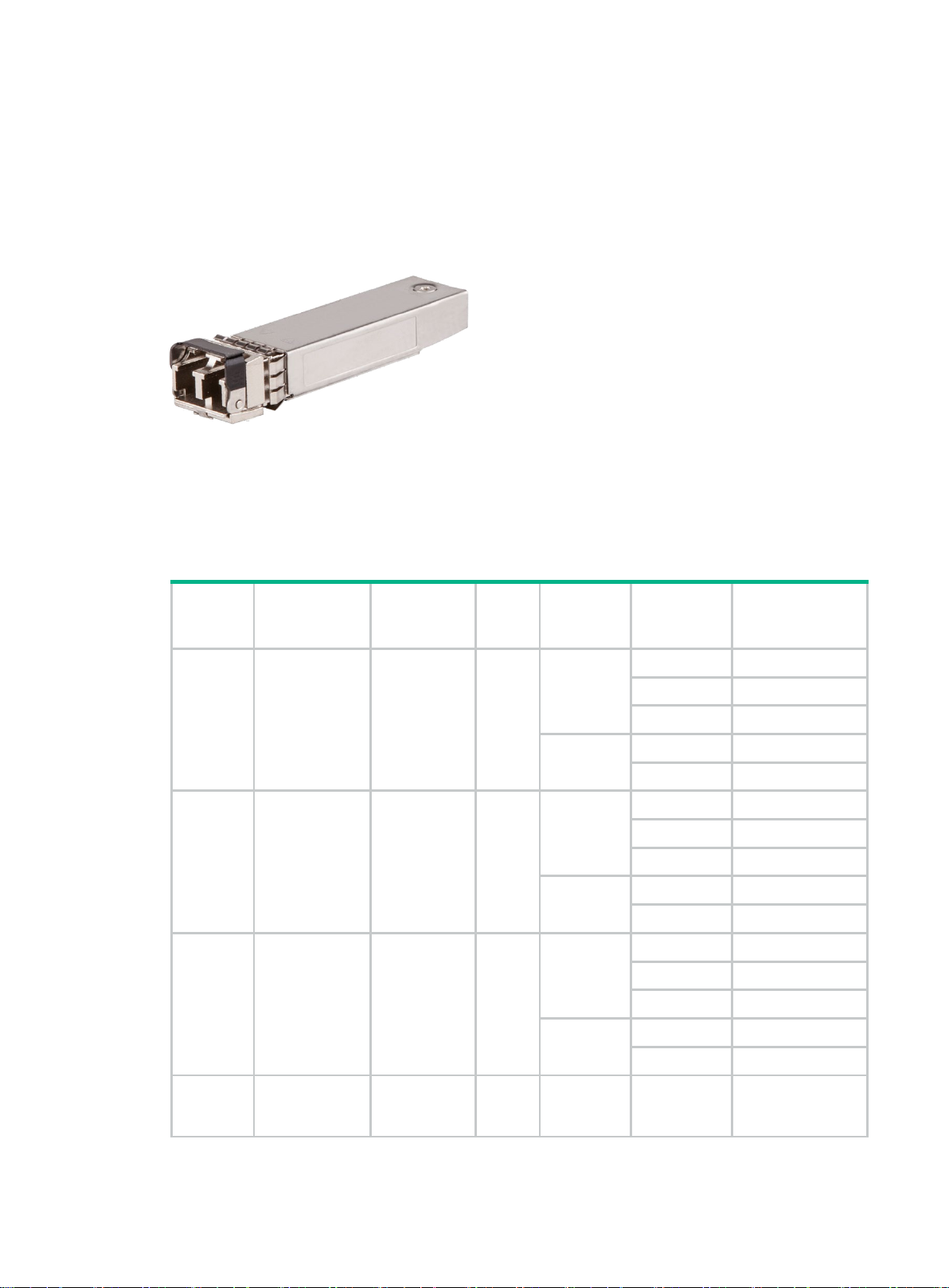
SFP+ copper cables
Product code
HPE description
Cable length
Data rate
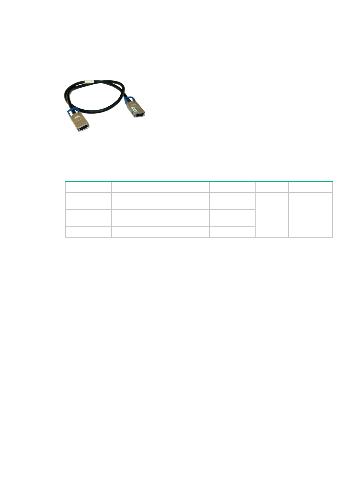
Figure 3 SFP+ copper cable
Models and specifications
Table 6 Specifications for SFP+ copper cables
JD095C
JD096B
JD096C
JD097B
JD097C
JG081C
JC784C
HPE X240 10G SFP+ SFP+ 0.65m Direct Attach
Copper Cable
HPE X240 10G SFP+ SFP+ 1.2m Direct Attach
Copper Cable
HPE X240 10G SFP+ SFP+ 1.2m Direct Attach
Copper Cable
HPE X240 10G SFP+ SFP+ 3m Direct Attach Copper
Cable
HPE X240 10G SFP+ SFP+ 3m Direct Attach Copper
Cable
HPE X240 10G SFP+ SFP+ 5m Direct Attach Copper
Cable
HPE X240 10G SFP+ SFP+ 7m Direct Attach Copper
Cable
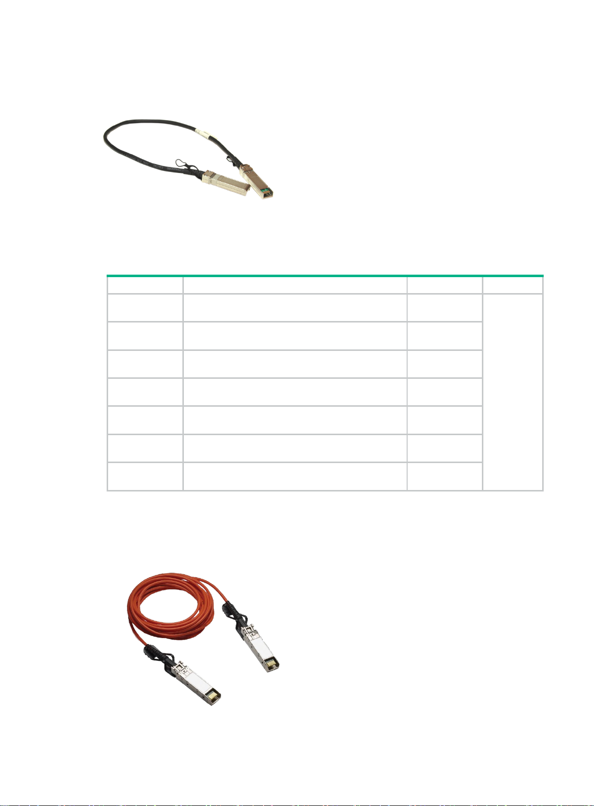
SFP+ active optical cables
Figure 4 SFP+ active optical cable
0.65 m (2.13 ft)
1.2 m (3.94 ft)
1.2 m (3.94 ft)
3 m (9.84 ft)
3 m (9.84 ft)
5 m (16.40 ft)
7 m (22.97 ft)
10.31 Gbps
7
Page 12

Models and specifications
code
Table 7 Specifications for SFP+ active optical cables
Product
JL290A HPE X2A0 10G SFP+ to SFP+ 7m Active Optical Cable 7 m (22.97 ft)
JL291A HPE X2A0 10G SFP+ to SFP+ 10m Active Optical Cable 10 m (32.81 ft)
JL292A HPE X2A0 10G SFP+ to SFP+ 20m Active Optical Cable 20 m (65.62 ft)
HPE description Cable length Data rate
10.31 Gbps
8
Page 13
XFP transceiver modules
(nm)
(MHz*km)
DWDM
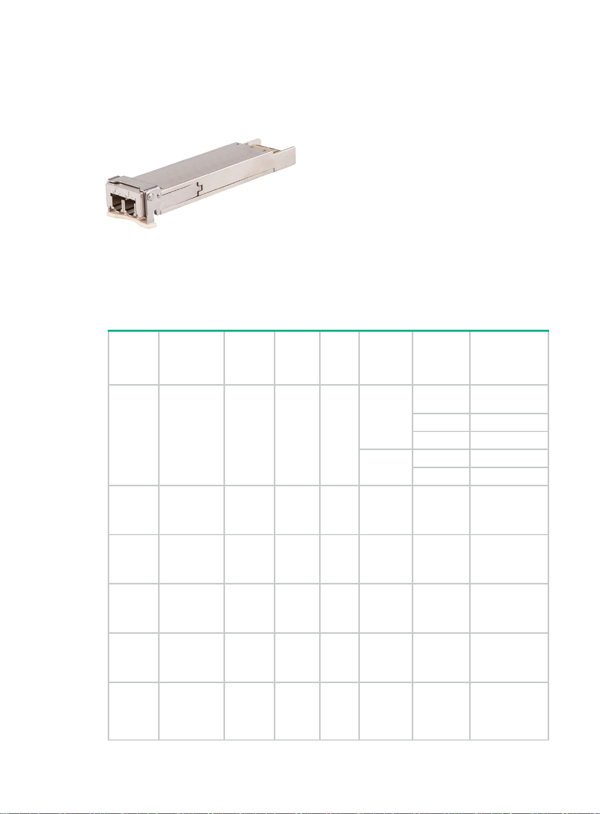
Figure 5 XFP transceiver module
Models and specifications
10-Gigabit XFP optical transceiver modules use LC connectors.
Table 8 Specifications for XFP transceiver modules (1)
Product
code
JD117B
JD108B
JD088A
JD121A
HPE
description
HPE X130
10G XFP LC
SR
Transceiver
HPE X130
10G XFP LC
LR 1310nm
Transceiver
HPE X135
10G XFP LC
LR
Transceiver
HPE X135
10G XFP LC
ER
Transceiver
Central
wavelength
850 10.31 MMF
1310 10.31 SMF 9/125 N/A
1310
1550
Data
rate
(Gbps)
9.95 to
11.3
9.95 to
10.7
Fiber
mode
SMF 9/125 N/A
SMF 9/125 N/A
Fiber
diameter
(µm)
50/125
62.5/125
Modal
bandwidth
2000
500 82 m (269.03 ft)
400 66 m (216.54 ft)
200 33 m (108.27 ft)
160 26 m (85.30 ft)
Transmission
distance
300 m (984.25
ft)
10 km (6.21
miles)
10 km (6.21
miles)
40 km (24.86
miles)
JD107A
JG226A
HPE X130
10G XFP LC
ZR 1550nm
Transceiver
HPE X180
10G XFP LC
LH 80km
1538.98nm
1550
1538.98
9.95 to
10.31
9.95 to
10.31
9
SMF 9/125 N/A
SMF 9/125 N/A
80 km (49.71
miles)
80 km (49.71
miles)
Page 14

Product
(nm)
(MHz*km)
Transceiver
Optical parameters (dBm)
power
code
JG227A
JG228A
JG229A
JG230A
HPE
description
HPE X180
10G XFP LC
LH 80km
1539.77nm
DWDM
Transceiver
HPE X180
10G XFP LC
LH 80km
1540.56nm
DWDM
Transceiver
HPE X180
10G XFP LC
LH 80km
1542.14nm
DWDM
Transceiver
HPE X180
10G XFP LC
LH 80km
1542.94nm
DWDM
Transceiver
Central
wavelength
1539.77
1540.56
1542.14
1542.94
Data
rate
(Gbps)
9.95 to
10.31
9.95 to
10.31
9.95 to
10.31
9.95 to
10.31
Fiber
mode
SMF 9/125 N/A
SMF 9/125 N/A
SMF 9/125 N/A
SMF 9/125 N/A
Fiber
diameter
(µm)
Modal
bandwidth
Transmission
distance
80 km (49.71
miles)
80 km (49.71
miles)
80 km (49.71
miles)
80 km (49.71
miles)
HPE X180
10G XFP LC
JG231A
JG232A
JG233A
LH 80km
1558.98nm
DWDM
Transceiver
HPE X180
10G XFP LC
LH 80km
1559.79nm
DWDM
Transceiver
HPE X180
10G XFP LC
LH 80km
1560.61nm
DWDM
Transceiver
1558.98
1559.79
1560.61
9.95 to
10.31
9.95 to
10.31
9.95 to
10.31
SMF 9/125 N/A
SMF 9/125 N/A
SMF 9/125 N/A
80 km (49.71
miles)
80 km (49.71
miles)
80 km (49.71
miles)
Table 9 Specifications for XFP transceiver modules (2)
Product code HPE description
JD117B HPE X130 10G XFP LC SR Transceiver –7.3 to –1.08 –9.9 to –1
Transmit
Receive power
JD108B
HPE X130 10G XFP LC LR 1310nm
Transceiver
10
–8.2 to +0.5 –14.4 to +0.5
Page 15

Product code HPE description
Optical parameters (dBm)
power
NOTE:
The 9/125µm single
conform to ITU
G.652.
JD088A HPE X135 10G XFP LC LR Transceiver –6 to –1 –10.3 to +0.5
JD121A HPE X135 10G XFP LC ER Transceiver –1 to +2 –14.1 to –1
Transmit
Receive power
JD107A
JG226A
JG227A
JG228A
JG229A
JG230A
JG231A
JG232A
JG233A
HPE X130 10G XFP LC ZR 1550nm
Transceiver
HPE X180 10G XFP LC LH 80km 1538.98nm
DWDM Transceiver
HPE X180 10G XFP LC LH 80km 1539.77nm
DWDM Transceiver
HPE X180 10G XFP LC LH 80km 1540.56nm
DWDM Transceiver
HPE X180 10G XFP LC LH 80km 1542.14nm
DWDM Transceiver
HPE X180 10G XFP LC LH 80km 1542.94nm
DWDM Transceiver
HPE X180 10G XFP LC LH 80km 1558.98nm
DWDM Transceiver
HPE X180 10G XFP LC LH 80km 1559.79nm
DWDM Transceiver
HPE X180 10G XFP LC LH 80km 1560.61nm
DWDM Transceiver
0 to +4 –24 to –7
–1 to +3 –24 to –7
–1 to +3 –24 to –7
–1 to +3 –24 to –7
–1 to +3 –24 to –7
–1 to +3 –24 to –7
–1 to +3 –24 to –7
–1 to +3 –24 to –7
–1 to +3 –24 to –7
-mode fibers used by transceiver modules JG226A through JG233A should
-T G.655, and those used by other transceiver modules should conform to ITU-T
11
Page 16
CX4 copper cables
Product code
HPE description
Cable length
Data rate
Description
Figure 6 CX4 copper cable
Models and specifications
Table 10 Specifications for CX4 copper cables
JD363B
JD364B
JD365A HPE X230 CX4 to CX4 3m Cable 3 m (9.84 ft)
HPE X230 Local Connect 50cm CX4
Cable
HPE X230 Local Connect 100cm
CX4 Cable
0.5 m (1.64 ft)
1 m (3.28 ft)
12 Gbps
Used for
interconnecting
deices, and
supports IRF
12
Page 17

10-Gigabit Ethernet transceiver modules
Product code
Transceiver module
Description
compatibility matrix
10-Gigabit Ethernet transceiver modules
Before you install, configure, or upgrade a device with HPE 10-Gigabit Ethernet transceiver modules,
always see the device's release notes for latest information. This compatibility matrix does not
replace or supersede the release notes.
Table 11 10 Gigabit Ethernet transceiver modules
SFP+
JD092B
JD093B
JD094B
JG234A
JG915A
JD097B
JD097C
JG081C
JD095B
JD095C
HPE X130 10G SFP+ LC SR
Transceiver
HPE X130 10G SFP+ LC LRM
Transceiver
HPE X130 10G SFP+ LC LR
Transceiver
HPE X130 10G SFP+ LC ER
40km Transceiver
HPE X130 10G SFP+ LC LH
80km Transceiver
HPE X240 10G SFP+ SFP+ 3m
Direct Attach Copper Cable
HPE X240 10G SFP+ SFP+ 3m
Direct Attach Copper Cable
HPE X240 SFP+ SFP+ 5m
Direct Attach Copper Cable
HPE X240 10G SFP+ SFP+
0.65m Direct Attach Copper
Cable
HPE X240 10G SFP+ SFP+
0.65m Direct Attach Copper
Cable
LSPM1SFPP,SFP+ Module(850nm,300m,LC)
LSPM3SFPP,SFP+ Module(1310nm,220m,LC)
LSPM2SFPP,SFP+ Module(1310nm,10km,LC)
LSTM2SFP,SFP+ Module,(1550nm,40km,LC)
LSTM3SFPPA,10G SFP+ Optical Transceiver
Module,(1550nm,80km,LC)
LSPM1STK,SFP+ Cable,3m
LSPM1STKD,SFP+ Cable,3m
LSRM1STKD,SFP+ Cable,5m
LSPM2STK,SFP+ Cable,0.65m
LSPM2STKD,SFP+ Cable,0.65m
JD096B
JD096C
JC784C
JL290A
JL291A
HPE X240 10G SFP+ SFP+
1.2m Direct Attach Copper
Cable
HPE X240 10G SFP+ SFP+
1.2m Direct Attach Copper
Cable
HPE X240 10G SFP+ SFP+ 7m
Direct Attach Copper Cable
HPE X2A0 10G SFP+ to SFP+
7m Active Optical Cable
HPE X2A0 10G SFP+ to SFP+
10m Active Optical Cable
13
LSPM3STK,SFP+ Cable,1.2m
LSPM3STKD,SFP+ Cable,1.2m
LSTM5STK7D,SFP+Cable,7m
LSWM2SFPPL,10G SFP+ to SFP+ Active Optical
Cable,7m
LSWM2SFPPM,10G SFP+ to SFP+ Active Optical
Cable,10m
Page 18
Product code
Transceiver module
Description
JL292A
release
support
version
HPE X2A0 10G SFP+ to SFP+
20m Active Optical Cable
LSWM2SFPPN,10G SFP+ to SFP+ Active Optical
Cable,20m
JL250A
HPE X130 10G SFP+ LC LH80
tunable Transceiver
LSXM1SFPP,10G SFP+ Optical Transceiver
Module,(Tunable,80km,LC)
Switching minimum software release requirements
HPE FlexFabric 12900 switch series minimum software version requirements
Minimum software
Switch or module Transceiver module (Product code)
HPE X130 10G SFP+ LC SR Xcvr (JD092B) YES R1005P07
HPE X130 10G SFP+ LC LR Xcvr (JD094B) YES R1005P07
HPE X130 10G SFP+ LC ER 40km Xcvr (JG234A) YES R1005P07
HPE X130 10G SFP+ LC LH 80km Xcvr (JG915A) YES R1005P07
DDM
Release
HPE FlexFabric
12900 48-port
10GbE SFP+ EA
Module (JG624A)
HPE FlexFabric
12900 48-port
1/10GbE SFP+ EC
Module (JG626A)
HPE X240 10G SFP+ SFP+ 3m Direct Attach Copper
Cable (JD097B)
HPE X240 10G SFP+ SFP+ 3m Direct Attach Copper
Cable (JD097C)
HPE X240 SFP+ SFP+ 5m Direct Attach Copper Cable
(JG081C)
HPE X240 10G SFP+ SFP+ 0.65m Direct Attach
Copper Cable (JD095B)
HPE X240 10G SFP+ SFP+ 0.65m Direct Attach
Copper Cable (JD095C)
HPE X240 10G SFP+ SFP+ 1.2m Direct Attach Copper
Cable (JD096B)
HPE X240 10G SFP+ SFP+ 1.2m Direct Attach Copper
Cable (JD096C)
HPE X2A0 10G SFP+ to SFP+ 7m Active Optical Cable
(JL290A)
HPE X2A0 10G SFP+ to SFP+ 10m Active Optical
Cable (JL291A)
HPE X2A0 10G SFP+ to SFP+ 20m Active Optical
Cable (JL292A)
HPE X130 10G SFP+ LC SR Xcvr (JD092B) YES R1005P07
HPE X130 10G SFP+ LC LR Xcvr (JD094B) YES R1005P07
HPE X130 10G SFP+ LC ER 40km Xcvr (JG234A) YES R1005P07
NO R1005P07
NO R1005P07
NO R1005P07
NO R1005P07
NO R1005P07
NO R1005P07
NO R1005P07
YES F1033L05
YES F1033L05
YES F1033L05
14
Page 19

Minimum software
release
support
version
Switch or module Transceiver module (Product code)
HPE X130 10G SFP+ LC LH 80km Xcvr (JG915A) YES R1005P10
HPE X240 10G SFP+ SFP+ 3m Direct Attach Copper
Cable (JD097B)
HPE X240 10G SFP+ SFP+ 3m Direct Attach Copper
Cable (JD097C)
HPE X240 SFP+ SFP+ 5m Direct Attach Copper Cable
(JG081C)
HPE X240 10G SFP+ SFP+ 0.65m Direct Attach
Copper Cable (JD095B)
HPE X240 10G SFP+ SFP+ 0.65m Direct Attach
Copper Cable (JD095C)
HPE X240 10G SFP+ SFP+ 1.2m Direct Attach Copper
Cable (JD096B)
HPE X240 10G SFP+ SFP+ 1.2m Direct Attach Copper
Cable (JD096C)
HPE X2A0 10G SFP+ to SFP+ 7m Active Optical Cable
(JL290A)
HPE X2A0 10G SFP+ to SFP+ 10m Active Optical
Cable (JL291A)
DDM
NO R1005P07
NO R1005P07
NO R1005P10
NO R1005P07
NO R1005P07
NO R1005P07
NO R1005P07
YES F1033L05
YES F1033L05
Release
HPE FlexFabric
12900 48-port GbE
SFP EB Module
(JG855A)
HPE X2A0 10G SFP+ to SFP+ 20m Active Optical
Cable (JL292A)
HPE X130 10G SFP+ LC SR Xcvr (JD092B) YES R1005P07
HPE X130 10G SFP+ LC LRM Xcvr (JD093B) YES R1005P07
HPE X130 10G SFP+ LC LR Xcvr (JD094B) YES R1005P07
HPE X130 10G SFP+ LC ER 40km Xcvr (JG234A) YES R1005P07
HPE X130 10G SFP+ LC LH 80km Xcvr (JG915A) YES R1005P07
HPE X240 10G SFP+ SFP+ 3m Direct Attach Copper
Cable (JD097B)
HPE X240 10G SFP+ SFP+ 3m Direct Attach Copper
Cable (JD097C)
HPE X240 SFP+ SFP+ 5m Direct Attach Copper Cable
(JG081C)
HPE X240 10G SFP+ SFP+ 0.65m Direct Attach
Copper Cable (JD095B)
HPE X240 10G SFP+ SFP+ 0.65m Direct Attach
Copper Cable (JD095C)
HPE X240 10G SFP+ SFP+ 1.2m Direct Attach Copper
Cable (JD096B)
HPE X240 10G SFP+ SFP+ 1.2m Direct Attach Copper
Cable (JD096C)
YES F1033L05
NO R1005P07
NO R1005P07
NO R1005P07
NO R1005P07
NO R1005P07
NO R1005P07
NO R1005P07
HPE X240 10G SFP+ SFP+ 7m Direct Attach Copper
Cable (JC784C)
15
NO R1005P07
Page 20

Minimum software
release
support
version
HPE X240 10G SFP+ SFP+ 1.2m Direct Attach Copper
Switch or module Transceiver module (Product code)
HPE X130 10G SFP+ LC SR Xcvr (JD092B) YES R1109
HPE X130 10G SFP+ LC LR Xcvr (JD094B) YES R1109
HPE X130 10G SFP+ LC ER 40km Xcvr (JG234A) YES R1109
HPE X130 10G SFP+ LC LH 80km Xcvr (JG915A) YES R1109
HPE X240 10G SFP+ SFP+ 3m Direct Attach Copper
Cable (JD097B)
HPE X240 10G SFP+ SFP+ 3m Direct Attach Copper
Cable (JD097C)
HPE X240 SFP+ SFP+ 5m Direct Attach Copper Cable
(JG081C)
HPE X240 10G SFP+ SFP+ 0.65m Direct Attach
HPE FlexFabric
12900 48-port
1/10GbE SFP+ FX
Module (JG888B)
Copper Cable (JD095B)
HPE X240 10G SFP+ SFP+ 0.65m Direct Attach
Copper Cable (JD095C)
HPE X240 10G SFP+ SFP+ 1.2m Direct Attach Copper
Cable (JD096B)
HPE X240 10G SFP+ SFP+ 1.2m Direct Attach Copper
Cable (JD096C)
DDM
NO R1109
NO R1109
NO R1109
NO R1109
NO R1109
NO R1109
NO R1109
Release
HP FlexFabric 12900
48-port 1/10GbE
SFP+ FC Module
(JG888A)
HPE X240 10G SFP+ SFP+ 7m Direct Attach Copper
Cable (JC784C)
HPE X2A0 10G SFP+ to SFP+ 7m Active Optical Cable
(JL290A)
HPE X2A0 10G SFP+ to SFP+ 10m Active Optical
Cable (JL291A)
HPE X2A0 10G SFP+ to SFP+ 20m Active Optical
Cable (JL292A)
HPE X130 10G SFP+ LC SR Xcvr (JD092B)
HPE X130 10G SFP+ LC LR Xcvr (JD094B)
HPE X130 10G SFP+ LC ER 40km Xcvr (JG234A)
HPE X130 10G SFP+ LC LH 80km Xcvr (JG915A)
HPE X240 10G SFP+ SFP+ 3m Direct Attach Copper
Cable (JD097B)
HPE X240 10G SFP+ SFP+ 3m Direct Attach Copper
Cable (JD097C)
HPE X240 SFP+ SFP+ 5m Direct Attach Copper Cable
(JG081C)
HPE X240 10G SFP+ SFP+ 0.65m Direct Attach
Copper Cable (JD095B)
NO R1109
YES R2138
YES R2138
YES R2138
YES R1109
YES R1109
YES R1109
YES R1109
NO R1109
NO R1109
NO R1109
NO R1109
HPE X240 10G SFP+ SFP+ 0.65m Direct Attach
Copper Cable (JD095C)
16
NO R1109
NO R1109
Page 21

Minimum software
release
support
version
Cable (JD096B)
NOTE:
For the HPE FlexFabric
10GBase
happens at auto-negotiation mode.
Switch or module Transceiver module (Product code)
HPE X240 10G SFP+ SFP+ 1.2m Direct Attach Copper
Cable (JD096C)
HPE X240 10G SFP+ SFP+ 7m Direct Attach Copper
Cable (JC784C)
HPE X2A0 10G SFP+ to SFP+ 7m Active Optical Cable
(JL290A)
HPE X2A0 10G SFP+ to SFP+ 10m Active Optical
Cable (JL291A)
HPE X2A0 10G SFP+ to SFP+ 20m Active Optical
Cable (JL292A)
HPE X130 10G SFP+ LC SR Xcvr (JD092B) YES R1135
HPE X130 10G SFP+ LC LR Xcvr (JD094B) YES R1135
HPE X130 10G SFP+ LC ER 40km Xcvr (JG234A) YES R1135
HPE X130 10G SFP+ LC LH 80km Xcvr (JG915A) YES R1135
HPE X240 10G SFP+ SFP+ 3m Direct Attach Copper
Cable (JD097B)
DDM
NO R1109
NO R1109
YES R2138
YES R2138
YES R2138
NO
Release
R1135
HPE FlexFabric
12900 48-port
1/10GbE SFP+ FE
Module (JH249A)
-T SFP+ Transceiver (813874-B21) only add ports are supported and link-up only
HPE X240 10G SFP+ SFP+ 3m Direct Attach Copper
Cable (JD097C)
HPE X240 SFP+ SFP+ 5m Direct Attach Copper Cable
(JG081C)
HPE X240 10G SFP+ SFP+ 0.65m Direct Attach
Copper Cable (JD095B)
HPE X240 10G SFP+ SFP+ 0.65m Direct Attach
Copper Cable (JD095C)
HPE X2A0 10G SFP+ to SFP+ 7m Active Optical Cable
(JL290A)
HPE X2A0 10G SFP+ to SFP+ 10m Active Optical
Cable (JL291A)
HPE X2A0 10G SFP+ to SFP+ 20m Active Optical
Cable (JL292A)
HPE 10GBase-T SFP+ Transceiver (813874-B21) NO R2710
NO
NO
NO
NO
YES R2138
YES R2138
YES R2138
R1135
R1135
R1135
R1135
12900 48-port 1/10GbE SFP+ FE Module (JH249A), when using the HPE
17
Page 22

HPE FlexFabric 12900E switch series minimum software
release
support
version
version requirements
Minimum software
Switch or module Transceiver module (Product code)
HPE X130 10G SFP+ LC SR Xcvr (JD092B) YES R2606
HPE X130 10G SFP+ LC LR Xcvr (JD094B) YES R2606
HPE X130 10G SFP+ LC ER 40km Xcvr (JG234A) YES R2606
HPE X130 10G SFP+ LC LH 80km Xcvr (JG915A) YES R2606
HPE X130 10G SFP+ LC LH80 tunable Xcvr (JL250A) YES R2609
HPE X240 10G SFP+ SFP+ 3m Direct Attach Copper
Cable (JD097B)
HPE X240 10G SFP+ SFP+ 3m Direct Attach Copper
Cable (JD097C)
HPE X240 SFP+ SFP+ 5m Direct Attach Copper Cable
(JG081C)
HPE FlexFabric
12900E 48-port
1/10GbE SFP+ 2port 100GbE
QSFP28 HB Module
(JH360A)
HPE X240 10G SFP+ SFP+ 0.65m Direct Attach
Copper Cable (JD095B)
HPE X240 10G SFP+ SFP+ 0.65m Direct Attach
Copper Cable (JD095C)
HPE X240 10G SFP+ SFP+ 1.2m Direct Attach Copper
Cable (JD096B)
DDM
NO
NO
NO
NO
NO
NO
Release
R2606
R2606
R2606
R2606
R2606
R2606
HPE FlexFabric
12900E 24p 10G/2p
40G HB 59xx Slot
Module (JH953A)
HPE X240 10G SFP+ SFP+ 1.2m Direct Attach Copper
Cable (JD096C)
HPE X240 10G SFP+ SFP+ 7m Direct Attach Copper
Cable (JC784C)
HPE X2A0 10G SFP+ to SFP+ 7m Active Optical Cable
(JL290A)
HPE X2A0 10G SFP+ to SFP+ 10m Active Optical
Cable (JL291A)
HPE X2A0 10G SFP+ to SFP+ 20m Active Optical
Cable (JL292A)
HPE 10GBase-T SFP+ Transceiver (813874-B21) NO R2609
HPE X130 10G SFP+ LC SR Xcvr (JD092B) YES R2706P01
HPE X130 10G SFP+ LC LR Xcvr (JD094B) YES R2706P01
HPE X130 10G SFP+ LC ER 40km Xcvr (JG234A) YES R2706P01
HPE X130 10G SFP+ LC LH 80km Xcvr (JG915A) YES R2706P01
HPE X130 10G SFP+ LC LH80 tunable Xcvr (JL250A) YES R2706P01
HPE X240 10G SFP+ SFP+ 3m Direct Attach Copper
Cable (JD097B)
HPE X240 10G SFP+ SFP+ 3m Direct Attach Copper
Cable (JD097C)
NO
NO
YES
YES
YES
NO
NO
R2606
R2606
R2606
R2606
R2606
R2706P01
R2706P01
18
Page 23

Minimum software
release
support
version
Switch or module Transceiver module (Product code)
HPE X240 SFP+ SFP+ 5m Direct Attach Copper Cable
(JG081C)
HPE X240 10G SFP+ SFP+ 0.65m Direct Attach
Copper Cable (JD095B)
HPE X240 10G SFP+ SFP+ 0.65m Direct Attach
Copper Cable (JD095C)
HPE X240 10G SFP+ SFP+ 1.2m Direct Attach Copper
Cable (JD096B)
HPE X240 10G SFP+ SFP+ 1.2m Direct Attach Copper
Cable (JD096C)
HPE X240 10G SFP+ SFP+ 7m Direct Attach Copper
Cable (JC784C)
HPE X130 10G SFP+ LC SR Xcvr (JD092B) YES R2710
HPE X130 10G SFP+ LC LR Xcvr (JD094B) YES R2710
HPE X130 10G SFP+ LC ER 40km Xcvr (JG234A) YES R2710
HPE X130 10G SFP+ LC LH 80km Xcvr (JG915A) YES R2710
HPE X130 10G SFP+ LC LH80 tunable Xcvr (JL250A) YES R2710
DDM
NO
NO
NO
NO
NO
NO
Release
R2706P01
R2706P01
R2706P01
R2706P01
R2706P01
R2706P01
HPE FlexFabric
12900E 24p 10G/4p
100G HD 59xx Slot
Module(JH954A)
HPE FlexFabric
12900E 48-port
10GbE SFP+ HF
Module (JQ061A)
HPE X240 10G SFP+ SFP+ 3m Direct Attach Copper
Cable (JD097C)
HPE X240 SFP+ SFP+ 5m Direct Attach Copper Cable
(JG081C)
HPE X240 10G SFP+ SFP+ 0.65m Direct Attach
Copper Cable (JD095B)
HPE X240 10G SFP+ SFP+ 0.65m Direct Attach
Copper Cable (JD095C)
HPE X240 10G SFP+ SFP+ 1.2m Direct Attach Copper
Cable (JD096B)
HPE X240 10G SFP+ SFP+ 1.2m Direct Attach Copper
Cable (JD096C)
HPE X240 10G SFP+ SFP+ 7m Direct Attach Copper
Cable (JC784C)
HPE X130 10G SFP+ LC SR Xcvr (JD092B) YES R2706P01
HPE X130 10G SFP+ LC LR Xcvr (JD094B) YES R2706P01
HPE X130 10G SFP+ LC ER 40km Xcvr (JG234A) YES R2706P01
HPE X130 10G SFP+ LC LH 80km Xcvr (JG915A) YES R2706P01
HPE X240 10G SFP+ SFP+ 3m Direct Attach Copper
Cable (JD097C)
HPE X240 SFP+ SFP+ 5m Direct Attach Copper Cable
(JG081C)
NO R2710
NO R2710
NO R2710
NO R2710
NO R2710
NO R2710
NO R2710
NO
NO
R2706P01
R2706P01
HPE X240 10G SFP+ SFP+ 0.65m Direct Attach
Copper Cable (JD095B)
19
NO
R2706P01
Page 24

Minimum software
release
support
version
NOTE:
For the HPE
(
the HPE 10GBase
only happens at auto-negotiation mode.
release
support
version
Switch or module Transceiver module (Product code)
DDM
HPE X240 10G SFP+ SFP+ 0.65m Direct Attach
Copper Cable (JD095C)
HPE X240 10G SFP+ SFP+ 1.2m Direct Attach Copper
Cable (JD096B)
HPE X240 10G SFP+ SFP+ 1.2m Direct Attach Copper
Cable (JD096C)
HPE X240 10G SFP+ SFP+ 7m Direct Attach Copper
Cable (JC784C)
HPE 10GBase-T SFP+ Transceiver (813874-B21) NO R2609
NO
NO
NO
NO
Release
R2706P01
R2706P01
R2706P01
R2706P01
FlexFabric 12900E 48-port 1/10GbE SFP+ 2-port 100GbE QSFP28 HB Module
JH360A) and HPE FlexFabric 12900E 48-port 10GbE SFP+ HF Module (JQ061A), when using
-T SFP+ Transceiver (813874-B21) only add ports are supported and link-up
HPE FlexFabric 11900 switch series minimum software version requirements
Switch or module Transceiver module (Product code)
HPE X130 10G SFP+ LC SR Xcvr (JD092B) YES B7143
HPE X130 10G SFP+ LC LRM Xcvr (JD093B) YES B7143
HPE X130 10G SFP+ LC LR Xcvr (JD094B) YES B7148
HPE X130 10G SFP+ LC ER 40km Xcvr (JG234A) YES B7143
HPE X130 10G SFP+ LC LH 80km Xcvr (JG915A) YES B7143
HPE X130 10G SFP+ LC LH80 tunable Xcvr (JL250A) YES R7180
HPE X240 10G SFP+ SFP+ 3m Direct Attach Copper
HP FlexFabric 11900
32-port 10GbE SFP+
SF Module (JG611A)
Cable (JD097B)
HPE X240 10G SFP+ SFP+ 3m Direct Attach Copper
Cable (JD097C)
HPE X240 SFP+ SFP+ 5m Direct Attach Copper Cable
(JG081C)
HPE X240 10G SFP+ SFP+ 1.2m Direct Attach Copper
Cable (JD096B)
HPE X240 10G SFP+ SFP+ 1.2m Direct Attach Copper
Cable (JD096C)
Minimum software
DDM
NO B7143
NO B7143
NO B7143
NO B7143
NO B7143
Release
HPE X240 10G SFP+ SFP+ 7m Direct Attach Copper
Cable (JC784C)
20
NO B7143
Page 25

Minimum software
release
support
version
release
support
version
Switch or module Transceiver module (Product code)
HP FlexFabric 11900
48-port 10GbE SFP+
SF Module (JG612A)
DDM
HPE X130 10G SFP+ LC SR Xcvr (JD092B) YES B7143
HPE X130 10G SFP+ LC LR Xcvr (JD094B) YES B7148
HPE X130 10G SFP+ LC ER 40km Xcvr (JG234A) YES B7143
HPE X130 10G SFP+ LC LH 80km Xcvr (JG915A) YES B7143
HPE X130 10G SFP+ LC LH80 tunable Xcvr (JL250A) YES R7180
HPE X240 10G SFP+ SFP+ 3m Direct Attach Copper
Cable (JD097B)
HPE X240 10G SFP+ SFP+ 3m Direct Attach Copper
Cable (JD097C)
HPE X240 SFP+ SFP+ 5m Direct Attach Copper Cable
(JG081C)
HPE X240 10G SFP+ SFP+ 1.2m Direct Attach Copper
Cable (JD096B)
HPE X240 10G SFP+ SFP+ 1.2m Direct Attach Copper
Cable (JD096C)
NO B7143
NO B7143
NO B7143
NO B7143
NO B7143
Release
HPE FlexFabric 10500 switch series minimum software version requirements
Switch or module Transceiver module (Product code)
HPE X130 10G SFP+ LC SR Xcvr (JD092B) YES B7143
HPE X130 10G SFP+ LC LRM Xcvr (JD093B) YES B7143
HPE X130 10G SFP+ LC LR Xcvr (JD094B) YES B7148
HPE X130 10G SFP+ LC ER 40km Xcvr (JG234A) YES B7143
HPE X130 10G SFP+ LC LH 80km Xcvr (JG915A) YES B7143
HPE X130 10G SFP+ LC LH80 tunable Xcvr (JL250A) YES R7180
HP A10500 16-port
10-GbE SFP+ SC
Module (JC628A)
HPE X240 10G SFP+ SFP+ 3m Direct Attach Copper
Cable (JD097B)
HPE X240 10G SFP+ SFP+ 3m Direct Attach Copper
Cable (JD097C)
HPE X240 SFP+ SFP+ 5m Direct Attach Copper Cable
(JG081C)
HPE X240 10G SFP+ SFP+ 1.2m Direct Attach Copper
Cable (JD096B)
Minimum software
DDM
NO B7143
NO B7143
NO B7143
NO B7143
Release
HPE X240 10G SFP+ SFP+ 1.2m Direct Attach Copper
Cable (JD096C)
21
NO B7143
Page 26

Minimum software
release
support
version
Switch or module Transceiver module (Product code)
HPE X240 10G SFP+ SFP+ 7m Direct Attach Copper
HP A10500 8-port
10-GbE SFP+ EB
Module (JC629A)
Cable (JC784C)
HPE X130 10G SFP+ LC SR Xcvr (JD092B) YES B7143
HPE X130 10G SFP+ LC LRM Xcvr (JD093B) YES B7143
HPE X130 10G SFP+ LC LR Xcvr (JD094B) YES B7148
HPE X130 10G SFP+ LC ER 40km Xcvr (JG234A) YES B7143
HPE X130 10G SFP+ LC LH 80km Xcvr (JG915A) YES B7143
HPE X130 10G SFP+ LC LH80 tunable Xcvr (JL250A) YES R7180
HPE X240 10G SFP+ SFP+ 3m Direct Attach Copper
Cable (JD097B)
HPE X240 10G SFP+ SFP+ 3m Direct Attach Copper
Cable (JD097C)
HPE X240 SFP+ SFP+ 5m Direct Attach Copper Cable
(JG081C)
HPE X240 10G SFP+ SFP+ 1.2m Direct Attach Copper
Cable (JD096B)
HPE X240 10G SFP+ SFP+ 1.2m Direct Attach Copper
Cable (JD096C)
DDM
NO B7143
NO B7143
NO B7143
NO B7143
NO B7143
NO B7143
Release
HP A10500 8-port
10-GbE SFP+ EA
Module (JC630A)
HPE X240 10G SFP+ SFP+ 7m Direct Attach Copper
Cable (JC784C)
HPE X130 10G SFP+ LC SR Xcvr (JD092B) YES B7143
HPE X130 10G SFP+ LC LRM Xcvr (JD093B) YES B7143
HPE X130 10G SFP+ LC LR Xcvr (JD094B) YES B7148
HPE X130 10G SFP+ LC ER 40km Xcvr (JG234A) YES B7143
HPE X130 10G SFP+ LC LH 80km Xcvr (JG915A) YES B7143
HPE X130 10G SFP+ LC LH80 tunable Xcvr (JL250A) YES R7180
HPE X240 10G SFP+ SFP+ 3m Direct Attach Copper
Cable (JD097B)
HPE X240 10G SFP+ SFP+ 3m Direct Attach Copper
Cable (JD097C)
HPE X240 SFP+ SFP+ 5m Direct Attach Copper Cable
(JG081C)
HPE X240 10G SFP+ SFP+ 1.2m Direct Attach Copper
Cable (JD096B)
HPE X240 10G SFP+ SFP+ 1.2m Direct Attach Copper
Cable (JD096C)
HPE X240 10G SFP+ SFP+ 7m Direct Attach Copper
Cable (JC784C)
NO B7143
NO B7143
NO B7143
NO B7143
NO B7143
NO B7143
NO B7143
22
Page 27

Minimum software
release
support
version
Switch or module Transceiver module (Product code)
HPE X130 10G SFP+ LC SR Xcvr (JD092B) YES B7143
HPE X130 10G SFP+ LC LRM Xcvr (JD093B) YES B7143
HPE X130 10G SFP+ LC LR Xcvr (JD094B) YES B7148
HPE X130 10G SFP+ LC ER 40km Xcvr (JG234A) YES B7143
HPE X130 10G SFP+ LC LH 80km Xcvr (JG915A) YES B7143
HPE X130 10G SFP+ LC LH80 tunable Xcvr (JL250A) YES R7180
HPE X240 10G SFP+ SFP+ 3m Direct Attach Copper
HP A10500 8-port
10-GbE SFP+ SE
Module (JC631A)
Cable (JD097B)
HPE X240 10G SFP+ SFP+ 3m Direct Attach Copper
Cable (JD097C)
HPE X240 SFP+ SFP+ 5m Direct Attach Copper Cable
(JG081C)
HPE X240 10G SFP+ SFP+ 1.2m Direct Attach Copper
Cable (JD096B)
HPE X240 10G SFP+ SFP+ 1.2m Direct Attach Copper
Cable (JD096C)
HPE X240 10G SFP+ SFP+ 7m Direct Attach Copper
Cable (JC784C)
DDM
NO B7143
NO B7143
NO B7143
NO B7143
NO B7143
NO B7143
Release
HPE FlexNetwork
10500 32-port
10GbE SFP+ SF
Module (JC755A)
HPE X130 10G SFP+ LC SR Xcvr (JD092B)
HPE X130 10G SFP+ LC LRM Xcvr (JD093B)
HPE X130 10G SFP+ LC LR Xcvr (JD094B)
HPE X130 10G SFP+ LC ER 40km Xcvr (JG234A)
HPE X130 10G SFP+ LC LH 80km Xcvr (JG915A)
HPE X130 10G SFP+ LC LH80 tunable Xcvr (JL250A) YES R7180
HPE X240 10G SFP+ SFP+ 3m Direct Attach Copper
Cable (JD097B)
HPE X240 10G SFP+ SFP+ 3m Direct Attach Copper
Cable (JD097C)
HPE X240 SFP+ SFP+ 5m Direct Attach Copper Cable
(JG081C)
HPE X240 10G SFP+ SFP+ 1.2m Direct Attach Copper
Cable (JD096B)
HPE X240 10G SFP+ SFP+ 1.2m Direct Attach Copper
Cable (JD096C)
HPE X240 10G SFP+ SFP+ 7m Direct Attach Copper
Cable (JC784C)
YES B7143
YES B7143
YES B7148
YES B7143
YES B7143
NO B7143
NO B7143
NO B7143
NO B7143
NO B7143
NO B7143
23
Page 28

Minimum software
release
support
version
Switch or module Transceiver module (Product code)
HPE X130 10G SFP+ LC SR Xcvr (JD092B) YES B7143
HPE X130 10G SFP+ LC LR Xcvr (JD094B) YES B7148
HPE X130 10G SFP+ LC ER 40km Xcvr (JG234A) YES B7143
HPE X130 10G SFP+ LC LH 80km Xcvr (JG915A) YES B7143
HPE X130 10G SFP+ LC LH80 tunable Xcvr (JL250A) YES R7180
HPE FlexNetwork
10500 48-port
10GbE SFP+ SF
Module (JC756A)
HPE FlexNetwork
10500 24-port
1/10GbE SFP+ EC
Module (JH194A)
HPE X240 10G SFP+ SFP+ 3m Direct Attach Copper
Cable (JD097B)
HPE X240 10G SFP+ SFP+ 3m Direct Attach Copper
Cable (JD097C)
HPE X240 SFP+ SFP+ 5m Direct Attach Copper Cable
(JG081C)
HPE X240 10G SFP+ SFP+ 1.2m Direct Attach Copper
Cable (JD096B)
HPE X240 10G SFP+ SFP+ 1.2m Direct Attach Copper
Cable (JD096C)
HPE X130 10G SFP+ LC SR Xcvr (JD092B) YES B7143
HPE X130 10G SFP+ LC LR Xcvr (JD094B) YES B7148
HPE X130 10G SFP+ LC LH 80km Xcvr (JG915A) YES B7143
HPE X130 10G SFP+ LC LH80 tunable Xcvr (JL250A) YES R7180
DDM
NO B7143
NO B7143
NO B7143
NO B7143
NO B7143
Release
HPE 10500 24-Port
GbE/10GbE SFP+
EC TAA-compliant
Module (JH202A)
HPE FlexNetwork
10500 44-port GbE
SFP/4-port 10GbE
SFP+ SE Module
(JH191A)
HPE X130 10G SFP+ LC SR Xcvr (JD092B) YES B7143
HPE X130 10G SFP+ LC LR Xcvr (JD094B) YES B7148
HPE X130 10G SFP+ LC LH 80km Xcvr (JG915A) YES B7143
HPE X130 10G SFP+ LC LH80 tunable Xcvr (JL250A) YES R7180
HPE X130 10G SFP+ LC SR Xcvr (JD092B) YES B7143
HPE X130 10G SFP+ LC LR Xcvr (JD094B) YES B7148
HPE X130 10G SFP+ LC ER 40km Xcvr (JG234A) YES B7143
HPE X130 10G SFP+ LC LH 80km Xcvr (JG915A) YES B7143
HPE X130 10G SFP+ LC LH80 tunable Xcvr (JL250A) YES R7180
HPE X240 10G SFP+ SFP+ 3m Direct Attach Copper
Cable (JD097B)
HPE X240 10G SFP+ SFP+ 3m Direct Attach Copper
Cable (JD097C)
HPE X240 10G SFP+ SFP+ 0.65m Direct Attach
Copper Cable (JD095C)
HPE X240 10G SFP+ SFP+ 1.2m Direct Attach Copper
Cable (JD096B)
HPE X240 10G SFP+ SFP+ 1.2m Direct Attach Copper
Cable (JD096C)
NO B7143
NO B7143
NO B7143
NO B7143
NO B7143
24
Page 29

Minimum software
release
support
version
Switch or module Transceiver module (Product code)
HPE X130 10G SFP+ LC SR Xcvr (JD092B) YES B7143
HPE X130 10G SFP+ LC LR Xcvr (JD094B) YES B7148
HPE X130 10G SFP+ LC ER 40km Xcvr (JG234A) YES B7143
HPE X130 10G SFP+ LC LH 80km Xcvr (JG915A) YES B7143
HPE X130 10G SFP+ LC LH80 tunable Xcvr (JL250A) YES R7180
HPE 10500 44-Port
GbE SFP/4-Port
10GbE SFP+ SE
TAA-compliant
Module (JH199A)
HPE X240 10G SFP+ SFP+ 3m Direct Attach Copper
Cable (JD097B)
HPE X240 10G SFP+ SFP+ 3m Direct Attach Copper
Cable (JD097C)
HPE X240 10G SFP+ SFP+ 0.65m Direct Attach
Copper Cable (JD095C)
HPE X240 10G SFP+ SFP+ 1.2m Direct Attach Copper
Cable (JD096B)
HPE X240 10G SFP+ SFP+ 1.2m Direct Attach Copper
Cable (JD096C)
HPE X130 10G SFP+ LC SR Xcvr (JD092B) YES B7143
HPE X130 10G SFP+ LC LR Xcvr (JD094B) YES B7148
DDM
NO B7143
NO B7143
NO B7143
NO B7143
NO B7143
Release
HPE FlexNetwork
10500 16-port
1/10GbE SFP+ SF
Module (JH193A)
HPE 10500 16-Port
GbE/10GbE SFP+
SF TAA-compliant
Module (JH201A)
HPE X130 10G SFP+ LC ER 40km Xcvr (JG234A) YES B7143
HPE X130 10G SFP+ LC LH 80km Xcvr (JG915A) YES B7143
HPE X130 10G SFP+ LC LH80 tunable Xcvr (JL250A) YES R7180
HPE X240 10G SFP+ SFP+ 3m Direct Attach Copper
Cable (JD097B)
HPE X240 10G SFP+ SFP+ 3m Direct Attach Copper
Cable (JD097C)
HPE X240 SFP+ SFP+ 5m Direct Attach Copper Cable
(JG081C)
HPE X240 10G SFP+ SFP+ 0.65m Direct Attach
Copper Cable (JD095C)
HPE X240 10G SFP+ SFP+ 1.2m Direct Attach Copper
Cable (JD096B)
HPE X240 10G SFP+ SFP+ 1.2m Direct Attach Copper
Cable (JD096C)
HPE X240 10G SFP+ SFP+ 7m Direct Attach Copper
Cable (JC784C)
HPE X130 10G SFP+ LC SR Xcvr (JD092B) YES B7143
HPE X130 10G SFP+ LC LR Xcvr (JD094B) YES B7148
HPE X130 10G SFP+ LC ER 40km Xcvr (JG234A) YES B7143
HPE X130 10G SFP+ LC LH 80km Xcvr (JG915A) YES B7143
NO B7143
NO B7143
NO B7143
NO B7143
NO B7143
NO B7143
NO B7143
HPE X130 10G SFP+ LC LH80 tunable Xcvr (JL250A) YES R7180
25
Page 30

Minimum software
release
support
version
HPE X240 SFP+ SFP+ 5m Direct Attach Copper Cable
Switch or module Transceiver module (Product code)
HPE X240 10G SFP+ SFP+ 3m Direct Attach Copper
Cable (JD097B)
HPE X240 10G SFP+ SFP+ 3m Direct Attach Copper
Cable (JD097C)
HPE X240 SFP+ SFP+ 5m Direct Attach Copper Cable
(JG081C)
HPE X240 10G SFP+ SFP+ 0.65m Direct Attach
Copper Cable (JD095C)
HPE X240 10G SFP+ SFP+ 1.2m Direct Attach Copper
Cable (JD096B)
HPE X240 10G SFP+ SFP+ 1.2m Direct Attach Copper
Cable (JD096C)
HPE X240 10G SFP+ SFP+ 7m Direct Attach Copper
Cable (JC784C)
HPE X130 10G SFP+ LC SR Xcvr (JD092B) YES B7143
HPE X130 10G SFP+ LC LR Xcvr (JD094B) YES B7148
HPE X130 10G SFP+ LC ER 40km Xcvr (JG234A) YES B7143
HPE X130 10G SFP+ LC LH 80km Xcvr (JG915A) YES B7143
DDM
NO B7143
NO B7143
NO B7143
NO B7143
NO B7143
NO B7143
NO B7143
Release
HPE FlexNetwork
10500 48-port
1/10GbE SFP+ SG
Module (JH197A)
HPE 10500 48-Port
GbE/10GbE SFP+
SG TAA-compliant
Module (JH205A)
HPE X130 10G SFP+ LC LH80 tunable Xcvr (JL250A) YES R7180
HPE X240 10G SFP+ SFP+ 3m Direct Attach Copper
Cable (JD097B)
HPE X240 10G SFP+ SFP+ 3m Direct Attach Copper
Cable (JD097C)
HPE X240 SFP+ SFP+ 5m Direct Attach Copper Cable
(JG081C)
HPE X240 10G SFP+ SFP+ 0.65m Direct Attach
Copper Cable (JD095C)
HPE X240 10G SFP+ SFP+ 1.2m Direct Attach Copper
Cable (JD096B)
HPE X240 10G SFP+ SFP+ 1.2m Direct Attach Copper
Cable (JD096C)
HPE X130 10G SFP+ LC SR Xcvr (JD092B) YES B7143
HPE X130 10G SFP+ LC LR Xcvr (JD094B) YES B7148
HPE X130 10G SFP+ LC ER 40km Xcvr (JG234A) YES B7143
HPE X130 10G SFP+ LC LH 80km Xcvr (JG915A) YES B7143
HPE X130 10G SFP+ LC LH80 tunable Xcvr (JL250A) YES R7180
HPE X240 10G SFP+ SFP+ 3m Direct Attach Copper
Cable (JD097B)
NO B7143
NO B7143
NO B7143
NO B7143
NO B7143
NO B7143
NO B7143
HPE X240 10G SFP+ SFP+ 3m Direct Attach Copper
Cable (JD097C)
NO B7143
NO B7143
26
Page 31

Minimum software
release
support
version
(JG081C)
HPE X240 10G SFP+ SFP+ 1.2m Direct Attach Copper
Switch or module Transceiver module (Product code)
HPE X240 10G SFP+ SFP+ 0.65m Direct Attach
Copper Cable (JD095C)
HPE X240 10G SFP+ SFP+ 1.2m Direct Attach Copper
Cable (JD096B)
HPE X240 10G SFP+ SFP+ 1.2m Direct Attach Copper
Cable (JD096C)
HPE X130 10G SFP+ LC SR Xcvr (JD092B) YES B7143
HPE X130 10G SFP+ LC LRM Xcvr (JD093B) YES B7143
HPE X130 10G SFP+ LC LR Xcvr (JD094B) YES B7148
HPE X130 10G SFP+ LC ER 40km Xcvr (JG234A) YES B7143
HPE X130 10G SFP+ LC LH 80km Xcvr (JG915A) YES B7143
HPE X130 10G SFP+ LC LH80 tunable Xcvr (JL250A) YES R7180
HP 10500 8-port
10GbE SFP+ EB
TAA-compliant
Module (JG387A)
HPE X240 10G SFP+ SFP+ 3m Direct Attach Copper
Cable (JD097B)
HPE X240 10G SFP+ SFP+ 3m Direct Attach Copper
Cable (JD097C)
DDM
NO B7143
NO B7143
NO B7143
NO B7143
NO B7143
Release
HP 10500 8-port
10GbE SFP+ EA
TAA-compliant
Module (JG388A)
HPE X240 SFP+ SFP+ 5m Direct Attach Copper Cable
(JG081C)
HPE X240 10G SFP+ SFP+ 1.2m Direct Attach Copper
Cable (JD096B)
HPE X240 10G SFP+ SFP+ 1.2m Direct Attach Copper
Cable (JD096C)
HPE X240 10G SFP+ SFP+ 7m Direct Attach Copper
Cable (JC784C)
HPE X130 10G SFP+ LC SR Xcvr (JD092B) YES B7143
HPE X130 10G SFP+ LC LRM Xcvr (JD093B) YES B7143
HPE X130 10G SFP+ LC LR Xcvr (JD094B) YES B7148
HPE X130 10G SFP+ LC ER 40km Xcvr (JG234A) YES B7143
HPE X130 10G SFP+ LC LH 80km Xcvr (JG915A) YES B7143
HPE X130 10G SFP+ LC LH80 tunable Xcvr (JL250A) YES R7180
HPE X240 10G SFP+ SFP+ 3m Direct Attach Copper
Cable (JD097B)
HPE X240 10G SFP+ SFP+ 3m Direct Attach Copper
Cable (JD097C)
HPE X240 SFP+ SFP+ 5m Direct Attach Copper Cable
(JG081C)
NO B7143
NO B7143
NO B7143
NO B7143
NO B7143
NO B7143
NO B7143
HPE X240 10G SFP+ SFP+ 1.2m Direct Attach Copper
Cable (JD096B)
NO B7143
NO B7143
27
Page 32

Minimum software
release
support
version
Cable (JD096C)
Switch or module Transceiver module (Product code)
HPE X240 10G SFP+ SFP+ 7m Direct Attach Copper
Cable (JC784C)
HPE X130 10G SFP+ LC SR Xcvr (JD092B) YES B7143
HPE X130 10G SFP+ LC LRM Xcvr (JD093B) YES B7143
HPE X130 10G SFP+ LC LR Xcvr (JD094B) YES B7148
HPE X130 10G SFP+ LC ER 40km Xcvr (JG234A) YES B7143
HPE X130 10G SFP+ LC LH 80km Xcvr (JG915A) YES B7143
HPE X130 10G SFP+ LC LH80 tunable Xcvr (JL250A) YES R7180
HP 10500 8-port
10GbE SFP+ SE
TAA-compliant
Module (JG389A)
HPE X240 10G SFP+ SFP+ 3m Direct Attach Copper
Cable (JD097B)
HPE X240 10G SFP+ SFP+ 3m Direct Attach Copper
Cable (JD097C)
HPE X240 SFP+ SFP+ 5m Direct Attach Copper Cable
(JG081C)
HPE X240 10G SFP+ SFP+ 1.2m Direct Attach Copper
Cable (JD096B)
DDM
NO B7143
NO B7143
NO B7143
NO B7143
NO B7143
Release
HPE FlexNetwork
10500 32-port
10GbE SFP+ SF
TAA-compliant
Module (JG344A)
HPE X240 10G SFP+ SFP+ 1.2m Direct Attach Copper
Cable (JD096C)
HPE X240 10G SFP+ SFP+ 7m Direct Attach Copper
Cable (JC784C)
HPE X130 10G SFP+ LC SR Xcvr (JD092B) YES B7143
HPE X130 10G SFP+ LC LRM Xcvr (JD093B) YES B7143
HPE X130 10G SFP+ LC LR Xcvr (JD094B) YES B7148
HPE X130 10G SFP+ LC ER 40km Xcvr (JG234A) YES B7143
HPE X130 10G SFP+ LC LH 80km Xcvr (JG915A) YES B7143
HPE X130 10G SFP+ LC LH80 tunable Xcvr (JL250A) YES R7180
HPE X240 10G SFP+ SFP+ 3m Direct Attach Copper
Cable (JD097B)
HPE X240 10G SFP+ SFP+ 3m Direct Attach Copper
Cable (JD097C)
HPE X240 SFP+ SFP+ 5m Direct Attach Copper Cable
(JG081C)
HPE X240 10G SFP+ SFP+ 1.2m Direct Attach Copper
Cable (JD096B)
HPE X240 10G SFP+ SFP+ 1.2m Direct Attach Copper
Cable (JD096C)
NO B7143
NO B7143
NO B7143
NO B7143
NO B7143
NO B7143
NO B7143
HPE X240 10G SFP+ SFP+ 7m Direct Attach Copper
Cable (JC784C)
28
NO B7143
Page 33

Minimum software
release
support
version
Switch or module Transceiver module (Product code)
HPE X130 10G SFP+ LC SR Xcvr (JD092B) YES B7143
HPE X130 10G SFP+ LC LR Xcvr (JD094B) YES B7148
HPE X130 10G SFP+ LC ER 40km Xcvr (JG234A) YES B7143
HPE X130 10G SFP+ LC LH 80km Xcvr (JG915A) YES B7143
HPE X130 10G SFP+ LC LH80 tunable Xcvr (JL250A) YES R7180
HP 10500 48-port
10GbE SFP+ SF
TAA-compliant
Module (JG345A)
HPE X240 10G SFP+ SFP+ 3m Direct Attach Copper
Cable (JD097B)
HPE X240 10G SFP+ SFP+ 3m Direct Attach Copper
Cable (JD097C)
HPE X240 SFP+ SFP+ 5m Direct Attach Copper Cable
(JG081C)
HPE X240 10G SFP+ SFP+ 1.2m Direct Attach Copper
Cable (JD096B)
HPE X240 10G SFP+ SFP+ 1.2m Direct Attach Copper
Cable (JD096C)
HPE X130 10G SFP+ LC SR Xcvr (JD092B) YES E7522
HPE X130 10G SFP+ LC LR Xcvr (JD094B) YES E7522
DDM
NO B7143
NO B7143
NO B7143
NO B7143
NO B7143
Release
HPE FlexNetwork
10500 48-port
10GbE SFP/SFP+
with MACsec M2SG
Module (JH433A)
HPE FlexNetwork
10500 32-port
10GbE SFP/SFP+/4port 40GbE QSFP+
M2SG Module
(JH432A)
HPE X130 10G SFP+ LC ER 40km Xcvr (JG234A) YES E7522
HPE X130 10G SFP+ LC LH 80km Xcvr (JG915A) YES E7522
HPE X130 10G SFP+ LC LH80 tunable Xcvr (JL250A) YES E7522
HPE X240 10G SFP+ SFP+ 3m Direct Attach Copper
Cable (JD097B)
HPE X240 10G SFP+ SFP+ 3m Direct Attach Copper
Cable (JD097C)
HPE X240 SFP+ SFP+ 5m Direct Attach Copper Cable
(JG081C)
HPE X240 10G SFP+ SFP+ 0.65m Direct Attach
Copper Cable (JD095C)
HPE X240 10G SFP+ SFP+ 1.2m Direct Attach Copper
Cable (JD096B)
HPE X240 10G SFP+ SFP+ 1.2m Direct Attach Copper
Cable (JD096C)
HPE X130 10G SFP+ LC SR Xcvr (JD092B) YES E7522
HPE X130 10G SFP+ LC LR Xcvr (JD094B) YES E7522
HPE X130 10G SFP+ LC ER 40km Xcvr (JG234A) YES E7522
HPE X130 10G SFP+ LC LH 80km Xcvr (JG915A) YES E7522
HPE X130 10G SFP+ LC LH80 tunable Xcvr (JL250A) YES E7522
HPE X240 10G SFP+ SFP+ 3m Direct Attach Copper
Cable (JD097B)
NO E7522
NO E7522
NO E7522
NO E7522
NO E7522
NO E7522
NO E7522
29
Page 34

Minimum software
release
support
version
release
support
version
HPE X2A0 10G SFP+ to SFP+ 20m Active Optical
Switch or module Transceiver module (Product code)
DDM
HPE X240 10G SFP+ SFP+ 3m Direct Attach Copper
Cable (JD097C)
HPE X240 SFP+ SFP+ 5m Direct Attach Copper Cable
(JG081C)
HPE X240 10G SFP+ SFP+ 0.65m Direct Attach
Copper Cable (JD095C)
HPE X240 10G SFP+ SFP+ 1.2m Direct Attach Copper
Cable (JD096B)
HPE X240 10G SFP+ SFP+ 1.2m Direct Attach Copper
Cable (JD096C)
NO E7522
NO E7522
NO E7522
NO E7522
NO E7522
HPE FlexFabric 7900 switch series minimum software version requirements
Minimum software
Switch or module Transceiver module (Product code)
DDM
Release
Release
HPE FlexFabric 7900
24-port 1/10GbE
SFP+ FX Module
(JG845A)
HPE X130 10G SFP+ LC SR Xcvr (JD092B) YES R2117
HPE X130 10G SFP+ LC LR Xcvr (JD094B) YES R2117
HPE X130 10G SFP+ LC ER 40km Xcvr (JG234A) YES R2117
HPE X130 10G SFP+ LC LH 80km Xcvr (JG915A) YES R2117
HPE X240 10G SFP+ SFP+ 3m Direct Attach Copper
Cable (JD097B)
HPE X240 10G SFP+ SFP+ 3m Direct Attach Copper
Cable (JD097C)
HPE X240 SFP+ SFP+ 5m Direct Attach Copper Cable
(JG081C)
HPE X240 10G SFP+ SFP+ 0.65m Direct Attach
Copper Cable (JD095B)
HPE X240 10G SFP+ SFP+ 0.65m Direct Attach
Copper Cable (JD095C)
HPE X240 10G SFP+ SFP+ 1.2m Direct Attach Copper
Cable (JD096B)
HPE X240 10G SFP+ SFP+ 1.2m Direct Attach Copper
Cable (JD096C)
HPE X2A0 10G SFP+ to SFP+ 7m Active Optical Cable
(JL290A)
NO R2117
NO R2117
NO R2117
NO R2117
NO R2117
NO R2117
NO R2117
YES
R2138P01
HPE X2A0 10G SFP+ to SFP+ 10m Active Optical
Cable (JL291A)
30
YES
YES R2138P01
R2138P01
Page 35
Minimum software
release
support
version
Cable (JL292A)
NOTE:
For the HPE FlexFabric
10GBase
happens at auto-negotiation mode.
release
support
version
Switch or module Transceiver module (Product code)
HPE 10GBase-T SFP+ Transceiver (813874-B21) NO R2710
HPE X130 10G SFP+ LC SR Xcvr (JD092B) YES R2138P01
HPE X130 10G SFP+ LC LR Xcvr (JD094B) YES R2138P01
HPE X130 10G SFP+ LC ER 40km Xcvr (JG234A) YES R2138P01
HPE X130 10G SFP+ LC LH 80km Xcvr (JG915A) YES R2138P01
HPE X240 10G SFP+ SFP+ 3m Direct Attach Copper
Cable (JD097B)
HPE X240 10G SFP+ SFP+ 3m Direct Attach Copper
Cable (JD097C)
HPE X240 SFP+ SFP+ 5m Direct Attach Copper Cable
HPE FlexFabric 7900
2-port 100GbE
CXP/6-port 40GbE
QSFP+/4-port
10GbE SFP+ FX
Module (JH002A)
(JG081C)
HPE X240 10G SFP+ SFP+ 0.65m Direct Attach
Copper Cable (JD095B)
HPE X240 10G SFP+ SFP+ 0.65m Direct Attach
Copper Cable (JD095C)
HPE X240 10G SFP+ SFP+ 1.2m Direct Attach Copper
Cable (JD096B)
DDM
NO
NO
NO
NO
NO
NO
Release
R2138P01
R2138P01
R2138P01
R2138P01
R2138P01
R2138P01
HPE X240 10G SFP+ SFP+ 1.2m Direct Attach Copper
Cable (JD096C)
HPE X2A0 10G SFP+ to SFP+ 7m Active Optical Cable
(JL290A)
HPE X2A0 10G SFP+ to SFP+ 10m Active Optical
Cable (JL291A)
HPE X2A0 10G SFP+ to SFP+ 20m Active Optical
Cable (JL292A)
NO
YES
YES
YES
7900 24-port 1/10GbE SFP+ FX Module (JG845A), when using the HPE
-T SFP+ Transceiver (813874-B21) only add ports are supported and link-up only
HPE FlexFabric 7500 switch series minimum software version requirements
Minimum software
Switch or module Transceiver module (Product code)
DDM
R2138P01
R2138P01
R2138P01
R2138P01
Release
HPE FlexNetwork
7500 8-port 10G
HPE X130 10G SFP+ LC SR Xcvr (JD092B) YES B7148
HPE X130 10G SFP+ LC LRM Xcvr (JD093B) YES B7148
31
Page 36

Minimum software
release
support
version
SFP+ SC Module
Switch or module Transceiver module (Product code)
(JF290A)
HPE X130 10G SFP+ LC LR Xcvr (JD094B) YES B7148
HPE X130 10G SFP+ LC ER 40km Xcvr (JG234A) YES B7148
HPE X130 10G SFP+ LC LH 80km Xcvr (JG915A) YES B7148
HPE X130 10G SFP+ LC LH80 tunable Xcvr (JL250A) YES R7180
HPE X240 10G SFP+ SFP+ 3m Direct Attach Copper
Cable (JD097B)
HPE X240 10G SFP+ SFP+ 3m Direct Attach Copper
Cable (JD097C)
HPE X240 SFP+ SFP+ 5m Direct Attach Copper Cable
(JG081C)
HPE X240 10G SFP+ SFP+ 1.2m Direct Attach Copper
Cable (JD096B)
HPE X240 10G SFP+ SFP+ 1.2m Direct Attach Copper
Cable (JD096C)
HPE X130 10G SFP+ LC SR Xcvr (JD092B) YES B7148
HPE X130 10G SFP+ LC LR Xcvr (JD094B) YES B7148
HPE X130 10G SFP+ LC ER 40km Xcvr (JG234A) YES B7148
DDM
NO B7148
NO B7148
NO B7148
NO B7148
NO B7148
Release
HPE FlexNetwork
7500 44-port SFP/4port SFP+ SE
Module (JH210A)
HP 7500 44-port
GbE / 4-port 10GbE
SE TAA-compliant
Module (JH218A)
HPE X130 10G SFP+ LC LH 80km Xcvr (JG915A) YES B7148
HPE X130 10G SFP+ LC LH80 tunable Xcvr (JL250A) YES R7180
HPE X240 10G SFP+ SFP+ 3m Direct Attach Copper
Cable (JD097B)
HPE X240 10G SFP+ SFP+ 3m Direct Attach Copper
Cable (JD097C)
HPE X240 10G SFP+ SFP+ 0.65m Direct Attach
Copper Cable (JD095C)
HPE X240 10G SFP+ SFP+ 1.2m Direct Attach Copper
Cable (JD096B)
HPE X240 10G SFP+ SFP+ 1.2m Direct Attach Copper
Cable (JD096C)
HPE X130 10G SFP+ LC SR Xcvr (JD092B) YES B7148
HPE X130 10G SFP+ LC LR Xcvr (JD094B) YES B7148
HPE X130 10G SFP+ LC ER 40km Xcvr (JG234A) YES B7148
HPE X130 10G SFP+ LC LH 80km Xcvr (JG915A) YES B7148
HPE X130 10G SFP+ LC LH80 tunable Xcvr (JL250A) YES R7180
HPE X240 10G SFP+ SFP+ 3m Direct Attach Copper
Cable (JD097B)
NO B7148
NO B7148
NO B7148
NO B7148
NO B7148
NO B7148
HPE X240 10G SFP+ SFP+ 3m Direct Attach Copper
Cable (JD097C)
HPE X240 10G SFP+ SFP+ 0.65m Direct Attach
Copper Cable (JD095C)
32
NO B7148
NO B7148
Page 37

Minimum software
release
support
version
Switch or module Transceiver module (Product code)
HPE X240 10G SFP+ SFP+ 1.2m Direct Attach Copper
Cable (JD096B)
HPE X240 10G SFP+ SFP+ 1.2m Direct Attach Copper
Cable (JD096C)
HPE X130 10G SFP+ LC SR Xcvr (JD092B) YES B7148
HPE X130 10G SFP+ LC LR Xcvr (JD094B) YES B7148
HPE X130 10G SFP+ LC ER 40km Xcvr (JG234A) YES B7148
HPE X130 10G SFP+ LC LH 80km Xcvr (JG915A) YES B7148
HPE X130 10G SFP+ LC LH80 tunable Xcvr (JL250A) YES R7180
HPE FlexNetwork
7500 24-port SFP/4port SFP+ SE
Module (JH211A)
HPE X240 10G SFP+ SFP+ 3m Direct Attach Copper
Cable (JD097B)
HPE X240 10G SFP+ SFP+ 3m Direct Attach Copper
Cable (JD097C)
HPE X240 10G SFP+ SFP+ 0.65m Direct Attach
Copper Cable (JD095C)
HPE X240 10G SFP+ SFP+ 1.2m Direct Attach Copper
Cable (JD096B)
DDM
NO B7148
NO B7148
NO B7148
NO B7148
NO B7148
NO B7148
Release
HP 7500 24-port
GbE / 4-port 10GbE
SE TAA-compliant
Module (JH219A)
HPE FlexNetwork
7500 16-port
1/10GbE SFP+ SF
Module (JH214A)
HPE X240 10G SFP+ SFP+ 1.2m Direct Attach Copper
Cable (JD096C)
HPE X130 10G SFP+ LC SR Xcvr (JD092B) YES B7148
HPE X130 10G SFP+ LC LR Xcvr (JD094B) YES B7148
HPE X130 10G SFP+ LC ER 40km Xcvr (JG234A) YES B7148
HPE X130 10G SFP+ LC LH 80km Xcvr (JG915A) YES B7148
HPE X130 10G SFP+ LC LH80 tunable Xcvr (JL250A) YES R7180
HPE X240 10G SFP+ SFP+ 3m Direct Attach Copper
Cable (JD097B)
HPE X240 10G SFP+ SFP+ 3m Direct Attach Copper
Cable (JD097C)
HPE X240 10G SFP+ SFP+ 0.65m Direct Attach
Copper Cable (JD095C)
HPE X240 10G SFP+ SFP+ 1.2m Direct Attach Copper
Cable (JD096B)
HPE X240 10G SFP+ SFP+ 1.2m Direct Attach Copper
Cable (JD096C)
HPE X130 10G SFP+ LC SR Xcvr (JD092B) YES B7148
HPE X130 10G SFP+ LC LR Xcvr (JD094B) YES B7148
HPE X130 10G SFP+ LC ER 40km Xcvr (JG234A) YES B7148
HPE X130 10G SFP+ LC LH 80km Xcvr (JG915A) YES B7148
NO B7148
NO B7148
NO B7148
NO B7148
NO B7148
NO B7148
HPE X130 10G SFP+ LC LH80 tunable Xcvr (JL250A) YES R7180
33
Page 38

Minimum software
release
support
version
Switch or module Transceiver module (Product code)
HPE X240 10G SFP+ SFP+ 3m Direct Attach Copper
Cable (JD097B)
HPE X240 10G SFP+ SFP+ 3m Direct Attach Copper
Cable (JD097C)
HPE X240 SFP+ SFP+ 5m Direct Attach Copper Cable
(JG081C)
HPE X240 10G SFP+ SFP+ 0.65m Direct Attach
Copper Cable (JD095C)
HPE X240 10G SFP+ SFP+ 1.2m Direct Attach Copper
Cable (JD096B)
HPE X240 10G SFP+ SFP+ 1.2m Direct Attach Copper
Cable (JD096C)
HPE X240 10G SFP+ SFP+ 7m Direct Attach Copper
Cable (JC784C)
HPE X130 10G SFP+ LC SR Xcvr (JD092B) YES B7148
HPE X130 10G SFP+ LC LR Xcvr (JD094B) YES B7148
HPE X130 10G SFP+ LC ER 40km Xcvr (JG234A) YES B7148
HPE X130 10G SFP+ LC LH 80km Xcvr (JG915A) YES B7148
DDM
NO B7148
NO B7148
NO B7148
NO B7148
NO B7148
NO B7148
NO B7148
Release
HP 7500 16-port
GbE/10GbE SF TAAcompliant Module
(JH222A)
HPE FlexNetwork
7500 8-port 10GbE
SFP+ SC TAAcompliant Module
(JC723A)
HPE X130 10G SFP+ LC LH80 tunable Xcvr (JL250A) YES R7180
HPE X240 10G SFP+ SFP+ 3m Direct Attach Copper
Cable (JD097B)
HPE X240 10G SFP+ SFP+ 3m Direct Attach Copper
Cable (JD097C)
HPE X240 SFP+ SFP+ 5m Direct Attach Copper Cable
(JG081C)
HPE X240 10G SFP+ SFP+ 0.65m Direct Attach
Copper Cable (JD095C)
HPE X240 10G SFP+ SFP+ 1.2m Direct Attach Copper
Cable (JD096B)
HPE X240 10G SFP+ SFP+ 1.2m Direct Attach Copper
Cable (JD096C)
HPE X240 10G SFP+ SFP+ 7m Direct Attach Copper
Cable (JC784C)
HPE X130 10G SFP+ LC SR Xcvr (JD092B) YES B7148
HPE X130 10G SFP+ LC LRM Xcvr (JD093B) YES B7148
HPE X130 10G SFP+ LC LR Xcvr (JD094B) YES B7148
HPE X130 10G SFP+ LC ER 40km Xcvr (JG234A) YES B7148
HPE X130 10G SFP+ LC LH 80km Xcvr (JG915A) YES B7148
HPE X130 10G SFP+ LC LH80 tunable Xcvr (JL250A) YES R7180
NO B7148
NO B7148
NO B7148
NO B7148
NO B7148
NO B7148
NO B7148
HPE X240 10G SFP+ SFP+ 3m Direct Attach Copper
Cable (JD097B)
34
NO B7148
Page 39

Minimum software
release
support
version
HPE X240 10G SFP+ SFP+ 1.2m Direct Attach Copper
Switch or module Transceiver module (Product code)
HPE X240 10G SFP+ SFP+ 3m Direct Attach Copper
Cable (JD097C)
HPE X240 SFP+ SFP+ 5m Direct Attach Copper Cable
(JG081C)
HPE X240 10G SFP+ SFP+ 1.2m Direct Attach Copper
Cable (JD096B)
HPE X240 10G SFP+ SFP+ 1.2m Direct Attach Copper
Cable (JD096C)
HPE X130 10G SFP+ LC SR Xcvr (JD092B) YES E7162P01
HPE X130 10G SFP+ LC LR Xcvr (JD094B) YES E7162P01
HPE X130 10G SFP+ LC ER 40km Xcvr (JG234A) YES E7162P01
HPE X130 10G SFP+ LC LH 80km Xcvr (JG915A) YES E7162P01
HPE X130 10G SFP+ LC LH80 tunable Xcvr (JL250A) YES R7180
HPE X240 10G SFP+ SFP+ 3m Direct Attach Copper
HPE FlexNetwork
7500 2.4Tbps Fabric
with 8-port 1/10GbE
SFP+ and 2-port
40GbE QSFP+ MPU
(JH209A)
Cable (JD097B)
HPE X240 10G SFP+ SFP+ 3m Direct Attach Copper
Cable (JD097C)
HPE X240 SFP+ SFP+ 5m Direct Attach Copper Cable
(JG081C)
HPE X240 10G SFP+ SFP+ 0.65m Direct Attach
Copper Cable (JD095C)
DDM
NO B7148
NO B7148
NO B7148
NO B7148
NO E7162P01
NO E7162P01
NO E7162P01
NO E7162P01
Release
HP 7500 2.4Tbps
Fabric w/ 8-port
GbE/10GbE and 2port 40GbE TAAcompliant Main
Processing Unit
(JH217A)
HPE X240 10G SFP+ SFP+ 1.2m Direct Attach Copper
Cable (JD096B)
HPE X240 10G SFP+ SFP+ 1.2m Direct Attach Copper
Cable (JD096C)
HPE X240 10G SFP+ SFP+ 7m Direct Attach Copper
Cable (JC784C)
HPE X130 10G SFP+ LC SR Xcvr (JD092B) YES E7162P01
HPE X130 10G SFP+ LC LR Xcvr (JD094B) YES E7162P01
HPE X130 10G SFP+ LC ER 40km Xcvr (JG234A) YES E7162P01
HPE X130 10G SFP+ LC LH 80km Xcvr (JG915A) YES E7162P01
HPE X130 10G SFP+ LC LH80 tunable Xcvr (JL250A) YES R7180
HPE X240 10G SFP+ SFP+ 3m Direct Attach Copper
Cable (JD097B)
HPE X240 10G SFP+ SFP+ 3m Direct Attach Copper
Cable (JD097C)
HPE X240 SFP+ SFP+ 5m Direct Attach Copper Cable
(JG081C)
HPE X240 10G SFP+ SFP+ 0.65m Direct Attach
Copper Cable (JD095C)
NO E7162P01
NO E7162P01
NO E7162P01
NO E7162P01
NO E7162P01
NO E7162P01
NO E7162P01
NO E7162P01
35
Page 40

Minimum software
release
support
version
Cable (JD096B)
HPE X240 10G SFP+ SFP+ 1.2m Direct Attach Copper
Switch or module Transceiver module (Product code)
HPE X240 10G SFP+ SFP+ 1.2m Direct Attach Copper
Cable (JD096C)
HPE X240 10G SFP+ SFP+ 7m Direct Attach Copper
Cable (JC784C)
HPE X130 10G SFP+ LC SR Xcvr (JD092B) YES E7162P01
HPE FlexNetwork
7500 12-port
1/10GbE SFP+ EC
Module (JH309A)
HPE FlexNetwork
7500 48-port 10GbE
SFP/SFP+ M2RSG
Module (JH430A)
HPE X130 10G SFP+ LC LR Xcvr (JD094B) YES E7162P01
HPE X130 10G SFP+ LC LH 80km Xcvr (JG915A) YES B7176P04
HPE X130 10G SFP+ LC LH80 tunable Xcvr (JL250A) YES R7180
HPE X130 10G SFP+ LC SR Xcvr (JD092B) YES E7522
HPE X130 10G SFP+ LC LR Xcvr (JD094B) YES E7522
HPE X130 10G SFP+ LC ER 40km Xcvr (JG234A) YES E7522
HPE X130 10G SFP+ LC LH 80km Xcvr (JG915A) YES E7522
HPE X130 10G SFP+ LC LH80 tunable Xcvr (JL250A) YES E7522
HPE X240 10G SFP+ SFP+ 3m Direct Attach Copper
Cable (JD097B)
HPE X240 10G SFP+ SFP+ 3m Direct Attach Copper
Cable (JD097C)
HPE X240 SFP+ SFP+ 5m Direct Attach Copper Cable
(JG081C)
DDM
NO E7162P01
NO E7162P01
NO E7522
NO E7522
NO E7522
Release
HPE FlexNetwork
7500 44-port GbE
SFP/4-port 10GbE
SFP/SFP+ with
MACsec SE Module
(JH431A)
HPE X240 10G SFP+ SFP+ 0.65m Direct Attach
Copper Cable (JD095C)
HPE X240 10G SFP+ SFP+ 1.2m Direct Attach Copper
Cable (JD096B)
HPE X240 10G SFP+ SFP+ 1.2m Direct Attach Copper
Cable (JD096C)
HPE X130 10G SFP+ LC SR Xcvr (JD092B) YES E7522
HPE X130 10G SFP+ LC LR Xcvr (JD094B) YES E7522
HPE X130 10G SFP+ LC ER 40km Xcvr (JG234A) YES E7522
HPE X130 10G SFP+ LC LH 80km Xcvr (JG915A) YES E7522
HPE X130 10G SFP+ LC LH80 tunable Xcvr (JL250A) YES E7522
HPE X240 10G SFP+ SFP+ 3m Direct Attach Copper
Cable (JD097B)
HPE X240 10G SFP+ SFP+ 3m Direct Attach Copper
Cable (JD097C)
HPE X240 SFP+ SFP+ 5m Direct Attach Copper Cable
(JG081C)
HPE X240 10G SFP+ SFP+ 0.65m Direct Attach
Copper Cable (JD095C)
NO E7522
NO E7522
NO E7522
NO E7522
NO E7522
NO E7522
NO E7522
NO E7522
36
Page 41

Minimum software
release
support
version
Cable (JD096B)
release
support
version
Switch or module Transceiver module (Product code)
DDM
HPE X240 10G SFP+ SFP+ 1.2m Direct Attach Copper
Cable (JD096C)
NO E7522
HPE 6127XLG Blade switch series minimum software version requirements
Minimum software
Switch or module Transceiver module (Product code)
HPE X130 10G SFP+ LC SR Xcvr (JD092B) YES R2418P01
HPE X130 10G SFP+ LC LR Xcvr (JD094B) YES R2418P01
HPE X240 10G SFP+ SFP+ 3m Direct Attach Copper
Cable (JD097C)
HPE X240 SFP+ SFP+ 5m Direct Attach Copper Cable
(JG081C)
DDM
NO R2418P01
NO R2418P01
Release
Release
HP 6127XLG
Ethernet Blade
Switch (787635-B21)
HP 6127XLG
Ethernet Blade
Switch with TAA
(787635-B22)
HPE X240 10G SFP+ SFP+ 0.65m Direct Attach
Copper Cable (JD095C)
HPE X240 10G SFP+ SFP+ 1.2m Direct Attach Copper
Cable (JD096C)
HPE X2A0 10G SFP+ to SFP+ 7m Active Optical Cable
(JL290A)
HPE X2A0 10G SFP+ to SFP+ 10m Active Optical
Cable (JL291A)
HPE X2A0 10G SFP+ to SFP+ 20m Active Optical
Cable (JL292A)
HPE X130 10G SFP+ LC SR Xcvr (JD092B) YES R2418P01
HPE X130 10G SFP+ LC LR Xcvr (JD094B) YES R2418P01
HPE X240 10G SFP+ SFP+ 3m Direct Attach Copper
Cable (JD097C)
HPE X240 SFP+ SFP+ 5m Direct Attach Copper Cable
(JG081C)
HPE X240 10G SFP+ SFP+ 0.65m Direct Attach
Copper Cable (JD095C)
HPE X240 10G SFP+ SFP+ 1.2m Direct Attach Copper
Cable (JD096C)
HPE X2A0 10G SFP+ to SFP+ 7m Active Optical Cable
(JL290A)
NO R2418P01
NO R2418P01
YES R2418P01
YES R2418P01
YES R2418P01
NO R2418P01
NO R2418P01
NO R2418P01
NO R2418P01
YES R2418P01
HPE X2A0 10G SFP+ to SFP+ 10m Active Optical
Cable (JL291A)
37
YES R2418P01
Page 42

Minimum software
release
support
version
release
support
version
Switch or module Transceiver module (Product code)
DDM
HPE X2A0 10G SFP+ to SFP+ 20m Active Optical
Cable (JL292A)
YES R2418P01
HPE 6125XLG Blade switch series minimum software version requirements
Minimum software
Switch or module Transceiver module (Product code)
HPE X130 10G SFP+ LC SR Xcvr (JD092B) YES R2418P01
HPE X130 10G SFP+ LC LR Xcvr (JD094B) YES R2418P01
HPE X240 10G SFP+ SFP+ 3m Direct Attach Copper
Cable (JD097C)
HPE X240 SFP+ SFP+ 5m Direct Attach Copper Cable
(JG081C)
HPE X240 10G SFP+ SFP+ 0.65m Direct Attach
HP 6125XLG Blade
Switch (711307-B21)
Copper Cable (JD095C)
HPE X240 10G SFP+ SFP+ 1.2m Direct Attach Copper
Cable (JD096C)
DDM
NO R2418P01
NO R2418P01
NO R2418P01
NO R2418P01
Release
Release
HP 6125XLG Blade
Switch with TAA
(737230-B21)
HPE X2A0 10G SFP+ to SFP+ 7m Active Optical Cable
(JL290A)
HPE X2A0 10G SFP+ to SFP+ 10m Active Optical
Cable (JL291A)
HPE X2A0 10G SFP+ to SFP+ 20m Active Optical
Cable (JL292A)
HPE X130 10G SFP+ LC SR Xcvr (JD092B) YES R2418P01
HPE X130 10G SFP+ LC LR Xcvr (JD094B) YES R2418P01
HPE X240 10G SFP+ SFP+ 3m Direct Attach Copper
Cable (JD097C)
HPE X240 SFP+ SFP+ 5m Direct Attach Copper Cable
(JG081C)
HPE X240 10G SFP+ SFP+ 0.65m Direct Attach
Copper Cable (JD095C)
HPE X240 10G SFP+ SFP+ 1.2m Direct Attach Copper
Cable (JD096C)
HPE X2A0 10G SFP+ to SFP+ 7m Active Optical Cable
(JL290A)
HPE X2A0 10G SFP+ to SFP+ 10m Active Optical
Cable (JL291A)
HPE X2A0 10G SFP+ to SFP+ 20m Active Optical
Cable (JL292A)
YES R2418P01
YES R2418P01
YES R2418P01
NO R2418P01
NO R2418P01
NO R2418P01
NO R2418P01
YES R2418P01
YES R2418P01
YES R2418P01
38
Page 43

HPE FlexFabric 5980 switch series minimum software
release
support
version
release
support
version
HPE X2A0 10G SFP+ to SFP+ 10m Active Optical
version requirements
Minimum software
Switch or module Transceiver module (Product code)
HPE X130 10G SFP+ LC SR Xcvr (JD092B) YES R2708
HPE X130 10G SFP+ LC LR Xcvr (JD094B) YES R2708
HPE X240 10G SFP+ SFP+ 3m Direct Attach Copper
Cable (JD097C)
HPE X240 SFP+ SFP+ 5m Direct Attach Copper Cable
(JG081C)
HPE FlexFabric 5980
48SFP+ 6QSFP28
Switch(JQ026A)
HPE X240 10G SFP+ SFP+ 0.65m Direct Attach
Copper Cable (JD095C)
HPE X240 10G SFP+ SFP+ 1.2m Direct Attach Copper
Cable (JD096C)
HPE X2A0 10G SFP+ to SFP+ 7m Active Optical Cable
(JL290A)
HPE X2A0 10G SFP+ to SFP+ 10m Active Optical
Cable (JL291A)
HPE X2A0 10G SFP+ to SFP+ 20m Active Optical
Cable (JL292A)
DDM
NO R2708
NO R2708
NO R2708
NO R2708
YES R2708
YES R2708
YES R2708
Release
HPE FlexFabric 5950 switch series minimum software version requirements
Minimum software
Switch or module Transceiver module (Product code)
HPE X130 10G SFP+ LC SR Xcvr (JD092B) YES R6123
HPE X130 10G SFP+ LC LR Xcvr (JD094B) YES R6123
HPE X240 10G SFP+ SFP+ 3m Direct Attach Copper
Cable (JD097C)
HPE X240 SFP+ SFP+ 5m Direct Attach Copper Cable
HPE FlexFabric 5950
32QSFP28 Switch
(JH321A)
(JG081C)
HPE X240 10G SFP+ SFP+ 0.65m Direct Attach
Copper Cable (JD095C)
HPE X240 10G SFP+ SFP+ 1.2m Direct Attach Copper
Cable (JD096C)
HPE X2A0 10G SFP+ to SFP+ 7m Active Optical Cable
(JL290A)
DDM
NO R6123
NO R6123
NO R6123
NO R6123
YES R6123
YES R6123
Release
39
Page 44

Minimum software
release
support
version
Cable (JL291A)
HPE X240 10G SFP+ SFP+ 0.65m Direct Attach
Switch or module Transceiver module (Product code)
HPE X2A0 10G SFP+ to SFP+ 20m Active Optical
Cable (JL292A)
HPE X130 10G SFP+ LC SR Xcvr (JD092B) YES R6123
HPE X130 10G SFP+ LC LR Xcvr (JD094B) YES R6123
HPE X240 10G SFP+ SFP+ 3m Direct Attach Copper
Cable (JD097C)
HPE X240 SFP+ SFP+ 5m Direct Attach Copper Cable
(JG081C)
HPE FlexFabric 5950
32QSFP28 TAAcompliant Switch
(JH322A)
HPE X240 10G SFP+ SFP+ 0.65m Direct Attach
Copper Cable (JD095C)
HPE X240 10G SFP+ SFP+ 1.2m Direct Attach Copper
Cable (JD096C)
HPE X2A0 10G SFP+ to SFP+ 7m Active Optical Cable
(JL290A)
HPE X2A0 10G SFP+ to SFP+ 10m Active Optical
Cable (JL291A)
HPE X2A0 10G SFP+ to SFP+ 20m Active Optical
Cable (JL292A)
DDM
YES R6123
NO R6123
NO R6123
NO R6123
NO R6123
YES R6123
YES R6123
YES R6123
Release
HPE FlexFabric 5950
24-port SFP28 and
2-port QSFP28
Module (JH450A)
HPE FlexFabric 5950
48SFP28 8QSFP28
Switch (JH402A)
HPE X130 10G SFP+ LC SR Xcvr (JD092B) YES R6123
HPE X130 10G SFP+ LC LR Xcvr (JD094B) YES R6123
HPE X240 10G SFP+ SFP+ 3m Direct Attach Copper
Cable (JD097C)
HPE X240 SFP+ SFP+ 5m Direct Attach Copper Cable
(JG081C)
HPE X240 10G SFP+ SFP+ 0.65m Direct Attach
Copper Cable (JD095C)
HPE X240 10G SFP+ SFP+ 1.2m Direct Attach Copper
Cable (JD096C)
HPE X2A0 10G SFP+ to SFP+ 7m Active Optical Cable
(JL290A)
HPE X2A0 10G SFP+ to SFP+ 10m Active Optical
Cable (JL291A)
HPE X2A0 10G SFP+ to SFP+ 20m Active Optical
Cable (JL292A)
HPE X130 10G SFP+ LC SR Xcvr (JD092B) YES R6123
HPE X130 10G SFP+ LC LR Xcvr (JD094B) YES R6123
HPE X240 10G SFP+ SFP+ 3m Direct Attach Copper
Cable (JD097C)
HPE X240 SFP+ SFP+ 5m Direct Attach Copper Cable
(JG081C)
NO R6123
NO R6123
NO R6123
NO R6123
YES R6123
YES R6123
YES R6123
NO R6123
NO R6123
NO R6123
40
Page 45

Minimum software
release
support
version
Copper Cable (JD095C)
release
support
version
Switch or module Transceiver module (Product code)
DDM
HPE X240 10G SFP+ SFP+ 1.2m Direct Attach Copper
Cable (JD096C)
HPE X2A0 10G SFP+ to SFP+ 7m Active Optical Cable
(JL290A)
HPE X2A0 10G SFP+ to SFP+ 10m Active Optical
Cable (JL291A)
HPE X2A0 10G SFP+ to SFP+ 20m Active Optical
Cable (JL292A)
NO R6123
YES R6123
YES R6123
YES R6123
HPE FlexFabric 5945 switch series minimum software version requirements
Minimum software
Switch or module Transceiver module (Product code)
DDM
Release
Release
HPE FlexFabric 5945
48SFP28 8QSFP28
Switch(JQ074A)
HPE X130 10G SFP+ LC SR Xcvr (JD092B) YES R6508
HPE X130 10G SFP+ LC LR Xcvr (JD094B) YES R6508
HPE X240 10G SFP+ SFP+ 3m Direct Attach Copper
Cable (JD097C)
HPE X240 SFP+ SFP+ 5m Direct Attach Copper Cable
(JG081C)
HPE X240 10G SFP+ SFP+ 0.65m Direct Attach
Copper Cable (JD095C)
HPE X240 10G SFP+ SFP+ 1.2m Direct Attach Copper
Cable (JD096C)
HPE X2A0 10G SFP+ to SFP+ 7m Active Optical Cable
(JL290A)
HPE X2A0 10G SFP+ to SFP+ 10m Active Optical
Cable (JL291A)
HPE X2A0 10G SFP+ to SFP+ 20m Active Optical
Cable (JL292A)
HPE X130 10G SFP+ LC ER 40km
Transceiver(JG234A)
HPE X130 10G SFP+ LC LH 80km
Transceiver(JG915A)
NO R6508
NO R6508
NO R6508
NO R6508
YES R6508
YES R6508
YES R6508
YES R6553
YES R6553
41
Page 46

HPE FlexFabric 5940 switch series minimum software
release
support
version
version requirements
Minimum software
Switch or module Transceiver module (Product code)
HPE X130 10G SFP+ LC SR Xcvr (JD092B) YES R2509P02
HPE X130 10G SFP+ LC LR Xcvr (JD094B) YES R2509P02
HPE X240 10G SFP+ SFP+ 3m Direct Attach Copper
Cable (JD097C)
HPE X240 SFP+ SFP+ 5m Direct Attach Copper Cable
(JG081C)
HPE X240 10G SFP+ SFP+ 0.65m Direct Attach
HPE FlexFabric 5940
48SFP+ 6QSFP+
Switch (JH395A)
Copper Cable (JD095C)
HPE X240 10G SFP+ SFP+ 1.2m Direct Attach Copper
Cable (JD096C)
HPE X2A0 10G SFP+ to SFP+ 7m Active Optical Cable
(JL290A)
HPE X2A0 10G SFP+ to SFP+ 10m Active Optical
Cable (JL291A)
HPE X2A0 10G SFP+ to SFP+ 20m Active Optical
Cable (JL292A)
HPE 10GBase-T SFP+ Transceiver (813874-B21) NO R2609
HPE X130 10G SFP+ LC SR Xcvr (JD092B) YES R2509P02
DDM
NO R2509P02
NO R2509P02
NO R2509P02
NO R2509P02
YES R2509P02
YES R2509P02
YES R2509P02
Release
HPE FlexFabric 5940
48SFP+ 6QSFP28
Switch (JH390A)
HPE FlexFabric 5940
48SFP+ 6QSFP28
TAA-compliant
Switch (JH392A)
HPE X130 10G SFP+ LC LR Xcvr (JD094B) YES R2509P02
HPE X240 10G SFP+ SFP+ 3m Direct Attach Copper
Cable (JD097C)
HPE X240 SFP+ SFP+ 5m Direct Attach Copper Cable
(JG081C)
HPE X240 10G SFP+ SFP+ 0.65m Direct Attach
Copper Cable (JD095C)
HPE X240 10G SFP+ SFP+ 1.2m Direct Attach Copper
Cable (JD096C)
HPE X2A0 10G SFP+ to SFP+ 7m Active Optical Cable
(JL290A)
HPE X2A0 10G SFP+ to SFP+ 10m Active Optical
Cable (JL291A)
HPE X2A0 10G SFP+ to SFP+ 20m Active Optical
Cable (JL292A)
HPE 10GBase-T SFP+ Transceiver (813874-B21) NO R2609
HPE X130 10G SFP+ LC SR Xcvr (JD092B) YES R2509P02
HPE X130 10G SFP+ LC LR Xcvr (JD094B) YES R2509P02
HPE X240 10G SFP+ SFP+ 3m Direct Attach Copper
Cable (JD097C)
NO R2509P02
NO R2509P02
NO R2509P02
NO R2509P02
YES R2509P02
YES R2509P02
YES R2509P02
NO R2509P02
42
Page 47

Minimum software
release
support
version
release
support
version
Switch or module Transceiver module (Product code)
DDM
HPE X240 SFP+ SFP+ 5m Direct Attach Copper Cable
(JG081C)
HPE X240 10G SFP+ SFP+ 0.65m Direct Attach
Copper Cable (JD095C)
HPE X240 10G SFP+ SFP+ 1.2m Direct Attach Copper
Cable (JD096C)
HPE X2A0 10G SFP+ to SFP+ 7m Active Optical Cable
(JL290A)
HPE X2A0 10G SFP+ to SFP+ 10m Active Optical
Cable (JL291A)
HPE X2A0 10G SFP+ to SFP+ 20m Active Optical
Cable (JL292A)
HPE 10GBase-T SFP+ Transceiver (813874-B21) NO R2609
NO R2509P02
NO R2509P02
NO R2509P02
YES R2509P02
YES R2509P02
YES R2509P02
HPE FlexFabric 5930 switch series minimum software version requirements
Release
Switch or module Transceiver module (Product code)
HPE X130 10G SFP+ LC SR Xcvr (JD092B) YES R2418P01
HPE X130 10G SFP+ LC LRM Xcvr (JD093B) YES R2418P01
HPE X130 10G SFP+ LC LR Xcvr (JD094B) YES R2418P01
HPE X240 10G SFP+ SFP+ 3m Direct Attach Copper
Cable (JD097C)
HPE X240 SFP+ SFP+ 5m Direct Attach Copper Cable
(JG081C)
HPE 5930 24-port
SFP+ and 2-port
QSFP+ with MACsec
Module (JH181A)
HPE X240 10G SFP+ SFP+ 0.65m Direct Attach
Copper Cable (JD095C)
HPE X240 10G SFP+ SFP+ 1.2m Direct Attach Copper
Cable (JD096C)
HPE X2A0 10G SFP+ to SFP+ 7m Active Optical Cable
(JL290A)
HPE X2A0 10G SFP+ to SFP+ 10m Active Optical
Cable (JL291A)
HPE X2A0 10G SFP+ to SFP+ 20m Active Optical
Cable (JL292A)
Minimum software
DDM
NO R2418P01
NO R2418P01
NO R2418P01
NO R2418P01
YES R2418P01
YES R2418P01
YES R2418P01
Release
HPE 10GBase-T SFP+ Transceiver (813874-B21) NO R2432P05
43
Page 48

Minimum software
release
support
version
Switch or module Transceiver module (Product code)
HPE X130 10G SFP+ LC SR Xcvr (JD092B) YES R2418P01
HPE X130 10G SFP+ LC LRM Xcvr (JD093B) YES R2418P01
HPE X130 10G SFP+ LC LR Xcvr (JD094B) YES R2418P01
HPE X240 10G SFP+ SFP+ 3m Direct Attach Copper
Cable (JD097C)
HPE X240 SFP+ SFP+ 5m Direct Attach Copper Cable
(JG081C)
HPE 5930 24-port
Converged Port and
2-port QSFP+
Module (JH184A)
HPE X240 10G SFP+ SFP+ 0.65m Direct Attach
Copper Cable (JD095C)
HPE X240 10G SFP+ SFP+ 1.2m Direct Attach Copper
Cable (JD096C)
HPE X2A0 10G SFP+ to SFP+ 7m Active Optical Cable
(JL290A)
HPE X2A0 10G SFP+ to SFP+ 10m Active Optical
Cable (JL291A)
HPE X2A0 10G SFP+ to SFP+ 20m Active Optical
Cable (JL292A)
HPE 10GBase-T SFP+ Transceiver (813874-B21) NO R2432P05
DDM
NO R2418P01
NO R2418P01
NO R2418P01
NO R2418P01
YES R2418P01
YES R2418P01
YES R2418P01
Release
HPE 5930 24-port
SFP+ and 2-port
QSFP+ Module
(JH180A)
HPE X130 10G SFP+ LC SR Xcvr (JD092B) YES R2418P01
HPE X130 10G SFP+ LC LR Xcvr (JD094B) YES R2418P01
HPE X240 10G SFP+ SFP+ 3m Direct Attach Copper
Cable (JD097C)
HPE X240 SFP+ SFP+ 5m Direct Attach Copper Cable
(JG081C)
HPE X240 10G SFP+ SFP+ 0.65m Direct Attach
Copper Cable (JD095C)
HPE X240 10G SFP+ SFP+ 1.2m Direct Attach Copper
Cable (JD096C)
HPE X2A0 10G SFP+ to SFP+ 7m Active Optical Cable
(JL290A)
HPE X2A0 10G SFP+ to SFP+ 10m Active Optical
Cable (JL291A)
HPE X2A0 10G SFP+ to SFP+ 20m Active Optical
Cable (JL292A)
HPE 10GBase-T SFP+ Transceiver (813874-B21) NO R2432P05
NO R2418P01
NO R2418P01
NO R2418P01
NO R2418P01
YES R2418P01
YES R2418P01
YES R2418P01
44
Page 49

HPE FlexFabric 5920 switch series minimum software
release
support
version
release
support
version
HPE X240 SFP+ SFP+ 5m Direct Attach Copper Cable
version requirements
Minimum software
Switch or module Transceiver module (Product code)
HPE X130 10G SFP+ LC SR Xcvr (JD092B) YES R2432P05
HPE X130 10G SFP+ LC LRM Xcvr (JD093B) YES R2432P05
HPE X130 10G SFP+ LC LR Xcvr (JD094B) YES R2432P05
HPE FlexFabric
5920AF 24XG TAAcompliant
Switch(JG555A)
HPE FlexFabric
5920AF 24XG
Switch(JG296A)
HPE X240 10G SFP+ SFP+ 3m Direct Attach Copper
Cable (JD097C)
HPE X240 SFP+ SFP+ 5m Direct Attach Copper Cable
(JG081C)
HPE X240 10G SFP+ SFP+ 0.65m Direct Attach
Copper Cable (JD095C)
HPE X240 10G SFP+ SFP+ 1.2m Direct Attach Copper
Cable (JD096C)
HPE X130 10G SFP+ LC SR Xcvr (JD092B) YES R2432P05
HPE X130 10G SFP+ LC LRM Xcvr (JD093B) YES R2432P05
HPE X130 10G SFP+ LC LR Xcvr (JD094B) YES R2432P05
HPE X240 10G SFP+ SFP+ 3m Direct Attach Copper
Cable (JD097C)
HPE X240 SFP+ SFP+ 5m Direct Attach Copper Cable
(JG081C)
DDM
NO R2432P05
NO R2432P05
NO R2432P05
NO R2432P05
NO R2432P05
NO R2432P05
Release
HPE X240 10G SFP+ SFP+ 0.65m Direct Attach
Copper Cable (JD095C)
HPE X240 10G SFP+ SFP+ 1.2m Direct Attach Copper
Cable (JD096C)
NO R2432P05
NO R2432P05
HPE FlexFabric 5900 switch series minimum software version requirements
Minimum software
Switch or module Transceiver module (Product code)
HPE X130 10G SFP+ LC SR Xcvr (JD092B) YES R2418P01
HPE FlexFabric
5900AF 48XG
4QSFP+ Switch
(JC772A)
HPE X130 10G SFP+ LC LRM Xcvr (JD093B) YES R2418P01
HPE X130 10G SFP+ LC LR Xcvr (JD094B) YES R2418P01
HPE X240 10G SFP+ SFP+ 3m Direct Attach Copper
Cable (JD097C)
DDM
NO R2418P01
NO R2418P01
Release
45
Page 50

Minimum software
release
support
version
(JG081C)
Switch or module Transceiver module (Product code)
HPE X240 10G SFP+ SFP+ 0.65m Direct Attach
Copper Cable (JD095C)
HPE X240 10G SFP+ SFP+ 1.2m Direct Attach Copper
Cable (JD096C)
HPE X2A0 10G SFP+ to SFP+ 7m Active Optical Cable
(JL290A)
HPE X2A0 10G SFP+ to SFP+ 10m Active Optical
Cable (JL291A)
HPE X2A0 10G SFP+ to SFP+ 20m Active Optical
Cable (JL292A)
HPE 10GBase-T SFP+ Transceiver (813874-B21) NO R2432P05
HPE X130 10G SFP+ LC SR Xcvr (JD092B) YES R2418P01
HPE X130 10G SFP+ LC LRM Xcvr (JD093B) YES R2418P01
HPE X130 10G SFP+ LC LR Xcvr (JD094B) YES R2418P01
HPE X240 10G SFP+ SFP+ 3m Direct Attach Copper
Cable (JD097C)
DDM
NO R2418P01
NO R2418P01
YES R2418P01
YES R2418P01
YES R2418P01
NO R2418P01
Release
HPE FlexFabric
5900AF 48XG
4QSFP+ TAAcompliant Switch
(JG554A)
HPE FlexFabric
5900AF 48G 4XG
2QSFP+ Switch
(JG510A)
HPE X240 SFP+ SFP+ 5m Direct Attach Copper Cable
(JG081C)
HPE X240 10G SFP+ SFP+ 0.65m Direct Attach
Copper Cable (JD095C)
HPE X240 10G SFP+ SFP+ 1.2m Direct Attach Copper
Cable (JD096C)
HPE X2A0 10G SFP+ to SFP+ 7m Active Optical Cable
(JL290A)
HPE X2A0 10G SFP+ to SFP+ 10m Active Optical
Cable (JL291A)
HPE X2A0 10G SFP+ to SFP+ 20m Active Optical
Cable (JL292A)
HPE 10GBase-T SFP+ Transceiver (813874-B21) NO R2432P05
HPE X130 10G SFP+ LC SR Xcvr (JD092B) YES R2418P01
HPE X130 10G SFP+ LC LR Xcvr (JD094B) YES R2418P01
HPE X240 10G SFP+ SFP+ 3m Direct Attach Copper
Cable (JD097C)
HPE X240 SFP+ SFP+ 5m Direct Attach Copper Cable
(JG081C)
HPE X240 10G SFP+ SFP+ 0.65m Direct Attach
Copper Cable (JD095C)
NO R2418P01
NO R2418P01
NO R2418P01
YES R2418P01
YES R2418P01
YES R2418P01
NO R2418P01
NO R2418P01
NO R2418P01
HPE X240 10G SFP+ SFP+ 1.2m Direct Attach Copper
Cable (JD096C)
HPE X2A0 10G SFP+ to SFP+ 7m Active Optical Cable
(JL290A)
46
NO R2418P01
YES R2418P01
Page 51

Minimum software
release
support
version
HPE FlexFabric
Switch or module Transceiver module (Product code)
HPE X2A0 10G SFP+ to SFP+ 10m Active Optical
Cable (JL291A)
HPE X2A0 10G SFP+ to SFP+ 20m Active Optical
Cable (JL292A)
HPE 10GBase-T SFP+ Transceiver (813874-B21) NO R2432P05
HPE X130 10G SFP+ LC SR Xcvr (JD092B) YES R2418P01
HPE X130 10G SFP+ LC LR Xcvr (JD094B) YES R2418P01
HPE X240 10G SFP+ SFP+ 3m Direct Attach Copper
Cable (JD097C)
HPE X240 SFP+ SFP+ 5m Direct Attach Copper Cable
(JG081C)
HPE FlexFabric
5900AF 48G 4XG
2QSFP+ TAAcompliant Switch
(JH038A)
HPE X240 10G SFP+ SFP+ 0.65m Direct Attach
Copper Cable (JD095C)
HPE X240 10G SFP+ SFP+ 1.2m Direct Attach Copper
Cable (JD096C)
HPE X2A0 10G SFP+ to SFP+ 7m Active Optical Cable
(JL290A)
HPE X2A0 10G SFP+ to SFP+ 10m Active Optical
Cable (JL291A)
DDM
YES R2418P01
YES R2418P01
NO R2418P01
NO R2418P01
NO R2418P01
NO R2418P01
YES R2418P01
YES R2418P01
Release
HPE FlexFabric
5900CP 48XG
4QSFP+ Switch
(JG838A)
HPE X2A0 10G SFP+ to SFP+ 20m Active Optical
Cable (JL292A)
HPE 10GBase-T SFP+ Transceiver (813874-B21) NO R2432P05
HPE X130 10G SFP+ LC SR Xcvr (JD092B)
HPE X130 10G SFP+ LC LRM Xcvr (JD093B)
HPE X130 10G SFP+ LC LR Xcvr (JD094B)
HPE X240 10G SFP+ SFP+ 3m Direct Attach Copper
Cable (JD097C)
HPE X240 SFP+ SFP+ 5m Direct Attach Copper Cable
(JG081C)
HPE X240 10G SFP+ SFP+ 0.65m Direct Attach
Copper Cable (JD095C)
HPE X240 10G SFP+ SFP+ 1.2m Direct Attach Copper
Cable (JD096C)
HPE X2A0 10G SFP+ to SFP+ 7m Active Optical Cable
(JL290A)
HPE X2A0 10G SFP+ to SFP+ 10m Active Optical
Cable (JL291A)
HPE X2A0 10G SFP+ to SFP+ 20m Active Optical
Cable (JL292A)
YES R2418P01
YES R2418P01
YES R2418P01
YES R2418P01
NO R2418P01
NO R2418P01
NO R2418P01
NO R2418P01
YES R2418P01
YES R2418P01
YES R2418P01
HPE 10GBase-T SFP+ Transceiver (813874-B21) NO R2432P05
HPE X130 10G SFP+ LC SR Xcvr (JD092B) YES R2418P01
47
Page 52

Minimum software
release
support
version
5900CP 48XG
release
support
version
Switch or module Transceiver module (Product code)
4QSFP+ TAAcompliant Switch
(JH036A)
HPE X130 10G SFP+ LC LRM Xcvr (JD093B) YES R2418P01
HPE X130 10G SFP+ LC LR Xcvr (JD094B) YES R2418P01
HPE X240 10G SFP+ SFP+ 3m Direct Attach Copper
Cable (JD097C)
HPE X240 SFP+ SFP+ 5m Direct Attach Copper Cable
(JG081C)
HPE X240 10G SFP+ SFP+ 0.65m Direct Attach
Copper Cable (JD095C)
HPE X240 10G SFP+ SFP+ 1.2m Direct Attach Copper
Cable (JD096C)
HPE X2A0 10G SFP+ to SFP+ 7m Active Optical Cable
(JL290A)
HPE X2A0 10G SFP+ to SFP+ 10m Active Optical
Cable (JL291A)
HPE X2A0 10G SFP+ to SFP+ 20m Active Optical
Cable (JL292A)
HPE 10GBase-T SFP+ Transceiver (813874-B21) NO R2432P05
DDM
NO R2418P01
NO R2418P01
NO R2418P01
NO R2418P01
YES R2418P01
YES R2418P01
YES R2418P01
Release
HPE FlexFabric 5830 switch series minimum software version requirements
Switch or module Transceiver module (Product code)
HPE X130 10G SFP+ LC SR Xcvr (JD092B) YES R1118P09
HPE X130 10G SFP+ LC LRM Xcvr (JD093B) YES R1118P09
HPE X130 10G SFP+ LC LR Xcvr (JD094B) YES R1118P09
HPE X130 10G SFP+ LC ER 40km Xcvr (JG234A) YES R1118P09
HPE X130 10G SFP+ LC LH 80km Xcvr (JG915A) YES R1118P09
HP A5830AF-48G
Switch w/1 Interface
Slot (JC691A)
HPE X240 10G SFP+ SFP+ 3m Direct Attach Copper
Cable (JD097B)
HPE X240 10G SFP+ SFP+ 3m Direct Attach Copper
Cable (JD097C)
HPE X240 SFP+ SFP+ 5m Direct Attach Copper Cable
(JG081C)
HPE X240 10G SFP+ SFP+ 0.65m Direct Attach
Copper Cable (JD095B)
Minimum software
DDM
NO R1118P09
NO R1118P09
NO R1118P09
NO R1118P09
Release
HPE X240 10G SFP+ SFP+ 0.65m Direct Attach
Copper Cable (JD095C)
48
NO R1118P09
Page 53

Minimum software
release
support
version
release
support
version
HPE X240 SFP+ SFP+ 5m Direct Attach Copper Cable
Switch or module Transceiver module (Product code)
HPE X240 10G SFP+ SFP+ 1.2m Direct Attach Copper
Cable (JD096B)
HPE X240 10G SFP+ SFP+ 1.2m Direct Attach Copper
Cable (JD096C)
HPE X240 10G SFP+ SFP+ 7m Direct Attach Copper
Cable (JC784C)
HPE X130 10G SFP+ LC SR Xcvr (JD092B) YES R1118P09
HPE X130 10G SFP+ LC LRM Xcvr (JD093B) YES R1118P09
HPE X130 10G SFP+ LC LR Xcvr (JD094B) YES R1118P09
HPE X130 10G SFP+ LC ER 40km Xcvr (JG234A) YES R1118P09
HPE X130 10G SFP+ LC LH 80km Xcvr (JG915A) YES R1118P09
HPE X240 10G SFP+ SFP+ 3m Direct Attach Copper
Cable (JD097B)
HPE X240 10G SFP+ SFP+ 3m Direct Attach Copper
Cable (JD097C)
HP A5830AF-96G
Switch (JC694A)
HPE X240 SFP+ SFP+ 5m Direct Attach Copper Cable
(JG081C)
DDM
NO R1118P09
NO R1118P09
NO R1118P09
NO R1118P09
NO R1118P09
NO R1118P09
Release
HPE X240 10G SFP+ SFP+ 0.65m Direct Attach
Copper Cable (JD095B)
HPE X240 10G SFP+ SFP+ 0.65m Direct Attach
Copper Cable (JD095C)
HPE X240 10G SFP+ SFP+ 1.2m Direct Attach Copper
Cable (JD096B)
HPE X240 10G SFP+ SFP+ 1.2m Direct Attach Copper
Cable (JD096C)
HPE X240 10G SFP+ SFP+ 7m Direct Attach Copper
Cable (JC784C)
NO R1118P09
NO R1118P09
NO R1118P09
NO R1118P09
NO R1118P09
HPE FlexFabric 5710 Switch series minimum software version requirements
Minimum software
Switch or module Transceiver module (Product code)
HPE X130 10G SFP+ LC SR Xcvr (JD092B) YES R2612
HPE FlexFabric 5710
48SFP+ 6QSFP+ or
2QSFP28 Switch
(JL585A)
HPE X130 10G SFP+ LC LR Xcvr (JD094B) YES R2612
HPE X240 10G SFP+ SFP+ 3m Direct Attach Copper
Cable (JD097C)
DDM
NO R2612
NO R2612
Release
49
Page 54

Minimum software
release
support
version
(JG081C)
release
support
version
Switch or module Transceiver module (Product code)
HPE X240 10G SFP+ SFP+ 0.65m Direct Attach
Copper Cable (JD095C)
HPE X240 10G SFP+ SFP+ 1.2m Direct Attach Copper
Cable (JD096C)
HPE X2A0 10G SFP+ to SFP+ 7m Active Optical Cable
(JL290A)
HPE X2A0 10G SFP+ to SFP+ 10m Active Optical
Cable (JL291A)
HPE X2A0 10G SFP+ to SFP+ 20m Active Optical
Cable (JL292A)
HPE X130 10G SFP+ LC SR Xcvr (JD092B) YES R2612P01
HPE X130 10G SFP+ LC LR Xcvr (JD094B) YES R2612P01
HPE X240 10G SFP+ SFP+ 3m Direct Attach Copper
Cable (JD097C)
HPE X240 SFP+ SFP+ 5m Direct Attach Copper Cable
(JG081C)
HPE FlexFabric 5710
24SFP+ 6QSFP+ or
2QSFP28 Switch
(JL587A)
HPE X240 10G SFP+ SFP+ 0.65m Direct Attach
Copper Cable (JD095C)
HPE X240 10G SFP+ SFP+ 1.2m Direct Attach Copper
Cable (JD096C)
DDM
NO R2612
NO R2612
YES R2612
YES R2612
YES R2612
NO R2612P01
NO R2612P01
NO R2612P01
NO R2612P01
Release
HPE X2A0 10G SFP+ to SFP+ 7m Active Optical Cable
(JL290A)
HPE X2A0 10G SFP+ to SFP+ 10m Active Optical
Cable (JL291A)
HPE X2A0 10G SFP+ to SFP+ 20m Active Optical
Cable (JL292A)
YES R2612P01
YES R2612P01
YES R2612P01
HPE FlexFabric 5700 switch series minimum software version requirements
Minimum software
Switch or module Transceiver module (Product code)
HPE X130 10G SFP+ LC SR Xcvr (JD092B) YES R2418P01
HPE FlexFabric 5700
40XG 2QSFP+
Switch (JG896A)
HPE X130 10G SFP+ LC LR Xcvr (JD094B) YES R2418P01
HPE X240 10G SFP+ SFP+ 3m Direct Attach Copper
Cable (JD097C)
HPE X240 SFP+ SFP+ 5m Direct Attach Copper Cable
(JG081C)
DDM
NO R2418P01
NO R2418P01
Release
50
Page 55

Minimum software
release
support
version
Switch or module Transceiver module (Product code)
HPE X240 10G SFP+ SFP+ 0.65m Direct Attach
Copper Cable (JD095C)
HPE X240 10G SFP+ SFP+ 1.2m Direct Attach Copper
HPE FlexFabric 5700
40XG 2QSFP+ TAAcompliant Switch
(JG897A)
Cable (JD096C)
HPE X2A0 10G SFP+ to SFP+ 7m Active Optical Cable
(JL290A)
HPE X2A0 10G SFP+ to SFP+ 10m Active Optical
Cable (JL291A)
HPE X2A0 10G SFP+ to SFP+ 20m Active Optical
Cable (JL292A)
HPE 10GBase-T SFP+ Transceiver (813874-B21) NO R2432P05
HPE X130 10G SFP+ LC SR Xcvr (JD092B) YES R2418P01
HPE X130 10G SFP+ LC LR Xcvr (JD094B) YES R2418P01
HPE X240 10G SFP+ SFP+ 3m Direct Attach Copper
Cable (JD097C)
HPE X240 SFP+ SFP+ 5m Direct Attach Copper Cable
(JG081C)
HPE X240 10G SFP+ SFP+ 0.65m Direct Attach
Copper Cable (JD095C)
HPE X240 10G SFP+ SFP+ 1.2m Direct Attach Copper
Cable (JD096C)
HPE X2A0 10G SFP+ to SFP+ 7m Active Optical Cable
(JL290A)
DDM
NO R2418P01
NO R2418P01
YES R2418P01
YES R2418P01
YES R2418P01
NO R2418P01
NO R2418P01
NO R2418P01
NO R2418P01
YES R2418P01
Release
HPE FlexFabric 5700
48G 4XG 2QSFP+
Switch (JG894A)
HPE X2A0 10G SFP+ to SFP+ 10m Active Optical
Cable (JL291A)
HPE X2A0 10G SFP+ to SFP+ 20m Active Optical
Cable (JL292A)
HPE 10GBase-T SFP+ Transceiver (813874-B21) NO R2432P05
HPE X130 10G SFP+ LC SR Xcvr (JD092B) YES R2418P01
HPE X130 10G SFP+ LC LR Xcvr (JD094B) YES R2418P01
HPE X240 10G SFP+ SFP+ 3m Direct Attach Copper
Cable (JD097C)
HPE X240 SFP+ SFP+ 5m Direct Attach Copper Cable
(JG081C)
HPE X240 10G SFP+ SFP+ 0.65m Direct Attach
Copper Cable (JD095C)
HPE X240 10G SFP+ SFP+ 1.2m Direct Attach Copper
Cable (JD096C)
HPE X2A0 10G SFP+ to SFP+ 7m Active Optical Cable
(JL290A)
HPE X2A0 10G SFP+ to SFP+ 10m Active Optical
Cable (JL291A)
YES R2418P01
YES R2418P01
NO R2418P01
NO R2418P01
NO R2418P01
NO R2418P01
YES R2418P01
YES R2418P01
51
Page 56

Minimum software
release
support
version
Switch or module Transceiver module (Product code)
HPE X2A0 10G SFP+ to SFP+ 20m Active Optical
Cable (JL292A)
HPE 10GBase-T SFP+ Transceiver (813874-B21) NO R2432P05
HPE X130 10G SFP+ LC SR Xcvr (JD092B) YES R2418P01
HPE X130 10G SFP+ LC LR Xcvr (JD094B) YES R2418P01
HPE X240 10G SFP+ SFP+ 3m Direct Attach Copper
Cable (JD097C)
HPE X240 SFP+ SFP+ 5m Direct Attach Copper Cable
(JG081C)
HPE FlexFabric 5700
48G 4XG 2QSFP+
TAA-compliant
Switch (JG895A)
HPE X240 10G SFP+ SFP+ 0.65m Direct Attach
Copper Cable (JD095C)
HPE X240 10G SFP+ SFP+ 1.2m Direct Attach Copper
Cable (JD096C)
HPE X2A0 10G SFP+ to SFP+ 7m Active Optical Cable
(JL290A)
HPE X2A0 10G SFP+ to SFP+ 10m Active Optical
Cable (JL291A)
HPE X2A0 10G SFP+ to SFP+ 20m Active Optical
Cable (JL292A)
DDM
YES R2418P01
NO R2418P01
NO R2418P01
NO R2418P01
NO R2418P01
YES R2418P01
YES R2418P01
YES R2418P01
Release
HPE FlexFabric 5700
32XGT 8XG
2QSFP+ Switch
(JG898A)
HPE FlexFabric 5700
32XGT 8XG
2QSFP+ TAAcompliant Switch
(JG899A)
HPE 10GBase-T SFP+ Transceiver (813874-B21) NO R2432P05
HPE X130 10G SFP+ LC SR Xcvr (JD092B)
HPE X130 10G SFP+ LC LR Xcvr (JD094B)
HPE X240 10G SFP+ SFP+ 3m Direct Attach Copper
Cable (JD097C)
HPE X240 SFP+ SFP+ 5m Direct Attach Copper Cable
(JG081C)
HPE X240 10G SFP+ SFP+ 0.65m Direct Attach
Copper Cable (JD095C)
HPE X240 10G SFP+ SFP+ 1.2m Direct Attach Copper
Cable (JD096C)
HPE X2A0 10G SFP+ to SFP+ 7m Active Optical Cable
(JL290A)
HPE X2A0 10G SFP+ to SFP+ 10m Active Optical
Cable (JL291A)
HPE X2A0 10G SFP+ to SFP+ 20m Active Optical
Cable (JL292A)
HPE 10GBase-T SFP+ Transceiver (813874-B21) NO R2432P05
HPE X130 10G SFP+ LC SR Xcvr (JD092B) YES R2418P01
HPE X130 10G SFP+ LC LR Xcvr (JD094B) YES R2418P01
HPE X240 10G SFP+ SFP+ 3m Direct Attach Copper
Cable (JD097C)
YES R2418P01
YES R2418P01
NO R2418P01
NO R2418P01
NO R2418P01
NO R2418P01
YES R2418P01
YES R2418P01
YES R2418P01
NO R2418P01
52
Page 57

Minimum software
release
support
version
Switch or module Transceiver module (Product code)
HPE X240 SFP+ SFP+ 5m Direct Attach Copper Cable
(JG081C)
HPE X240 10G SFP+ SFP+ 0.65m Direct Attach
Copper Cable (JD095C)
HPE X240 10G SFP+ SFP+ 1.2m Direct Attach Copper
Cable (JD096C)
HPE X2A0 10G SFP+ to SFP+ 7m Active Optical Cable
(JL290A)
HPE X2A0 10G SFP+ to SFP+ 10m Active Optical
Cable (JL291A)
HPE X2A0 10G SFP+ to SFP+ 20m Active Optical
Cable (JL292A)
HPE 10GBase-T SFP+ Transceiver (813874-B21) NO R2432P05
DDM
NO R2418P01
NO R2418P01
NO R2418P01
YES R2418P01
YES R2418P01
YES R2418P01
Release
53
Page 58

Document conventions and icons
Convention
Description
Convention
Description
Convention
Description
IMPORTANT:
NOTE:
TIP:
Conventions
This section describes the conventions used in the documentation.
Command conventions
Boldface Bold
Italic Italic text represents arguments that you replace with actual values.
[ ] Square brackets enclose syntax choices (keywords or arguments) that are optional.
{ x | y | ... }
[ x | y | ... ]
{ x | y | ... } *
[ x | y | ... ] *
&<1-n>
# A line that starts with a pound (#) sign is comments.
GUI conventions
Boldface
text represents commands and keywords that you enter literally as shown.
Braces enclose a set of required syntax choices separated by vertical bars, from
which you select one.
Square brackets enclose a set of optional syntax choices separated by vertical bars,
from which you select one or none.
Asterisk marked braces enclose a set of required syntax choices separated by vertical
bars, from which you select at least one.
Asterisk marked square brackets enclose optional syntax choices separated by
vertical bars, from which you select one choice, multiple choices, or none.
The argument or keyword and argument combination before the ampersand (&) sign
can be entered 1 to n times.
Window names, button names, field names, and menu items are in Boldface. For
example, the
New User
window opens; click OK.
Symbols
>
WARNING!
CAUTION:
File
Multi-level menus are separated by angle brackets. For example,
Folder
.
An alert that calls attention to important information that if not understood or followed
can result in personal injury.
An alert that calls attention to important information that if not understood or followed
can result in data loss, data corruption, or damage to hardware or software.
An alert that calls attention to essential information.
An alert that contains additional or supplementary information.
An alert that provides helpful information.
54
Create
>
>
Page 59

Network topology icons
Convention
Description
T
T
T
T
Represents a generic network device, such as a router, switch, or firewall.
Represents a routing-capable device, such as a router or Layer 3 switch.
Represents a generic switch, such as a Layer 2 or Layer 3 switch, or a router that
supports Layer 2 forwarding and other Layer 2 features.
Represents an access controller, a unified wired-WLAN module, or the access
controller engine on a unified wired-WLAN switch.
Represents an access point.
Represents a wireless terminator unit.
Represents a wireless terminator.
Represents a mesh access point.
Represents omnidirectional signals.
Represents directional signals.
Represents a security product, such as a firewall, UTM, multiservice security
gateway, or load balancing device.
Represents a security module, such as a firewall, load balancing, NetStream, SSL
VPN, IPS, or ACG module.
Examples provided in this document
Examples in this document might use devices that differ from your device in hardware model,
configuration, or software version. It is normal that the port numbers, sample output, screenshots,
and other information in the examples differ from what you have on your device.
55
Page 60

Support and other resources
•
•
•
•
•
•
•
•
•
•
•
•
•
IMPORTANT:
Access to some updates might require product entitlement when accessed through the
Hewlett Packard Enterprise Support Center. You must have an HP Passport set up with
relevant entitlements.
Accessing Hewlett Packard Enterprise Support
For live assistance, go to the Contact Hewlett Packard Enterprise Worldwide website:
www.hpe.com/assistance
To access documentation and support services, go to the Hewlett Packard Enterprise Support
Center website:
www.hpe.com/support/hpesc
Information to collect
Technical support registration number (if applicable)
Product name, model or version, and serial number
Operating system name and version
Firmware version
Error messages
Product-specific reports and logs
Add-on products or components
Third-party products or components
Accessing updates
Some software products provide a mechanism for accessing software updates through the
product interface. Review your product documentation to identify the recommended software
update method.
To download product updates, go to either of the following:
Hewlett Packard Enterprise Support Center Get connected with updates page:
www.hpe.com/support/e-updates
Software Depot website:
www.hpe.com/support/softwaredepot
To view and update your entitlements, and to link your contracts, Care Packs, and warranties
with your profile, go to the Hewlett Packard Enterprise Support Center More Information on
Access to Support Materials page:
www.hpe.com/support/AccessToSupportMaterials
56
Page 61

Websites
Website
Link
Networking websites
Hewlett Packard Enterprise Information Library for
Networking
Hewlett Packard Enterprise Networking website www.hpe.com/info/networking
Hewlett Packard Enterprise My Networking website www.hpe.com/networking/support
Hewlett Packard Enterprise My Networking Portal www.hpe.com/networking/mynetworking
Hewlett Packard Enterprise Networking Warranty www.hpe.com/networking/warranty
General websites
Hewlett Packard Enterprise Information Library www.hpe.com/info/enterprise/docs
Hewlett Packard Enterprise Support Center www.hpe.com/support/hpesc
Hewlett Packard Enterprise Support Services Central ssc.hpe.com/portal/site/ssc/
Contact Hewlett Packard Enterprise Worldwide www.hpe.com/assistance
Subscription Service/Support Alerts www.hpe.com/support/e-updates
Software Depot www.hpe.com/support/softwaredepot
Customer Self Repair (not applicable to all devices) www.hpe.com/support/selfrepair
Insight Remote Support (not applicable to all devices) www.hpe.com/info/insightremotesupport/docs
www.hpe.com/networking/resourcefinder
Customer self repair
Hewlett Packard Enterprise customer self repair (CSR) programs allow you to repair your product. If
a CSR part needs to be replaced, it will be shipped directly to you so that you can install it at your
convenience. Some parts do not qualify for CSR. Your Hewlett Packard Enterprise authorized service
provider will determine whether a repair can be accomplished by CSR.
For more information about CSR, contact your local service provider or go to the CSR website:
www.hpe.com/support/selfrepair
Remote support
Remote support is available with supported devices as part of your warranty, Care Pack Service, or
contractual support agreement. It provides intelligent event diagnosis, and automatic, secure
submission of hardware event notifications to Hewlett Packard Enterprise, which will initiate a fast
and accurate resolution based on your product’s service level. Hewlett Packard Enterprise strongly
recommends that you register your device for remote support.
For more information and device support details, go to the following website:
www.hpe.com/info/insightremotesupport/docs
57
Page 62

Documentation feedback
Hewlett Packard Enterprise is committed to providing documentation that meets your needs. To help
us improve the documentation, send any errors, suggestions, or comments to Documentation
Feedback (docsfeedback@hpe.com
part number, edition, and publication date located on the front cover of the document. For online help
content, include the product name, product version, help edition, and publication date located on the
legal notices page.
). When submitting your feedback, include the document title,
58
Page 63

Index
A C L M N S
A
About optical transceiver modules,1
Accessing Hewlett Packard Enterprise Support,56
Accessing updates,56
Models and specifications,9
Models and specifications,12
N
Network topology icons,55
C
Conventions,54
L
List of 10-Gigabit transceiver modules and network
cables,1
M
S
SFP+ active optical cables,7
SFP+ copper cables,7
SFP+ optical transceiver modules,5
Switching minimum software release
requirements,14
59
 Loading...