


HPE Hyper Converged 380 User Guide
Abstract
This document describes the management of the HPE Hyper Converged 380 System using
the HPE Hyper Converged 380 Management User Interface. This document is for the person
who installs, administers, and troubleshoots servers and is skilled in network configuration
and virtual environments.
Part Number: 860195-006
Published: October 2018
Edition: 7

©
Copyright 2016, 2018 Hewlett Packard Enterprise Development LP
Notices
©
Copyright 2018 Hewlett Packard Enterprise Development LP
The information contained herein is subject to change without notice. The only warranties for Hewlett
Packard Enterprise products and services are set forth in the express warranty statements accompanying
such products and services. Nothing herein should be construed as constituting an additional warranty.
Hewlett Packard Enterprise shall not be liable for technical or editorial errors or omissions contained
herein.
Links to third-party websites take you outside the Hewlett Packard Enterprise website. Hewlett Packard
Enterprise has no control over and is not responsible for information outside the Hewlett Packard
Enterprise website.
Microsoft® and Windows® are either registered trademarks or trademarks of Microsoft Corporation in the
United States and/or other countries.
VMware®, vCenter™ and vSphere™ are registered trademarks or trademarks of VMware, Inc. in the United
States and/or other jurisdictions.

Contents
Product introduction...............................................................................6
System setup tasks.................................................................................7
HPE Hyper Converged 380 Management User Interface.....................8
Virtual machines (VM) overview.......................................................... 11
Current version..............................................................................................................................6
Accessing the HC 380 Management UI........................................................................................8
HPE HC 380 Management User Interface components............................................................... 9
Preparing the HC 380 for VM vending........................................................................................ 11
Creating a VM............................................................................................................................. 11
VM monitoring.............................................................................................................................13
Accessing the VM monitoring screen...............................................................................13
VM monitoring screen components..................................................................................14
VM health status...............................................................................................................15
VM management.........................................................................................................................16
VM controls................................................................................................................................. 16
Accessing the VM console............................................................................................... 16
Restarting a VM................................................................................................................17
Powering on a VM............................................................................................................17
Powering off a VM............................................................................................................17
VM snapshots...................................................................................................................17
Editing a VM.....................................................................................................................18
Removing a VM................................................................................................................19
Assigning a user to a VM................................................................................................. 19
System monitoring tools...................................................................... 21
System alerts.............................................................................................................................. 21
System alert colors...........................................................................................................21
System alert types............................................................................................................21
System alert dialog box....................................................................................................21
Activity screen.............................................................................................................................22
Accessing the Activity screen...........................................................................................22
Activity screen components............................................................................................. 22
Utilization screen.........................................................................................................................22
Images....................................................................................................24
OVA templates............................................................................................................................ 24
ISO file guidelines....................................................................................................................... 24
Open VM Tools (OVT) and VMware tools...................................................................................25
Browser recommendations......................................................................................................... 25
Adding an Image.........................................................................................................................25
Replacing an image.................................................................................................................... 26
3

Removing an image.................................................................................................................... 26
VM sizes templates............................................................................... 28
Virtual machine size default templates........................................................................................28
Size calculations for OVA templates........................................................................................... 28
Adding virtual machine size templates........................................................................................29
Editing virtual machine size templates........................................................................................30
Removing a Size template.......................................................................................................... 31
Settings panel overview....................................................................... 32
Backing up the HC 380 Management UI VM.............................................................................. 33
Creating an HC 380 Management UI Backup file....................................................................... 33
Restoring the HC 380 Management UI from a backup file overview.......................................... 34
Restoring the HC 380 Management UI from a backup file......................................................... 34
Creating a support dump file.......................................................................................................34
Restarting the HC 380 Management UI......................................................................................35
Initial setup............................................................................................ 36
Creating datastores.....................................................................................................................36
Configuring LDAP or Active Directory.........................................................................................38
User roles system access .......................................................................................................... 39
Password recommendations.......................................................................................................40
Microsoft and VMware passwords................................................................................... 40
HC 380 hardware information.............................................................. 41
Upgrading the system.......................................................................... 42
System upgrade instructions.......................................................................................................42
Troubleshooting.................................................................................... 43
Troubleshooting a USB recovery/reset....................................................................................... 43
Remove from Management Group option is not available..........................................................43
HPE HC 380 troubleshooting topics........................................................................................... 44
Support and other resources...............................................................45
Accessing Hewlett Packard Enterprise Support......................................................................... 45
Information to collect........................................................................................................ 45
Accessing updates......................................................................................................................45
Websites..................................................................................................................................... 45
Remote support.......................................................................................................................... 46
Warranty information...................................................................................................................46
Regulatory information................................................................................................................46
Documentation feedback............................................................................................................ 47
Powering the HC380 system on and off..............................................48
Manually powering on the HC 380..............................................................................................48
Manually powering off the HC 380..............................................................................................49
4

System recovery options..................................................................... 52
Quickreset...................................................................................................................................52
Performing a Quickreset...................................................................................................52
USB-based node recovery or system reset................................................................................ 52
Prerequisites for USB-based node recovery or system reset.......................................... 52
Bootable USB drive required for node recovery...............................................................54
Recovering a single node.................................................................................................56
Resetting the system........................................................................................................69
HPE HC 380 Management UI factory reset................................................................................ 77
Performing an HPE HC 380 UI factory reset....................................................................78
Removing iLOs from control of HPE OneView.................................................................79
Configuring VLAN IDs.......................................................................... 81
Configuring VLAN IDs overview..................................................................................................81
VLAN IDs and network type........................................................................................................81
Prerequisites to Configuring VLAN IDs.......................................................................................82
Setting VLAN IDs........................................................................................................................ 82
Reporting node information.................................................................84
Configuring TLS 1.2.............................................................................. 85
5

Product introduction
The Hyper Converged 380 system is a virtualization appliance that combines compute and storage
resources in the same chassis. It is designed to be deployed easily and manage a variety of virtualized
workloads in medium-sized businesses and enterprises.
The system is available in two workload configurations:
• General virtualization — supports general-purpose virtualization workloads.
• Virtual Desktop Infrastructure (VDI) — supports specific VDI workloads.
Current version
This document covers version 1.1 Update 2 of the HPE Hyper Converged 380.
For information on enhancements and fixes, see the
For the latest supported firmware and software versions, see the HPE Hyper Converged 380 Firmware
and Software Compatibility Matrix.
For instructions on updating the HPE Hyper Converged 380 to the latest version, see the HPE Hyper
Converged 380 Upgrade Guide on the Hewlett Packard Enterprise Support Center.
HPE Hyper Converged 380 Release Notes.
6 Product introduction

System setup tasks
After you complete the installation of the HC 380 Management UI, Hewlett Packard Enterprise
recommends that you perform the following tasks.
• Create datastores
The HC 380 installation process creates a 600GB datastore. To utilize the remaining storage
resources on your system, additional datastores must be created. For more information, see "
datastores."
• Assign user roles
User roles define permissions to system resources and actions. Before using the system, Hewlett
Packard Enterprise recommends that groups and users are added to the Active Directory/LDAP for
access to the HC 380 Management UI. For more information, see "User roles."
• Change the default passwords
Change the default passwords for Microsoft Windows, VMware vCenter, VMware vSphere, and iLO.
For more information, see "Password recommendations. "
• Create VM networks
To access VMs created by HC 380 Management UI, VM networks must be created. These VM
networks are created using the VMware vSphere client.
Creating
System setup tasks 7

HPE Hyper Converged 380 Management User Interface
The HPE Hyper Converged 380 Management User Interface is designed to allow deployment and
management of virtual machines (VMs). The HPE Management UI also features detailed graphical
resource monitoring, alert reporting, and task status and history.
The HPE HC 380 includes the Hyper Converged 380 Management User Interface (UI) offering the
following features:
•
Virtual Machines (VMs)
Using the HC 380 Management UI you can create VMs in just a few clicks. You can also manage VM
resource templates, VM images, and OVA templates for quick deployment of VMs.
• VM management
The HC 380 Management UI allows you to manage VMs. Available functions include accessing the
VM console, editing VMs, assigning users, taking VM snapshots, powering on/off, and restarting.
VM monitoring
•
The HC 380 Management UI allows you to monitor the HC 380 system resources and individual VMs.
System monitoring functions include system alerts, system resources, and individual VM CPU,
memory, and storage usage.
• Solution life cycle management
The HC 380 Management UI provides solution life cycle management by simplifying the upgrade
process. The HC 380 Management UI and node SPP update are all performed using one file. For
more information, see "System upgrade instructions.".
Accessing the HC 380 Management UI
Hewlett Packard Enterprise recommends using the Mozilla Firefox web browser to access the user
interface on the Management VM desktop.
Procedure
1. Using the Firefox web browser, navigate to the HC 380 Management UI IP Address.
The IP address matches what was indicated on the Preinstallation worksheet for the ESXi
management network in the HPE Hyper Converged 380 Installation Guide.
8 HPE Hyper Converged 380 Management User Interface

2. Log in to the user interface using Administrator and the new password that you set in the procedure
"Installing the HC 380 user interface (new system installation)" in the HPE Hyper Converged 380
Installation Guide.
The HC 380 Management User Interface is displayed.
HPE HC 380 Management User Interface components
At first login, the dashboard will display available system resources. Resources include only the
resources configured during the initial system setup. The initial system setup only utilizes a portion of the
available storage. To utilize all available storage, see "Creating datastores."
Total available system resources will depend on your configuration.
HPE Hyper Converged 380 Management User Interface 9
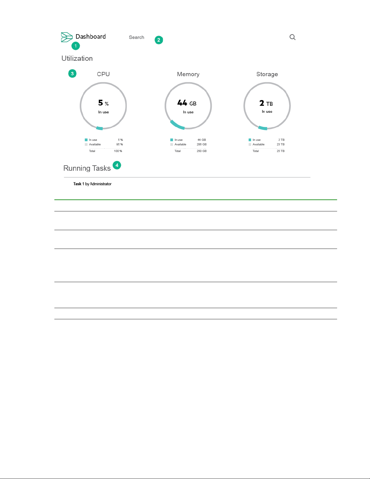
Item Description
1 Screen name and system icon—clicking the
system icon opens the navigation panel.
2 Search field—provides search capabilities for all
items in the system.
3 Utilization—provides a graphical overview of
system resource usage including CPU, memory,
and storage. Each circle graphic shows the total
resources in use.
4 Running Tasks—shows all user initiated tasks
running on the system including a progress bar and
estimated time remaining.
5* Critical alerts—shows all system critical alerts.
*not shown
10 HPE Hyper Converged 380 Management User Interface

Virtual machines (VM) overview
The HC 380 Management UI integrates virtual machine vending, management, firmware updates, and
operations analytics.
NOTE: The Hyper Converged 380 version 1.1 Update 2 adds support for VMs created in VMware
vCenter. For this release, the HC 380 Managment UI will recognize and can manage VMs created outside
of the UI. For more information, see the HPE Hyper Converged 380 Release Notes on the Hewlett
Packard Enterprise Information Library.
When creating VMs using the HC 380 Management UI, observe the following.
• IP addresses assigned to VMs are not validated. Ensure IP addresses provided are valid for the
network and not used elsewhere to avoid IP conflicts.
• All limitations of vCenter for VM vending operations apply to VM Vending done through HC 380. For
example, Duplicate VM names are not allowed.
• It is a VMware best practice to install VMWare Tools or Open VM Tools (OVT) on the VM. Ensure
either VMware tools or OVT is installed for all VMs.
Preparing the HC 380 for VM vending
Before deploying VMs, perform the following tasks:
• The HC 380 setup process does not utilize all available storage space in the system. To capture the
remaining system storage space, you must create additional datastores. For more information, see
"Creating datastores. "
• Upload an OVA template or an ISO file.
Before uploading an OVA or ISO file, review the information in "Images."
• Ensure one of the default VM size templates meet your requirements. The HC 380 Management UI
provides three virtual machine sizes by default: small, medium, and large. For more information, see
"Sizes."
Creating a VM
Prerequisites:
You must be logged in as Virtual Administrator or above.
About this task:
• Once the system has been populated with VMs created using the HC 380 Management UI, they will
be displayed in the Virtual Machines screen.
• VMs created outside of the HC 380 Management UI should be created in a user-managed shared
datastore (any shared datastore other than VSAManagement***). To manage VMs using the HC 380
Management UI, VMs should be created in the root folder of the HC 380 cluster.
• Typically production network vSwitches, used by the User/Production VMs, are created using vCenter.
Virtual machines (VM) overview 11

Procedure
1. In the left panel, click Virtual Machines.
2. Click the Add button in the middle of the screen or click the plus icon on the top right of the screen.
3. Under Name, enter a name for the virtual machine.
The name must be alphanumeric. It can contain hyphens (-), but no other special characters are
allowed. Names cannot be all numbers.
4. Under Size, select the size of the virtual machine.
The HC 380 Management UI is pre-populated with three VM sizes. To create a VM resource allocation
template, see "Sizes."
5. Under Initial Disk Image, click the magnifying lens icon and select from the available images.
6. Next to Networks, click the plus sign to add an available network.
12 Virtual machines (VM) overview

Click the magnifying glass for available networks.
By default DHCP is used.
To use a static IP address:
a. Click the plus icon to the right of Networks.
b. Uncheck Use DHCP.
c. Enter an IP address, subnet, and gateway.
7. Click Add.
.Click
The VM process starts and a status bar is displayed on the dashboard page.
Once VM creation is complete, the VM is displayed on the Virtual Machines page.
To see the VM details, click the VM name.
VM monitoring
VM events and health status can be viewed in the following locations:
• Virtual Machine (VMs)
• Activity screen
• Utilization screen
Once the system has been populated with VMs, created within the HC 380 Management UI, they will be
displayed in Virtual Machines screen.
The Virtual Machine screen provides information on all VMs deployed from within the HC 380
Management UI. VMs are displayed in chronological order based on the tasks performed on the VM.
Accessing the VM monitoring screen
Procedure
1. Click Virtual Machines in the navigation panel.
Virtual machines (VM) overview 13
The VMs are displayed.
2. Click a VM name.
The VM monitoring screen is displayed.
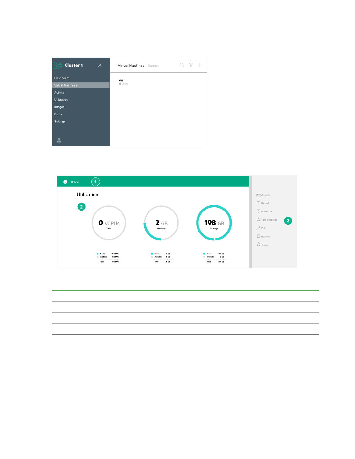
VM monitoring screen components
Virtual Machine management screen components are listed in the following table.
Item Description
1 Virtual machine status (includes: online, offline, alerts, and tasks)
2 Virtual machine resource utilization view
3 Virtual machine management panel
Beneath the resource overview, the Virtual Machine screen displays a line graph for storage usage and
network throughput. The line graphs provide minute-by-minute details on storage and network usage and
throughput.
14 Virtual machines (VM) overview

Item Description
1 Storage line graph showing usage
2 Network line graph showing usage
Beneath the line graphs, the Virtual Machine screen shows all activity on the VM and all snapshots that
have been saved using the VM management panel.
Item Description
1 Activity includes all alerts generated by the VM and all user tasks performed on the VM.
To view information about an Activity entry, click the entry.
2 Snapshots include all snapshots taken of the VM. Here you can revert to a saved
snapshot or remove a snapshot.
VM health status
The Virtual Machine screen displays health status and online/offline status for each virtual machine.
The following table lists VM health state colors and associated meaning.
Virtual machines (VM) overview 15

Color Health
Green Ok
Yellow Warning
Red Critical
Gray Disabled
White Unknown
VM management
The HC 380 Management UI offers the following VM management functions.
• Powering on and off a VM
• Editing and removing VMs
• Creating VM snapshots
• VM resource monitoring
• Assigning VMs to specific users
VM controls
Access to this feature is only available to Virtual Administrator and above. For more information, see
"User roles."
The VM console includes the following functions.
Feature Description
Console Opens a VM console session using the vCenter
Restart Restarts the VM
Power On/Off Power the VM on or off
Take Snapshot Captures a virtual machine state
Edit Allows editing features of a VM including name,
Remove Removes a virtual machine.
Assign VM Assign a VM to a user.
Accessing the VM console
Procedure
web client.
size, and network configuration.
1. Click Virtual Machines in the navigation panel.
2. Click Console in the VM management panel.
The VM console is displayed in a new tab.
3. Log in with your vSphere credentials.
16 Virtual machines (VM) overview

Restarting a VM
Prerequisites
VMware Tools or Open VM Tools is installed on the VM OS.
Procedure
1. Select Virtual Machine from the navigation panel.
2. Select a VM.
3. Click Restart in the VM console.
The VM restarts.
A progress bar is visible on the VM page.
Powering on a VM
Procedure
1. Select Virtual Machine from the navigation panel.
2. Select a VM in a power off state.
3. Click Power On in the right VM management panel.
The power on process is started.
A progress bar appears on the VM page.
Powering off a VM
Procedure
1. Select Virtual Machine from the navigation panel.
2. Select a VM in a power on state.
3. Click Power Off in the right VM management panel.
The power off process is started.
A progress bar appears on the VM page.
VM snapshots
The snapshot feature is used to capture a VM state. Snapshots can be taken when the VM is powered on
or off. The snapshot is stored on the VM management page and can be reverted to at any time.
VM snapshots hold the following information:
• The VM power state at the time the snapshot was taken.
• The data and files that make up the virtual machine, including disks, memory, and other devices, such
as virtual network interface cards.
Virtual machines (VM) overview 17

Creating a VM snapshot
VM snapshot names must be unique. The same snapshot name cannot be used more than once, even
for separate VMs.
Procedure
1. Click Take Snapshot in the right panel.
2. Enter a name for the snapshot.
3. Click the Take Snapshot button.
The snapshot is captured on the Activity page and under Snapshots on the individual VM page.
Removing a snapshot
Procedure
1. Click Virtual Machines in the left panel.
2. Select the VM containing the snapshot you want to delete.
3. Under Snapshots click "..." to the right of the snapshot.
4. Click Remove.
Reverting to a saved snapshot
Procedure
1. Click Virtual Machines in the left panel.
2. Select the VM you want to revert to a saved snapshot.
3. In the VM monitoring panel, under Snapshots, click ... to the right of the snapshot you want to revert
to.
4. Click Revert.
A progress bar appears on the VM page.
Once complete, the VM will power on.
Editing a VM
Storage resources for a virtual machine can only be increased; they cannot be decreased. If it is
necessary to decrease storage allocations of a VM, you must delete and redeploy the VM.
Prerequisites
The VM is powered off.
Procedure
1. Click Virtual Machines in the left panel.
All VMs are displayed.
18 Virtual machines (VM) overview

You can search using either the search or filtering features.
2. Click the VM you want to edit.
3. Click Edit in the right panel.
You can change the name, change or add a network, or increase resource allocations.
4. After completing edits, click OK.
5. The VM will automatically power on.
Removing a VM
Prerequisites
Prerequisite: The VM is powered off.
Procedure
1. Click Virtual Machines in the left panel.
All VMs are displayed.
You can search using either the search or filtering features.
2. Click the VM you want to remove.
3. Click Remove in the right panel.
4. Click Yes, Remove.
Assigning a user to a VM
The Assign function allows you to assign a VM to a particular user. This feature can be used to assign
users to VMs created outside of the HC 380 Management UI.
VMs created within the HC 380 Management UI will automatically be assigned to the user that created
the VM.
Prerequisites
User names have been assigned by the Administrator.
Procedure
1. Click Virtual Machines in the left panel.
All VMs are displayed.
You can search using either the search or filtering features.
2. Click the VM you want to Assign a user to.
3. Click Assign in the right panel.
Virtual machines (VM) overview 19
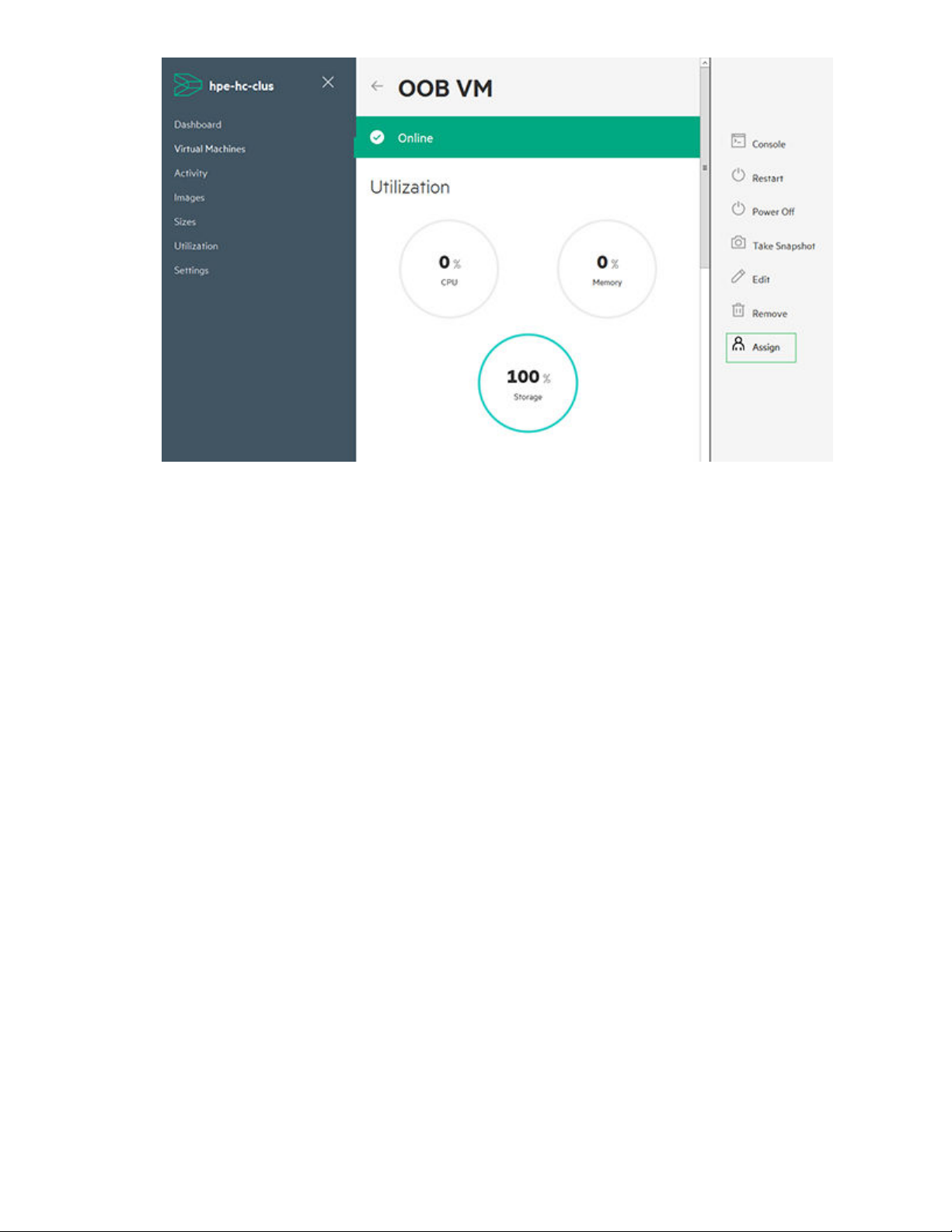
4. Enter username to whom you want to assign the VM.
20 Virtual machines (VM) overview

System monitoring tools
VMs resources, utilization, and alerts can be monitored using three functions.
•
Virtual machines—Provides individual VM monitoring.
• Activity screen—Displays all alerts and system events by state and status.
• Utilization screen—Graphical interface of all VM by resource utilization.
System alerts
System alert colors
System events are categorized by their severity.
Alert severities include the following.
Color Health
No color Ok
Yellow Warning
Red Critical
System alert types
System notifications appear on the main dashboard page and individual VM monitoring pages. They can
also be viewed on the Activity screen.
Notification type Description
Alerts Actionable system events including critical errors,
Event alerts Non-critical system events
Tasks Status of tasks performed by the user including
System alert dialog box
Clicking a system alert brings up the system alert dialog box. Actionable alerts include a toggle switch
that can be moved from Active to Cleared. This toggle switch can be used to indicate an alert has been
managed. Hewlett Packard Enterprise recommends addressing the issue before clearing the alert. If
support is required, see "Support and other resources."
warnings, and notifications
start/stop, time remaining, and completed date/time
System monitoring tools 21
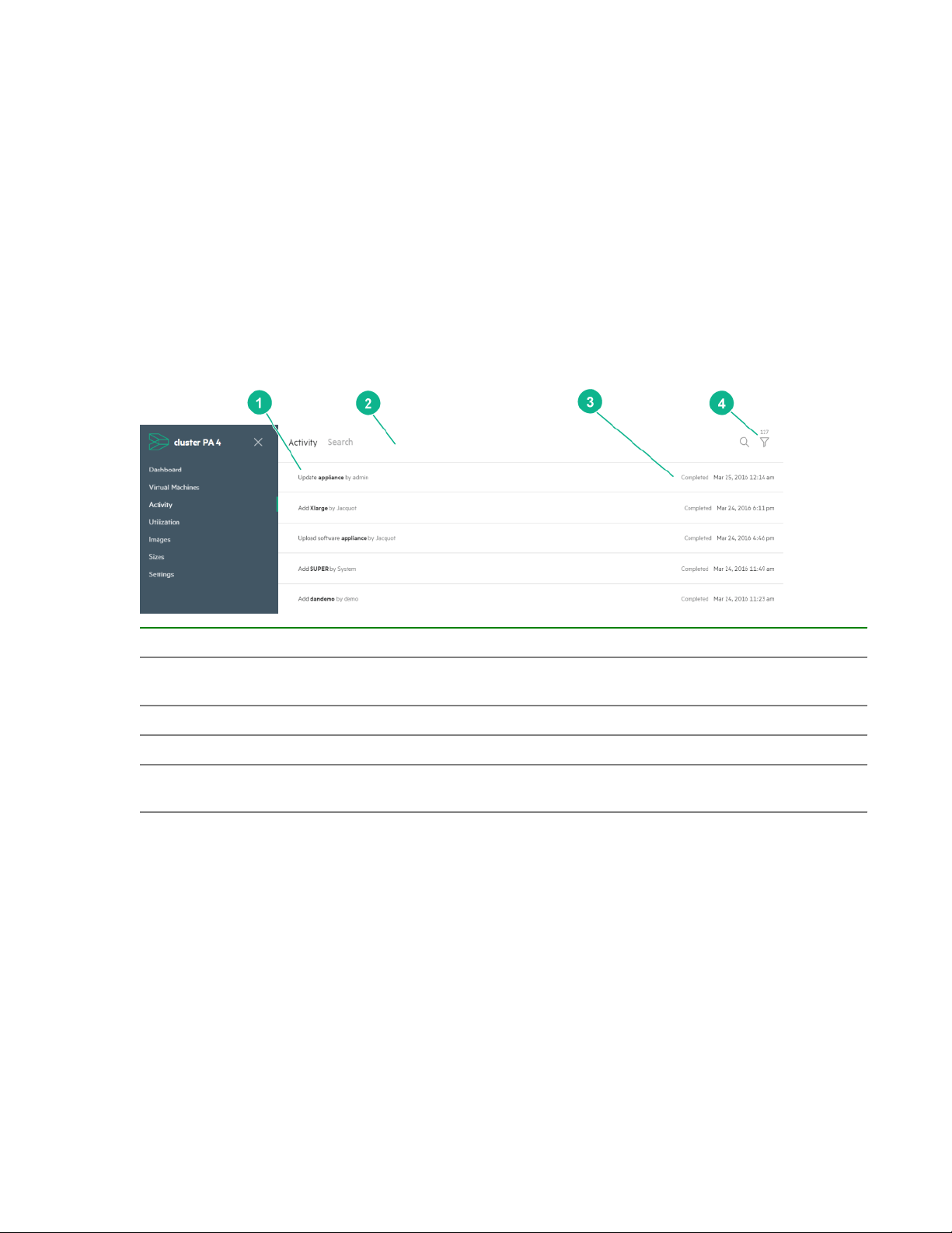
Activity screen
The Activity screen provides a list of all system and VM alerts and tasks. From the Activity screen, you
can locate system and VM events using the search and filtering tools.
Accessing the Activity screen
Procedure
1. Open the Navigation panel.
2. Click Activity in the Navigation panel window.
The Activity screen is displayed.
Activity screen components
Component Description
1 Displays the alert or task and whether it was user
2 Search bar for searching for an alert.
3 Displays the status and date of the event .
4 Displays the total number of events and allows
Utilization screen
The Utilization screen provides a graphical view of each VMs resource utilization.
or system generated.
filtering by state and status .
22 System monitoring tools

The total area of each container represents the resource usage for that VM as compared to other VMs in
the cluster.
By clicking the Area drop-down box, the container size can be toggled between:
• Memory usage
• Storage usage
The utilization legend, located beneath the utilization graphic, provides information on the color and
related utilization percentage.
By clicking the Color drop-down box, the container color can be toggled between:
• Memory usage as a percentage of the total allocated amount
• CPU usage as a percentage of the total allocated amount
• Disk usage as a percentage of the total allocated amount
Clicking a utilization container will open the VM view for that VM.
System monitoring tools 23

Images
IMPORTANT: If using an ISO file to create a VM, the operating system must be installed and
configured using the VM console. After installing and configuring the operating system, you must
install VMware Tools or OVT for full HPE HC 380 Management UI functionality. Failure to do so will
result in limited functionality within the HC 380 Management UI. Hewlett Packard Enterprise
recommends that you use OVA templates to create VMs in the HC 380 Management UI.
Using the Images screen, you can upload and manage images used to deploy VMs in your environment.
The HC 380 Management UI supports both ISO files and OVA virtual image template files.
OVA templates
Hewlett Packard Enterprise recommends using OVA templates to deploy VMs using the HC 380
Management User Interface.
Observe the following when using OVA templates:
• Do not use the VSAManagement datastore to upload OVA templates. It must only contain the
management VMs.
• Creating OVA templates is not currently supported using the HC 380 Management UI. Use the
VMware vSphere desktop or web client to create OVA files.
• If a suitable VM, that has the preferred OS and software, is already running in any VMware vSphere
environment, the vSphere desktop or web client may be used to export that VM as an OVA file. The
OVA file can be uploaded to the HC 380 Management UI.
• Before creating an OVA template file unmount any attached ISO files. If the OVA includes a mounted
ISO file, it will not be recognized by the HC 380 Management UI.
• Once the OVA is uploaded, it is available in the list of images.
The image is then available to all VM users and it can be used to deploy additional VMs.
• When a VM is created using an OVA, the VM comes up with the OS/applications that was present in
the OVA. IP addresses can be configured (DHCP or static) during VM creation when connecting the
VM to one or more networks and the VM could be accessed over the network directly without having
to use the VM console.
• The HC 380 Management UI will pull in templates uploaded to shared datastores. Templates can be
uploaded to any datastore other than the VSAManagement datastore.
ISO file guidelines
ISO files can be uploaded to the HC 380 Management User Interface and used to deploy VMs.
Observe the following when using an ISO file to deploy VMs:
• When a VM is deployed using an ISO, the VM created is an empty VM with a blank disk. The ISO is
attached as a virtual DVD to the VM when the VM is powered on.
• A VM deployed using an operating system ISO file is not usable until the operating system has been
24 Images
installed and configured using the VM console.

◦ After the operating system installation is complete, the ISO is detached and additional software
may be installed and additional configuration performed.
◦ The IP address assigned to the VM will not be recognized until after the operating system has been
installed.
• After the operating system has been installed and configured, the VM can be used to create an OVA
template. Use VMware vCenter to create the OVA template. The OVA file can be uploaded to the HC
380 Management UI and used to deploy additional VMs.
• Use ISO images where OS gets bundled in one file.
Open VM Tools (OVT) and VMware tools
HC 380 Management UI does not support installation of either OVT or VMware tools in a VM. This must
be done using VMware vCenter. Once a reference VM is built with the OS installed, the applications
configured, and either OVT or VMware tools installed, the VM can be used to create a template OVA file
in the VMware vSphere client. This template OVA file can be uploaded using the HC 380 Management UI
and used to deploy VMs.
For more information see, "OVA template guidelines."
Browser recommendations
• Hewlett Packard Enterprise recommends using a browser outside of the HC 380 Management VM to
create VMs.
• While Firefox is the recommended browser to use in the HC 380 Management VM, Chrome is the
recommended browser for accessing and managing the HC 380 Management UI.
Chrome has the highest upload limits and provides the best performance.
• Browsers may fail to upload files when uploading files from an NFS/Windows Share or drives shared
via remote desktop.
• Upload of OVA and ISO images have the following limits.
◦ IE 11: 2GB
◦ Mozilla: 8 GB
◦ Chrome: 9 GB
Adding an Image
Prerequisites
Access to this feature is only available to Virtual Administrator and above. For more information, see
"User roles
Procedure
1. Click Images in the left panel.
2. Click the plus icon at the top right of the screen.
Images 25

3. Add a name for the image.
If no name is added, the file name will be used.
4. Click Choose File and select an ISO or OVA file to upload.
If uploading an ISO file, click the magnifying glass icon and choose the OS type.
5. Click Add.
Replacing an image
From the edit screen, ISO and OVA files can be replaced with a new file.
Procedure
1. Click Images on the left panel.
2. Click the pencil icon to the right of the image you want to edit.
3. To replace the image, click Choose File and navigate to the replacement ISO or OVA file.
4. Click OK.
Removing an image
Prerequisites
The ISO is not mounted by a VM.
Procedure
1. Click Images on the left panel.
2. Click the pencil icon to the right of the image to be removed.
26 Images

3. Click Remove.
4. Click OK to complete the action.
Images 27

VM sizes templates
NOTE: Access to this feature is only available to Virtual Administrator and above. For more information,
see "User roles."
The Sizes screen allows you to add, edit, or delete VM resource allocation sizes.
Virtual machine size default templates
The following pre-configured virtual machine sizes are available.
Size Specifications
Small
Medium
Large
1 vCPU
2GB memory
20GB storage
2 vCPU
4GB memory
40GB storage
4 vCPU
8GB memory
60GB storage
Size calculations for OVA templates
Multi-disk VMs are not currently supported in the HC 380 Management UI. Uploading a multi-disk OVA file
will result in a single disk being created in the HC 380 Management UI.
When creating an OVA-based VM, using the HC 380 Management UI, the final drive size is determined
by:
• The number and size of disks called for by the OVA file
• The disk size selected in the HC 380 Management UI, or the OVA drive size, whichever is greater.
• Whichever drive size is greater, the drive required by the OVA file or the HC 380 size template
◦ Single disk OVA file example: The HC 380 size template is larger than the OVA drive size.
The OVA template requires one 1GB virtual drive.
The Medium (40GB) size template is selected in the HC 380 Management UI.
(The HC 380 Management UI ignores the OVA template drive size and uses the Medium template
selected)
Total assigned disk space 1 drive x 40G for a total of one 40GB drive.
28 VM sizes templates

NOTE: The additional 39GB will appear in the VM as unallocated space.
• Multi-disk OVA file example: The OVA individual drive size is greater than the selected HC 380
size template.
If the individual drive size called for by the OVA file is greater than the selected size template, the
system uses the size called for by the OVA file for each drive.
◦ Example
The OVA file requires five 40GB drives.
The Small (20GB) size template is selected in the HC 380 Management UI.
(The HC 380 Management UI ignores the Small template and uses the 40GB size requested by the
OVA file.)
The disk size is assigned to each drive requested by the OVA template file:
(Total assigned disk space = 5 drives x 40GB each for a total of one 200GB drive)
Adding virtual machine size templates
Virtual machine size limitations may vary depending on your configuration and available resources.
However, the HPE HC 380 Management UI only allows allocations up to:
• 128 vCPUs
• 1024GB of memory
• 62TB of storage
To add virtual machine sizes to the system:
Procedure
1. Click Sizes in the left panel.
2. Click the plus icon on the top right of the screen.
The Add Size pop-up is displayed.
VM sizes templates 29

3. Enter the VM size information.
a. In Name, enter a name for the new size.
b. In vCPUs box, enter the number of vCPUs.
c. In the Memory (GB) box, enter the amount of memory in GB.
d. In the Disk Space (GB) box, enter the disk storage amount in GB.
4. Click Add button.
The new size will be available for deploying VMs.
Editing virtual machine size templates
Changing a VM size template will not affect VMs that were previously deployed with that template.
Procedure
1. Click Sizes in the left panel.
2. Click the pencil icon in the Size box you want to edit.
The Edit Size panel appears.
30 VM sizes templates

3. Make adjustments per your requirements.
4. Click OK.
Removing a Size template
Removing a VM size template will not affect VMs that were previously deployed with that template.
Procedure
1. Click Sizes in the left panel.
2. Click the pencil icon in the Size box you want to edit.
3. Click Remove.
VM sizes templates 31

Settings panel overview
NOTE: Accessing Settings requires being logged in as Infrastructure Administrator. For more information,
see user roles.
The setting screen displays the cluster identity information as well as connection information for the
following features.
Feature Description
Identity Information displayed includes: the cluster name,
vCenter Displays the vCenter IP address
Directory Allows connection to an LDAP or ActiveDirectory.
Nodes Displays node information, including the node
Procedures for setting up the identity, connecting to vCenter, and setting up nodes are outlined in the
HPE Hyper Converged 380 Installation Guide.
IP address information, DNS information,
embedded HPE OneView IPv4 address, and the
data center name
For more information, see "Configuring LDAP or
Active Directory."
name and iLO IP address
Functions in the settings panel include the following.
32 Settings panel overview

Feature Description
Update software Update the HC 380 Management UI, HPE
OneView application, and SPP firmware from .bin
files. To update the software see, "Upgrading the
system."
Backup Creates a backup file for both the HC 380
Management UI and HPE OneView application
Restore from backup Restores HPE OneView and the HC 380
Management UI from a backup file
Create support dump Collect support logs and information for HC 380
troubleshooting.
Restart Restarts the HC 380 Management UI
Backing up the HC 380 Management UI VM
The Backup feature creates a backup of the HPE HC 380 Management UI VM and the associated
OneView application. It does not back up user-created VMs.
NOTE: Hewlett Packard Enterprise recommends backing up your appliance configuration on a regular
basis, preferably daily and especially:
• After adding hardware
• After changing the appliance configuration
• Before and after updating the system updates
NOTE: System backups are performed on demand by the user. The system does not automatically
perform backups as a background task.
Use a backup file to do the following:
• Restore the appliance from which the backup file was created.
• Restore the settings to a different appliance. For example, if an appliance fails and cannot be repaired,
you can use a backup file to restore the management configuration settings and management data to
a replacement appliance created from the same version of the virtual machine image.
The appliance stores one backup file on the appliance at a time. Creating a backup file replaces the
current backup file.
Creating an HC 380 Management UI Backup file
Prerequisite: You must be logged in as Infrastructure Administrator.
NOTE: If you start a backup while a support dump is in progress, the backup operation does not proceed
until the support dump operation completes. If you start a support dump while a backup operation is in
progress, you have the option of canceling the backup and proceeding with the support dump.
To create a system backup file:
Settings panel overview 33

Procedure
1. Click Settings in the left panel.
If the left panel is unavailable, click the HC 380 icon on the top left.
2. Click Backup in the right panel.
A backup file is generated.
3. Click Download backup to download a copy of the backup file.
Download the backup file and save it to an off-appliance location before running the next backup
process. The system only stores one backup file. Creating another backup will overwrite the backup
stored the system.
Restoring the HC 380 Management UI from a backup file overview
When restoring a backup, VMs created after the backup are still visible from HPE HC 380 Management
UI as out-of-box VMs and can be managed from the management UI.
Restoring an appliance from a backup file replaces all management data and most configuration settings
with the data and settings in the backup file, including:
• Registered vCenter credentials
• LDAP/ActiveDirectory configuration
• Registered iLOs
• Management information about VMs created through HC 380 Management UI
Restoring the HC 380 Management UI from a backup file
The appliance is not operational during the restore operation, which can take several minutes to perform.
A restore operation cannot be canceled or undone after it has started. The appliance blocks login
requests while a restore operation is in progress.
Prerequisites
You are logged in as Infrastructure Administrator.
Procedure
1. On the left panel, click Settings.
2. Click Restore From Backup in the right panel.
3. Click Choose File and select a backup file.
4. Click Upload and Restore.
Creating a support dump file
The Create Support Dump feature generates a compressed SDMP file appropriate for diagnosis and
troubleshooting by Hewlett Packard Enterprise support.
Prerequisites
You are logged in as Infrastructure Administrator.
34 Settings panel overview

Procedure
1. On the left panel, click Settings.
2. Click Create support dump in the right panel.
The support dump file is encrypted by default.
To create an unencrypted support dump file clear the check box next to Encrypt support dump?
3. Click OK.
The support file is created and can be downloaded to a local system folder.
Restarting the HC 380 Management UI
The Restart function will only restart the HC 380 Management UI. It does not restart the entire HC 380
system.
To restart the HC 380 Management UI:
Procedure
1. Click Settings in the left panel.
2. Click Restart in the right panel.
Settings panel overview 35

Initial setup
Creating datastores
The initial configuration setup and process only utilize a portion of the total available storage. To utilize the
remaining storage in your HC 380, you must create datastores.
Procedure
1. Open a browser and navigate to the vSphere Web Client.
The login window appears.
2. Enter your user name and password for the vSphere Web Client.
3. Click Login.
4. To familiarize yourself with the layout of the vSphere Web Client, review the information on the
Getting Started tab.
5. In the Navigator, select vCenter.
6. In the Navigator, select Hosts and Clusters > Cluster.
7. Select the specific cluster for which you want to create a datastore.
The Summary tab for the selected cluster appears.
36 Initial setup

NOTE: Depending upon the ESXi version installed in your environment, the information in the
window varies.
8. Select the Manage tab, and then select HP Management.
The Actions menu appears on the right side of the window.
The vSphere Web Client may not always refresh quickly. If you are not seeing what is expected, click
the Refresh icon in the top menu bar or the disk refresh icon on the right side of the window.
9. From the Actions menu, select Create Datastore.
The Create Datastore wizard appears. Alternatively, right-click the cluster name and select All HP
Management Actions > Create Datastores .
10. Select the default location, and then click Next.
Initial setup 37

11. On the Select storage screen, select the applicable storage pool.
a. Select the size and number of datastores you want to create.
b. Select NETWORK_RAID_10 in the RAID level drop-down box.
12. Click Next.
The storage window appears.
13. Enter a unique name for the new datastore, and then click Next.
14. On the Validation screen, verify that the information entered is correct.
If so, click Next.
If not, click Back and return to the applicable screen to edit it.
15. On the Ready to complete window, click Finish to create the datastore.
Configuring LDAP or Active Directory
The HC 380 Management UI, when used in conjunction with LDAP or AD, can restrict users so that they
only see their own VMs. If HC 380 is not configured with LDAP or AD, this functionality is not available.
If the HC 380 is configured with LDAP or AD, use the following steps to connect to an LDAP or AD server:
Procedure
1. Click Connect in the Directory section.
2. Select LDAP for a Linux server or Active Directory for a Windows server.
3. Provide the fully qualified domain name or IP address for the LDAP or Active Directory server host and
click Connect.
The HC 380 appliance downloads the essential certificate.
4. Read through the certificate, and click Trust.
5. For the LDAP server, provide login credentials along with the Base Domain Name and click Verify.
Base Domain Name example: DC=hpe DC=com
6. Provide a user name and password with access to the directory and click OK.
38 Initial setup

The list of directory groups appears.
7. Click the plus sign next to each directory group to associate groups in the directory with the HC 380
user roles.
NOTE:
• Verify connectivity between the HC 380 and your AD server. For AD Certificate Services, HC 380
uses the default port (636) to connect to the AD server using SSL.
• If the directory server is added as a user in the registered groups, do not prefix the domain name
before the username (domainname\username).
User roles system access
Before using the system, Hewlett Packard Enterprise recommends that the following user groups are
added to the Active Directory/LDAP and users added to each group. For information about adding the
user groups to your server, see the documentation for your server.
The following table defines the list of user groups and the access rights of each group.
User Access
Infrastructure Administrator • Systemwide configuration: view and edit, Dashboard
• VM Actions: view activity
• VM-Sizes: add and edit
• VM- Images: add and edit
Virtual Administrator • VM Actions: view activity
• VM-Sizes: add and edit
• VM-Images: add and edit
Virtual User • VM: actions
• View: activity
Read-only User • Systemwide configuration-View
• Dashboard
• View: activity
• VM-Sizes: view
• VM-Images: view
• VM: view
Initial setup 39

Password recommendations
Microsoft and VMware passwords
Before adding putting the system into production, Hewlett Packard Enterprise recommends changing the
following system passwords:
• Microsoft Windows password
To change the Microsoft Windows password, access Windows on the Management VM.
Use the normal Windows method to change the administrator password.
• VMware vCenter password
To change the VMware vCenter password for the administrator@vsphere.local user, access the SSO
vdcadmin tool from the Management VM.
• vSphere passwords
To change the vSphere passwords, access the ESXi shell with the default root password (HyperConv!
234).
40 Initial setup

HC 380 hardware information
For information on troubleshooting hardware issues, see the maintenance and service guide for the
hardware component on the
Before replacing any devices in the system, see the HPE Hyper Converged 380 Installation Guide for
specific information on system and node configuration and requirements.
Nodes in the HC 380 must be homogeneous and disk clusters must be configured using the same type
and size of disk.
Observe the following component replacement rules:
• Processors in a node must all be the same type and must be in the supported processor list in the
product QuickSpecs.
• Memory replaced in a node must be replaced with memory of the same size and type and must be in
the supported memory list in the product QuickSpecs.
• Drives replaced in a node must be replaced with drives of the same size and type and must be in the
supported drives list in the product QuickSpecs.
• For more information, see the HC 380 quickspecs on the Hewlett Packard Enterprise website.
For support options, see "Support and Other Resources".
Hewlett Packard Enterprise website.
HC 380 hardware information 41

Upgrading the system
System upgrade instructions
For system upgrade instructions, see the
HPE Hyper Converged 380 Upgrade Guide.
42 Upgrading the system

Troubleshooting
Troubleshooting a USB recovery/reset
Check the contents of log files in host directory /scratch/log/kickstart to determine the problem.
Begin with these files. Use the cat command to display them:
• validation.txt
• system.info
• post_kickstart.log
Remove from Management Group option is not available
Symptom
The Remove from Management Group option is not available as described in step 6 of "Finalizing the
VMware ESXi and StoreVirtual VSA configuration" in the HPE Hyper Converged 380 User Guide
Action
Complete the following steps:
1. After removing the failed StoreVirtual VSA from the cluster, wait for restriping to complete.
2. On the Management VM, and then open the StoreVirtual CLI.
a. Go to the Windows start screen and enter the following command:
CLIQ
The HPE StoreVirtual CLI Shell Icon will appear.
b. Click the HPE StoreVirtual CLI Shell Icon.
3. From the StoreVirtual CLI, execute the following command:
modifyGroup login=<Any_Manager_VSA_IP> username=<MG_Admin_Username>
password=<MG_Admin_Password> node=<The delimited list of IP addresses of
the storage systems the cluster comprises>
NOTE: Do not specify the IP address of the failed StoreVirtual VSA in any parameter of the
modifyGroup command.
Example of completing the modifyGroup command:
modifygroup login=1.1.1.1 username=administrator password=adminpassword
node=1.1.1.1;1.1.1.2;1.1.1.3
4. The following prompt is displayed when you attempt to execute the command:
The operation is irreversible. Are You Sure <y/n>?
Press Y to continue.
5. Wait for the process to complete. It will take several minutes.
Troubleshooting 43

HPE HC 380 troubleshooting topics
For troubleshooting topics, see the HPE Hyper Converged 380 Release Notes.
44 Troubleshooting

Support and other resources
Accessing Hewlett Packard Enterprise Support
• For live assistance, go to the
• To access documentation and support services, go to the Hewlett Packard Enterprise Support
Center website.
Information to collect
• Technical support registration number (if applicable)
• Product name, model or version, and serial number
• Operating system name and version
• Firmware version
• Error messages
• Product-specific reports and logs
• Add-on products or components
• Third-party products or components
Accessing updates
• Some software products provide a mechanism for accessing software updates through the product
interface. Review your product documentation to identify the recommended software update method.
Contact Hewlett Packard Enterprise Worldwide website.
• To download product updates, go to either of the following:
◦ Hewlett Packard Enterprise Support Center Get connected with updates page
◦ Software Depot website
• To view and update your entitlements, and to link your contracts and warranties with your profile, go to
the Hewlett Packard Enterprise Support Center More Information on Access to Support
Materials page.
Websites
• Hewlett Packard Enterprise Information Library
• Hewlett Packard Enterprise Support Center
• Contact Hewlett Packard Enterprise Worldwide
• Subscription Service/Support Alerts
IMPORTANT: Access to some updates might require product entitlement when accessed
through the Hewlett Packard Enterprise Support Center. You must have an HPE Passport set up
with relevant entitlements.
Support and other resources 45

• Software Depot
• Customer Self Repair
• Insight Remote Support
• Serviceguard Solutions for HP-UX
• Single Point of Connectivity Knowledge (SPOCK) Storage compatibility matrix
• Storage white papers and analyst reports
Remote support
Remote support is available with supported devices as part of your warranty or contractual support
agreement. It provides intelligent event diagnosis, and automatic, secure submission of hardware event
notifications to Hewlett Packard Enterprise, which will initiate a fast and accurate resolution based on your
product’s service level. Hewlett Packard Enterprise strongly recommends that you register your device for
remote support.
For more information and device support details, go to the Insight Remote Support website.
Warranty information
To view the warranty information for your product, see the links provided below:
HPE ProLiant and IA-32 Servers and Options
www.hpe.com/support/ProLiantServers-Warranties
HPE Enterprise and Cloudline Servers
www.hpe.com/support/EnterpriseServers-Warranties
HPE Storage Products
www.hpe.com/support/Storage-Warranties
HPE Networking Products
www.hpe.com/support/Networking-Warranties
Regulatory information
To view the regulatory information for your product, view the Safety and Compliance Information for
Server, Storage, Power, Networking, and Rack Products, available at the Hewlett Packard Enterprise
Support Center:
www.hpe.com/support/Safety-Compliance-EnterpriseProducts
Additional regulatory information
Hewlett Packard Enterprise is committed to providing our customers with information about the chemical
substances in our products as needed to comply with legal requirements such as REACH (Regulation EC
No 1907/2006 of the European Parliament and the Council). A chemical information report for this product
can be found at:
www.hpe.com/info/reach
For Hewlett Packard Enterprise product environmental and safety information and compliance data,
including RoHS and REACH, see:
www.hpe.com/info/ecodata
For Hewlett Packard Enterprise environmental information, including company programs, product
recycling, and energy efficiency, see:
www.hpe.com/info/environment
46 Support and other resources

Documentation feedback
Hewlett Packard Enterprise is committed to providing documentation that meets your needs. To help us
improve the documentation, send any errors, suggestions, or comments to Documentation Feedback
(docsfeedback@hpe.com). When submitting your feedback, include the document title, part number,
edition, and publication date located on the front cover of the document. For online help content, include
the product name, product version, help edition, and publication date located on the legal notices page.
Support and other resources 47

Powering the HC380 system on and off
Manually powering on the HC 380
Procedure
1. Power on host 1 only, either by physically pressing the power button, or by using the iLO console.
Allow the server to complete its boot-up into VMware vSphere ESXi.Start the HC 380 Management
VM.
2. Start the HC 380 Management VM.
3. Access the HC 380 Management VM using remote desktop software.
If the connection is not responding, the HC 380 Management VM might be booting.
This process can take a few minutes.
4. Check that all the Windows services have started.
5. Power on the remaining ESXi hosts.
Wait 10 minutes.
6. Confirm all ESXi hosts have successfully booted.
7. In the HC 380 Management VM, ensure all StoreVirtual VSAs have successfully started.
8. Launch vCenter and ensure that all expected datastores are available and that all virtual machines
are in a power off state.
If datastores are not available, or virtual machines are in an unavailable state:
• The VSA storage is in the process of being ready, or
• ESXi hosts have not yet configured all connection
If this occurs, wait a few minutes for all resources to be available and healthy before proceeding.
9. Manually start HPE-HC-Oneview and HPE-HC-mgmtui VMs.
10. Manually start any user-created VMs.
11. Enable vSphere HA on the computer cluster.
In VMware vCenter:
a. Right-click the hpe-hc-clus cluster (or the cluster name you provided in InstantOn setup) in
VMware vCenter.
b. Select Settings.
c. Under Services, turn on the vSphere HA by clicking the Edit button.
12. Migrate the HC 380 Management VM from local storage on Host1 to the Management datastore
(which is a shared/clusterwide datastore).
48
Perform a storage vMotion from local storage to the SAN datastore on Host 1.

Manually powering off the HC 380
These instructions assume that you are using the VMware vSphere Web Client.
Procedure
1. Manually shut down all user-created VMs, including the HPE-HC-OneView and HPE-HC-mgmtui
VMs.
HPE-HC-OneView takes a few minutes to shut down.
2. Migrate the HC 380 Management VM to local storage on Host 1.
a. If the HC 380 Management VM is controlled by a host other than Host 1, perform a vMotion to Host
1.
b. Perform a storage vMotion from the SAN datastore to local storage on Host 1.
3. Disable VMware HA.
This ensures that VMware HA does not override virtual machine startup and shutdown settings.
a. Right-click the hpe-hc-clus cluster (or the cluster name you provided in HPE OneView InstantOn
setup) in VMware vCenter.
b. Select Settings.
c. Under Services, turn off the vSphere HA by clicking the Edit button.
4. Enable the virtual machine startup/shutdown option on all ESXi hosts on the cluster.
a. Right-click the host and go to settings.
b. Under VM Startup/Shutdown, turn on Automatically start and stop the virtual machines with
the system by clicking the Edit button under Virtual Machine Startup and Shutdown.
49

c. Ensure VSA virtual machines and HC 380 Management VM (HPE-HC-mgmt-XXXXXXXXXX) are in
the Automatic Startup Section. There will be one VSA VM per host. The HC380 Management VM
will only be on host 1.
The HC 380 Management VM is configured with a startup delay of 180 seconds.
d. Ensure that all user-created virtual machines are listed in the Manual Startup section.
e. To accept the settings, click OK.
5. Shut down the storage cluster.
You can either shut down the storage cluster using StoreVirtualCMC or shut down the VSA node with
the vCenter vSphere desktop client or the vCenter vSphere Web client. Hewlett Packard Enterprise
recommends using StoreVirtual CMC to shut down the storage clusters.
a. To shut down the storage cluster with StoreVirtual CMC:
I. Access and launch the StoreVirtual CMC from the start menu of the HC 380 Management
VM.
II. Log in to the CMC.
50
III. Right-click the management group name and select Shutdown Management group.

The CMC will no longer display information about the management group.
IV. Access vCenter on the HC 380 Management VM and confirm that all VSA virtual machines
have shut down. If not, wait until all VSA virtual machines are in a powered off state. This
process will take a few minutes.
b. To shut down the VSA node using VMware vCenter desktop client:
I. Click the Cluster object in vCenter.
II. Click the virtual machine tab to list all virtual machines.
III. Click the Name column.
IV. Select all VSA virtual machines.
V. Right-click and select Power.
VI. Select Shutdown Guest.
c. To shut down the VSA node using the VMware vSphere Web client:
I. On the home screen, select vCenter, and then select Clusters.
II. Select the system cluster, and then select the Related Objects tab.
III. Select the Virtual Machine sub tab.
IV. Select all the VSA virtual machines.
V. Right-click and select shutdown guest OS.
VI. All of the StoreVirtual VSAs are gracefully shut down.
6. Access VMware vCenter and shut down all ESXi nodes except Node 1.
7. After you confirm that all hosts have been successfully shut down:
a. Shut down Host 1.
b. Log out of the HC 380 Management VM before the automatic shutdown completes.
You can use iLO to verify that all systems are powered off.
51

System recovery options
NOTE: The system recovery procedures outlined in this chapter do not sanitize the drives.
The following system reset options are available:
• Quickreset
Use the quickreset options to reset the HC 380 system back to factory default settings. Upon
completion, the system will be in the same state as it was shipped from the factory. All user files on the
system are lost, including user created VMs.
• USB-based node recovery
Use the USB-based node recovery procedure to recover a single node. This procedure requires that
the node is manually configured prior to reintegration into the HC 380.
• System reset
Use the system reset procedure to recovery an entire system. This procedure removes all software,
settings, and user created VMs from the nodes and requires adding the factory installed software and
files. All user files on the system are lost, including user created VMs.
Quickreset
Quickreset is a set of scripts that can be used to reset an HC 380 to its default state as shipped from the
factory.
Quickreset can be used when the whole environment must be reset, for example, after a proof-of-concept
or demonstration configuration.
It can also be used when OneView InstantOn must be rerun. For example, to reconfigure with different IP
addresses, or to overcome an issue that occurred during deployment. It can only be used when the whole
environment must be reset, not just a single server.
Quickreset restores each server to its initial state, but does not reinstall ESXi. If ESXi on the host
becomes unstable, then a full reinstall using the USB Recovery method outlined in USB-based node
recovery or system reset.
Performing a Quickreset
For Quickreset instructions, see the HPE Hyper Converged 380 Installation Guide.
USB-based node recovery or system reset
Use the following procedures to recover a single node or reset the entire system (up to 16 nodes) to
factory defaults.
CAUTION: Back up your data before performing a USB-based node recovery. All data and
configuration information will be lost when resetting an entire system to factory defaults.
NOTE: Resetting to factory defaults does not physically erase data stored on hard drives or SSDs. The
system will no longer recognize the data; however, it will remain on the drive.
Prerequisites for USB-based node recovery or system reset
Ensure you have the following.
52

• One USB drive with a minimum of 2 GB free capacity.
When resetting the entire system, you can use up to 16 USB drives, one per node, to reset the nodes
in parallel and expedite the overall process.
• One KVM cable, if not using iLO.
• When resetting the entire system, you can use up to 16 KVM cables, one per node, to reset the nodes
in parallel and expedite the overall process.
• A monitor and keyboard are optional if access to the nodes is available through iLO.
• A Windows laptop or workstation for creating a bootable USB drive.
• A utility, such as UNetbootin, for creating a bootable USB drive.
• (For full system reset only) A Windows laptop to access Node 1 and perform initial system
configuration.
• (For full system reset only) Download and install the PuTTY utility and PSCP.
• VMware vSphere must be installed in order to access the node and configure the HC 380
Management VM.
Prerequisites
IMPORTANT: Prior to running USB node recovery or system reset, all PCI adapters added to
affected nodes after deployment MUST be removed or disabled in the system BIOS. This does not
apply to network interface cards.
Files required for USB Recovery
To download the HPE HC 380 Recovery Suite 1.1 Update 2 software, see the Hewlett Packard
Enterprise website.
You will be required to log in to your HPE Passport account (you can create an account if one does not
exist).
Select the HPE Hyper Converged 380 link and navigate to the Recovery Suite page (and support).
The following table lists the files that must be downloaded and the actions to be taken with them.
Description of download file Action with download file
HPE HC380 1.1U2 USB Recovery Tools 6.0 U2
(iso file)
HPE HC380 1.1U2 Management VM 6.0U2 (zip
file)
HPE HC380 1.1U2 Management UI (zip file) Unzip this file and place the content on each host’s
HPE HC380 OneView 2.0 (zip file) Unzip this file and place the content on each host’s
IMPORTANT: Do not unzip the HPE HC 380 Management VM file before transferring it to the ESXi
host.
Load onto a USB drive
Rename this file to "HPE-HC-mgmt_1.3.5.zip".
local datastore.
local datastore.
53

NOTE: Files downloaded from the Recovery Suite and Support sites have names based on their
description, with a 10-digit part number appended (for example,
HPE_HC380_1.1U2_USB_Recovery_Tools_1.1U2_6.0U2_P9D74-10573.iso).
NOTE: Only the listed files are necessary for this recovery procedure. There is no need to download
other files from the Recovery Suite site.
Bootable USB drive required for node recovery
• If the USB drive is 2 GB, format the drive with FAT16 and go to "Creating the ESXi USB drive with
UNetbootin."
• If the USB drive is larger than 2 GB, first see "Formatting a USB drive with diskpart" and then go to
"Creating the ESXi USB drive with UNetbootin."
Formatting a USB drive with diskpart
Procedure
1. To locate the diskpart utility, enter diskpart in the Windows Start menu search field.
To start the utility, double-click diskpart.exe
2. To locate the number of the USB drive, run:
list disk
3. Run select disk n, where n is the number of the USB drive.
4. To remove all partition and volume information, run:
clean
5. Create the partition on the USB drive:
create partition primary size=2000
6. To locate the number of the newly created partition, run:
detail disk
7. Run select volume n, where n is the partition number.
8. To format the USB drive, run:
format fs=fat quick
9. Verify the fat partition type using the command:
detail partition
If Type is not 06, then the Type needs to be updated using the command:
set id=06 override
Creating the ESXi bootable USB drive with UNetbootin
Creating the bootable USB drive involves adding the HPE-specific ESXi software installer to the USB
drive.
54

Use UNetbootin for this procedure. You can download UNetbootin from the UNetbootin website.
Procedure
1. Run UNetbootin.
2. Select the drive letter for the appropriate USB.
3. Locate the following ISO image.
HPE HC380 1.1U2 USB Recovery Tools 6.0U2
4. Select the ISO image by selecting the Diskimage radial button and clicking the ... button.
5. Select the ISO image for your ESXi version, and then click Open.
6. Click OK to continue.
7. Click Yes to All.
8. Select Exit.
55

IMPORTANT: Do not select Reboot Now after installing UNetbootin. It will reboot your entire
laptop.
Recovering a single node
Use the following procedures to restore any single node to a state where it can be reintegrated into an
otherwise functional system. Both the VMware ESXi and StoreVirtual VSA instances are restored.
Procedure
1. Collect system IP addresses.
2. Recover the node. (Installing ESXi on the node)
3. Configure the VMware ESXi IP address.
4. Upload the HC 380 Management VM and HPE OneView files to the node.
5. Configure the StoreVirtual VSA IP address.
6. Finalize the VMware ESXi and StoreVirtual VSA configuration .
7.
Complete the recovery.
Collecting system IP addresses
Retrieve the IP addresses originally configured for this node during system setup.
Failure to assign the correct IP addresses will result in system and networking problems.
Procedure
1. Log in to the Management VM.
2. Open the following file:
%ProgramData%\Hewlett-Packard\StoreVirtual\InstantOn\config
\<ClusterName_DataCenterName>/deploymentX.xml
NOTE: <ClusterName_DataCenterName> is the ESX cluster and datacenter name and X is the
number representing the sequence in which the system was deployed or added to the configuration.
3. An alternative way to collect most IP addresses above is to log in to the Management VM and view
them there prior to resetting the node:
56
a. Log in to the VMware vSphere Client for the Management Node and click the host you want to
reset.
b. Click the configuration tab and select Networking under Hardware.

The IP Addresses is located under the Standard Switch: vSwitch1 in standard installations.
c. ESXmgmt, vMotion, HostStorage2, and HostStorage3 IP Addresses can be found under vSwitch1
in standard installs.
System IP addresses worksheet
Record the IP addresses associated with the following elements for the node being recovered.
If using the deploymentX.xml file, X is the node number and N is the number of nodes in the deployment
file.
If using an alternate, then get the exact IP.
XML file Element Name Node name IP address
<ESXIPAddress(X)> ESX Host X – vmk3 (ESXmgmt)
<VMotionIPAddress(X)> ESX Host X – vmk2 (vMotion)
<VSAIPAddress(X)> VSA X
<VSAIPAddress(X+n)> ESX Host X – vmk1
<VSAIPAddress(X+2n)> ESX Host X – vmk4
<VSAVip> VSA VIP
Recovering the node
Procedure
1. Power off the node being recovered by pressing and holding the power button, or using iLO.
(HostStorage2)
(HostStorage3)
2. Connect a KVM cable to the node or connect to the node using iLO.
3. Insert the bootable USB drive that you created into the USB port on the front of the HC 380.
4. Power on the node using the power button or through iLO.
57

The node automatically boots, installs the VMware ESXi software, and reboots.
Progress can be monitored through iLO, Remote Console, or the KVM-connected screen.
NOTE: During this process, warnings are displayed about vmnic0 being unconnected and DHCP not
receiving any addresses. When the VMware ESXi installation is complete, a message appears,
indicating that the process has completed with warnings. These warnings occur because the 1 GbE
NICs are not connected and can be safely ignored.
58

5. When the process prompts for a reboot, ensure that you remove the USB connected to the node.
The USB can be removed prior to acknowledging the reboot request.
You can monitor the reboot through the connected monitor or iLO console.
NOTE: If you do not remove the USB drive before the node powers on again, step 5 is repeated
automatically. Do not interrupt the node during this process. Remove the USB drive before the next
reboot and proceed to step 7.
6. Following the reboot, the node runs the firstboot scripts that configure the VMware ESXi software to
run on each node in the system.
The console indicates each script as it runs.
This process may take 30 or more minutes to complete.
7. Once the system has rebooted, verify that the USB process has completed successfully.
From the ESXi shell, log in and cd to the /scratch/log/kickstart folder.
a. Press the Alt-F1 keys for the EXSi console
b. Log in to the console with the following credentials:
59

User name: root
Password: HyperConv!234
8. List the contents of /scratch/log/kickstart.
9. Look for a file named “SUCCESS”.
If it is not listed, then file “FAILURE” will have been created to indicate that something in the USB
process has failed. If the USB process failed, rerun USB recovery until “SUCCESS” appears.
To troubleshoot a failure, check the contents of other log files in the same directory to determine the
problem. Begin with these files – use the "cat" command to display them:
• validation.txt
• system.info
• post_kickstart.log
Configuring the VMware ESXi IP address
60

Procedure
1. From the ESXi shell, set the ESX Management IP address on vmk3:
a. Use the IP addresses previously recorded for ESX Host X – vmk3 (ESXmgmt).
b. Type the following command, do not use copy and paste:
/bin/esxcli network ip interface ipv4 set --interface-name=vmk3 -ipv4=<insert IP previously recorded> --netmask=<netmask> --type=static
2. From the ESXi shell, untag vmk0 from management using the following command:
/bin/esxcli network ip interface tag remove -i vmk0 -t Management
3. Save these settings using the following command:
/sbin/auto-backup.sh
4. Reboot the node using the following command:
reboot
While the ESXi host prepares to reboot, the system may appear unresponsive.
Uploading the HC 380 Management VM, HC 380 Management UI, and the HPE OneView
files to the node
The following files must be uploaded to the node for it to be in factory state. These files are used for
Quickreset and other functionality.
• Zip file with description “HPE HC380 1.1U2 Management VM 6.0U2” (approximately 20 GB and must
be renamed to "mgmtvm.zip").
• Zip file with description “HPE HC380 1.1U2 Management UI” must be unzipped.
• Zip file with description “HPE HC380 OneView 2.0” must be unzipped.
Procedure
To upload files through VMware vSphere Client:
1. Using the VMware vSphere Client, log in to the recovered ESXi node with the following credentials:
User name: root
Password: HyperConv!234
61

2. Using the VMware vSphere client, click on the host, then navigate to the Configuration tab and select
Storage.
3. Right-click on datastore1, and then click Browse Datastore.
4. Unpack and upload the contents of the “HPE HC380 1.1U2 Management UI” and “HPE HC380
OneView 2.0” zip files to the local datastore folder named "P9D85A/mgmtui".
5. Upload the Management VM zip file to the recovery/quickreset folder and ensure it is named
"mgmtvm.zip".
Configuring the StoreVirtual VSA IP address
Procedure
1. Using the VMware vSphere Client, log in to the recovered ESXi node with the following credentials:
User name: root
Password: HyperConv!234
2. Rename the VSA VM by removing the "-" at the end of the name. This must be removed for the scripts
to work correctly.
Do not change anything else about the name.
62
a. Right-click the VSA VM name and select Rename.
b. Remove the "-" at the end of the name.
c. Press the Enter button.

3. Power on the StoreVirtual VSA.
4. Using the VMware vSphere Client, open the StoreVirtual VSA console and access the Text User
Interface (TUI).
5. At the login, enter start.
6. In the StoreVirtual VSA TUI, use the VSA X IP address recorded in step 3 of Collecting system IP
addresses to set the StoreVirtual VSA static IP address.
Match the StoreVirtual VSA host name with the StoreVirtual VSA name in the ESXi server displayed in
the right panel of the VMware vSphere Client. The gateway should match the VSAGateway.
63

7. Log out of the StoreVirtual VSA TUI.
Finalizing the VMware ESXi and StoreVirtual VSA configuration
Procedure
1. Log in to the Management VM and launch the VMware vSphere Client.
2. Remove the failed ESXi entry from the ESXi cluster.
a. Right-click the failed ESXi entry.
b. Select Remove.
64

3. Add the recovered and reconfigured node to the ESXi cluster.
4. Go to Network Settings for the recovered node.
5. Assign the IP addresses recorded in step 3 of Collecting system IP addresses for the following
components:
• vMotion
• HostStorage3
• HostStorage2
6. If VLAN IDs are used for the Storage, vMotion, Management networks, or all three, set those now
within vSphere.
a. Go to networking settings.
b. Select Properties on the Standard Switch that contains the networking components.
c. Select the network port that needs the VLAN set and select Edit.
d. Set the VLAN ID in the VLAN field.
65

e. Repeat for all other ports that require the VLAN to be set.
7. Using the StoreVirtual Centralized Management Console (CMC), log in to the management group
and remove the failed StoreVirtual VSA from the cluster and the management group.
If you do not see the Remove from Management Group option, see "Remove from Management
Group option is not available".
This process may take several minutes to complete due to the ongoing restriping when the failed
StoreVirtual VSA is removed.
8. If you are configuring an HC 380 that has hybrid storage (that is, a mix of HDD and SSD disks), then
validate the StoreVirtual VSA tiers are configured correctly:
a. Log in to the HC 380 Management VM.
b. Open the StoreVirtual Centralized Management Console (CMC).
c. Using the Find option in the CMC, locate the newly created StoreVirtual VSA.
d. Using the left navigation tree, locate and log in to the recovered StoreVirtual VSA.
e. Click the RAID Setup tab under Storage.
f. In the RAID Setup Tasks menu, select Reconfigure Tiers.
66

g. Set Tier 0 for any odd targets and Tier 1 for any even targets.
Set Tier 0 for any odd targets and Tier 1 for any even targets.
The number of targets may vary from system to system.
/dev/scsi/host1/bus0/target0/lun0/part2 as Tier 1
/dev/scsi/host1/bus0/target1/lun0/part2 as Tier 0
/dev/scsi/host1/bus0/target2/lun0/part2 as Tier 1
/dev/scsi/host1/bus0/target3/lun0/part2 as Tier 0
/dev/scsi/host1/bus0/target4/lun0/part2 as Tier 1
/dev/scsi/host1/bus0/target5/lun0/part2 as Tier 0
9. In the StoreVirtual CMC, update the StoreVirtual VSA:
a. Find the newly created StoreVirtual VSA using the Find option.
b. Add the newly created StoreVirtual VSA to the management group and cluster.
67

c. Look for insufficient manager warnings, otherwise go on to next step.
If present, start the manager on the newly added StoreVirtual VSA.
d. Remove the old server entry for the recovered ESXi initiator.
e. Create a server entry for the recovered ESXi host.
The server may already be created.
f. (Optional) Include the CHAP secret.
Be sure to use the same one configured for the ESXi host.
g. Assign the volumes to the server:
10. Add the Storage cluster VIP (Virtual IP):
a. Open the vSphere client.
b. Edit the iSCSI initiator properties.
c. Select the Dynamic Discovery tab and click Add Send Target Server.
d. Enter the Storage cluster VIP IP address recorded in step 3 of Collecting system IP addresses
as the VSA VIP.
68

e. (Optional) Configure the CHAP secret. Be sure to use the same one configured for the
StoreVirtual VSA.
Completing the recovery
Procedure
1. Apply the VMware ESXi and StoreVirtual VSA licenses.
For more information, see the HPE Hyper Converged 380 Installation Guide.
2. (Recommended) Change the ESXi host credentials.
3. (Recommended) Disable the ESXi shell and SSH.
Resetting the system
Resetting the system will reset the HC 380 system to a factory default state.
This procedure must be repeated on all system nodes; however, the reset may be performed on each
node in parallel. To reset the nodes in parallel requires an appropriate number of KVM cables, bootable
USB drives, and monitor/iLO connections that match the number of nodes.
To reset each node, complete the following procedures:
69

Procedure
1. Install VMware vSphere ESXi from a USB drive
2. Verify the USB process is complete
3. Install the management VM and software on all nodes
Install VMware vSphere ESXi from a USB drive
Procedure
1. Power off the node being reset by either pressing and holding the power button or using iLO.
Ensure that the power supply is still connected to an appropriate power source.
2. If not using iLO, connect a KVM cable to the node.
NOTE: Although you do not need a KVM cable on the HC 380 to insert the USB drive, you do need a
KVM cable to connect to a monitor to perform and monitor the reset process (as noted in step 4).
3. Insert the bootable USB drive into the front USB port of the HC 380.
4. Connect a monitor to the KVM cable, or use iLO to perform and monitor the reset process.
5. Power on the node using the power button or iLO.
The node automatically boots, installs the VMware ESXi software, and reboots.
NOTE: During this process, warnings are displayed about the vmnic0 link not being active and that the
system could not bring up the network. When the VMware ESXi installation is complete, a message
appears indicated this process has completed with warnings. These warning can be safely ignored.
70

Press ENTER to continue through the warnings.
6. Remove the USB drive.
NOTE: If you do not remove the USB drive before the node powers on again, Step 5 is repeated
automatically. Do not interrupt the node during this process. Remove the USB drive before the next
reboot and proceed to Step 8.
7. Press Enter.
8. Following the reboot, the node runs the firstboot scripts that configure the VMware ESXi software to
the Hyper Converged specification.
The console indicates each script as it runs.
This process will take some time to complete; there are several firstboot scripts to run.
9. Repeat this procedure on all system nodes.
Verifying the USB process is complete
Once all the systems have rebooted and are powered on, verify that the USB process has completed
successfully.
• If not using iLO, connect a KVM cable to the Node.
• The monitor displays the ESXi host (black and yellow screen).
From the ESXi shell, log in and change working directory to the "/scratch/log/kickstart" folder.
To enter the ESXi shell command prompt, press the Alt-F1 key.
• List the contents of "/scratch/log/kickstart".
71

◦ Look for a file named “SUCCESS”.
◦ If it is not listed, then file “FAILURE” will have been created to indicate something in the USB
process has failed.
To troubleshoot a failure, check the contents of other log files to determine the problem. Begin with these
files. Use the "cat" command to display them:
• validation.txt
• system.info
• post_kickstart.log
Installing the HC 380 Management VM and software on all nodes
Procedure
1. Download the Management VM, HPE OneView, and Management UI files to your laptop or a USB
bootable drive (NTFS format).
The files are over 26GB.
2. Connect an Ethernet cable between Port 1 of the Node (1 Gbe RJ-45 port 1) and your laptop.
IMPORTANT: Ensure the Ethernet cable is plugged into LOM port 1 (vmnic0) as described
above. Connecting to other ports will potentially reconfigure HC 380 operational ports resulting
in a failed OVIO installation and requiring a new reset of the nodes.
3. If not using iLO, connect a KVM cable to the Node.
The monitor displays the ESXi host (black and yellow screen).
4. Press the F2 key to enter the management screen.
72

5. Log in with the following credentials:
User name: root
Password: HyperConv!234
6. From the main menu, select Troubleshooting, and if not already enabled select Enable SSH.
7. Press the Esc key until you return to the main menu.
8. Select Configure Management Network and change the IP address to an open IP address and the
subnet to 255.255.255.0.
Do not change network adapters. The default should be vmnic0 as management. Changing
management to another vmnic, or using any other port other than the 1 GbE RJ-45 port 1, will cause
OneView InstantOn instability.
73

9. Press the Esc key until you return to the main menu.
A laptop and ESXi host must be on the same subnet.
In this example, 172.29.12.32 is the management node and 172.29.12.162 is the laptop's IP address.
The ESXi host IP address will be referenced as <mgmtNodeIp>.
10. When prompted to restart the Management Network, select Y.
11. On the laptop, configure the wired NIC to have IP address 172.29.12.162 and subnet 255.255.255.0.
12. Unzip and copy the HC 380 Management VM, HPE OneView, and Management UI files to the Node.
a. Locate the zip file titled “HPE HC380 1.1U2 Management VM 6.0U2”.
Rename the file to "HPE-HC-mgmt_1.3.5.zip".
b. Unzip the “HPE HC380 1.1U2 Management UI" file to a temporary location on the laptop.
There should be five files. An .ova, .sha256, .md5, .sig, and .txt file.
c. Unzip the “HPE HC380 OneView 2.0” file to a temporary location on the laptop.
There should be five files. An .ova, .sha256, .md5, .sig, and .txt file.
13. Use the VMware vSphere client to transfer the files to the node.
a. Using the VMware vSphere Client, log in to the recovered ESXi node with the following
credentials:
User name: root
Password: HyperConv!234
b. Using VMware vSphere, click the host, then navigate to the Configuration tab and select
Storage.
74
c. Right-click the datastore and select Browse Datastore....

d. Upload the "HPE-HC-mgmt_1.3.5" .zip file to the"/vmfs/volumes/datastore1" folder.
e. Upload the previously unpacked contents of the “HPE HC380 1.1U2 Management UI” and “HPE
HC380 HPE OneView 2.0” .zip files to the "/vmfs/volumes/datastore1/P9D85A/mgmtui" folder.
14. From the laptop, log in to the command line on the ESXi host and deploy the Management VM:
a. Run the PuTTY utility, connecting to <mgmtNodeIp>.
b. When prompted, enter the default user id and password (root/HyperConv!234).
c. Change the directory as noted in the following command.
cd /vmfs/volumes/datastore1
d. Enter the following command:
chmod 755 scriptsusb/*.sh
For HC 380 1.0 systems, you will need to perform the following additional steps:
I. To deploy the Management VM, run the Python script:
/scriptsusb/hpe-hc-deploy-mgmtvm-6-0_T3.py
This step will take several minutes and does not have a progress indicator.
II. Enter the following command:
chmod 755 scriptsusb/*.sh
III. To setup special deploy functionality, run the following script.
Make sure to allow previous steps a few minutes so VM and services are fully functional.
/scriptsusb/hpe-ovio-setup.sh
e. To install the Management VM and verify that files have been uploaded, run the following script .
sh scriptsusb/files_uploaded_check.sh
The script takes 10 minutes to run when deploying the Management VM.
Make sure that no failure messages appear. If files have not been uploaded to all nodes, then
HPE OneView InstantOn Deployment will fail causing the entire process to have to be started
over.
f. The PuTTY utility can now be closed.
15. Connect to the server with vSphere Client using <mgmtNodeIP> and credentials:
User name: root
Password: HyperConv!234
Make sure NIC 2 (OVIO port) is only open on one node in the solution or else there will be IP
address conflicts. This only affects when using top of rack switches with the solution.
16. Start up the HPE-HC-mgmt- VM if not already powered on.
a. Right-click on the running Management VM name and select Open Console (IP address for your
host will be <mgmtNodeIP>)
75

b. When the VM Console window appears, select Send Ctrl+Alt+Del from the VM > Guest menu.
If the screen is blank, select Ctrl+Alt+Insert from within the console.
c. Log in to the Windows VM with the following credentials:
User name: Administrator
Password: HyperConv!234
d. From the start screen, click the Windows PowerShell tile to launch a PowerShell command
window.
76
e. Wait for the HPE OneView InstantOn window to appear before proceeding to the next step.
Beginning with 1.1 Update 2 the pdconfig.ps1 script will automatically close the application. For
prior versions, the HPE OneView InstantOn application must be manually closed now.
f. Enter the command:
D:\pdconfig.ps1
g. Check the script output for successful installation.
Expected output is shown in the screenshot below.

If pdconfig fails due to vSphere not connecting, there is a conflict between two nodes using the
same address with vSphere. After verifying that the files are located in the specified path given in
the script above, manually unmount the CD-ROM drive.
Failure to unmount the CD-ROM drive will prevent the Management VM from moving to other
hosts when required.
h. Exit Powershell.
i. Shutdown the HC 380 Management VM.
j. Close the VMware vSphere Client.
17. Set management to DHCP:
a. Return to the monitor connected to the Node on the ESXi host.
b. From the main menu, select Management Network and change the IP address to DHCP.
c. Press Esc to return to the main menu.
d. When prompted to restart the Management Network, select Y.
18. Gracefully power down the node.
Do not skip powering down each node. Important updates will not be fully installed without shutting
down.
19. Reactivate Windows Server using the phone activation method.
a. Identify and note the license keys(s) in the Microsoft license tags located on the top panel of each
HC 380 node.
b. Follow the activation instructions.
20. Verify that post deployment files were copied to the directory specified.
21. Confirm that the OVIODEPL iso is not mounted on the Management VM's DVD drive.
22. Repeat this procedure, starting with step 2, on all nodes in the solution.
Once the procedure is completed on all nodes, the system is reset to factory defaults and is ready for
deployment.
23. Close the PuTTY utility, the Windows Command-line windows, and detach all monitors, keyboards,
cables, and the laptop.
For steps to deploy the solution, see the
HPE Hyper Converged 380 Installation Guide.
HPE HC 380 Management UI factory reset
It may be necessary to reset the HPE HC 380 Management UI if the post deployment script fails.
77

This procedure is used only to reset the HPE HC 380 Managment UI and retain the VMs and data
managed by the system.
This procedure is required if either the HPE HC 380 Management UI or HPE OneView becomes corrupt
or if there is a failed update.
Performing an HPE HC 380 UI factory reset
Prerequisites
The HC 380 UI factory reset procedure requires that the default name of “mgmtVMNetwork” is set for the
management network interface on the HC380 management VM (Windows 2012).
If this network interface has been renamed, revert it to its original name before following this procedure.
Procedure
1. Remove iLOs from control of HP OneView.
For more information, see "Removing iLOs from control of HPE OneView."
2. Using the vSphere Web Client:
a. Connect to vCenter server.
b. Power off the HPE-HC-mgmtui and HPE-HC-OneView VMs.
c. Delete the HPE-HC-mgmtui and HPE-HC-OneView VMs.
3. Launch a "Run as Administrator" PowerShell session on the HC 380 Management VM and navigate
to:
C:\ProgramData\Hewlett-Packard\StoreVirtual\InstantOn\PostDeployment\
4. Run the following command to load (dot-source) the PostDeploymentMgmtUI.PS1 script:
. .\PostDeploymentMgmtUI.ps1
5. After loading the UI script into PowerShell, invoke the PostDeploymentMgmtUI function with
appropriate parameters, replacing <cluster-name> with the name of the HC 380 cluster.
Parameters are:
• The full path to the DeploymentX.XML file,
• The name of a log file to be created
• PostDeploymentMgmtUI C:\ProgramData\Hewlett-Packard\StoreVirtual\InstantOn\config
\<clustername>\Deployment X.xml HPE-HC-MGMTUI-FactoryReset.log $false
NOTE: If an OneView InstantOn multiple expansions have been performed, then there will be multiple
DeploymentX.xml files under the following directory, one for each expansion performed. Choose the
one that corresponds to the node that failed to be added to the management UI.
C:\ProgramData\Hewlett-Packard\StoreVirtual\InstantOn\config\<clustername>\
6. The window for HPE-HC-MGMTUI configuration details is displayed.
78
Enter the details and click Submit.
7. UI deployment can take 20-30 minutes. Progress of the PostDeploymentMgmtUI function can be
monitored by looking at the generated log-file, for example by the PowerShell Get-Content -Wait
command (run in a separate Powershell window, in the same directory as the log file):

Get-Content –Wait HPE-HC-MGMTUI-FactoryReset.log
This process only restores the HC 380 Management UI with configuration to cover the initial OneView
InstantOn deployment. If an OneView InstantOn expansion has been performed, then there will be
multiple DeploymentX.xml files under the directory:
C:\ProgramData\Hewlett-Packard\StoreVirtual\InstantOn\config\<clustername>\
In this case, run PostDeploymentMgmtUI for each DeplymentX.xml file to add all the nodes:
C:\ProgramData\Hewlett-Packard\StoreVirtual\InstantOn\config\<clustername>
\DeploymentX.xml HPE-HC-MGMTUI-FactoryReset.log $false
Removing iLOs from control of HPE OneView
During the deployment of the HC 380, HPE OneView took control of the iLOs on the HC 380 servers. This
association must be removed to allow the new deployment to complete successfully.
When iLO is under the control of an HPE OneView:
• A message similar to the following is displayed on the iLO page:
Warning: This system is being managed by HPE OneView. Changes made locally
in iLO will be out of sync with the centralized settings and could affect
the behavior of the remote management system.
• An HPE OneView page is added to the iLO navigation tree.
Procedure
1. Navigate to the HPE OneView page.
79

2. Click the Delete button in the Delete this remote manager configuration from this iLO section.
A warning message similar to the following appears: "Proceed with this deletion only if
this iLO is no longer under the control of HPE OneView."
3. Click OK.
The HPE OneView page is removed from the iLO navigation tree.
For more information, see the HPE iLO 4 User Guide on the Hewlett Packard Enterprise website.
80

Configuring VLAN IDs
Configuring VLAN IDs overview
If you have not configured VLAN tags through OneView InstantOn, you can manually configure VLAN
tagging using this procedure.
VLAN tagging is optional. If you decide to apply VLAN tagging, at a minimum, you must tag the
HostStorage2, HostStorage3, VSAeth0 vmkernel, and the vMotion port groups and leave the ESXmgmt
and mgmtVMNetwork port groups untagged. Alternatively, you can tag all port groups as described in the
following procedure.
If you are using VLAN tagging, you must apply it to every node in the system.
VLAN IDs and network type
When using VLAN IDs in a flat network:
• The VLAN IDs for vMotion and iSCSI must be the same.
• The IP address and subnet used for each VLAN ID (vMotion, iSCSI, Management) can overlap;
meaning, there is not a distinct path that the request must follow.
For example:
Host 1 IP configuration:
vMotion: IP address 10.0.0.1, subnet 255.255.255.0
iSCSI: IP address 10.0.0.11, subnet 255.255.255.0
Host 2 IP configuration:
vMotion: IP address 10.0.0.2, subnet 255.255.255.0
iSCSI: IP address 10.0.0.12, subnet 255.255.255.0
In this scenario, when Host 1 communicates with Host 2, it can use either the vMotion network or the
iSCSI network.
When using VLAN IDs in a split network:
• The VLAN IDs for vMotion and iSCSI must be different.
• The IP address and subnet used for each VLAN ID (vMotion, iSCSI, Management) cannot overlap. For
example:
Host 1 IP configuration:
vMotion: IP address 192.168.0.1, subnet 255.255.0.0
iSCSI: IP address 10.100.9.1, subnet 255.255.192.0
Host 2 IP configuration:
vMotion: IP address 192.168.0.2, subnet 255.255.255.0
iSCSI: IP address 10.100.9.2, subnet 255.255.192.0
In this scenario, when Host 1 communicates with Host 2, it can use only the vMotion network or the
iSCSI network, but not both.
81

Prerequisites to Configuring VLAN IDs
The following prerequisites assume that the system was successfully deployed and configured without
VLAN tagging. Ensure that the system is running, accessible, and in a healthy state before completing the
following steps.
1. Access the Management VM using the 1 GbE connection on Node 1. For more information see
“Configuring a laptop/workstation to access the system" in the HPE Hyper Converged 380
Installation Guide.
2. Using the vSphere Web Client or VI Client, log in to the vCenter server running on the Management
VM.
3. Validate that the Management VM is running on Node 1. If it is running on Node 2, perform a vMotion
from Node 2 to Node 1.
4. Perform a Storage vMotion (migration) of the Management VM from its SAN datastore to the internal
(local) datastore on Node 1.
NOTE: Do not continue to the next section until the Management VM migration is completed. Applying
VLAN changing while the Management VM is migrating will cause the migration to fail, and cause the
system to be inaccessible.
Setting VLAN IDs
You must complete the prerequisites before continuing.
Procedure
1. From the laptop or workstation, launch the VMware vSphere Client from the Start menu. Do not use
the vSphere Web Client.
2. Log in to Node 4 (for a 4–node system), Node 3 (for a 3–node system), or Node 2 (for a 2-node
system) by entering the IP address and credentials:
• User name: root
• Password: HyperConv!234
3. Access the Configuration tab and select Networking.
4. Locate vSwitch1 and click Properties.
IMPORTANT: You must configure the VLAN ID on each port group following the exact
sequence detailed in step 5. Review the step before proceeding. The VLANs that are
configured in step 5 must match the VLAN IDs that will be enabled on the physical network
switches.
5. In the vSwitch1 Properties window, configure the VLAN ID for each port group. You must set the port
group VLAN IDs in the following order:
82
a. vMotion
b. HostStorage2 and HostStorage3
c. VSAeth0

When setting the VLAN IDs for Node 1, skip the step (5d) of assigning a VLAN ID to the
mgmtVMNetwork. The mgmtVMNetwork VLAN ID is set in step 9.
a. mgmtVMNetwork vmkernel (optional)
b. ESXmgmt (optional)
Configuration rules:
• Port groups mgmtVMNetwork and ESXmgmt must use the same VLAN ID.
• Port groups VSAeth0, HostStorage2, and HostStorage3 must use the same VLAN ID.
• Port group vMotion must use its own VLAN ID.
When the VLAN ID on the ESXmgmt port group is configured, you will lose access to the node. This
is normal. You can safely continue to the next step.
6. Repeat steps 2 through 5 for the remaining nodes. For a 3–node system, complete the steps on
Node 2 and Node 1 (in that order). Repeat steps 2 through 5 for Node 3, Node 2, and Node 1 (in that
order).
7. Ask your network administrator to enable the VLAN tags at the physical switch ports.
8. Using the laptop or workstation, connect to the Management VM through Node 1, launch the
VMware vSphere Client from the Start menu, and log in.
9. Set the VLAN ID for mgmtVMNetwork on Node 1, otherwise you cannot access the Management
VM.
10. Complete the following verifications:
• Validate that all components can be pinged through the expected IP addresses.
• Verify that the following ESX components are healthy and that no datastores are disconnected:
◦ ESXi Nodes
◦ ESX cluster
◦ Datastores
◦ VMs
• Clear any alarms that were triggered as a result of setting the VLAN IDs.
11. Log out of the VMware vSphere Client. Disconnect the laptop or workstation.
12. After enabling VLAN tags, perform a Storage vMotion (migrate) to move the Management VM back
to its SAN datastore from the internal (local) datastore of Node 1.
83

Reporting node information
The following script can be used to report if a node is an appliance node or an expansion node, as well as
display other useful information
The hcserverinfo.sh script is located in the following directory:
/vmfs/volumes/datastore1*/recovery/quickreset
Options –v and –vv can be added to the command to add additional information to the output.
The following examples show the level of detail for each script.
Script invocation with no option:
[root@<node-name>:~] /v*/v*/d*/r*/q*/hcserverinfo.sh
Sample output:
HC380 server information:
Appliance node for CloudSystem
Serial number is CZ3550ABCD
StoreVirtual VSA Entitlement Order Number is PR1234AABB
[root@<node-name>:~]
Script invocation with -v option:
[root@<node-name>:~] /v*/v*/d*/r*/q*/hcserverinfo.sh -v
Sample output:
HC380 server information:
Appliance node for CloudSystem
Serial number is CZ3550ABCD
StoreVirtual VSA Entitlement Order Number is PR1234AABB
Usage SKU is P9D74A#003, software SKU is P9D85A
[root@<node-name>:~]
Script invocation with -vv option:
[root@<node-name>:~] /v*/v*/d*/r*/q*/hcserverinfo.sh -vv
Sample output:
HC380 server information:
Appliance node for CloudSystem
Serial number is CZ3550ABCD
StoreVirtual VSA Entitlement Order Number is PR1234AABB
Usage SKU is P9D74A#003, software SKU is P9D85A
PSF value is W=P9D74A#003:CZ3550ABCD+L=PR1234AABB+S=P9D85A
84
[root@<node-name>:~]

Configuring TLS 1.2
To lock down the entire system to TLS 1.2, see "System in TLS 1.2" in VMware vSphere 6.5 Migration
Guide for HPE Hyper Converged 380 1.1 Update 2 and HPE Hyper Converged 250.
85
 Loading...