

HPE FlexNetwork HSR6800, MSR1002-4, MSR954, MSR958, MSR1003-8S Command Reference Manual
...Page 1

HPE FlexNetwork HSR6800 Routers
Comware 7 Virtual Technologies Command Reference
Part number: 5200-3522
Software version: HSR6800-CMW710-R7607
Document version: 6W100-20170412
Page 2

© Copyright 2017 Hewlett Packard Enterprise Development LP
The information contained herein is subject to change without notice. The only warranties for Hewlett Packard
Enterprise products and services are set forth in the express warranty statements acco mpanying such
products and services. Nothing herein should be construed as constituting an additional warranty. Hewlett
Packard Enterprise shall not be liable for technical or editorial errors or omissions co ntained herein.
Confidential computer software. V alid license from Hewlett Packard Enterprise required for possession, use, or
copying. Consistent with FAR 12.211 and 12.212, Commercial Computer Software, Computer Software
Documentation, and T e chnical Data for Commercial Items are licensed to the U.S. Government under vendor’s
standard commercial license.
Links to third-party websites take you outside the Hewlett Packard Enterprise website. Hewlett Packard
Enterprise has no control over and is not responsible for information outside the Hewlett Packard Enterprise
website.
Acknowledgments
Intel®, Itanium®, Pentium®, Intel Inside®, and the Intel Inside logo are trademarks of Intel Corporation in the
United States and other countries.
Microsoft® and Windows® are either registered trademarks or trademarks of Microsoft Corporation in the
United States and/or other countries.
Adobe® and Acro bat® are trademarks of Adobe Systems Incorporated.
Java and Oracle are registered trademarks of Oracle and/or its affiliates.
UNIX® is a registered trademark of The Open Group.
Page 3

i
Contents
IRF commands ················································································ 1
chassis convert mode irf ······································································································· 1
display irf ··························································································································· 2
display irf configuration ········································································································· 3
display irf link ······················································································································ 4
display irf topology ··············································································································· 5
display irf-port load-sharing mode ··························································································· 6
display mad ························································································································ 7
easy-irf ······························································································································ 8
irf auto-merge enable ········································································································· 10
irf auto-update enable ········································································································ 11
irf domain ························································································································ 12
irf link-delay ······················································································································ 13
irf mac-address persistent ··································································································· 13
irf member ······················································································································· 14
irf member description ········································································································ 15
irf member priority ············································································································· 16
irf member renumber ·········································································································· 16
irf priority ························································································································· 17
irf-port ····························································································································· 18
irf-port global load-sharing mode ·························································································· 19
irf-port-configuration active ·································································································· 20
mad bfd enable ················································································································· 21
mad enable ······················································································································ 22
mad exclude interface ········································································································ 23
mad ip address ················································································································· 23
mad restore ······················································································································ 24
port group interface ············································································································ 25
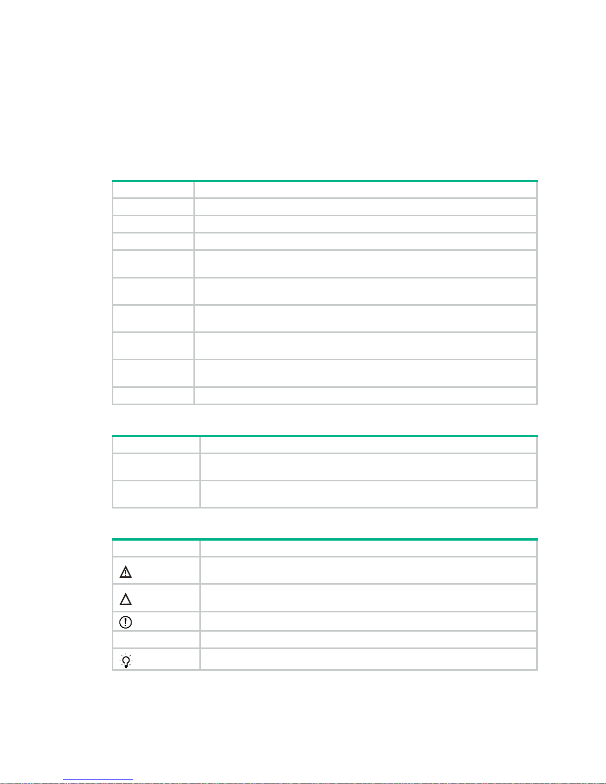
Document conventions and icons ······················································ 27
Conventions ··························································································································· 27
Network topology icons ············································································································· 28
Support and other resources ···························································· 29
Accessing Hewlett Packard Enterprise Support ·············································································· 29
Accessing updates ··················································································································· 29
Websites ························································································································· 30
Customer self repair ··········································································································· 30
Remote support ················································································································ 30
Documentation feedback ···································································································· 30
Index ··························································································· 32
Page 4

1
IRF commands
chassis convert mode irf
Use chassis convert mode irf to enable IRF mode.
Use undo chassis convert mode to restore the default.
Syntax
chassis convert mode irf
undo chassis convert mode
Default
The device operates in standalone mode.
Views
System view
Predefined user roles
network-admin
Usage guidelines
To set up an IRF fabric, place all member devices in IRF mode after you configure member IDs,
priorities, and IRF port settings for the member devices. In standalone mode, a device cannot form
an IRF fabric with other devices.
IRF generates packets on a device in IRF mode even if the device does not form an IRF fabric with
any other devices. To conserve system resources, set a device to standalone mode after removing it
from an IRF fabric.
Examples
# Enable IRF mode.
<Sysname> system-view
[Sysname] chassis convert mode irf
The device will switch to IRF mode and reboot.
You are recommended to save the current running configuration and specify the configuration
file for the next startup. Continue? [Y/N]:y
Do you want to convert the content of the next startup configuration file flash:/startup.cfg
to make it available in IRF mode? [Y/N]:y
Now rebooting, please wait...
# Restore standalone mode.
<Sysname> system-view
[Sysname] undo chassis convert mode
The device will switch to stand-alone mode and reboot.
You are recommended to save the current running configuration and specify the configuration
file for the next startup. Continue? [Y/N]:y
Do you want to convert the content of the next startup configuration file flash:/startup.cfg
to make it available in stand-alone mode? [Y/N]:y
Now rebooting, please wait...
Page 5

2
display irf
Use display irf to display IRF fabric information, including the member ID, role, priority, bridge MAC
address, and description of each IRF member.
Syntax
display irf
Views
Any view
Predefined user roles
network-admin
network-operator
Examples
# Display IRF fabric information.
<Sysname> display irf
MemberID Slot Role Priority CPU-Mac Description
*+1 0 Master 1 0000-0066-1600 -- 1 1 Standby 1 0000-0066-1601 ---
------------------------------------------------- * indicates the device is the master.
+ indicates the device through which the user logs in.
The bridge MAC of the IRF is: 0023-89b6-e58a
Auto upgrade : yes
Mac persistent : always
Domain ID : 0
Auto merge : yes
Table 1 Command output
Field Description
MemberID
IRF member ID:
• ID of the master is prefixed with an asterisk (*) sign.
• ID of the device where you are logged in is prefixed with a plus (+)
sign.
Slot MPU slot number.
Role
Role of the MPU in the IRF fabric:
• Standby—Standby MPU for the global active MPU.
• Master—Global active MPU.
• Loading—Standby MPU for the global active MPU. The standby
MPU is loading software images.
Priority IRF member priority.
CPU-MAC MAC address of the CPU on the MPU.
Page 6

3
Field Description
Description
Description you have configured for the member device:
• If no description is configured, this field displays a dashed line
(-----).
• If the description exceeds the maximum number of characters that
can be displayed, an ellipsis (…) is displayed in place of the
exceeding text. To display the complete description, use the
display current-configuration command.
Auto upgrade
Status of the software auto-update feature:
• yes—Enabled.
• no—Disabled.
MAC persistent
IRF bridge MAC persistence setting:
• 6 min—Bridge MAC address of the IRF fabric remains unchanged
for 6 minutes after the address owner leaves.
• always—Bridge MAC address of the IRF fabric does not change
after the address owner leaves.
• no—Bridge MAC address of the current master replaces the
original bridge MAC address as soon as the owner of the original
address leaves.
Auto merge
State of the auto-merge feature:
• yes—Enabled. The IRF fabric automatically reboots its member
devices when it fails in the master election during an IRF fabric
merge.
• no—Disabled. Manual reboot is required to complete an IRF fabric
merge.
Related commands
display irf configuration
display irf topology
display irf configuration
Use display irf configuration to display basic IRF settings, including each member's current
member ID, new member ID, and physical interfaces bound to the IRF ports. The new member IDs
take effect at reboot.
Syntax
display irf configuration
Views
Any view
Predefined user roles
network-admin
network-operator
Examples
# (In standalone mode.) Display the basic IRF settings of the device.
<Sysname> display irf configuration
MemberID Priority IRF-Port1 IRF-Port2
1 1 disable disable
# (In IRF mode.) Display basic IRF settings for all members.
Page 7

4
<Sysname> display irf configuration
MemberID NewID IRF-Port1 IRF-Port2
1 1 Ten-GigabitEthernet1/3/1/0 disable
Ten-GigabitEthernet1/3/1/1
2 2 disable Ten-GigabitEthernet2/2/1/0
Ten-GigabitEthernet2/2/1/1
Table 2 Command output
Field Description
MemberID Current member ID of the device.
Priority
Member priority.
This field is available when the device is operating in standalone mode.
NewID
Member ID assigned to the device. This member ID takes effect at reboot.
This field is available when the device is operating in IRF mode.
IRF-Port1
Physical interfaces bound to IRF-port 1.
This field displays
disable
if no physical interfaces are bound to the IRF port.
IRF-Port2
Physical interfaces bound to IRF-port 2.
This field displays
disable
if no physical interfaces are bound to the IRF port.
Related commands
display irf
display irf topology
display irf link
Use display irf link to display IRF link information.
Syntax
display irf link
Views
Any view
Predefined user roles
network-admin
network-operator
Examples
# Display IRF link information.
<Sysname> display irf link
Member 1
IRF Port Interface Status
1 disable - 2 GigabitEthernet1/2/1/1 UP
Member 2
IRF Port Interface Status
1 GigabitEthernet2/2/1/1 UP
2 disable --
Page 8

5
Table 3 Command output
Field Description
Member ID IRF member ID.
IRF Port
IRF port number:
• 1—IRF-port 1.
• 2—IRF-port 2.
Interface
Physical interfaces bound to the IRF port. This field displays
disable
if no
physical interfaces have been bound to the IRF port.
Status
Link state of the IRF physical interface:
• UP—The link is up.
• DOWN—The link is down.
• ADM—The interface has been manually shut down by using the
shutdown command.
• ABSENT—Interface module that hosts the interface is not present.
display irf topology
Use display irf topology to display IRF fabric topology information, including the member IDs, IRF
port state, adjacencies of IRF ports, and CPU MAC address of the master.
Syntax
display irf topology
Views
Any view
Predefined user roles
network-admin
network-operator
Examples
# Display the IRF fabric topology.
<Sysname> display irf topology
Topology Info
------------------------------------------------------------------------ IRF-Port1 IRF-Port2
MemberID Link neighbor Link neighbor Belong To
1 DOWN --- UP 2 0000-0066-1600
2 UP 1 DOWN --- 0000-0066-1600
Table 4 Command output
Field Description
IRF-Port1 Information about IRF-port 1, including its link state and neighbor.
IRF-Port2 Information about IRF-port 2, including its link state and neighbor.
MemberID IRF member ID.
Page 9

6
Field Description
Link
Link state of the IRF port:
• UP—The IRF link is up.
• DOWN—The IRF link is down because the port does not have a
reachable physical link or has not been activated by the
irf-port-configuration active command.
• DIS—No physical interfaces have been bound to the IRF port.
• TIMEOUT—IRF hello interval has timed out.
• ISOLATE—The device is isolated from the IRF fabric. This issue might be
caused by the following reasons:
{ The IRF fabric does not support the device model.
{ The maximum number of member devices has exceeded the upper
limit.
neighbor
IRF member ID of the device connected to the IRF port.
This field displays three hyphens (---) if no device is connected to the port.
Belong To
IRF fabric that has the device, represented by the CPU MAC address of the
master in the IRF fabric.
Related commands
display irf
display irf configuration
display irf-port load-sharing mode
Use display irf-port load-sharing mode to display IRF link load sharing mode information.
Syntax
display irf-port load-sharing mode
Views
Any view
Predefined user roles
network-admin
network-operator
Examples
# Display IRF link load sharing mode information for IRF links. In this example, because no
user-defined IRF link load sharing mode has been configured, the default load sharing mode applies.
<Sysname> display irf-port load-sharing mode
irf-port Load-Sharing Mode:
Layer 3 traffic: destination-ip address source-ip address
Layer 4 traffic: destination-port source-port
# Display IRF link load sharing mode for IRF links. In this example, because a link load sharing mode
based on source and destination MAC addresses has been configured, the configured mode
applies.
<Sysname> display irf-port load-sharing mode
irf-port Load-Sharing Mode:
destination-mac address source-mac address
Page 10

7
Table 5 Command output
Field Description
irf-port Load-Sharing Mode
IRF link load sharing mode:
• If no IRF link load sharing mode has been configured, the
default load sharing mode applies.
• If a user-defined load sharing mode has been configured,
the configured mode applies.
Layer 3 traffic: destination-ip address,
source-ip address
Default load sharing mode for non-TCP/-UDP IP packets. By
default, this type of traffic is distributed based on source and
destination IP addresses.
Layer 4 traffic: destination-port,
source-port
Default load sharing mode for TCP/UDP packets. By default, this
type of traffic is distributed based on source and destination port
numbers.
destination-mac address source-mac
address
User-defined load sharing mode. Traffic is distributed based on
source and destination MAC addresses.
display mad
Use display mad to display MAD status and settings.
Syntax
display mad [ verbose ]
Views
Any view
Predefined user roles
network-admin
network-operator
Parameters
verbose: Displays detailed MAD information. If you do not specify this keyword, the command only
displays whether a MAD mechanism is enabled or disabled.
Examples
# Display brief MAD information.
<Sysname> display mad
MAD ARP disabled.
MAD ND disabled.
MAD LACP disabled.
MAD BFD enabled.
# Display detailed MAD information.
<Sysname> display mad verbose
Multi-active recovery state: No
Excluded ports(user-configured):
Ten-GigabitEthernet2/2/1/2
Ten-GigabitEthernet2/2/1/3
Excluded ports(system-configured):
Ten-GigabitEthernet2/2/1/1
Ten-GigabitEthernet3/2/1/1
Page 11

8
MAD ARP disabled.
MAD ND disabled.
MAD LACP enabled interface: Route-Aggregation2
MAD status : Normal
Member ID Port MAD status
1 Ten-GigabitEthernet1/2/1/1 Normal
2 Ten-GigabitEthernet2/2/1/1 Normal
MAD BFD enabled interface: Route-Aggregation2
MAD status : Normal
Member ID MAD IP address Neighbor MAD status
1 192.168.1.1/24 2 Normal
2 192.168.1.2/24 1 Normal
Table 6 Command output
Field Description
MAD ARP disabled. Status of ARP MAD. This field is not supported in the current software version.
MAD ND disabled. Status of ND MAD. This field is not supported in the current software version.
Multi-active recovery state
Whether the IRF fabric is in Recovery state:
• Yes—The IRF fabric is in Recovery state. When MAD detects that an IRF
fabric has split into multiple IRF fabrics, it allows one fabric to forward
traffic. All the other IRF fabrics are set to the Recovery state. In Recovery
state, MAD shuts down all service interfaces in the fabric except for the
following service interfaces:
{ IRF physical interfaces.
{ Service interfaces configured to not shut down.
• No—The IRF fabric is not in Recovery state. It is active and can forward
traffic.
Excluded
ports(user-configured)
Service interfaces manually configured to not shut down when the IRF fabric
transits to the Recovery state.
Excluded
ports(system-configured)
Service interfaces set to not shut down by default when the IRF fabric transits
to the Recovery state. These service interfaces are not user configurable.
MAD status
MAD operating status:
• Normal—The MAD mechanism is operating correctly.
• Faulty—The MAD mechanism is not operating correctly. Check the
interface or port for connectivity or configuration problems. For example,
verify that all member devices have member ports used for LACP MAD.
• N/A—MAD link status cannot be detected.
Member ID IRF member ID of the local device.
Port Member ports of the aggregate interface used for LACP MAD.
Neighbor IRF member ID of the neighbor member device.
easy-irf
Use easy-irf to bulk-configure basic IRF settings for an IRF member device in IRF mode.
Syntax
easy-irf [ member member-id [ renumber new-member-id ] domain domain-id [ priority priority ]
[ irf-port1 interface-list1 ] [ irf-port2 interface-list2 ] ]
Page 12

9
Views
System view
Predefined user roles
network-admin
Parameters
member member-id: Specifies the member ID of a member device. The member ID must be 1 or 2.
renumber new-member-id: Specifies a new member ID for the device. The member I D must be 1 or
2. The member device automatically reboots for the new member ID to take effect. If you do not
specify this option, the command does not change the member ID.
domain domain-id: Specifies an IRF domain ID in the range of 0 to 4294967295. Assign the same
domain ID to all devices you are adding to the same IRF fabric.
priority priority: Specifies an IRF priority in the range of 1 to 32. The greater the priority value, the
higher the priority. A member with higher priority is more likely to be the master.
irf-port1 interface-list1: Specifies a space-separated list of up to eight interface items. Each interface
item specifies one interface in the interface-type interface-number form. The interfaces are bound to
IRF-port 1.
irf-port2 interface-list2: Specifies a space-separated list of up to eight interface items. Each interface
item specifies one interface in the interface-type interface-number form. The interfaces are bound to
IRF-port 2. A physical interface can be bound to only one IRF port.
Usage guidelines
This command bulk-configures basic IRF settings for a device in IRF mode, including the member ID,
domain ID, priority, and IRF port bindings.
The easy IRF feature provides the following configuration methods:
• Interactive method—Enter the easy-irf command without parameters. The system will guide
you to set the parameters step by step.
• Non-interactive method—Enter the easy-irf command with parameters.
As a best practice, use the interactive method if you are new to IRF.
If you execute this command multiple times, the following settings take effect:
• The most recent settings for the member ID, domain ID, and priority.
• IRF port bindings added through executions of the command. You can bind a maximum of eight
physical interfaces to an IRF port.
When you specify physical interfaces for an IRF port, you must follow the IRF port binding
requirements in Virtual Technologies Configuration Guide.
If you specify physical interfaces by using the interactive method, you must also follow these
restrictions and guidelines:
• Do not enter spaces between the interface type and interface number.
• Use a comma (,) to separate two physical interfaces. No spaces are allowed bet ween
interfaces.
To remove an IRF physical interface from an IRF port, you must use the undo port group interface
command in IRF port view .
Examples
# Bulk-configure basic IRF settings by using the non-interactive method.
<Sysname> system-view
[Sysname] easy-irf member 2 renumber 1 domain 10 priority 10 irf-port1 gigabitethernet
2/2/1/0
Page 13

10
*****************************************************************************
Configuration summary for member 2
IRF new member ID: 1
IRF domain ID : 10
IRF priority : 10
IRF-port 1 : GigabitEthernet2/2/1/0
IRF-port 2 : Disabled
*****************************************************************************
Are you sure to use these settings to set up IRF? [Y/N] y
Starting to configure IRF...
Configuration succeeded.
The device will reboot for the new member ID to take effect. Continue? [Y/N] y
# Bulk-configure basic IRF settings by using the interactive method.
<Sysname> system-view
[Sysname] easy-irf
*****************************************************************************
Welcome to use easy IRF.
To skip the current step, enter a dot sign (.).
To return to the previous step, enter a minus sign (-).
To use the default value (enclosed in []) for each parameter, press Enter without
entering a value.
To quit the setup procedure, press CTRL+C.
*****************************************************************************
Select a member by its ID <1> [1]: 1
Specify a new member ID <1~2> [1]: 2
Specify a domain ID <0~4294967295> [0]: 10
Specify a priority <1~32> [1]: 10
Specify IRF-port 1 bindings (a physical interface or a comma-separated physical
interface list)[Disabled]: gigabitethernet1/2/1/0
Specify IRF-port 2 bindings (a physical interface or a comma-separated physical
interface list)[Disabled]:
*****************************************************************************
Configuration summary for member 1
IRF new member ID: 2
IRF domain ID : 10
IRF priority : 10
IRF-port 1 : GigabitEthernet1/2/1/0
IRF-port 2 : Disabled
*****************************************************************************
Are you sure to use these settings to set up IRF? [Y/N] y
Starting to configure IRF...
Configuration succeeded.
The device will reboot for the new member ID to take effect. Continue? [Y/N] y
irf auto-merge enable
Use irf auto-merge enable to enable IRF auto-merge. This command enables an IRF fabric to
automatically reboot its member devices if it fails in the master election during an IRF fabric merge.
Page 14

11
Use undo irf auto-merge enable to disable IRF auto-merge.
Syntax
irf auto-merge enable
undo irf auto-merge enable
Default
IRF auto-merge is enabled. The IRF fabric that has failed in the master election reboots
automatically to complete the IRF fabric merge.
Views
System view
Predefined user roles
network-admin
Usage guidelines
For a successful merge, make sure IRF auto-merge is enabled on b oth IRF fabrics that are merging.
This command is supported only in IRF mode. When you change the operating mode from IRF to
standalone, the setting for this command is lost, regardless of whether you have saved the
configuration. To disable IRF auto-merge after you change the operating mode from standalone to
IRF, use the undo form of this command.
IRF auto-merge takes effect on merges caused by any of the following events:
• The IRF link recovers from a link failure.
• The IRF physical interfaces of the member devices are connected after the interfaces are
bound to IRF ports.
The feature does not take effect on a merge that occurs in the following conditions:
• You bind a physical interface to an IRF port.
• The interface has been connected to the peer IRF physical interface before the binding
operation.
If the IRF auto-merge feature does not take effect, you must save the running configuration, and then
follow the system instructions to manually reboot one or multiple member devices.
Examples
# Enable IRF auto-merge.
<Sysname> system-view
[Sysname] irf auto-merge enable
irf auto-update enable
Use irf auto-update enable to enable the software auto-update feature.
Use undo irf auto-update enable to disable the software auto-update feature.
Syntax
irf auto-update enable
undo irf auto-update enable
Default
Software auto-update is enabled.
Views
System view
Page 15

12
Predefined user roles
network-admin
Usage guidelines
This command is supported only in IRF mode. When you change the operating mode from IRF to
standalone, the setting for this command is lost, regardless of whether you have saved the
configuration. To disable software auto-update after you change the operating mode from
standalone to IRF, use the undo form of this command.
This command automatically propagates the current software images of the master MPU in the IRF
fabric to any MPUs you are adding to the IRF fabric.
To ensure a successful software update, verify that the new MPU you are adding to the IRF fabric
has sufficient storage space for the new software images. If sufficient storage sp ace is not available,
the system automatically deletes the current software images of the MPU. If the reclaimed space is
still insufficient, the MPU cannot complete the auto-update. You must reboot the device that holds
the MPU, and then access the BootWare menus to delete files.
You must manually update the new MPU with the software images running on the IRF fabric when
software auto-update is disabled.
Examples
# Enable the software auto-update feature.
<Sysname> system-view
[Sysname] irf auto-update enable
irf domain
Use irf domain to assign a domain ID to the IRF fabric.
Use undo irf domain to restore the default IRF domain setting.
Syntax
irf domain domain-id
undo irf domain
Default
The IRF domain ID is 0.
Views
System view
Predefined user roles
network-admin
Parameters
domain-id: Specifies a domain ID for the IRF fabric. The value range is 0 to 4294967295.
Usage guidelines
This command is supported only in IRF mode. When you change the operating mode from IRF to
standalone, the IRF domain setting is lost, regardless of whether you have saved the configuration.
One IRF fabric forms one IRF domain. IRF uses IRF domain IDs to uniquely identify IRF fabrics and
prevent IRF fabrics from interfering with one another.
An IRF fabric has only one IRF domain ID. You can change the IRF domain ID by using the irf
domain or mad enable command. The IRF domain IDs configured by using the commands
overwrite each other.
Page 16

13
Examples
# Set the IRF domain ID to 10.
<Sysname> system-view
[Sysname] irf domain 10
irf link-delay
Use irf link-delay to set a delay for the IRF ports to report a link down event.
Use undo irf link-delay to restore the default.
Syntax
irf link-delay interval
undo irf link-delay
Default
The delay is 1000 milliseconds.
Views
System view
Predefined user roles
network-admin
Parameters
interval: Sets the IRF link down report delay in the range of 0 to 10000 milliseconds. If the interval is
set to 0, link down events are reported without any delay.
Usage guidelines
This command is supported only in IRF mode. When you change the operating mode from IRF to
standalone, the command configuration is lost, regardless of whether you have saved the
configuration.
If the BFD feature is used in the IRF fabric, make sure the delay interval is shorter than the BFD
session lifetime. For more information about BFD, see High Availability Configuration Guide.
Examples
# Set the IRF link down report delay to 300 milliseconds.
<Sysname> system-view
[Sysname] irf link-delay 300
irf mac-address persistent
Use irf mac-address persistent to configure IRF bridge MAC persistence.
Use undo ir f mac-address persistent to enable the IRF fab ric to change its bridge MAC address as
soon as the address owner leaves.
Syntax
irf mac-address persistent { always | timer }
undo irf mac-address persistent
Default
The IRF bridge MAC address does not change after the address owner leaves the IRF fabric.
Page 17

14
Views
System view
Predefined user roles
network-admin
Parameters
always: Enables the IRF bridge MAC address to be permanent. The IRF bridge MAC addre ss does
not change after the address owner leaves the fabric.
timer: Enables the IRF bridge MAC address to remain unchanged for 6 minutes after the address
owner leaves. If the owner rejoins the IRF fabric with the time limit, the IRF bridge MAC addre ss does
not change. If the owner does not rejoin the IRF fabric within the time limit, the IRF fabric uses the
bridge MAC address of the current master as the bridge MAC address.
Usage guidelines
IRF bridge MAC persistence specifies the amount of time an IRF fabric can continue using a bridge
MAC address as its bridge MAC address after the address owner leaves.
Bridge MAC persistence is supported only in IRF mode. When you change the operating mode from
IRF to standalone, the bridge MAC persistence setting is lost, regardless of whether you have saved
the configuration.
If the IRF fabric has cross-member aggregate links, do not use the undo irf mac-address
persistent command.
By default, an IRF fabric uses the bridge MAC address of the master device as its bridge MAC
address. Layer 2 protocols, such as LACP, use this bridge MAC address to identify the IRF fabric. On
a switched LAN, the bridge MAC address must be unique.
To avoid duplicate bridge MAC addresses, an IRF fabric can change its bridge MAC address
automatically after the address owner leaves. However, the change causes temporary service
disruption. Depending on the network condition, you can enable the IRF fabric to retain or change its
bridge MAC address after the address owner leaves.
When IRF fabrics merge, IRF ignores the IRF bridge MAC address and checks the bridge MAC
address of each member device in the IRF fabrics. IRF merge fails if any two member devices have
the same bridge MAC address.
Examples
# Enable the IRF bridge MAC address to persist forever.
<Sysname> system-view
[Sysname] irf mac-address persistent always
irf member
Use irf member to assign a member ID to the device in standalone mode.
Use undo irf member to restore the default.
Syntax
irf member member-id
undo irf member
Default
The member ID is 1.
Views
System view
Page 18

15
Predefined user roles
network-admin
Parameters
member-id: Assigns an IRF member ID to the device. The member ID must be 1 or 2.
Usage guidelines
Assign an IRF member ID to a device before enabling IRF mode. The member ID takes effect after
IRF mode is enabled. This member ID must be unique among all IRF member device s.
To change the member ID of a device in IRF mode, use the irf member renumber command. The
new member ID takes effect at reboot.
Examples
# (In standalone mode.) Assign member ID 2 to the device.
<Sysname> system-view
[Sysname] irf member 2
Related commands
irf member renumber
irf member description
Use irf member description to configure a description for an IRF member.
Use undo irf member description to restore the default.
Syntax
irf member member-id description text
undo irf member member-id description
Default
No description is configured for an IRF member.
Views
System view
Predefined user roles
network-admin
Parameters
member-id: Specifies the ID of an IRF member. The member ID must be 1 or 2.
text: Configures the IRF member description, a string of 1 to 127 characters.
Usage guidelines
Configure a description to describe the location or purpose of a member device.
This command is supported only in IRF mode. When you change the operating mode from IRF to
standalone, the IRF member description is lost, regardless of whether you have saved the
configuration.
Examples
# Configure a description for IRF member 1.
<Sysname> system-view
[Sysname] irf member 1 description F1Num001
Page 19

16
irf member priority
Use irf member priority to change the priority of an IRF member device in IRF mode.
Use undo irf member priority to restore the default.
Syntax
irf member member-id priority priority
undo irf member member-id priority
Default
The IRF member priority is 1.
Views
System view
Predefined user roles
network-admin
Parameters
member-id: Specifies an IRF member ID. The member ID must be 1 or 2.
priority: Sets priority in the range of 1 to 32. The greater the priority value, the higher the priority. A
member with higher priority is more likely to be the master.
Usage guidelines
This command is supported only in IRF mode. The new priority setting takes effect at the next master
election, but it does not trigger a master election.
To assign an IRF priority to a device in standalone mode, use the irf priority command.
To display the ID and priority settings of IRF members, use the display irf command.
Examples
# (In IRF mode.) Set the priority of IRF member 2 to 32.
<Sysname> system-view
[Sysname] irf member 2 priority 32
Related commands
irf priority
irf member renumber
Use irf member renumber to change the IRF member ID of a device in IRF mode.
Use undo irf member renumber to restore the previous IRF member ID of the device.
Syntax
irf member member-id renumber new-member-id
undo irf member member-id renumber
Default
The device uses the member ID that is set in standalone mode.
Views
System view
Page 20

17
Predefined user roles
network-admin
Parameters
member-id: Specifies the ID of an IRF member. The member ID must be 1 or 2.
new-member-id: Assigns a new ID to the IRF member. The memb er ID must be 1 or 2.
Usage guidelines
CAUTION:
IRF member ID change can cause losses of member ID-related sett ings at reboot, including settings
on IRF physical interfaces.
To have the new ID take effect, you must reboot the IRF member. To cancel the member ID change
before you reboot the member device, use the undo irf member renumber command. In the
command, set the new member ID to be the same as the old member ID.
When adding a device into an IRF fabric, you must assign a unique IRF member ID to the device. If
its IRF member ID has been used in the IRF fabric, the device cannot join the IRF fabric.
Plan IRF member ID assignment before setting up an IRF fabric, and change member IDs before
configuring any other features.
Interchanging member IDs between IRF member devices might cause undesirable configuration
changes and data loss. For example, the IRF member IDs of Device A and Device B are 1 and 2,
respectively. After you interchange their member IDs, their port settings also interchange.
After an IRF fabric is formed, make sure you understand the impact of the member ID change on
your network.
To set the member ID of a device in standalone mode, use the irf member command.
Examples
# (In IRF mode.) Change the ID of an IRF member from 2 to 1.
<Sysname> display irf
[Sysname] irf member 2 renumber 1
Renumbering the member ID may result in configuration change or loss. Continue?[Y/N]Y
# (In IRF mode.) Before rebooting the device, cancel the change in the preceding example.
[Sysname] undo irf member 2 renumber
Renumbering the member ID may result in configuration change or loss. Continue?[Y/N]y
If you reboot the device after executing the irf member 2 renumber 1 command, the device member
ID changes to 1 at system reboot. Using undo irf member 2 renumber cannot restore th e member
ID to 2. You must use the irf member 1 renumber 2 command to reconfigure the member ID.
Related commands
irf member
irf priority
Use irf priority to assign an IRF member priority to a device in standalone mode.
Use undo irf priority to restore the default.
Syntax
irf priority priority
undo irf priority
Page 21

18
Default
The IRF member priority is 1.
Views
System view
Predefined user roles
network-admin
Parameters
priority: Specifies an IRF member priority value in the range of 1 to 32. The greater the priority value,
the higher the priority. A member with higher priority is more likely to be the master.
Usage guidelines
The member priority configured in standalone mode takes ef fect after you enable IRF mode.
To change the member priority of a device in IRF mode, use the irf member priority command. The
new priority setting takes effect at the next master election, but it does not trigger a master election.
Examples
# (In standalone mode.) Assign IRF member priority 32 to the device.
[Sysname] system-view
[Sysname] irf priority 32
Related commands
irf member priority
irf-port
Use irf-port to enter IRF port view.
Use undo irf-port to remove all port bindings on an IRF port.
Syntax
In standalone mode:
irf-port irf-port-number
undo irf-port irf-port-number
In IRF mode:
irf-port member-id/irf-port-number
undo irf-port member-id/irf-port-number
Views
System view
Predefined user roles
network-admin
Parameters
member-id: Specifies an IRF member device by its member ID.
irf-port-number: Specifies an IRF port on the member device. The irf-port-number argument
represents the IRF port index and must be 1 or 2.
Usage guidelines
To bind physical interfaces to an IRF port, you must enter IRF port view.
Page 22

19
Before you remove all port bindings on an IRF port, shut down all its physical interfaces.
Examples
# (In standalone mode.) Enter IRF-port 1 view.
<Sysname> system-view
[Sysname] irf-port 1
[Sysname-irf-port1]
# (In IRF mode.) Enter IRF-port 3/1 view.
<Sysname> system-view
[Sysname] irf-port 3/1
[Sysname-irf-port3/1]
Related commands
port group interface
irf-port global load-sharing mode
Use irf-port global load-sharing mode to set the IRF link load sharing mode for IRF links.
Use undo irf-port global load-sharing mode to restore the default.
Syntax
irf-port global load-sharing mode { destination-ip | destination-mac | ingress-port | source-ip |
source-mac } *
undo irf-port global load-sharing mode
Default
The following are criteria for distributing different types of packet s across IRF lin ks:
• TCP/UDP packets—Source and destination TCP/UDP port numbers.
• Non-TCP/-UDP IP packets—Source and destination IP addresses.
Views
System view
Predefined user roles
network-admin
Parameters
destination-ip: Distributes traffic across IRF member links based on destination IP address.
destination-mac: Distributes packets across IRF member links based on de stination MAC address.
ingress-port: Distributes packets across IRF member links based on incoming port.
source-ip: Distributes packets across IRF member links based on source IP address.
source-mac: Distributes packets across IRF member links based on source MAC address.
Usage guidelines
The IRF link load sharing mode applies to all IRF ports in the IRF fabric. You can configure the
sharing mode to include a combination of multiple criteria for making traffic distribution decisions.
(For example, criteria could include source MAC address and IP address.) If your device does not
support a criterion combination, the system displays an error message.
If you configure the IRF link load sharing mode multiple times, the most recent configuration takes
effect.
Page 23

20
Examples
# Configure the IRF link load sharing mode to distribute traffic based on destination MAC address.
<Sysname> system-view
[Sysname] irf-port global load-sharing mode destination-mac
irf-port-configuration active
Use irf-port-configuration active to activate IRF port settings.
Syntax
irf-port-configuration active
Views
System view
Predefined user roles
network-admin
Usage guidelines
After connecting the physical interfaces between two devices and binding them to the correct IRF
ports, you must use this command to activate the settings on the IRF ports. This command merges
the two devices into one IRF fabric.
The system activates the IRF port settings automatically in the following situations:
• The configuration file that the device starts with contains IRF port bindings.
• You are binding physical interfaces to an IRF port after an IRF fabric is formed.
Examples
To configure and activate IRF-port 1/2 when the port is in DIS state:
# Bind Ten-GigabitEthernet 1/2/1/1 to IRF-port 1/2.
<Sysname> system-view
[Sysname] interface ten-gigabitEthernet 1/2/1/1
[Sysname-Ten-GigabitEthernet1/2/1/1] shutdown
[Sysname-Ten-GigabitEthernet1/2/1/1] quit
[Sysname] irf-port 1/2
[Sysname-irf-port1/2] port group interface Ten-GigabitEthernet 1/2/1/1
Info : You are recommended to save the configuration now; otherwise, it will be lost after
system reboot.
[Sysname-irf-port1/2] quit
[Sysname] interface ten-gigabitEthernet 1/2/1/1
[Sysname-Ten-GigabitEthernet1/2/1/1] undo shutdown
[Sysname-Ten-GigabitEthernet1/2/1/1] quit
# Save the configuration so the IRF port settings can take effect after the device reboots.
[Sysname] save
The current configuration will be written to the device. Are you sure? [Y/N]:y
Please input the file name(*.cfg)[flash:/startup.cfg]
(To leave the existing filename unchanged, press the enter key):
flash:/startup.cfg exists, overwrite? [Y/N]:y
Validating file. Please wait............................
Saved the current configuration to mainboard device successfully.
Chassis 1 Slot 1:
Page 24

21
Save next configuration file successfully.
Configuration is saved to device successfully.
# Activate the IRF port settings.
[Sysname] irf-port-configuration active
mad bfd enable
Use mad bfd enable to enable BFD MAD.
Use undo mad bfd enable to disable BFD MAD.
Syntax
mad bfd enable
undo mad bfd enable
Default
BFD MAD is disabled.
Views
Layer 3 interface view
Predefined user roles
network-admin
Usage guidelines
BFD MAD uses the BFD protocol to detect multi-active collisions. This MAD mechanism can work
with or without intermediate devices.
When you configure BFD MAD on a Layer 3 aggregate interface, follow these restrictions and
guidelines:
Category Restrictions and guidelines
BFD MAD-enabled Layer 3
aggregate interface
Make sure the IRF fabrics on the network use different BFD MAD-enabled
aggregate interfaces.
BFD MAD VLAN
On the intermediate device (if any), assign the ports on the BFD MAD links to
the same VLAN. Do not assign the ports to an aggregate interface.
BFD MAD-enabled Layer 3
aggregate interface and
feature compatibility
Configure only the
mad bfd enable
and
mad ip address
commands on the
BFD MAD-enabled interface. If you configure other features, both BFD MAD
and other features on the interface might run incorrectly.
MAD IP address
• To avoid problems, only use the mad ip address command to configure
IP addresses on the BFD MAD-enabled interface. Do not configure an IP
address by using the ip address command or configure a VRRP virtual
address on the BFD MAD-enabled interface.
• Make sure all the MAD IP addresses are on the same subnet.
Examples
# Enable BFD MAD on Route-Aggregation 3.
<Sysname> system-view
[Sysname] interface route-aggregation 3
[Sysname-Route-Aggregation3] mad bfd enable
Page 25

22
mad enable
Use mad enable to enable LACP MAD.
Use undo mad enable to disable LACP MAD.
Syntax
mad enable
undo mad enable
Default
LACP MAD is disabled.
Views
Aggregate interface view
Predefined user roles
network-admin
Usage guidelines
LACP MAD uses extended LACP packets to detect multi-active collisions. This MAD mechanism
requires an intermediate device that supports extended LACPDUs.
You must set up a dynamic link aggregation group that spans all IRF member devices between the
IRF fabric and the intermediate device. To enable dynamic link aggregation, configure the
link-aggregation mode dynamic command on the aggregate interface.
If one IRF fabric uses another IRF fabric as the intermediate device for LACP MAD, you must assi gn
the two IRF fabrics different domain IDs for correct split detection. False detection causes IRF split.
When you use the mad enable command, the system prompts you to enter a domain ID. If you do
not want to change the current domain ID, press enter at the prompt.
NOTE:
An IRF fabric has only one IRF domain ID. You can change the IRF domain ID by using irf domain
or mad enable command. The IRF domain IDs configured by using the commands overwrite each
other.
Examples
# Enable LACP MAD on Route-Aggregation 1, a Layer 3 dynamic aggreg ate interface.
<Sysname> system-view
[Sysname] interface route-aggregation 1
[Sysname-Route-Aggregation1] link-aggregation mode dynamic
[Sysname-Route-Aggregation1] mad enable
You need to assign a domain ID (range: 0-4294967295)
[Current domain is: 0]: 1
The assigned domain ID is: 1
MAD LACP only enable on dynamic aggregation interface.
Related commands
irf domain
Page 26

23
mad exclude interface
Use mad exclude interface to excl ude a service interface from being shut down when the IRF fabric
transits to the Recovery state upon detection of a multi-active collision.
Use undo mad exclude interface to configure the I RF fabric to shut down a service interfa ce when
it transits to the Recovery state upon detection of a multi-active collision.
Syntax
mad exclude interface interface-type interface-number
undo mad exclude interface interface-type interface-number
Default
All service interfaces except for the IRF physical interfaces shut down when the IRF fabric transits to
the Recovery state.
Views
System view
Predefined user roles
network-admin
Parameters
interface-type interface-number: Specifies a service interface by its type and number.
Usage guidelines
If a service interface must be kept in up state for special purposes such as Telnet connection,
exclude the service interface from the shutdown action. As a best practice to avoid incorrect traffic
forwarding, do not exclude any service interfaces except for the service interfaces used for Telnet.
Do not exclude the aggregate interfaces used for MAD and their member ports from the shutdown
action.
The service interfaces that have been shut down by MAD come up when the member devices reboot
to join the recovered IRF fabric. If auto recovery fails because the current master fails or any other
exception occurs, use the mad restore command to manually recover the member devices and
bring up the service interfaces.
Examples
# Exclude GigabitEthernet 1/2/1/1 from being shut down when the MAD status transits to Recovery.
<Sysname> system-view
[Sysname] mad exclude interface gigabitethernet 1/2/1/1
Related commands
mad restore
mad ip address
Use mad ip address to assign a MAD IP address to an IRF member device for BFD MAD.
Use undo mad ip address to delete the MAD IP address for an IRF member device.
Syntax
mad ip address ip-address { mask | mask-length } member member-id
undo mad ip address ip-address { mask | mask-length } member member-id
Page 27

24
Default
No MAD IP address is configured for an IRF member device.
Views
Layer 3 interface view
Predefined user roles
network-admin
Parameters
ip-address: Specifies an IP address in dotted decimal notation. This IP address is bound to an IRF
member for BFD detection and is called a MAD IP address.
mask: Specifies a subnet mask in decimal dotted notation.
mask-length: Specifies a subnet mask in length, in the range of 0 to 32.
member member-id: Specifies the ID of an IRF member.
Usage guidelines
To use BFD MAD, configure a MAD IP address for each IRF member. Make sure all the MAD IP
addresses are on the same subnet.
Do not configure a MAD IP address by using the ip address command or configure a VRRP virtual
address on the BFD MAD-enabled interface.
The master attempts to establish BFD sessions with other member devices by using its MAD IP
address as the source IP address.
• If the IRF fabric is integrated, only the MAD IP address of the master takes effect. The master
cannot establish a BFD session with any other member. If you execute the display bfd
session command, the state of the BFD sessions is Down.
• When the IRF fabric splits, the IP addresses of the masters in the partitioned IRF fabrics take
effect. The masters can establish a BFD session. If you execute the display bfd session
command, the state of the BFD session between the two devices is Up.
Examples
# Assign a M A D IP address to IRF member 1 on Route-Aggregation 3.
<Sysname> system-view
[Sysname] interface route-aggregation 3
[Sysname-Route-Aggregation3] mad ip address 192.168.0.1 255.255.255.0 member 1
# Assign a M A D IP address to IRF member 2 on Route-Aggregation 3.
[Sysname-Route-Aggregation 3] mad ip address 192.168.0.2 255.255.255.0 member 2
Related commands
mad bfd enable
mad restore
Use mad restore to restore the normal MAD state of the IRF fabric in Recovery state.
Syntax
mad restore
Views
System view
Page 28

25
Predefined user roles
network-admin
Usage guidelines
If the active IRF fabric has failed to work before the IRF split problem is fixed, use this command to
restore an IRF fabric in Recovery state. The recovered IRF fabric will take over the active IRF fabric
role.
Examples
# Restore the normal MAD state of the IRF fabric in Recovery state.
<Sysname> system-view
[Sysname] mad restore
This command will restore the device from multi-active conflict state. Continue? [Y/N]:Y
Restoring from multi-active conflict state, please wait...
port group interface
Use port group interface to bind a physical interface to an IRF port.
Use undo port group interface to remove the binding of a physical interface to an IRF port.
Syntax
port group interface interface-type interface-number [ mode enhanced ]
undo port group interface interface-name
Default
No physical interfaces are bound to an IRF port.
Views
IRF port view
Predefined user roles
network-admin
Parameters
interface-type interface-number: Specifies a physical interface by its type and number.
interface-name: Specifies a physical interface in the interface-typeinterface-number format. No
space is allowed between the interface-type and interface-number arguments.
mode enhanced: Specifies the enhanced binding mode for the IRF physical interface. An IRF
physical interface operates in enhanced mode regardless of whether you have specified these
keywords.
Usage guidelines
Bind a minimum of one physical interface to an IRF port for setting up an IRF connection. You can
bind a maximum of eight physical interfaces to an IRF port.
In IRF mode, use the shutdown command to shut down a physical interface before you bind it to or
remove it from an IRF port. To bring up the physical interface after a binding or binding removal
operation, use the undo shutdown command.
In standalone mode, the shutdown and undo shutdown operations are not required.
The system does not dynamically remove IRF port bindings when IRF links are lost, for example,
because an interface card is removed. To remove IRF port bindings, you must use the undo port
group interface command.
Page 29

26
For more information about IRF port binding requirements, see Virtual Technologies Configuration
Guide.
Examples
# (In standalone mode.) Bind Ten-GigabitEthernet 2/1/1 to IRF-port 1.
<Sysname> system-view
[Sysname] irf-port 1
[Sysname-irf-port1] port group interface ten-gigabitethernet 2/1/1
# (In IRF mode.) Bind Ten-GigabitEthernet 1/2/1/1 to IRF-port 1/1 on IRF member 1.
<Sysname> system-view
[Sysname] interface ten-gigabitethernet 1/2/1/1
[Sysname-Ten-GigabitEthernet1/2/1/1] shutdown
[Sysname-Ten-GigabitEthernet1/2/1/1] quit
[Sysname] irf-port 1/1
[Sysname-irf-port 1/1] port group interface ten-gigabitethernet 1/2/1/1
[Sysname-irf-port 1/1] quit
[Sysname] interface ten-gigabitethernet 1/2/1/1
[Sysname-Ten-GigabitEthernet1/2/1/1] undo shutdown
Related commands
irf-port
Page 30
27
Document conventions and icons
Conventions
This section describes the conventions used in the documentation.
Command conventions
Convention Description
Boldface Bold
text represents commands and keywords that you enter literally as shown.
Italic
Italic text represents arguments that you replace with actual values.
[ ] Square brackets enclose syntax choices (keywords or arguments) that are optional.
{ x | y | ... }
Braces enclose a set of required syntax choices separated by vertical bars, from which
you select one.
[ x | y | ... ]
Square brackets enclose a set of optional syntax choices separated by vertical bars,
from which you select one or none.
{ x | y | ... } *
Asterisk marked braces enclose a set of required syntax choices separated by vertical
bars, from which you select at least one.
[ x | y | ... ] *
Asterisk marked square brackets enclose optional syntax choices separated by vertical
bars, from which you select one choice, multiple choices, or none.
&<1-n>
The argument or keyword and argument combination before the ampersand (&) sign
can be entered 1 to n times.
# A line that starts with a pound (#) sign is comments.
GUI conventions
Convention Description
Boldface
Window names, button names, field names, and menu items are in Boldface. For
example, the
New User
window opens; click OK.
>
Multi-level menus are separated by angle brackets. For example,
File
>
Create
>
Folder
.
Symbols
Convention Description
WARNING!
An alert that calls attention to important information that if not understood or followed
can result in personal injury.
CAUTION:
An alert that calls attention to important information that if not understood or followed
can result in data loss, data corruption, or damage to hardware or software.
IMPORTANT:
An alert that calls attention to essential information.
NOTE:
An alert that contains additional or supplementary information.
TIP:
An alert that provides helpful information.
Page 31
28
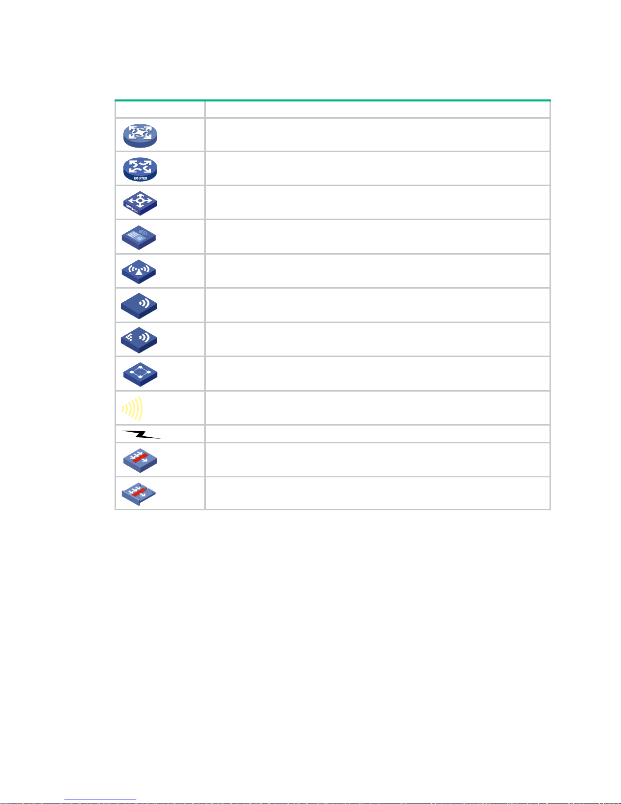
Network topology icons
Convention Description
Represents a generic network device, such as a router, switch, or firewall.
Represents a routing-capable device, such as a router or Layer 3 switch.
Represents a generic switch, such as a Layer 2 or Layer 3 switch, or a router that
supports Layer 2 forwarding and other Layer 2 features.
Represents an access controller, a unified wired-WLAN module, or the access
controller engine on a unified wired-WLAN switch.
Represents an access point.
Represents a wireless terminator unit.
Represents a wireless terminator.
Represents a mesh access point.
Represents omnidirectional signals.
Represents directional signals.
Represents a security product, such as a firewall, UTM, multiservice security
gateway, or load balancing device.
Represents a security module, such as a firewall, load balancing, NetStream, SSL
VPN, IPS, or ACG module.
Examples provided in this document
Examples in this document might use devices that differ from your device in hardware model,
configuration, or software version. It is normal that the port numbers, sample output, screenshots,
and other information in the examples differ from what you have on your device.
T
T
T
T
Page 32

29
Support and other resources
Accessing Hewlett Packard Enterprise Support
• For live assistance, go to the Contact Hewlett Packard Enterprise Worldwide web site:
www.hpe.com/assistance
• To access documentation and support services, go to the Hewlett Packard Enterprise Support
Center website:
www.hpe.com/support/hpesc
Information to collect
• Technical support registration number (if applicable)
• Product name, model or version, and serial number
• Operating system name and version
• Firmware version
• Error messages
• Product-specific reports and logs
• Add-on products or components
• Third-party products or components
Accessing updates
• Some software products provide a mechanism for accessing software updates through the
product interface. Review your product documentation to identify the recommended software
update method.
• To download product updates, go to either of the following:
{ Hewlett Packard Enterprise Support Center Get connected with updates page:
www.hpe.com/support/e-updates
{ Software Depot website:
www.hpe.com/support/softwaredepot
• To view and update your entitlements, and to link your contracts, Care Packs, and warranties
with your profile, go to the Hewlett Packard Enterprise Support Center More Information on
Access to Support Materials page:
www.hpe.com/support/AccessToSupportMaterials
IMPORTANT:
Access to some updates might require product entitlement when acce ssed through the Hewlett
Packard Enterprise Support Center. You must have an HP Passport set up with relevant
entitlements.
Page 33

30
Websites
Website Link
Networking websites
Hewlett Packard Enterprise Information Library for
Networking
www.hpe.com/networking/resourcefinder
Hewlett Packard Enterprise Networking website www.hpe.com/info/networking
Hewlett Packard Enterprise My Networking website www.hpe.com/networking/support
Hewlett Packard Enterprise My Networking Portal www.hpe.com/networking/mynetworking
Hewlett Packard Enterprise Networking Warranty www.hpe.com/networking/warranty
General websites
Hewlett Packard Enterprise Information Library www.hpe.com/info/enterprise/docs
Hewlett Packard Enterprise Support Center www.hpe.com/support/hpesc
Hewlett Packard Enterprise Support Services Central ssc.hpe.com/portal/site/ssc/
Contact Hewlett Packard Enterprise Worldwide www.hpe.com/assistance
Subscription Service/Support Alerts www.hpe.com/support/e-u pdates
Software Depot www.hpe.com/support/softwaredepot
Customer Self Repair (not applicable to all devices) www.hpe.com/support/selfrepair
Insight Remote Support (not applicable to all devices) www.hpe.com/info/insightremotesupport/docs
Customer self repair
Hewlett Packard Enterprise customer self repair (CSR) programs allow you to repair yo ur product. If
a CSR part needs to be replaced, it will be shipped directly to you so that you can install it at your
convenience. Some parts do not qualify for CSR. Your Hewlett Packard Enterprise authorized
service provider will determine whether a repair can be accomplished by CSR.
For more information about CSR, contact your local service provider or go to the CSR website:
www.hpe.com/support/selfrepair
Remote support
Remote support is available with supported devices as part of your warranty, Care Pack Service, or
contractual support agreement. It provides intelligent event diagnosis, and automatic, secure
submission of hardware event notifications to Hewlett Packard Enterprise, which will initiate a fast
and accurate resolution based on your product’s service level. Hewlett Packard Enterprise strongly
recommends that you register your device for remote support.
For more information and device support details, go to the following website:
www.hpe.com/info/insightremotesupport/docs
Documentation feedback
Hewlett Packard Enterprise is committed to providing documentation that meets your needs. To help
us improve the documentation, send any errors, suggestions, or comments to Documentation
Feedback (docsfeedback@hpe.com
). When submitting your feedback, include the document title,
Page 34

31
part number, edition, and publication date located on the front cover of the document. For online help
content, include the product name, product version, help edition, and publication date located on the
legal notices page.
Page 35

32
Index
C D E I M P
C
chassis convert mode irf,1
D
displ
ay irf,2
displ
ay irf configuration,3
displ
ay irf link,4
displ
ay irf topology,5
displ
ay irf-port load-sharing mode,6
displ
ay mad,7
E
easy-i
rf,8
I
irf auto-me
rge enable,10
irf auto-u
pdate enable,11
irf domain,12
irf link-delay
,13
irf mac-add
ress persistent,13
irf member
,14
irf member description,15
irf member priority
,16
irf membe
r renumber,16
irf priority
,17
irf-port,18
irf-po
rt global load-sharing mode,19
irf-po
rt-configuration active,20
M
mad bfd ena
ble,21
mad ena
ble,22
mad exclu
de interface,23
mad ip add
ress,23
mad re
store,24
P
port group int
erface,25
 Loading...