

Page 1
HPE MSA Controller
Module Replacement
About this document
• The SMU (Storage Management Utility) and the CLI
can be used to manage the enclosure. Tasks in this
document demonstrate using the SMU. Refer to the
SMU reference guide, or the CLI reference Guide for
instructions using those interfaces.
• For the latest product documentation, see the HPE
Support Center website http://www.hpe.com/
support/hpesc.
Instructions
Abstract
This document details procedures for replacing a failed
controller module in an HPE Modular Smart Array
system.
©
Copyright 2013, 2017 Hewlett Packard Enterprise Development LP
Before you begin
Observe the following:
CAUTION:
• Removing a module from an operational
enclosure significantly changes air flow within
the enclosure. Openings must be populated for
the enclosure to cool properly. Leave modules
in the enclosure until a replacement is
available.
• Parts can be damaged by electrostatic
discharge; use proper anti-static protection.
Keep parts in electrostatic containers until
needed and ensure you are properly grounded
when touching static-sensitive components.
IMPORTANT:
When replacing both controllers in an operational
enclosure, do as follows:
1. Replace one controller as detailed in these
instructions.
2. Wait 30 minutes. This pause ensures that the
controller and its ownership of the vdisks or
disk-groups have enough time to fully stabilize.
3. To ensure that the system is stable, check the
system status and event logs.
4. Replace the other controller as detailed in these
instructions.
Part Number: Q1J79-62018
Published: September 2017
Edition: 5
*Q1J79-62018*
IMPORTANT:
When two controllers are installed in an enclosure,
they must be the same model and the same
firmware version. Mixing controller types or
firmware versions in the same enclosure is not
supported.
Page 1
Page 2
To reduce the impact on system performance, perform
all maintenance tasks during periods of low system
activity or during a system maintenance window.
Note key settings using the SMU: Consult the SMU
guide for your model to determine how to obtain these
settings.
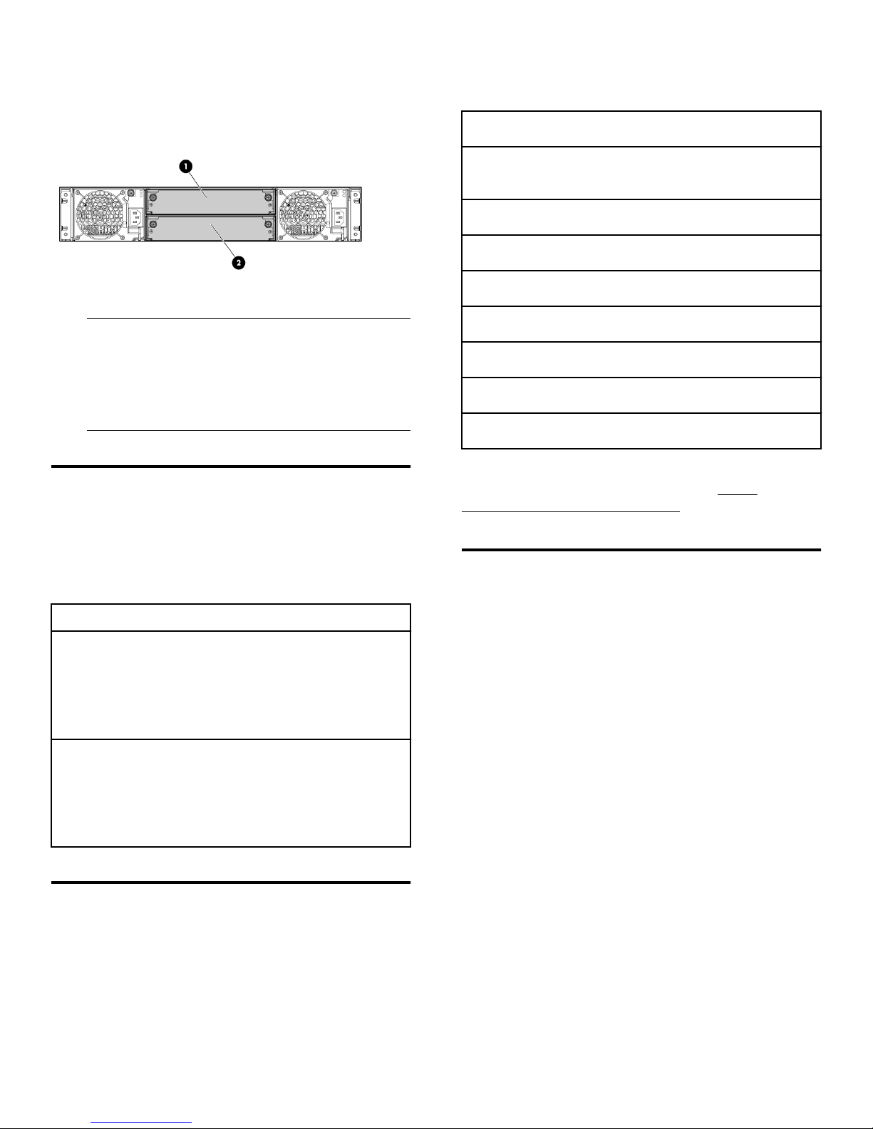
The following illustration shows controller module
locations.
1. Controller module A 2. Controller module B
NOTE:
Illustrations in this document show generic
representations of modules and enclosures;
procedures are the same for all modules shipped
with this document.
Verifying module failure
Before replacing the module, look at the event log,
system management utilities, and device LEDs, to
confirm that the module has failed.
Table 1: LED descriptions
NTP settings:
System information (name, contact, location, and
description):
User information:
Email notification settings:
SNMP notification settings:
syslog notification settings:
Scheduled tasks:
Hosts (IDs and names):
Specific host (IDs, names, and mappings):
For more information regarding these settings, see the
applicable MSA SMU documentation at: http://
www.hpe.com/info/storage/docs.
Partner Firmware Update (dual-controller
configurations only)
Module LED Description
FRU OK
Fault/Service
Required
• Solid Green = Module is operating
normally
• Blink = System is starting up
• Off = Module is not operating
normally
• Solid Amber = Fault condition
• Blinking Amber = Hardwarecontrolled power-up or cache flush/
restore error
• Off = No fault conditions
Recording configuration settings
As a best practice, record system settings before
replacing a controller module.
In a dual-controller configuration, the Partner Firmware
Update option ensures that both controllers have the
most recent version. For controller replacement on an
MSA P2000 array, Hewlett Packard Enterprise
recommends disabling this feature to avoid
unintentionally changing the firmware on the controller
not being replaced. For all other MSA arrays Hewlett
Packard Enterprise recommends leaving this setting
enabled during controller replacement.
After both controllers are running the desired firmware
version, Hewlett Packard Enterprise recommends
enabling this feature for future firmware upgrades. For
the MSA2040/1040 and MSA2050/1050 arrays, it is
highly recommended to have this setting enabled at all
times.
To view or change the current Partner Firmware
Update setting.
• In the MSA 1050/2050 SMU: In the system topic,
select Action > Update Firmware. The Update
Page 2
Page 3

Firmware panel opens, select (enable) the PFU
check box and confirm the action.
• In the P2000 SMU and MSA 1040/2040 SMU v2:
Configuration > Advanced Settings > Firmware. If
needed, check the box and click Apply.
• In CLI: # set advanced-settings partner-firmwareupgrade enabled.
Transporting CompactFlash (singlecontroller configurations only)
CAUTION:
In single-controller configurations, to prevent data
loss, the CompactFlash must be moved from the
failed controller to the new controller. In dualcontroller configurations, do not transport the
CompactFlash, as data corruption might occur.
Procedure
1. Make sure that transporting the cache is the
appropriate action to take as specified in the user
guide for your MSA model.
2. Carefully remove the CompactFlash from the
controller, label it Data, and set it aside.
• In a single-controller configuration, if
transporting the CompactFlash to a new
controller, remove the controller only after the
cache is copied to CompactFlash. When the
copy is complete, the Cache Status LED is off,
or it is flashing one-tenth of a second ON and
nine-tenths of a second OFF.
• In a single-controller environment, I/O must be
stopped and the enclosure must be powered off
prior to the replacement.
• In a dual-controller environment, if the failed
controller is first shut down, the controller may
be hot-replaced in an operational enclosure.
Procedure
1. If you are replacing a controller in a single-controller
environment, stop all I/O and remove power from the
enclosure. Go to step 3.
2. In a dual-controller configuration:
a. To shut down the failed controller:
• For the P2000 SMU and the MSA 1040/2040
SMU v2 — Select the system in the
Configuration View panel and then Tools >
Shut Down or Restart Controller.
• For the MSA 1050/2050 SMU and the MSA
1040/2040 SMU v3 — Select Restart System
from the System topic.
b. Set the following options and then click OK:
3. Carefully remove the CompactFlash from the new
controller and set it aside.
4. Insert into the new controller the CompactFlash that
you removed from the failed controller and labeled
Data.
Removing the failed controller module
IMPORTANT:
• Operation—Shut down
• Controller Type—Storage
• Controller—A or B
The blue OK to Remove LED on the controller
illuminates, indicating that the controller can be
safely removed.
c. Locate the enclosure in which the controller
module OK to Remove LED is blue.
3. Disconnect cables connected to the module. Label
each cable to facilitate reconnection.
4. Turn the thumbscrews until the screws disengage
from the module (1) and rotate both latches
downward to disengage the module from the internal
connector (2).
5. Pull the module straight out of the enclosure (3).
Page 3
Page 4

NOTE:
The illustration is for reference only. In a singlecontroller system, remove the controller module
from module A, top location.
After installing a controller in an operational, dualcontroller system, the new controller automatically
begins initializing. If the firmware versions differ
between the two controllers, the Partner Firmware
Update feature, if enabled, will update controller
firmware so that both controllers are running the
same firmware version.
4. In operational systems, if additional hardware
components, such as a second controller, need
replacing or installing, wait 30 minutes before
proceeding with those procedures. This time frame
ensures that one or more controllers and their
ownership of vdisks or disk-groups are fully
stabilized.
Verifying proper operation
Examine the module status as indicated in LED
descriptions.
Installing the new controller module
Procedure
1. With the latches in the open position, slide the
module into the enclosure as far as it will go (1). To
facilitate insertion, press firmly on the top-center of
the module, ensuring that the module is seated and
flush with the chassis.
2. Rotate the latches upward to engage the module with
the internal connector (2) and turn the thumbscrews
finger-tight (3).
If the replacement controller does not boot up as
expected or if the Fault/Service Required LED is
amber, the module is not online. Check the event log for
errors, and then restart the controller to put the module
online. To restart a controller, do the following:
Procedure
1. Select the system in the Configuration View panel:
• For the P2000 SMU and the MSA 1040/2040
SMU v2 — select Tools > Shut Down or Restart
Controller.
• For the MSA 1050/2050 SMU and the MSA
1040/2040 SMU v3 — select Restart System
from the System topic.
2. Set the following options and then click OK:
• Operation—Restart
• Controller Type—Storage
• Controller—A or B
Verifying configuration settings
NOTE:
The illustration is for reference only. In a singlecontroller system, insert the controller module
into module A, top location.
3. Reconnect the cables.
After replacing a controller, verify that your system
configuration settings are set properly. Repeat the
commands shown in Recording configuration settings
and compare the current values with those recorded
before the installation. If necessary, change the settings
to their previous values. For more information, see the
HPE MSA SMU Reference Guide.
Page 4
Page 5

Updating firmware
After installing a new controller, verify that the latest
firmware is installed on all controllers in the enclosure.
Go to the Hewlett Packard Enterprise Support Center
website and navigate to the page for your enclosure. If
newer firmware is available, download the firmware to
your local system and install that latest version on the
controllers. For more information on firmware updates,
see the HPE MSA SMU Reference Guide.
Returning failed items
In materials shipped with the replacement, Hewlett
Packard Enterprise specifies whether the failed
component must be returned. Follow the provided
instructions.
Websites
General websites
Hewlett Packard Enterprise Information Library
www.hpe.com/info/EIL
Single Point of Connectivity Knowledge (SPOCK)
Storage compatibility matrix
www.hpe.com/storage/spock
Storage white papers and analyst reports
www.hpe.com/storage/whitepapers
MSA websites
MSA 2050 manuals page:
http://www.hpe.com/support/msa2050
MSA 2050 product page:
http://www.hpe.com/support/msa2050
MSA 2040 manuals page:
http://www.hpe.com/support/msa2040
MSA 2040 product page:
http://www.hpe.com/support/msa2040
MSA 1050 manuals page
http://www.hpe.com/support/msa1050
MSA 1050 product page
http://www.hpe.com/support/msa1050
MSA 1040 manuals page:
http://www.hpe.com/support/msa1040
MSA 1040 product page:
http://www.hpe.com/support/msa1040
P2000 G3 MSA manuals page
http://www.hpe.com/support/p2000G3msa
P2000 G3 MSA product page
http://www.hpe.com/support/p2000G3msa
HPE Passport for MSA arrays
http://h20564.www2.hpe.com/hpsc/doc/public/
display?docLocale=en_US&docId=emr_nac05349541
Documentation feedback
Hewlett Packard Enterprise is committed to providing
documentation that meets your needs. To help us
improve the documentation, send any errors,
suggestions, or comments to Documentation Feedback
(docsfeedback@hpe.com). When submitting your
feedback, include the document title, part number,
edition, and publication date located on the front cover of
the document. For online help content, include the
product name, product version, help edition, and
publication date located on the legal notices page.
Warranty information
To view the warranty for your product or to view the
Safety and Compliance Information for Server, Storage,
Power, Networking, and Rack Products reference
document, go to the Enterprise Safety and Compliance
website:
www.hpe.com/support/Safety-ComplianceEnterpriseProducts
Additional warranty information
HPE ProLiant and x86 Servers and Options
www.hpe.com/support/ProLiantServersWarranties
HPE Enterprise Servers
www.hpe.com/support/EnterpriseServersWarranties
HPE Storage Products
www.hpe.com/support/Storage-Warranties
HPE Networking Products
www.hpe.com/support/Networking-Warranties
Page 5
 Loading...