

HPE 879938-B21 User Manual

HPE ProLiant DL380 Gen10 Server User Guide
Abstract
This document is for the person who installs, administers, and troubleshoots servers and storage
systems. Hewlett Packard Enterprise assumes you are qualified in the servicing of computer
equipment and trained in recognizing hazards in products with hazardous energy levels.
Part Number: 868990-003
Published: August 2018
Edition: 3

©
Copyright 2018, Hewlett Packard Enterprise Development LP
Notices
The information contained herein is subject to change without notice. The only warranties for Hewlett Packard
Enterprise products and services are set forth in the express warranty statements accompanying such
products and services. Nothing herein should be construed as constituting an additional warranty. Hewlett
Packard Enterprise shall not be liable for technical or editorial errors or omissions contained herein.
Confidential computer software. Valid license from Hewlett Packard Enterprise required for possession, use,
or copying. Consistent with FAR 12.211 and 12.212, Commercial Computer Software, Computer Software
Documentation, and Technical Data for Commercial Items are licensed to the U.S. Government under
vendor's standard commercial license.
Links to third-party websites take you outside the Hewlett Packard Enterprise website. Hewlett Packard
Enterprise has no control over and is not responsible for information outside the Hewlett Packard Enterprise
website.

Contents
Component identification........................................................................... 8
Front panel components......................................................................................................................8
Front panel LEDs and buttons.............................................................................................................9
UID button functionality...........................................................................................................13
Front panel LED power fault codes........................................................................................ 13
Systems Insight Display LEDs................................................................................................13
Systems Insight Display combined LED descriptions.............................................................14
Rear panel components.................................................................................................................... 16
Rear panel LEDs............................................................................................................................... 17
System board components................................................................................................................18
System maintenance switch descriptions............................................................................... 19
DIMM label identification.........................................................................................................20
DIMM slot locations................................................................................................................ 21
NVDIMM identification............................................................................................................ 21
NVDIMM 2D Data Matrix barcode............................................................................... 22
NVDIMM LED identification.................................................................................................... 23
NVDIMM-N LED combinations.................................................................................... 23
NVDIMM Function LED patterns..................................................................................23
Processor, heatsink, and socket components...................................................................................24
Drives................................................................................................................................................ 24
SAS/SATA drive components and LEDs.................................................................................25
NVMe SSD LED definitions.................................................................................................... 26
uFF drive components and LEDs........................................................................................... 27
Fan bay numbering............................................................................................................................28
Drive box identification...................................................................................................................... 29
Drive bay numbering......................................................................................................................... 30
Drive bay numbering: Smart Array controller..........................................................................31
Drive bay numbering: SAS expander..................................................................................... 32
Drive bay numbering: NVMe drives........................................................................................ 35
uFF drive bay numbering........................................................................................................35
Riser components..............................................................................................................................36
HPE Flex Slot Power Supply with Integrated Battery Backup Unit components and LED................ 40
Checking the battery backup charge level..............................................................................41
HPE 12G SAS Expander Card port numbering.................................................................................42
HPE Smart Array P824i-p MR Gen10 Controller...............................................................................42
Operations..................................................................................................44
Power up the server.......................................................................................................................... 44
Power down the server......................................................................................................................44
Extend the server from the rack........................................................................................................ 44
Extending the server from the rack....................................................................................................45
Removing the server from the rack................................................................................................... 46
Secure cables using the cable management arm............................................................................. 46
Remove the access panel................................................................................................................. 47
Installing the access panel................................................................................................................ 48
Removing the fan cage......................................................................................................................48
Installing the fan cage........................................................................................................................49
Removing the air baffle or midplane drive cage................................................................................ 50
Installing the air baffle........................................................................................................................51
Contents 3

Removing a riser cage.......................................................................................................................52
Removing a riser slot blank............................................................................................................... 53
Removing the hard drive blank..........................................................................................................54
Releasing the cable management arm .............................................................................................54
Accessing the Systems Insight Display.............................................................................................55
Setup...........................................................................................................56
HPE support services........................................................................................................................56
Set up the server............................................................................................................................... 56
Operational requirements....................................................................................................... 60
Space and airflow requirements.................................................................................. 60
Temperature requirements...........................................................................................60
Power requirements.....................................................................................................61
Electrical grounding requirements............................................................................... 61
Connecting a DC power cable to a DC power source................................................. 61
Server warnings and cautions................................................................................................ 63
Rack warnings........................................................................................................................ 63
Electrostatic discharge............................................................................................................64
Server box contents................................................................................................................64
Installing hardware options ....................................................................................................65
POST screen options..............................................................................................................65
Installing or deploying an operating system............................................................................65
Registering the server.............................................................................................................65
Hardware options installation.................................................................. 66
Product QuickSpecs..........................................................................................................................66
Introduction........................................................................................................................................66
Installing a fan filter into the security bezel........................................................................................66
Installing the bezel and bezel lock.....................................................................................................67
Power supply options........................................................................................................................ 67
Hot-plug power supply calculations........................................................................................ 67
Installing a redundant hot-plug power supply......................................................................... 67
Drive options......................................................................................................................................68
Drive guidelines...................................................................................................................... 69
Supported drive carriers......................................................................................................... 69
Installing a hot-plug SAS or SATA drive..................................................................................69
Installing an NVMe drive.........................................................................................................70
Installing a uFF drive and SCM drive carrier.......................................................................... 71
Installing an M.2 drive.............................................................................................................72
Fan options........................................................................................................................................73
Installing high-performance fans.............................................................................................74
Memory options.................................................................................................................................76
DIMM and NVDIMM population information........................................................................... 76
HPE SmartMemory speed information................................................................................... 76
Installing a DIMM....................................................................................................................76
HPE 16GB NVDIMM option....................................................................................................77
Server requirements for NVDIMM support...................................................................78
Installing an NVDIMM.................................................................................................. 78
Configuring the server for NVDIMMs .......................................................................... 80
NVDIMM sanitization................................................................................................... 80
NVDIMM relocation guidelines.....................................................................................81
HPE Scalable Persistent Memory (CTO only)........................................................................ 81
Controller options.............................................................................................................................. 82
Installing a storage controller..................................................................................................82
4 Contents

Installing an HPE Smart Array P824i-p MR Gen10 controller in a configured server.............83
Array and controller configuration................................................................................ 84
Installing a Universal Media Bay....................................................................................................... 85
Drive cage options.............................................................................................................................87
Installing a front 8NVMe SSD Express Bay drive cage.......................................................... 87
Installing a front 6SFF SAS/SATA + 2NVMe Premium drive cage......................................... 89
Installing airflow labels................................................................................................. 91
Installing a front 8SFF SAS/SATA drive cage in box 1........................................................... 92
Installing a front 8SFF SAS/SATA drive cage in box 2........................................................... 94
Installing a front 2SFF NVMe/SAS/SATA Premium drive cage...............................................96
Installing a midplane 4LFF SAS/SATA drive cage..................................................................99
Installing a rear 2SFF SAS/SATA drive cage in the primary or secondary riser................... 102
Installing a rear 2SFF SAS/SATA drive cage over the power supplies.................................104
Installing a rear 3LFF SAS/SATA drive cage........................................................................ 107
Riser and riser cage options............................................................................................................108
Installing primary and secondary risers................................................................................ 109
Installing tertiary risers.......................................................................................................... 110
Installing a secondary riser cage...........................................................................................111
Installing a tertiary riser cage................................................................................................ 112
Installing the 2NVMe slimSAS riser option........................................................................... 115
Installing the 8NVMe slimSAS riser option........................................................................... 116
Expansion slots................................................................................................................................117
Supported PCIe form factors................................................................................................ 117
Installing expansion boards.................................................................................................. 118
Installing a 12G SAS Expander Card................................................................................... 120
Installing a GPU card............................................................................................................123
Installing an intrusion detection switch............................................................................................ 127
Installing a Smart Storage Battery...................................................................................................128
Installing a rear serial port interface................................................................................................ 129
Installing a Systems Insight Display................................................................................................ 132
Installing a FlexibleLOM adapter.....................................................................................................134
Installing a 1U or high-performance heatsink..................................................................................136
Installing a processor.......................................................................................................................138
HPE Trusted Platform Module 2.0 Gen10 option............................................................................ 140
Overview...............................................................................................................................140
HPE Trusted Platform Module 2.0 Guidelines...................................................................... 141
Installing and enabling the HPE TPM 2.0 Gen10 Kit............................................................ 141
Installing the Trusted Platform Module board............................................................ 141
Enabling the Trusted Platform Module.......................................................................144
Retaining the recovery key/password........................................................................ 146
Cabling......................................................................................................147
HPE ProLiant Gen10 DL Servers Storage Cabling Guidelines....................................................... 147
Cabling diagrams.............................................................................................................................147
Cable routing: Front 2SFF drive option for SFF....................................................................150
Cable routing: Front 2SFF drive option for LFF.................................................................... 150
Cable routing: Front 2SFF drive options (3 position cable).................................................. 151
Cable routing: Front 8SFF drive options...............................................................................152
Cable routing: Front 8SFF NVMe/SAS premium drive option.............................................. 154
Cable routing: Front 8SFF NVMe drive options....................................................................154
Cable routing: Front 2SFF NVMe drive option for SFF.........................................................156
Cable routing: Front 2SFF NVMe drive option for LFF......................................................... 157
Cable routing: Midplane 4LFF drive option...........................................................................157
Cable routing: Rear 3LFF drive option..................................................................................158
Cable routing: Rear 2SFF drive options............................................................................... 158
Contents 5

Cable routing: HPE 12G SAS Expander to a controller........................................................159
Cable routing: Smart Array P824i-P Controller.....................................................................160
Cable routing: Systems Insight Display................................................................................ 162
Software and configuration utilities.......................................................164
Server mode....................................................................................................................................164
Product QuickSpecs........................................................................................................................164
Active Health System Viewer.......................................................................................................... 164
Active Health System............................................................................................................165
Active Health System data collection.........................................................................165
Active Health System Log..........................................................................................165
HPE iLO 5........................................................................................................................................165
iLO Federation......................................................................................................................166
iLO Service Port....................................................................................................................166
iLO RESTful API...................................................................................................................167
RESTful Interface Tool..........................................................................................................167
iLO Amplifier Pack................................................................................................................ 167
Integrated Management Log........................................................................................................... 167
Intelligent Provisioning.....................................................................................................................168
Intelligent Provisioning operation..........................................................................................168
Management Security......................................................................................................................169
Scripting Toolkit for Windows and Linux..........................................................................................169
UEFI System Utilities.......................................................................................................................169
Selecting the boot mode ......................................................................................................170
Secure Boot..........................................................................................................................170
Launching the Embedded UEFI Shell ..................................................................................171
HPE Smart Storage Administrator...................................................................................................172
HPE MR Storage Administrator.......................................................................................................172
StorCLI............................................................................................................................................ 173
USB support.................................................................................................................................... 173
External USB functionality.................................................................................................... 173
Redundant ROM support.................................................................................................................173
Safety and security benefits..................................................................................................173
Keeping the system current.............................................................................................................173
Updating firmware or system ROM.......................................................................................173
Service Pack for ProLiant.......................................................................................... 174
Updating firmware from the System Utilities ............................................................. 175
Updating the firmware from the UEFI Embedded Shell ............................................ 176
Online Flash components.......................................................................................... 176
Drivers.................................................................................................................................. 176
Software and firmware..........................................................................................................176
Operating system version support........................................................................................ 177
HPE Pointnext Portfolio........................................................................................................ 177
Proactive notifications...........................................................................................................177
6 Contents
Troubleshooting.......................................................................................178
NMI functionality..............................................................................................................................178
Troubleshooting resources..............................................................................................................178
Battery replacement................................................................................ 179
Safety, warranty, and regulatory information........................................181

Safety and regulatory compliance................................................................................................... 181
Warranty information....................................................................................................................... 181
Regulatory information.................................................................................................................... 181
Belarus Kazakhstan Russia marking.................................................................................... 181
Turkey RoHS material content declaration........................................................................... 182
Ukraine RoHS material content declaration..........................................................................182
Specifications.......................................................................................... 183
Environmental specifications...........................................................................................................183
Mechanical specifications................................................................................................................183
Power supply specifications............................................................................................................ 184
HPE 500W Flex Slot Platinum Hot-plug Low Halogen Power Supply.................................. 185
HPE 800W Flex Slot Platinum Hot-plug Low Halogen Power Supply.................................. 186
HPE 800W Flex Slot Titanium Hot-plug Low Halogen Power Supply.................................. 186
HPE 800W Flex Slot Universal Hot-plug Low Halogen Power Supply................................. 187
HPE 800W Flex Slot -48VDC Hot-plug Low Halogen Power Supply................................... 188
HPE 800W Flex Slot Scalable Persistent Memory Power Supply........................................ 189
HPE 1600W Flex Slot Platinum Hot-plug Low Halogen Power Supply................................ 190
Support and other resources................................................................. 191
Accessing Hewlett Packard Enterprise Support.............................................................................. 191
Accessing updates.......................................................................................................................... 191
Customer self repair........................................................................................................................ 192
Remote support...............................................................................................................................192
Warranty information....................................................................................................................... 192
Regulatory information.................................................................................................................... 193
Documentation feedback.................................................................................................................193
Documentation feedback........................................................................ 194
Contents 7
Component identification
Front panel components
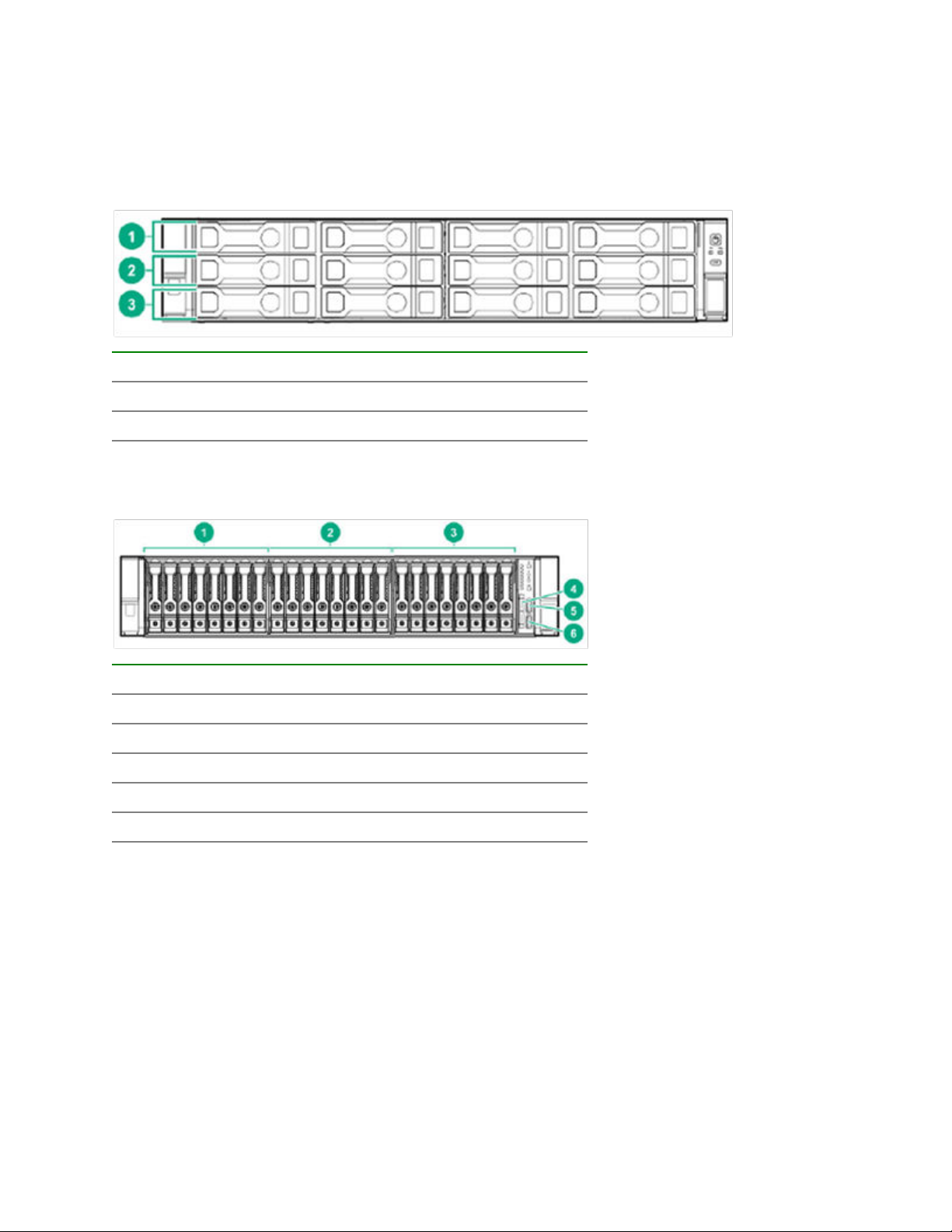
SFF front panel components
Item Description
1 Box 1 (Drives 1 - 4)
2 Box 2 (Drives 5 - 8)
3 Box 3 (Drives 9 - 12)
12-drive LFF front panel components
Item Description
1 Box 1 (Drives 1 - 8)
2 Box 2 (Drives 9 - 16)
3 Box 3 (Drives 17 - 24)
4 Serial Label Pull tab
5 iLO service port
6 USB 3.0 port
8 Component identification
Front panel LEDs and buttons
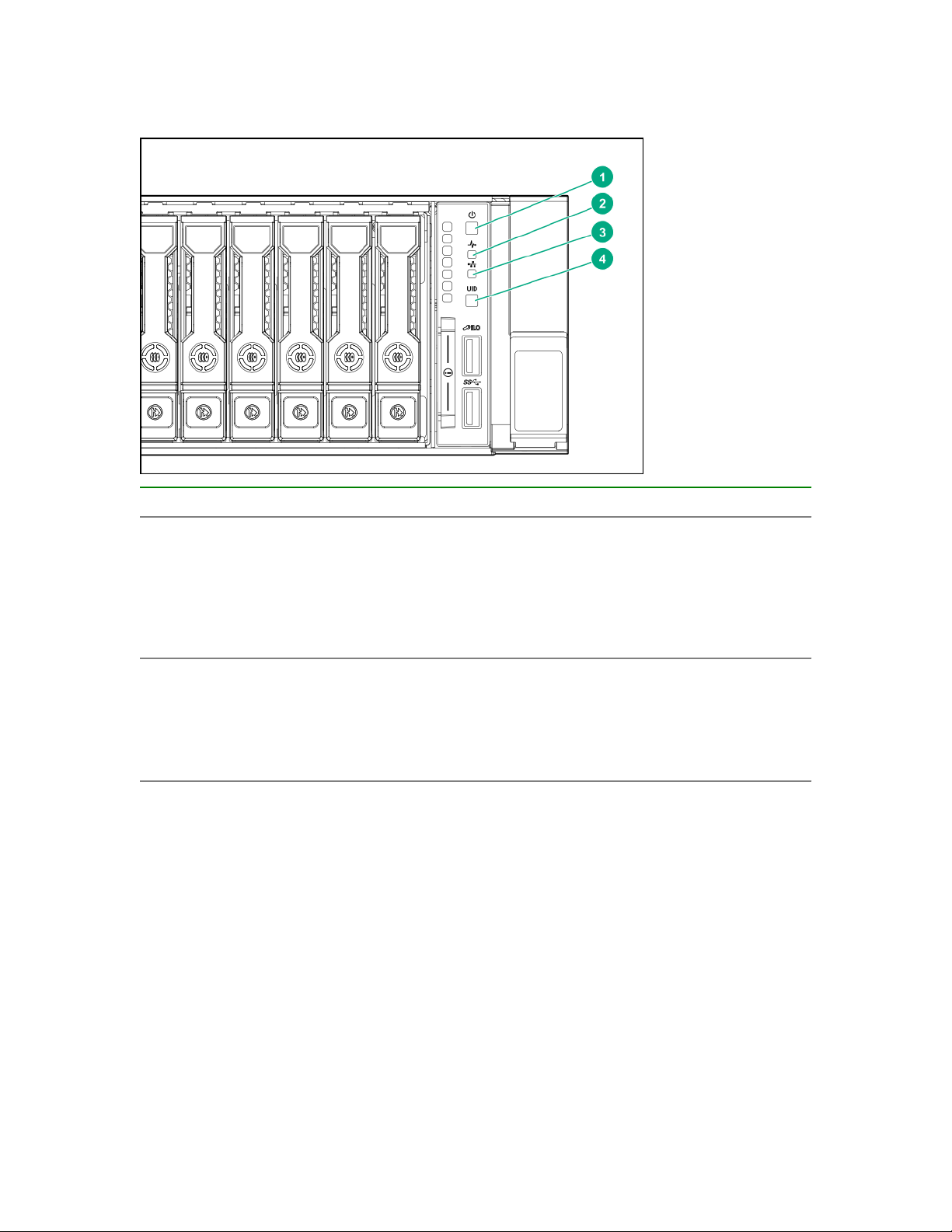
SFF front panel LEDs and button
Item Description Status
1 Power On/Standby button and
system power LED*
2 Health LED*
Solid green = System on
Flashing green (1 Hz/cycle per sec) = Performing
power on sequence
Solid amber = System in standby
Off = No power present†
Solid green = Normal
Flashing green (1 Hz/cycle per sec) = iLO is rebooting
Flashing amber = System degraded
Flashing red (1 Hz/cycle per sec) = System critical**
Table Continued
Front panel LEDs and buttons 9
Item Description Status
3 NIC status LED*
4 UID button/LED*
*When all four LEDs described in this table flash simultaneously, a power fault has occurred. For more
information, see "Power fault LEDs."
**If the health LED indicates a degraded or critical state, review the system IML or use iLO to review the
system health status.
Solid green = Link to network
Flashing green (1 Hz/cycle per sec) = Network active
Off = No network activity
Solid blue = Activated
Flashing blue:
• 1 Hz/cycle per sec = Remote management or
firmware upgrade in progress
• 4 Hz/cycle per sec = iLO manual reboot sequence
initiated
• 8 Hz/cycle per sec = iLO manual reboot sequence
in progress
Off = Deactivated
†Facility power is not present, power cord is not attached, no power supplies are installed, power supply
failure has occurred, or the power button cable is disconnected.
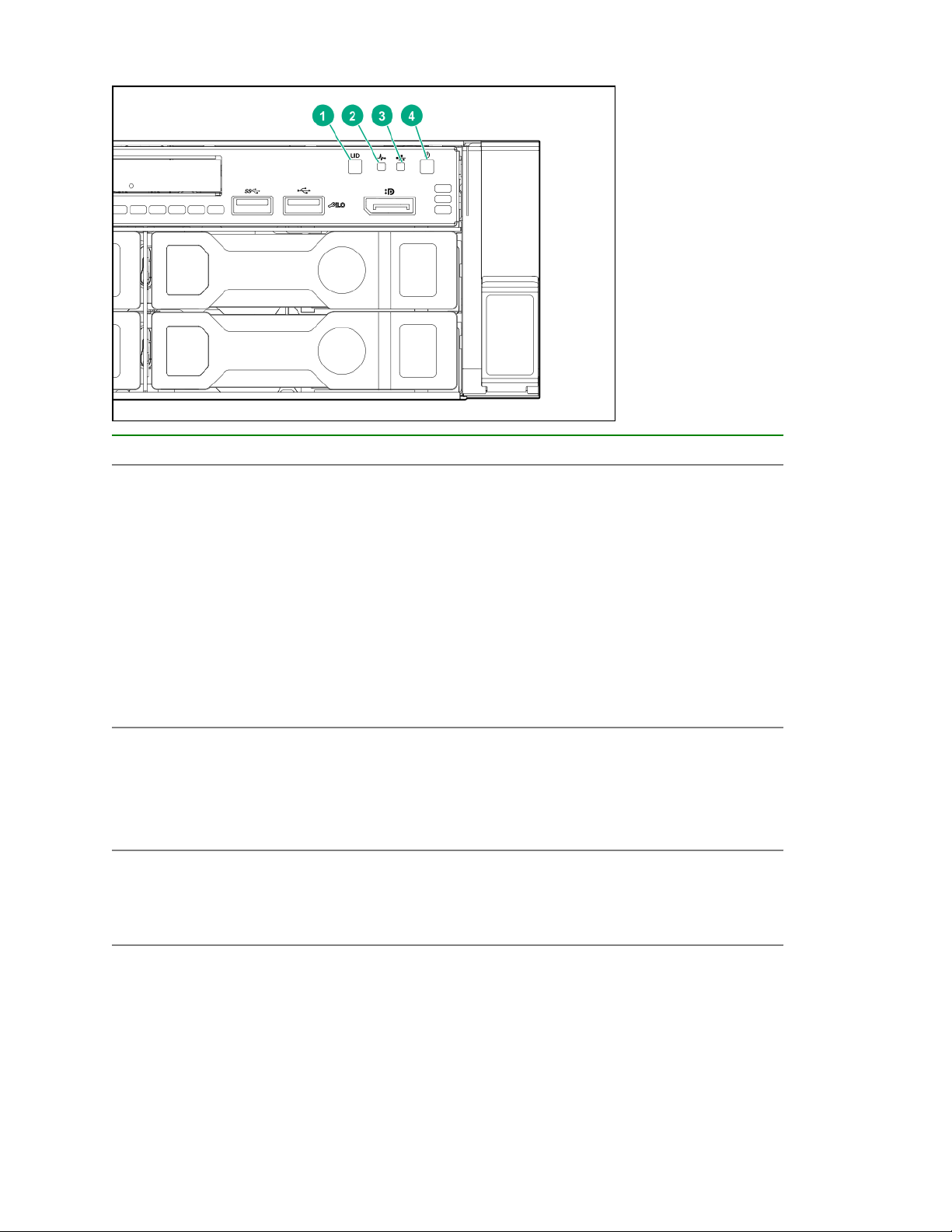
LFF 12-drive model front panel LEDs and button
10 Component identification

Item Description Status
1 Health LED*
2 Power On/Standby button and
system power LED*
3 NIC status LED*
4 UID button/LED*
Solid green = Normal
Flashing green (1 Hz/cycle per sec) = iLO is rebooting
Flashing amber = System degraded
Flashing red (1 Hz/cycle per sec) = System critical**
Solid green = System on
Flashing green (1 Hz/cycle per sec) = Performing
power on sequence
Solid amber = System in standby
Off = No power present†
Solid green = Link to network
Flashing green (1 Hz/cycle per sec) = Network active
Off = No network activity
Solid blue = Activated
Flashing blue:
• 1 Hz/cycle per sec = Remote management or
firmware upgrade in progress
• 4 Hz/cycle per sec = iLO manual reboot sequence
initiated
• 8 Hz/cycle per sec = iLO manual reboot sequence
in progress
Off = Deactivated
*When all four LEDs described in this table flash simultaneously, a power fault has occurred. For more
information, see "Power fault LEDs."
**If the health LED indicates a degraded or critical state, review the system IML or use iLO to review the
system health status.
†Facility power is not present, power cord is not attached, no power supplies are installed, power supply
failure has occurred, or the power button cable is disconnected.
Component identification 11
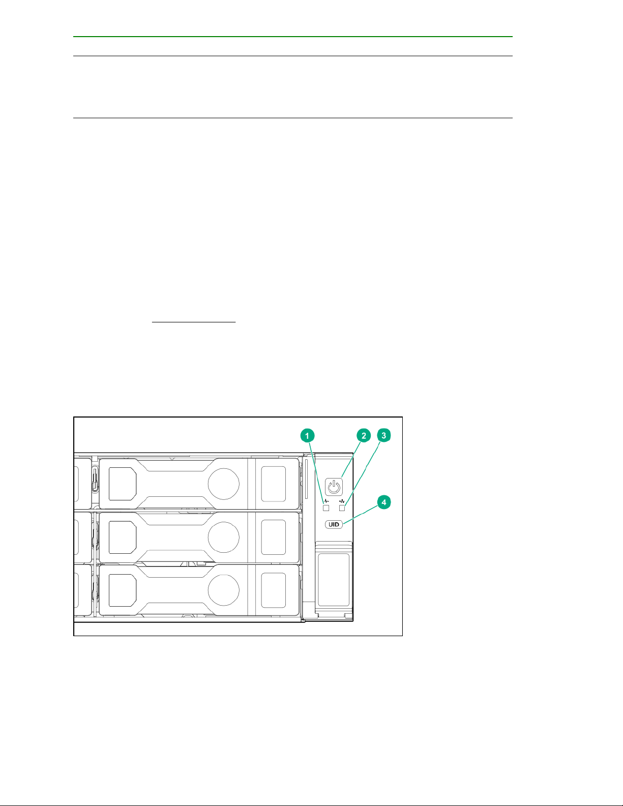
LFF power switch module LEDs and button
Item Description Status
1 UID button/LED*
2 Health LED*
3 NIC status LED*
Solid blue = Activated
Flashing blue:
• 1 Hz/cycle per sec = Remote management or
firmware upgrade in progress
• 4 Hz/cycle per sec = iLO manual reboot sequence
initiated
• 8 Hz/cycle per sec = iLO manual reboot sequence
in progress
Off = Deactivated
Solid green = Normal
Flashing green (1 Hz/cycle per sec) = iLO is rebooting
Flashing amber = System degraded
Flashing red (1 Hz/cycle per sec) = System critical**
Solid green = Link to network
Flashing green (1 Hz/cycle per sec) = Network active
Off = No network activity
4 Power On/Standby button and
system power LED*
12 Component identification
Solid green = System on
Flashing green (1 Hz/cycle per sec) = Performing
power on sequence
Solid amber = System in standby
Off = No power present†
*When all four LEDs described in this table flash simultaneously, a power fault has occurred. For more
information, see "Power fault LEDs."
**If the health LED indicates a degraded or critical state, review the system IML or use iLO to review the
system health status.
†Facility power is not present, power cord is not attached, no power supplies are installed, power supply
failure has occurred, or the power button cable is disconnected.
UID button functionality
The UID button can be used to display the Server Health Summary when the server will not power on. For
more information, see the latest HPE iLO User Guide on the Hewlett Packard Enterprise website.
Front panel LED power fault codes
The following table provides a list of power fault codes, and the subsystems that are affected. Not all power
faults are used by all servers.
Subsystem LED behavior
System board 1 flash
Processor 2 flashes
Memory 3 flashes
Riser board PCIe slots 4 flashes
FlexibleLOM 5 flashes
Removable HPE Smart Array SR Gen10 controller 6 flashes
System board PCIe slots 7 flashes
Power backplane or storage backplane 8 flashes
Power supply 9 flashes
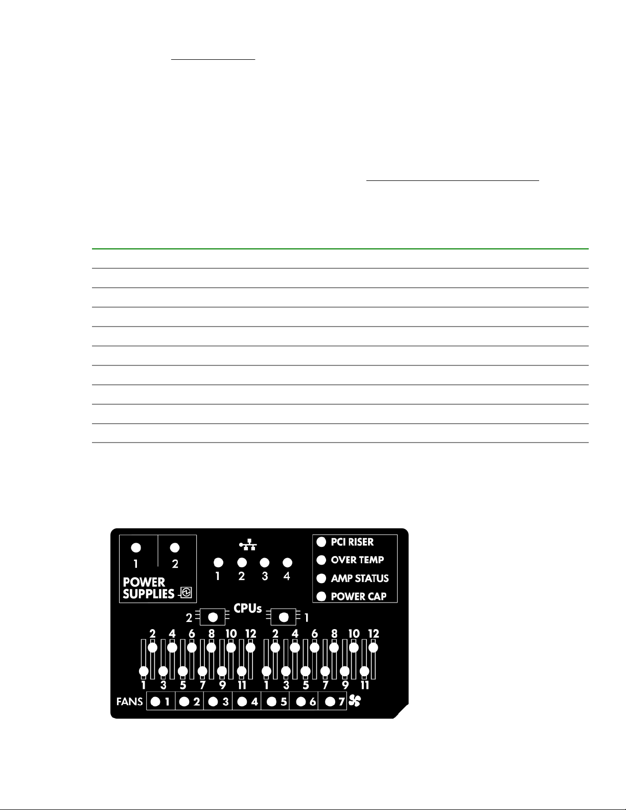
Systems Insight Display LEDs
The Systems Insight Display LEDs represent the system board layout. The display enables diagnosis with the
access panel installed.
UID button functionality 13

Description Status
Processor LEDs
DIMM LEDs
Fan LEDs
NIC LEDs
Power supply LEDs
PCI riser LED
Off = Normal
Amber = Failed processor
Off = Normal
Amber = Failed DIMM or configuration issue
Off = Normal
Amber = Failed fan or missing fan
Off = No link to network
Solid green = Network link
Flashing green = Network link with activity
If power is off, the front panel LED is not active. For
status, see Rear panel LEDs on page 17.
Off = Normal
Solid amber = Power subsystem degraded, power
supply failure, or input power lost.
Off = Normal
Amber = Incorrectly installed PCI riser cage
Over temp LED
Amp Status LED
Power cap LED
When the health LED on the front panel illuminates either amber or red, the server is experiencing a health
event. For more information on the combination of these LEDs, see Systems Insight Display combined
LED descriptions on page 14).
Off = Normal
Amber = High system temperature detected
Off = AMP modes disabled
Solid green = AMP mode enabled
Solid amber = Failover
Flashing amber = Invalid configuration
Off = System is in standby, or no cap is set.
Solid green = Power cap applied
Systems Insight Display combined LED descriptions
The combined illumination of the following LEDs indicates a system condition:
• Systems Insight Display LEDs
• System power LED
• Health LED
14 Systems Insight Display combined LED descriptions

Systems Insight Display
LED and color
Health
LED
System
power LED
Status
Processor (amber) Red Amber
Processor (amber) Amber Green Processor in socket X is in a pre-
DIMM (amber) Red Green One or more DIMMs have failed.
DIMM (amber) Amber Green DIMM in slot X is in a pre-failure
Over temp (amber) Amber Green The Health Driver has detected a
Over temp (amber) Red Amber The server has detected a hardware
One or more of the following
conditions may exist:
• Processor in socket X has failed.
• Processor X is not installed in the
socket.
• Processor X is unsupported.
• ROM detects a failed processor
during POST.
failure condition.
condition.
cautionary temperature level.
critical temperature level.
PCI riser (amber) Red Green The PCI riser cage is not seated
properly.
Fan (amber) Amber Green One fan has failed or has been
removed.
Fan (amber) Red Green Two or more fans have failed or been
removed.
Power supply (amber) Red Amber
One or more of the following
conditions may exist:
• Only one power supply is installed
and that power supply is in
standby.
• Power supply fault
• System board fault
Table Continued
Component identification 15
Systems Insight Display
LED and color
Health
LED
System
power LED
Status
Power supply (amber) Amber Green
Power cap (off) — Amber Standby
Power cap (green) — Flashing
green
Power cap (green) — Green Power is available.
Power cap (flashing amber) — Amber Power is not available.
IMPORTANT: If more than one DIMM slot LED is illuminated, further troubleshooting is required. Test
each bank of DIMMs by removing all other DIMMs. Isolate the failed DIMM by replacing each DIMM in a
bank with a known working DIMM.
One or more of the following
conditions may exist:
• Redundant power supply is
installed and only one power
supply is functional.
• AC power cord is not plugged into
redundant power supply.
• Redundant power supply fault
• Power supply mismatch at POST
or power supply mismatch through
hot-plug addition
Waiting for power
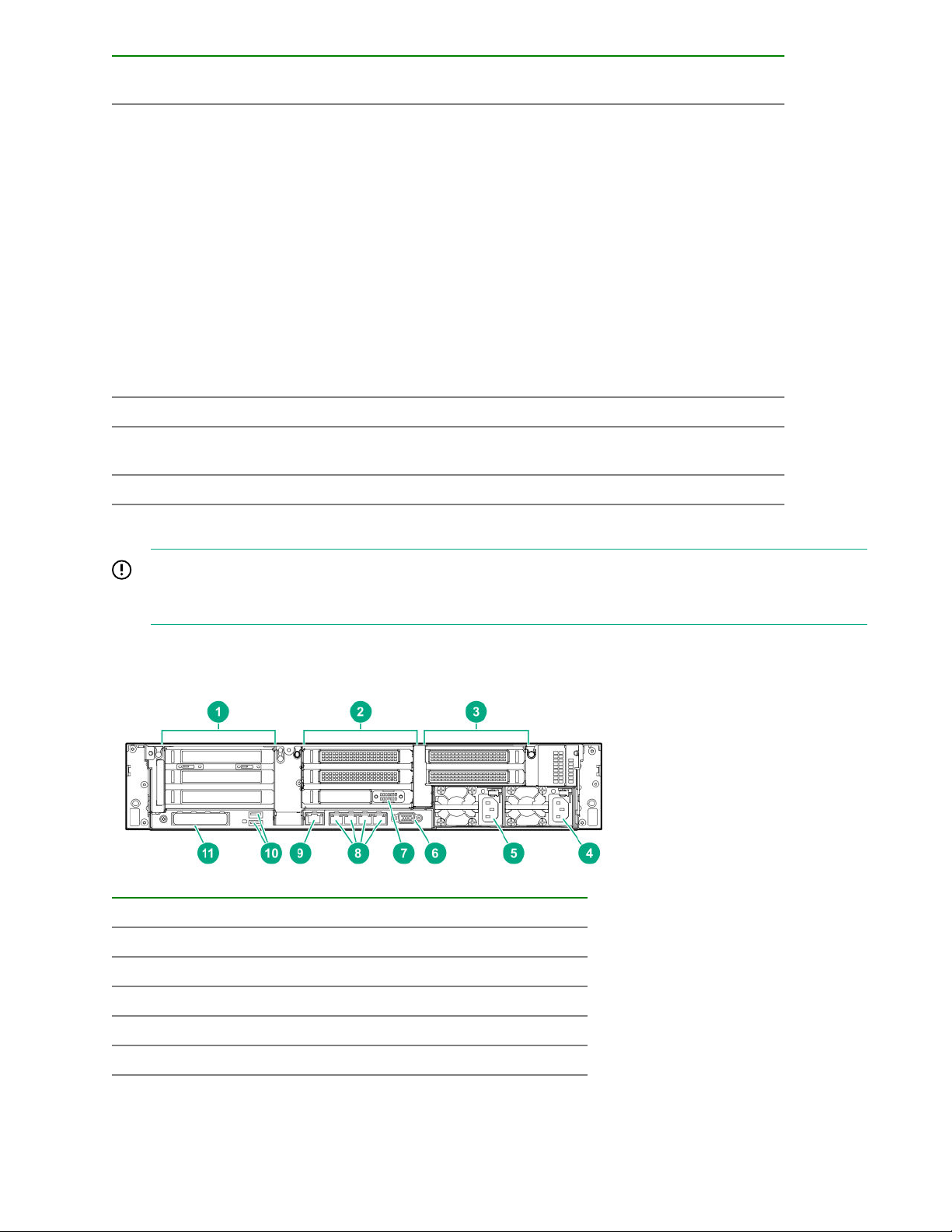
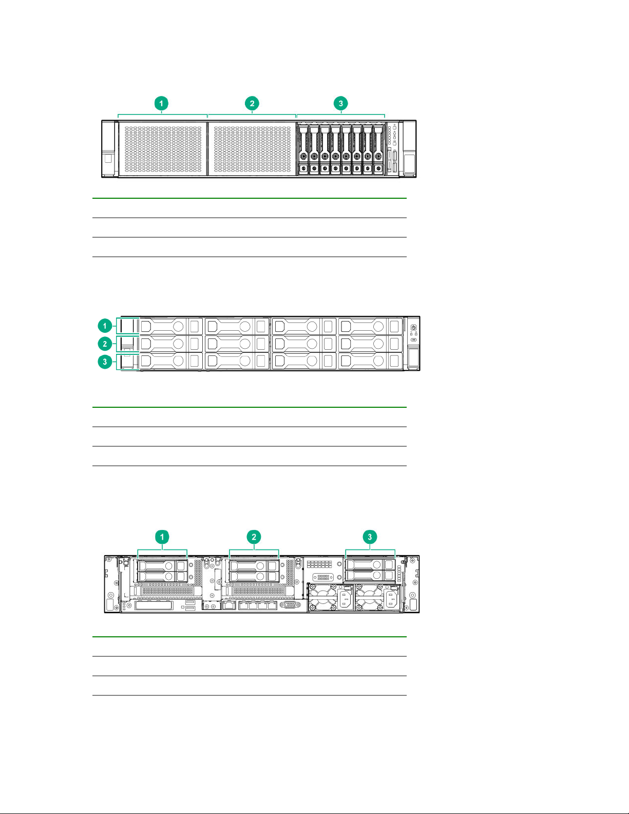
Rear panel components
Item Description
1 Primary riser slots 1-3 (Optional drive cage)
2 Optional riser slots 4-6 (Optional drive cage)
3 Optional riser slots 7-8 (Optional drive cage)
4 Power supply 1
5 Power supply 2
Table Continued
16 Rear panel components
Item Description
6 Video port
7 Serial port (optional)*
8 1Gb RJ-45 ports 1–4
9 iLO management port
10 USB 3.0 ports
11 FlexibleLOM slot
*When a tertiary riser cage is installed as shown, the serial port can installed in riser slot 6.
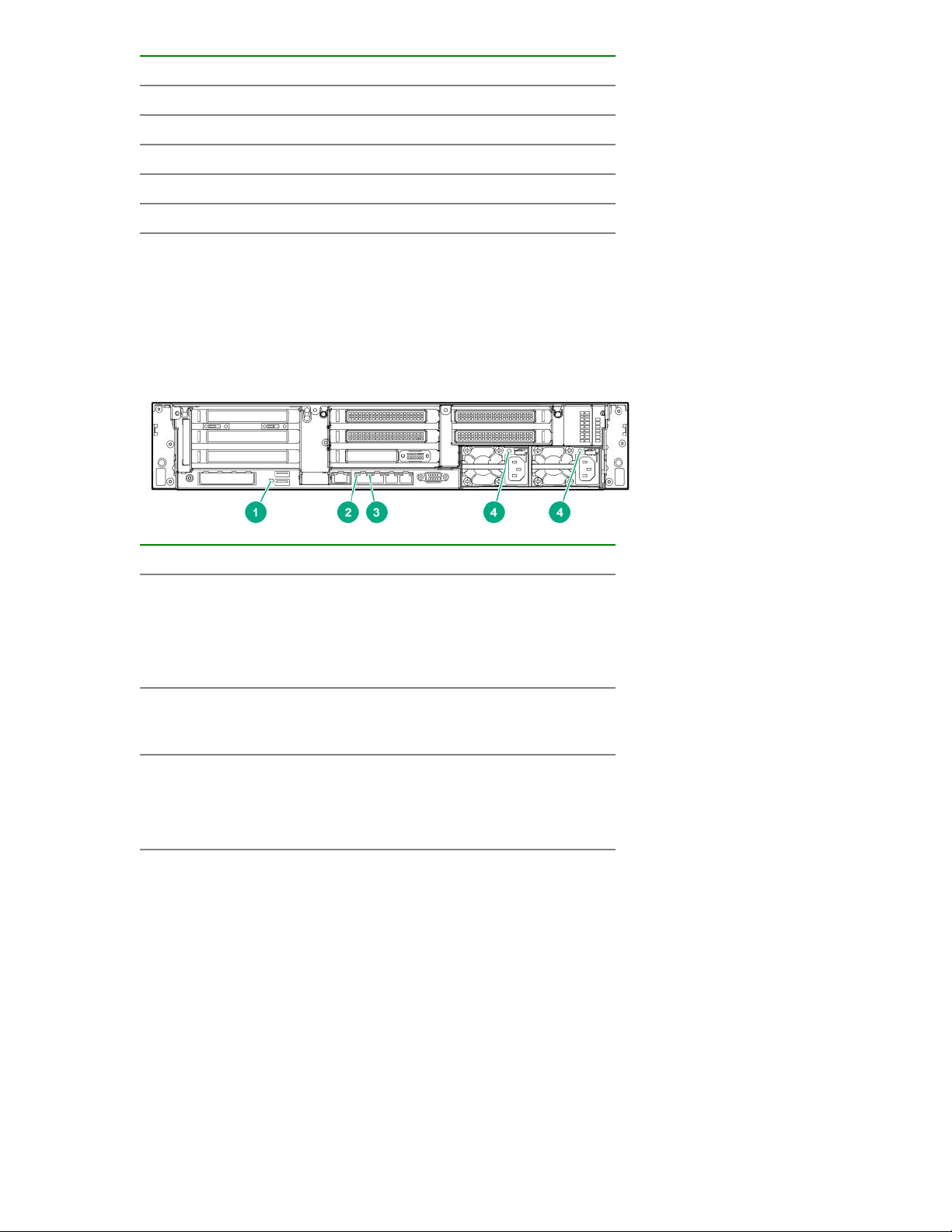
Rear panel LEDs
Item Description Status
1 UID LED
2 Link LED
3 Activity LED
4 Power supply
LEDs
Off = Deactivated
Solid blue = Activated
Flashing blue = System being
managed remotely
Off = No network link
Green = Network link
Off = No network activity
Solid green = Link to network
Flashing green = Network activity
Off = System is off or power supply has
failed.
Solid green = Normal
Rear panel LEDs 17
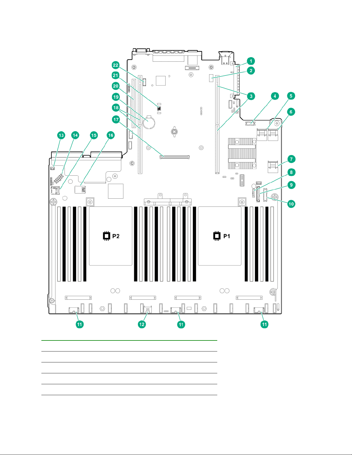
System board components
Item Description
1 FlexibleLOM connector
2 System maintenance switch
3 Primary PCIe riser connector
4 Front display port/USB 2.0 connector
18 System board components
Table Continued

Item Description
5 x4 SATA port 1
6 x4 SATA port 2
7 x2 SATA port 3
8 x1 SATA port 4
9 Optical disk drive/SATA port 5
10 Front power/USB 3.0 connector
11 Drive backplane power connectors
12 Smart Storage Battery connector
13 Chassis intrusion detection connector
14 Drive backplane power connector
15 Micro SD card slot
16 Dual internal USB 3.0 ports
17 Type-a Smart Array connector
18 Secondary PCIe riser connector*
19 System battery
20 Tertiary PCIe riser connector*
21 TPM connector
22 Serial port connector (optional)
* Requires a second processor
System maintenance switch descriptions
Position Default Function
1
S1
S2 — Reserved
S3 Off Reserved
S4 Off Reserved
1
S5
Off
Off
Off = iLO security is enabled.
On = iLO security is disabled.
Off = Power-on password is
enabled.
On = Power-on password is
disabled.
S6
1, 2
Off
Off = No function
On = Restore default
manufacturing settings
Table Continued
System maintenance switch descriptions 19
Position Default Function
S7 — Reserved
S8 — Reserved
S9 — Reserved
S10 — Reserved
S11 — Reserved
S12 — Reserved
1
You can access the redundant ROM by setting S1, S5, and S6 to On.
2
When the system maintenance switch position 6 is set to the On position, the system is prepared to restore
all configuration settings to their manufacturing defaults.
When the system maintenance switch position 6 is set to the On position and Secure Boot is enabled, some
configurations cannot be restored. For more information, see Secure Boot configuration.
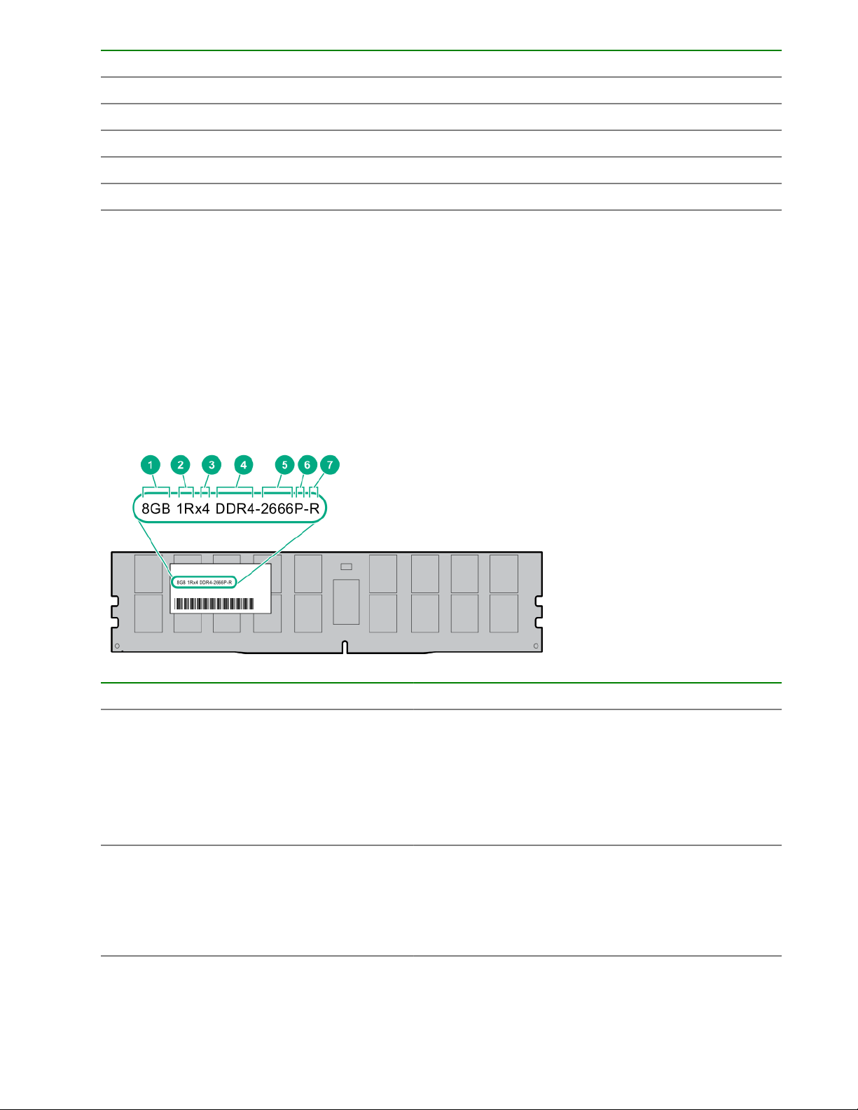
DIMM label identification
To determine DIMM characteristics, see the label attached to the DIMM. The information in this section helps
you to use the label to locate specific information about the DIMM.
Item Description Example
1 Capacity
2 Rank
20 DIMM label identification
8 GB
16 GB
32 GB
64 GB
128 GB
1R = Single rank
2R = Dual rank
4R = Quad rank
8R = Octal rank
Table Continued
Item Description Example
3 Data width on DRAM
4 Memory generation
5 Maximum memory speed
6 CAS latency
7 DIMM type
x4 = 4-bit
x8 = 8-bit
x16 = 16-bit
PC4 = DDR4
2133 MT/s
2400 MT/s
2666 MT/s
P = CAS 15-15-15
T = CAS 17-17-17
U = CAS 20-18-18
V = CAS 19-19-19 (for RDIMM, LRDIMM)
V = CAS 22-19-19 (for 3DS TSV LRDIMM)
R = RDIMM (registered)
L = LRDIMM (load reduced)
E = Unbuffered ECC (UDIMM)
For more information about product features, specifications, options, configurations, and compatibility, see the
product QuickSpecs on the Hewlett Packard Enterprise website (http://www.hpe.com/info/qs).
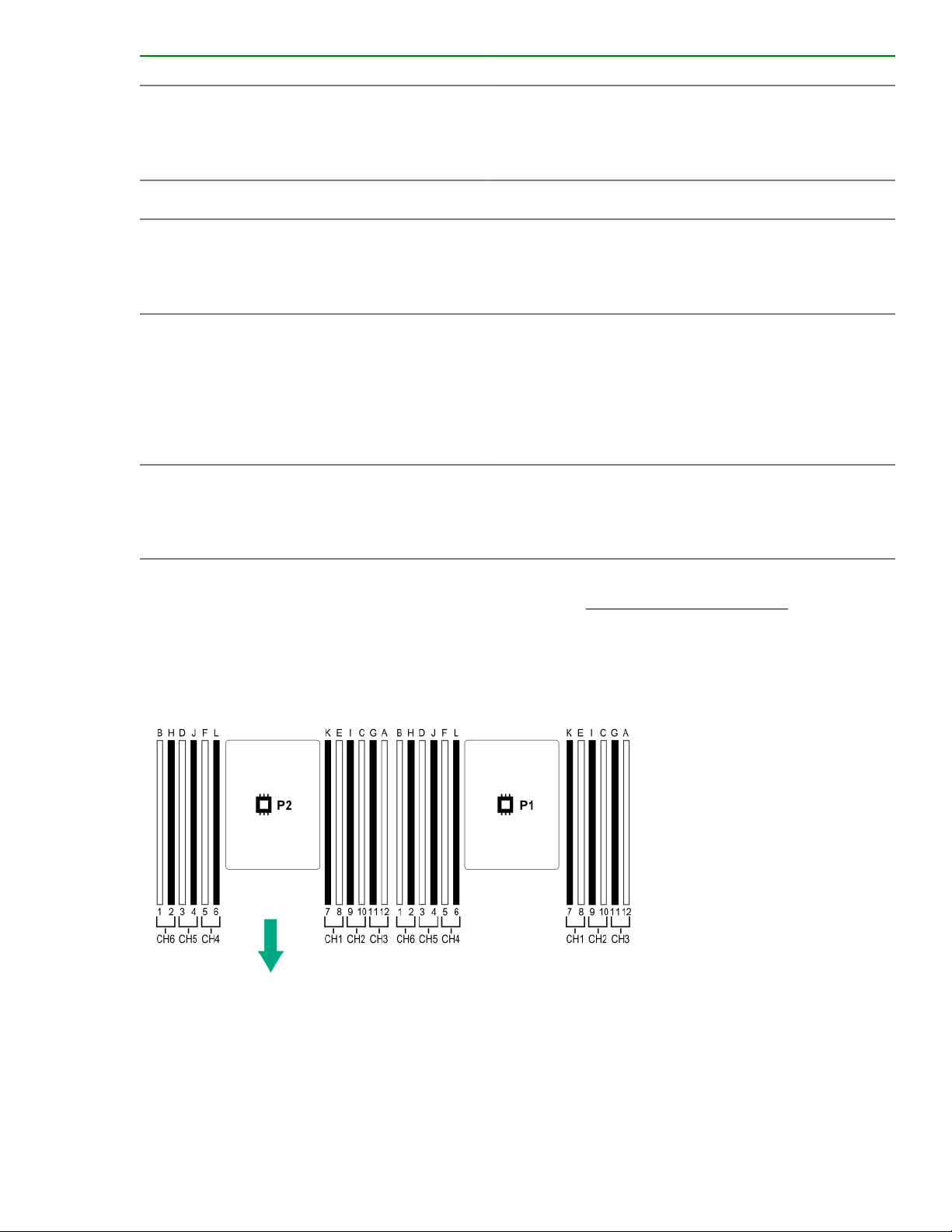
DIMM slot locations
DIMM slots are numbered sequentially (1 through 12) for each processor. The supported AMP modes use the
letter assignments for population guidelines.
NVDIMM identification
NVDIMM boards are blue instead of green. This change to the color makes it easier to distinguish NVDIMMs
from DIMMs.
To determine NVDIMM characteristics, see the full product description as shown in the following example:
DIMM slot locations 21
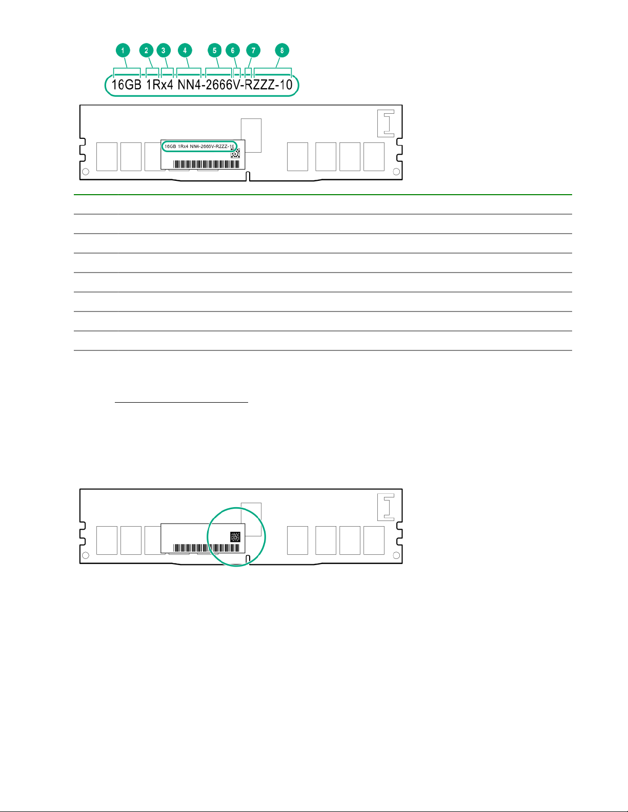
Item Description Definition
1 Capacity 16 GiB
2 Rank 1R (Single rank)
3 Data width per DRAM chip x4 (4 bit)
4 Memory type NN4=DDR4 NVDIMM-N
5 Maximum memory speed 2667 MT/s
6 Speed grade V (latency 19-19-19)
7 DIMM type RDIMM (registered)
8 Other —
For more information about NVDIMMs, see the product QuickSpecs on the Hewlett Packard Enterprise
website (http://www.hpe.com/info/qs).
NVDIMM 2D Data Matrix barcode
The 2D Data Matrix barcode is on the right side of the NVDIMM label and can be scanned by a cell phone or
other device.
When scanned, the following information from the label can be copied to your cell phone or device:
• (P) is the module part number.
• (L) is the technical details shown on the label.
• (S) is the module serial number.
Example: (P)HMN82GR7AFR4N-VK (L)16GB 1Rx4 NN4-2666V-RZZZ-10(S)80AD-01-1742-11AED5C2
22 NVDIMM 2D Data Matrix barcode
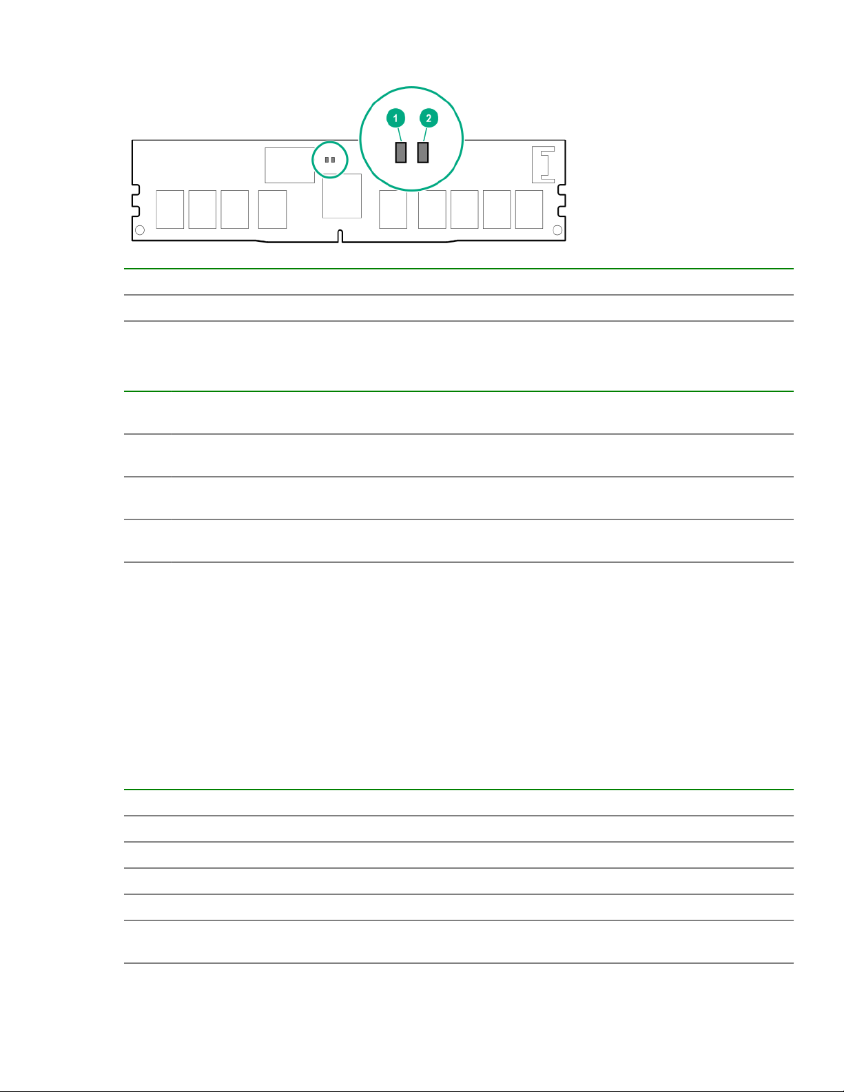
NVDIMM LED identification
Item LED description LED color
1 Power LED Green
2 Function LED Blue
NVDIMM-N LED combinations
State Definition NVDIMM-N Power LED
0 AC power is on (12 V rail) but the NVM
controller is not working or not ready.
1 AC power is on (12 V rail) and the NVM
controller is ready.
2 AC power is off or the battery is off (12 V
rail off).
3 AC power is on (12 V rail) or the battery is
on (12 V rail) and the NVDIMM-N is active
(backup and restore).
NVDIMM Function LED patterns
For the purpose of this table, the NVDIMM-N LED operates as follows:
• Solid indicates that the LED remains in the on state.
• Flashing indicates that the LED is on for 2 seconds and off for 1 second.
• Fast-flashing indicates that the LED is on for 300 ms and off for 300 ms.
State Definition NVDIMM-N Function LED
NVDIMM-N Function LED
(green)
On Off
On On
Off Off
On Flashing
(blue)
0 The restore operation is in progress. Flashing
1 The restore operation is successful. Solid or On
2 Erase is in progress. Flashing
3 The erase operation is successful. Solid or On
4 The NVDIMM-N is armed, and the NVDIMM-N is in
normal operation.
Solid or On
NVDIMM LED identification 23
Table Continued
State Definition NVDIMM-N Function LED
5 The save operation is in progress. Flashing
6 The NVDIMM-N finished saving and battery is still turned
on (12 V still powered).
7 The NVDIMM-N has an internal error or a firmware
update is in progress. For more information about an
NVDIMM-N internal error, see the IML.
Solid or On
Fast-flashing
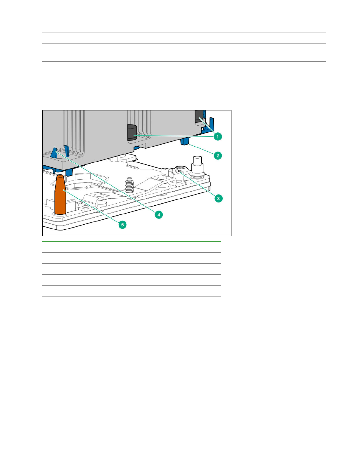
Processor, heatsink, and socket components
Item Description
1 Heatsink nuts
2 Processor carrier
3 Pin 1 indicator
4 Heatsink latch
5 Alignment post
1
Symbol also on the processor and frame.
Drives
1
24 Processor, heatsink, and socket components
SAS/SATA drive components and LEDs
Item Description Status
1 Locate
• Solid blue = The drive is being identified by a host
application.
• Flashing blue = The drive carrier firmware is being
updated or requires an update.
2 Activity ring LED
• Rotating green = Drive activity.
3 Do not remove LED
4 Drive status LED
• Off = No drive activity.
• Solid white = Do not remove the drive. Removing
the drive causes one or more of the logical drives to
fail.
• Off = Removing the drive does not cause a logical
drive to fail.
• Solid green = The drive is a member of one or more
logical drives.
• Flashing green = The drive is rebuilding or
performing a RAID migration, strip size migration,
capacity expansion, or logical drive extension, or is
erasing.
• Flashing amber/green = The drive is a member of
one or more logical drives and predicts the drive will
fail.
• Flashing amber = The drive is not configured and
predicts the drive will fail.
• Solid amber = The drive has failed.
• Off = The drive is not configured by a RAID
controller.
SAS/SATA drive components and LEDs 25
NVMe SSD LED definitions
The NVMe SSD is a PCIe bus device. A device attached to a PCIe bus cannot be removed without allowing
the device and bus to complete and cease the signal/traffic flow.
CAUTION: Do not remove an NVMe SSD from the drive bay while the Do not remove LED is flashing.
The Do not remove LED flashes to indicate that the device is still in use. Removing the NVMe SSD
before the device has completed and ceased signal/traffic flow can cause loss of data.
Item LED Status Definition
1 Locate Solid blue The drive is being identified by a host application.
Flashing blue The drive carrier firmware is being updated or requires an update.
2 Activity
ring
Off No drive activity
3 Drive
status
Flashing green The drive is doing one of the following:
Flashing amber/
Flashing amber The drive is not configured and predicts the drive will fail.
Solid amber The drive has failed.
Rotating green Drive activity
Solid green The drive is a member of one or more logical drives.
• Rebuilding
• Performing a RAID migration
• Performing a stripe size migration
• Performing a capacity expansion
• Performing a logical drive extension
• Erasing
The drive is a member of one or more logical drives and predicts the
green
drive will fail.
Off The drive is not configured by a RAID controller.
4 Do not
remove
26 NVMe SSD LED definitions
Solid white Do not remove the drive. The drive must be ejected from the PCIe bus
prior to removal.
Table Continued
Item LED Status Definition
Flashing white The drive ejection request is pending.
Off The drive has been ejected.
5 Power Solid green Do not remove the drive. The drive must be ejected from the PCIe bus
prior to removal.
Flashing green The drive ejection request is pending.
Off The drive has been ejected.
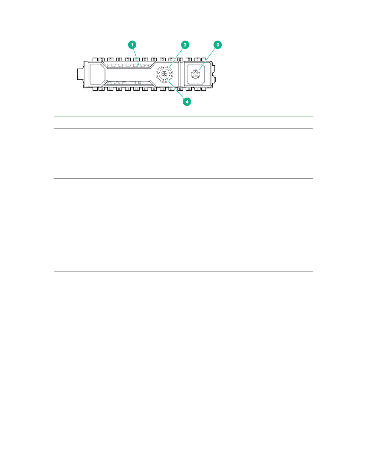
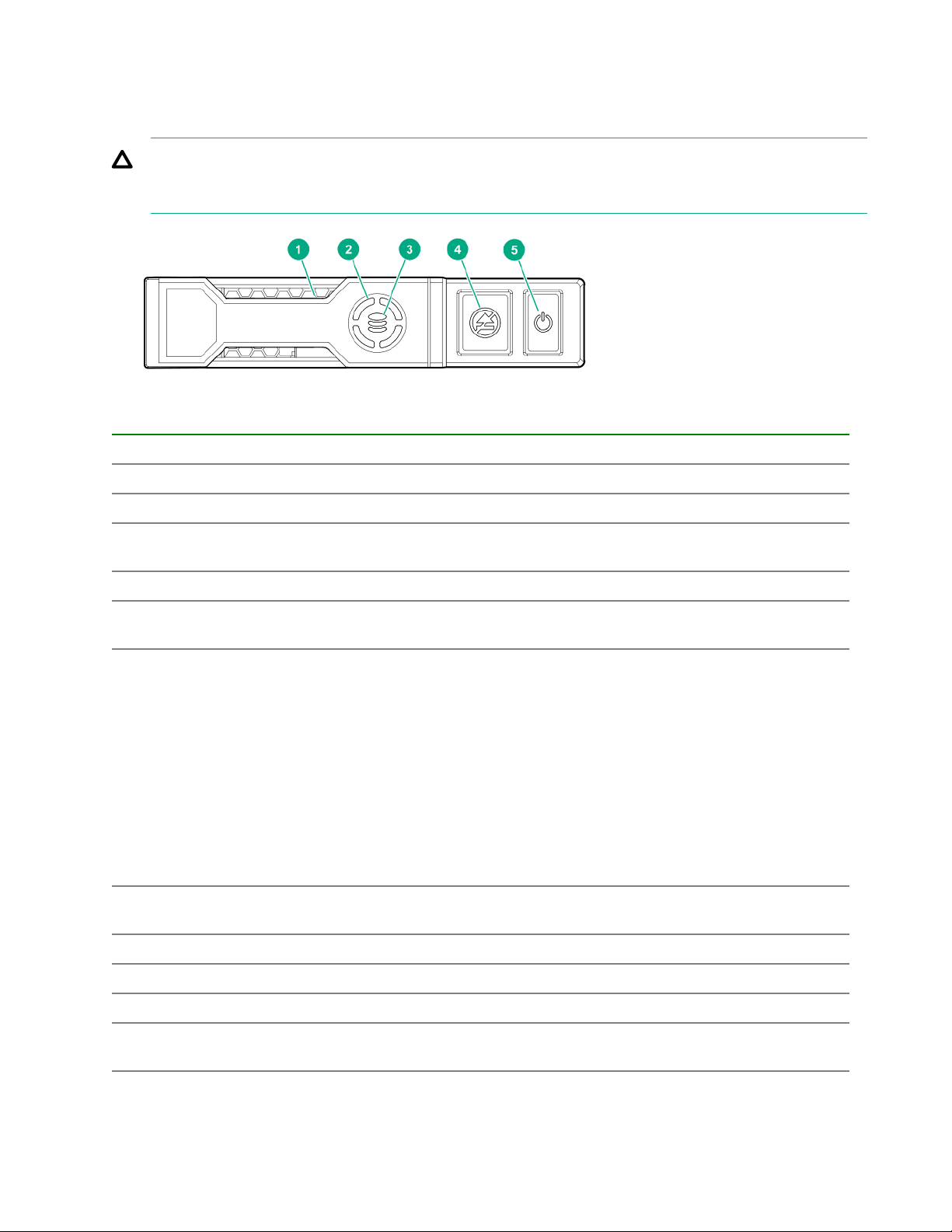
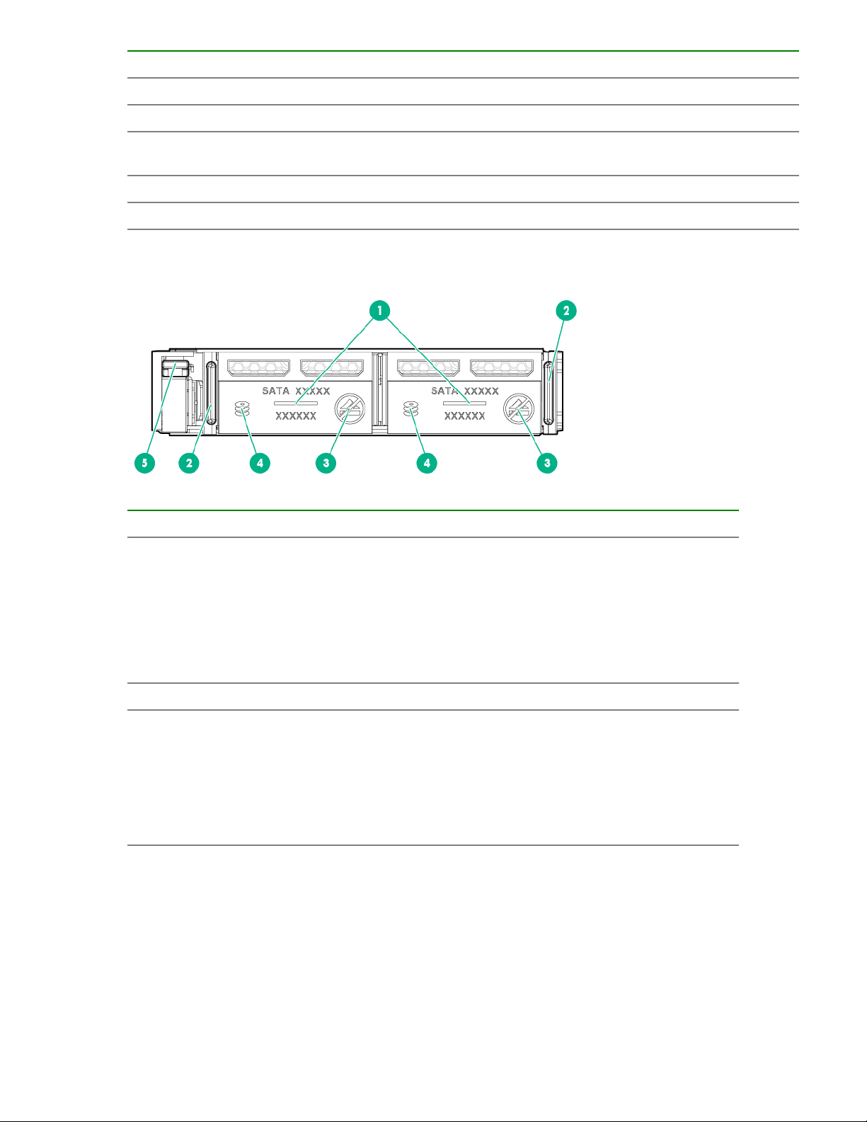
uFF drive components and LEDs
Item Description Status
1 Locate
• Off—Normal
• Solid blue—The drive is being identified by a host
application
• Flashing blue—The drive firmware is being updated
or requires an update
2 uFF drive ejection latch Removes the uFF drive when released
3 Do not remove LED
• Off—OK to remove the drive. Removing the drive
does not cause a logical drive to fail.
• Solid white—Do not remove the drive. Removing
the drive causes one or more of the logical drives to
fail.
Table Continued
uFF drive components and LEDs 27
Item Description Status
4 Drive status LED
• Off—The drive is not configured by a RAID
controller
• Solid green—The drive is a member of one or more
logical drives
• Flashing green (4 Hz)—The drive is operating
normally and has activity
• Flashing green (1 Hz)—The drive is rebuilding or
performing a RAID migration, stripe size migration,
capacity expansion, logical drive extension, or is
erasing
• Flashing amber/green (1 Hz)—The drive is a
member of one or more logical drives that predicts
the drive will fail
• Solid amber—The drive has failed
• Flashing amber (1 Hz)—The drive is not configured
and predicts the drive will fail
5 Adapter ejection release latch
and handle
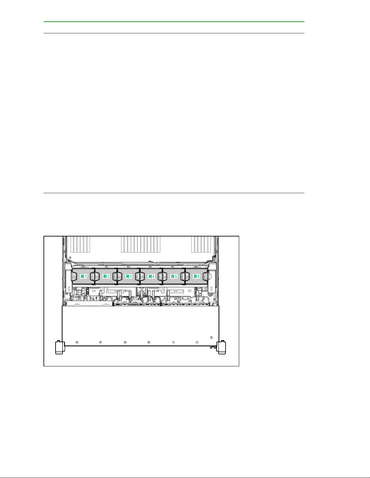
Fan bay numbering
Removes the SFF flash adapter when released
28 Fan bay numbering
Drive box identification
Front boxes
Item Description
1 Box 1
2 Box 2
3 Box 3
Item Description
1 Box 1
2 Box 2
3 Box 3
Rear boxes
Item Description
1 Box 4
2 Box 5
3 Box 6
Drive box identification 29

Item Description
1 Box 4
2 Box 6
Midplane box (LFF only)
Item Description
1 Box 7
Drive bay numbering
Drive bay numbering depends on how the drive backplanes are connected:
• To a controller
◦ Embedded controllers use the onboard SATA ports.
◦ Type-a controllers install to the type-a smart array connector.
◦ Type-p controllers install to a PCIe riser.
• To a SAS expander
Installs in the primary or secondary PCIe riser
30 Drive bay numbering
 Loading...