


HPE ProLiant BL460c Gen10 Server Blade User Guide
Abstract
This document is for the person who installs, administers, and troubleshoots server blades.
Hewlett Packard Enterprise assumes you are qualified in the servicing of computer equipment
and trained in recognizing hazards in products with hazardous energy levels.
Part Number: 876833-006
Published: May 2019
Edition: 6

©
Copyright 2017-2019 Hewlett Packard Enterprise Development LP
Notices
The information contained herein is subject to change without notice. The only warranties for Hewlett
Packard Enterprise products and services are set forth in the express warranty statements accompanying
such products and services. Nothing herein should be construed as constituting an additional warranty.
Hewlett Packard Enterprise shall not be liable for technical or editorial errors or omissions contained
herein.
Confidential computer software. Valid license from Hewlett Packard Enterprise required for possession,
use, or copying. Consistent with FAR 12.211 and 12.212, Commercial Computer Software, Computer
Software Documentation, and Technical Data for Commercial Items are licensed to the U.S. Government
under vendor's standard commercial license.
Links to third-party websites take you outside the Hewlett Packard Enterprise website. Hewlett Packard
Enterprise has no control over and is not responsible for information outside the Hewlett Packard
Enterprise website.
Acknowledgments
Microsoft® and Windows® are either registered trademarks or trademarks of Microsoft Corporation in the
United States and/or other countries.
Linux® is the registered trademark of Linus Torvalds in the U.S. and other countries.
microSD is a trademark or a registered trademark of SD-3C in the United States, other countries or both.
Red Hat® is a registered trademark of Red Hat, Inc. in the United States and other countries.
VMware® is a registered trademark or a trademark of VMware, Inc. in the United States and/or other
jurisdictions.

Contents
Component identification.......................................................................6
Front panel components............................................................................................................... 6
Front panel LEDs and buttons...................................................................................................... 7
Front panel LED power fault codes....................................................................................8
Serial label pull tab information.......................................................................................... 8
Drive numbering............................................................................................................................9
Hot-plug drive LED definitions...................................................................................................... 9
NVMe SSD components............................................................................................................. 10
SFF flash adapter components and LED definitions...................................................................11
SUV cable connectors................................................................................................................ 12
System board components......................................................................................................... 13
System maintenance switch.............................................................................................14
DIMM slot locations..........................................................................................................15
DIMM label identification.................................................................................................. 15
NVDIMM identification......................................................................................................17
NVDIMM LED identification..............................................................................................18
Mezzanine connector definitions......................................................................................19
Mezzanine connector guide pin locations........................................................................ 19
Operations............................................................................................. 21
Power up the server blade.......................................................................................................... 21
Power down the server blade..................................................................................................... 21
Remove the server blade............................................................................................................22
Remove the access panel...........................................................................................................22
Install the access panel...............................................................................................................23
Remove the DIMM baffles...........................................................................................................23
Install the DIMM baffles...............................................................................................................25
Remove an M.2 SSD from the M.2 riser board...........................................................................26
Remove the M.2 interposer board and the M.2 riser board........................................................ 27
Relocate the PEM nut and rubber stopper..................................................................................28
Remove the direct connect SATA cable......................................................................................31
Install the direct connect SATA cable..........................................................................................31
Remove the mezzanine assembly.............................................................................................. 32
Install the mezzanine assembly.................................................................................................. 33
Remove the FlexibleLOM........................................................................................................... 33
Remove the storage controller or NVMe pass-through board.................................................... 34
Remove an NVMe SSD.............................................................................................................. 35
Remove a SAS or SATA drive.....................................................................................................35
Remove the front panel/drive cage assembly.............................................................................36
Install the front panel/drive cage assembly.................................................................................37
Setup...................................................................................................... 39
Overview..................................................................................................................................... 39
Server blade warnings and cautions...........................................................................................39
Installing an HPE BladeSystem c-Class enclosure.....................................................................39
Preparing the enclosure................................................................................................... 40
Installing server blade options.................................................................................................... 40
Installing interconnect modules...................................................................................................40
3

Interconnect bay numbering and device mapping........................................................... 40
Connecting to the network.......................................................................................................... 42
Install the server blade................................................................................................................42
Completing the configuration...................................................................................................... 44
Hardware options installation..............................................................45
Introduction................................................................................................................................. 45
Drive bay options........................................................................................................................ 45
Installing the SAS and SATA drive options.......................................................................45
Installing the NVMe SSD options..................................................................................... 46
Installing the SFF Flash Adapter option........................................................................... 47
HPE Smart Array P204i SR Gen10 Controller option................................................................. 48
HPE Smart Storage Battery........................................................................................................ 50
Installing the HPE Smart Storage Battery........................................................................ 51
Mezzanine card option................................................................................................................53
Installing the mezzanine card option................................................................................53
FlexibleLOM option..................................................................................................................... 55
Installing the FlexibleLOM................................................................................................55
M.2 enablement option............................................................................................................... 56
Installing the M.2 riser board and M.2 interposer board...................................................57
Installing the M.2 SSDs....................................................................................................59
Memory options...........................................................................................................................60
DIMM and NVDIMM population information.....................................................................60
DIMM-processor compatibility..........................................................................................60
HPE SmartMemory speed information.............................................................................60
Installing a DIMM..............................................................................................................60
HPE 16GB NVDIMM option............................................................................................. 62
Installing the processor-heatsink assembly................................................................................ 66
HPE Trusted Platform Module 2.0 Gen10 option........................................................................68
Overview.......................................................................................................................... 68
TPM 2.0 location.............................................................................................................. 69
HPE Trusted Platform Module 2.0 Guidelines..................................................................69
Installing and enabling the HPE TPM 2.0 Gen10 Kit....................................................... 70
Cabling................................................................................................... 75
Cabling resources....................................................................................................................... 75
HPE Smart Storage Battery cabling............................................................................................75
Direct connect SATA cabling.......................................................................................................75
Using the HPE c-Class Blade SUV Cable.................................................................................. 76
Disconnecting and replacing the SUV cable...............................................................................76
Connecting locally to a server blade with video and USB devices............................................. 76
Accessing a server blade with local KVM........................................................................ 77
Accessing local media devices........................................................................................ 77
Troubleshooting.................................................................................... 79
Troubleshooting resources..........................................................................................................79
Software and configuration utilities.................................................... 80
Server mode................................................................................................................................80
Product QuickSpecs................................................................................................................... 80
Active Health System Viewer......................................................................................................80
Active Health System....................................................................................................... 81
4

HPE iLO 5................................................................................................................................... 81
iLO Federation..................................................................................................................82
iLO Service Port............................................................................................................... 82
iLO RESTful API...............................................................................................................83
RESTful Interface Tool..................................................................................................... 83
iLO Amplifier Pack............................................................................................................83
Integrated Management Log.......................................................................................................83
Intelligent Provisioning................................................................................................................ 84
Intelligent Provisioning operation..................................................................................... 84
Management Security................................................................................................................. 85
Scripting Toolkit for Windows and Linux..................................................................................... 85
UEFI System Utilities.................................................................................................................. 86
Selecting the boot mode ................................................................................................. 86
Secure Boot......................................................................................................................87
Launching the Embedded UEFI Shell ............................................................................. 87
HPE Smart Storage Administrator.............................................................................................. 88
HPE InfoSight for servers .......................................................................................................... 88
USB support................................................................................................................................89
External USB functionality................................................................................................89
Redundant ROM support............................................................................................................ 89
Safety and security benefits............................................................................................. 89
Keeping the system current........................................................................................................ 89
Updating firmware or system ROM.................................................................................. 89
Drivers..............................................................................................................................92
Software and firmware..................................................................................................... 92
Operating system version support................................................................................... 92
HPE Pointnext Portfolio....................................................................................................93
Proactive notifications...................................................................................................... 93
Removing and replacing the system battery......................................94
Electrostatic discharge.........................................................................96
Preventing electrostatic discharge.............................................................................................. 96
Grounding methods to prevent electrostatic discharge...............................................................96
Specifications........................................................................................97
Environmental specifications ..................................................................................................... 97
Server blade specifications......................................................................................................... 97
Websites................................................................................................ 98
Support and other resources...............................................................99
Accessing Hewlett Packard Enterprise Support......................................................................... 99
Accessing updates......................................................................................................................99
Customer self repair..................................................................................................................100
Remote support........................................................................................................................ 100
Warranty information.................................................................................................................100
Regulatory information..............................................................................................................101
Documentation feedback.......................................................................................................... 101
5
Component identification
1
2
3
4
5
7
6
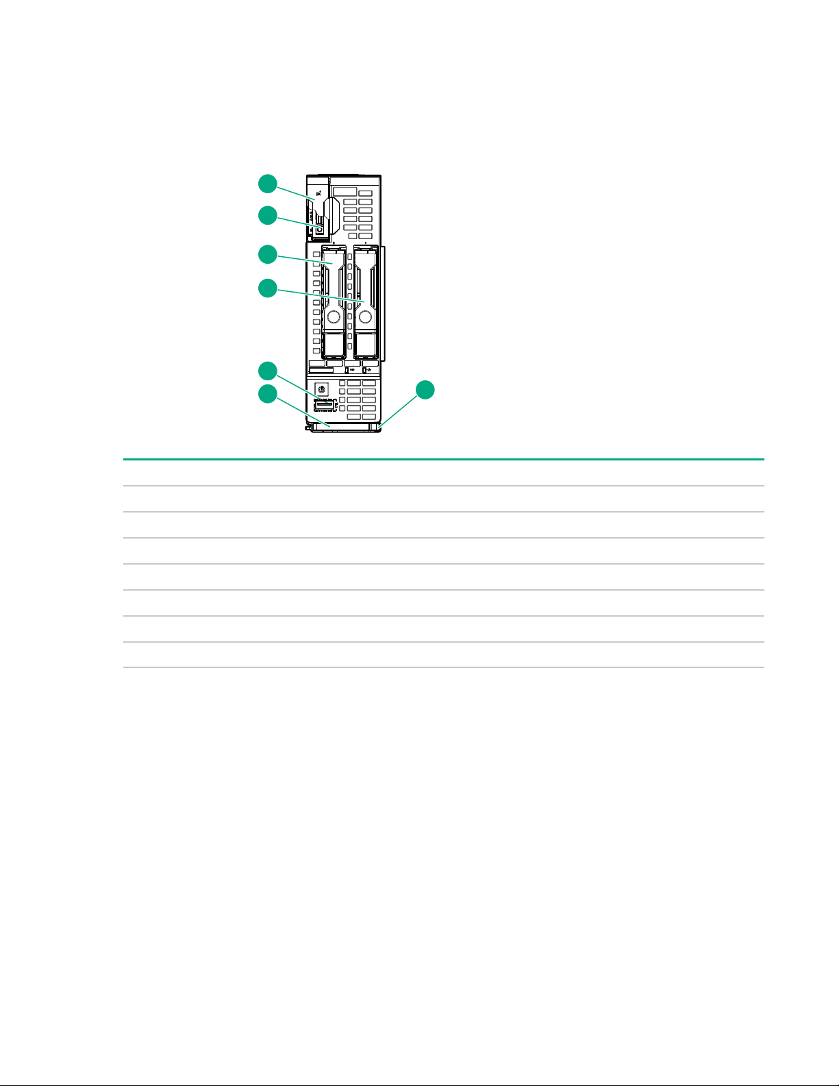
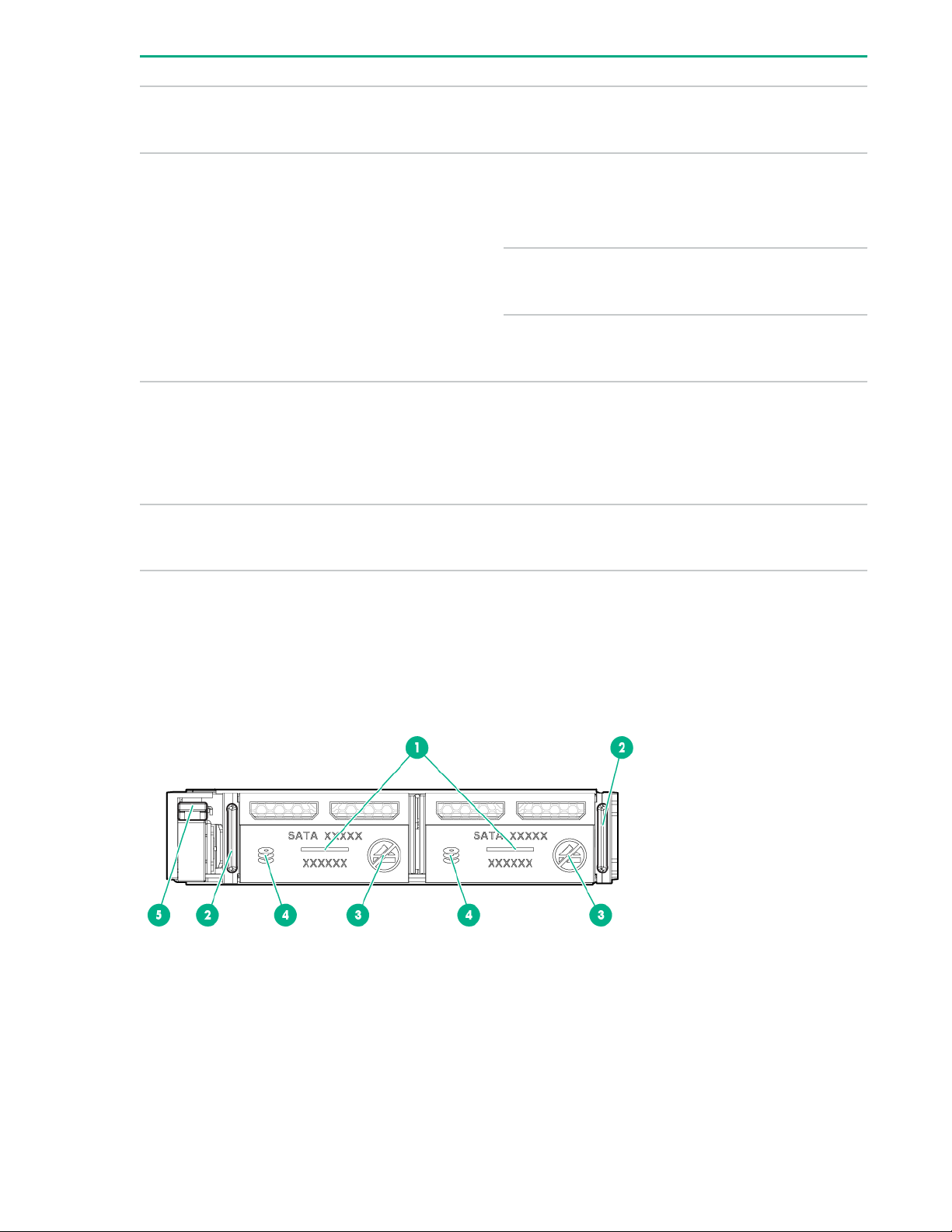
Front panel components
Item Description
1 Serial label pull tab
2 HPE c-Class Blade SUV connector1 (behind the serial label pull tab)
3 Drive bay 2
4 Drive bay 1
5 iLO Service port
6 Server blade release lever
7 Server blade release latch
1
The SUV connector and the c-Class Blade SUV Cable are used for some server blade configuration and diagnostic
procedures.
6 Component identification
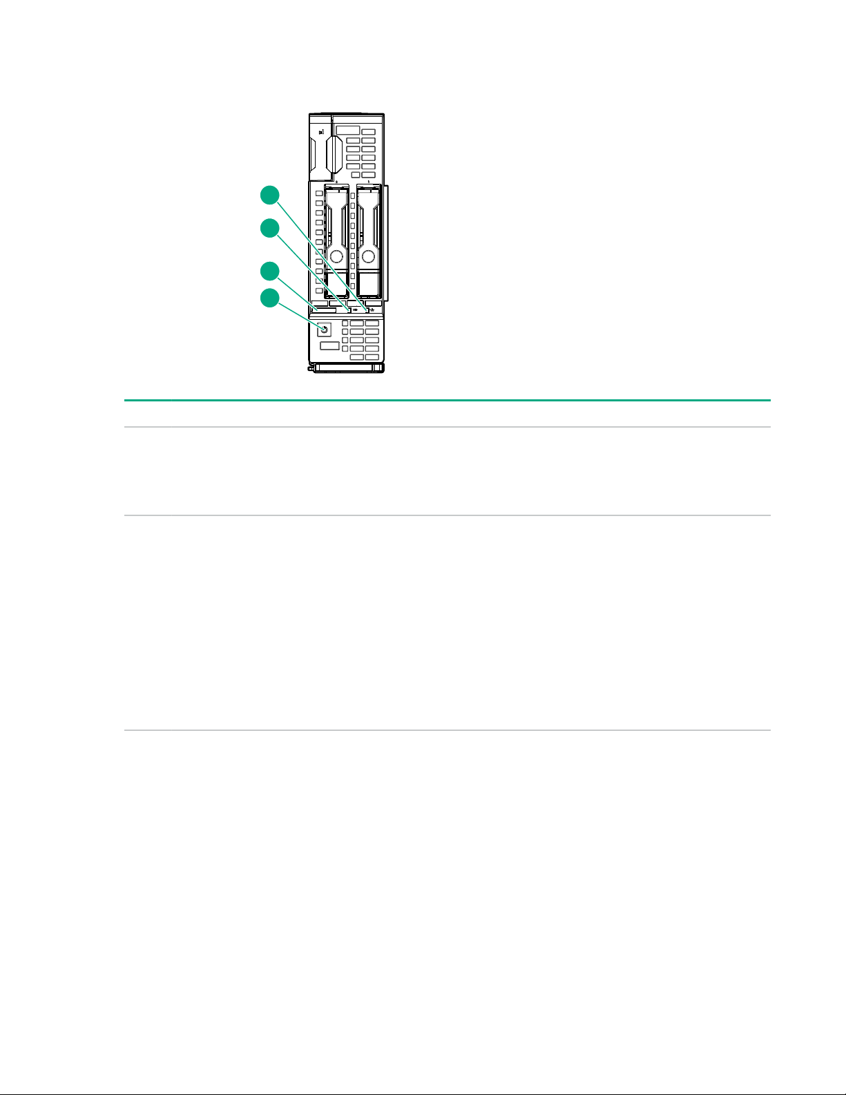
Front panel LEDs and buttons
1
2
3
4
Item Description Status
1 NIC status LED Solid green = Link to network
Flashing green (1 flash per second) = Network active
Off = No network activity
2 UID LED Solid blue = Activated
Flashing blue:
• 1 flash per second = Remote management or firmware
upgrade in progress
• 4 flashes per second = iLO manual reboot sequence initiated
• 8 flashes per second = iLO manual reboot sequence in
progress
Off = Deactivated
Table Continued
Component identification 7

Item Description Status
3 Health LED Solid green = Normal
Flashing green (1 flash per second) = iLO is rebooting
Flashing amber = System degraded
Flashing red (1 flash per second) = System critical
If the health LED indicates a degraded or critical state, review the
system IML or use iLO to review the system health status.
4 Power On/Standby button
and system power LED
Solid green = System on
Flashing green (1 flash per second) = Performing power on
sequence
Solid amber = System in standby
Off = No power present
Facility power is not present, power cord is not attached, no
power supplies are installed, power supply failure has occurred,
or the server blade is not plugged in.
Front panel LED power fault codes
The number of flashes in each sequence corresponds to the subsystem impacted by the power fault. The
following table provides a list of power fault codes, and the subsystems that are affected. Not all power
faults are used by all Server Blades.
Subsystem Front panel LED behavior
System board 1 flash
Processor 2 flashes
Memory 3 flashes
Mezzanine slots 4 flashes
FlexibleLOM 5 flashes
Removable HPE Flexible Smart Array controller/
NVMe Pass-Through
Power backplane or storage backplane 8 flashes
Serial label pull tab information
The serial label pull tab is on the front panel of the server blade. To locate the serial label pull tab, see
Front panel components on page 6. The serial label pull tab provides the following information:
• Product serial number
• iLO information
• QR code that points to mobile-friendly documentation
8 Component identification
6 flashes
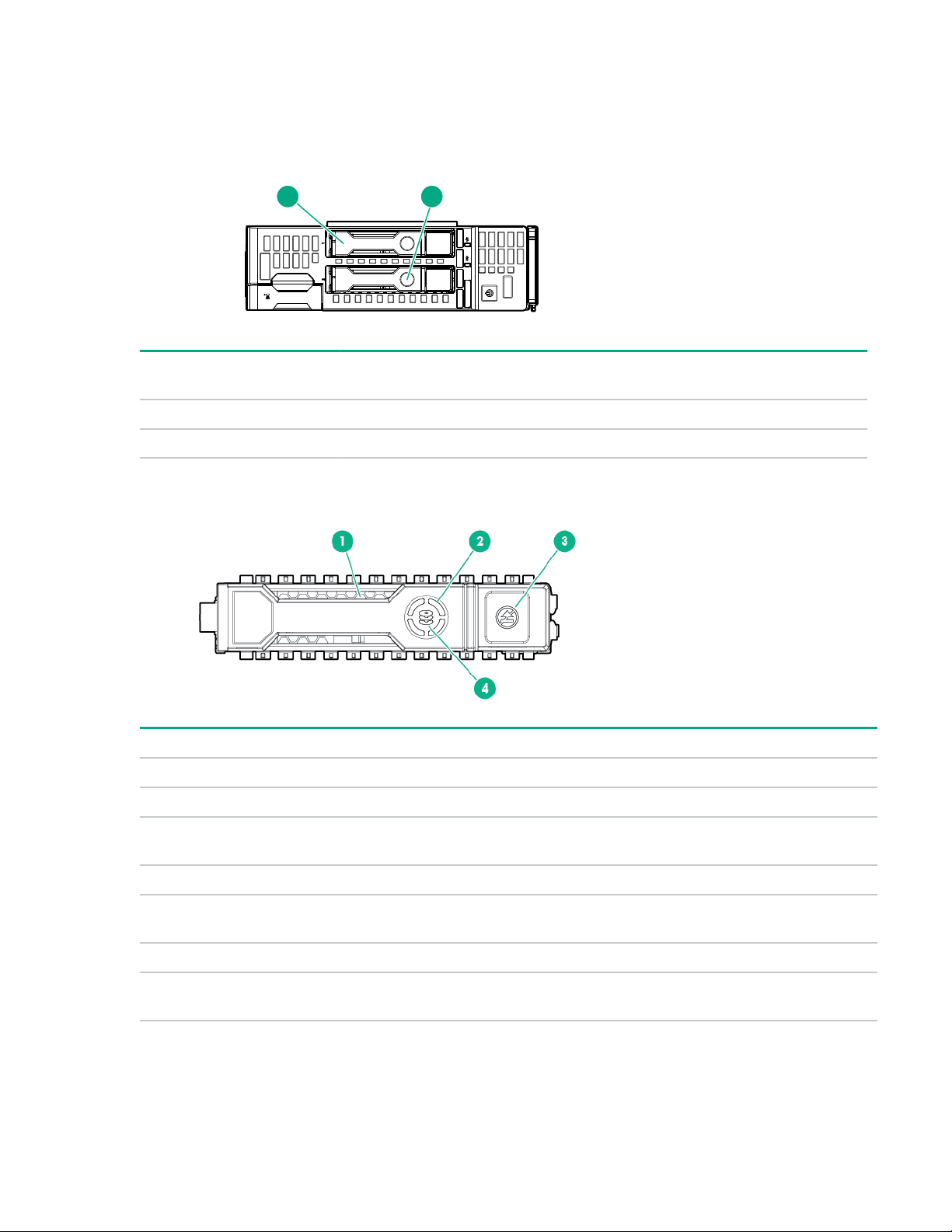
Drive numbering
1 2
Depending on the configuration, this server blade can support hard drives, SSDs, NVMe SSDs, and uFF
drives (supported in a SFF Flash Adapter) in the drive bays. Depending on the device installed, the bay
number might be different.
Item Hard drive/SSD bay
numbering
1 1 1 and 101 1
2 2 2 and 102 2
uFF drive bay
numbering
NVMe drive bay numbering
Hot-plug drive LED definitions
Item LED Status Definition
1 Locate Solid blue The drive is being identified by a host application.
Flashing blue The drive carrier firmware is being updated or requires an update.
2 Activity
ring
Off No drive activity
3 Do not
remove
Off Removing the drive does not cause a logical drive to fail.
4 Drive
status
Rotating green Drive activity
Solid white Do not remove the drive. Removing the drive causes one or more of
the logical drives to fail.
Solid green The drive is a member of one or more logical drives.
Component identification 9
Table Continued
Item LED Status Definition
Flashing green
The drive is doing one of the following:
• Rebuilding
• Performing a RAID migration
• Performing a strip size migration
• Performing a capacity expansion
• Performing a logical drive extension
• Erasing
• Spare part activation
Flashing amber/
green
Flashing amber The drive is not configured and predicts the drive will fail.
Solid amber The drive has failed.
Off The drive is not configured by a RAID controller or a spare drive.
The drive is a member of one or more logical drives and predicts the
drive will fail.
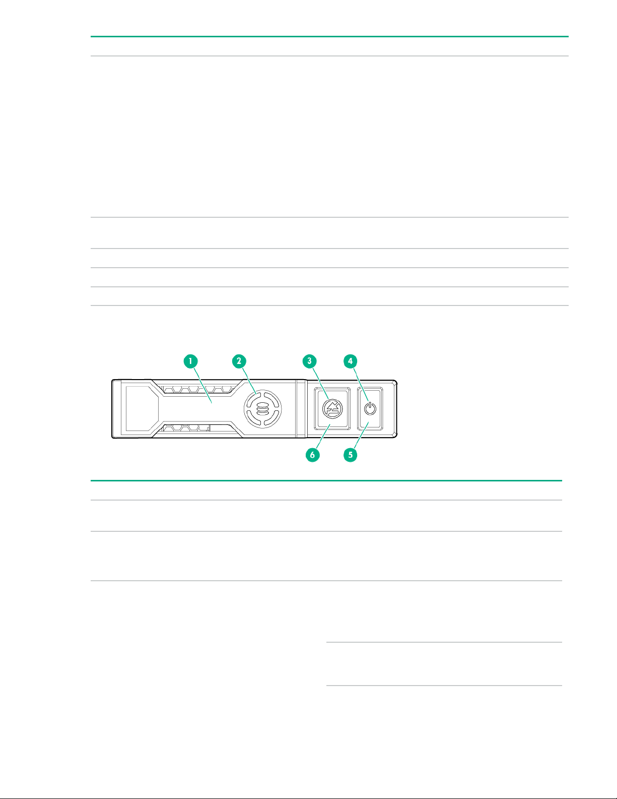
NVMe SSD components
Item Component Status Definition
1 Release lever — Ejects the NVMe drive
carrier from the cage.
2 Activity ring LED
3 Do Not Remove LED
10 Component identification
Rotating green
Off
Solid white Drive is powered on and
Flashing white Ejection request
Drive activity
No drive activity
configured in system.
Do not remove the drive.
pending. Do not remove
the drive.
Table Continued
Item Component Status Definition
Off Drive removed from the
PCIe bus and can be
ejected.
4 Power LED
5 Power button — Momentary press to
6 Do Not Remove button — Releases the release
Upon NVMe SSD insertion, an LED initiation sequence will be visible - lighting each LED in the carrier in
sequence from left to right. The sequence will cycle until the drive is recognized by the system. When the
SSD is recognized by the system - the Do Not Remove LED will be solid white and the Power LED will be
solid green.
Solid green Drive is powered on and
configured in system.
Do not remove the drive.
Flashing green Ejection request
pending. Do not remove
the drive.
Off Drive removed from the
PCIe bus and can be
ejected.
request drive removal
from PCIe bus and
ejection. Drive removal
request can be denied
by operating system.
lever for removal and
insertion.
SFF flash adapter components and LED definitions
Component identification 11
Item Component Description
1 Locate • Off—Normal
• Solid blue—The drive is being identified by a host application.
• Flashing blue—The drive firmware is being updated or
requires an update.
2 uFF drive ejection latch Removes the uFF drive when released.
3 Do not remove LED • Off—OK to remove the drive. Removing the drive does not
cause a logical drive to fail.
• Solid white—Do not remove the drive. Removing the drive
causes one or more of the logical drives to fail.
4 Drive status LED • Off—The drive is not configured by a RAID controller or a
spare drive.
• Solid green—The drive is a member of one or more logical
drives.
• Flashing green (4 Hz)—The drive is operating normally and
has activity.
• Flashing green (1 Hz)—The drive is rebuilding, erasing, or
performing a RAID migration, stripe size migration, capacity
expansion, logical drive extension, or spare activation.
5 Adapter ejection release latch
and handle
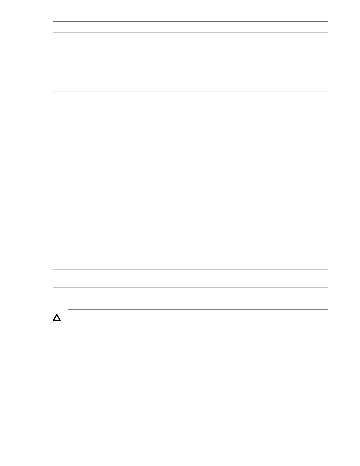
SUV cable connectors
CAUTION: Before disconnecting the SUV cable from the connector, always squeeze the release
buttons on the sides of the connector. Failure to do so can result in damage to the equipment.
• Flashing amber/green (1 Hz)—The drive is a member of one
or more logical drives that predicts the drive will fail.
• Solid amber—The drive has failed.
• Flashing amber (1 Hz)—The drive is not configured and
predicts the drive will fail.
Removes the SFF flash adapter when released.
12 Component identification
Item Connector Description
1 2 3
P2 P1
54
8
911
10
1314
15
16
43
6
12
7
1 Serial For trained personnel to connect a null modem serial cable
2 USB
1
3 Video For connecting a video monitor
1
The USB connectors on the SUV cable do not support devices that require greater than a 500mA power source.
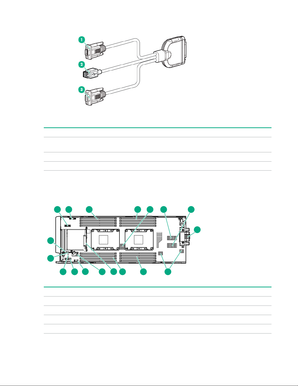
System board components
and perform advanced diagnostic procedures
For connecting up to two USB 2.0 devices
Item Description
1 System battery
2 M.2 enablement option connector
3 Processor 2 DIMM slots (8)
4 Processor 1 DIMM slots (8)
Table Continued
Component identification 13

Item Description
5 Storage controller or NVMe pass-through board connector
6 Mezzanine connector 1 (Type A mezzanine only)
7 Mezzanine connector 2 (Type A or Type B mezzanine)
8 Enclosure connector
9 FlexibleLOM connectors (2)
10 SAS/SATA or NVMe backplane
11 Internal USB 3.0 connector
12 Energy pack connector
13 Direct-connect SATA connector
14 System maintenance switch
15 microSD card slot
16 TPM connector
System maintenance switch
Position Default Function
S1 Off
S2 Off
S3 Off Reserved
S4 Off Reserved
S5 Off
S6 Off
S7 Off Reserved
S8 — Reserved
S9 Off Reserved
Off = iLO security is enabled.
On = iLO security is disabled.
Off = System configuration can be changed.
On = System configuration is locked.
Off = Power-on password is enabled.
On = Power-on password is disabled.
Off = No function.
On = ROM reads system configuration as invalid.
S10 — Reserved
S11 — Reserved
S12 — Reserved
14 Component identification
CAUTION: Clearing CMOS, NVRAM, or both deletes configuration information. Be sure to configure
Ch 6
P2 P1
Ch 5 Ch 4
Ch 3 Ch 2 Ch 1
Ch 1 Ch 2 Ch 3
Ch 4 Ch 5 Ch 6
1
2
3
4
5
6
7
8
8
7
6
5
3
2
1
4
8GB 1Rx4 DDR4-2666P -R
8GB 1 Rx4 DDR 4-2666P -R
1 2 3 4 5 6 7
the server blade properly to prevent data loss.
DIMM slot locations
DIMM slots are numbered sequentially (1 through 8) for each processor and designate the DIMM slot ID
for population rules and spare replacement.
For specific DIMM population information, see the DIMM population guidelines on the Hewlett Packard
Enterprise website (
http://www.hpe.com/docs/memory-population-rules).
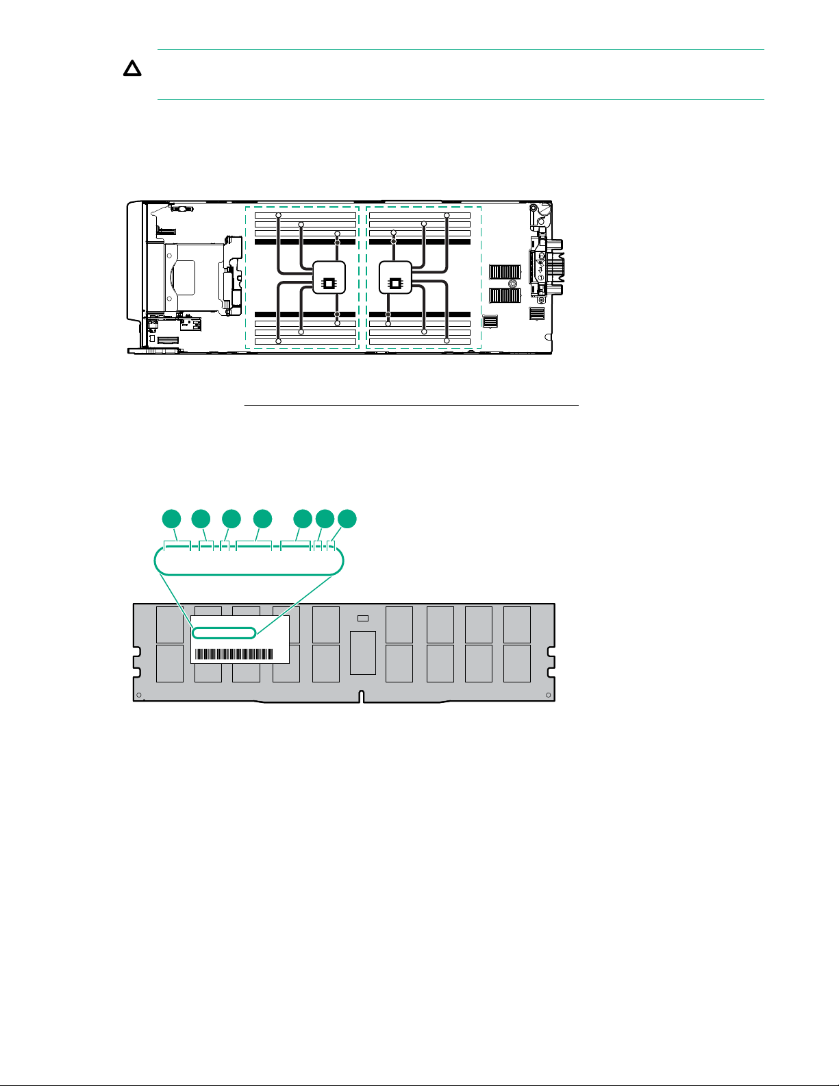
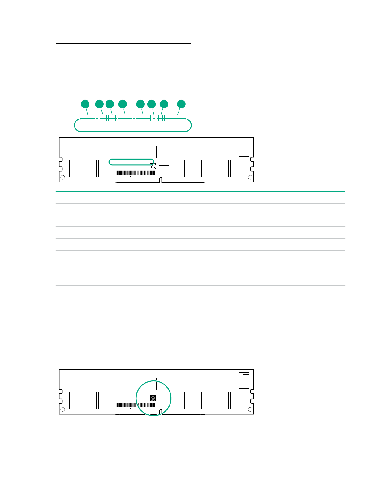
DIMM label identification
To determine DIMM characteristics, see the label attached to the DIMM. The information in this section
helps you to use the label to locate specific information about the DIMM.
Component identification 15

Item Description Example
1 Capacity
2 Rank
3 Data width on DRAM
4 Memory generation
8 GB
16 GB
32 GB
64 GB
128 GB
1R = Single rank
2R = Dual rank
4R = Quad rank
8R = Octal rank
x4 = 4-bit
x8 = 8-bit
x16 = 16-bit
PC4 = DDR4
5 Maximum memory speed
6 CAS latency
7 DIMM type
2133 MT/s
2400 MT/s
2666 MT/s
2933 MT/s
P = CAS 15-15-15
T = CAS 17-17-17
U = CAS 20-18-18
V = CAS 19-19-19 (for RDIMM, LRDIMM)
V = CAS 22-19-19 (for 3DS TSV LRDIMM)
Y = CAS 21-21-21 (for RDIMM, LRDIMM)
Y = CAS 24-21-21 (for 3DS TSV LRDIMM)
R = RDIMM (registered)
L = LRDIMM (load reduced)
16 Component identification
E = Unbuffered ECC (UDIMM)
For more information about product features, specifications, options, configurations, and compatibility, see
16GB 1Rx4 NN4-2666V-RZZZ-10
16GB 1Rx4 N N4-2666 V-RZZZ-1 0
1 2 3 74 5 6 8
the HPE DDR4 SmartMemory QuickSpecs on the Hewlett Packard Enterprise website (http://
www.hpe.com/support/DDR4SmartMemoryQS).
NVDIMM identification
NVDIMM boards are blue instead of green. This change to the color makes it easier to distinguish
NVDIMMs from DIMMs.
To determine NVDIMM characteristics, see the full product description as shown in the following example:
Item Description Definition
1 Capacity 16 GiB
2 Rank 1R (Single rank)
3 Data width per DRAM chip x4 (4 bit)
4 Memory type NN4=DDR4 NVDIMM-N
5 Maximum memory speed 2667 MT/s
6 Speed grade V (latency 19-19-19)
7 DIMM type RDIMM (registered)
8 Other —
For more information about NVDIMMs, see the product QuickSpecs on the Hewlett Packard Enterprise
website (http://www.hpe.com/info/qs).
NVDIMM 2D Data Matrix barcode
The 2D Data Matrix barcode is on the right side of the NVDIMM label and can be scanned by a cell phone
or other device.
When scanned, the following information from the label can be copied to your cell phone or device:
Component identification 17
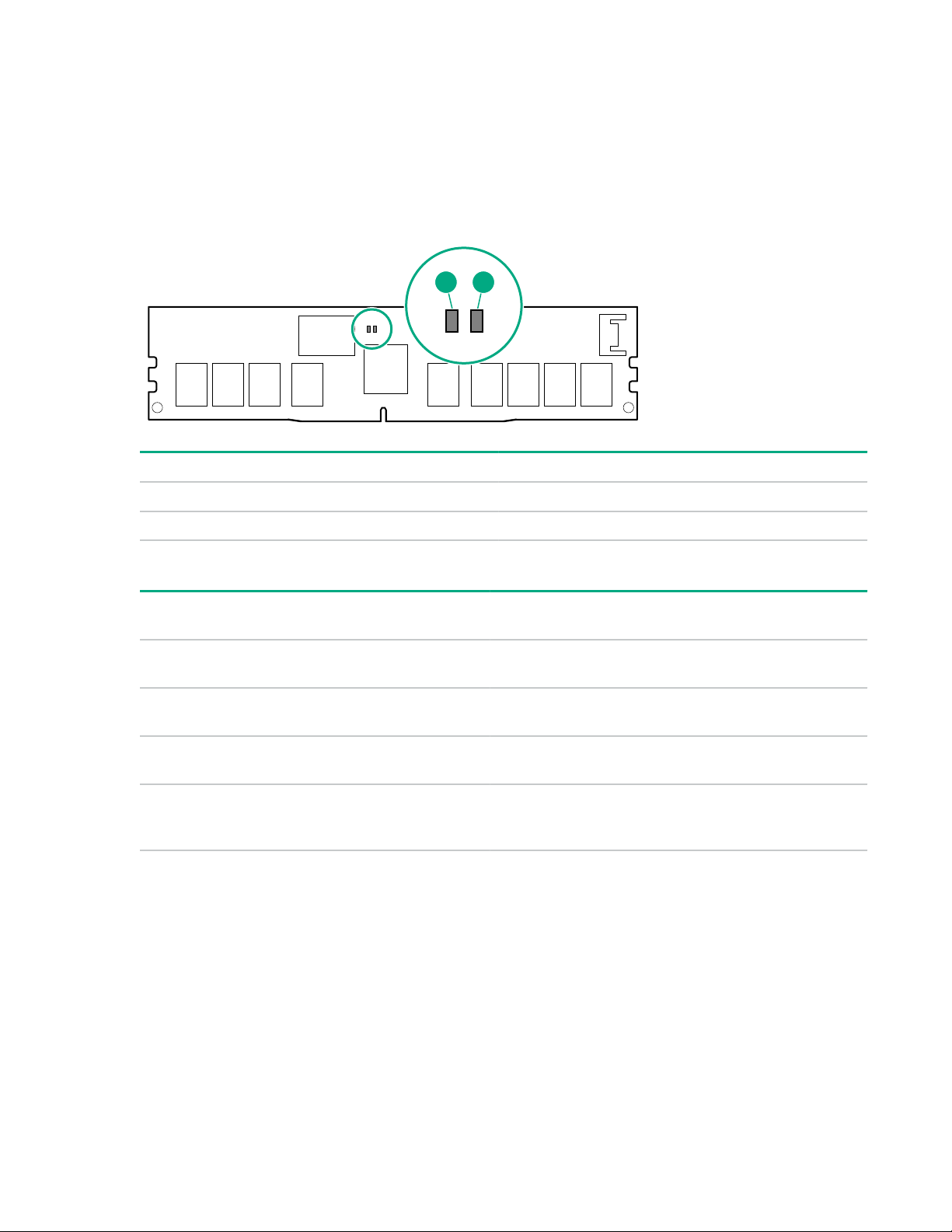
• (P) is the module part number.
1 2
• (L) is the technical details shown on the label.
• (S) is the module serial number.
Example: (P)HMN82GR7AFR4N-VK (L)16GB 1Rx4 NN4-2666V-RZZZ-10(S)80AD-01-1742-11AED5C2
NVDIMM LED identification
Item LED description LED color
1 Power LED Green
2 Function LED Blue
NVDIMM-N LED combinations
State Definition NVDIMM-N Power LED
0 AC power is on (12V rail) but the NVM
controller is not working or not ready.
1 AC power is on (12V rail) and the NVM
controller is ready.
2 AC power is off or the battery is off (12V
rail off).
3 AC power is on (12V rail) or the battery is
on (12V rail) and the NVDIMM-N is active
(backup and restore).
NVDIMM Function LED patterns
For the purpose of this table, the NVDIMM-N LED operates as follows:
• Solid indicates that the LED remains in the on state.
• Flashing indicates that the LED is on for 2 seconds and off for 1 second.
• Fast-flashing indicates that the LED is on for 300 ms and off for 300 ms.
NVDIMM-N Function
(green)
On Off
On On
Off Off
On Flashing
LED (blue)
18 Component identification
State Definition NVDIMM-N Function LED
2
3
4
1
0 The restore operation is in progress. Flashing
1 The restore operation is successful. Solid or On
2 Erase is in progress. Flashing
3 The erase operation is successful. Solid or On
4 The NVDIMM-N is armed, and the NVDIMM-N is in
normal operation.
5 The save operation is in progress. Flashing
6 The NVDIMM-N finished saving and battery is still
turned on (12 V still powered).
7 The NVDIMM-N has an internal error or a firmware
update is in progress. For more information about an
NVDIMM-N internal error, see the IML.
Mezzanine connector definitions
Item PCIe
Mezzanine connector 1 x16, Type A mezzanine card only
Mezzanine connector 2 x16, Type A or B mezzanine card
NOTE: When installing a mezzanine card option on mezzanine connector 2, processor 2 must be
installed.
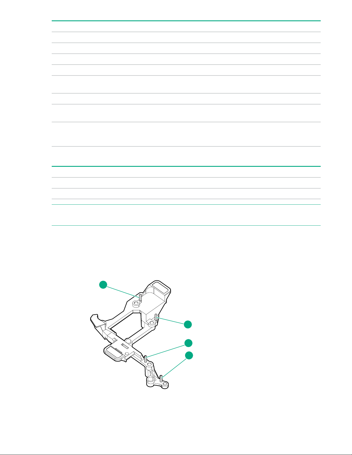
Mezzanine connector guide pin locations
Solid or On
Solid or On
Fast-flashing
The mezzanine assembly supports two mezzanine cards in this server blade. When installing a
mezzanine card into the assembly, be sure to use the guide pins associated with the mezzanine
connector.
Component identification 19

Item Description
1 and 3 Mezzanine connector 2
2 and 4 Mezzanine connector 1
20 Component identification

Operations
Power up the server blade
The OA initiates an automatic power-up sequence when the server blade is installed. If the default setting
is changed, use one of the following methods to power up the server blade:
• Use a virtual power button selection through iLO.
• Press and release the Power On/Standby button.
When the server blade goes from the standby mode to the full power mode, the system power LED
changes from amber to solid green. The health LED flashes green when the Power On/Standby Button
service is being initialized. For more information about the system power LED status, see
LEDs and buttons on page 7.
For more information about the OA, see the OA setup and installation guide on the Hewlett Packard
Enterprise website.
Power down the server blade
Procedure
• Press and release the Power On/Standby button.
Front panel
This method initiates a controlled shutdown of applications and the OS before the server blade enters
standby mode.
• Press and hold the Power On/Standby button for more than 4 seconds to force the server blade to
enter standby mode.
This method forces the server blade to enter standby mode without properly exiting applications and
the OS. If an application stops responding, you can use this method to force a shutdown.
• Use a virtual power button selection through iLO.
This method initiates a controlled remote shutdown of applications and the OS before the server blade
enters standby mode.
• Use the OA CLI to execute one of the following commands:
◦ poweroff server [bay number]
This command initiates a controlled shutdown of applications and the OS before the server blade
enters standby mode.
◦ poweroff server [bay number] force
This form of the command forces the server blade to enter standby mode without properly exiting
applications and the OS. If an application stops responding, this method forces a shutdown.
• Use the OA GUI to initiate a shutdown:
1. Select the Enclosure Information tab.
2. In the Device Bays item, select the server.
3. From the Virtual Power menu, initiate a shutdown of applications and the OS:
Operations 21
◦ For a controlled shutdown, select Momentary Press.
◦ For an emergency shutdown, select Press and Hold.
Before proceeding, verify that the server blade is in standby mode by observing that the system power
LED is amber.
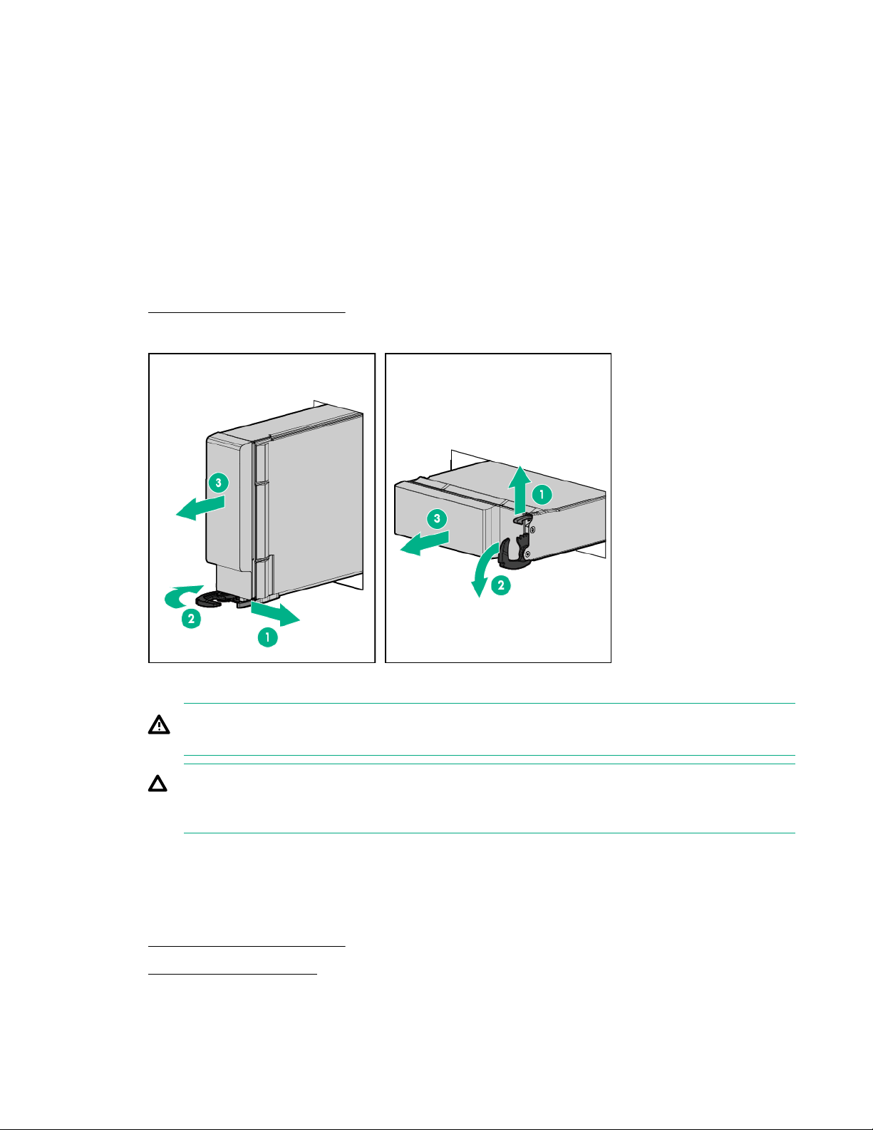
Remove the server blade
Procedure
1. Identify the proper server blade.
2. Power down the server blade on page 21.
3. Remove the server blade.
4. Place the server blade on a flat, level work surface.
WARNING: To reduce the risk of personal injury from hot surfaces, allow the drives and the
internal system components to cool before touching them.
CAUTION: To prevent damage to electrical components, properly ground the server blade
before beginning any installation procedure. Improper grounding can cause electrostatic
discharge.
Remove the access panel
Procedure
1. Power down the server blade on page 21.
2. Remove the server blade on page 22.
3. Place the server blade on a flat, level work surface.
22 Operations
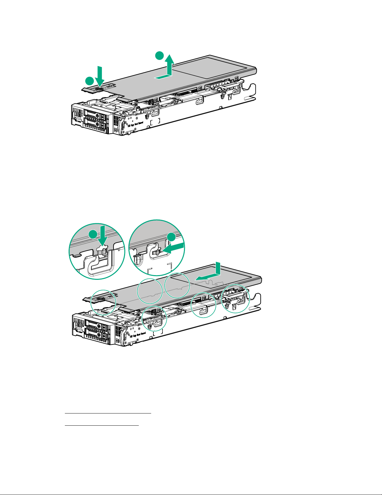
4. Press the access panel release button.
1
2
1
2
5. Slide the access panel towards the rear of the server blade, and then lift to remove the panel.
Install the access panel
Procedure
1. Align the access panel with the guides on the server blade in all six places and place the access panel
on top of the server blade.
2. Slide the access panel forward until it clicks into place.
Remove the DIMM baffles
The server contains two DIMM baffles.
Procedure
1. Power down the server blade on page 21.
2. Remove the server blade on page 22.
3. Place the server blade on a flat, level work surface.
Operations 23
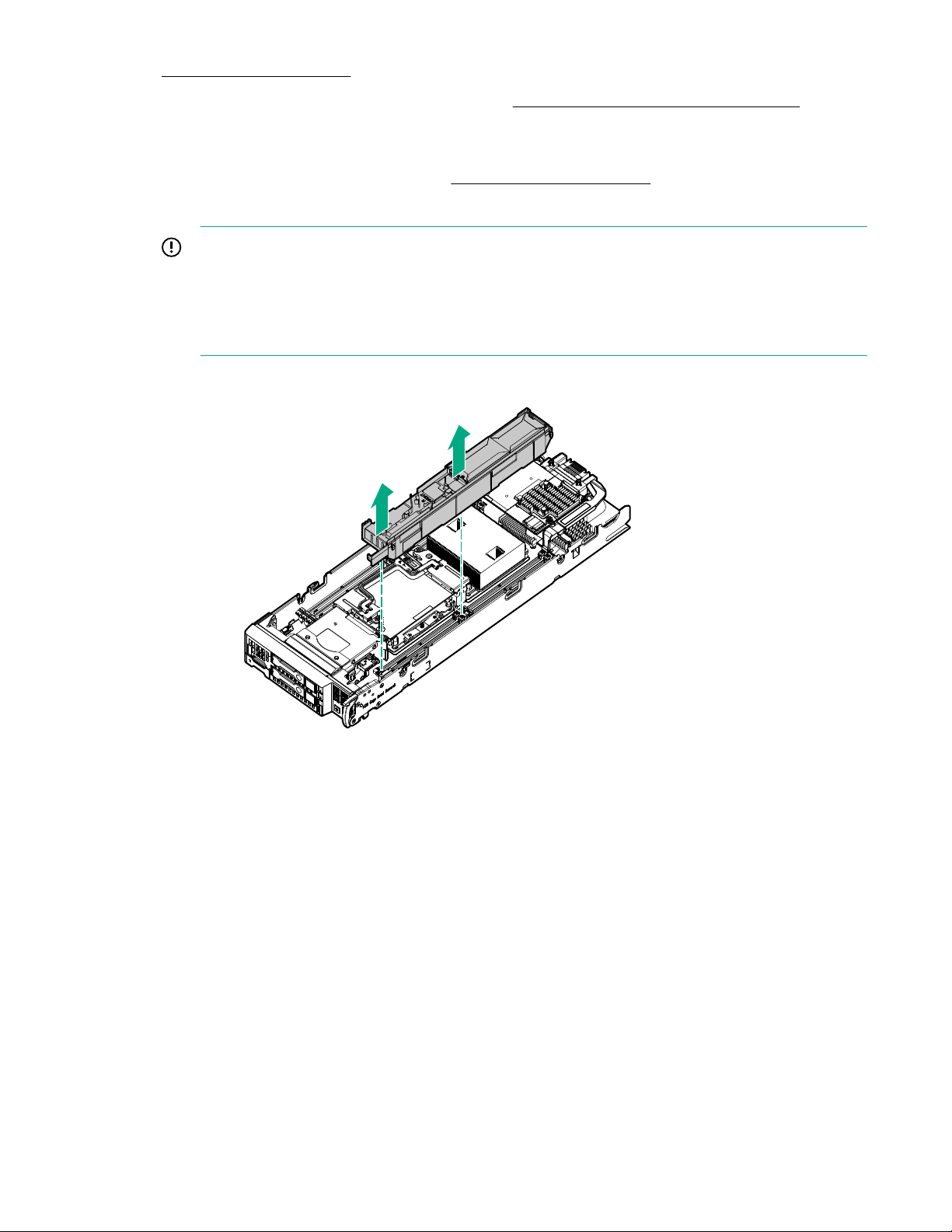
4. Remove the access panel on page 22.
5. If installed, remove the direct connect SATA cable (Remove the direct connect SATA cable on page
31).
6. If installed, remove the internal USB drive.
To locate the internal USB connector, see System board components on page 13.
7. Remove one or more DIMM baffles:
IMPORTANT: When removing a DIMM baffle, do not remove the following options when installed
on the DIMM baffle:
• M.2 enablement option (left DIMM baffle)
• HPE Smart Storage Battery (right DIMM baffle)
• DIMM baffle (right side)
• DIMM baffle (left side)
24 Operations
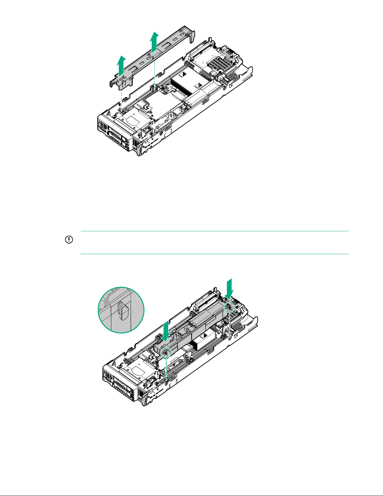
Install the DIMM baffles
The server has two DIMM baffles.
Procedure
1. Align and install the DIMM baffle:
IMPORTANT: When installing each DIMM baffle, be sure that the alignment tabs engage with
the side of the server blade.
• DIMM baffle (right side)
• DIMM baffle (left side)
Operations 25
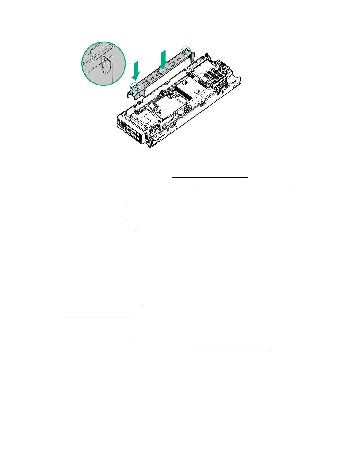
2. If removed, install the internal USB drive.
To locate the internal USB connector, see System board components on page 13.
3. If removed, install the direct connect SATA cable (Install the direct connect SATA cable on page
31.
4. Install the access panel on page 23.
5. Install the server blade on page 42.
6. Power up the server blade on page 21.
Remove an M.2 SSD from the M.2 riser board
Prerequisites
To remove an M.2 SSD from the M.2 riser, you need a No. 1 Phillips screwdriver.
Procedure
1. Power down the server blade on page 21.
2. Remove the server blade on page 22.
3. Place the server blade on a flat, level work surface.
4. Remove the access panel on page 22.
5. Remove the left DIMM baffle from the server blade (Remove the DIMM baffles on page 23).
6. Remove the M.2 SSD from the M.2 riser board. Use a No. 1 Phillips screwdriver to disengage the
screw.
26 Operations
1
2
3
7. If necessary, repeat the M.2 SSD removal procedure for a second drive.
2
1
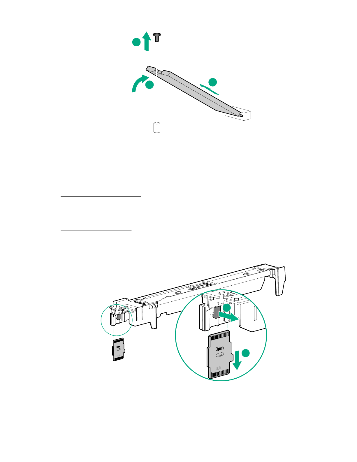
Remove the M.2 interposer board and the M.2 riser board
Procedure
1. Power down the server blade on page 21.
2. Remove the server blade on page 22.
3. Place the server blade on a flat, level work surface.
4. Remove the access panel on page 22.
5. Remove the left DIMM baffle from the server blade (Remove the DIMM baffles on page 23).
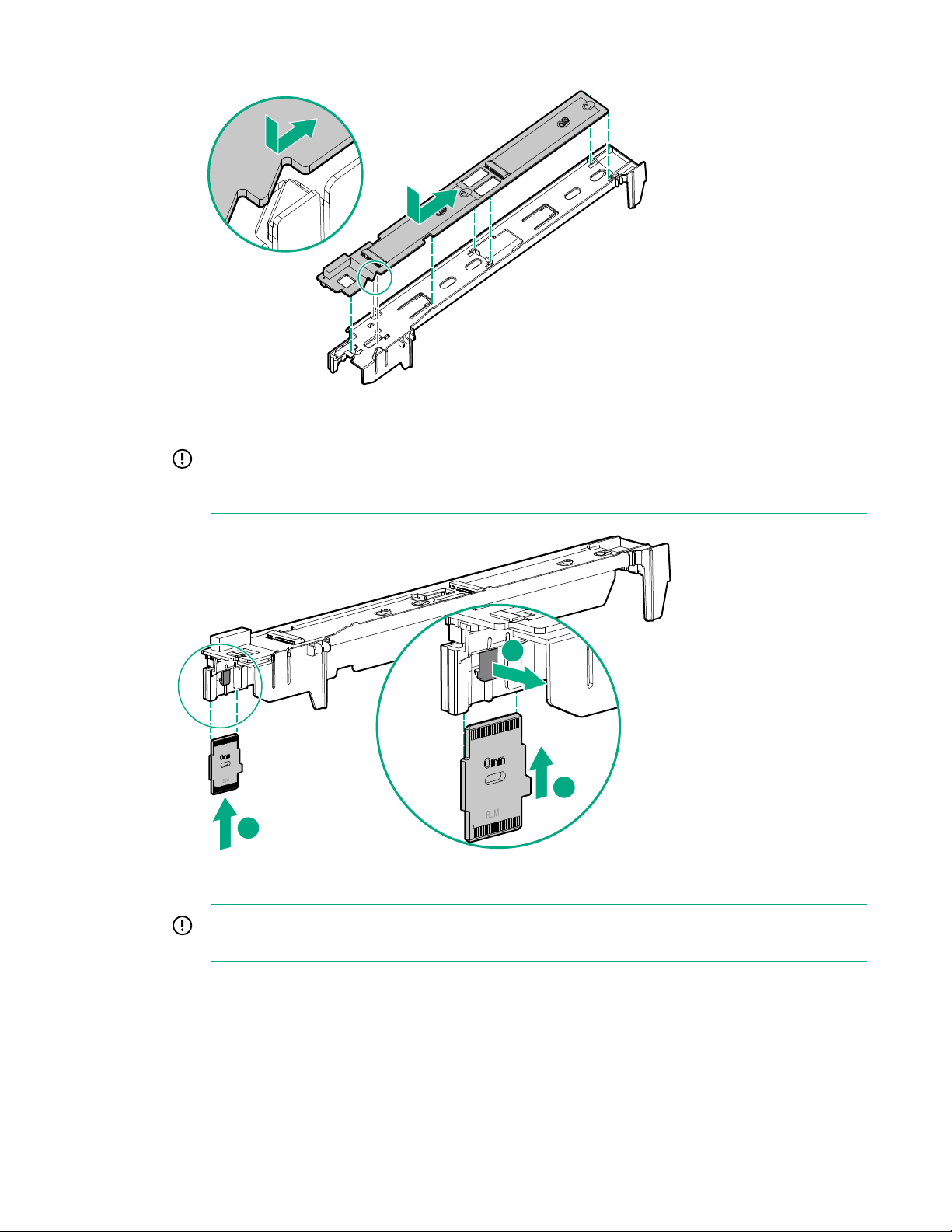
6. Remove the M.2 interposer board.
7. Remove the M.2 riser board from the left DIMM baffle.
Operations 27
1
2
2
Relocate the PEM nut and rubber stopper
This procedure is required if the PEM nut and rubber stoppers must be relocated to support the length of
the M.2 SSDs being installed.
Prerequisites
To remove the M.2 SSDs from the M.2 riser, you need a No. 1 Phillips screwdriver.
Procedure
1. Power down the server blade on page 21.
2. Remove the server blade on page 22.
3. Place the server blade on a flat, level work surface.
4. Remove the access panel on page 22.
5. Remove the left DIMM baffle.
See Remove the DIMM baffles on page 23.
6. Remove the M.2 interposer board and the M.2 riser board on page 27.
7. If installed, Remove an M.2 SSD from the M.2 riser board on page 26.
8. Remove the rubber stoppers from the M.2 riser.
28 Operations
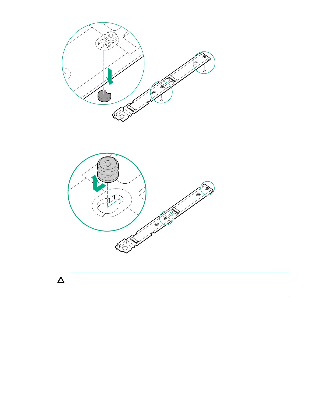
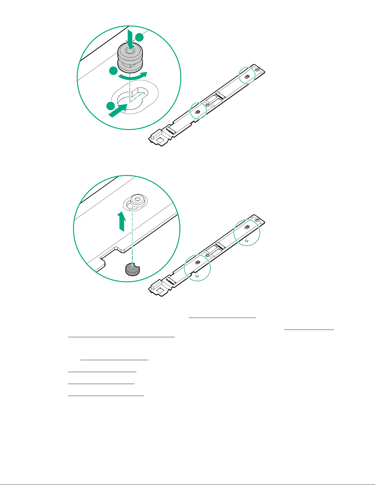
9. Remove the PEM nuts from the M.2 riser.
10. Install the PEM nuts in the new location on the M.2 riser.
CAUTION: Always install the PEM nut with the thicker edge on top of the M.2 riser and the
thinner edge on the bottom of the M.2 riser. Failure to install the PEM nut in the proper
orientation can cause damage to the components.
Operations 29
1
2
3
11. Install the rubber stoppers in the new locations to secure the PEM nuts in the M.2 riser.
12. Install the M.2 SSDs on the M.2 riser board (Installing the M.2 SSDs on page 59).
13. Install the M.2 riser board and the M.2 interposer board on the left DIMM baffle (Installing the M.2
riser board and M.2 interposer board on page 57).
14. Install the left DIMM baffle.
See Install the DIMM baffles on page 25.
15. Install the access panel on page 23.
16. Install the server blade on page 42.
17. Power up the server blade on page 21.
30 Operations

Remove the direct connect SATA cable
1
2
3
4
5
Prerequisites
To remove the direct connect SATA cable, you need a T-15 Torx screwdriver.
Procedure
1. Power down the server blade on page 21.
2. Remove the server blade on page 22.
3. Place the server blade on a flat, level work surface.
4. Remove the access panel on page 22.
5. Remove the direct connect SATA cable.
Install the direct connect SATA cable
Prerequisites
To install the direct connect SATA cable, you need a T-15 Torx screwdriver.
Procedure
1. Power down the server blade on page 21.
2. Remove the server blade on page 22.
3. Place the server blade on a flat, level work surface.
4. Remove the access panel on page 22.
5. Install the direct connect SATA cable.
Operations 31

3
2
1
4
Remove the mezzanine assembly
1
2
3
Procedure
1. Power down the server blade on page 21.
2. Remove the server blade on page 22.
3. Place the server blade on a flat, level work surface.
4. Remove the access panel on page 22.
5. Remove the mezzanine assembly.
32 Operations

Install the mezzanine assembly
2
1
1
Procedure
1. Install the mezzanine assembly
2. Install the access panel on page 23.
3. Install the server blade on page 42.
4. Power up the server blade on page 21.
Remove the FlexibleLOM
Procedure
1. Power down the server blade on page 21.
2. Remove the server blade on page 22.
3. Place the server blade on a flat, level work surface.
4. Remove the access panel on page 22.
5. Remove the mezzanine assembly on page 32.
6. Use the FlexibleLOM handle to remove the FlexibleLOM from the system board.
Operations 33

Remove the storage controller or NVMe pass-through
1
2
board
1. Back up all server blade data.
2. Power down the server blade on page 21.
3. Remove the server blade on page 22.
4. Place the server blade on a flat, level work surface.
5. Remove the access panel on page 22.
6. Prepare the storage controller/NVMe pass-through board for removal.
7. Remove the storage controller/NVMe pass-through board.
34 Operations

Remove an NVMe SSD
Procedure
1. Observe the LED status of the drive and determine if it can be removed.
2. Remove the drive:
a. Press the power button.
The Do Not Remove button illuminates and flashes. Wait until the flashing stops and the Do Not
Remove button is no longer illuminated.
b. When the Do Not Remove button is no longer illuminated, press the Do Not Remove button and
then remove the drive.
Remove a SAS or SATA drive
1. Determine status of drives from LED Definitions.
For more information, see Hot-plug drive LED definitions on page 9.
2. Back up all server blade data on the drive.
3. Remove the drive.
Operations 35

Remove the front panel/drive cage assembly
Prerequisites
To remove the front panel/drive cage assembly, you need a T-15 Torx screwdriver.
Procedure
1. Power down the server blade on page 21.
2.
Remove the server blade on page 22.
3. Place the server blade on a flat, level work surface.
4. Remove the access panel on page 22.
5. Do one of the following:
• Remove the storage controller or the NVMe passthrough board, if installed (Remove the storage
controller or NVMe pass-through board on page 34).
• Remove the direct connect SATA cable on page 31.
6. If installed, remove the internal USB drive. To locate the internal USB connector, see System board
components on page 13.
7. Remove the DIMM baffles on page 23.
8. Remove the front panel/drive cage assembly:
a. Extend the serial label pull tab from the front of the server blade.
b. Remove the two T-15 screws from the front panel/drive cage assembly.
c. Remove the component.
36 Operations
IMPORTANT: When removing a DIMM baffle, do not remove the following options when installed
on the DIMM baffle:
• M.2 enablement option (left DIMM baffle)
• HPE Smart Storage Battery (right DIMM baffle)

2
2
1
3
Install the front panel/drive cage assembly
Prerequisites
To install the front panel/drive cage assembly, you need a T-15 Torx screwdriver.
Procedure
1. Install the front panel/drive cage assembly:
a. Extend the serial label pull tab from the front of the server blade.
b. Align the pins on the chassis and slide the front panel/drive cage assembly into the server blade.
c. Secure the assembly with two T-15 screws.
d. Close the serial label pull tab.
Operations 37

2
3
3
1
4
2. Install the DIMM baffles on page 25.
3. Do one of the following:
• Install the storage controller (HPE Smart Array P204i SR Gen10 Controller option on page 48)
or the NVMe pass-through board.
• Install the direct connect SATA cable on page 31.
4. Install the access panel on page 23.
5. Install the server blade on page 42.
6. Power up the server blade on page 21.
38 Operations

Setup
Overview
Installation of a server blade requires the following steps.
Procedure
1. Install and configure a BladeSystem c-Class enclosure.
2. Install any server blade options.
3. Install interconnect modules in the enclosure.
4. Connect the interconnect modules to the network.
5. Install a server blade.
6. Complete the server blade configuration.
Server blade warnings and cautions
WARNING: To reduce the risk of shock or injury from high-current electrical energy, do not remove
the server blade access panel and then install the server blade into the enclosure.
WARNING: To reduce the risk of personal injury from hot surfaces, allow the drives and the internal
system components to cool before touching them.
CAUTION: Do not operate the server blade with the access panel removed. Operating the server
blade in this manner results in improper airflow and improper cooling that can lead to thermal
damage.
CAUTION: When performing non-hot-plug operations, you must power down the server blade
and/or the system. However, it might be necessary to leave the server blade powered up when
performing other operations, such as hot-plug installations or troubleshooting.
WARNING: To reduce the risk of fire or burns after removing the energy pack:
• Do not disassemble, crush, or puncture the energy pack.
• Do not short external contacts.
• Do not dispose of the energy pack in fire or water.
After power is disconnected, battery voltage might still be present for 1s to 160s.
Installing an HPE BladeSystem c-Class enclosure
Before performing any server blade-specific procedures, install an HPE BladeSystem c-Class enclosure.
The most current documentation for the server blade and other BladeSystem components is available on
the Hewlett Packard Enterprise website.
Setup 39

Preparing the enclosure
Each HPE BladeSystem enclosure ships with device bay dividers to support half-height devices. If the
dividers have been removed, always reinstall the dividers before installing half-height devices and device
bay blanks. For more information on installing the device bay dividers, see the enclosure setup and
installation guide.
Prerequisites
Review the following alerts before installing the enclosure.
CAUTION: When installing half-height blades in a quadrant, always install a divider in that quadrant.
Failure to install the divider can result in damage to the connectors on the server blades.
CAUTION: To prevent improper cooling and thermal damage, do not operate the server blade or the
enclosure unless all recommended drive and device bays are populated with either a component or
a blank.
IMPORTANT: For optimal cooling and system performance, configure the HPE BladeSystem c7000
enclosure with 10 fans.
Installing server blade options
Before installing and initializing the server blade, install any server blade options, such as an additional
processor, hard drive, or mezzanine card. For server blade options installation information, see
"Hardware options installation."
Installing interconnect modules
For specific steps to install interconnect modules, see the documentation that ships with the interconnect
module.
Interconnect bay numbering and device mapping
HPE BladeSystem c7000 Enclosure
40 Setup
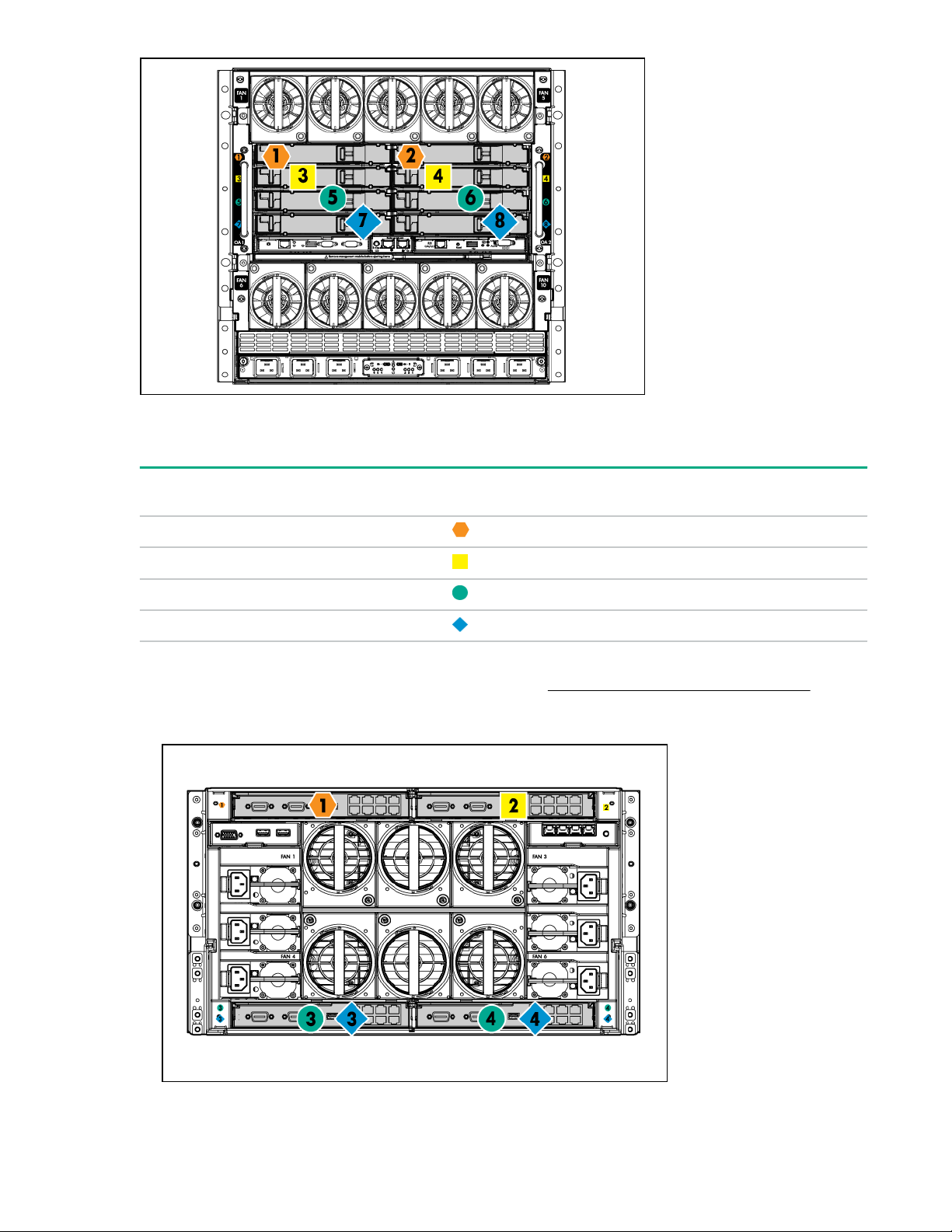
To support network connections for specific signals, install an interconnect module in the bay
corresponding to the FlexibleLOM or mezzanine signals.
Server blade
signal
FlexibleLOM 1 and 2
Mezzanine 1 3 and 4
Mezzanine 2 5 and 6
Mezzanine 2 7 and 8
For detailed port mapping information, see the BladeSystem enclosure installation poster or the
BladeSystem enclosure setup and installation guide on the Hewlett Packard Enterprise website.
• HPE BladeSystem c3000 Enclosure
Interconnect bay Interconnect bay labels
Setup 41

Server blade
signal
FlexibleLOM 1 —
Mezzanine 1 2 Four-port cards connect to bay 2.
Interconnect bay
number
Interconnect bay
label
Notes
Mezzanine 2 3 and 4
Connecting to the network
To connect the BladeSystem to a network, each enclosure must be configured with network interconnect
devices to manage signals between the server blades and the external network.
Two types of interconnect modules are available for BladeSystem c-Class enclosures:
• Pass-Thru modules
• Switch modules
For more information about interconnect module options, see the Hewlett Packard Enterprise website.
IMPORTANT: To connect to a network with a Pass-Thru module, always connect the Pass-Thru
module to a network device that supports Gigabit or 10 Gb speed, depending on the corresponding
Pass-Thru model.
Install the server blade
◦ Four-port cards
◦ Ports 1 and 3 connect to bay 3.
◦ Ports 2 and 4 connect to bay 4.
42 Setup
CAUTION: To prevent improper cooling and thermal damage, do not operate the server blade or the
enclosure unless all device bays are populated with either a component or a blank.
CAUTION: Failure to install the divider in a quadrant when installing half-height blades can result in
damage to the connectors on the server blade.
For the best possible BladeSystem and Virtual Connect experience, and to prevent a future reboot,
Hewlett Packard Enterprise requires updating the Onboard Administrator and Virtual Connect to the
correct version before installing an HPE ProLiant Gen10 server blade. The version information is on the
tag on the front of the server blade.
For more information on this and other specific firmware and driver requirements, as well as the latest
firmware and driver versions, download the latest SPP from the Hewlett Packard Enterprise website
(http://www.hpe.com/servers/spp/download).
Procedure
1. Remove the device bay blank.
Retain the blank for future use.
2. Remove the enclosure connector cover.
Retain the cover for future use.
3. Install the server blade.
Setup 43

Completing the configuration
To complete the server blade and BladeSystem configuration, see the overview card that ships with the
enclosure.
44 Setup

Hardware options installation
Introduction
Install any hardware options before initializing the server. For options installation information, see the
option documentation. For server-specific information, use the procedures in this section.
If multiple options are being installed, read the installation instructions for all the hardware options to
identify similar steps and streamline the installation process.
WARNING: To reduce the risk of personal injury from hot surfaces, allow the drives and the internal
system components to cool before touching them.
CAUTION: To prevent damage to electrical components, properly ground the server before
beginning any installation procedure. Improper grounding can cause electrostatic discharge.
Drive bay options
Two SFF drive bays are on the front panel of the server blade. The following options are supported in the
drive bays:
• SFF SAS hard drives
• SFF SATA hard drives
• SFF SAS SSDs
• SFF SATA SSDs
• NVMs SSDs
• uFF SATA SSDs with the SFF Flash Adapter
Ensure that the server blade is configured properly when installing the drive options. For example, be
sure that the drive option is configured with the proper backplane and other required components.
Installing the SAS and SATA drive options
The server blade supports hot plug SAS and SATA hard drives and hot plug SAS and SATA SSDs.
Prerequisites
To support SAS and SATA hard drives or SSDs, install the SAS/SATA HDD backplane with one of the
following:
• Direct connect SATA cable (supports SATA drives only)
• HPE Smart Array P204i SR Gen10 Controller (supports both SAS and SATA drives)
Procedure
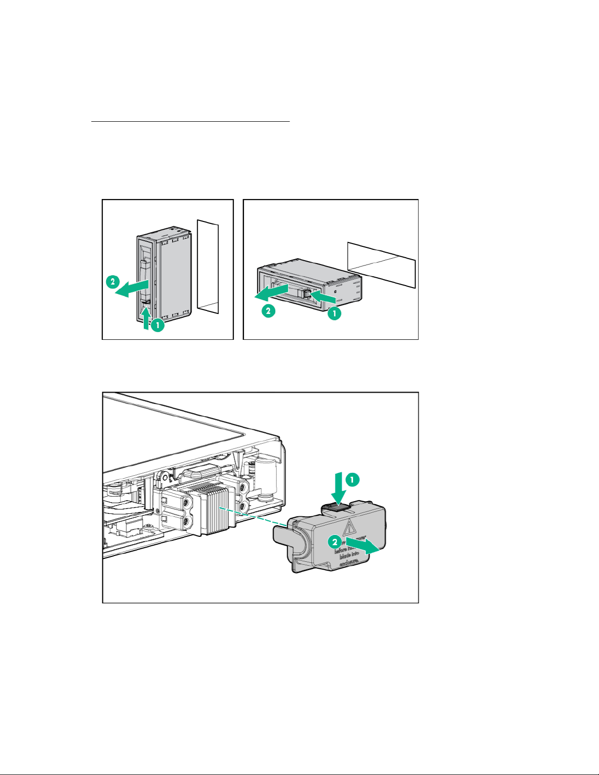
1. Remove the drive blank.
Hardware options installation 45

2. Prepare the drive.
3. Install the drive.
4. Determine the status of the drive from the drive LED definitions.
For more information, see Hot-plug drive LED definitions on page 9.
Installing the NVMe SSD options
The server blade supports hot-plug NVMe SSDs when configured for NVMe drive support.
Prerequisites
Before installing an NVMe SSD into a server blade, the server blade must be configured with the
following components:
• NVMe pass-through board
• NVMe backplane
Procedure
1. Remove the drive blank.
46 Hardware options installation

2. Press the Do Not Remove button to release the Release lever.
3. Install the drive.
4. Determine the status of the drive.
For more information, see the NVMe SSD components on page 10.
Installing the SFF Flash Adapter option
CAUTION: To prevent improper cooling and thermal damage, do not operate the server blade or the
enclosure unless all device bays are populated with either a component or a blank.
Prerequisites
To support uFF drives and the SFF Flash Adapter option, install the SAS/SATA HDD backplane with one
of the following:
• Direct connect SATA cable
• HPE Smart Array P204i SR Gen10 Controller
Procedure
1. Remove the drive blank.
Hardware options installation 47
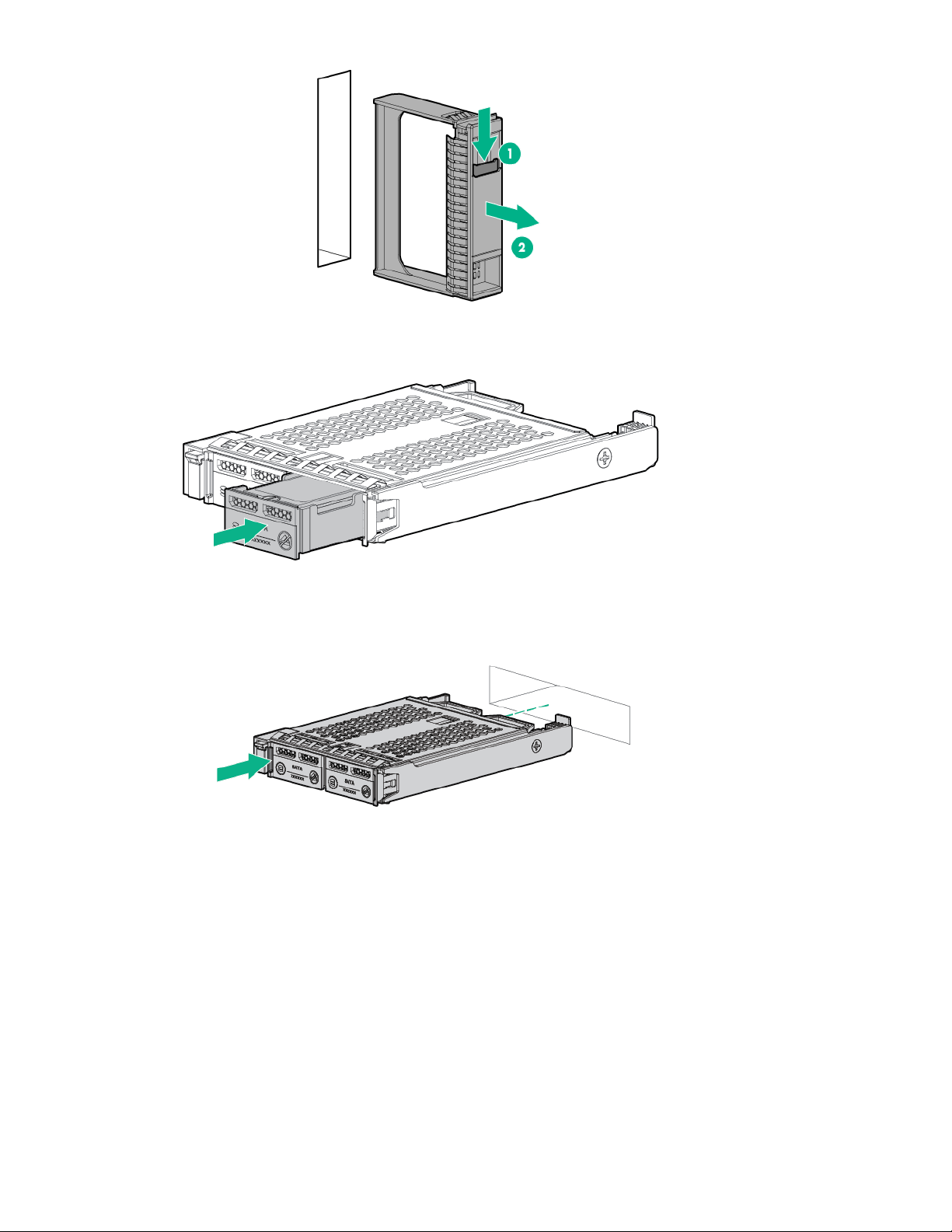
2. Install the uFF drives in the SFF Flash Adapter.
3. Install the SFF Flash Adapter by pushing firmly near the left-side adapter ejection handle until the
latching spring engages in the drive bay.
HPE Smart Array P204i SR Gen10 Controller option
When the HPE Smart Array P204i SR Gen10 Controller is installed, this server blade supports the
following options:
• Up to two SAS or SATA SSDs
• Up to two SAS or SATA hard drives
• Up to two SFF Flash Adapters (up to 4 uFF drives)
48 Hardware options installation

Prerequisites
1
2
To support this storage controller, the SAS/SATA backplane is installed on the server blade. For server
blades that support NVMe drives, an NVMe backplane is installed and an NVMe passthrough board will
be installed in this location.
Procedure
1. Back up all server blade data.
2. Power down the server blade on page 21.
3. Remove the server blade on page 22.
4. Place the server blade on a flat, level work surface.
5. Remove the access panel on page 22.
6. Remove the direct connect SATA cable, if installed (Remove the direct connect SATA cable on
page 31).
7. Prepare the storage controller for installation.
8. Align the storage controller with the alignment pins and lower it onto the connector.
Hardware options installation 49
9. Close the storage controller handle to seat the storage controller on the connector.
1
2
10. Install the access panel on page 23.
11. Install the server blade on page 42.
12. Power up the server blade on page 21.
HPE Smart Storage Battery
The HPE Smart Storage Battery supports the following devices:
HPE Smart Array SR controllers
A single 96W battery can support up to 24 devices.
After the battery is installed, it might take up to two hours to charge. Controller features requiring backup
power are not re-enabled until the battery is capable of supporting the backup power.
50 Hardware options installation

Installing the HPE Smart Storage Battery
WARNING: The server blade may contain internal replaceable battery cells or battery packs. A risk
of fire, burns, or explosions exists if the battery pack is not properly handled. To reduce the risk of
personal injury:
• Do not attempt to recharge the battery outside of the installed application.
• Do not expose the battery to temperatures higher than 60°C (140°F).
• Do not disassemble, crush, puncture, short external contacts, or dispose of the battery in fire or
water.
• Replace only with the Hewlett Packard Enterprise spare battery designated for this product.
Dispose of used batteries according to the manufacturer's instructions and local disposal
requirements.
• For battery holders (for example, coin cells), observe the correct polarity when changing the
battery/cell. A danger of explosion exists if the battery is installed incorrectly.
System ROM and firmware messages may display "energy pack" in place of "Smart Storage Battery."
Energy pack refers to both HPE Smart Storage Batteries and HPE Smart Storage Hybrid Capacitors.
Procedure
1. Power down the server blade on page 21.
2. Remove the server blade on page 22.
3. Place the server blade on a flat, level work surface.
4. Remove the access panel on page 22.
5. If installed, remove the direct connect SATA cable (Remove the direct connect SATA cable on
page 31).
6. If installed, remove the internal USB drive.
To locate the internal USB connector, see System board components on page 13.
7. Remove the right DIMM baffle (Remove the DIMM baffles on page 23).
8. Install the HPE Smart Storage Battery on the right DIMM baffle.
Hardware options installation 51

1
2
3
9. Route the cable on the right DIMM baffle.
IMPORTANT: When installing each DIMM baffle, be sure that the alignment tabs engage with
the side of the server blade.
10. Align and install the DIMM baffle.
Press down on the cable connector to fully seat the HPE Smart Storage Battery cable connector to
the system board.
52 Hardware options installation

11. If removed, install the direct connect SATA cable (Install the direct connect SATA cable on page
31).
12. If removed, install the internal USB drive.
To locate the internal USB connector, see System board components on page 13.
13. Install the access panel on page 23.
14. Install the server blade on page 42.
15. Power up the server blade on page 21.
Mezzanine card option
Optional mezzanine cards are classified as Type A mezzanine cards and Type B mezzanine cards. The
type of the mezzanine card determines where it can be installed in the server blade.
• Install Type A mezzanine cards on Mezzanine 1 connector or Mezzanine 2 connector.
• Install Type B mezzanine cards on Mezzanine 2 connector.
Before installing the mezzanine card, be sure to review the following:
• System board components on page 13 for mezzanine connector location
• Mezzanine connector definitions on page 19
• Mezzanine connector guide pin locations on page 19
• Interconnect bay numbering and device mapping on page 40
When installing a mezzanine option on mezzanine connector 2, processor 2 must be installed.
Optional mezzanine cards enable external storage, network connectivity, or provide Fiber Channel
support.
Installing the mezzanine card option
Prerequisites
To install the mezzanine card option, you need a T-15 Torx screwdriver.
Hardware options installation 53

Procedure
1. Power down the server blade on page 21.
2. Remove the server blade on page 22.
3. Place the server blade on a flat, level work surface.
4. Remove the access panel on page 22.
5. Remove the mezzanine assembly on page 32.
6. Align the mezzanine card using the appropriate guide pins on the mezzanine assembly.
7. Install the mezzanine card in the mezzanine assembly.
8. Align the mezzanine assembly with the guide pins on the system board, and then install the
mezzanine assembly on the system board.
Press firmly on the mezzanine assembly handles, and then close the mezzanine assembly latch.
54 Hardware options installation

9. Install the access panel on page 23.
10. Install the server blade on page 42.
11. Power up the server blade on page 21.
FlexibleLOM option
Installing the FlexibleLOM
Procedure
1. Power down the server blade on page 21.
2. Remove the server blade on page 22.
3. Place the server blade on a flat, level work surface.
4. Remove the access panel on page 22.
5. Remove the mezzanine assembly on page 32.
6. Install the FlexibleLOM.
Hardware options installation 55

7. Install the mezzanine assembly on page 33.
1
2
8. Install the access panel on page 23.
9. Install the server blade on page 42.
10. Power up the server blade on page 21.
M.2 enablement option
The M.2 enablement option consists of an M.2 riser and an M.2 interposer board that installs on the left
DIMM baffle. When the option is installed, the server blade supports up to two M.2 SSDs.
The M.2 riser board can support both 2280 and 22110 M.2 SSD options. If the M.2 riser is not configured
for the correct length of the M.2 SSDs being installed, relocate the PEM nut and rubber stoppers to the
location that support the drives being installed (Relocate the PEM nut and rubber stopper on page 28).
Figure 1: M.2 SSD PEM nut locations
56 Hardware options installation

1. Supports M.2 2280 SSD installation
2. Supports M.2 22110 SSD installation
Installing the M.2 riser board and M.2 interposer board
The M.2 riser board supports two M.2 SSDs. This server blade does not support mixing M.2 SSD sizes or
bus protocols.
Prerequisites
To install the M.2 SSDs on the M.2 riser board, you need a No. 1 Phillips screwdriver.
Procedure
1. Power down the server blade on page 21.
2. Remove the server blade on page 22.
3. Place the server blade on a flat, level work surface.
4. Remove the access panel on page 22.
5. Remove the left DIMM baffle.
6. Verify that the PEM nuts and rubber stoppers are in the correct location to support the length of the
M.2 SSDs being installed. Relocate the PEM nuts and rubber stoppers, if necessary.
See Relocate the PEM nut and rubber stopper on page 28.
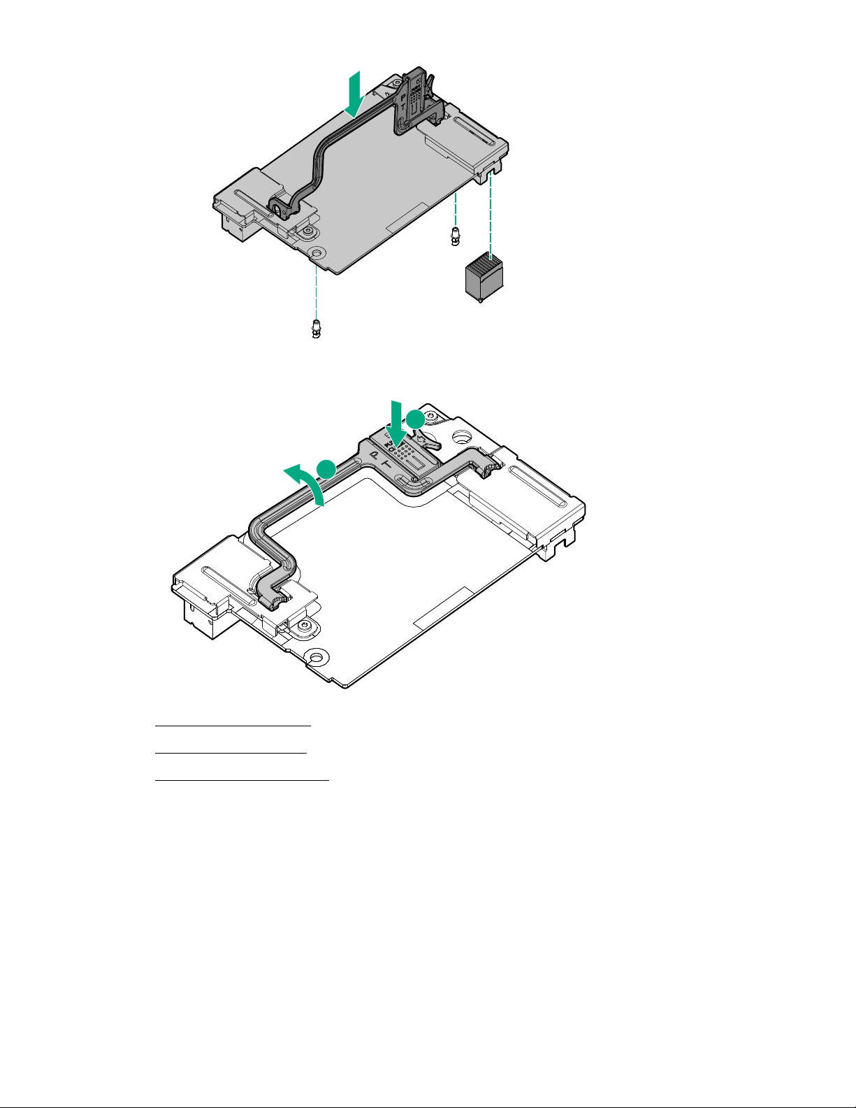
7. Install the M.2 SSDs on the M.2 riser board.
See Installing the M.2 SSDs on page 59.
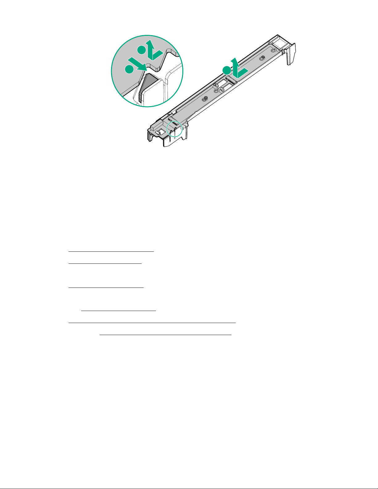
8. Align and install the M.2 riser board on the left DIMM baffle.
IMPORTANT: Be sure that the M.2 riser board aligns with the 7 guides and the triangular notch
on the left DIMM baffle.
Hardware options installation 57
9. Install the M.2 interposer board on the left DIMM baffle.
1
2
3
IMPORTANT: MLB is printed on the M.2 interposer board to indicate edge of the board that
connects to the system board. When the M.2 interposer board is installed, MLB must face out
towards the edge of the server blade.
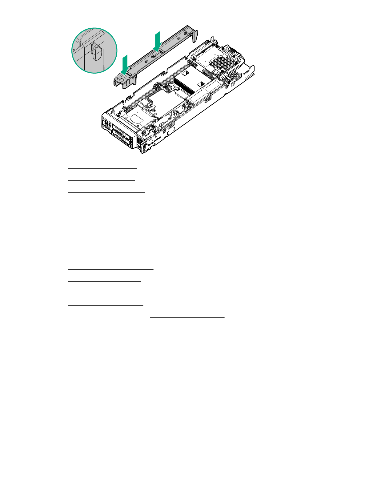
10. Align and install the left DIMM baffle in the server blade.
IMPORTANT: When installing each DIMM baffle, be sure that the alignment tabs engage with
the side of the server blade.
58 Hardware options installation
11. Install the access panel on page 23.
12. Install the server blade on page 42.
13. Power up the server blade on page 21.
Installing the M.2 SSDs
Prerequisites
A No. 1 Phillips screwdriver is required to perform this procedure.
Procedure
1. Power down the server blade on page 21.
2. Remove the server blade on page 22.
3. Place the server blade on a flat, level work surface.
4. Remove the access panel on page 22.
5. Remove the left DIMM baffle (Remove the DIMM baffles on page 23).
6. Verify that the PEM nuts and rubber stoppers are in the correct location to support the length of the
M.2 SSDs being installed. Relocate the PEM nuts and rubber stoppers, if necessary.
For more information, see Relocate the PEM nut and rubber stopper on page 28.
7. Remove the screw with a No. 1 Phillips screwdriver, and then install the M.2 SSD.
Hardware options installation 59

1
2
3
8. If necessary, repeat the M.2 SSD installation procedure for a second drive.
9. Install the left DIMM baffle (Install the DIMM baffles on page 25).
10. Install the access panel on page 23.
11. Install the server blade on page 42.
12. Power up the server blade on page 21.
Memory options
IMPORTANT: This server blade does not support mixing LRDIMMs and RDIMMs. Attempting to mix
any combination of these DIMMs can cause the server to halt during BIOS initialization. All memory
installed in the server blade must be of the same type.
DIMM and NVDIMM population information
For specific DIMM and NVDIMM population information, see the DIMM population guidelines on the
Hewlett Packard Enterprise website (http://www.hpe.com/docs/memory-population-rules).
DIMM-processor compatibility
The installed processor determines the type of DIMM that is supported in the server blade:
• First-generation Intel Xeon Scalable processors support DDR4-2666 DIMMs.
• Second-generation Intel Xeon Scalable processors support DDR4-2933 DIMMs.
Mixing DIMM types is not supported. Install only the supported DDR4-2666 or DDR4-2933 DIMMs in the
server blade.
HPE SmartMemory speed information
For more information about memory speed information, see the Hewlett Packard Enterprise website
(https://www.hpe.com/docs/memory-speed-table).
Installing a DIMM
The server supports up to 16 DIMMs.
60 Hardware options installation

Prerequisites
Before installing this option, be sure that you have the following the components included with the
hardware option kit.
For more information on specific options, see the server blade QuickSpecs on the Hewlett Packard
Enterprise website (http://www.hpe.com/info/qs).
Procedure
1. Power down the server blade on page 21.
2. Remove the server blade on page 22.
3. Place the server blade on a flat, level work surface.
4. Remove the access panel on page 22.
IMPORTANT: When removing a DIMM baffle, do not remove the following options when
installed on the DIMM baffle:
• M.2 enablement option (left DIMM baffle)
• HPE Smart Storage Battery (right DIMM baffle)
5. Remove the DIMM baffles on page 23.
6. Open the appropriate DIMM slot latches.
7. Install the DIMM.
8. Install the DIMM baffles on page 25.
9. Install the access panel on page 23.
10. Install the server blade on page 42.
11. Power up the server blade on page 21.
To configure the memory mode, use the BIOS/Platform Configuration (RBSU) in the UEFI System
Utilities.
Hardware options installation 61
HPE 16GB NVDIMM option
HPE NVDIMMs are flash-backed NVDIMMs used as fast storage and are designed to eliminate smaller
storage bottlenecks. The HPE 16GB NVDIMM for HPE ProLiant Gen10 servers is ideal for smaller
database storage bottlenecks, write caching tiers, and any workload constrained by storage bottlenecks.
The HPE 16GB NVDIMM is supported on select HPE ProLiant Gen10 servers with first generation Intel
Xeon Scalable processors. The server blade can support up to 12 NVDIMMs in 2 socket servers (up to
192GB) and up to 24 NVDIMMs in 4 socket servers (up to 384GB). The HPE Smart Storage Battery
provides backup power to the memory slots allowing data to be moved from the DRAM portion of the
NVDIMM to the Flash portion for persistence during a power down event.
For more information on HPE NVDIMMs, see the Hewlett Packard Enterprise website (http://
www.hpe.com/info/persistentmemory).
NVDIMM-processor compatibility
HPE 16GB NVDIMMs are only supported in servers with first generation Intel Xeon Scalable processors
installed.
Server requirements for NVDIMM support
Before installing an HPE 16GB NVDIMM in a server blade, make sure that the following components and
software are available:
• A supported HPE server using Intel Xeon Scalable Processors: For more information, see the
NVDIMM QuickSpecs on the Hewlett Packard Enterprise website (
http://www.hpe.com/info/qs).
• An HPE Smart Storage Battery
• A minimum of one regular DIMM: The system cannot have only NVDIMM-Ns installed.
• A supported operating system with persistent memory/NVDIMM drivers. For the latest software
information, see the Hewlett Packard Enterprise website (http://persistentmemory.hpe.com).
• For minimum firmware versions, see the HPE 16GB NVDIMM User Guide on the Hewlett Packard
Enterprise website (http://www.hpe.com/info/nvdimm-docs).
To determine NVDIMM support for your server blade, see the server blade QuickSpecs on the Hewlett
Packard Enterprise website (http://www.hpe.com/info/qs).
Installing an NVDIMM
CAUTION: To avoid damage to the hard drives, memory, and other system components, the air
baffle, drive blanks, and access panel must be installed when the server is powered up.
CAUTION: To avoid damage to the hard drives, memory, and other system components, be sure to
install the correct DIMM baffles for your server model.
CAUTION: DIMMs are keyed for proper alignment. Align notches in the DIMM with the
corresponding notches in the DIMM slot before inserting the DIMM. Do not force the DIMM into the
slot. When installed properly, not all DIMMs will face in the same direction.
CAUTION: Electrostatic discharge can damage electronic components. Be sure you are properly
grounded before beginning this procedure.
62 Hardware options installation

CAUTION: Failure to properly handle DIMMs can cause damage to DIMM components and the
1
2
2
system board connector.
CAUTION: Unlike traditional storage devices, NVDIMMs are fully integrated in with the ProLiant
server blade. Data loss can occur when system components, such as the processor or HPE Smart
Storage Battery, fails. HPE Smart Storage battery is a critical component required to perform the
backup functionality of NVDIMMs. It is important to act when HPE Smart Storage Battery related
failures occur. Always follow best practices for ensuring data protection.
Prerequisites
Before installing an NVDIMM, be sure the server blade meets the Server requirements for NVDIMM
support on page 62.
Procedure
1. Power down the server blade on page 21.
2. Remove the server blade on page 22.
3. Place the server blade on a flat, level work surface.
4. Remove the access panel on page 22.
IMPORTANT: When removing a DIMM baffle, do not remove the following options when
installed on the DIMM baffle:
• M.2 enablement option (left DIMM baffle)
• HPE Smart Storage Battery (right DIMM baffle)
5. Remove the DIMM baffles on page 23.
6. Locate any NVDIMMs already installed in the server blade.
7. Verify that all LEDs on any installed NVDIMMs are off.
8. Install the NVDIMM.
9. Install and connect the HPE Smart Storage Battery, if it is not already installed (HPE Smart Storage
Battery option).
Hardware options installation 63

10. Install any components removed to access the DIMM slots and the HPE Smart Storage Battery.
11. Install the access panel on page 23.
12. Install the server blade on page 42.
13. Power up the server blade on page 21.
14. If required, sanitize the NVDIMM-Ns. For more information, see NVDIMM sanitization on page 64.
Configuring the server blade for NVDIMMs
After installing NVDIMMs, configure the server blade for NVDIMMs. For information on configuring
settings for NVDIMMs, see the HPE 16GB NVDIMM User Guide on the Hewlett Packard Enterprise
website (
The server blade can be configured for NVDIMMs using either of the following:
• UEFI System Utilities—Use System Utilities through the Remote Console to configure the server blade
• iLO RESTful API for HPE iLO 5—For more information about configuring the system for NVDIMMs,
http://www.hpe.com/info/nvdimm-docs).
for NVDIMM memory options by pressing the F9 key during POST. For more information about UEFI
System Utilities, see the Hewlett Packard Enterprise website (http://www.hpe.com/info/uefi/docs).
see https://hewlettpackard.github.io/ilo-rest-api-docs/ilo5/.
Saving system default settings as user default settings
After configuring the NVDIMM settings for the server blade, Hewlett Packard Enterprise recommends
saving the settings as the user default settings. To save the settings, do the following:
Procedure
1. From the System Utilities screen, select System Configuration —> BIOS/Platform Configuration
(RBSU) —> System Default Options —> User Default Options, and press the Enter key.
2. Select Save User Defaults, and press the Enter key.
3. Select Yes, Save to save the current settings as the system default settings, and then press the Enter
key.
4. Press the F10 key to save the changes.
For more information about changing the settings, see the UEFI System Utilities User Guide for your
server blade on the Hewlett Packard Enterprise website (http://www.hpe.com/info/UEFI/docs).
NVDIMM sanitization
Media sanitization is defined by NIST SP800-88 Guidelines for Media Sanitization (Rev 1, Dec 2014) as
"a general term referring to the actions taken to render data written on media unrecoverable by both
ordinary and extraordinary means."
The specification defines the following levels:
64 Hardware options installation

• Clear: Overwrite user-addressable storage space using standard write commands; might not sanitize
data in areas not currently user-addressable (such as bad blocks and overprovisioned areas)
• Purge: Overwrite or erase all storage space that might have been used to store data using dedicated
device sanitize commands, such that data retrieval is "infeasible using state-of-the-art laboratory
techniques"
• Destroy: Ensure that data retrieval is "infeasible using state-of-the-art laboratory techniques" and
render the media unable to store data (such as disintegrate, pulverize, melt, incinerate, or shred)
The NVDIMM-N Sanitize options are intended to meet the Purge level.
For more information on sanitization for NVDIMMs, see the following sections in the HPE 16GB NVDIMM
User Guide on the Hewlett Packard Enterprise website (http://www.hpe.com/info/nvdimm-docs):
• NVDIMM sanitization policies
• NVDIMM sanitization guidelines
• Setting the NVDIMM-N Sanitize/Erase on the Next Reboot Policy
NIST SP800-88 Guidelines for Media Sanitization (Rev 1, Dec 2014) is available for download from the
NIST website (http://nvlpubs.nist.gov/nistpubs/SpecialPublications/NIST.SP.800-88r1.pdf).
NVDIMM relocation guidelines
Requirements for relocating NVDIMMs or a set of NVDIMMs when the data must be preserved
• The destination server blade hardware must match the original server blade hardware configuration.
• All System Utilities settings in the destination server blade must match the original System Utilities
settings in the original server blade.
• If NVDIMM-Ns are used with NVDIMM Interleaving ON mode in the original server blade, do the
following:
◦ Install the NVDIMMs in the same DIMM slots in the destination server blade.
◦ Install the entire NVDIMM set (all the NVDIMM-Ns on the processor) on the destination server
blade.
This guideline would apply when replacing a system board due to system failure.
If any of the requirements cannot be met during NVDIMM relocation, do the following:
◦ Manually back up the NVDIMM-N data before relocating NVDIMM-Ns to another server blade.
◦ Relocate the NVDIMM-Ns to another server blade.
◦ Sanitize all NVDIMM-Ns on the new server blade before using them.
Requirements for relocating NVDIMMs or a set of NVDIMMs when the data does not have to be
preserved
If data on the NVDIMM-N or set of NVDIMM-Ns does not have to be preserved, then
• Move the NVDIMM-Ns to the new location and sanitize all NVDIMM-Ns after installing them to the new
location. For more information, see NVDIMM sanitization on page 64.
• Observe all DIMM and NVDIMM population guidelines. For more information, see DIMM and NVDIMM
population information on page 60.
Hardware options installation 65
• Observe the process for removing an NVDIMM.
• Observe the process for installing an NVDIMM.
• Review and configure the system settings for NVDIMMs. For more information, see Configuring the
server blade for NVDIMMs on page 64.
Installing the processor-heatsink assembly
Intelligent System Tuning supports specific processors and configurations. For more information, see the
product QuickSpecs on the Hewlett Packard Enterprise website (http://www.hpe.com/info/qs).
IMPORTANT: Existing HPE ProLiant and HPE Synergy Gen10 server products containing firstgeneration Intel Xeon Scalable processors may not be upgraded to second-generation Intel Xeon
Scalable processors at this time. For more information, see the product QuickSpecs on the Hewlett
Packard Enterprise website (http://www.hpe.com/info/qs).
Prerequisites
Before installing the processor-heatsink assembly, be sure to have the following:
• The processor-heatsink assembly kit contents
• T-30 Torx screwdriver
Procedure
1. Observe the following alerts:
WARNING: To reduce the risk of personal injury from hot surfaces, allow the drives and the
internal system components to cool before touching them.
CAUTION: When handling the heatsink, always hold it along the top and bottom of the fins.
Holding it from the sides can damage the fins.
CAUTION: To avoid damage to the processor or system board, only authorized personnel
should attempt to replace or install the processor in this server blade.
CAUTION: To prevent possible server blade malfunction and damage to the equipment,
multiprocessor configurations must contain processors with the same part number.
CAUTION: If installing a processor with a faster speed, update the system ROM before
installing the processor.
To download firmware and view installation instructions, see the Hewlett Packard Enterprise
Support Center website.
CAUTION: THE CONTACTS ARE VERY FRAGILE AND EASILY DAMAGED. To avoid
damage to the socket or processor, do not touch the contacts.
2. Update the system ROM.
Locate and download the latest ROM version from the Hewlett Packard Enterprise website at http://
www.hpe.com/support. Follow the instructions on the website to update the system ROM.
66 Hardware options installation

3. Power down the server blade on page 21.
4. Remove the server blade on page 22.
5. Remove the access panel on page 22.
6. Remove the DIMM baffles on page 23.
7. Remove the heatsink blank. Retain the heatsink blank for future use.
8. Install the processor-heatsink assembly:
a. Locate the Pin 1 indicator on the processor frame and the socket.
b. Align the processor heatsink assembly with the alignment pins and gently lower it down until it sits
evenly on the socket. The heatsink alignment pins are keyed. The processor will only install one
way.
A standard heatsink is shown. Your heatsink might look different.
Hardware options installation 67

9. Using a T-30 Torx screwdriver, fully tighten each heatsink nut in the order indicated on the heatsink
Front of Server
T30, 12 in-lbs
1
3
24
1 12 2
3 34 4
Must Install Must Remove
Rear
Fully tighten
until screws
will not turn
Start
here
1 3
4 2
label (1 > 2 > 3 > 4) until it no longer turns.
10. Install the DIMM baffles on page 25.
11. Install the access panel on page 23.
12. Install the server blade on page 42.
13. Power up the server blade on page 21
HPE Trusted Platform Module 2.0 Gen10 option
Overview
Use these instructions to install and enable an HPE TPM 2.0 Gen10 Kit in a supported server blade. This
option is not supported on Gen9 and earlier server blades.
This procedure includes three sections:
1. Installing the Trusted Platform Module board.
2. Enabling the Trusted Platform Module.
3. Retaining the recovery key/password.
HPE TPM 2.0 installation is supported with specific operating system support such as Microsoft
Windows Server® 2012 R2 and later. For more information about operating system support, see the
product QuickSpecs on the Hewlett Packard Enterprise website (http://www.hpe.com/info/qs). For more
information about Microsoft® Windows® BitLocker Drive Encryption feature, see the Microsoft website
(http://www.microsoft.com).
CAUTION: If the TPM is removed from the original server blade and powered up on a different
server blade, data stored in the TPM including keys will be erased.
®
68 Hardware options installation

IMPORTANT: In UEFI Boot Mode, the HPE TPM 2.0 Gen10 Kit can be configured to operate as
TPM 2.0 (default) or TPM 1.2 on a supported server blade. In Legacy Boot Mode, the configuration
can be changed between TPM 1.2 and TPM 2.0, but only TPM 1.2 operation is supported.
TPM 2.0 location
The TPM 2.0 is located on the system board near the front of the server blade.
HPE Trusted Platform Module 2.0 Guidelines
CAUTION: Always observe the guidelines in this document. Failure to follow these guidelines can
cause hardware damage or halt data access.
Hewlett Packard Enterprise SPECIAL REMINDER: Before enabling TPM functionality on this system,
you must ensure that your intended use of TPM complies with relevant local laws, regulations and
policies, and approvals or licenses must be obtained if applicable.
For any compliance issues arising from your operation/usage of TPM which violates the above mentioned
requirement, you shall bear all the liabilities wholly and solely. Hewlett Packard Enterprise will not be
responsible for any related liabilities.
When installing or replacing a TPM, observe the following guidelines:
• Do not remove an installed TPM. Once installed, the TPM becomes a permanent part of the system
board.
• When installing or replacing hardware, Hewlett Packard Enterprise service providers cannot enable
the TPM or the encryption technology. For security reasons, only the customer can enable these
features.
• When returning a system board for service replacement, do not remove the TPM from the system
board. When requested, Hewlett Packard Enterprise Service provides a TPM with the spare system
board.
Hardware options installation 69
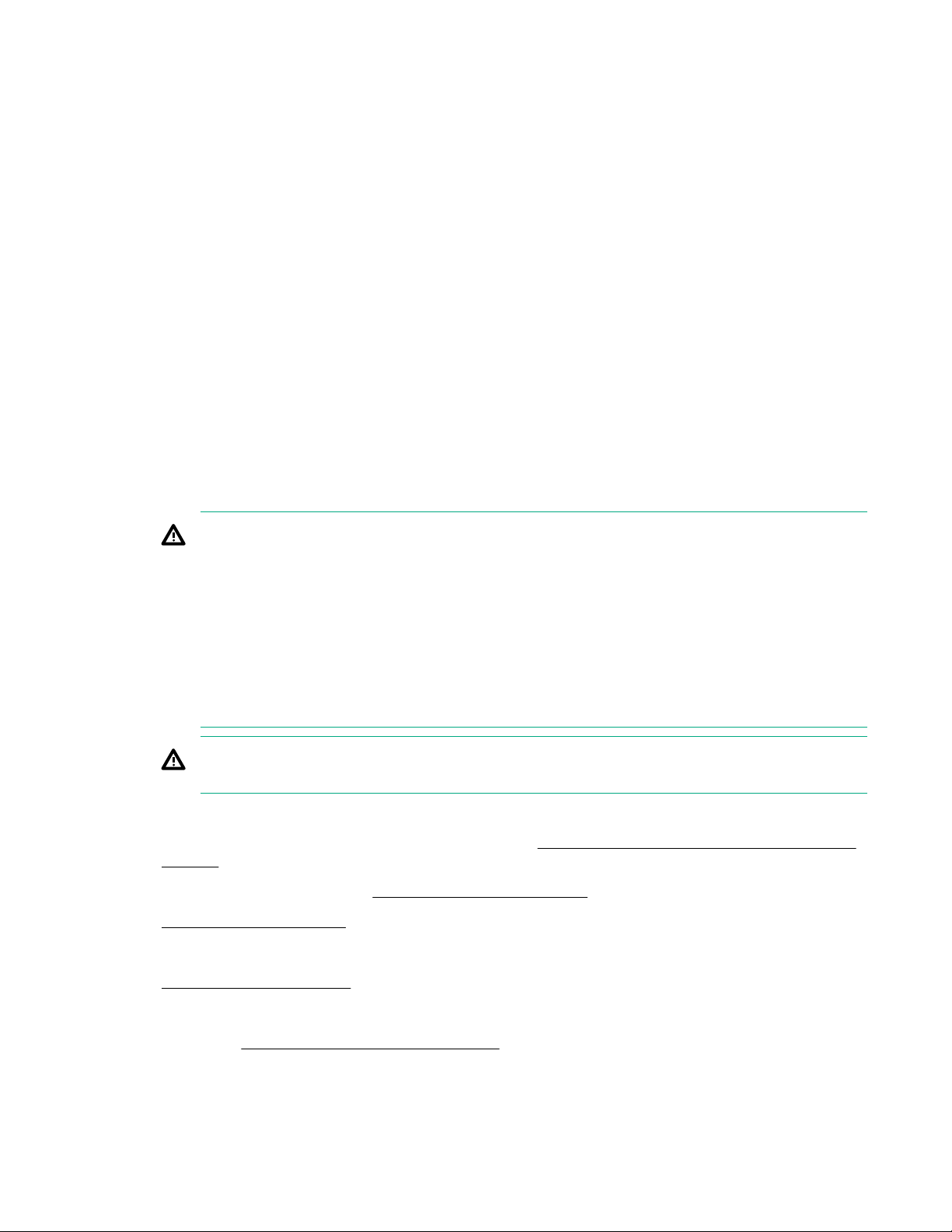
• Any attempt to remove the cover of an installed TPM from the system board can damage the TPM
cover, the TPM, and the system board.
• If the TPM is removed from the original server and powered up on a different server, data stored in the
TPM including keys will be erased.
• When using BitLocker, always retain the recovery key/password. The recovery key/password is
required to complete Recovery Mode after BitLocker detects a possible compromise of system
integrity.
• Hewlett Packard Enterprise is not liable for blocked data access caused by improper TPM use. For
operating instructions, see the TPM documentation or the encryption technology feature
documentation provided by the operating system.
Installing and enabling the HPE TPM 2.0 Gen10 Kit
Installing the Trusted Platform Module board
Preparing the server blade for installation
Procedure
1. Observe the following warnings:
WARNING: The front panel Power On/Standby button does not shut off system power. Portions
of the power supply and some internal circuitry remain active until AC power is removed.
To reduce the risk of personal injury, electric shock, or damage to the equipment, remove power
from the server blade:
For rack and tower servers, remove the power cord.
For server blades and compute modules, remove the server blade or compute module from the
enclosure.
WARNING: To reduce the risk of personal injury from hot surfaces, allow the drives and the
internal system components to cool before touching them.
2. Update the system ROM.
Locate and download the latest ROM version from the Hewlett Packard Enterprise Support Center
website. Follow the instructions on the website to update the system ROM.
3. Power down the server blade (Power down the server blade on page 21).
4. Remove the server blade on page 22.
5. Place the server blade on a flat, level work surface.
6. Remove the access panel on page 22.
7. Remove any options or cables that may prevent access to the TPM connector.
8. Proceed to Installing the TPM board and cover on page 71.
70 Hardware options installation

Installing the TPM board and cover
1
2
Procedure
1. Observe the following alerts:
CAUTION: If the TPM is removed from the original server blade and powered up on a different
server blade, data stored in the TPM including keys will be erased.
CAUTION: The TPM is keyed to install only in the orientation shown. Any attempt to install the
TPM in a different orientation might result in damage to the TPM or system board.
2. Align the TPM board with the key on the connector, and then install the TPM board. To seat the board,
press the TPM board firmly into the connector. To locate the TPM connector on the system board, see
the server blade label on the access panel.
3. Install the TPM cover:
a. Line up the tabs on the cover with the openings on either side of the TPM connector.
b. To snap the cover into place, firmly press straight down on the middle of the cover.
Hardware options installation 71

4. Proceed to Preparing the server blade for operation on page 72.
Preparing the server blade for operation
Procedure
1. Install any options or cables previously removed to access the TPM connector.
2. Install the access panel on page 23.
3. Install the server blade on page 42.
4. Power up the server blade on page 21.
Enabling the Trusted Platform Module
When enabling the Trusted Platform module, observe the following guidelines:
• By default, the Trusted Platform Module is enabled as TPM 2.0 when the server blade is powered on
after installing it.
• In UEFI Boot Mode, the Trusted Platform Module can be configured to operate as TPM 2.0 or TPM
1.2.
• In Legacy Boot Mode, the Trusted Platform Module configuration can be changed between TPM 1.2
and TPM 2.0, but only TPM 1.2 operation is supported.
Enabling the Trusted Platform Module as TPM 2.0
Procedure
1. During the server blade startup sequence, press the F9 key to access System Utilities.
2. From the System Utilities screen, select System Configuration > BIOS/Platform Configuration
(RBSU) > Server Security > Trusted Platform Module options.
3. Verify the following:
72 Hardware options installation

• "Current TPM Type" is set to TPM 2.0.
• "Current TPM State" is set to Present and Enabled.
• "TPM Visibility" is set to Visible.
4. If changes were made in the previous step, press the F10 key to save your selection.
5. If F10 was pressed in the previous step, do one of the following:
• If in graphical mode, click Yes.
• If in text mode, press the Y key.
6. Press the ESC key to exit System Utilities.
7. If changes were made and saved, the server blade prompts for reboot request. Press the Enter key to
confirm reboot.
If the following actions were performed, the server blade reboots a second time without user input.
During this reboot, the TPM setting becomes effective.
• Changing from TPM 1.2 and TPM 2.0
• Changing TPM bus from FIFO to CRB
• Enabling or disabling TPM
• Clearing the TPM
8. Enable TPM functionality in the OS, such as Microsoft Windows BitLocker or measured boot.
For more information, see the Microsoft website.
Enabling the Trusted Platform Module as TPM 1.2
Procedure
1. During the server blade startup sequence, press the F9 key to access System Utilities.
2. From the System Utilities screen select System Configuration > BIOS/Platform Configuration
(RBSU) > Server Security > Trusted Platform Module options.
3. Change the "TPM Mode Switch Operation" to TPM 1.2.
4. Verify "TPM Visibility" is Visible.
5. Press the F10 key to save your selection.
6. When prompted to save the change in System Utilities, do one of the following:
• If in graphical mode, click Yes.
• If in text mode, press the Y key.
7. Press the ESC key to exit System Utilities.
The server blade reboots a second time without user input. During this reboot, the TPM setting
becomes effective.
8. Enable TPM functionality in the OS, such as Microsoft Windows BitLocker or measured boot.
Hardware options installation 73

For more information, see the Microsoft website.
Retaining the recovery key/password
The recovery key/password is generated during BitLocker setup, and can be saved and printed after
BitLocker is enabled. When using BitLocker, always retain the recovery key/password. The recovery key/
password is required to enter Recovery Mode after BitLocker detects a possible compromise of system
integrity.
To help ensure maximum security, observe the following guidelines when retaining the recovery key/
password:
• Always store the recovery key/password in multiple locations.
• Always store copies of the recovery key/password away from the server blade.
• Do not save the recovery key/password on the encrypted hard drive.
74 Hardware options installation
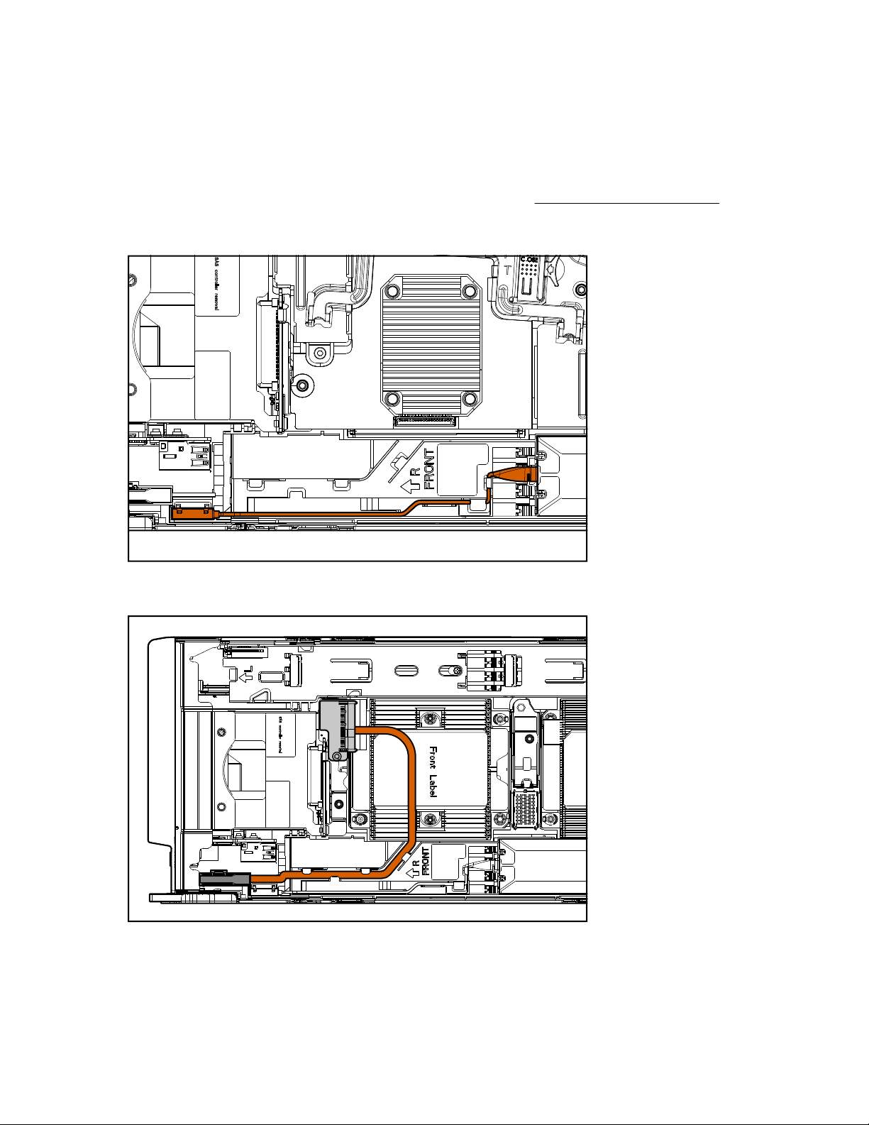
Cabling
Cabling resources
Cabling configurations and requirements vary depending on the product and installed options. For more
information about product features, specifications, options, configurations, and compatibility, see the
product QuickSpecs on the Hewlett Packard Enterprise website (
HPE Smart Storage Battery cabling
http://www.hpe.com/info/qs).
Direct connect SATA cabling
Cabling 75
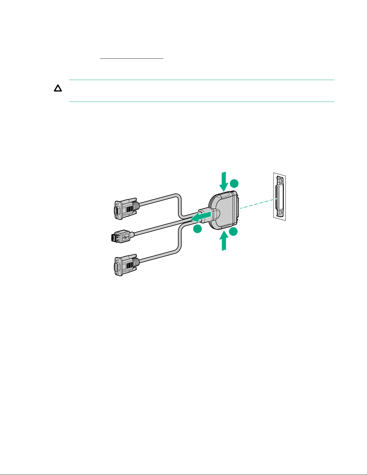
Using the HPE c-Class Blade SUV Cable
1
2
1
The c-Class Blade SUV Cable enables the user to perform server blade administration, configuration, and
diagnostic procedures by connecting video and USB devices directly to the server blade. For SUV cable
connectors, see "SUV cable connectors."
Disconnecting and replacing the SUV cable
CAUTION: Before disconnecting the SUV cable from the connector, always squeeze the release
buttons on the sides of the connector. Failure to do so can result in damage to the equipment.
Procedure
1. Disconnect the SUV cable from the server blade.
a. Press and hold both sides of the connector.
b. Disconnect the cable from the server blade.
To replace the component, reverse the removal procedure.
Connecting locally to a server blade with video and USB devices
Use the SUV cable to connect a monitor and any of the following USB devices:
• USB hub
• USB keyboard
• USB mouse
• USB CD/DVD-ROM drive
The USB connectors on the SUV cable do not support devices that require greater than a 500mA power
source.
76 Cabling

Numerous configurations are possible. This section offers two possible configurations. For more
information, see USB support on page 89.
Accessing a server blade with local KVM
Prerequisites
For this configuration, a USB hub is not necessary. To connect additional devices, use a USB hub.
CAUTION: Before disconnecting the SUV cable from the connector, always squeeze the release
buttons on the sides of the connector. Failure to do so can result in damage to the equipment.
Procedure
1. Open the serial label pull tab and connect the c-Class Blade SUV Cable to the server blade.
2. Connect the video connector to a monitor.
3. Connect a USB mouse to one USB connector.
4. Connect a USB keyboard to the second USB connector.
Item Description
1 Monitor
2 USB mouse
3 USB keyboard
4 c-Class Blade SUV Cable
Accessing local media devices
Prerequisites
Use the following configuration when configuring a server blade or loading software updates and patches
from a USB CD/DVD-ROM.
Use a USB hub when connecting a USB CD-ROM drive to the server blade. The USB connectors on the
SUV cable do not support devices that require a power source greater than 500mA. The USB hub
Cabling 77
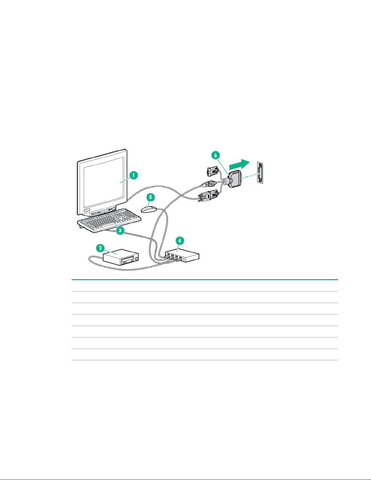
provides additional connections and the power required to support USB keys or external drives that
require more than 500mA at 5V.
Procedure
1. Open the serial label pull tab and connect the c-Class Blade SUV cable to the server blade.
2. Connect the video connector to a monitor.
3. Connect a USB hub to one USB connector.
4. Connect the following to the USB hub:
• USB CD/DVD-ROM drive
• USB keyboard
• USB mouse
78 Cabling
Item Description
1 Monitor
2 USB CD/DVD-ROM drive
3 USB keyboard
4 USB hub
5 USB mouse
6 c-Class Blade SUV Cable

Troubleshooting
Troubleshooting resources
Troubleshooting resources are available for HPE Gen10 server products in the following documents:
• Troubleshooting Guide for HPE ProLiant Gen10 servers provides procedures for resolving common
problems and comprehensive courses of action for fault isolation and identification, issue resolution,
and software maintenance.
• Error Message Guide for HPE ProLiant Gen10 servers and HPE Synergy provides a list of error
messages and information to assist with interpreting and resolving error messages.
• Integrated Management Log Messages and Troubleshooting Guide for HPE ProLiant Gen10 and HPE
Synergy provides IML messages and associated troubleshooting information to resolve critical and
cautionary IML events.
To access the troubleshooting resources, see the Hewlett Packard Enterprise Information Library (
www.hpe.com/info/gen10-troubleshooting).
http://
Troubleshooting 79

Software and configuration utilities
Server mode
The software and configuration utilities presented in this section operate in online mode, offline mode, or
in both modes.
Software or configuration utility Server mode
Active Health System on page 81 Online and Offline
HPE iLO 5 on page 81 Online and Offline
HPE Smart Storage Administrator on page 88 Online and Offline
iLO RESTful API on page 83 Online and Offline
Intelligent Provisioning on page 84 Online and Offline
Scripting Toolkit for Windows and Linux on
page 85
Service Pack for ProLiant on page 90 Online and Offline
Smart Update Manager on page 90 Online and Offline
UEFI System Utilities on page 86 Offline
Product QuickSpecs
For more information about product features, specifications, options, configurations, and compatibility, see
the product QuickSpecs on the Hewlett Packard Enterprise website (http://www.hpe.com/info/qs).
Active Health System Viewer
Active Health System Viewer (AHSV) is an online tool used to read, diagnose, and resolve server issues
quickly using AHS uploaded data. AHSV provides Hewlett Packard Enterprise recommended repair
actions based on experience and best practices. AHSV provides the ability to:
• Read server configuration information
• View Driver/Firmware inventory
Online
• Review Event Logs
• Respond to Fault Detection Analytics alerts
• Open new and update existing support cases
80 Software and configuration utilities

Active Health System
The Active Health System monitors and records changes in the server hardware and system
configuration.
The Active Health System provides:
• Continuous health monitoring of over 1600 system parameters
• Logging of all configuration changes
• Consolidated health and service alerts with precise time stamps
• Agentless monitoring that does not affect application performance
For more information about the Active Health System, see the iLO user guide at the following website:
http://www.hpe.com/support/ilo-docs.
Active Health System data collection
The Active Health System does not collect information about your operations, finances, customers,
employees, or partners.
Examples of information that is collected:
• Server model and serial number
• Processor model and speed
• Storage capacity and speed
• Memory capacity and speed
• Firmware/BIOS and driver versions and settings
The Active Health System does not parse or change OS data from third-party error event log activities (for
example, content created or passed through the OS).
Active Health System Log
The data collected by the Active Health System is stored in the Active Health System Log. The data is
logged securely, isolated from the operating system, and separate from customer data. Host resources
are not consumed in the collection and logging of Active Health System data.
When the Active Health System Log is full, new data overwrites the oldest data in the log.
It takes less than 5 minutes to download the Active Health System Log and send it to a support
professional to help you resolve an issue.
When you download and send Active Health System data to Hewlett Packard Enterprise, you agree to
have the data used for analysis, technical resolution, and quality improvements. The data that is collected
is managed according to the privacy statement, available at http://www.hpe.com/info/privacy.
You can also upload the log to the Active Health System Viewer. For more information, see the Active
Health System Viewer documentation at the following website: http://www.hpe.com/support/ahsv-docs.
HPE iLO 5
iLO 5 is a remote server management processor embedded on the system boards of HPE ProLiant
servers and Synergy compute modules. iLO enables the monitoring and controlling of servers from
remote locations. iLO management is a powerful tool that provides multiple ways to configure, update,
monitor, and repair servers remotely. iLO (Standard) comes preconfigured on Hewlett Packard Enterprise
servers without an additional cost or license.
Software and configuration utilities 81

Features that enhance server administrator productivity and additional new security features are licensed.
For more information, see the iLO licensing guide at the following website: http://www.hpe.com/support/
ilo-docs.
For more information about iLO, see the iLO user guide at the following website: http://www.hpe.com/
support/ilo-docs.
iLO Federation
iLO Federation enables you to manage multiple servers from one system using the iLO web interface.
When configured for iLO Federation, iLO uses multicast discovery and peer-to-peer communication to
enable communication between the systems in iLO Federation groups.
When you navigate to one of the iLO Federation pages, a data request is sent from the iLO system
running the web interface to its peers, and from those peers to other peers until all data for the selected
iLO Federation group is retrieved.
iLO supports the following features:
• Group health status—View server health and model information.
• Group Virtual Media—Connect URL-based media for access by a group of servers.
• Group power control—Manage the power status of a group of servers.
• Group power capping—Set dynamic power caps for a group of servers.
• Group firmware update—Update the firmware of a group of servers.
• Group license installation—Enter a license key to activate iLO licensed features on a group of servers.
• Group configuration—Add iLO Federation group memberships for multiple iLO systems.
Any user can view information on iLO Federation pages, but a license is required for using the following
features: Group Virtual Media, Group power control, Group power capping, Group configuration, and
Group firmware update.
For more information about iLO Federation, see the iLO user guide at the following website:
www.hpe.com/support/ilo-docs.
iLO Service Port
The Service Port is a USB port with the label iLO on supported ProLiant Gen10 servers and Synergy
Gen10 compute modules.
To find out if your server model supports this feature, see the server specifications document at the
following website: http://www.hpe.com/info/qs.
When you have physical access to a server, you can use the Service Port to do the following:
• Download the Active Health System Log to a supported USB flash drive.
When you use this feature, the connected USB flash drive is not accessible by the host operating
system.
http://
• Connect a client (such as a laptop) with a supported USB to Ethernet adapter to access the iLO web
interface, remote console, CLI, iLO RESTful API, or scripts.
Hewlett Packard Enterprise recommends the HPE USB to Ethernet Adapter (part number Q7Y55A).
Some servers, such as the XL170r, require an adapter to connect a USB to Ethernet adapter to the
iLO Service Port.
82 Software and configuration utilities

Hewlett Packard Enterprise recommends the HPE Micro USB to USB Adapter (part number 789904B21).
When you use the iLO Service Port:
• Actions are logged in the iLO Event Log.
• The server UID flashes to indicate the Service Port status.
You can also retrieve the Service Port status by using a REST client and the iLO RESTful API.
• You cannot use the Service Port to boot any device within the server, or the server itself.
• You cannot access the server by connecting to the Service Port.
• You cannot access the connected device from the server.
For more information about the iLO Service Port, see the iLO user guide at the following website: http://
www.hpe.com/support/ilo-docs.
iLO RESTful API
iLO includes the iLO RESTful API, which is Redfish API conformant. The iLO RESTful API is a
management interface that server management tools can use to perform configuration, inventory, and
monitoring tasks by sending basic HTTPS operations (GET, PUT, POST, DELETE, and PATCH) to the
iLO web server.
To learn more about the iLO RESTful API, see the Hewlett Packard Enterprise website (http://
www.hpe.com/support/restfulinterface/docs).
For specific information about automating tasks using the iLO RESTful API, see libraries and sample
code at http://www.hpe.com/info/redfish.
For more information, watch the Redfish & How it works with HPE Server Management video.
RESTful Interface Tool
The RESTful Interface Tool (iLOREST) is a scripting tool that allows you to automate HPE server
management tasks. It provides a set of simplified commands that take advantage of the iLO RESTful API.
You can install the tool on your computer for remote use or install it locally on a server with a Windows or
Linux Operating System. The RESTful Interface Tool offers an interactive mode, a scriptable mode, and a
file-based mode similar to CONREP to help decrease automation times.
For more information, see the following website: http://www.hpe.com/info/resttool.
iLO Amplifier Pack
The iLO Amplifier Pack is an advanced server inventory, firmware and driver update solution that enables
rapid discovery, detailed inventory reporting, firmware, and driver updates by leveraging iLO advanced
functionality. The iLO Amplifier Pack performs rapid server discovery and inventory for thousands of
supported servers for the purpose of updating firmware and drivers at scale.
For more information about iLO Amplifier Pack, see the iLO Amplifier Pack User Guide at the following
website: http://www.hpe.com/support/ilo-ap-ug-en.
Integrated Management Log
The IML records hundreds of events and stores them in an easy-to-view form. The IML timestamps each
event with one-minute granularity.
You can view recorded events in the IML in several ways, including the following:
Software and configuration utilities 83

• From within HPE SIM
• From within the UEFI System Utilities
• From within the Embedded UEFI shell
• From within the iLO web interface
Intelligent Provisioning
Intelligent Provisioning is a single-server deployment tool embedded in ProLiant servers and HPE
Synergy compute modules. Intelligent Provisioning simplifies server setup, providing a reliable and
consistent way to deploy servers.
Intelligent Provisioning 3.30 and later includes HPE SMB Setup. When you launch F10 mode from the
POST screen, you are prompted to select whether you want to enter the Intelligent Provisioning or HPE
SMB Setup mode.
NOTE: After you have selected a mode, you must reprovision the server to change the mode that
launches when you boot to F10.
Intelligent Provisioning prepares the system for installing original, licensed vendor media and Hewlett
Packard Enterprise-branded versions of OS software. Intelligent Provisioning also prepares the system to
integrate optimized server support software from the Service Pack for ProLiant (SPP). SPP is a
comprehensive systems software and firmware solution for ProLiant servers, server blades, their
enclosures, and HPE Synergy compute modules. These components are preloaded with a basic set of
firmware and OS components that are installed along with Intelligent Provisioning.
IMPORTANT: HPE ProLiant XL servers do not support operating system installation with Intelligent
Provisioning, but they do support the maintenance features. For more information, see "Performing
Maintenance" in the Intelligent Provisioning user guide and online help.
After the server is running, you can update the firmware to install additional components. You can also
update any components that have been outdated since the server was manufactured.
To access Intelligent Provisioning:
• Press F10 from the POST screen and enter either Intelligent Provisioning or HPE SMB Setup.
• From the iLO web interface using Always On. Always On allows you to access Intelligent
Provisioning without rebooting your server.
Intelligent Provisioning operation
Intelligent Provisioning includes the following components:
• Critical boot drivers
• Active Health System (AHS)
• Erase Utility
• Deployment Settings
84 Software and configuration utilities

IMPORTANT:
• Although your server is preloaded with firmware and drivers, Hewlett Packard Enterprise
recommends updating the firmware upon initial setup. Also, downloading and updating the latest
version of Intelligent Provisioning ensures the latest supported features are available.
• For ProLiant servers, firmware is updated using the Intelligent Provisioning Firmware Update
utility.
• Do not update firmware if the version you are currently running is required for compatibility.
NOTE: Intelligent Provisioning does not function within multihomed configurations. A multihomed host is
one that is connected to two or more networks or has two or more IP addresses.
Intelligent Provisioning provides installation help for the following operating systems:
• Microsoft Windows Server
• Red Hat Enterprise Linux
• SUSE Linux Enterprise Server
• VMware ESXi/vSphere Custom Image
• ClearOS
Not all versions of an OS are supported. For information about specific versions of a supported operating
system, see the OS Support Matrix on the Hewlett Packard Enterprise website (http://www.hpe.com/
info/ossupport).
Management Security
HPE ProLiant Gen10 servers are built with some of the industry's most advanced security capabilities, out
of the box, with a foundation of secure embedded management applications and firmware. The
management security provided by HPE embedded management products enables secure support of
modern workloads, protecting your components from unauthorized access and unapproved use. The
range of embedded management and optional software and firmware available with the iLO Advanced
and iLO Advanced Premium Security Edition licenses provides security features that help ensure
protection, detection, and recovery from advanced cyber-attacks. For more information, see the HPE
Gen10 Server Security Reference Guide on the Hewlett Packard Enterprise Information Library at http://
www.hpe.com/support/gen10-security-ref-en.
For information about the iLO Advanced Premium Security Edition license, see http://www.hpe.com/
servers/ilopremium.
Scripting Toolkit for Windows and Linux
The STK for Windows and Linux is a server deployment product that delivers an unattended automated
installation for high-volume server deployments. The STK is designed to support ProLiant servers. The
toolkit includes a modular set of utilities and important documentation that describes how to apply these
tools to build an automated server deployment process.
The STK provides a flexible way to create standard server configuration scripts. These scripts are used to
automate many of the manual steps in the server configuration process. This automated server
configuration process cuts time from each deployment, making it possible to scale rapid, high-volume
server deployments.
For more information or to download the STK, see the Hewlett Packard Enterprise website.
Software and configuration utilities 85

UEFI System Utilities
The UEFI System Utilities is embedded in the system ROM. Its features enable you to perform a wide
range of configuration activities, including:
• Configuring system devices and installed options.
• Enabling and disabling system features.
• Displaying system information.
• Selecting the primary boot controller or partition.
• Configuring memory options.
• Launching other preboot environments.
HPE servers with UEFI can provide:
• Support for boot partitions larger than 2.2 TB. Such configurations could previously only be used for
boot drives when using RAID solutions.
• Secure Boot that enables the system firmware, option card firmware, operating systems, and software
collaborate to enhance platform security.
• UEFI Graphical User Interface (GUI)
• An Embedded UEFI Shell that provides a preboot environment for running scripts and tools.
• Boot support for option cards that only support a UEFI option ROM.
Selecting the boot mode
This server provides two Boot Mode configurations: UEFI Mode and Legacy BIOS Mode. Certain boot
options require that you select a specific boot mode. By default, the boot mode is set to UEFI Mode. The
system must boot in UEFI Mode to use certain options, including:
• Secure Boot, UEFI Optimized Boot, Generic USB Boot, IPv6 PXE Boot, iSCSI Boot, and Boot from
URL
• Fibre Channel/FCoE Scan Policy
NOTE: The boot mode you use must match the operating system installation. If not, changing the boot
mode can impact the ability of the server to boot to the installed operating system.
Prerequisite
When booting to UEFI Mode, leave UEFI Optimized Boot enabled.
Procedure
1. From the System Utilities screen, select System Configuration > BIOS/Platform Configuration
(RBSU) > Boot Options > Boot Mode.
2. Select a setting.
86 Software and configuration utilities

• UEFI Mode (default)—Configures the system to boot to a UEFI compatible operating system.
• Legacy BIOS Mode—Configures the system to boot to a traditional operating system in Legacy
BIOS compatibility mode.
3. Save your setting.
4. Reboot the server.
Secure Boot
Secure Boot is a server security feature that is implemented in the BIOS and does not require special
hardware. Secure Boot ensures that each component launched during the boot process is digitally signed
and that the signature is validated against a set of trusted certificates embedded in the UEFI BIOS.
Secure Boot validates the software identity of the following components in the boot process:
• UEFI drivers loaded from PCIe cards
• UEFI drivers loaded from mass storage devices
• Preboot UEFI Shell applications
• OS UEFI boot loaders
When Secure Boot is enabled:
• Firmware components and operating systems with boot loaders must have an appropriate digital
signature to execute during the boot process.
• Operating systems must support Secure Boot and have an EFI boot loader signed with one of the
authorized keys to boot. For more information about supported operating systems, see http://
www.hpe.com/servers/ossupport.
You can customize the certificates embedded in the UEFI BIOS by adding or removing your own
certificates, either from a management console directly attached to the server, or by remotely connecting
to the server using the iLO Remote Console.
You can configure Secure Boot:
• Using the System Utilities options described in the following sections.
• Using the iLO RESTful API to clear and restore certificates. For more information, see the Hewlett
Packard Enterprise website (http://www.hpe.com/info/redfish).
• Using the secboot command in the Embedded UEFI Shell to display Secure Boot databases, keys,
and security reports.
Launching the Embedded UEFI Shell
Use the Embedded UEFI Shell option to launch the Embedded UEFI Shell. The Embedded UEFI Shell is
a preboot command-line environment for scripting and running UEFI applications, including UEFI boot
loaders. The Shell also provides CLI-based commands you can use to obtain system information, and to
configure and update the system BIOS.
Software and configuration utilities 87

Prerequisites
Embedded UEFI Shell is set to Enabled.
Procedure
1. From the System Utilities screen, select Embedded Applications > Embedded UEFI Shell.
The Embedded UEFI Shell screen appears.
2. Press any key to acknowledge that you are physically present.
This step ensures that certain features, such as disabling Secure Boot or managing the Secure Boot
certificates using third-party UEFI tools, are not restricted.
3. If an administrator password is set, enter it at the prompt and press Enter.
The Shell> prompt appears.
4. Enter the commands required to complete your task.
5. Enter the exit command to exit the Shell.
HPE Smart Storage Administrator
HPE SSA is the main tool for configuring arrays on HPE Smart Array SR controllers. It exists in three
interface formats: the HPE SSA GUI, the HPE SSA CLI, and HPE SSA Scripting. All formats provide
support for configuration tasks. Some of the advanced tasks are available in only one format.
The diagnostic features in HPE SSA are also available in the standalone software HPE Smart Storage
Administrator Diagnostics Utility CLI.
During the initial provisioning of the server or compute module, an array is required to be configured
before the operating system can be installed. You can configure the array using SSA.
HPE SSA is accessible both offline (either through HPE Intelligent Provisioning or as a standalone
bootable ISO image) and online:
• Accessing HPE SSA in the offline environment
IMPORTANT: If you are updating an existing server blade in an offline environment, obtain the
latest version of HPE SSA through Service Pack for ProLiant before performing configuration
procedures.
Using one of multiple methods, you can run HPE SSA before launching the host operating system. In
offline mode, users can configure or maintain detected and supported devices, such as optional Smart
Array controllers and integrated Smart Array controllers. Some HPE SSA features are only available in
the offline environment, such as setting the boot controller and boot volume.
• Accessing HPE SSA in the online environment
This method requires an administrator to download the HPE SSA executables and install them. You
can run HPE SSA online after launching the host operating system.
For more information, see HPE Smart Array SR Gen10 Configuration Guide at the Hewlett Packard
Enterprise website.
HPE InfoSight for servers
The HPE InfoSight portal is a secure web interface hosted by HPE that allows you to monitor supported
devices through a graphical interface.
88 Software and configuration utilities

HPE InfoSight for servers:
• Combines the machine learning and predictive analytics of HPE InfoSight with the health and
performance monitoring of Active Health System (AHS) and HPE iLO to optimize performance and
predict and prevent problems
• Provides automatic collection and analysis of the sensor and telemetry data from AHS to derive
insights from the behaviors of the install base to provide recommendations to resolve problems and
improve performance
For more information on getting started and using HPE InfoSight for servers, go to: http://www.hpe.com/
info/infosight-servers-docs.
USB support
Hewlett Packard Enterprise Gen10 server blades support all USB operating speeds depending on the
device that is connected to the server blade.
External USB functionality
Hewlett Packard Enterprise provides external USB support to enable local connection of USB devices for
server blade administration, configuration, and diagnostic procedures.
For additional security, external USB functionality can be disabled through USB options in UEFI System
Utilities.
Redundant ROM support
The server blade enables you to upgrade or configure the ROM safely with redundant ROM support. The
server blade has a single ROM that acts as two separate ROM images. In the standard implementation,
one side of the ROM contains the current ROM program version, while the other side of the ROM
contains a backup version.
NOTE: The server blade ships with the same version programmed on each side of the ROM.
Safety and security benefits
When you flash the system ROM, the flashing mechanism writes over the backup ROM and saves the
current ROM as a backup, enabling you to switch easily to the alternate ROM version if the new ROM
becomes corrupted for any reason. This feature protects the existing ROM version, even if you
experience a power failure while flashing the ROM.
Keeping the system current
Updating firmware or system ROM
To update firmware or system ROM, use one of the following methods:
• The Firmware Update option in the System Utilities.
• The fwupdate command in the Embedded UEFI Shell.
• Service Pack for ProLiant (SPP)
• HPE online flash components
• Moonshot Component Pack
Software and configuration utilities 89

More information
Updating firmware from the System Utilities on page 91
Service Pack for ProLiant
SPP is a systems software and firmware solution delivered as a single ISO file download. This solution
uses SUM as the deployment tool and is tested and supports HPE ProLiant, HPE BladeSystem, HPE
Synergy, and HPE Apollo servers and infrastructure.
SPP, along with SUM and iSUT, provides Smart Update system maintenance tools that systematically
update HPE ProLiant, HPE BladeSystem, HPE Synergy, and HPE Apollo servers and infrastructure.
SPP can be used in an online mode on a server running Windows, Linux, or VMware vSphere ESXi, or in
an offline mode where the server is booted to an operating system included in the ISO file.
The preferred method for downloading an SPP is using the SPP Custom Download at https://
www.hpe.com/servers/spp/custom.
The SPP is also available for download from the SPP download page at https://www.hpe.com/
servers/spp/download.
Smart Update Manager
SUM is an innovative tool for maintaining and updating the firmware, drivers, and system software of HPE
ProLiant, HPE BladeSystem, HPE Synergy, and HPE Apollo servers, infrastructure, and associated
options.
SUM identifies associated nodes you can update at the same time to avoid interdependency issues.
Key features of SUM include:
• Discovery engine that finds installed versions of hardware, firmware, and software on nodes.
• SUM deploys updates in the correct order and ensures that all dependencies are met before deploying
an update.
• Interdependency checking.
• Automatic and step-by-step Localhost Guided Update process.
• Web browser-based user interface.
• Ability to create custom baselines and ISOs.
• Support for iLO Repository (Gen10 iLO 5 nodes only).
• Simultaneous firmware and software deployment for multiple remote nodes.
• Local offline firmware deployments with SPP deliverables.
• Extensive logging in all modes.
NOTE: SUM does not support third-party controllers, including flashing hard drives behind the controllers.
Smart Update Tools
Smart Update Tools is a software utility used with iLO 4, HPE OneView, Service Pack for ProLiant (SPP),
and Smart Update Manager (SUM) to stage, install, and activate firmware and driver updates.
NOTE: HPE OneView manages the iLO while iSUT runs on each server and deploys the updates. The
same tool might not manage both applications. Create a process that notifies the administrators when
updates are available.
90 Software and configuration utilities

• Smart Update Tools: Polls iLO to check for requests from HPE OneView for updates through the
management network and orchestrates staging, deploying, and activating updates. You can adjust the
polling interval by issuing the appropriate command-line option provided by iSUT. Performs inventory
on target servers, stages deployment, deploys updates, and then reboots the servers.
• HPE OneView: Displays available updates for servers. Communicates with iSUT (or SUT 1.x) to
initiate updates, reports the status on the Firmware section of the Server Profile page of HPE
OneView. HPE OneView provides automated compliance reporting in the dashboard.
• SPP: A comprehensive systems software and firmware update solution, which is delivered as a single
ISO image.
• SUM: A tool for firmware and driver maintenance for HPE ProLiant servers and associated options.
NOTE: Do not manage the same nodes with SUM and HPE OneView at the same time.
Updating firmware from the System Utilities
Use the Firmware Updates option to update firmware components in the system, including the system
BIOS, NICs, and storage cards.
Procedure
1. Access the System ROM Flash Binary component for your server from the Hewlett Packard Enterprise
Support Center.
2. Copy the binary file to a USB media or iLO virtual media.
3. Attach the media to the server.
4. Launch the System Utilities, and select Embedded Applications > Firmware Update.
5. Select a device.
The Firmware Updates screen lists details about your selected device, including the current firmware
version in use.
6. Select Select Firmware File.
7. Select the flash file in the File Explorer list.
The firmware file is loaded and the Firmware Updates screen lists details of the file in the Selected
firmware file field.
8. Select Image Description, and then select a firmware image.
A device can have multiple firmware images.
9. Select Start firmware update.
Updating the firmware from the UEFI Embedded Shell
Procedure
1. Access the System ROM Flash Binary component for your server from the Hewlett Packard Enterprise
Support Center (http://www.hpe.com/support/hpesc).
2. Copy the binary file to a USB media or iLO virtual media.
3. Attach the media to the server.
Software and configuration utilities 91

4. Boot to the UEFI Embedded Shell.
5. To obtain the assigned file system volume for the USB key, enter map –r.
6. Change to the file system that contains the System ROM Flash Binary component for your server.
Enter one of the fsx file systems available, such as fs0: or fs1:, and press Enter.
7. Use the cd command to change from the current directory to the directory that contains the binary file.
8. Flash the system ROM by entering fwupdate –d BIOS -f filename.
9. Reboot the server. A reboot is required after the firmware update in order for the updates to take effect
and for hardware stability to be maintained.
Online Flash components
This component provides updated system firmware that can be installed directly on supported operating
systems. Additionally, when used in conjunction with SUM, this Smart Component allows the user to
update firmware on remote servers from a central location. This remote deployment capability eliminates
the need for the user to be physically present at the server to perform a firmware update.
Drivers
IMPORTANT: Always perform a backup before installing or updating device drivers.
Update drivers using any of the following Smart Update Solutions:
• Download the latest Service Pack for ProLiant (includes Smart Update Manager)
• Create a custom SPP download
• Download Smart Update Manager for Linux
• Download specific drivers
To locate the drivers for a server, go to the Hewlett Packard Enterprise Support Center website,
and then search for the product name/number.
Software and firmware
Update software and firmware before using the server blade for the first time, unless any installed
software or components require an older version.
For system software and firmware updates, use one of the following sources:
• Download the SPP from the Hewlett Packard Enterprise website (http://www.hpe.com/servers/spp/
download).
• Download individual drivers, firmware, or other system software components from the server blade
product page in the Hewlett Packard Enterprise Support Center website (http://www.hpe.com/
support/hpesc).
Operating system version support
For information about specific versions of a supported operating system, refer to the operating system
support matrix.
92 Software and configuration utilities

HPE Pointnext Portfolio
HPE Pointnext delivers confidence, reduces risk, and helps customers realize agility and stability. Hewlett
Packard Enterprise helps customers succeed through Hybrid IT by simplifying and enriching the onpremise experience, informed by public cloud qualities and attributes.
Operational Support Services enable you to choose the right service level, length of coverage, and
response time to fit your business needs. For more information, see the Hewlett Packard Enterprise
website:
https://www.hpe.com/us/en/services/operational.html
Utilize the Advisory and Transformation Services in the following areas:
• Private or hybrid cloud computing
• Big data and mobility requirements
• Improving data center infrastructure
• Better use of server, storage, and networking technology
For more information, see the Hewlett Packard Enterprise website:
http://www.hpe.com/services/consulting
Proactive notifications
30 to 60 days in advance, Hewlett Packard Enterprise sends notifications to subscribed customers on
upcoming:
• Hardware, firmware, and software changes
• Bulletins
• Patches
• Security alerts
You can subscribe to proactive notifications on the Hewlett Packard Enterprise website.
Software and configuration utilities 93

Removing and replacing the system battery
If the server blade no longer automatically displays the correct date and time, then replace the battery
that provides power to the real-time clock. Under normal use, battery life is 5 to 10 years.
WARNING: The computer contains an internal lithium manganese dioxide, a vanadium pentoxide,
or an alkaline battery pack. A risk of fire and burns exists if the battery pack is not properly handled.
To reduce the risk of personal injury:
• Do not attempt to recharge the battery.
• Do not expose the battery to temperatures higher than 60°C (140°F).
• Do not disassemble, crush, puncture, short external contacts, or dispose of in fire or water.
• Replace only with the spare designated for this product.
Procedure
1. Power down the server blade on page 21.
2. Remove the server blade on page 22.
3. Place the server blade on a flat, level work surface.
4. Remove the access panel on page 22.
5. Identify the battery location.
For more information on battery location, see System board components on page 13.
6. Remove the left DIMM baffle (DIMM baffle (left side)).
7. Remove the battery.
IMPORTANT: Replacing the system board battery resets the system ROM to its default
configuration. After replacing the battery, reconfigure the system through UEFI System Utilities.
94 Removing and replacing the system battery

To replace the component, reverse the removal procedure.
For more information about battery replacement or proper disposal, contact an authorized reseller or an
authorized service provider.
Removing and replacing the system battery 95

Electrostatic discharge
Preventing electrostatic discharge
To prevent damaging the system, be aware of the precautions you must follow when setting up the
system or handling parts. A discharge of static electricity from a finger or other conductor may damage
system boards or other static-sensitive devices. This type of damage may reduce the life expectancy of
the device.
Procedure
• Avoid hand contact by transporting and storing products in static-safe containers.
• Keep electrostatic-sensitive parts in their containers until they arrive at static-free workstations.
• Place parts on a grounded surface before removing them from their containers.
• Avoid touching pins, leads, or circuitry.
• Always be properly grounded when touching a static-sensitive component or assembly.
Grounding methods to prevent electrostatic discharge
Several methods are used for grounding. Use one or more of the following methods when handling or
installing electrostatic-sensitive parts:
• Use a wrist strap connected by a ground cord to a grounded workstation or computer chassis. Wrist
straps are flexible straps with a minimum of 1 megohm ±10 percent resistance in the ground cords. To
provide proper ground, wear the strap snug against the skin.
• Use heel straps, toe straps, or boot straps at standing workstations. Wear the straps on both feet
when standing on conductive floors or dissipating floor mats.
• Use conductive field service tools.
• Use a portable field service kit with a folding static-dissipating work mat.
If you do not have any of the suggested equipment for proper grounding, have an authorized reseller
install the part.
For more information on static electricity or assistance with product installation, contact the Hewlett
Packard Enterprise Support Center.
96 Electrostatic discharge

Specifications
Environmental specifications
Specification Value
Temperature range
Operating 10°C to 35°C (50°F to 95°F)
Nonoperating -30°C to 60°C (-22°F to 140°F)
Relative humidity (noncondensing)
Operating 10% to 90% @ 28°C (82.4°F)
Nonoperating 5% to 95% @ 38.7°C (101.7°F)
Altitude
Operating 3,050 m (10,000 ft)
Nonoperating 9,144 m (30,000 ft)
1
The following temperature conditions and limitations apply:
• All temperature ratings shown are for sea level.
3
1
2
—
—
—
• An altitude derating of 1°C per 304.8 m (1.8°F per 1,000 ft) up to 3,048 m (10,000 ft) applies.
• No direct sunlight is allowed.
• The maximum permissible rate of change is 10°C/hr (18°F/hr).
• The type and number of options installed might reduce the upper temperature and humidity limits.
• Operating with a fan fault or above 30°C (86°F) might reduce system performance.
2
Storage maximum humidity of 95% is based on a maximum temperature of 45°C (113°F).
3
Maximum storage altitude corresponds to a minimum pressure of 70 kPa (10.1 psia).
Server blade specifications
Specification Value
Height 180.70 mm (7.11 in)
Depth 517.51mm (20.37 in)
Width 55.37 mm (2.18 in)
Weight (maximum) 6.33 kg (13.96 lb)
Weight (minimum) 4.50 kg (9.90 lb)
Specifications 97

Websites
General websites
Hewlett Packard Enterprise Information Library
www.hpe.com/info/EIL
Single Point of Connectivity Knowledge (SPOCK) Storage compatibility matrix
www.hpe.com/storage/spock
Storage white papers and analyst reports
www.hpe.com/storage/whitepapers
For additional websites, see Support and other resources.
98 Websites

Support and other resources
Accessing Hewlett Packard Enterprise Support
• For live assistance, go to the Contact Hewlett Packard Enterprise Worldwide website:
http://www.hpe.com/info/assistance
• To access documentation and support services, go to the Hewlett Packard Enterprise Support Center
website:
http://www.hpe.com/support/hpesc
Information to collect
• Technical support registration number (if applicable)
• Product name, model or version, and serial number
• Operating system name and version
• Firmware version
• Error messages
• Product-specific reports and logs
• Add-on products or components
• Third-party products or components
Accessing updates
• Some software products provide a mechanism for accessing software updates through the product
interface. Review your product documentation to identify the recommended software update method.
• To download product updates:
Hewlett Packard Enterprise Support Center
www.hpe.com/support/hpesc
Hewlett Packard Enterprise Support Center: Software downloads
www.hpe.com/support/downloads
Software Depot
www.hpe.com/support/softwaredepot
• To subscribe to eNewsletters and alerts:
www.hpe.com/support/e-updates
• To view and update your entitlements, and to link your contracts and warranties with your profile, go to
the Hewlett Packard Enterprise Support Center More Information on Access to Support Materials
page:
www.hpe.com/support/AccessToSupportMaterials
Support and other resources 99

IMPORTANT: Access to some updates might require product entitlement when accessed through
the Hewlett Packard Enterprise Support Center. You must have an HPE Passport set up with
relevant entitlements.
Customer self repair
Hewlett Packard Enterprise customer self repair (CSR) programs allow you to repair your product. If a
CSR part needs to be replaced, it will be shipped directly to you so that you can install it at your
convenience. Some parts do not qualify for CSR. Your Hewlett Packard Enterprise authorized service
provider will determine whether a repair can be accomplished by CSR.
For more information about CSR, contact your local service provider or go to the CSR website:
http://www.hpe.com/support/selfrepair
Remote support
Remote support is available with supported devices as part of your warranty or contractual support
agreement. It provides intelligent event diagnosis, and automatic, secure submission of hardware event
notifications to Hewlett Packard Enterprise, which will initiate a fast and accurate resolution based on your
product's service level. Hewlett Packard Enterprise strongly recommends that you register your device for
remote support.
If your product includes additional remote support details, use search to locate that information.
Remote support and Proactive Care information
HPE Get Connected
www.hpe.com/services/getconnected
HPE Proactive Care services
www.hpe.com/services/proactivecare
HPE Proactive Care service: Supported products list
www.hpe.com/services/proactivecaresupportedproducts
HPE Proactive Care advanced service: Supported products list
www.hpe.com/services/proactivecareadvancedsupportedproducts
Proactive Care customer information
Proactive Care central
www.hpe.com/services/proactivecarecentral
Proactive Care service activation
www.hpe.com/services/proactivecarecentralgetstarted
Warranty information
To view the warranty information for your product, see the links provided below:
HPE ProLiant and IA-32 Servers and Options
www.hpe.com/support/ProLiantServers-Warranties
HPE Enterprise and Cloudline Servers
www.hpe.com/support/EnterpriseServers-Warranties
HPE Storage Products
www.hpe.com/support/Storage-Warranties
HPE Networking Products
www.hpe.com/support/Networking-Warranties
100 Support and other resources
 Loading...