

Page 1

HPE 3100 48 v2 Switch
Layer 3—IP Services
Configuration Guide
Part number: 5998-7643R
Software version: Release 2111
Document version: 6W100-20160122
Page 2

© Copyright 2016 Hewlett Packard Enterprise Development LP
The information contained herein is subject to change without notice. The only warranties for Hewlett Packard
Enterprise products and services are set forth in the express warranty statements acco mpanying such
products and services. Nothing herein should be construe d as constituting an additional warranty. Hewlett
Packard Enterprise shall not be liable for technical or editorial errors or omissions co ntained herein.
Confidential computer software. V alid license from Hewlett Packard Enterprise required for possession, use, or
copying. Consistent with FAR 12.211 and 12.212, Commercial Computer Software, Computer Software
Documentation, and T e chnical Data for Commercial Items are licensed to the U.S. Government under vendor’s
standard commercial license.
Links to third-party websites take you outside the Hewlett Packard Enterprise website. Hewlett Packard
Enterprise has no control over and is not responsible for information outside the Hewlett Packard Enterprise
website.
Acknowledgments
Intel®, Itanium®, Pentium®, Intel Inside®, and the Intel Inside logo are trademarks of Intel Corporation in the
United States and other countries.
Microsoft® and Windows® are trademarks of the Microsoft group of companies.
Adobe® and Acrobat® are trademarks of Adobe Systems In corporated.
Java and Oracle are registered trademarks of Oracle and/or its affiliates.
UNIX® is a registered trademark of The Open Group.
Page 3

Contents
Configuring ARP ·············································································· 1
Overview ·································································································································· 1
ARP message format ··········································································································· 1
ARP operation ···················································································································· 1
ARP table ·························································································································· 2
Configuring a static ARP entry ······································································································ 3
Configuring the maximum number of dynamic ARP entries for an interface ············································ 3
Setting the aging timer for dynamic ARP entries ··············································································· 4
Enabling dynamic ARP entry check ······························································································· 4
Configuring ARP quick update ······································································································ 5
Configuring multicast ARP ··········································································································· 5
Displaying and maintaining ARP ··································································································· 6
ARP configuration examples ········································································································ 6
Static ARP entry configuration example···················································································· 6
Multicast ARP configuration example ······················································································· 7
Configuring gratuitous ARP ······························································ 10
Overview ································································································································ 10
Gratuitous ARP packet learning ···························································································· 10
Periodic sending of gratuitous ARP packets ············································································ 10
Configuration guidelines ············································································································ 10
Configuration procedure ············································································································ 11
Enabling IP conflict notification ···································································································· 11
Configuring proxy ARP ···································································· 12
Overview ································································································································ 12
Common proxy ARP ·········································································································· 12
Local proxy ARP ··············································································································· 12
Enabling common proxy ARP ····································································································· 13
Enabling local proxy ARP ·········································································································· 13
Displaying and maintaining proxy ARP ························································································· 13
Proxy ARP configuration examples ······························································································ 14
Common proxy ARP configuration example ············································································ 14
Local proxy ARP configuration example in case of port isolation ·················································· 15
Local proxy ARP configuration example in isolate-user-VLAN ····················································· 16
Configuring ARP snooping ······························································· 18
Overview ································································································································ 18
Configuration procedure ············································································································ 18
Displaying and maintaining ARP snooping ···················································································· 18
Configuring IP addressing ································································ 19
Overview ································································································································ 19
IP address classes ············································································································ 19
Special IP addresses ········································································································· 20
Subnetting and masking ····································································································· 20
Assigning an IP address to an interface ························································································ 20
Configuration guidelines ····································································································· 21
Configuration procedure ····································································································· 21
Configuration example ········································································································ 21
Configuring IP unnumbered ········································································································ 23
Overview ························································································································· 23
Configuration guidelines ····································································································· 23
Configuration prerequisites ·································································································· 23
Configuration procedure ····································································································· 23
Displaying and maintaining IP addressing ····················································································· 24
i
Page 4

DHCP overview ············································································· 25
DHCP address allocation ··········································································································· 25
Dynamic IP address allocation process ·················································································· 25
IP address lease extension ·································································································· 26
DHCP message format ············································································································· 26
DHCP options ························································································································· 27
Common DHCP options ······································································································ 28
Custom options ················································································································· 28
Protocols and standards ············································································································ 32
Configuring DHCP server ································································· 33
Overview ································································································································ 33
DHCP address pool ··········································································································· 33
IP address allocation sequence ···························································································· 34
DHCP server configuration task list ······························································································ 34
Configuring an address pool for the DHCP server ··········································································· 35
Configuration task list ········································································································· 35
Creating a DHCP address pool ···························································································· 35
Configuring address allocation mode for a common address pool ················································ 36
Configuring dynamic address allocation for an extended address pool ·········································· 38
Configuring a domain name suffix for the client ········································································ 38
Configuring DNS servers for the client ··················································································· 39
Configuring WINS servers and NetBIOS node type for the client ················································· 39
Configuring BIMS server information for the client ···································································· 39
Configuring gateways for the client ························································································ 40
Configuring Option 184 parameters for the client with voice service ············································· 40
Configuring the TFTP server and bootfile name for the client ······················································ 41
Specifying a server's IP address for the DHCP client································································· 41
Configuring self-defined DHCP options ·················································································· 42
Enabling DHCP ······················································································································· 42
Enabling the DHCP server on an interface ···················································································· 43
Configuration guidelines ····································································································· 43
Configuration procedure ····································································································· 43
Applying an extended address pool on an interface ········································································· 43
Configuring the DHCP server security functions ············································································· 44
Configuration prerequisites ·································································································· 44
Enabling unauthorized DHCP server detection ········································································ 44
Configuring IP address conflict detection ················································································ 44
Enabling client offline detection ··································································································· 45
Enabling handling of Option 82 ··································································································· 45
Configuration prerequisites ·································································································· 45
Enabling Option 82 handling ································································································ 46
Specifying the threshold for sending trap messages ········································································ 46
Configuration prerequisites ·································································································· 46
Configuration procedure ····································································································· 46
Setting the DSCP value for DHCP packets ···················································································· 46
Displaying and maintaining the DHCP server ················································································· 47
DHCP server configuration examples ··························································································· 47
Static IP address assignment configuration example ································································· 48
Dynamic IP address assignment configuration example ····························································· 49
Self-defined option configuration example··············································································· 50
Troubleshooting DHCP server configuration ·················································································· 51
Symptom ························································································································· 51
Analysis ·························································································································· 51
Solution ··························································································································· 51
Configuring DHCP relay agent ·························································· 53
Overview ································································································································ 53
Fundamentals ··················································································································· 53
DHCP relay agent support for Option 82 ················································································· 54
DHCP relay agent configuration task list ······················································································· 54
ii
Page 5

Enabling DHCP ······················································································································· 55
Enabling the DHCP relay agent on an interface ·············································································· 55
Correlating a DHCP server group with a relay agent interface ···························································· 55
Configuration guidelines ····································································································· 55
Configuration procedure ····································································································· 56
Configuring the DHCP relay agent security functions ······································································· 56
Configuring address check ·································································································· 56
Configuring periodic refresh of dynamic client entries ································································ 57
Enabling unauthorized DHCP server detection ········································································ 57
Enabling DHCP starvation attack protection ············································································ 58
Enabling offline detection ··········································································································· 58
Configuring the DHCP relay agent to release an IP address ······························································ 59
Configuring the DHCP relay agent to support Option 82 ··································································· 59
Configuration prerequisites ·································································································· 59
Configuration guidelines ····································································································· 59
Configuration procedure ····································································································· 60
Setting the DSCP value for DHCP packets ···················································································· 60
Displaying and maintaining the DHCP relay agent ·········································································· 61
DHCP relay agent configuration examples ···················································································· 61
DHCP relay agent configuration example ··············································································· 61
DHCP relay agent Option 82 support configuration example ······················································· 62
Troubleshooting DHCP relay agent configuration ············································································ 63
Symptom ························································································································· 63
Analysis ·························································································································· 63
Solution ··························································································································· 63
Configuring DHCP client ·································································· 64
Configuration restrictions ··········································································································· 64
Enabling the DHCP client on an interface ······················································································ 64
Setting the DSCP value for DHCP packets ···················································································· 64
Displaying and maintaining the DHCP client ·················································································· 65
DHCP client configuration example ······························································································ 65
Network requirements ········································································································ 65
Configuration procedure ····································································································· 65
Verifying the configuration ··································································································· 66
Configuring DHCP snooping ····························································· 68
DHCP snooping functions ·········································································································· 68
Ensuring that DHCP clients obtain IP addresses from authorized DHCP servers ····························· 68
Recording IP-to-MAC mappings of DHCP clients ····································································· 68
Application environment of trusted ports ······················································································· 69
Configuring a trusted port connected to a DHCP server ····························································· 69
Configuring trusted ports in a cascaded network ············································································· 69
DHCP snooping support for Option 82 ·························································································· 70
DHCP snooping configuration task list ·························································································· 71
Configuring DHCP snooping basic functions ·················································································· 71
Configuring DHCP snooping to support Option 82 ··········································································· 72
Configuring DHCP snooping entries backup ·················································································· 74
Enabling DHCP starvation attack protection ··················································································· 75
Enabling DHCP-REQUEST message attack protection ···································································· 75
Enabling MAC and port check ····································································································· 76
Configuring DHCP packet rate limit ······························································································ 76
Displaying and maintaining DHCP snooping ·················································································· 76
DHCP snooping configuration examples ······················································································· 77
DHCP snooping configuration example ·················································································· 77
DHCP snooping Option 82 support configuration example ························································· 78
Configuring BOOTP client ································································ 79
Overview ································································································································ 79
BOOTP application ············································································································ 79
Obtaining an IP address dynamically ····················································································· 79
Protocols and standards ····································································································· 79
iii
Page 6

Configuration restrictions ··········································································································· 79
Configuring an interface to dynamically obtain an IP address through BOOTP ······································ 79
Displaying and maintaining BOOTP client configuration ··································································· 80
BOOTP client configuration example ···························································································· 80
Network requirements ········································································································ 80
Configuration procedure ····································································································· 80
Configuring IPv4 DNS ····································································· 81
Overview ································································································································ 81
Static domain name resolution ····························································································· 81
Dynamic domain name resolution ························································································· 81
DNS proxy ······················································································································· 82
DNS spoofing ··················································································································· 83
Configuring the IPv4 DNS client ·································································································· 84
Configuring static domain name resolution ·············································································· 84
Configuring dynamic domain name resolution ·········································································· 84
Configuring the DNS proxy ········································································································· 85
Configuring DNS spoofing ·········································································································· 85
Setting the DSCP value for DNS packets ······················································································ 86
Specifying the source interface for DNS packets ············································································· 86
Displaying and maintaining IPv4 DNS ·························································································· 86
Static domain name resolution configuration example ······································································ 87
Network requirements ········································································································ 87
Configuration procedure ····································································································· 87
Dynamic domain name resolution configuration example ·································································· 88
Network requirements ········································································································ 88
Configuration procedure ····································································································· 88
Verifying the configuration ··································································································· 90
DNS proxy configuration example ································································································ 91
Network requirements ········································································································ 91
Configuration procedure ····································································································· 91
Verifying the configuration ··································································································· 92
Troubleshooting IPv4 DNS configuration ······················································································· 92
Symptom ························································································································· 92
Solution ··························································································································· 92
Basic IP forwarding on the device ······················································ 93
FIB table ································································································································ 93
Displaying FIB table entries ········································································································ 93
Configuring load sharing ·································································· 95
Configuration procedure ············································································································ 95
Load sharing configuration example ····························································································· 95
Network requirements ········································································································ 95
Configuration procedure ····································································································· 95
Verifying the configuration ··································································································· 97
Configuring IRDP ··········································································· 98
Overview ································································································································ 98
Background ······················································································································ 98
Working mechanism ·········································································································· 98
Concepts ························································································································· 99
Protocols and standards ····································································································· 99
Configuration procedure ············································································································ 99
IRDP configuration example ····································································································· 100
Network requirements ······································································································ 100
Configuration procedure ··································································································· 101
Verifying the configuration ································································································· 101
Optimizing IP performance ····························································· 102
Enabling receiving and forwarding of directed broadcasts to a directly connected network ····················· 102
Enabling receiving of directed broadcasts to a directly connected network ··································· 102
iv
Page 7

Enabling forwarding of directed broadcasts to a directly connected network ································· 102
Configuration example ······································································································ 103
Configuring TCP attributes ······································································································· 103
Configuring TCP path MTU discovery ·················································································· 103
Configuring the TCP send/receive buffer size ········································································ 104
Configuring TCP timers ···································································································· 104
Configuring ICMP to send error packets ······················································································ 105
Advantages of sending ICMP error packets ··········································································· 105
Disadvantages of sending ICMP error packets ······································································· 106
Configuration procedure ··································································································· 106
Displaying and maintaining IP performance optimization ································································ 106
Configuring UDP helper ································································· 108
Overview ······························································································································ 108
Configuration restrictions and guidelines ····················································································· 108
Configuration procedure ·········································································································· 108
Displaying and maintaining UDP helper ······················································································ 109
UDP helper configuration example ····························································································· 109
Network requirements ······································································································ 109
Configuration procedure ··································································································· 109
Configuring IPv6 basics ································································· 111
Overview ······························································································································ 111
IPv6 features ·················································································································· 111
IPv6 addresses ··············································································································· 112
IPv6 neighbor discovery protocol ························································································ 114
IPv6 path MTU discovery ·································································································· 117
IPv6 transition technologies ······························································································· 117
Protocols and standards ··································································································· 118
IPv6 basics configuration task list ······························································································ 118
Configuring basic IPv6 functions ······························································································· 119
Enabling IPv6 ················································································································· 119
Configuring an IPv6 global unicast address ··········································································· 119
Configuring an IPv6 link-local address ················································································· 121
Configure an IPv6 anycast address ····················································································· 122
Configuring IPv6 ND ··············································································································· 123
Configuring a static neighbor entry ······················································································ 123
Configuring the maximum number of neighbors dynamically learned ·········································· 123
Setting the age timer for ND entries in stale state ··································································· 124
Configuring parameters related to RA messages ···································································· 124
Configuring the maximum number of attempts to send an NS message for DAD ··························· 126
Configuring ND snooping ·································································································· 127
Enabling ND proxy ··········································································································· 128
Configuring path MTU discovery ······························································································· 130
Configuring a static path MTU for a specific IPv6 address ························································ 130
Configuring the aging time for dynamic path MTUs ································································· 130
Configuring IPv6 TCP properties ······························································································· 131
Configuring ICMPv6 packet sending ·························································································· 131
Configuring the maximum ICMPv6 error packets sent in an interval············································ 131
Enabling replying to multicast echo requests ········································································· 132
Enabling sending ICMPv6 time exceeded messages ······························································ 132
Enabling sending ICMPv6 destination unreachable messages ·················································· 132
Enabling sending ICMPv6 redirect messages ········································································ 133
Enabling a device to discard IPv6 packets that contain extension headers ········································· 133
Configuring multicast ND ········································································································· 134
Displaying and maintaining IPv6 basics configuration ···································································· 134
IPv6 basics configuration example ····························································································· 135
Network requirements ······································································································ 135
Configuration procedure ··································································································· 136
Verifying the configuration ································································································· 137
Troubleshooting IPv6 basics configuration ··················································································· 141
Symptom ······················································································································· 141
v
Page 8

Solution ························································································································· 141
DHCPv6 overview ········································································ 142
Hardware compatibility ············································································································ 142
Introduction to DHCPv6 ··········································································································· 142
DHCPv6 address/prefix assignment ··························································································· 142
Rapid assignment involving two messages ··········································································· 142
Assignment involving four messages ··················································································· 142
Address/prefix lease renewal ···································································································· 143
Configuring stateless DHCPv6 ·································································································· 144
Operation ······················································································································ 144
Protocols and standards ·········································································································· 145
Configuring DHCPv6 server ··························································· 146
Overview ······························································································································ 146
Concepts ······················································································································· 146
Prefix selection process ···································································································· 147
DHCPv6 server configuration task list ························································································· 147
Enabling the DHCPv6 server ···································································································· 147
Creating a prefix pool ·············································································································· 148
Configuring a DHCPv6 address pool ·························································································· 148
Configuration restrictions and guidelines ·············································································· 148
Configuration procedure ··································································································· 148
Applying the address pool to an interface ···················································································· 149
Setting the DSCP value for DHCPv6 packets ··············································································· 150
Displaying and maintaining the DHCPv6 server ············································································ 150
DHCPv6 server configuration example ······················································································· 150
Network requirements ······································································································ 150
Configuration considerations ······························································································ 151
Configuration procedure ··································································································· 151
Verifying the configuration ································································································· 152
Configuring DHCPv6 relay agent ····················································· 154
Overview ······························································································································ 154
DHCPv6 relay agent operation ··························································································· 154
Configuring the DHCPv6 relay agent ·························································································· 155
Configuration guidelines ··································································································· 155
Configuration procedure ··································································································· 155
Setting the DSCP value for DHCPv6 packets ··············································································· 156
Displaying and maintaining the DHCPv6 relay agent ····································································· 156
DHCPv6 relay agent configuration example ················································································· 156
Network requirements ······································································································ 156
Configuration procedure ··································································································· 157
Verifying the configuration ································································································· 157
Configuring DHCPv6 client ····························································· 159
Overview ······························································································································ 159
Configuration guidelines ·········································································································· 159
Configuring IPv6 address acquisition ·························································································· 159
Configuring stateless DHCPv6 ·································································································· 159
Setting the DSCP value for DHCPv6 packets ··············································································· 160
Displaying and maintaining the DHCPv6 client ············································································· 160
Stateless DHCPv6 configuration example ··················································································· 160
Network requirements ······································································································ 160
Configuration procedure ··································································································· 161
Verifying the configuration ································································································· 161
Configuring DHCPv6 snooping ························································ 163
Overview ······························································································································ 163
Ensuring that DHCPv6 clients obtain IPv6 addresses from authorized DHCPv6 servers ················· 163
Recording IP-to-MAC mappings of DHCPv6 clients ································································ 164
Enabling DHCPv6 snooping ····································································································· 164
vi
Page 9

Configuring a DHCPv6 snooping trusted port ··············································································· 164
Configuring the maximum number of DHCPv6 snooping entries an interface can learn ························· 165
Configuring DHCPv6 snooping to support Option 18 and Option 37 ·················································· 165
Displaying and maintaining DHCPv6 snooping ············································································· 166
DHCPv6 snooping configuration example ··················································································· 166
Network requirements ······································································································ 166
Configuration procedure ··································································································· 167
Verifying the configuration ································································································· 167
Configuring IPv6 DNS ··································································· 168
Overview ······························································································································ 168
Configuring the IPv6 DNS client ································································································ 168
Configuring static domain name resolution ············································································ 168
Configuring dynamic domain name resolution ········································································ 168
Setting the DSCP value for IPv6 DNS packets ············································································· 169
Displaying and maintaining IPv6 DNS ························································································ 169
Static domain name resolution configuration example ···································································· 170
Network requirements ······································································································ 170
Configuration procedure ··································································································· 170
Dynamic domain name resolution configuration example ································································ 171
Network requirements ······································································································ 171
Configuration procedure ··································································································· 171
Verifying the configuration ································································································· 174
Configuring tunneling ···································································· 176
Overview ······························································································································ 176
IPv6 over IPv4 tunneling ··································································································· 176
IPv4 over IPv4 tunneling ··································································································· 178
IPv4 over IPv6 tunneling ··································································································· 179
IPv6 over IPv6 tunneling ··································································································· 180
Protocols and standards ··································································································· 180
Tunneling configuration task list ································································································ 181
Configuring a tunnel interface ··································································································· 181
Configuration guidelines ··································································································· 181
Configuration procedure ··································································································· 181
Configuring an IPv6 manual tunnel ···························································································· 182
Configuration prerequisites ································································································ 182
Configuration guidelines ··································································································· 182
Configuration procedure ··································································································· 183
Configuration example ······································································································ 183
Configuring a 6to4 tunnel ········································································································· 187
Configuration prerequisites ································································································ 187
Configuration guidelines ··································································································· 187
Configuration procedure ··································································································· 187
Configuration example ······································································································ 188
Configuring an ISATAP tunnel ·································································································· 190
Configuration prerequisites ································································································ 190
Configuration guidelines ··································································································· 190
Configuration procedure ··································································································· 191
Configuration example ······································································································ 192
Configuring an IPv4 over IPv4 tunnel ························································································· 194
Configuration prerequisites ································································································ 194
Configuration guidelines ··································································································· 194
Configuration procedure ··································································································· 195
Configuration example ······································································································ 195
Configuring an IPv4 over IPv6 tunnel ························································································· 198
Configuration prerequisites ································································································ 198
Configuration guidelines ··································································································· 198
Configuration procedure ··································································································· 199
Configuration example ······································································································ 199
Configuring an IPv6 over IPv6 tunnel ························································································· 203
Configuration prerequisites ································································································ 203
vii
Page 10

Configuration guidelines ··································································································· 203
Configuration procedure ··································································································· 203
Configuration example ······································································································ 204
Displaying and maintaining tunneling configuration ······································································· 207
Troubleshooting tunneling configuration ······················································································ 208
Symptom ······················································································································· 208
Solution ························································································································· 208
Configuring GRE ·········································································· 209
Overview ······························································································································ 209
GRE encapsulation format ································································································ 209
GRE encapsulation and de-encapsulation processes ······························································ 210
Protocols and standards ··································································································· 210
Configuring a GRE over IPv4 tunnel ··························································································· 211
Configuration prerequisites ································································································ 211
Configuration guidelines ··································································································· 211
Configuration procedure ··································································································· 211
Configuring a GRE over IPv6 tunnel ··························································································· 212
Configuration prerequisites ································································································ 212
Configuration guidelines ··································································································· 212
Configuration procedure ··································································································· 213
Displaying and maintaining GRE ······························································································· 213
GRE over IPv4 tunnel configuration example ··············································································· 214
GRE over IPv6 tunnel configuration example ··············································································· 217
Troubleshooting GRE ············································································································· 221
Document conventions and icons ···················································· 222
Conventions ························································································································· 222
Network topology icons ··········································································································· 223
Support and other resources ·························································· 224
Accessing Hewlett Packard Enterprise Support ············································································ 224
Accessing updates ················································································································· 224
Websites ······················································································································· 225
Customer self repair ········································································································· 225
Remote support ·············································································································· 225
Documentation feedback ·································································································· 225
Index ························································································· 227
viii
Page 11
Configuring ARP
Overview
The Address Resolution Protocol (ARP) is used to resolve an IP address into a physical address
(Ethernet MAC address, for example).
In an Ethernet LAN, a device uses ARP to resolve the IP address of the next hop to the
corresponding MAC address.
ARP message format
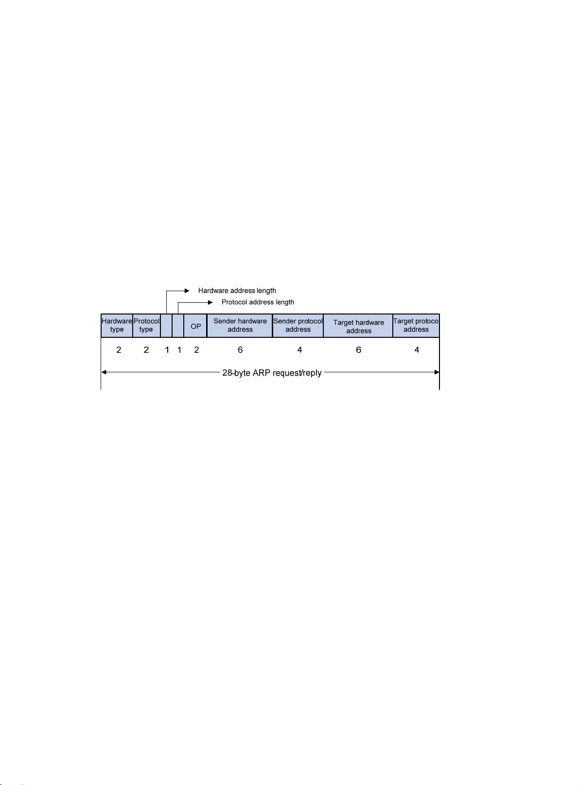
ARP messages include ARP requests and ARP replies. Figure 1 shows the format of the ARP
request/reply. Numbers in the figure refer to field lengths.
Figure 1 ARP message format
ARP message fields:
• Hardware type—The hardware address type. Value 1 represents Ethernet.
• Protocol type—The type of the protocol address to be mapped. The hexadecimal value
0x0800 represents IP.
• Hardware address length and protocol address length—Length, in bytes, of a hardware
address and a protocol address. For an Ethernet address, the value of the hardware address
length field is 6. For an IPv4 address, the value of the protocol address length field is 4.
• OP—Operation code, which describes type of the ARP message. Value 1 represents an ARP
request, and value 2 represents an ARP reply.
• Sender hardware address—Hardware address of the device sending the message.
• Sender protocol address—Protocol address of the device sendin g the message.
• Target hardware address—Hardware address of the device to which the message is being
sent.
• Target protocol address—Protocol address of the device to which the messag e is being sent.
ARP operation
If Host A and Host B are on the same subnet and Host A sends a packet to Host B, as shown
in Figure 2, the resolution process is:
1. Host A looks in its ARP table to see whether there is an ARP entry for Host B. If yes, Host A
uses the MAC address in the entry to encapsulate the IP packet into a data link layer frame and
sends the frame to Host B.
1
Page 12
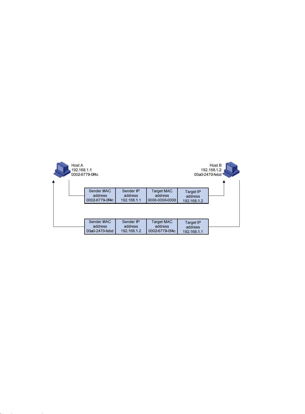
2. If Host A finds no entry for Host B, Host A buffers the packet and broadcasts an ARP request
using the following information:
{ Source IP address and source MAC address—Host A’s own IP address and the MAC
address
{ Target IP address—Host B’s IP address
{ Target MAC address—An all-zero MAC address
All hosts on this subnet can receive the broadcast request, but only the requested host (Host B)
processes the request.
3. Host B compares its own IP address with the target IP address in the ARP request. If they are
the same, Host B:
a. Adds the sender IP address and sender MAC address into its ARP table.
b. Encapsulates its MAC add ress into an ARP reply.
c. Unicasts the ARP reply to Host A.
4. After receiving the ARP reply, Host A:
a. Adds the MAC address of Host B to its ARP table.
b. Encapsulates the MAC add ress into the packet and sends it to Host B.
Figure 2 ARP address resolution process
If Host A and Host B are on different subnets, the resolution process is as follows:
1. Host A sends an ARP request to the gateway. The target IP address in the ARP request is the
IP address of the gateway.
2. After obtaining the MAC address of the gateway from an ARP reply, Host A sends the packet to
the gateway.
3. If the gateway maintains the ARP entry of Host B, it forwards the packet to Host B directly; if not,
it broadcasts an ARP request, in which the target IP address is the IP address of Host B.
4. After obtaining the MAC address of Host B, the gateway sends the packet to Host B.
ARP table
An ARP table stores dynamic and static ARP entries.
Dynamic ARP entry
ARP automatically creates and updates dynamic entries. A dynamic ARP entry is removed when its
aging timer expires or the output interface goes down, and it can be overwritten b y a static ARP entry .
Static ARP entry
A static ARP entry is manually configured and maintained. It does not age out, and cannot be
overwritten by a dynamic ARP entry.
2
Page 13

Static ARP entries protect communication between devices, because attack packets cannot modify
the IP-to-MAC mapping in a static ARP entry.
Static ARP entries can be classified into long, and short ARP entries.
• To configure a long static ARP entry, specify the IP address, MAC address, VLAN, and output
interface. A long static ARP entry is directly used for forwarding matching packets. To allow
communication with a host using a fixed IP-to-MAC mapping through a specific interface in a
specific VLAN, configure a long static ARP entry for it.
• To configure a short static ARP entry, you only need to specify the IP address and MAC
address.
If the output interface is a VLAN interface, the device first sends an ARP request whose target
IP address is the IP address of the short entry. If the sender IP and MAC addresses in the
received ARP reply match the IP and MAC addresses of the short static ARP entry, the device
adds the interface receiving the ARP reply to the short static ARP entry, and then uses the
resolved entry to forward the matching IP packets.
To communicate with a host by using a fixed IP-to-MAC mapping, configure a short static ARP
entry for it.
Configuring a static ARP entry
A static ARP entry is effective when the device it corresponds to works properly. However, when a
VLAN or VLAN interface is deleted, any static ARP entry corresponding to it will also be deleted (if it
is a long static ARP entry) or will become unresolved (if it is a short and resolved static ARP entry).
Follow these guidelines when you configure a long static ARP entry:
• The vlan-id argument must be the ID of an existing VLAN where the ARP entry resides. The
specified Ethernet interface must belong to that VLAN. The VLAN interface of the VLAN must
be created.
• The IP address of the VLAN interface of the VLAN specified by the vlan-id argument must
belong to the same subnet as the IP address specified by the ip-address argument.
To configure a static ARP entry:
Step Command Remarks
1. Enter system view.
2. Configure a static ARP
entry.
system-view
• Configure a long static ARP entry:
arp static ip-address mac-address vlan-id
interface-type interface-number
• Configure a short static ARP entry:
arp static ip-address mac-address
N/A
Use either command.
Configuring the maximum number of dynamic ARP entries for an interface
An interface can dynamically learn ARP entries. To prevent an interface from holding too many ARP
entries, you can set the maximum number of dynamic ARP entries that an interface can learn. When
the maximum number is reached, the interface stops learning ARP entries.
3
Page 14

A Layer 2 interface can learn an ARP entry only when both its maximum number and the VLAN
interface's maximum number are not reached.
To set the maximum number of dynamic ARP entries that an interface can learn:
Step Command Remarks
1. Enter system view.
2. Enter Ethernet interface view.
3. Set the maximum number of
dynamic ARP entries that the
interface can learn.
system-view
interface
interface-number
arp max-learning-num
number
interface-type
N/A
N/A
Optional.
By default, a Layer 2 interface does not
limit the number of dynamic ARP
entries. A Layer 3 interface on the HPE
3100 48 v2 Switch can learn up to 2048
dynamic ARP entries.
If the value of the number argument is
set to 0, the interface is disabled from
learning dynamic ARP entries.
Setting the aging timer for dynamic ARP entries
Each dynamic ARP entry in the ARP table has a limited lifetime, called aging timer. The aging timer
of a dynamic ARP entry is reset each tim e the dynamic ARP entry is updated. Dynamic ARP entries
that are not updated before their aging timers expire are deleted from the ARP table.
To set the age timer for dynamic ARP entries:
Step Command Remarks
1. Enter system view.
2. Set the age timer for dynamic
ARP entries.
system-view
arp timer aging
aging-time
Enabling dynamic ARP entry check
The dynamic ARP entry check function controls whether the device supports dynamic ARP entries
with multicast MAC addresses.
When dynamic ARP entry check is enabled, the dev ice cannot learn dynamic ARP entries containing
multicast MAC addresses.
When dynamic ARP entry check is disabled, the device can learn dynamic ARP entries containing
multicast MAC addresses.
To enable dynamic ARP entry check:
Step Command Remarks
1. Enter system view.
2. Enable dynamic ARP
entry check.
system-view
arp check enable
N/A
Optional.
Enabled by default.
N/A
Optional.
20 minutes by default.
4
Page 15
Configuring ARP quick update
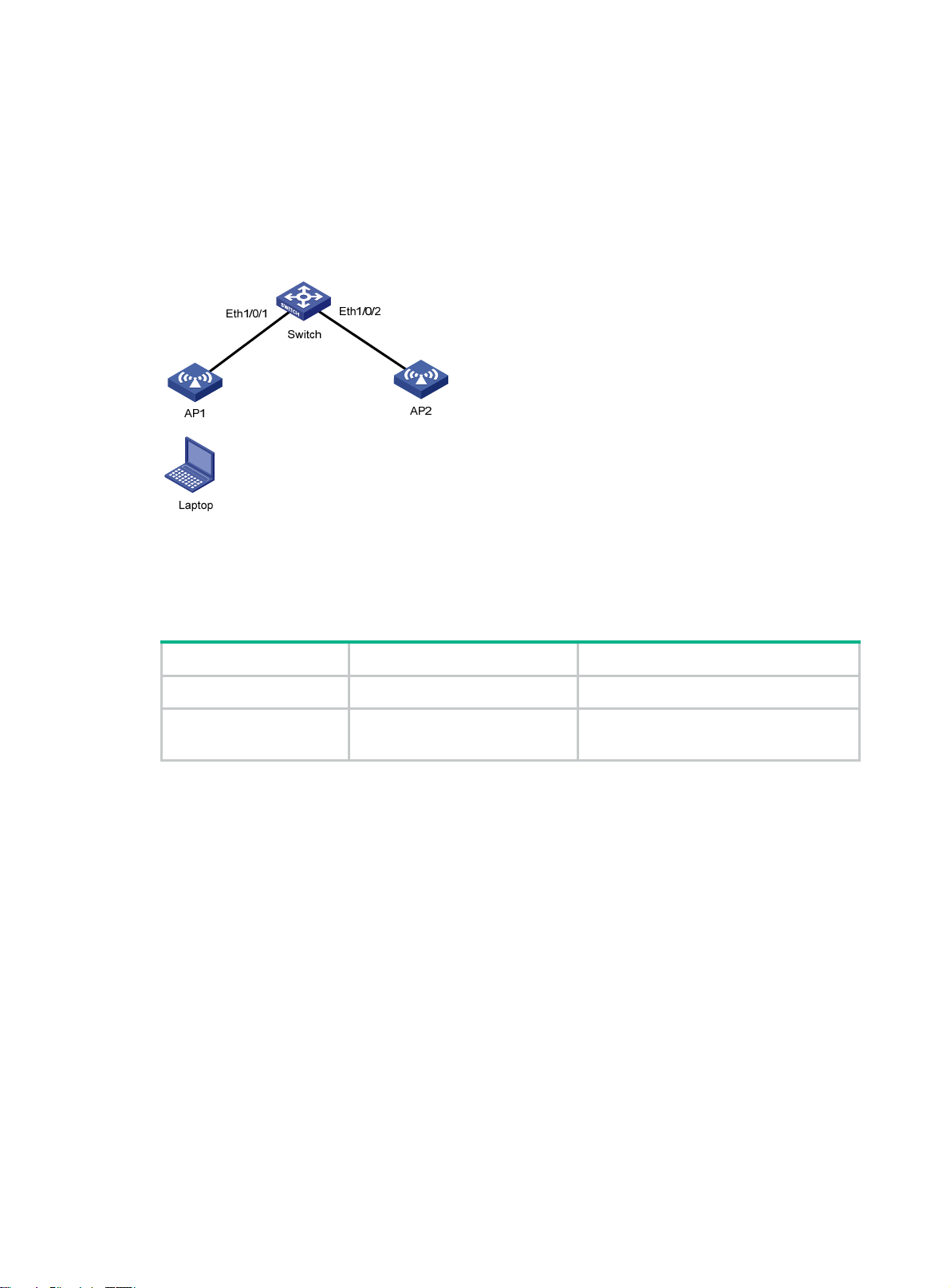
Hewlett Packard Enterprise recommends you enable ARP quick update in WLAN networks only.
As shown in Figure 3, the laptop frequently roams between AP 1 and AP 2. This af fects the mapping
between its MAC address and output interface on the switch. If the switch does not update its ARP
table immediately after the output interface changes, it might fail to communicate with the laptop.
Figure 3 ARP quick update application scenario
With ARP qui ck update en abled, the switch update s the corre sponding ARP entry immediately after
the change of the mapping between a MAC address and an output interface to en sure nonstop data
forwarding.
To enable ARP quick update:
Step Command Remarks
1. Enter system view.
2. Enable ARP quick
update.
system-view
mac-address station-move
quick-notify enable
Configuring multicast ARP
Microsoft Network Load Balancing (NLB) is a load balancing technology for server clustering
developed on Windows Server .
NLB supports load sharing and redundancy among servers within a cluster. To implement fast
failover, NLB require s that the switch forwards network traf fic to all servers or specified servers in the
cluster, and e ach server filters out unexpected traf fic. In a medium or small data center that uses the
Windows Server operating system, the proper cooperation of the switch and NLB is very important.
For more information about NLB, see the related documents of Windows Sever.
Microsoft NLB provides the following packet sending modes to make the switch forward network
traffic to all servers or specified servers:
• Unicast mode—NLB assigns each cluster member a common MAC address, which is the
cluster MAC address, and changes the source MAC address of each sent packet. Thus, the
switch cannot add the cluster MAC address to its MAC table. In addition, because the cluster
MAC address is unknown to the switch, packets destined to it are forwarded on all the ports of
the switch.
• Multicast mode—NLB uses a multicast MAC address that is a virtual MAC address for n etwork
communication, for example 0300-5e11-1111.
N/A
Optional.
Disabled by default.
5
Page 16

NOTE:
Multicast ARP is applicable to only multicast-mode NLB.
To configure multicast ARP:
Step Command Remarks
1. Disable the ARP entry
check function.
undo arp check enable
N/A
2. Configure a static ARP
entry.
3. Configure a static multicast
MAC address entry.
arp static
vlan-id interface-type
interface-number
mac-address multicast
mac-address
vlan
ip-address mac-address
vlan-id
interface
interface-list
Displaying and maintaining ARP
CAUTION:
Clearing ARP entries from the ARP table might cause communication failures.
Task Command Remarks
Display ARP entries in the ARP
table.
Display the ARP entry for a
specified IP address.
display arp
slot-number ] |
interface-type interface-number ] [
verbose
regular-expression ]
display arp
verbose
[
regular-expression ]
all
dynamic
[ [
|
vlan
vlan-id |
begin
] [ | {
ip-address [
| { begin | exclude | include
] [
exclude
|
static
|
interface
|
slot
slot-number ]
] [
count
include
Optional.
See IP Multicast Command
Reference.
slot
Available in any view
|
}
Available in any view
}
Display the age timer for dynamic
ARP entries.
Clear ARP entries from the ARP
table.
display arp timer aging
include
|
reset arp
slot-number |
interface-number }
} regular-expression ]
all
dynamic
{
|
interface
begin
[ | {
static
|
interface-type
ARP configuration examples
Static ARP entry configuration example
Network requirements
As shown in Figure 4, hosts are connected to the switch, which is connected to the router through
interface Ethernet 1/0/1 in VLAN 10. The IP and MAC addresses of the router are 192.168.1.1/24
and 00e0-fc01-0000 respectively.
To prevent malicious users from attacking the switch and enhance security for communications
between the router and switch, configure a static ARP entry for the router on the switch.
6
|
exclude
|
slot
Available in any view
Available in user view
Page 17
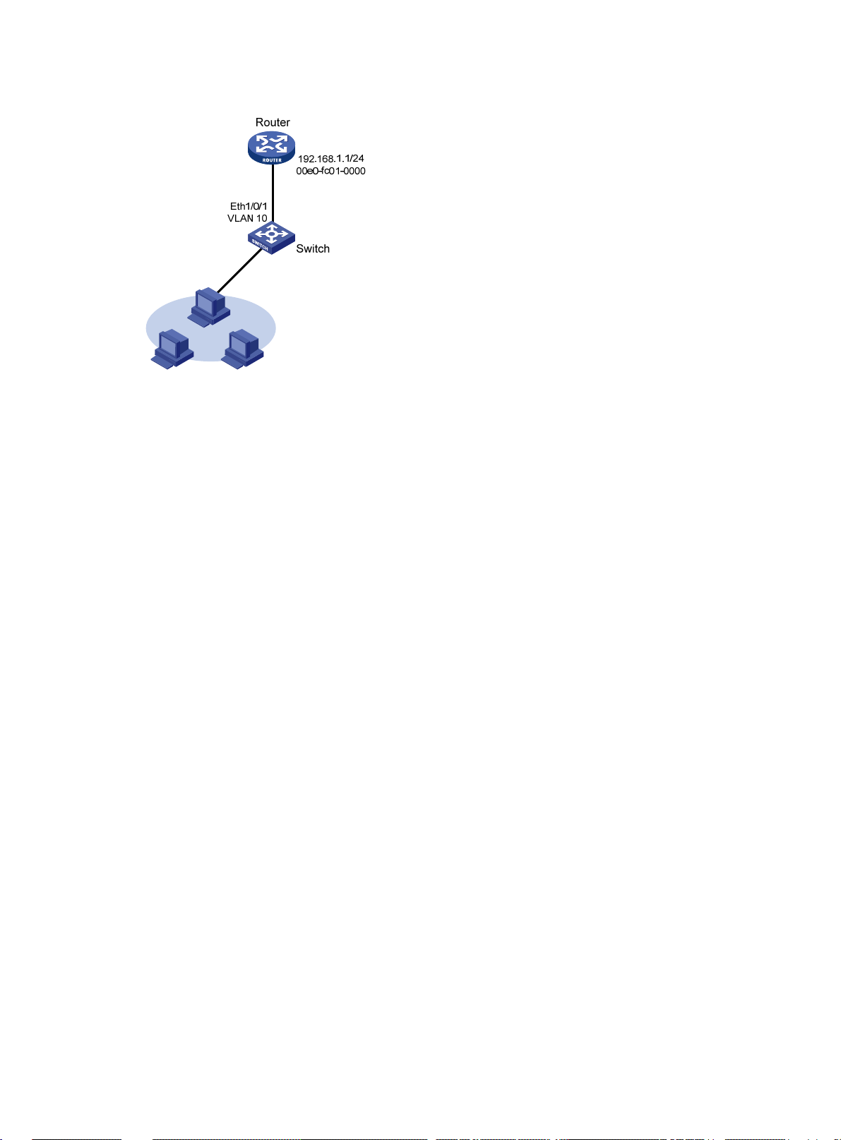
Figure 4 Network diagram
Configuration procedure
Configure the switch:
# Create VLAN 10.
<Switch> system-view
[Switch] vlan 10
[Switch-vlan10] quit
# Add interface Ethernet 1/0/1 to VLAN 10.
[Switch] interface Ethernet 1/0/1
[Switch-Ethernet1/0/1] port link-type trunk
[Switch-Ethernet1/0/1] port trunk permit vlan 10
[Switch-Ethernet1/0/1] quit
# Create interface VLAN-interface 10 and configure its IP address.
[Switch] interface vlan-interface 10
[Switch-vlan-interface10] ip address 192.168.1.2 24
[Switch-vlan-interface10] quit
# Configure a static ARP entry that has IP address 192.168.1.1, MAC addres s 00e0-f c01-0 000, and
output interface Ethernet 1/0/1 in VLAN 10.
[Switch] arp static 192.168.1.1 00e0-fc01-0000 10 Ethernet 1/0/1
# Display information about static ARP entries.
[Switch] display arp static
Type: S-Static D-Dynamic A-Authorized
IP Address MAC Address VLAN ID Interface Aging Type
192.168.1.1 00e0-fc01-0000 10 Eth1/0/1 N/A S
Multicast ARP configuration example
Network requirements
As shown in Figure 5, a small data center uses Microsoft multicast-mode NLB. To enable the
switches to cooperate with NLB, configure the following:
• Add Ethernet 1/0/2 and Ethernet 1/0/3 into VLAN 1, and specify IP address 16.1.1.30/24 for
VLAN-interface 1.
7
Page 18
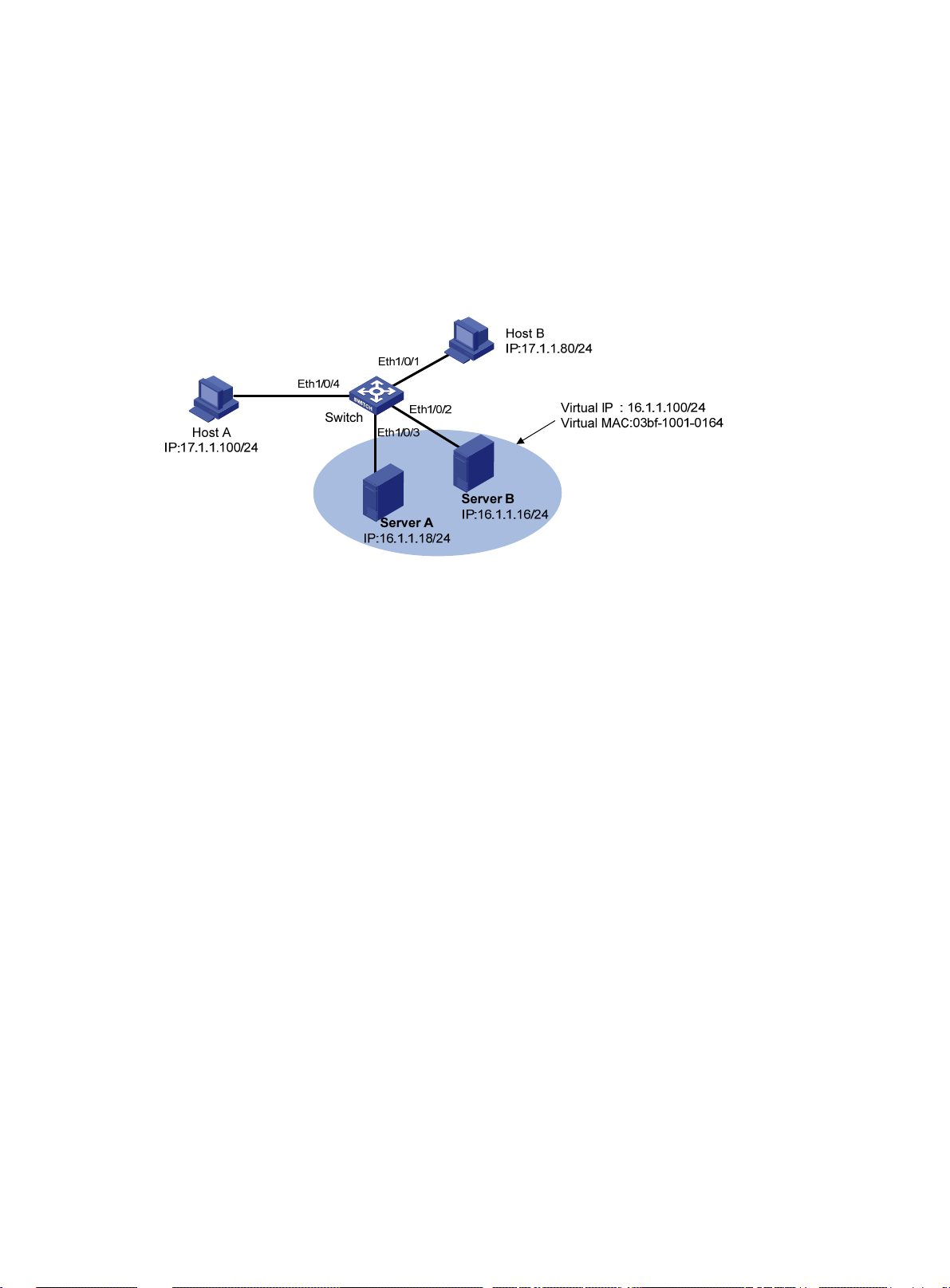
• Add Ethernet 1/0/1 and Ethernet 1/0/4 into VLAN 2, and specify IP address 17.1.1.1/24 for
VLAN-interface 2.
• Specify 17.1.1.1/24 as the default gateway of Host A and Host B.
• Specify 16.1.1.30/24 as the default gateway of Server A and Server B.
• Disable the ARP entry check function so that the switch can learn dynamic ARP entries
containing multicast MAC addresses.
• Configure a static multicast MAC address entry so that only interfaces Ethernet 1/0/2 and
Ethernet 1/0/3 can receive multicast information.
Figure 5 Network diagram
Configuration procedure
This example only describes multicast ARP configuration on the switch, and is only applicable to
multicast NLB. For NLB configuration on the servers, see the related documents of the Windows
Server.
# Specify an IP address for VLAN-interface 2.
<Switch> system-view
[Switch] vlan 2
[Switch-vlan2] port Ethernet 1/0/4
[Switch-vlan2] port Ethernet 1/0/1
[Switch-vlan2] quit
[Switch] interface vlan-interface 2
[Switch-Vlan-interface2] ip address 17.1.1.1 255.255.255.0
[Switch-Vlan-interface2] quit
# Specify an IP address for VLAN-interface 1.
[Switch] interface vlan-interface 1
[Switch-Vlan-interface1] ip address 16.1.1.30 255.255.255.0
[Switch-Vlan-interface1] quit
# Disable the ARP entry check function.
[Switch] undo arp check enable
# Configure a static multicast MAC address entry.
[Switch] mac-address multicast 03bf-1001-0164 interface Ethernet 1/0/2 Ethernet 1/0/3 vlan
1
Verifying the configuration
• NLB load sharing—Enables the FTP server function of Server A and Server B. Host A and
Host B send requests to the virtual IP address and each of them logs in to a dif f erent server.
8
Page 19

• NLB redundancy—Disables the network interface card of Server A. Host A and Host B send
requests to the virtual IP address and both log in to the FTP server on Server B.
9
Page 20

Configuring gratuitous ARP
Overview
In a gratuitous ARP packet, the sender IP address and the target IP address are the IP address of
the sending device.
A device sends a gratuitous ARP packet for either of the following purposes:
• Determine whether its IP address is already used by another device. If the IP address is already
used, the device is informed of the conflict by an ARP reply.
• Inform other devices of a change of its MAC address.
Gratuitous ARP packet learning
This feature enables a device to create or update ARP entries by using the sender IP and MAC
addresses in received gratuitous ARP packets.
With this feature disabled, the device uses received gratuitous ARP packets to update existing ARP
entries only.
Periodic sending of gratuitous ARP packets
Enabling a device to periodically send gratuitous ARP packets helps downstream devices update
their corresponding ARP entries or MAC entries in time. This feature can be used to:
• Prevent gateway spoofing.
When an attacker sends forged gratuitous ARP packets to the hosts on a network, the traffic
destined for the gateway from the hosts is sent to the attacker instead. As a result, the hosts
cannot access the external network.
To prevent gateway spoofing attacks, enable the gateway to send gratuitous ARP packets
containing its primary IP address and manually configured secondary IP addresses at a specific
interval, so hosts can learn correct gateway address information.
• Prevent ARP entries from aging out.
If network traffic is heavy or if a host’s CPU usage is high on a host, received ARP packets
might be discarded or not be processed in time. Eventually, the dynamic ARP entries on the
receiving host age out, and the traffic between the host and the corresponding devices is
interrupted until the host re-creates the ARP entries.
To prevent this problem, enable the gateway to send gratuitous ARP packets periodically. The
gratuitous ARP packets contain the gateway's primary IP address or one of its manually
configured secondary IP addresses, so the receiving host can update ARP entries in time,
ensuring traffic continuity.
Configuration guidelines
Follow these guidelines when you configure gratuitous ARP:
• You can enable periodic sending of gratuitous ARP packets in VLAN interface view.
• You can enable periodic sending of gratuitous ARP pa ckets on a maximum of 1024 interfaces.
• Periodic sending of gratuitous ARP packets takes effect only when the link of the enabled
interface goes up and an IP address has been assigned to the interface.
10
Page 21

• If you change the interval for sending gratuitous ARP packets, the configuration is effective at
the next sending interval.
• The frequency of sending gratuitous ARP packets might be much lower than is expected if this
function is enabled on multiple interfaces, if each interface is configu red with multiple secondary
IP addresses, or if a small sending interval is configured in such cases.
Configuration procedure
To configure gratuitous ARP:
Step Command Remarks
1. Enter system view.
2. Enable learning of gratuitous
ARP packets.
3. Enable the device to send
gratuitous ARP packets upon
receiving ARP requests from
another subnet.
4. Enter interface view.
5. Enable periodic sending of
gratuitous ARP packets and
set the sending interval.
system-view
gratuitous-arp-learning
enable
gratuitous-arp-sending
enable
interface
interface-number
arp send-gratuitous-arp
interval
[
interface-type
milliseconds ]
Enabling IP conflict notification
If the sender IP address of a received gratuitous ARP packet is being used by the receiving device,
by default, the receiving device sends a gratuitous ARP request, and it displays an error message
after it receives an ARP reply. The receiving device repeats the default processing 5 seconds after
displaying the error message, and it stops the processing when the conflict is resolved.
You can use this command to enable the device to display error message without sending any
gratuitous ARP request for conflict confirmation. The receiving device displays the message every
30 seconds until the conflict is resolved.
N/A
Optional.
Enabled by default.
By default, a device does not send
gratuitous ARP packets upon
receiving ARP requests from
another subnet.
N/A
Disabled by default.
To enable IP conflict notification:
Step Command Remarks
1. Enter system view.
2. Enable IP conflict notification.
system-view
arp ip-conflict prompt
N/A
Optional.
Disabled by default.
11
Page 22
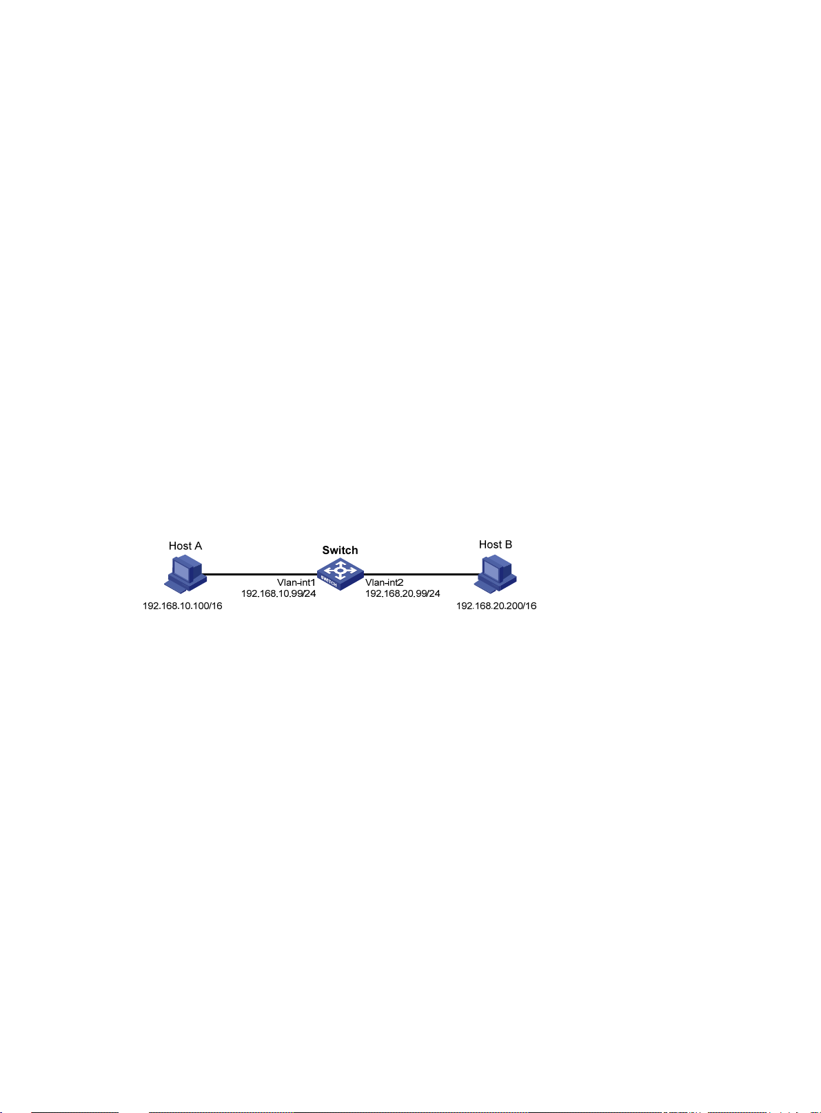
Configuring proxy ARP
Overview
Proxy ARP enables a device on a network to answer ARP requests for an IP address not on that
network. With proxy ARP, hosts on different broadcast domains can communicate with each other as
they do on the same network.
Proxy ARP includes common proxy ARP and local proxy ARP.
• Common proxy ARP—Allows communication between hosts that con nect to dif ferent Layer-3
interfaces and reside in different broadcast domains.
• Local proxy ARP—Allows communication between hosts that connect to the same Layer-3
interface and reside in different broadcast domains.
Common proxy ARP
A common proxy ARP enabled device allows host s that reside on dif ferent subnets to communicate.
As shown in Figure 6, Switch connects to two subnets through VLAN-interface 1 and VLAN-interface
2. The IP addresses of the two interfaces are 192.168.10.99/24 and 192.168.20.99/24. Host A and
Host B are assigned the same prefix 192.168.0.0. Host A connects to VLAN-interface 1 and Host B
connects to VLAN-interface 2.
Figure 6 Application environment of common proxy ARP
Because Host A and Host B have the same prefix 192.168.0.0, Host A considers that Host B is on the
same network, and it broadcasts an ARP request for the MAC address of Host B. However, Host B
cannot receive this request because it is in a different broadcast domain.
Y ou can common en able proxy ARP on VLAN-interface 1 of the switch so that the switch can reply to
the ARP request from Host A with the MAC address of VLAN-interface 1, and forward packets sent
from Host A to Host B. In this case, the switch acts as a proxy of Host B.
A main advantage of common proxy ARP is that you can enable it on a single switch without
disturbing routing tables of other routers in the network. Proxy ARP acts as the gateway for hosts
that are not configured with a default gateway or do not have routing capability.
Local proxy ARP
As shown in Figure 7, Host A and Host B belong to VLAN 2, but are isolated at Layer 2. Host A
connects to Ethernet 1/0/3 while Host B connects to Ethernet 1/0/1. Enable local proxy ARP on
Switch A to allow Layer 3 communication between the two hosts.
12
Page 23
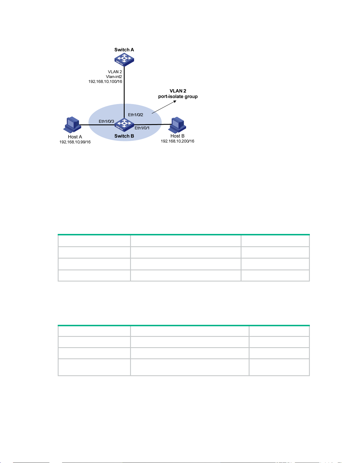
Figure 7 Application environment of local proxy ARP
Enable local proxy ARP in one of the following cases:
• Hosts connecting to different isolated La yer 2 port s in the sa me VLAN need to communicate at
Layer 3.
• If an isolate-user-VLAN is configured, hosts in different secondary VLANs of the
isolate-user-VLAN need to communicate at Layer 3.
Enabling common proxy ARP
To enable common proxy ARP in VLAN interface view
Step Command Remarks
1. Enter system view.
2. Enter interface view.
3. Enable proxy ARP.
system-view
interface
proxy-arp enable
interface-type interface-number
Enabling local proxy ARP
To enable local proxy ARP in VLAN interface view:
Step Command Remarks
1. Enter system view.
2. Enter interface view.
3. Enable local proxy ARP.
system-view
interface
local-proxy-arp enable
endIP ]
interface-type interface-number
ip-range
[
startIP to
N/A
N/A
Disabled by default
N/A
N/A
Disabled by default
Displaying and maintaining proxy ARP
13
Page 24
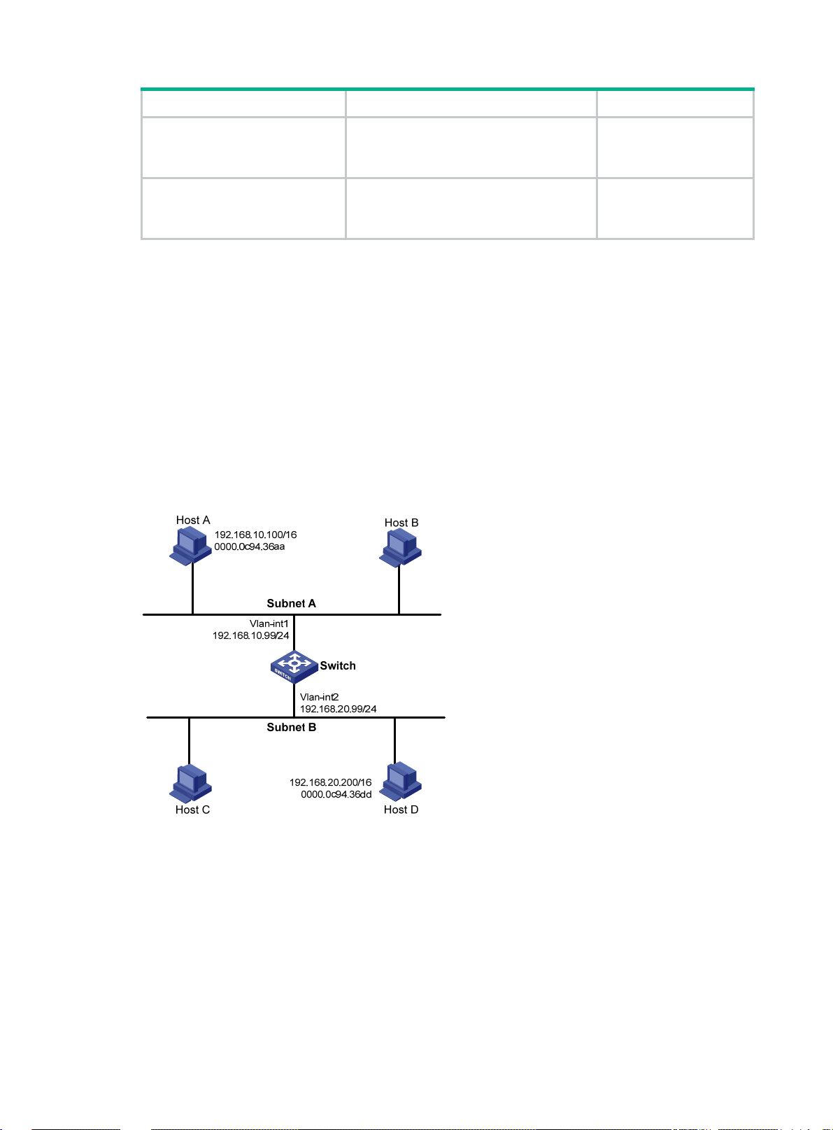
Task Command Remarks
Display whether common proxy
ARP is enabled.
Display whether local proxy ARP
is enabled.
display proxy-arp [ interface
interface-type interface-number ] [ | {
exclude
|
display local-proxy-arp [ interface
interface-type interface-number ] [ | {
exclude
|
include
|
include
|
} regular-expression ]
} regular-expression ]
begin
begin
Proxy ARP configuration examples
Common proxy ARP configuration example
Network requirements
As shown in Figure 8, Host A and Host D have the same IP prefix and mask (IP addre sses of Host A
and Host D are 192.168.10.100/16 and 192.168.20.200/16 respectively), but they are located on
different subnets separated by the switch (Host A belongs to VLAN 1 while Host D belongs to VLAN
2). As a result , Host D cannot receive or respond to any ARP request from Host A.
You must configure proxy ARP on the switch to enable communication between the two hosts.
Figure 8 Network diagram
Available in any view
Available in any view
Configuration procedure
# Create VLAN 2.
<Switch> system-view
[Switch] vlan 2
[Switch-vlan2] quit
# Specify the IP address of interface VLAN-interface 1.
[Switch] interface vlan-interface 1
[Switch-Vlan-interface1] ip address 192.168.10.99 255.255.255.0
# Enable proxy ARP on interface VLAN-interface 1.
14
Page 25
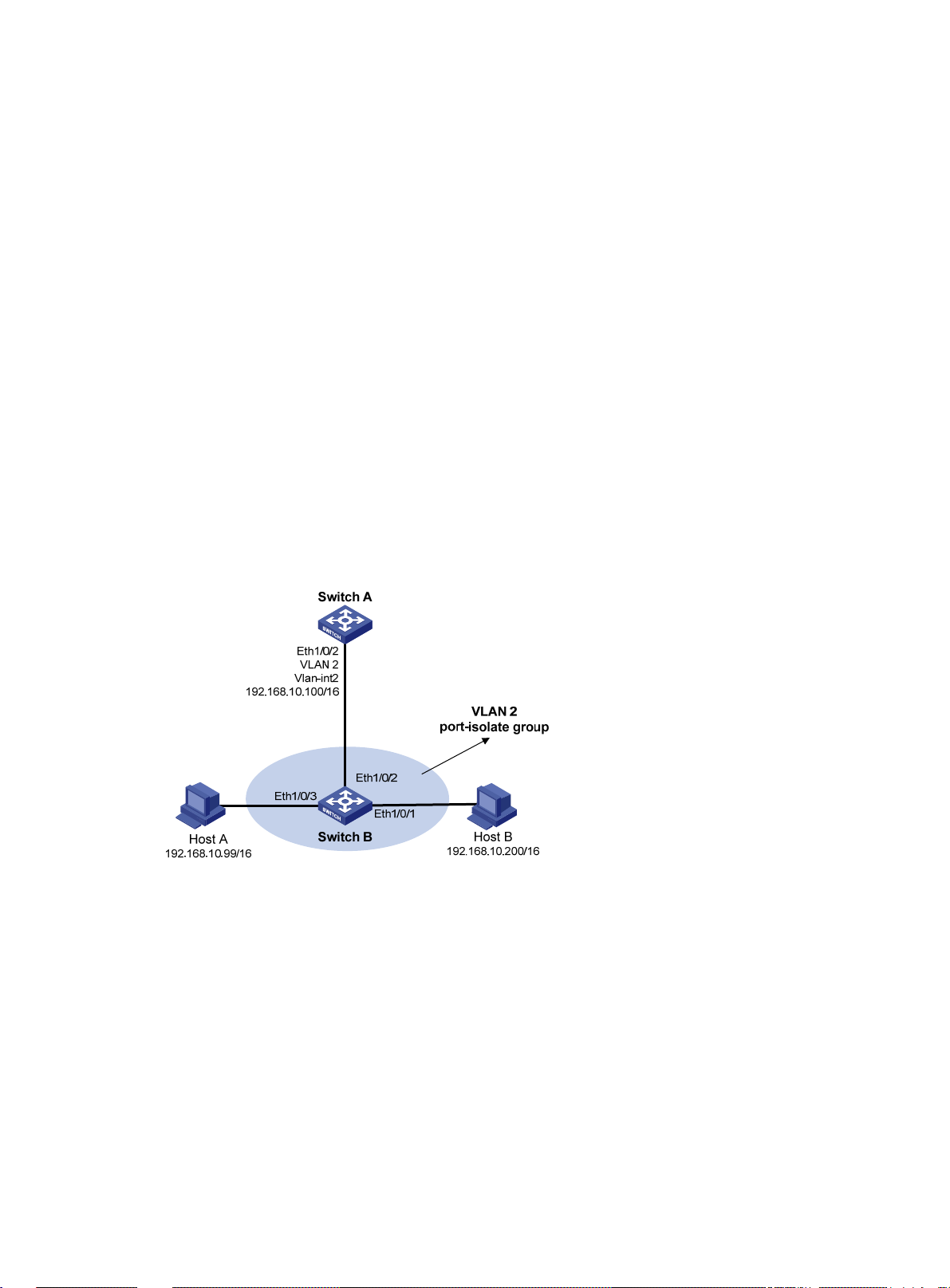
[Switch-Vlan-interface1] proxy-arp enable
[Switch-Vlan-interface1] quit
# Specify the IP address of interface VLAN-interface 2.
[Switch] interface vlan-interface 2
[Switch-Vlan-interface2] ip address 192.168.20.99 255.255.255.0
# Enable proxy ARP on interface VLAN-interface 2.
[Switch-Vlan-interface2] proxy-arp enable
After completing preceding configurations, use the ping command to verify the connectivity between
Host A and Host D.
Local proxy ARP configuration example in case of port isolation
Network requirements
As shown in Figure 9, Host A and Host B belong to the same VLAN, and connect to Switch B via
Ethernet 1/0/3 and Ethernet 1/0/1 respectively. Switch B connects to Switch A via Ethernet 1/0/2.
Configure port isolation on Ethernet 1/0/3 and Ethernet 1/0/1 of Switch B to isolate Host A from Host
B at Layer 2. Enable local proxy ARP on Switch A to allow communication between Host A and Host
B at Layer 3.
Figure 9 Network diagram
Configuration procedure
1. Configure Switch B:
# Add Ethernet 1/0/3, Ethernet 1/0/1 and Ethernet 1/0/2 to VLAN 2. Configure port isolation on
Host A and Host B.
<SwitchB> system-view
[SwitchB] vlan 2
[SwitchB-vlan2] port Ethernet 1/0/3
[SwitchB-vlan2] port Ethernet 1/0/1
[SwitchB-vlan2] port Ethernet 1/0/2
[SwitchB-vlan2] quit
[SwitchB] interface Ethernet 1/0/3
[SwitchB-Ethernet1/0/3] port-isolate enable
[SwitchB-Ethernet1/0/3] quit
15
Page 26
[SwitchB] interface Ethernet 1/0/1
[SwitchB-Ethernet1/0/1] port-isolate enable
[SwitchB-Ethernet1/0/1] quit
2. Configure Switch A:
# Create VLAN 2, and add Ethernet 1/0/2 to VLAN 2.
<SwitchA> system-view
[SwitchA] vlan 2
[SwitchA-vlan2] port Ethernet 1/0/2
[SwitchA-vlan2] quit
[SwitchA] interface vlan-interface 2
[SwitchA-Vlan-interface2] ip address 192.168.10.100 255.255.0.0
From Host A, ping Host B. The ping operation is unsuccessful because they are isolated at
Layer 2.
# Configure local proxy ARP to allow communication between Host A and Host B at Layer 3.
[SwitchA-Vlan-interface2] local-proxy-arp enable
From Host A, ping Host B. The ping operation is successful after the configuration.
Local proxy ARP configuration example in isolate-user-VLAN
Network requirements
As shown in Figure 10, Switch B is attached to Switch A. VLAN 5 on Switch B is an
isolate-user-VLAN, which includes uplink port Ethernet 1/0/2 and two secondary VLANs, VLAN 2
and VLAN 3. Ethernet 1/0/3 belongs to VLAN 2, and Ethernet 1/0/1 belongs to VLAN 3.
Host A belong s to VLAN 2 and connects to Ethernet 1/0/3 of Switch B. Host B belongs to VLAN 3 and
connects to Ethernet 1/0/1 of Switch B.
As Host A and Host B belong to different secondary VLANs, they are isolated at Layer 2. Configure
local proxy ARP on Switch A to implement Layer 3 communication between Host A and Host B.
Figure 10 Network diagram
192.168.10.100/16
Host A
192.168.10.99/16
Eth1/0/2
VLAN 5
Vlan-int5
Eth1/0/3
VLAN 2
Switch A
Eth1/0/2
VLAN 5
Switch B
Eth1/0/1
VLAN 3
Isolate-user-vlan 5
Secondary VLAN 2 and 3
Host B
192.168.10.200/16
Configuration procedure
1. Configure Switch B:
# Create VLAN 2, VLAN 3, and VLAN 5 on Switch B. Add Ethernet 1/0/3 to VLAN 2, Ethernet
1/0/1 to VLAN 3, and Ethernet 1/0/2 to VLAN 5. Configure VLAN 5 as the isolate-user-VLAN,
16
Page 27

and VLAN 2 and VLAN 3 as secondary VLANs. Configure the mappings between
isolate-user-VLAN and the secondary VLANs.
<SwitchB> system-view
[SwitchB] vlan 2
[SwitchB-vlan2] port Ethernet 1/0/3
[SwitchB-vlan2] quit
[SwitchB] vlan 3
[SwitchB-vlan3] port Ethernet 1/0/1
[SwitchB-vlan3] quit
[SwitchB] vlan 5
[SwitchB-vlan5] port Ethernet 1/0/2
[SwitchB-vlan5] isolate-user-vlan enable
[SwitchB-vlan5] quit
[SwitchB] interface Ethernet 1/0/2
[SwitchB-Ethernet1/0/2] port isolate-user-vlan 5 promiscuous
[SwitchB-Ethernet1/0/2] quit
[SwitchB] interface Ethernet 1/0/1
[SwitchB-Ethernet1/0/1] port isolate-user-vlan host
[SwitchB-Ethernet1/0/1] quit
[SwitchB] interface Ethernet 1/0/3
[SwitchB-Ethernet1/0/3] port isolate-user-vlan host
[SwitchB-Ethernet1/0/3] quit
[SwitchB] isolate-user-vlan 5 secondary 2 3
2. Configure Switch A:
# Create VLAN 5 and add Ethernet 1/0/2 to it.
<SwitchA> system-view
[SwitchA] vlan 5
[SwitchA-vlan5] port Ethernet 1/0/2
[SwitchA-vlan5] quit
[SwitchA] interface vlan-interface 5
[SwitchA-Vlan-interface5] ip address 192.168.10.100 255.255.0.0
From Host A, ping Host B. The ping operation is unsuccessful because they are isolated at
Layer 2.
# Configure local proxy ARP to implement Layer 3 communication between Host A and Host B.
[SwitchA-Vlan-interface5] local-proxy-arp enable
From Host A, ping Host B. The ping operation is successful after the configuration.
17
Page 28

Configuring ARP snooping
Overview
The ARP snooping feature is used in Layer 2 switching networks. It creates ARP snooping entries
using ARP packets, and the entries can be used by manual-mode MFF to answer ARP reque sts from
a gateway. For more information about MFF, see Security Configuration Guide.
If ARP snooping is enabled on a VLAN of a device, ARP packets received by the interfaces of the
VLAN are redirected to the CPU. The CPU uses ARP packets to create ARP snooping entries
comprising source IP and MAC addresses, VLAN and receiving port information.
The aging time and valid period of an ARP snooping entry are 25 minutes and 15 minutes,
respectively. If an ARP snooping entry is not updated within 15 minutes, it becomes invalid and
cannot be used. After that, if an ARP packet whose source IP and MAC addresses correspond with
the entry is received, the entry becomes valid, and its age timer restarts. If the age timer of an ARP
entry expires, the entry is removed.
If the ARP snooping device receives an ARP packet that has the same sender IP address as but a
different sender MAC address from a vali d ARP snooping entry , it considers that an attack occurs. An
ARP snooping entry conflict occurs in this case. As a result, the ARP snooping entry becomes invalid
and is removed after 25 minutes.
Configuration procedure
To enable ARP snooping fo r a VLAN:
Step Command Remarks
1. Enter system view.
2. Enter VLAN view.
3. Enable ARP snooping.
system-view
vlan
vlan-id
arp-snooping enable
N/A
N/A
Disabled by default
Displaying and maintaining ARP snooping
Task Command Remarks
Display ARP snooping entries.
Remove ARP snooping entries.
display arp-snooping [ ip
vlan
vlan-id ] [ | {
include
} regular-expression ]
reset arp-snooping [ ip
vlan-id ]
begin
ip-address |
exclude
|
ip-address |
|
vlan
Available in any view
Available in user view
18
Page 29
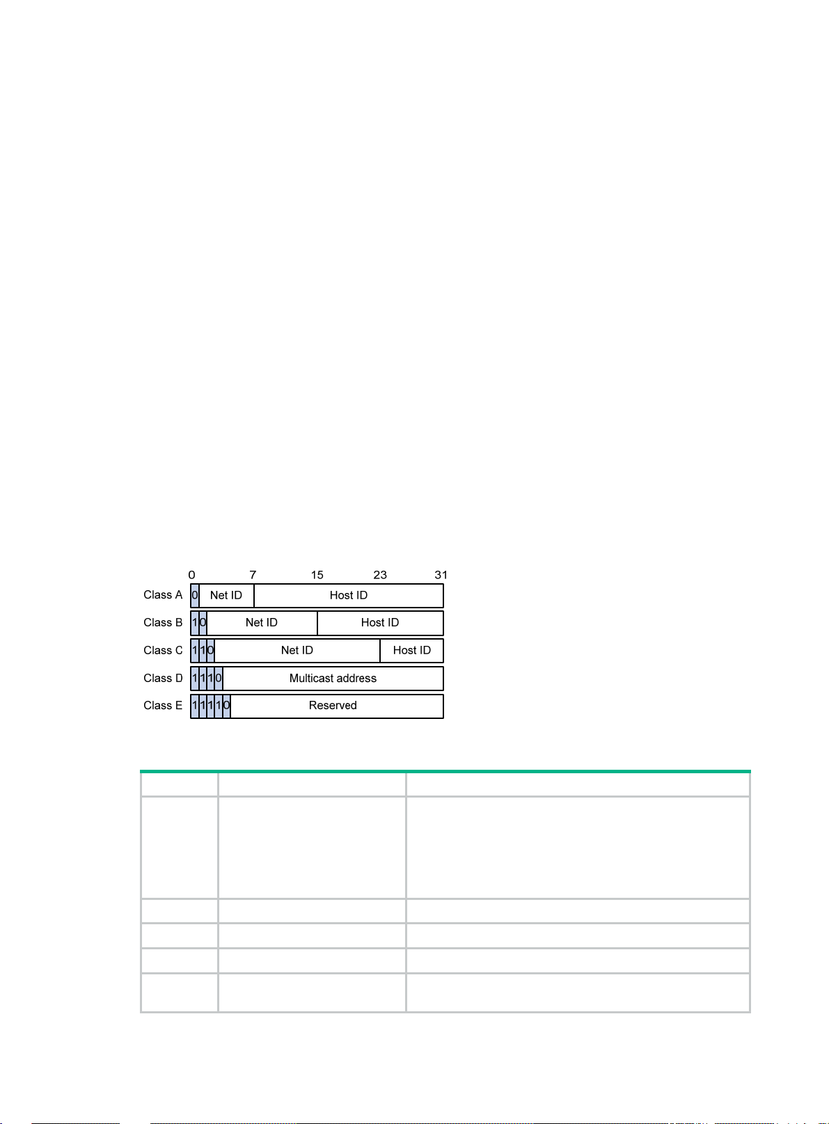
Configuring IP addressing
This chapter describes IP addressing basic and manual IP address assignment for interfaces.
Dynamic IP address assignment (BOOTP and DHCP) are beyond the scope of this chapter.
The term "interface" in this chapter collectively refers to VLAN interfaces.
Overview
This section describes the IP addressing basics.
IP addressing uses a 32-bit address to identify each host on a network. To make addresses easier to
read, they are written in dotted decimal notation, each address being four octets in length. For
example, address 00001010000000010000000100000001 in binary is written as 10.1.1.1.
IP address classes
Each IP address breaks down into two parts:
• Net ID—Identifies a network. The first several bits of a net ID, known as the class field or class
bits, identify the class of the IP address.
• Host ID—Identifies a host on a network.
IP addresses are divided into five classes, shown in Figure 11. The shaded areas represent the
address class. The first three classes are widely used.
Figure 11 IP address classes
Table 1 IP address classes and ranges
Class Address range Remarks
The IP address 0.0.0.0 is used by a host at startup for
temporary communication. This address is never a valid
A 0.0.0.0 to 127.255.255.255
B 128.0.0.0 to 191.255.255.255 N/A
destination address.
Addresses starting with 127 are reserved for loopback test.
Packets destined to these addresses are processed locally
as input packets rather than sent to the link.
C 192.0.0.0 to 223.255.255.255 N/A
D 224.0.0.0 to 239.255.255.255 Multicast addresses.
E 240.0.0.0 to 255.255.255.255
Reserved for future use except for the broadcast address
255.255.255.255.
19
Page 30

Special IP addresses
The following IP addresses are for special use and cannot be used as ho st IP addresses.
• IP address with an all-zero net ID—Identifies a host on the local network. For example, IP
address 0.0.0.16 indicates the host with a host ID of 16 on the local network.
• IP address with an all-zero host ID—Identifies a network.
• IP address with an all-one host ID—Identifies a directed broadcast address. For example, a
packet with the destination address of 192.168.1.255 will be broadcast to all the hosts on the
network 192.168.1.0.
Subnetting and masking
Subnetting divides a network down into smaller networks called subnets by using some bits of the
host ID to create a subnet ID.
Masking identifies the boundary between the host ID and the combination of net ID and subnet ID.
(When subnetting is not adopted, a mask identifies the boundary between the net ID and the host
ID.)
Each subnet mask is made up of 32 bits that correspond to the bits in an IP address. In a subnet
mask, consecutive ones represent the net ID and subnet ID, and consecutive zeros represent the
host ID.
Before being subnetted, Class A, B, and C networks use the following default masks (also called
natural masks): 255.0.0.0, 255.255.0.0, and 255.255.255.0 respectively.
Figure 12 shows how a Class B network is subnetted.
Figure 12 Subnetting a Class B network
Subnetting increases the number of addresses that cannot be assigned to hosts. After being
subnetted, a network can accommodate fewer hosts.
For example, a Class B network without subnetting can accommodate 1022 more hosts than the
same network subnetted into 512 subnets.
16
• Without subnetting—65,534 hosts (2
address, which has an all-one host ID, and the netwo rk address, which has an all-zero host I D.)
• With subnetting—Using the first 9 bits of the host-id for subnetting provides 512 (2
However, only 7 bits remain available for the host ID. This allows 126 (2
subnet, a total of 64,512 hosts (512 × 126).
– 2). (The two deducted addresses are the broadcast
9
7
– 2) hosts in each
) subnets.
Assigning an IP address to an interface
You can assign an interface one primary address and multiple secondary addresses.
Generally, you only need to assign the primary address to an interface. In some cases, you need to
assign secondary IP addresses to the interface. For example, if the interface connects to two
subnets, to enable the device to communicate with all hosts on the LAN, you need to assign a
primary IP address and a secondary IP address to the interface.
20
Page 31

Configuration guidelines
Follow these guidelines when you assign an IP address to an interface:
• Each interface has only one primary IP address. A newly configured primary IP address
overwrites the previous one.
• You cannot assign secondary IP addresses to an interface that obtains an IP address through
BOOTP or DHCP.
• The primary and secondary IP addresses you assign to the interface can be located on the
same network segment, but different interfaces on your device must re side on different network
segments.
• Y ou can manually assign an IP address to an interface, or configure the interface to obtain a n IP
address through BOOTP or DHCP. If you change the way an interface obtains an IP address,
the new IP address overwrites the previous one.
• The switch supports a 31-bit subnet mask (the mask 255.255.255.254) for saving IP addresses
in the point-to-point communication.
Configuration procedure
To assign an IP address to an interface:
Step Command Remarks
1. Enter system view.
2. Enter interface view.
3. Assign an IP address to
the interface.
system-view
interface
interface-number
ip address
{ mask-length | mask } [
Configuration example
Network requirements
As shown in Figure 13, a port in VLAN 1 on a switch is connected to a LAN co mprising two segments:
172.16.1.0/24 and 172.16.2.0/24.
T o enable the hosts on the two subnets to communicat e with the external network through the switch,
and to enable the hosts on the two subnets to communicate with each other:
• Assign a primary IP address and a secondary IP address to VLAN-interface 1 on the switch.
• Set the primary IP address of VLAN-interface 1 as the gateway address of the hosts o n subnet
172.16.1.0/24, and the secondary IP address of VLAN-interface 1 as the gateway address of
the hosts on subnet 172.16.2.0/24.
interface-type
ip-address
sub
N/A
N/A
By default, no IP address is assigned to
]
any interface.
21
Page 32

Figure 13 Network diagram
172.16.1.0/24
Configuration procedure
# Assign a pri m ary IP address and a secondary IP address to VLAN-interface 1.
<Switch> system-view
[Switch] interface vlan-interface 1
[Switch-Vlan-interface1] ip address 172.16.1.1 255.255.255.0
[Switch-Vlan-interface1] ip address 172.16.2.1 255.255.255.0 sub
172.16.1.2/24
172.16.2.0/24
Host B
172.16.2.2/24
Switch
Vlan-int1
172.16.1.1/24
172.16.2.1/24 sub
Host A
# Set the gateway address to 172.16.1.1 on the hosts attached to subnet 172.16.1.0/24, and to
172.16.2.1 on the hosts attached to subnet 172.16.2.0/24.
# From the switch, ping a host on subnet 172.16.1.0/24 to verify the connectivity.
<Switch> ping 172.16.1.2
PING 172.16.1.2: 56 data bytes, press CTRL_C to break
Reply from 172.16.1.2: bytes=56 Sequence=1 ttl=255 time=25 ms
Reply from 172.16.1.2: bytes=56 Sequence=2 ttl=255 time=27 ms
Reply from 172.16.1.2: bytes=56 Sequence=3 ttl=255 time=26 ms
Reply from 172.16.1.2: bytes=56 Sequence=4 ttl=255 time=26 ms
Reply from 172.16.1.2: bytes=56 Sequence=5 ttl=255 time=26 ms
--- 172.16.1.2 ping statistics ---
5 packet(s) transmitted
5 packet(s) received
0.00% packet loss
round-trip min/avg/max = 25/26/27 ms
The output shows that the switch can communicate with the hosts on subnet 172.16.1.0/24.
# From the switch, ping a host on subnet 172.16.2.0/24 to verify the connectivity.
<Switch> ping 172.16.2.2
PING 172.16.2.2: 56 data bytes, press CTRL_C to break
Reply from 172.16.2.2: bytes=56 Sequence=1 ttl=255 time=25 ms
Reply from 172.16.2.2: bytes=56 Sequence=2 ttl=255 time=26 ms
Reply from 172.16.2.2: bytes=56 Sequence=3 ttl=255 time=26 ms
Reply from 172.16.2.2: bytes=56 Sequence=4 ttl=255 time=26 ms
22
Page 33

Reply from 172.16.2.2: bytes=56 Sequence=5 ttl=255 time=26 ms
--- 172.16.2.2 ping statistics ---
5 packet(s) transmitted
5 packet(s) received
0.00% packet loss
round-trip min/avg/max = 25/25/26 ms
The output shows that the switch can communicate with the hosts on subnet 172.16.2.0/24.
# From a host on subnet 172.16.2.0/24, ping a host on subnet 172.16.1.0/24 to verify the connectivity .
Host B can be successfully pinged from Host A.
Configuring IP unnumbered
Overview
Logically, to enable IP on an interface, you must assign this interface a unique IP address. Yet, you
can borrow an IP address already configured on one of other interface s on your device instead. This
is called "IP unnumbered" and the interface borrowing the IP address is called "IP unnumbered
interface".
You can use IP unnumbered to save IP addresses either when available IP addresses are
inadequate or when an interface is brought up only for occasional use.
Configuration guidelines
Follow these guidelines when you configure IP unnum bered on an interface:
• An interface cannot borrow an IP address from an unnumbered interface.
• Multiple interfaces can use the same unnumbered IP address.
• If an interface has multiple IP addresses, only the primary IP addre s s can be borrowed.
• The IP address of the borrowing interface varies with that of the borrowed interface. If an IP
address is configured for the borrowed interface, the IP address of the borro wing interface is the
same as that of the borrowed interface. If no IP address is configured for the borrowed interface,
no IP address is assigned for the borrowing interface.
Configuration prerequisites
Assign a primary IP address to the interface from which you want to borrow the IP address.
Alternatively, you may configure the interface to obtain one through BOOTP or DHCP.
Configuration procedure
To configure IP unnumbered on an interface:
Step Command Remarks
1. Enter system view.
2. Enter tunnel interface view.
3. Specify the current interface
to borrow the IP address of
system-view
interface tunnel
ip address unnumbered interface
interface-type interface-number
number
23
N/A
N/A
The interface does not borrow IP
addresses from other interfaces
Page 34

Step Command Remarks
the specified interface. by default.
Displaying and maintaining IP addressing
Task Command Remarks
Display IP configuration information
for a specified Layer 3 interface or
all Layer 3 interfaces.
Display brief IP configuration
information for a specified Layer 3
interface or all Layer 3 interfaces.
display ip interface
interface-number ] [ | {
include
} regular-expression ]
display ip interface
[ interface-number ] ]
begin
[ | {
regular-expression ]
exclude
|
[ interface-type
[ interface-type
|
begin
brief
[
include
exclude
|
description
}
Available in any view
|
]
Available in any view
24
Page 35

DHCP overview
The Dynamic Host Configuration Protocol (DHCP) provides a framework to assign configuration
information to network devices.
DHCP uses the client/server model.
Figure 14 A typical DHCP application
A DHCP client can obtain an IP address and other configuration parameters from a DHCP serv er on
another subnet via a DHCP relay agent. For more information about the DHCP relay agent, see
"Configuring DHCP relay agent."
DHCP address allocation
DHCP supports the following mechanisms for IP address allocation.
• Static allocation—The network administrator assigns an IP address to a client like a WWW
server, and DHCP conveys the assigned address to the client.
• Automatic allocation—DHCP assigns a permanent IP address to a client.
• Dynamic allocation—DHCP assigns an IP address to a client for a limited period of time,
which is called a lease. Most DHCP clients obtain their addresses in this way.
Dynamic IP address allocation process
Figure 15 Dynamic IP address allocation process
25
Page 36

1. The client broadcasts a DHCP-DISCOVER message to locate a DHCP server.
2. A DHCP server offers configuration parameters such as an IP address to the client, in a
DHCP-OFFER message. The sending mode of the DHCP-OFFER is determined by the flag
field in the DHCP-DISCOVER message. For related information, see "DHCP message format."
3. If several DHCP servers send offers to the client, the client accepts the first received offer, and
broadcasts it in a DHCP-REQUEST message to formally request the IP address.
4. All DHCP servers receive the DHCP-REQUEST message, but only the server from which the
client accepts the offered IP address returns either a DHCP-ACK message to the client,
confirming that the IP address has been allocated to the client, or a DHCP-NAK message,
denying the IP address allocation.
After the client receives the DHCP-ACK message, it broadcasts a gratuitous ARP packet to verify
whether the IP address assigned by the server is already in use. If the client receives no response
within the specified time, the client uses the assigned IP address. Otherwise, the client sends a
DHCP-DECLINE message to the server to request an IP address again.
IP addresses offered by other DHCP servers are still assignable to other clients.
IP address lease extension
The IP address dynamically allocated by a DHCP server to a client has a lease. When the lease
expires, the IP address is reclaimed by the DHCP server . To continue using the IP address, the client
must extend the lease duration.
After half the lease duration, the DHCP client sends a DHCP-REQU EST unicast to the DHCP server
to extend the lease. Depending on availability of the IP address, the DHCP server returns either a
DHCP-ACK unicast confirming that the client's lease has been extended, or a DHCP-NAK unicast
denying the request.
If the client receives no reply, it broadcasts another DHCP-REQUEST message for lease extension
after 7/8 lease duration. Again, depending on availability of the IP address, the DHCP server returns
either a DHCP-ACK unicast confirming that the client's lease has been extended, or a DHCP-NAK
unicast denying the request.
DHCP message format
Figure 16 shows the DHCP message format, which is based on the BOOTP message format
although DHCP uses some of the fields in significantly different ways. The numbers in parentheses
indicate the size of each field in bytes.
26
Page 37

Figure 16 DHCP message format
• op—Message type defined in option field. 1 = REQUEST, 2 = REPL Y
• htype, hlen—Hardware address type and length of a DHCP client.
• hops—Number of relay agents a request message traveled.
• xid—Transaction ID, a random number chosen by the client to identi fy an IP address allocation.
• secs—Filled in by the client, the number of seconds elapsed since the client began address
acquisition or renewal process. Currently this field is reserved and set to 0.
• flags—The leftmost bit is defined as the BROADCAST (B) flag. If this flag is set to 0, the DHCP
server sent a reply back by unicast. If this flag is set to 1, the DHCP serve r sent a reply back by
broadcast. The remaining bits of the flags field are reserved for future use.
• ciaddr—Client IP address if the client has an IP address that is valid and usable. Otherwise, set
to zero.
• yiaddr—'Your' (client) IP address, assigned by the server.
• siaddr—Server IP address, from which the client obtained configuration parameters.
• giaddr—(Gateway) IP address of the first relay agent a request message traveled.
• chaddr—Client hardware address.
• sname—Server host name, from which the client obtained configuration parameters.
• file—Bootfile name and path information, defined by the server to the client.
• options—Optional parameters field that is variable in length, which includes the messag e type,
lease duration, subnet mask, domain name server IP address, WINS IP address, and other
information.
DHCP options
DHCP uses the same message format as BOOTP, but DHCP uses the Option field to carry
information for dynamic address allocation and to provide additional configuration information to
clients.
27
Page 38

Figure 17 DHCP option format
Common DHCP options
The following are common DHCP options:
• Option 3—Router option. It specifies the gateway address.
• Option 6—DNS server option. It specifies the DNS server's IP address.
• Option 33—Static route option. It specifies a list of classful static routes (the destination
addresses in these static routes are classful) that a client should add into its routing table. If
both Option 33 and Option 121 exist, Option 33 is ignored.
• Option 51—IP address lease option.
• Option 53—DHCP message type option. It identifies the type of the DHCP message.
• Option 55—Parameter request list option. It is used by a DHCP client to request specified
configuration parameters. The option contains values that correspond to the parameters
requested by the client.
• Option 60—V endor cl ass identifier option. It is used by a DHCP client to identify its vendor, and
by a DHCP server to distinguish DHCP client s by vendor class and assign specifi c IP addresses
for the DHCP clients.
• Option 66—TFTP server name option. It specifies a TFTP server to be assigned to the client.
• Option 67—Bootfile name option. It specifies the bootfile name to be assigned to the client.
• Option 121—Classless route option. It specifies a list of classless st atic routes (the destination
addresses in these static routes are classless) that the requesting client should add to its
routing table. If both Option 33 and Option 121 exist, Option 33 is ignored.
• Option 150—TFTP server IP address option. It specifies the TFTP server IP address to be
assigned to the client.
For more information about DHCP options, see RFC 2132 and RFC 3442.
Custom options
Some options, such as Option 43, Option 82, and Option 184, have no unified definitions in RFC
2132.
Vendor-specific option (Option 43)
DHCP servers and clients use Option 43 to exchange vendor-specific configuration information.
The DHCP client can obtain the following information through Option 43:
• Auto-Configuration Server (ACS) parameters, including the ACS URL, username, and
password.
• Service provider identifier , which is acquired by the Customer Premise s Equipment (CPE) from
the DHCP server and sent to the ACS for selecting vender-specific configurations and
parameters.
• Preboot Execution Environment (PXE) server address, which is used to obtain the bootfile or
other control information from the PXE server.
28
Page 39

1. Format of Option 43
Network configuration parameters are carried in different sub-options of Option 43 as shown
in Figure 18.
Figure 18 Option 43 format
{ Sub-option type—Type of a sub-optio n. The field value can be 0x 01 (an ACS parameter sub-option),
0x02 (a service provider identifier sub-option), or 0x80 (a PXE server address sub-option).
{ Sub-option length—Length of a sub-option excluding the sub-option type and sub-option length
fields.
{ Sub-option value—Value of a sub-option. The value format varies with sub-options.
2. Format of the sub-option value field of Option 43
{ As shown in Figure 19, the value field of the ACS parameter sub-option contains variable
ACS URL, ACS username, and ACS password separated by spaces (0x20):
Figure 19 ACS parameter sub-option value field
{ The value field of the service provider identifier sub-option contains the service provider
identifier.
{ Figure 20 shows the format of the value field of the PXE server address sub-option. The
value of the PXE server type can only be 0. The server number field indicates the number of
PXE servers contained in the sub-option. The server IP addresses field contains the IP
addresses of the PXE servers.
Figure 20 PXE server address sub-option value field
Relay agent option (Option 82)
Option 82 is the relay agent option in the option field of the DHCP message. It records the location
information about the DHCP client. When a DHCP relay agent or DHCP snoopi ng device receiv es a
client's request, it adds Option 82 to the request message and sends it to the server.
The administrator can locate the DHCP client to further implement security control and accounting.
The Option 82 supporting server can also use such information to define individual assignment
policies of IP address and other parameters for the clients.
29
Page 40

Option 82 can contain up to 255 sub-options and must have one sub-option at least. Option 82
supports two sub-options: sub-option 1 (Circuit ID) and sub-option 2 (Remote ID). DHCP snooping
device supports three sub-options: sub-option 1 (Circuit ID), sub-option 2 (Remote ID), and
sub-option 9.
Option 82 has no unified definition. Its padding formats vary with vendors.
There are two methods for configuring Option 82:
• User-defined method—Manually specify the content of Option 82.
• Non-user-defined method—Pad Option 82 in the default normal format, verbose format,
private format, or standard format.
NOTE:
Only the DHCP snooping device supports sub-option 9, padded in either private or standard format.
If you choose normal format and verbose format, you can specify the code type for the sub-options
as ASCII or HEX.
• Normal padding format
{ Sub-option 1—Contains the VLAN ID and interface number of the interface that received
the client's request. The value of the sub-option type is 1, and that of the circuit ID type is 0.
Figure 21 Sub-option 1 in normal padding format
{ Sub-option 2—Contains the MAC address of the DHCP relay agent interface or the MAC
address of the DHCP snooping device that received the client's request. The value of the
sub-option type is 2, and that of the remote ID type is 0.
Figure 22 Sub-option 2 in normal padding forma
t
• Verbose p adding format
{ Sub-option 1—Contains the user-specified access node identifier (ID of the device that
adds Option 82 in DHCP messages), and the type, number, and VLAN ID of the interface
that received the client's request. The VLAN ID field has a fixed length of 2 bytes. All the
other padding contents of sub-option 1 are length variable. See Figure 23.
Figure 23 Sub-option 1 in verbose padding forma
t
{ Sub-option 2—Contains the MAC address of the DHCP relay agent interface or the MAC
address of the DHCP snooping device that received the client's request. It has the same
format as that in normal padding format. See Figure 22.
30
Page 41

• Private padding format
{ Sub-option 1—Contains the VLAN ID of the interface that received the client's request,
module (subcard number of the receiving port) and port (port number of the receiving port).
The value of the sub-option type is 1.
Figure 24 Sub-option 1 in private padding format
{ Sub-option 2—Contains the MAC address of the DHCP snooping device that re ceived the
client's request. The value of the sub-option type is 2.
Figure 25 Sub-option 2 in private padding forma
t
{ Sub-option 9—Contains the Sysname and the primary IP address of the Loopback0
interface. The value of the sub-option type is 9.
Figure 26 Sub-option 9 in private padding forma
t
• Standard padding format
{ Sub-option 1—Contains the VLAN ID of the interface that received the client's request,
module (subcard number of the receiving port) and port (port number of the receiving port).
The value of the sub-option type is 1, and the value of the circuit ID type is 0.
Figure 27 Sub-option 1 in standard padding forma
Option 184
Option 184 is a reserved option, and parameters in the option can be defined as needed. The d evice
supports Option 184 carrying voice related parameters, so a DHCP client with voice functions can
get an IP address along with specified voice parameters from the DHCP server.
Option 184 involves the following sub-options:
• Sub-option 1—IP address of the primary network calling processor, which serves as the
t
{ Sub-option 2—Contains the MAC address of the DHCP snooping device that re ceived the
client's request. It has the same format as that in normal padding format. See Figure 22.
network calling control source and provides program downloads.
31
Page 42

• Sub-option 2—IP address of the backup network calling processor. DHCP clients contact the
backup when the primary is unreachable.
• Sub-option 3—Voice VLAN ID and the result whether or not DHCP clients take this ID as the
voice VLAN.
• Sub-option 4—Failover route that specifies the destination IP address and the called number.
A Session Initiation Protocol (SIP) user uses this IP address and number to reach another SIP
user when both the primary and backup calling processors are un reachable.
You must define sub-option 1 to make other sub-options take effect.
Protocols and standards
• RFC 2131, Dynamic Host Configuration Protocol
• RFC 2132, DHCP Options and BOOTP Vendor Extensions
• RFC 1542, Clarifications and Extensions for the Bootstrap Protocol
• RFC 3046, DHCP Relay Agent Information Option
• RFC 3442, The Classless Static Route Option for Dynamic Host Configurati on Protocol (DHCP)
version 4
32
Page 43

Configuring DHCP server
The term "interface" in the DHCP features collectively refers to VLAN interfaces.
Overview
The DHCP server is well suited to networks where:
• Manual configuration and centralized management are difficult to implement.
• Many hosts need to acquire IP addresses dynamically. This may be because the number of
hosts exceeds the number of assignable IP addresses, so it is impossible to assign a fixed IP
address to each host. For example, an ISP has a limited number of host addresses.
• A few hosts need fixed IP addresses.
DHCP address pool
Address pool types
DHCP address pools include common and extended address pools.
• Common address pool—Supports both static binding and dynamic allocation.
• Extended address pool—Supports only dynamic allocation.
Common address pool structure
The common address pool database is organized as a tree. The root of the tree is the addres s pool
for natural networks, branches are address pools for subnets, and leaves are addresses statically
bound to clients. For the same level address pools, a previously configured pool has a higher
selection priority than a new one.
At the very beginning, subnets inherit network parameters and clients inherit subnet parameters.
Therefore, common parameters, for example a DNS server address, should be configured at the
highest (network or subnet) level of the tree. IP address lease durations are not inherited.
The new configuration at the higher level (parent) of the tree will be:
• Inherited if the lower level (child) has no such configuration.
• Overridden if the lower level (child) has such configuration.
NOTE:
The extended address pools on a DHCP server are independent of each other and no inheritance
relationship exists among them.
Principles for selecting an address pool
The DHCP server observes the following principles to select an address pool when assigning an IP
address to a client:
1. If there is an address pool where an IP address is statically bound to the MAC addre ss or ID of
the client, the DHCP server will select this address pool and assign the statically bound IP
address to the client. For the configuration of this address pool, see "Configuring static a ddress
allocation."
2. If the receiving interface has an extended address pool referenced, the DHCP server will assign
an IP address from this address pool. If no IP address is available in the address pool, the
DHCP server will fail to assign an address to the client. For the configuration of such an address
pool, see "Configuring dynamic address allocation for an extended address pool."
33
Page 44

3. Otherwise, the DHCP server will select the smallest common address pool that contains the I P
address of the receiving interface (if the client and the server reside on the same subnet), or the
smallest common address pool that contains the IP address specified in the giaddr field of the
client's request (if a DHCP relay agent is in-between). If no IP address is available in the
address pool, the DHCP server will fail to assign an address to the client because it cannot
assign an IP address from the parent address pool to the client. For the configuration of such an
address pool, see "Configuring dynamic address allocation."
For example, two common address pools, 1.1.1.0/24 and 1.1.1.0/25, are configured on the DHCP
server. If the IP address of the interface receiving DHCP requests is 1.1.1.1/25, the DHCP server will
select IP addresses for clients from address pool 1.1.1.0/25. If no IP address is available in the
address pool, the DHCP server will fail to assign addresses to clients. If the IP address of the
interface receiving DHCP requests is 1.1.1.130/25, the DHCP server will select IP addresses for
clients from the 1.1.1.0/24 address pool.
NOTE:
To avoid wrong IP address allocation, keep the IP addresses for dynamic allocation within the
subnet where the interface of the DHCP server or DHCP relay agent resides.
IP address allocation sequence
A DHCP server assigns an IP address to a client according to the following sequence:
1. The IP address statically bound to the client's MAC address or ID.
2. The IP address that was ever assigned to the client.
3. The IP address designated by the Option 50 field in a DHCP-DISCOVER message. Option 50
is the requested IP address field in DHCP-DISCOVER messages. It is padded by the client to
specify the IP address that the client wants to obtain. The contents to be padded depend on th e
client.
4. The first assignable IP address found in an extended or common address pool.
5. The IP address that was a conflict or passed its lease duration.
If no IP address is assignable, the server will not respond.
DHCP server configuration task list
Task Remarks
Configuring an address pool for the DHCP server Required.
Enabling DHCP Required.
Enabling the DHCP server on an interface Required.
Required by the extended address pool configuration.
Applying an extended address pool on an interface
Configuring the DHCP server security functions Optional.
Enabling client offline detection Optional.
Enabling handling of Option 82 Optional.
Specifying a server's IP address for the DHCP
client
Specifying the threshold for sending trap
When configuring a common address pool, ignore this
task.
Optional.
Optional.
34
Page 45

Task Remarks
messages
Setting the DSCP value for DHCP packets Optional.
Configuring an address pool for the DHCP server
Configuration task list
Task Remarks
Creating a DHCP address pool Required.
Configuring address allocation
mode for a common address
pool
Configuring dynamic address allocation for an extended address pool
Configuring a domain name suffix for the client
Configuring DNS servers for the client
Configuring WINS servers and NetBIOS node type for the client
Configuring BIMS server information for the client
Configuring gateways for the client
Configuring Option 184 parameters for the client with voice service
Configuring the TFTP server and bootfile name for the client
Specifying a server's IP address for the DHCP client
Configuring self-defined DHCP options
Configuring static address allocation Required to configure either
Configuring dynamic address allocation
Creating a DHCP address pool
When creating a DHCP address pool, specify it as a common address pool o r a n extended addre s s
pool.
of the two for the common
address pool configuration.
Required for the extended
address pool configuration.
Optional.
A common address pool and an extended address pool are different in address allocation mode
configuration. Configurations of other parameters (such as the domain name suffix and DNS server
address) for them are the same.
To create a DHCP address pool:
Step Command Remarks
1. Enter system view.
2. Create a DHCP address pool
and enter its view.
system-view
dhcp server ip-pool
pool-name [
extended ]
35
N/A
No DHCP address pool is created by
default.
Page 46

Configuring address allocation mode for a common address pool
IMPORTANT:
You can configure either a static binding or dynamic address allocation for a common address pool,
but not both.
You need to specify a subnet for dynamic address allocation. A static binding is a special address
pool containing only one IP address.
Configuring static address allocation
Some DHCP clients, such as a WWW server , need fixed IP addresses. To provide a fixed IP address,
you can create a static binding of a client's MAC address or client ID to an IP address in the DHCP
address pool. A static binding is a special address pool containing only one IP address.
When the client with that MAC address or client ID requests an IP address, the DHCP server will
assign the IP address from the binding to the client.
Follow these guidelines when you configure a static binding in a co mmon address pool:
• Use the static-bind ip-address command together with static-bind mac-address or
static-bind client-identifier to accomplish a static binding configuration.
• In a DHCP address pool, if you execute the static-bind mac-address command before the
static-bind client-identifier command, the latter will overwrite the former and vice versa.
• If you use the static-bind ip-address, static-bind mac-address, or static-bind
client-identifier command repeatedly in the DHCP address pool, the new configuration will
overwrite the previous one.
• The IP address of the static binding cannot be an interface address of the DHCP server.
Otherwise, an IP address conflict may occur and the bound client cannot obtain an IP address
correctly.
• The ID of the static binding must be identical to the ID displayed by using the display dhcp
client verbose command on the client. Otherwise, the client cannot obtain an IP address.
• The lease duration can be specified and takes effect for a static binding, but the lease duration
from the display dhcp server ip-in-use all command output is still Unlimited.
• When the device serves as a DHCP client or BOOTP client, you must bind the DHCP client's I D
to an IP address, or bind the BOOTP client's MAC address to an IP address on the DHCP
server. Otherwise, the DHCP or BOOTP client cannot obtain a static IP address.
• If the interfaces on a DHCP client share the same MAC addres s, you must specify the client ID,
rather than MAC address, in a static binding to identify the requesting interface. Ot herwise, the
client may fail to obtain an IP address.
To configure a static binding in a common address pool:
Step Command Remarks
1. Enter system view.
2. Enter common address pool
view.
3. Specify the IP address.
system-view
dhcp server ip-pool
static-bind ip-address
[ mask-length |
36
pool-name
mask
ip-address
mask ]
N/A
N/A
No IP addresses are statically
bound by default.
Page 47

Step Command Remarks
• Specify the MAC address:
4. Specify the MAC address or
client ID.
static-bind mac-address
mac-address
• Specify the client ID:
static-bind client-identifier
client-identifier
Use at least one command.
Neither is bound statically by
default.
5. Specify the lease duration for
the IP address.
expired
minute
[
unlimited }
|
Configuring dynamic address allocation
For dynamic address allocation, you must configure a DHCP address pool. For each address pool,
you must specify one and only one address range, and the lease duration. A DHCP address pool can
have only one lease duration.
To avoid address conflicts, configure the DHCP server to exclude IP addresses used by the gateway
or FTP server from dynamic allocation.
Follow these guidelines when you configure dynamic address allocation for a common ad dress pool:
• In common address pool view, using the network or network ip range command repeatedly
overwrites the previous configuration.
• After you exclude IP addresses from automatic allocation by using the dhcp server
forbidden-ip command, neither a common address pool nor an extended address pool can
assign these IP addresses through dynamic address allocation.
• Using the dhcp server forbidden-ip command repeatedly can exclude multiple IP address
ranges from allocation.
To configure dynamic address allocation for a common address pool:
Step Command Remarks
1. Enter system view.
2. Enter common address pool
view.
system-view
dhcp server ip-pool
day
{
day [
minute [
hour
hour
second
second ] ] ]
pool-name
Optional.
By default, the lease duration
of the IP address is unlimited.
N/A
N/A
3. Specify a subnet.
4. Specify the IP address range
on the subnet for dynamic
allocation.
5. Specify the address lease
duration.
6. Return to system view.
7. Exclude IP addresses from
automatic allocation.
network
[ mask-length |
network ip range
max-address
expired { day
minute
[
second ] ] |
quit
dhcp server forbidden-ip
low-ip-address [ high-ip-address ]
network-address
mask
mask ]
min-address
hour
day [
minute ] [
37
second
unlimited }
hour
Not specified by default.
Optional.
Not specified by default.
Optional.
One day by default.
N/A
Optional.
Except IP addresses of the DHCP
server interfaces, all addresses in
the DHCP address pool are
assignable by default.
Page 48

Configuring dynamic address allocation for an extended address pool
After the assignable IP address range and the mask are specified, the address pool becomes valid.
Extended address pools support dynamic address allocation only. Excluded IP addresses specified
with the forbidden-ip command in DHCP address pool view are not assignable in the current
extended address pool, but are assignable in other address pools.
To configure dynamic address allocation for an extended address pool:
Step Command Remarks
1. Enter system view.
system-view
N/A
2. Enter extended address
pool view.
3. Specify the IP address
range.
4. Specify the IP address
mask.
5. Specify the IP address
range for the DHCP clients
of a specific vendor.
6. Specify the address lease
duration.
7. Exclude IP addresses from
dynamic allocation.
dhcp server ip-pool
extended
network ip range
max-address
network mask
vendor-class-identifier
hex-string&<1-255>
min-address max-address
expired { day
minute
[
second ] ] ] |
forbidden-ip
minute [
pool-name
min-address
mask
ip range
hour
day [
second
unlimited }
ip-address&<1-8>
hour
N/A
Not specified by default.
Not specified by default.
Optional.
Not configured by default.
Optional.
One day by default.
Optional.
Except IP addresses of the DHCP
server interfaces, all addresses in
the DHCP address pool are
assignable by default.
Configuring a domain name suffix for the client
You can specify a domain name suffix in each DHCP address pool on the DHCP server to provide
the clients with the domain name suffix. With this suffix assig ned, the client only needs to input part of
a domain name, and the system will add the domain name suffix for name resolution. For more
information about DNS, see "Configuring IPv4 DNS"
To configure a domain name suffix in the DHCP address pool:
Step Command Remarks
1. Enter system view.
2. Enter DHCP address pool view.
3. Specify a domain name suffix.
system-view
dhcp server ip-pool
extended ]
[
domain-name
38
domain-name
pool-name
N/A
N/A
Not specified by default
Page 49

Configuring DNS servers for the client
A DHCP client contacts a Domain N ame System (DNS) server to resolve name s. You can specify up
to eight DNS servers in the DHCP address pool.
To configure DNS servers in the DHCP address pool:
Step Command Remarks
1. Enter system view.
system-view
N/A
2. Enter DHCP address pool
view.
3. Specify DNS servers.
dhcp server ip-pool
extended
[
dns-list
]
ip-address&<1-8>
pool-name
N/A
Not specified by default
Configuring WINS servers and NetBIOS node type for the client
A Microsoft DHCP client using NetBIOS protocol contacts a Windows Internet Naming Service
(WINS) server for name resolution. Therefore, the DHCP server should assign a WINS server
address when assigning an IP address to the client.
You can specify up to eight WINS servers in a DHCP address pool.
You must also specify a NetBIOS node type in a DHCP address pool. There are four NetBIOS node
types:
• b (broadcast)-node—A b-node client sends the destination name in a broadcast message.
The destination returns its IP address to the client after receiving the message.
• p (peer-to-peer)-node—A p-node client sends the destination name in a unicast message to
the WINS server, and the WINS server returns the destination IP address.
• m (mixed)-node—An m-node client broadcasts the destination name. If it receives no
response, it unicasts the destination name to the WINS server to get the destination IP address.
• h (hybrid)-node—An h-node client unicasts the destination name to the WINS server. If it
receives no response, it broadcasts the destination name to get the destination IP address.
To configure WINS servers and NetBIOS node type in the DHCP address pool:
Step Command Remarks
1. Enter system view.
2. Enter DHCP address pool
view.
3. Specify WINS server IP
addresses.
4. Specify the NetBIOS node
type.
system-view
dhcp server ip-pool
pool-name [
nbns-list
netbios-type
h-node
extended
ip-address&<1-8>
b-node
{
m-node
|
|
]
|
p-node
N/A
N/A
Optional for b-node.
No address is specified by default.
Not specified by default.
}
Configuring BIMS server information for the client
The DHCP server must provides DHCP clients with the branch intelligent management system
(BIMS) server IP address, port number, shared key from the DHCP address pool, to enable DHCP
39
Page 50

clients to perform regular software update and backup by using configuration files obtained from a
BIMS server.
To configure the BIMS server IP address, port number, and sha red key in the DHCP address pool:
Step Command Remarks
1. Enter system view.
system-view
N/A
2. Enter DHCP address pool
view.
3. Specify the BIMS server IP
address, port number, and
shared key.
dhcp server ip-pool
extended
[
bims-server ip
port-number ]
simple
]
ip-address [
sharekey [ cipher
] key
pool-name
port
N/A
|
Not specified by default
Configuring gateways for the client
You can specify up to eight gateways in a DHCP address pool.
To configure the gateways in the DHCP address pool:
Step Command Remarks
1. Enter system view.
2. Enter DHCP address pool
view.
3. Specify gateways.
system-view
dhcp server ip-pool
extended
[
gateway-list
]
ip-address&<1-8>
pool-name
N/A
N/A
No gateway is specified by
default.
Configuring Option 184 parameters for the client with voice service
To assign voice calling parameters along with an IP address to DHCP clients wit h voice service, you
must configure Option 184 on the DHCP server . For more information abo ut Option 184, see "DHCP
overview."
To configure option 184 parameters in the DHCP address pool:
Step Command Remarks
1. Enter system view.
2. Enter DHCP address pool view.
3. Specify the IP address of the
4. Specify the IP address of the
5. Configure the voice VLAN.
primary network calling
processor.
backup network calling
processor.
system-view
dhcp server ip-pool
pool-name [
voice-config ncp-ip
ip-address
voice-config as-ip
voice-config voice-vlan
vlan-id {
disable
extended
ip-address
enable
|
N/A
]
}
N/A
Not specified by default.
After you configure this
command, the other Option 184
parameters take effect.
Optional.
Not specified by default.
Optional.
Not configured by default.
40
Page 51

Step Command Remarks
6. Specify the failover IP address
and dialer string.
voice-config fail-over
ip-address dialer-string
Optional.
No failover IP address or dialer
string is specified by default.
Configuring the TFTP server and bootfile name for the client
For the DHCP server to support client auto-configuration, you must specify the IP address or name of
a TFTP server and the bootfile name in the DHCP address pool. You do not need to perform any
configuration on the DHCP client.
The DHCP client uses these parameters to contact the TFTP server and request the configuration
file used for system initialization.
1. When a switch starts up without loading any configuration file, the system sets an active
interface (such as the interface of the default VLAN ) as the DHCP client to request from the
DHCP server for parameters, such as an IP address and name of a TFTP server, and the
bootfile name.
2. After getting related parameters, the DHCP client will send a TFTP request to obtain the
configuration file from the specified TFTP server for system initialization. If the client cannot get
such parameters, it will perform system initialization without loading any configuration file.
To configure the IP address and name of the TFTP server and the bootfile name in the DHCP
address pool:
Step Command Remarks
1. Enter system view.
2. Enter DHCP address pool
view.
3. Specify the IP address or
name of the TFTP server.
4. Specify the bootfile name.
system-view
dhcp server ip-pool
extended
[
• Specify the TFTP server:
• Specify the name of the TFTP server:
bootfile-name
]
tftp-server ip-address ip-address
tftp-server domain-name
domain-name
pool-name
bootfile-name
N/A
N/A
Use either command.
Not specified by default.
Not specified by default.
Specifying a server's IP address for the DHCP client
Some DHCP clients need to obtain configuration information from a server, such as a TFTP server.
You can specify the IP address of that server in each address pool of the DHCP server. The DHCP
server sends the server's IP address to DHCP clients along with other configuration information.
To specify the IP address of a server:
Step Command Remarks
1. Enter system view.
2. Enter DHCP address pool
view.
3. Specify the IP address of a
server.
system-view
dhcp server ip-pool
extended
[
next-server
]
ip-address
41
pool-name
N/A
N/A
Not specified by default
Page 52

Configuring self-defined DHCP options
CAUTION:
Be cautious when configuring self-defined DHCP options because such configuration may affect the
DHCP operation process.
By configuring self-defined DHCP options, you can
• Define new DHCP options. New configuration options will come out with DHCP development.
To support these new options, you can add them into the attribute list of the DHCP server.
• Define existing DHCP options. Vendors use Option 43 to define options that have no unified
definitions in RFC 2132. The self-defined DHCP option enables DHCP clients to obtain
vendor-specific information.
• Extend existing DHCP options. When the current DHCP options cannot meet the customers'
requirements (for example, you cannot use the dns-list command to configure more than eight
DNS server addresses), you can configure a self-defined option for extension.
To configure a self-defined DHCP option in the DHCP address pool:
Step Command Remarks
1. Enter system view.
system-view
N/A
2. Enter DHCP address pool
view.
3. Configure a self-defined
DHCP option.
dhcp server ip-pool
extended
[
option
code {
hex
hex-string&<1-16> |
ip-address
Table 2 Description of common options
Optio
n
3 Router Option
6 Domain Name Server Option
15 Domain Name
44
46
66 TFTP server name
67 Bootfile name
Option name
NetBIOS over TCP/IP Name Server
Option
NetBIOS over TCP/IP Node Type
Option
pool-name
]
ascii
ascii-string |
ip-address&<1-8> }
Corresponding
command
gateway-list ip-address
dns-list ip-address
domain-name ascii
nbns-list ip-address
netbios-type hex
tftp-server ascii
bootfile-name ascii
N/A
No DHCP option is configured by
default.
Command parameter
43 Vendor Specific Information N/A
Enabling DHCP
Enable DHCP before performing other configurations.
To enable DHCP:
hex
42
Page 53

Step Command Remarks
1. Enter system view.
system-view
N/A
2. Enable DHCP.
dhcp enable
Disabled by default
Enabling the DHCP server on an interface
With the DHCP server enabled on an interface, upon receiving a client's request, the DHCP server
will assign an IP address from its address pool to the DHCP client.
Configuration guidelines
Follow these guidelines when you enable the DHCP server o n an interface:
• If a DHCP relay agent exists between the DHCP server and client, the DHCP server , regardless
of whether the subaddress keyword is used, selects an IP address from the address pool
containing the primary IP address of the DHCP relay agent's interf ace (conne cted to the clie nt)
for a requesting client.
• When the DHCP server and client communicate without Layer 3 forwarding:
{ With the keyword subaddress specified, the DHCP server will preferably assign an IP
address from an address pool that resides on the same subnet as the primary IP address of
the server interface (connecting to the client). If the address pool contains no assi gnable IP
address, the server assigns an IP address from an address pool that resides on the same
subnet as the secondary IP addresses of the server interface. If the interface has multiple
secondary IP addresses, each address pool is tried in turn for address allocation. If the
interface has no secondary IP addresses, the server i s unable to assign an IP add ress to the
client.
{ Without the keyword subaddress specified, the DHCP server can only assign a n IP address
from the address pool that resides on the same subnet as the primary IP address of the
server interface.
Configuration procedure
To enable the DHCP server on an interface:
Step Command Remarks
1. Enter system view.
2. Enter interface view.
3. Enable the DHCP server on
an interface.
system-view
interface
dhcp select server global-pool
subaddress
[
interface-type interface-number
]
N/A
N/A
Optional.
Enabled by default.
Applying an extended address pool on an interface
After you create an extended address pool and apply it on an interface, the DHCP server, upon
receiving a client's request on the interface, attempts to assign the client the statically bound IP
address first and then an IP address from the specified ad dress p ool. If no IP addre ss is avai lable in
43
Page 54

this address pool, address allocation fails, and the DHCP server will not assign the client any IP
address from other address pools.
Only an extended address pool can be applied on the interface. The address pool to be referenced
must already exist.
To apply an extended address pool on an interface:
Step Command Remarks
1. Enter system view.
system-view
N/A
2. Enter interface view.
3. Apply an extended
address pool on the
interface.
interface
interface-number
dhcp server apply ip-pool
pool-name
interface-type
N/A
Optional.
By default, the DHCP server has no
extended address pool applied on its
interface, and assigns an IP address
from a common address pool to a
requesting client.
Configuring the DHCP server security functions
Configuration prerequisites
Before you configure the DHCP server security functions, complete the following tasks on the DHCP
server:
1. Enable DHCP.
2. Configure the DHCP address pool.
Enabling unauthorized DHCP server detection
Unauthorized DHCP servers on a network may assign wrong IP addresses to DHCP clients.
With unauthorized DHCP server detection enabled, the DHCP server checks whether a DHCP
request contains Option 54 (Server Identifier Option). If yes, the DHCP server records the IP address
of each detected DHCP server that assigned an IP address to a requesting DHCP client in the option,
and records the receiving interface. The administrator can use this information to check for
unauthorized DHCP servers.
With the unauthorized DHCP server detection enable d, the switch logs each det ected DHCP server
once. The administrator can use the log information to find unauthorized DHCP servers.
To enable unauthorized DHCP server detection:
Step Command Remarks
1. Enter system view.
2. Enable unauthorized DHCP
server detection.
system-view
dhcp server detect
Configuring IP address conflict detection
With IP address conflict detection enabled, before assigning an IP address, the DHCP server pings
that IP address by using ICMP. If the server receives a response within the specified period, it selects
44
N/A
Disabled by default
Page 55

and pings another IP address. If it receives no response, the server continues to ping the IP address
until the specified number of ping packets are sent. If still no response is received, the server assigns
the IP address to the requesting client. (The DHCP client probes the IP address by sending
gratuitous ARP packets.)
To configure IP address conflict detection:
Step Command Remarks
1. Enter system view.
2. Specify the number of ping
packets.
3. Configure a timeout waiting
for ping responses.
system-view
dhcp server ping packets
number
dhcp server ping timeout
milliseconds
Enabling client offline detection
N/A
Optional.
One ping packet by default.
The value 0 indicates that no ping
operation is performed.
Optional.
500 ms by default.
The value 0 indicates that no ping
operation is performed.
With this feature enabled, the DHCP server considers a DHCP client goes offline when the ARP
entry for
the client ages out. In addition, it removes the client's IP-to-MAC binding entry.
Removing an ARP entry manually does not remove the corresponding client's IP-to-MAC binding.
To enable offline detection:
Step Command Remarks
1. Enter system view.
2. Enter interface view.
3. Enable offline detection.
system-view
interface
interface-number
dhcp server client-detect enable
interface-type
Enabling handling of Option 82
With Option 82 handling enabled, when the DHCP server receives a requ est with Option 82, it adds
Option 82 into the response.
If the server is configured to ignore Option 82, it will assign an IP address to the client without adding
Option 82 in the response message.
N/A
N/A
Disabled by default
Configuration prerequisites
Before you enable Option 82 handling, complete the following tasks:
• Configure the DHCP server—Enable DHCP and configure the DHCP address pool.
• Configure the relay agent or the device enabled with DHCP snooping—For more
information, see "Configuring DHCP relay agent" and "Configuring DHCP snoopi ng."
45
Page 56

Enabling Option 82 handling
Step Command Remarks
1. Enter system view.
system-view
N/A
2. Enable the server to handle
Option 82.
dhcp server relay information
enable
Optional.
Enabled by default.
Specifying the threshold for sending trap messages
Configuration prerequisites
Before you perform the configuration, use the snmp-agent target-host command to specify the
destination address of the trap messages. For more information about the command, see Network
Management and Monitoring Command Reference.
Configuration procedure
A DHCP se rver sen ds trap messages to the network manageme nt serve r when one of the following
items reaches the specified threshold:
• The ratio of successfully allocated IP addresses to received DHCP requests
• The average IP address utilization of the address pool
• The maximum IP address utilization of the address pool
Trap messages help network administrators know the latest usage information about the DHCP
server.
To specify the threshold for sending trap messages:
Step Command Remarks
1. Enter system view.
2. Specify the threshold for
sending trap messages to the
network management server.
system-view
dhcp server threshold
threshold-value |
threshold-value |
threshold-value }
average-ip-use
max-ip-use
allocated-ip
{
N/A
Optional.
Disabled by default.
Setting the DSCP value for DHCP packets
An IPv4 packet header contains an 8-bit T ype of Service (ToS) field. As defined in RFC 2474, the first
six bits set the Differentiated Services Code Point (DSCP) value, and the last two bits are reserved.
Network devices use the DSCP value as a reference to determine the packet priority for
transmission.
To set the DSCP value for DHCP packets:
46
Page 57

Step Command Remarks
1. Enter system view.
system-view
N/A
2. Set the DSCP value for DHCP packets
sent by the DHCP server.
dhcp dscp
dscp-value
Optional.
By default, the DSCP value is
56.
Displaying and maintaining the DHCP server
IMPORTANT:
A restart of the DHCP server or execution of the reset dhcp server ip-in-use command deletes all
lease information. The DHCP server denies any DHCP request for lease extension, and the client
must request an IP address again.
Task Command Remarks
Display information about IP
address conflicts.
Display information about lease
expiration.
Display information about
assignable IP addresses.
display dhcp server conflict
ip-address } [ | {
regular-expression ]
display dhcp server expired { all
ip-address |
exclude
display dhcp server free-ip
exclude
|
|
begin
|
pool
[ pool-name ] } [ | {
include
} regular-expression ]
include
} regular-expression ]
all
{
exclude
[ | {
| ip
include
|
| ip
begin
begin
|
Available in any view
}
Available in any view
|
Available in any view
Display IP addresses excluded from
automatic allocation in the DHCP
address pool.
Display information about bindings.
Display information about DHCP
server statistics.
Display tree organization
information about address pools.
Clear information about IP address
conflicts.
Clear information about dynamic
bindings.
Clear information about DHCP
server statistics.
display dhcp server forbidden-ip
exclude
|
display dhcp server ip-in-use
ip-address |
exclude
display dhcp server statistics
exclude
display dhcp server tree
[ pool-name ] } [ | {
regular-expression ]
reset dhcp server conflict
ip-address }
reset dhcp server ip-in-use
ip-address |
reset dhcp server statistics
include
|
include
|
include
|
} regular-expression ]
pool
[ pool-name ] } [ | {
} regular-expression ]
} regular-expression ]
all
{
begin
exclude
|
all
{
{
pool
[ pool-name ] }
{
[ | {
pool
|
| ip
all
[ | {
all
| ip
begin
|
| ip
begin
begin
include
DHCP server configuration examples
Available in any view
Available in any view
|
|
Available in any view
Available in any view
}
Available in user view
Available in user view
Available in user view
DHCP networking involves the following two types:
• The DHCP server and client are on the same subnet and exchange messages directly.
47
Page 58

• The DHCP server and client are not on th e same subnet and they communicate with each other
via a DHCP relay agent.
The DHCP server configuration for the two types is the same.
Static IP address assignment configuration example
Network requirements
As shown in Figure 28, Switch B (DHCP client) and Switch C (BOOTP client) obtain the static IP
address, DNS server address, and gateway address from Switch A (DHCP server).
The client ID of VLAN-interface 2 on Switch B is:
3030-3066-2e65-3234-392e-3830-3530-2d56-6c61-6e2d-696e-7465-7266-6163-6532.
The MAC address of VLAN-interface 2 on Switch C is 000f-e249-8050.
Figure 28 Network diagram
Vlan-int2
10.1.1.1/25
Switch A
DHCP server
DNS server
Configuration procedure
1. Configure the IP address of VLAN-interface 2 on Switch A.
<SwitchA> system-view
[SwitchA] interface vlan-interface 2
[SwitchA-Vlan-interface2] ip address 10.1.1.1 25
[SwitchA-Vlan-interface2] quit
2. Configure the DHCP server:
# Enable DHCP.
[SwitchA] dhcp enable
# Enable the DHCP server on VLAN-interface 2.
[SwitchA] interface vlan-interface 2
[SwitchA-Vlan-interface2] dhcp select server global-pool
[SwitchA-Vlan-interface2] quit
# Create DHCP address pool 0, configure a static binding, DNS server and gateway in it.
[SwitchA] dhcp server ip-pool 0
[SwitchA-dhcp-pool-0] static-bind ip-address 10.1.1.5 25
[SwitchA-dhcp-pool-0] static-bind client-identifier
3030-3066-2e65-3234-392e-3830-3530-2d56-6c61-6e2d-696e-7465-7266-6163-6532
[SwitchA-dhcp-pool-0] dns-list 10.1.1.2
[SwitchA-dhcp-pool-0] gateway-list 10.1.1.126
[SwitchA-dhcp-pool-0] quit
Gateway
10.1.1.2/25
10.1.1.126/25
Switch B
DHCP Client
Vlan-int2 Vlan-int2
Switch C
BOOTP Client
48
Page 59

# Create DHCP address pool 1, configure a static binding, DNS server and gateway in it.
[SwitchA] dhcp server ip-pool 1
[SwitchA-dhcp-pool-1] static-bind ip-address 10.1.1.6 25
[SwitchA-dhcp-pool-1] static-bind mac-address 000f-e249-8050
[SwitchA-dhcp-pool-1] dns-list 10.1.1.2
[SwitchA-dhcp-pool-1] gateway-list 10.1.1.126
Verifying the configuration
After the preceding configuration is complete, Switch B can obtain IP address 10.1.1.5 and other
network parameters, and Switch C can obtain IP address 10.1.1.6 and other network parameters
from Switch A. You can use the display dhcp server ip-in-use command on the DHCP server to view
the IP addresses assigned to the clients.
Dynamic IP address assignment configuration example
Network requirements
• As shown in Figure 29, the DHCP server (Switch A) assigns IP addresses to clients in subnet
10.1.1.0/24, which is subnetted into 10.1.1.0/25 and 10.1.1.128/25.
• The IP addresses of VLAN-interfaces 1 and 2 on Switch A are 10.1.1.1/25 and 10.1.1.129/25
respectively.
• In address pool 10.1.1.0/25, configure the address lease duration as ten days and twelve hours,
domain name suffix aabbcc.com, DNS server address 10.1.1.2/25, gateway 10.1.1.126/25, a nd
WINS server 10.1.1.4/25.
• In address pool 10.1.1.128/25, configure the address lease duration as five day s, domain name
suffix aabbcc.com, DNS server address 10.1.1.2/25, and gateway address 10.1.1.254/25, and
there is no WINS server address.
• The domain name and DNS server address on subnets 10.1.1.0/25 and 10.1.1.128/25 are the
same. Therefore, the domain name suffix and DNS server address can be configured only for
subnet 10.1.1.0/24. Subnet 10.1.1.128/25 can inherit the configuration of subnet 10.1.1.0/24.
Figure 29 Network diagram
Client
10.1.1.126/25 10.1.1.254/25
10.1.1.2/25
DNS server
Configuration procedure
1. Specify IP addresses for VLAN interfaces. (Details not shown.)
2. Configure the DHCP server:
# Enable DHCP.
<SwitchA> system-view
[SwitchA] dhcp enable
WINS server
10.1.1.4/25
Vlan-int1
Vlan-int1
10.1.1.1/25
Switch B
Client
Vlan-int2
10.1.1.129/25
Switch A
DHCP server
Client Client
Gateway BGateway A
Client Client
49
Page 60

# Enable the DHCP server on VLAN-interface 1 and VLAN-interface 2.
[SwitchA] interface vlan-interface 1
[SwitchA-Vlan-interface1] dhcp select server global-pool
[SwitchA-Vlan-interface1] quit
[SwitchA] interface vlan-interface 2
[SwitchA-Vlan-interface2] dhcp select server global-pool
[SwitchA-Vlan-interface2] quit
# Exclude IP addresses (addresses of the DNS server, WINS server and gateways).
[SwitchA] dhcp server forbidden-ip 10.1.1.2
[SwitchA] dhcp server forbidden-ip 10.1.1.4
[SwitchA] dhcp server forbidden-ip 10.1.1.126
[SwitchA] dhcp server forbidden-ip 10.1.1.254
# Configure DHCP address pool 0 (subnet, client domain name suffix, and DNS server
address).
[SwitchA] dhcp server ip-pool 0
[SwitchA-dhcp-pool-0] network 10.1.1.0 mask 255.255.255.0
[SwitchA-dhcp-pool-0] domain-name aabbcc.com
[SwitchA-dhcp-pool-0] dns-list 10.1.1.2
[SwitchA-dhcp-pool-0] quit
# Configure DHCP address pool 1 (subnet, gateway, lease duration, and WINS server).
[SwitchA] dhcp server ip-pool 1
[SwitchA-dhcp-pool-1] network 10.1.1.0 mask 255.255.255.128
[SwitchA-dhcp-pool-1] gateway-list 10.1.1.126
[SwitchA-dhcp-pool-1] expired day 10 hour 12
[SwitchA-dhcp-pool-1] nbns-list 10.1.1.4
[SwitchA-dhcp-pool-1] quit
# Configure DHCP address pool 2 (subnet, gateway, and lease duration).
[SwitchA] dhcp server ip-pool 2
[SwitchA-dhcp-pool-2] network 10.1.1.128 mask 255.255.255.128
[SwitchA-dhcp-pool-2] expired day 5
[SwitchA-dhcp-pool-2] gateway-list 10.1.1.254
Verifying the configuration
After the preceding configuration is complete, clients on networks 10.1.1.0/25 and 10.1.1.128/25 can
obtain IP addresses on the corresponding network and other network paramete rs from Switch A. Y ou
can use the display dhcp server ip-in-use command on the DHCP server to view the IP addresses
assigned to the clients.
Self-defined option configuration example
Network requirements
As shown in Figure 30, the DHCP client (Switch B) obtains an IP address and PXE server addresse s
from the DHCP server (Switch A). The IP address belongs to subnet 10.1.1.0/24. The PXE server
addresses are 1.2.3.4 and 2.2.2.2.
The DHCP server assigns PXE server addresses to DHCP clients through Option 43, a self-defined
option. The format of Option 43 and that of the PXE server address sub-option are shown in Figure
18 and Figure 20, respectively. The value of Option 43 configured on the DHCP server in this
example is 80 0B 00 00 02 01 02 03 04 02 02 02 02. The number 80 is the value of the sub-option
type. The number 0B is the value of the sub-option length. The numbers 00 00 are the value of the
50
Page 61

PXE server type. The number 02 indicates the number of servers. The numbers 01 02 03 04 02 02
02 02 indicate that the PXE server addresses are 1.2.3.4 and 2.2.2.2.
Figure 30 Network diagram
Configuration procedure
1. Specify IP addresses for the interfaces. (Details not shown.)
2. Configure the DHCP server:
# Enable DHCP.
<SwitchA> system-view
[SwitchA] dhcp enable
# Enable the DHCP server on VLAN-interface 2.
[SwitchA] interface vlan-interface 2
[SwitchA-Vlan-interface2] dhcp select server global-pool
[SwitchA-Vlan-interface2] quit
# Configure DHCP address pool 0.
[SwitchA] dhcp server ip-pool 0
[SwitchA-dhcp-pool-0] network 10.1.1.0 mask 255.255.255.0
[SwitchA-dhcp-pool-0] option 43 hex 80 0B 00 00 02 01 02 03 04 02 02 02 02
Verifying the configuration
After the preceding configuration is complete, Switch B can obtain its IP address on 10.1.1.0/24 and
PXE server addresses from the Switch A. You can use the display dhcp server ip-in-use command
on the DHCP server to view the IP addresses assigned to the clients.
Troubleshooting DHCP server configuration
Symptom
A client's IP address obtained from the DHCP server conflicts with another IP address.
Analysis
A host on the sub net may have the same IP address.
Solution
1. Disable the client's network adapter or disconnect the client's network cable. Ping the IP
address of the client from another host to check whether there is a host using the same IP
address.
2. If a ping response is received, the IP address has been manually configured on a host. Execute
the dhcp server forbidden-ip command on the DHCP server to exclude the IP address from
dynamic allocation.
51
Page 62

3. Enable the network adapter or connect the network cable. Release the IP address and obtain
another one on the client. For example, to release the IP address and obtain another one on a
Windows XP DHCP client:
a. In a Windows environment, select Start > Run. Enter cmd in the dialog box, and click OK to
enter the command line interface.
b. Enter ipconfig /release to relinquish the IP address.
c. Enter ipconfig /renew to obtain another IP address.
52
Page 63

Configuring DHCP relay agent
The DHCP relay agent configuration is supported only on VLAN interfaces.
Overview
Via a relay agent, DHCP clients can communicate with a DHCP server on another subnet to obtain
configuration parameters. DHCP clients on different subnets can contact the same DHCP server
rather than having a DHCP server on each subnet. This centralizes management and reduces cost
reduction.
An MCE device serving as the DHCP relay agent can forward DHCP packets not only between a
DHCP server and clients on a public network, but also between a DHCP server and clients on a
private network. Note that the IP address ranges of the public and private networks or those of
private networks cannot overlap each other. For more information about MCE, see Layer 3—IP
Routing Configuration Guide.
Fundamentals
Figure 31 DHCP relay agent application
The DHCP server and client interact with each other in the same way with or without a relay agent
(see "DHCP overview").
Figure 32 DHCP relay agent work process
53
Page 64

1. After receiving a DHCP-DISCOVER or DHCP-REQUEST broadcast message from a DHCP
client, the DHCP relay agent fills the giaddr field of the message with its IP address and
forwards the message to the designated DHCP server in unicast mode.
2. Based on the giaddr field, the DHCP server returns an IP address and other configuration
parameters to the relay agent, and the relay agent conveys them to the client.
DHCP relay agent support for Option 82
Option 82 records location information about the DHCP client, letting the administrator locate the
DHCP client for security control and accounting purposes. For more information, see "DHCP
overview."
If the DHCP relay agent supports Option 82, it handles a client's request according to the contents
defined in Option 82, if any. The handling strategies are described in Table 3.
If a reply returned by the DHCP server contains Option 82, the DHCP relay agent removes the
Option 82 before forwarding the reply to the client.
Table 3 Handling strategies of the DHCP relay agent
If a client's
requesting
message has…
Option 82
no Option 82
Handling
strategy
Drop Random Drop the message.
Keep Random
Replace
N/A normal
N/A verbose
N/A user-defined
Padding format The DHCP relay agent will…
Forward the message without changing
Option 82.
Forward the message after replacing the
normal
verbose
user-defined
original Option 82 with the Option 82
padded in normal format.
Forward the message after replacing the
original Option 82 with the Option 82
padded in verbose format.
Forward the message after replacing the
original Option 82 with the user-defined
Option 82.
Forward the message after adding the
Option 82 padded in normal format.
Forward the message after adding the
Option 82 padded in verbose format.
Forward the message after adding the
user-defined Option 82.
DHCP relay agent configuration task list
Task Remarks
Enabling DHCP Required
Enabling the DHCP relay agent on an interface Required
Correlating a DHCP server group with a relay agent interface Required
Configuring the DHCP relay agent security functions Optional
54
Page 65

Task Remarks
Enabling offline detection Optional
Configuring the DHCP relay agent to release an IP address Optional
Configuring the DHCP relay agent to support Option 82 Optional
Setting the DSCP value for DHCP packets Optional
Enabling DHCP
Enable DHCP before performing other configurations related to the DHCP relay agent.
To enable DHCP:
Step Command Remarks
1. Enter system view.
system-view
N/A
2. Enable DHCP.
dhcp enable
Disabled by default
Enabling the DHCP relay agent on an interface
With the DHCP relay agent enabled, an interface forwards incoming DHCP requests to a DHCP
server for address allocation.
The IP address pool containing the IP address of the DHCP relay agent enabled interface must be
configured on the DHCP server. Otherwise, the DHCP clients connected to the relay agent cannot
obtain correct IP addresses.
To enable the DHCP relay agent on an interface:
Step Command Remarks
1. Enter system view.
2. Enter interface view.
3. Enable the DHCP relay
agent on the current
interface.
system-view
interface
interface-number
dhcp select relay
interface-type
N/A
N/A
With DHCP enabled, interfaces
operate in the DHCP server
mode.
Correlating a DHCP server group with a relay agent interface
To improve reliability, you can specify several DHCP servers as a group on the DHCP relay agent
and correlate a relay agent interface with the server group. When the interface receives request
messages from clients, the relay agent will forward them to all the DHCP servers of the group.
Configuration guidelines
Follow these guidelines when you correlate a DHCP server g rou p with a relay agent interface:
55
Page 66

• You can specify up to twenty DHCP server groups on the relay agent.
• By executing the dhcp relay server-group command repeatedly, you can specify up to eight
DHCP server addresses for each DHCP server group.
• The IP addresses of DHCP servers and those of relay agent's interfaces that connect DHCP
clients cannot be on the same subnet. Otherwise, the client cannot obtain an IP address.
• A DHCP server group can correlate with one or multiple DHCP relay agent interfaces, while a
relay agent interface can only correlate with one DHCP server group. Using the dhcp relay
server-select command repeatedly overwrites the previous configuration. However, if the
specified DHCP server group does not exist, the interface still uses the previous correlation.
• The group-id argument in the dhcp relay server-select command is configured by using the
dhcp relay server-group command.
Configuration procedure
To correlate a DHCP server group with a relay agent interface:
Step Command Remarks
1. Enter system view.
2. Create a DHCP server group
and add a server into the
group.
system-view
dhcp relay server-group
ip-address
group-id
ip
N/A
Not created by default.
3. Enter interface view.
4. Correlate the DHCP server
group with the current
interface.
interface
interface-number
dhcp relay server-select
interface-type
group-id
N/A
By default, no interface is
correlated with any DHCP
server group.
Configuring the DHCP relay agent security functions
Configuring address check
Address check can block illegal hosts from accessing external networks.
With this feature enabled, the DHCP relay agent can dynamically record clients' IP-to-MAC bindings
after they obtain IP addresses through DHCP. This feature also supports static bindings. You can
also configure static IP-to-MAC bindings on the DHCP relay agent, so users can access external
networks using fixed IP addresses.
Upon receiving a packet from a host, the DHCP relay agent checks the source IP and MAC
addresses in the packet against the recorded dynamic and static bindings. If no match is found, the
DHCP relay agent does not learn the ARP entry of the host, and will not forward any reply to the host,
so the host cannot access external networks via the DHCP relay agent.
Configuration guidelines
Follow these guidelines when you create a static binding and enable address check:
• The dhcp relay address-check enable command can be executed only on VLAN interfaces.
56
Page 67

• Before enabling address check on an interface, you must enable the DHCP service, and enable
the DHCP relay agent on the interface. Otherwise, the address check configuration is
ineffective.
• The dhcp relay address-check enable command only checks IP and MAC addresses but not
interfaces.
• When using the dhcp relay security static command to bind an interface to a static binding
entry, make sure that the interface is configured as a DHCP relay agent. Otherwise, address
entry conflicts may occur.
Configuration procedure
To create a static binding and enable address check:
Step Command Remarks
1. Enter system view.
system-view
N/A
Optional.
No static binding is created by
default.
N/A
Disabled by default.
2. Create a static binding.
3. Enter interface view.
4. Enable address check.
dhcp relay security static
mac-address [
interface-number ]
interface
interface-number
dhcp relay address-check enable
interface
interface-type
ip-address
interface-type
Configuring periodic refresh of dynamic client entries
A DHCP client unicasts a DHCP-RELEASE message to the DHCP server to release its IP address.
The DHCP relay agent simply conveys the message to the DHCP server and does not remove the
IP-to-MAC entry of the client.
When this feature is enabled, the DHCP relay agent uses the IP address of a client and the MAC
address of the DHCP relay interface to send a DHCP-REQUEST message to the DHCP server at
specified intervals.
• If the server returns a DHCP-ACK message or does not return any message within a specific
interval, the DHCP relay agent ages out the entry.
• If the server returns a DHCP-NAK message, the relay agent keeps the entry.
To configure periodic refresh of dynamic client entries:
Step Command Remarks
1. Enter system view.
2. Enable periodic refresh of
dynamic client entries.
3. Configure the refresh
interval.
system-view
dhcp relay security refresh enable
dhcp relay security tracker
{ interval |
auto
}
N/A
Optional.
Enabled by default.
Optional.
auto
by default. (
calculated by the relay agent
according to the number of client
entries.)
Enabling unauthorized DHCP server detection
Unauthorized DHCP servers may assign wrong IP addresses to DHCP clie nts.
57
auto
interval is
Page 68

With unauthorized DHCP servers detection enabled, the DHCP relay agent checks whether a
request contains Option 54 (Server Identifier Option). If yes, the DHCP relay agent records the IP
address of each detected DHCP server that assigned an IP address to a requesting DHCP client in
the option, and records the receiving interface. The administrator can use this information to check
for unauthorized DHCP servers.
The relay agent logs a DHCP server only once.
To enable unauthorized DHCP server detection:
Step Command Remarks
1. Enter system view.
system-view
N/A
2. Enable unauthorized DHCP server detection.
dhcp relay server-detect
Enabling DHCP starvation attack protection
A DHCP starvation attack occurs when an attacker constantly sends forged DHCP requests using
different MAC addresses in the chaddr field to a DHCP server. This exhausts the IP address
resources of the DHCP server so legitimate DHCP clients cannot obtain IP addresses. The DHCP
server may also fail to work because of exhaustion of system resources.
• To relieve a DHCP starvation attack that uses DHCP packets encapsulated with different
source MAC addresses, you can limit the number of ARP entries that a Layer 3 interface can
learn or MAC addresses that a Layer 2 port can learn. You can also configure an interface that
has learned the maximum MAC addresses to discard packets whose source MAC addresses
are not in the MAC address table.
• To prevent a DHCP starvation attack that uses DHCP requests encapsulated with the same
source MAC address, enable MAC address check on the DHCP relay agent. With this function
enabled, the DHCP relay agent compares the chaddr field of a receiv ed DHCP request with the
source MAC address field of the frame. If they are the same, the DHCP relay agent decides this
request as valid and forwards it to the DHCP server. If not, it discards the DHCP request.
To enable MAC address check:
Step Command Remarks
1. Enter system view.
system-view
N/A
Disabled by default
2. Enter interface view.
3. Enable MAC address
check.
NOTE:
interface
interface-number
dhcp relay check mac-address
interface-type
DHCP relay agents change the source MAC addresses when forwa rding DHCP packets. Therefore,
you can enable MAC address check only on a DHCP relay agent directly connected to DHCP
clients. Otherwise, valid DHCP packets may be discarded and clients cannot obtain IP addresses.
Enabling offline detection
The DHCP relay agent checks whether a user is online by learning the ARP entry. When an ARP
entry is aged out, the corresponding client is considered to be offline.
With this function enabled on an interface, the DHCP relay agent removes a client's IP-to-MAC entry
when it is aged out, and sends a DHCP-RELEASE message to the DHCP server to release the IP
58
N/A
Disabled by default
Page 69

address of the client. Removing an ARP entry manually does not remove the corresponding client's
IP-to-MAC binding. When the client goes offline, use the undo dhcp relay security command to
remove the IP-to-MAC binding manually.
To enable offline detection:
Step Command Remarks
1. Enter system view.
system-view
N/A
2. Enter interface view.
3. Enable offline detection.
interface
interface-number
dhcp relay client-detect enable
interface-type
N/A
Disabled by default
Configuring the DHCP relay agent to release an IP address
You can configure the relay agent to release a client's IP address. The relay agent sends a
DHCP-RELEASE message that contains the IP address. Upon receiving the DHCP-RELEASE
message, the DHCP server releases the IP address. Meanwhile, the client entry is removed from the
DHCP relay agent. Dynamic client entries can be generated after you enable address check or IP
source guard on the DHCP relay agent. For more information about IP source guard, see Security
Configuration Guide.
To configure the DHCP relay agent to send DHCP-RELEASE messages:
Step Command Remarks
1. Enter system view.
2. Configure the DHCP relay agent to
release an IP address.
system-view
dhcp relay release ip
client-ip
N/A
The IP address must be in a
dynamic client entry.
Configuring the DHCP relay agent to support Option 82
Configuration prerequisites
Before you perform this configuration, complete the following tasks:
1. Enable DHCP.
2. Enable the DHCP relay agent on the specified interface.
3. Correlate a DHCP server group with relay agent interfaces.
Configuration guidelines
• To support Option 82, perform related configuration on both the DHCP server and relay agent.
See "Configuring DHCP server" for DHCP serve r configuration of this kind.
• If the handling strategy of the DHCP relay agent is configured as replace, you must configure a
padding format for Option 82. If the handling strategy is keep or drop, you need not configure
any padding format.
59
Page 70

• If sub-option 1 (node identifier) of Option 82 is padded with the device name (sysname) of a
node, the device name must contain no spaces. Otherwise, the DHCP relay agent will drop the
message.
Configuration procedure
To configure the DHCP relay agent to support Option 82:
Step Command Remarks
1. Enter system view.
system-view
N/A
2. Enter interface view.
3. Enable the relay
agent to support
Option 82.
4. Configure the
handling strategy for
requesting
messages
containing Option
82.
5. Configure
non-user-defined
Option 82.
interface
interface-number
dhcp relay information enable
dhcp relay information strategy
drop
{
• Configure the padding format for
• Configure the code type for the
• Configure the code type for the
interface-type
keep
|
Option 82:
dhcp relay information format
{ normal | verbose
[ node-identifier { mac |
sysname | user-defined
node-identifier } ] }
circuit ID sub-option:
dhcp relay information
circuit-id format-type { ascii |
hex }
remote ID sub-option:
dhcp relay information
remote-id format-type { ascii |
hex }
replace }
|
N/A
Disabled by default.
Optional.
replace
by default.
Optional.
By default:
• The padding format for Option 82
is normal.
• The code type for the circuit ID
sub-option depends on the
padding format of Option 82.
Each field has its own code type.
• The code type for the remote ID
sub-option is hex.
The code type configurations for the
circuit ID sub-option and remote ID
sub-option apply to non-user-defined
Option 82 only.
• Configure the padding content for
the circuit ID sub-option:
6. Configure
user-defined Option
82.
dhcp relay information circuit-id
string circuit-id
• Configure the padding content for
the remote ID sub-option:
dhcp relay information
remote-id string { remote-id |
sysname }
Optional.
By default, the padding content
depends on the padding format of
Option 82.
Setting the DSCP value for DHCP packets
An IPv4 packet header contains an 8-bit T ype of Service (ToS) field. As defined in RFC 2474, the first
six bits set the Differentiated Services Code Point (DSCP) value, and the last two bits are reserved.
Network devices use the DSCP value as a reference to determine the packet priority for
transmission.
60
Page 71

To set the DSCP value for DHCP packets:
Step Command Remarks
1. Enter system view.
2. Set the DSCP value for DHCP
packets sent by the DHCP
relay agent.
system-view
dhcp dscp
dscp-value
N/A
Optional.
By default, the DSCP value is 56.
Displaying and maintaining the DHCP relay agent
Task Command Remarks
Display information about DHCP
server groups correlated to a
specific interface or all interfaces.
Display Option 82 configuration
information on the DHCP relay
agent.
Display information about bindings
of DHCP relay agents.
Display statistics about bindings of
DHCP relay agents.
Display information about the
refreshing interval for entries of
dynamic IP-to-MAC bindings.
Display information about the
configuration of a specific DHCP
server group or all DHCP server
groups.
Display packet statistics on relay
agent.
display dhcp relay { all
interface-type interface-number } [ | {
exclude
display dhcp relay information { all |
interface
[ | {
regular-expression ]
display dhcp relay security
dynamic
include
display dhcp relay security statistics
begin
{
regular-expression ]
display dhcp relay security tracker
begin
{
regular-expression ]
display dhcp relay server-group
all
regular-expression ]
display dhcp relay statistics
{ group-id |
include
include
|
begin
|
} regular-expression ]
exclude
|
exclude
|
begin
} [ | {
} regular-expression ]
} regular-expression ]
interface-type interface-number }
exclude
|
static
] [ | {
|
|
exclude
|
all
} ] [ | {
|
include
|
begin
include
include
|
begin
interface
}
}
include
}
[ ip-address |
exclude
|
{ group-id |
}
server-group
[
exclude
|
[ |
begin
|
[ |
|
Available in any view
|
Available in any view
Available in any view
Available in any view
Available in any view
Available in any view
Available in any view
Clear packet statistics from relay
agent.
reset dhcp relay statistics
group-id ]
server-group
[
Available in user view
DHCP relay agent configuration examples
DHCP relay agent configuration example
Network requirements
As shown in Figure 33, DHCP clients reside on network 10.10.1.0/24. The IP address of the DHCP
server is 10.1.1.1/24. Because the DHCP clients re side on a different network than the DHCP server ,
a DHCP relay agent is deployed to forward messages between DHCP clients an d the DHCP server.
VLAN-interface 1 on the DHCP relay agent (Switch A) connects to the network where DHCP clients
61
Page 72

reside. The IP address of VLAN-interface 1 is 10.10.1.1/24 and the IP address of VLAN-interface 2 is
10.1.1.2/24.
Figure 33 Network diagram
DHCP clientDHCP client
DHCP client DHCP client
Configuration procedure
The DHCP relay agent and server are on different subnets, so configure a static route or dynamic
routing protocol to make them reachable to each other.
Configurations on the DHCP server are also required to guarantee the client-server communication
via the DHCP relay agent. For DHCP server configuration information, see "Configuring DHCP
server."
# Specify IP addresses for the interfaces. (Details not shown.)
# Enable DHCP.
<SwitchA> system-view
[SwitchA] dhcp enable
# Add DHCP server 10.1.1.1 into DHCP server group 1.
[SwitchA] dhcp relay server-group 1 ip 10.1.1.1
Vlan-int1
10.10.1.1/24
Switch A
DHCP relay agent
Vlan-int2
10.1.1.2/24
Vlan-int2
10.1.1.1/24
Switch B
DHCP server
# Enable the DHCP relay agent on VLAN-interface 1.
[SwitchA] interface vlan-interface 1
[SwitchA-Vlan-interface1] dhcp select relay
# Correlate VLAN-interface 1 to DHCP server group 1.
[SwitchA-Vlan-interface1] dhcp relay server-select 1
After the preceding configuration is complete, DHCP clients can obtain IP addresses and other
network parameters through the DHCP relay agent from the DHCP server. You can use the display
dhcp relay statistics command to view statistics of DHCP packets forwarded by DHCP relay agents.
After you enable address check of the DHCP relay agents with the dhcp relay address-check enable
command, use the display dhcp relay security command to view bindings of DHCP relay agents
DHCP relay agent Option 82 support configuration example
Network requirements
• As shown in Figure 33, enable Option 82 on the DHCP relay agent (Switch A).
• Configure the handling strategy for DHCP requests containing Option 82 as replace.
• Configure the padding content for the circuit ID sub-option as company001 and for the remote
ID sub-option as device001.
62
Page 73

• Switch A forwards DHCP requests to the DHCP server (Switch B) after replacing Option 82 in
the requests, so that the DHCP clients can obtain IP addresse s.
Configuration procedure
Configurations on the DHCP server are also required to make the Option 82 configurations function
normally.
# Specify IP addresses for the interfaces. (Details not shown.)
# Enable DHCP.
<SwitchA> system-view
[SwitchA] dhcp enable
# Add DHCP server 10.1.1.1 into DHCP server group 1.
[SwitchA] dhcp relay server-group 1 ip 10.1.1.1
# Enable the DHCP relay agent on VLAN-interface 1.
[SwitchA] interface vlan-interface 1
[SwitchA-Vlan-interface1] dhcp select relay
# Correlate VLAN-interface 1 to DHCP server group 1.
[SwitchA-Vlan-interface1] dhcp relay server-select 1
# Enable the DHCP relay agent to support Option 82, and perform Option 82-related configurations.
[SwitchA-Vlan-interface1] dhcp relay information enable
[SwitchA-Vlan-interface1] dhcp relay information strategy replace
[SwitchA-Vlan-interface1] dhcp relay information circuit-id string company001
[SwitchA-Vlan-interface1] dhcp relay information remote-id string device001
Troubleshooting DHCP relay agent configuration
Symptom
DHCP clients cannot obtain any configuration parameters via the DHCP relay agent.
Analysis
Problems may occur with the DHCP relay agent or server configuration.
Solution
To locate the problem, enable debugging and execute the display command on the DHCP relay
agent to view the debugging information and interface state information.
Verify that:
• The DHCP is enabled on the DHCP server and relay agent.
• The address pool on the same subnet where DHCP clients reside is available on the DHCP
server.
• The DHCP server and DHCP relay agent are reachable to each other.
• The relay agent interface connected to DHCP clients is correlated with a correct DHCP server
group and the IP addresses of the group members are correct.
63
Page 74

Configuring DHCP client
With DHCP client enabled, an interface uses DHCP to obtain co nfiguration parameters such as an IP
address from the DHCP server.
Configuration restrictions
• The DHCP client configuration is supported only on VLAN interfaces.
• When multiple VLAN interfaces with the same MAC address use DHCP for IP address
acquisition via a relay agent, the DHCP server cannot be a Windows Server 2000 or Windows
Server 2003.
• You cannot configure an interface of an aggregation group as a DHCP client.
Enabling the DHCP client on an interface
Follow these guidelines when you enable the DHCP client on an int erface:
• An interface can be configured to acquire an IP address in multiple ways. The latest
configuration overwrites the previous one.
• Secondary IP addresses cannot be configured on an interface that is enabled with the DHCP
client.
• If the IP address that interface A obtains from the DHCP server is on the same network segment
as the IP address of interface B, interface A neither uses the IP address nor requests any IP
address from the DHCP server unless you do the following: Delete the IP address of interface B
and bring up interface A again by first executing the shutdown command and then the undo
shutdown command, or, re-enable the DHCP client on interface A by executing the undo ip
address dhcp-alloc command and then the ip address dhcp-alloc command.
To enable the DHCP client on an interface:
Step Command Remarks
1. Enter system view.
2. Enter interface view.
3. Enable the DHCP client
on the interface.
system-view
interface
interface-number
ip address dhcp-alloc
client-identifier mac
[
interface-number ]
interface-type
interface-type
N/A
N/A
Disabled by default
Setting the DSCP value for DHCP packets
An IPv4 packet header contains an 8-bit T ype of Service (ToS) field. As defined in RFC 2474, the first
six bits set the Differentiated Services Code Point (DSCP) value, and the last two bits are reserved.
Network devices use the DSCP value as a reference to determine the packet priority for
transmission.
To set the DSCP value for DHCP packets:
64
Page 75

Step Command Remarks
1. Enter system view.
system-view
N/A
2. Set the DSCP value for DHCP
packets sent by the DHCP
client.
dhcp client dscp
dscp-value
Optional.
By default, the DSCP value is
56.
Displaying and maintaining the DHCP client
Task Command Remarks
Display specified
configuration information.
display dhcp client [ verbose
interface-type interface-number ] [ | {
exclude
include
|
} regular-expression ]
interface
] [
begin
Available in any view
|
DHCP client configuration example
Network requirements
As shown in Figure 34, on a LAN, Switch B contacts the DHCP server via VLAN-interface 2 to obtain
an IP address, DNS server address, and static route information. The DHCP client IP address
resides on network 10.1.1.0/24. The DNS server address is 20.1.1.1. The next hop of the static route
to network 20.1.1.0/24 is 10.1.1.2.
The DHCP server uses Option 121 to assign static route information to DHCP clients. The
destination descriptor field comprises two parts, subnet mask length and destination network
address. In this example, the value of the destination descriptor field takes 18 14 01 01, a
hexadecimal number indicating that the subnet mask length is 24 and destinatio n network address is
20.1.1.0. The value of the next hop address field takes 0A 01 01 02, a hexadecimal number
indicating that the next hop is 10.1.1.2.
Figure 34 Network diagram
Configuration procedure
1. Configure Switch A:
# Specify the IP address of VLAN-interface 2.
<SwitchA> system-view
[SwitchA] interface vlan-interface 2
65
Page 76

[SwitchA-Vlan-interface2] ip address 10.1.1.1 24
[SwitchA-Vlan-interface2] quit
# Enable the DHCP service.
[SwitchA] dhcp enable
# Exclude an IP address from automatic allocation.
[SwitchA] dhcp server forbidden-ip 10.1.1.2
# Configure DHCP address pool 0 and specify the subnet, lease duration, DNS server addre ss,
and a static route to subnet 20.1.1.0/24.
[SwitchA] dhcp server ip-pool 0
[SwitchA-dhcp-pool-0] network 10.1.1.0 mask 255.255.255.0
[SwitchA-dhcp-pool-0] expired day 10
[SwitchA-dhcp-pool-0] dns-list 20.1.1.1
[SwitchA-dhcp-pool-0] option 121 hex 18 14 01 01 0A 01 01 02
2. Enable the DHCP client on VLAN-interface 2 of Switch B.
<SwitchB> system-view
[SwitchB] interface vlan-interface 2
[SwitchB-Vlan-interface2] ip address dhcp-alloc
Verifying the configuration
# Use the display dhcp client command to view the IP address and other network parameters
assigned to Switch B.
[SwitchB-Vlan-interface2] display dhcp client verbose
Vlan-interface2 DHCP client information:
Current machine state: BOUND
Allocated IP: 10.1.1.3 255.255.255.0
Allocated lease: 864000 seconds, T1: 432000 seconds, T2: 756000 seconds
Lease from 2009.02.20 11:06:35 to 2009.03.02 11:06:35
DHCP server: 10.1.1.1
Transaction ID: 0x410090f0
Classless static route:
Destination: 20.1.1.0, Mask: 255.255.255.0, NextHop: 10.1.1.2
DNS server: 20.1.1.1
Client ID: 3030-3066-2e65-3230 302e-3030-3032-2d45 7468-6572-6e65-7430 2f30
T1 will timeout in 4 days 23 hours 59 minutes 50 seconds.
# Use the display ip routing-table command to view the route information on Switch B. A static route
to network 20.1.1.0/24 is added to the routing table.
[SwitchB-Vlan-interface2] display ip routing-table
Routing Tables: Public
Destinations : 5 Routes : 5
Destination/Mask Proto Pre Cost NextHop Interface
10.1.1.0/24 Direct 0 0 10.1.1.3 Vlan2
10.1.1.3/32 Direct 0 0 127.0.0.1 InLoop0
66
Page 77

20.1.1.0/24 Static 70 0 10.1.1.2 Vlan2
127.0.0.0/8 Direct 0 0 127.0.0.1 InLoop0
127.0.0.1/32 Direct 0 0 127.0.0.1 InLoop0
67
Page 78

Configuring DHCP snooping
The DHCP snooping-enabled device must be either between the DHCP client and relay agent, or
between the DHCP client and server. It does not work if it is between the DHCP relay agent and
DHCP server.
DHCP snooping functions
DHCP snooping can:
1. Ensure that DHCP clients obtain IP addresses from authorized DHCP servers.
2. Record IP-to-MAC mappings of DHCP clients.
Ensuring that DHCP clients obtain IP addresses from authorized DHCP servers
With DHCP snooping, the ports of a switch can be configured as trusted or untrusted to make sure
that clients obtain IP addresses only from authorized DHCP se rvers.
• Trusted—A trusted port forwards DHCP messages normally to ensure the clients get IP
addresses from an authorized DHCP server.
• Untrusted—An untrusted port discards received DHCP-ACK and DHCP-OFFE R me ssages to
avoid IP address allocation from any unauthorized server.
Configure ports that connect to authorized DHCP servers or other DHCP snooping devices as
trusted, and configure other ports as untrusted.
Recording IP-to-MAC mappings of DHCP clients
DHCP snooping reads DHCP-REQUEST messages and DHCP-ACK messages from trusted ports
to record DHCP snooping entries. A DHCP snoopi ng entry includes the MAC and IP addres ses of the
client, the port that connects to the DHCP client, and the VLAN of the port. Using DHCP snooping
entries, DHCP snooping can implement the following functions:
• ARP detection—Whether ARP packets are sent from an authorized client is determin ed based
on DHCP snooping entries. This feature prevents ARP attacks from unauthorized clients. For
more information, see Security Configuration Guide.
• MAC-forced forwarding (MFF)—In automatic mode, after intercepting an ARP reque st from a
client, the MFF device searches DHCP snooping entries for the corresponding gateway
address, and sends the gateway MAC address to the client. This feature forces the client to
send all traffic to the gateway. The gateway can monitor client traffic to prevent malicious
attacks among clients. For more information, see Security Configuration Guide.
• IP source guard—IP source guard uses dynamic binding entries generated by DHCP
snooping to filter packets on a per-port basis. This prevents unauthorized packets from
traveling through. For more information, see Security Configuration Guide.
• VLAN mapping—The device replaces service provider VLANs (SVLANs) in packets with
customer VLANs (CVLANs) by searching corresponding DHCP snooping entries for DHCP
client information including IP addresses, MAC addresses, and CVLANs, before sending the
packets to clients. For more information, see Layer 2—LAN Switching Configuration Guide.
68
Page 79

Application environment of trusted ports
Configuring a trusted port connected to a DHCP server
As shown in Figure 35, the DHCP snooping device port that is connected to an authorized DHCP
server should be configured as a trusted port. The trusted port forwards reply messages from the
authorized DHCP server to the client, but the untrusted port does not forward reply messages from
the unauthorized DHCP server. This ensures that the DHCP client obtains an IP address from the
authorized DHCP server.
Figure 35 Configuring trusted and untrusted ports
DHCP server
Trusted
Untrusted Untrusted
DHCP client
DHCP reply messages
DHCP snooping
Unauthorized
DHCP server
Configuring trusted ports in a cascaded network
In a cascaded network involving multiple DHCP snooping devices, the ports connected to other
DHCP snooping devices should be configured as trusted ports.
To save system resources, you can disable the trusted ports, which are indirectly connected to
DHCP clients, from recording client IP-to-MAC bindings upon receiving DHCP requests.
69
Page 80

Figure 36 Configuring trusted ports in a cascaded network
DHCP snooping support for Option 82
Option 82 records the location information about the DHCP client so the administrator can l ocate the
DHCP client for security control and accounting purposes. For more information, see "Configuring
DHCP relay agent."
If DHCP snooping supports Option 82, it handles a client's request accordi ng to the contents defined
in Option 82, if any. The handling strategies are described in Table 4.
If a reply returned by the DHCP server contains Option 82, the DHCP snooping device removes the
Option 82 before forwarding the reply to the client. If the reply contains no Option 82, the DHCP
snooping device forwards it directly.
Table 4 Handling strategies of DHCP snooping
If a client's
requesting
message has…
Option 82
Handling
strategy
Drop N/A Drops the message.
Keep Random
Replace
Padding
format
normal
verbose
The DHCP snooping device…
Forwards the message without changing
Option 82.
Forwards the message after replacing the
original Option 82 with the Option 82 padded
in normal format.
Forwards the message after replacing the
original Option 82 with the Option 82 padded
in verbose format.
Append
user-defined
normal
verbose
70
Forwards the message after replacing the
original Option 82 with the user-defined
Option 82.
Forwards the message without changing
Option 82.
Forwards the message without changing
Page 81

If a client's
requesting
message has…
no Option 82
Handling
strategy
N/A normal
N/A private
N/A standard
N/A verbose
N/A user-defined
Padding
format
private
standard
user-defined
The DHCP snooping device…
Option 82.
Forwards the message after adding
sub-option 9 to option 82 or adding content to
sub-option 9 that option 82 contains.
Forwards the message without changing
Option 82.
Forwards the message without changing
Option 82.
Forwards the message after adding the
Option 82 padded in normal format.
Forwards the message after adding the
Option 82 padded in private format.
Forwards the message after adding the
Option 82 padded in standard format.
Forwards the message after adding the
Option 82 padded in verbose format.
Forwards the message after adding the
user-defined Option 82.
The handling strategy and padding format for Option 82 on the DHCP snooping device are the same
as those on the relay agent.
DHCP snooping configuration task list
Task Remarks
Configuring DHCP snooping basic functions Required
Configuring DHCP snooping to support Option 82 Optional
Configuring DHCP snooping entries backup Optional
Enabling DHCP starvation attack protection Optional
Enabling DHCP-REQUEST message attack protection Optional
Enabling MAC and port check Optional
Configuring DHCP packet rate limit Optional
Configuring DHCP snooping basic functions
Follow these guidelines when configure DHCP snoopi ng basic functions:
• You must specify the ports connected to the authorized DHCP servers as trusted to make sure
that DHCP clients can obtain valid IP addresses. The trusted port and the port conne cted to the
DHCP client must be in the same VLAN.
• You can specify Layer 2 Ethernet interfaces and Layer 2 aggregate interfaces as trusted ports.
For more information about aggregate interfaces, see Layer 2—LAN Switching Configuration
Guide.
71
Page 82

• If a Layer 2 Ethernet interface is added to an aggregation group, the DHCP snooping
configuration of the interface will not take effect. After the interface quits the a ggregation group,
the configuration will be effective.
• DHCP snooping can work with basic QinQ or flexible QinQ. When receiving a packet without
any VLAN tag from the DHCP client to the DHCP server, the DHCP snooping device adds a
VLAN tag to the packet. If the packet has one VLAN tag, the device adds another VLAN tag to
the packet and records the two VLAN tags in a DHCP snooping entry. The newly added VLAN
tag is the outer tag. If the packet has two VLAN tags, the device directly forwards the packet to
the DHCP server without adding any tag.
• If you need to add a new VLAN tag and meanwhile modify the original VLAN tag for the packet,
DHCP snooping cannot work with flexible QinQ.
To configure DHCP snooping basic functions:
Step Command Remarks
1. Enter system view.
2. Enable DHCP snooping.
3. Enter Ethernet interface view.
4. Specify the port as a trusted port
that records the IP-to-MAC
bindings of clients.
5. Return to system view.
6. Enter interface view.
7. Disable the port from recording
the IP-to-MAC bindings of
clients.
system-view
dhcp-snooping
interface
interface-number
dhcp-snooping trust
quit
interface
interface-number
dhcp-snooping
no-user-binding
interface-type
interface-type
N/A
Disabled by default.
The interface connects to the DHCP
server.
After DHCP snooping is enabled, a
port is an untrusted port by default.
N/A
The interface indirectly connects to
the DHCP client.
Optional.
After DHCP snooping is enabled, all
ports record clients' IP-to-MAC
bindings by default.
Configuring DHCP snooping to support Option 82
Follow these guidelines when configure DHCP snoopi ng to support Option 82:
• You can only enable DHCP snooping to support Option 82 on Layer 2 Ethernet interfaces, and
Layer 2 aggregate interfaces.
• If a Layer 2 Ethernet interface is added to an aggregation group, enabling DHCP snooping to
support Option 82 on the interface will not take effect. After the interface quits the aggregation
group, the configuration will be effective.
• Option 82 support requires configuration on both the DHCP server and the device enabled with
DHCP snooping. See "Configuring DHCP server" for DHCP server configuration of this kind.
• If the handling strategy of the DHCP-snooping-enabled device is configured as replace, you
need to configure a padding format for Option 82. If the handling strategy is keep or drop, you
need not configure any padding format.
• If the Option 82 is padded with the device name, the device name must contain no spaces.
Otherwise, the DHCP-snooping device will drop the message. You can use the sysname
command to specify the device name. For more information about this command, see
Fundamentals Command Reference.
• If DHCP snooping and QinQ work together or the DHCP snooping device receives a DHCP
packet with two VLAN tags, and the normal or verbose padding format is adopted for Option 82,
72
Page 83

DHCP snooping fills the VLAN ID field of sub-option 1 with outer VLAN tag.inter VLAN tag. For
example, if the outer VLAN tag is 10 (a in hexadecimal) and the inner VLAN tag is 20 (14 in
hexadecimal), the VLAN ID is 000a.0014.
To configure DHCP snooping to support Option 82:
Step Command Remarks
1. Enter system
view.
system-view
N/A
2. Enter interface
view.
3. Enable DHCP
snooping to
support Option 82.
4. Configure the
handling strategy
for requests
containing Option
82.
5. Configure Option
82 in the
non-user-defined
padding format.
interface
interface-number
dhcp-snooping information enable
dhcp-snooping information strategy
append
{
• Configure the padding format for
• Configure the code type for the
• Configure the code type for the
• Enable sub-option 9:
interface-type
drop
keep
|
|
Option 82:
dhcp-snooping information
format { normal | private private |
standard | verbose
[ node-identifier { mac | sysname
| user-defined node-identifier } ] }
circuit ID sub-option:
dhcp-snooping information
circuit-id format-type { ascii |
hex }
remote ID sub-option:
dhcp-snooping information
remote-id format-type { ascii |
hex }
dhcp-snooping information
[ vlan vlan-id ] sub-option
sub-option-code
replace }
|
N/A
Disabled by default.
Optional.
replace
by default.
Optional.
By default:
• The padding format for Option 82
is normal.
• The code type for the circuit ID
sub-option depends on the
padding format of Option 82. Each
field has its own code type.
• The code type for the remote ID
sub-option is hex.
• Sub-option 9 is not enabled
Hex configuration applies to private
padding format only.
The code type configuration for the
circuit ID sub-option and remote ID
sub-option apply to non-user-defined
Option 82 only.
For sub-option 9, when append strategy
is adopted, the sysname and the
primary IP address of the Loopback0
interface are padded. When some other
strategy is adopted, only the sysname is
padded.
73
Page 84

Step Command Remarks
• Configure the padding content for the
6. Configure
user-defined
Option 82.
circuit ID sub-option:
dhcp-snooping information [ vlan
vlan-id ] circuit-id string circuit-id
• Configure the padding content for the
remote ID sub-option:
dhcp-snooping information [ vlan
vlan-id ] remote-id string { remote-id
| sysname }
• Configure the padding content for the
sub-option 9:
dhcp-snooping information [ vlan
vlan-id ] sub-option sub-option-code
[ string user-string&<1-8> ]
Optional.
By default:
• The padding content for the
circuit ID sub-option depends
on the padding format of
Option 82.
• The padding content for the
remote ID sub-option depends
on the padding format of
Option 82.
• Sub-option 9 is not padded.
Configuring DHCP snooping entries backup
DHCP snooping entries cannot survive a reboot. If the DHCP snooping device is rebooted, security
modules (such as IP source guard) that use DHCP snoopin g entries to authenticate use rs will reject
requests from clients until new entries are learned.
The DHCP snooping entries backup feature enables you to store DHCP snooping entries in a file.
When the DHCP snooping device reboots, it reads DHCP snooping entries from this file.
After DHCP snooping is disabled with the undo dhcp-snooping command, the device will del ete all
DHCP snooping entries, including those stored in the file.
To configure DHCP snooping entries backup:
Step Command Remarks
1. Enter system view.
2. Specify the name of the file
for storing DHCP snooping
entries.
3. Back up DHCP snooping
entries to the file.
4. Set the interval at which the
DHCP snooping entry file is
refreshed.
system-view
dhcp-snooping binding
database filename
dhcp-snooping binding
database update now
dhcp-snooping binding
database update interval
minutes
filename
N/A
Not specified by default.
DHCP snooping entries are stored
immediately after this command is
used and then updated at the
interval set by the
binding database update interval
command.
Optional.
DHCP snooping entries will be
stored to the file each time this
command is used.
Optional.
By default, the file is not refreshed
periodically.
dhcp-snooping
74
Page 85

Enabling DHCP starvation attack protection
A DHCP starvation attack occurs when an attacker constantly sends forged DHCP requests using
different MAC addresses in the chaddr field to a DHCP server. This exhausts the IP address
resources of the DHCP server so legitimate DHCP clients cannot obtain IP addresses. The DHCP
server may also fail to work because of exhaustion of system resources. You can protect against
starvation attacks in the following ways:
• To relieve a DHCP starvation attack that uses DHCP packets encapsulated with different
source MAC addresses, you can limit the number of MAC addresses that a Layer 2 port can
learn.
• To prevent a DHCP starvation attack that uses DHCP requests encapsulated with the same
source MAC address, enable MAC address check on the DHCP snooping device. With this
function enabled, the DHCP snooping device compares the chaddr field of a received DHCP
request with the source MAC address field of the frame. If they are the same, the request is
considered valid and forwarded to the DHCP server. If not, the request is discarded.
Enable MAC address check only on Layer 2 Ethernet interfaces and Layer 2 aggregate interfaces.
To enable MAC address check:
Step Command Remarks
1. Enter system view.
2. Enter interface view.
3. Enable MAC address check.
system-view
interface
interface-number
dhcp-snooping check mac-address
interface-type
N/A
N/A
Disabled by default
Enabling DHCP-REQUEST message attack protection
Attackers may forge DHCP-REQUEST messages to renew the IP address leases for legitimate
DHCP clients that no longer need the IP addresses. These forged messages keep a victim DHCP
server renewing the leases of IP addresses instead of releasing the IP addresses. This wastes IP
address resources.
To prevent such attacks, you can enable DHCP-REQUEST message check on DHCP snooping
devices. With this feature enabled, upon receiving a DHCP-REQUEST message, a DHCP snooping
device looks up local DHCP snooping entries for the correspondin g entry of the message. If an entry
is found, the DHCP snooping device compares the entry with the message information. If they are
consistent, the DHCP-REQUEST message is considered a valid lease renewal request and
forwarded to the DHCP server. If they are not consistent, the message is considered a forged lease
renewal request and discarded. If no corresponding entry is found, the message is considered valid
and forwarded to the DHCP server.
Enable DHCP-REQUEST message check only on Layer 2 Ethernet interfaces, and Layer 2
aggregate interfaces.
To enable DHCP-REQUEST message check:
Step Command Remarks
1. Enter system view.
2. Enter interface view.
system-view
interface
interface-number
interface-type
75
N/A
N/A
Page 86

Step Command Remarks
3. Enable DHCP-REQUEST message
check.
dhcp-snooping check request-message
Enabling MAC and port check
This feature enables the DHCP snooping device to check the client's MAC address and receiving
port of the received DHCP REQUEST against DHCP snooping entries. This feature ensures that
only one snooping entry exists for the same client's MAC address in each VLAN on the DHCP
snooping device. When DHCP snooping entries are used by security modules, this feature preve nts
clients from using the same MAC address to request multiple IP addresses.
To enable MAC and port check:
Step Command Remarks
1. Enter system view. system-view
N/A
Disabled by default
2. Enable MAC and port check
on the DHCP snooping
device.
dhcp-snooping check
mac-port
By default, MAC and port check is
disabled on the DHCP snooping
device.
Configuring DHCP packet rate limit
Perform this task to set the maximum rate at which an interface can receive DHCP packets. This
feature discards the DHCP packets that exceed the limit to prevent attacks that use large numbers of
DHCP packets.
To configure DHCP packet rate limit:
Step Command Remarks
1. Enter system view. system-view
2. Enter interface view.
3. Set the maximum rate at
which the interface receives
DHCP packets.
interface
interface-number
dhcp-snooping rate-limit
rate
interface-type
N/A
N/A
By default, incoming DHCP packets
are not rate limited.
You can configure this command only
on Layer 2 Ethernet ports and Layer 2
aggregate interfaces.
If a Layer 2 Ethernet port belongs to
an aggregation group, it uses the
DHCP packet maximum rate
configured on the corresponding
Layer 2 aggregate interface.
Displaying and maintaining DHCP snooping
Task Command Remarks
Display DHCP snooping entries.
display dhcp-snooping
[ | {
begin
76
exclude
|
[ ip ip-address ]
include
|
}
Available in any view
Page 87

Task Command Remarks
regular-expression ]
Display Option 82 configuration
information on the DHCP snooping
device.
Display DHCP packet statistics on the
DHCP snooping device.
Display information about trusted ports.
Display the DHCP snooping entry file
information.
Clear DHCP snooping entries.
Clear DHCP packet statistics on the
DHCP snooping device.
display dhcp-snooping information
all | interface
{
interface-number } [ | {
include
} regular-expression ]
display dhcp-snooping packet
statistics [ slot
exclude
display dhcp-snooping trust
exclude
display dhcp-snooping binding
database
regular-expression ]
reset dhcp-snooping
ip-address }
reset dhcp-snooping packet statistics
slot
[
slot-number ]
interface-type
slot-number ] [ | {
include
|
include
|
begin
[ | {
begin
} regular-expression ]
} regular-expression ]
exclude
|
{
all
| ip
exclude
|
begin
[ | {
include
|
begin
|
|
|
}
DHCP snooping configuration examples
Available in any view
Available in any view
Available in any view
Available in any view
Available in user view
Available in user view
DHCP snooping configuration example
Network requirements
As shown in Figure 37, Switch B is connected to a DHCP server through Ethernet 1/0/1, and to two
DHCP clients through Ethernet 1/0/2 and Ethernet 1/0/3. Ethernet 1/0/1 forwards DHCP server
responses while the other two do not.
Switch B records clients' IP-to-MAC address bindings in DHCP-REQUEST messages and
DHCP-ACK messages received from trusted ports.
Figure 37 Network diagram
Configuration procedure
# Enable DHCP snooping.
<SwitchB> system-view
77
Page 88

[SwitchB] dhcp-snooping
# Specify Ethernet 1/0/1 as trusted.
[SwitchB] interface Ethernet 1/0/1
[SwitchB-Ethernet1/0/1] dhcp-snooping trust
[SwitchB-Ethernet1/0/1] quit
DHCP snooping Option 82 support configuration example
Network requirements
As shown in Figure 37, enable DHCP snooping and Option 82 support on Switch B.
• Configure the handling strategy for DHCP requests containing Option 82 as replace.
• On Ethernet 1/0/2, configure the padding content for the circuit ID sub-option as company001
and for the remote ID sub-option as device001.
• On Ethernet 1/0/3, configure the padding format as verbose, access node identifier as sysname,
and code type as ascii for Option 82.
• Switch B forwards DHCP requests to the DHCP server (Switch A) after replacing Option 82 in
the requests, so that the DHCP clients can obtain IP addresse s.
Configuration procedure
# Enable DHCP snooping.
<SwitchB> system-view
[SwitchB] dhcp-snooping
# Specify Ethernet 1/0/1 as trusted.
[SwitchB] interface Ethernet 1/0/1
[SwitchB-Ethernet1/0/1] dhcp-snooping trust
[SwitchB-Ethernet1/0/1] quit
# Configure Ethernet 1/0/2 to support Option 82.
[SwitchB] interface Ethernet 1/0/2
[SwitchB-Ethernet1/0/2] dhcp-snooping information enable
[SwitchB-Ethernet1/0/2] dhcp-snooping information strategy replace
[SwitchB-Ethernet1/0/2] dhcp-snooping information circuit-id string company001
[SwitchB-Ethernet1/0/2] dhcp-snooping information remote-id string device001
[SwitchB-Ethernet1/0/2] quit
# Configure Ethernet 1/0/3 to support Option 82.
[SwitchB] interface Ethernet 1/0/3
[SwitchB-Ethernet1/0/3] dhcp-snooping information enable
[SwitchB-Ethernet1/0/3] dhcp-snooping information strategy replace
[SwitchB-Ethernet1/0/3] dhcp-snooping information format verbose node-identifier sysname
[SwitchB-Ethernet1/0/3] dhcp-snooping information circuit-id format-type ascii
[SwitchB-Ethernet1/0/3] dhcp-snooping information remote-id format-type ascii
78
Page 89

Configuring BOOTP client
Overview
BOOTP application
After you specify an interface of a device as a BOOTP client, the interface can use BOOTP to get
information (such as IP address) from the BOOTP server.
To use BOOTP, an administrator must configure a BOOTP parameter file for each BOOTP client on
the BOOTP server . The parameter file contains information such as MAC address and IP address of
a BOOTP client. When a BOOTP client sends a request to the BOOTP server, the BOOTP server
searches for the BOOTP parameter file and returns the corresponding configu r ation information.
BOOTP is usually used in relatively stable environments. In network environments that change
frequently, DHCP is more suitable.
Because a DHCP server can interact with a BOOTP client, you can use the DHCP server to
configure an IP address for the BOOTP client, without any BOOTP server.
Obtaining an IP address dynamically
A BOOTP client dynamically obtains an IP address from a BOOTP serve r in the followin g steps:
1. The BOOTP client broadcasts a BOOTP request, which contains its own MAC address.
2. The BOOTP server receives the request and searches the configuration file for the
corresponding IP address and other information according to the MAC address of the BOOTP
client. The BOOTP server then returns a BOOTP response to the BOOTP client.
3. The BOOTP client obtains the IP address from the received response.
A DHCP server can take the place of the BOOTP server in the above mentioned dynamic IP addre ss
acquisition.
Protocols and standards
• RFC 951, Bootstrap Protocol (BOOTP)
• RFC 2132, DHCP Options and BOOTP Vendor Extensions
• RFC 1542, Clarifications and Extensions for the Bootstrap Protocol
Configuration restrictions
• BOOTP client configuration only applies to VLAN interfaces.
• If several VLAN interfaces sharing the same MAC address obtain IP addresses through a
BOOTP relay agent, the BOOTP server can not be a Windows Se rver 2000 or Windows Server
2003.
Configuring an interface to dynamically obtain an IP address through BOOTP
79
Page 90

Step Command Remarks
1. Enter system view.
2. Enter interface view.
3. Configure an interface to
dynamically obtain an IP address
through BOOTP.
system-view
interface
interface-number
ip address bootp-alloc
interface-type
N/A
N/A
By default, an interface does not use
BOOTP to obtain an IP address.
Displaying and maintaining BOOTP client configuration
Task Command Remarks
Display BOOTP client
information.
display bootp client
interface-number ] [ | {
include
} regular-expression ]
interface
[
begin
interface-type
exclude
|
|
Available in any view
BOOTP client configuration example
Network requirements
As shown in Figure 29, Switch B's port belonging to VLAN 1 connects to the LA N. VLAN-inte rface 1
obtains an IP address from the DHCP server by using BOOTP.
Configuration procedure
The following describes only the configuration on Switch B serving as a client.
# Configure VLAN-interface 1 to dynamically obtain an IP address from the DHCP server.
<SwitchB> system-view
[SwitchB] interface vlan-interface 1
[SwitchB-Vlan-interface1] ip address bootp-alloc
# Use the display bootp client command to view the IP address assigned to the BOOTP client.
To make the BOOTP client obtain an IP address from the DHCP server , you must perform additional
configurations on the DHCP server. For more information, see "Configuring DHCP se rver ."
80
Page 91

Configuring IPv4 DNS
Overview
Domain Name System (DNS) is a distributed database used by TCP/IP applications to translate
domain names into corresponding IP addresses. With DNS, you can use easy-to-rememb er domain
names in some applications and let the DNS server translate them into correct IP addresses.
DNS services can be static or dynamic. After a user specifies a name, the device checks the local
static name resolution table for an IP address. If no IP address is available, it contacts the DNS
server for dynamic name resolution, which takes more time than static name resol ution. To improve
efficiency, you can put frequently queried name-to-IP address mappings in the local static name
resolution table.
Static domain name resolution
Static domain name resolution means setting up mappings between domain names and IP
addresses. IP addresses of the corresponding domain names can be found in the static domain
resolution table when you use applications such as Telnet.
Dynamic domain name resolution
1. A user program sends a name query to the resolver of the DNS client.
2. The DNS resolver looks up the local domain name cache for a match. If the resolver finds a
match, it sends the corresponding IP address back. If not, it sends a query to the DNS server.
3. The DNS server looks up the corresponding IP address of the domain name in its DNS
database. If no match is found, the server sends a query to a higher level DNS server. This
process continues until a result, whether successful or not, is returned.
4. After receiving a response from the DNS server, the DNS client returns the resolution result to
the application.
Figure 38 Dynamic domain name resolution
User
program
Figure 38 shows the relationship between the user program, DNS client, and DNS server.
Request
Resolver
Response Response
SaveRead
Cache
DNS client
Request
DNS server
The DNS client is made up of the resolver and cache. The user program and DNS client can run on
the same device or different devices, but the DNS server and the DNS client u sually run on different
devices.
Dynamic domain name resolution allows the DNS client to store latest mappings between domain
names and IP addresses in the dynamic domain name cache. The DNS client doe s not need to send
81
Page 92

a request to the DNS server for a repeated query next time. The aged mappings are removed from
the cache after some time, and latest entries are required from the DNS server. The DNS server
decides how long a mapping is valid, and the DNS client gets the aging information from DNS
messages.
DNS suffixes
The DNS client holds a list of suffixes which the user sets. The resolver can use the list to supply the
missing part of incomplete names.
For example, a user can configure com as the suffix for aabbcc.com. The user only needs to type
aabbcc to obtain the IP address of aabbcc.com because the resolver adds the suffix and delimiter
before passing the name to the DNS server.
• If there is no dot (.) in the domain name (for example, aabbcc), the resolver considers this a host
• If there is a dot (.) in the domain name (for example, www.aa bbcc), the resolver directly uses
• If the dot (.) is at the end of the domain name (for example, aabbcc.com.), the resolver
The device supports static and dynamic DNS client services.
name and adds a DNS suffix before the query. If no match is found after all the configured
suffixes are used, the original domain name (for example, aabbcc) is used for the query.
this domain name for the query. If the query fails, the resolver adds a DNS suffix for another
query.
considers it a Fully Qualified Domain Name (FQDN) and returns the query re sult, succ essful or
failed. The dot (.) is considered a terminating symbol.
NOTE:
If an alias is configured for a domain name on the DNS server, the device can resolve the alias into
the IP address of the host.
DNS proxy
A DNS proxy forwards DNS requests and replies between DNS clients and a DNS server.
As shown in Figure 39, a DNS client sends a DNS request to the DNS proxy, which forwards the
request to the designated DNS server, and conveys the reply from the DNS server to the client.
The DNS proxy simplifies network management. When the DNS server address is changed, you can
change the configuration on only the DNS proxy instead of on each DNS client.
Figure 39 DNS proxy networking application
A DNS proxy operates as follows:
1. A DNS client considers the DNS proxy as the DNS server, and sends a DNS request to the
DNS proxy. The destination address of the request is the IP address of the DNS proxy.
82
Page 93

2. The DNS proxy searches the local static domain name resolution table and dynamic domain
name resolution table after receiving the request. If the requested information is found, the DNS
proxy returns a DNS reply to the client.
3. If the requested information is not found, the DNS proxy sends the request to the designated
DNS server for domain name resolution.
4. After receiving a reply from the DNS server, the DNS proxy records the IP address-to-domain
name mapping and forwards the reply to the DNS client.
With no DNS server or route to a DNS server specified, the DNS proxy does not forward DNS
requests, or answer requests from the DNS clients.
DNS spoofing
DNS spoofing is applied to the dial-up network, as shown in Figure 40.
• The device connects to the PSTN/ISDN network through a dial-up interface and triggers the
establishment of a dial-up connection only when packets are to be forwarded through the
dial-up interface.
• The device serves as a DNS proxy and is specified as a DNS server on the hosts. After the
dial-up connection is established through the dial-up interface, the device dynamically obtains
the DNS server address through DHCP or other autoconfiguration mechanisms.
Figure 40 Application of DNS spoofing
Without DNS spoofing enabled, the device forwards the DNS requests received from the host s to the
DNS server, if it cannot find a match in the local domai n name resolution table. However , without any
dial-up connection established, the device cannot obtain the DNS server address, so it cannot
forward or answer the requests from the clients. The domain name cannot be resolved and no traffic
triggers the establishment of a dial-up connection.
DNS spoofing can solve this problem. DNS spoofing enables the device to reply the DNS clien t with
a configured IP address when the device does not have a DNS server address or route to a DNS
server. Subsequent p ackets sent by the DNS client trigger the establishm ent of a dial-up con nection
with the network.
In the network of Figure 40, a host accesses the HTTP server in following these steps:
1. The host sends a DNS request to the device to resolve the domain name of the HTTP server
into an IP address.
2. Upon receiving the request, the device searches the local static and dynamic DNS entries for a
match. If no match is found and the device does know the DNS server address, the device
spoofs the host by replying a configured IP address. The TTL of the DNS reply is 0. The device
must have a route to the IP address with the dial-up interface as the outgoing interface.
3. Upon receiving the reply, the host sends an HTTP request to the replied IP address.
83
Page 94

4. When forwarding the HTTP request through the dial-up interface, the device establishes a
dial-up connection with the network and dynamically obtains the DNS server address through
DHCP or other autoconfiguration mechanisms.
5. When the DNS reply ages out, the host sends a DNS request to the device again.
6. Then the device operates the same as a DNS proxy. For more information, see "A DNS proxy
operates as follows:."
7. After obtaining the IP address of the HTTP server, the host can access the HTTP server.
Because the IP address configured with DNS spoofing is not the actual IP address of the requested
domain name, the TTL of the DNS reply is set to 0 to prevent the DNS client from generating
incorrect domain name-to-IP address m appings.
Configuring the IPv4 DNS client
Configuring static domain name resolution
Configuring static domain name resolution refers to specifying the mappings between host names
and IPv4 addresses. Static domain name resolution allows applications such as Telnet to contact
hosts by using host names instead of IPv4 addresses.
Follow these guidelines when you configure static domain name resolutio n:
• The IPv4 address you last assign to the host name will overwrite the previous one if there is any .
• You may create up to 50 static mappings between domain names and IPv4 addresses.
To configure static domain name resolution:
Step Command Remarks
1. Enter system view.
2. Configure a mapping between a
host name and an IPv4 address.
system-view
ip host
hostname ip-address Not configured by default
Configuring dynamic domain name resolution
T o send DNS queries to a correct server for resolution, dynamic domain name resolution needs to be
enabled and a DNS server needs to be configured.
In addition, you can configure a DNS suffix that the system will automatically add to the provided
domain name for resolution.
Configuration restrictions and guidelines
• You can configure up to six DNS servers, including those with IPv6 addresses, in system view,
and up to six DNS servers on all interfaces of a device.
• A DNS server configured in system view has a higher priority than one configured in interface
view. A DNS server configured earli er has a higher priority than one configured later in the same
view. A DNS server manually configured has a higher priority than one dynamically obtained
through DHCP. A name query request is first sent to the DNS server that has the highe st priority .
If no reply is received, it is sent to the DNS server that has the second highest priority , and th us
in turn.
• You can specify up to ten DNS suffixes.
N/A
Configuration procedure
To configure dynamic domain name resolution:
84
Page 95

Step Command Remarks
1. Enter system view.
2. Enable dynamic domain
name resolution.
3. Specify a DNS server.
4. Configure a DNS suffix.
system-view
dns resolve
• (Approach 1) In system
view:
dns server ip-address
• (Approach 2) In interface
view:
a. interface
interface-type
interface-number
b. dns server ip-address
c. quit
dns domain
domain-name
Configuring the DNS proxy
N/A
Disabled by default.
Use at least one approach.
Not specified by default.
Optional.
Not configured by default. Only the
provided domain name is resolved.
Y ou can specify multiple DNS servers by using the dns server command repeate dly . Upon receiving
a name query request from a client, the DNS proxy forwards the request to the DNS server that has
the highest priority . If having not received a reply , it forwards the request to a DNS server that has the
second highest priority, and thus in turn.
To configure the DNS proxy:
Step Command Remarks
1. Enter system view.
2. Enable DNS proxy.
3. Specify a DNS server.
system-view
dns proxy enable
• (Method 1) In system view:
dns server ip-address
• (Method 2) In interface view:
a. interface interface-type
interface-number
b. dns server ip-address
Configuring DNS spoofing
DNS spoofing is effective only when:
• The DNS proxy is enabled on the device.
• No DNS server or route to any DNS server is specified on the device.
N/A
Disabled by default.
Use at least one method.
No DNS server is specified by
default.
To configure DNS spoofing:
Step Command Remarks
1. Enter system view.
system-view
N/A
85
Page 96

Step Command Remarks
2. Enable DNS spoofing and
specify the translated IP
address.
dns spoofing
ip-address Disabled by default
Setting the DSCP value for DNS packets
An IPv4 packet header contains an 8-bit T ype of Service (ToS) field. As defined in RFC 2474, the first
six bits set the Differentiated Services Code Point (DSCP) value, and the last two bits are reserved.
Network devices use the DSCP value as a reference to determine the packet priority for
transmission.
To set the DSCP value for DNS packets:
Step Command Remarks
1. Enter system view.
2. Set the DSCP value for
DNS packets.
system-view
dns dscp
dscp-value
N/A
Optional.
By default, the DSCP value for
DNS packets is 0.
Specifying the source interface for DNS packets
By default, the device uses the primary IP address of the output interface of the matching route as
the source IP address of a DNS request. Therefore, the source IP addres s of the DNS packets may
vary with DNS servers. In some s cenari os, the D NS server o nly respo nd s to DNS request s so urced
from a specific IP address. In such case s, you must specify the source interfa ce for the DNS packets
so that the device can always use the primary IP address of the specified source interface as the
source IP address of DNS packets.
To specify the source interface for DNS packets:
Step Command Remarks
1. Enter system view.
2. Set the DSCP value for DNS
packets.
system-view
dns source-interface
interface-type interface-number
N/A
By default, no source interface
for DNS packets is specified. The
device uses the primary IP
address of the output interface of
the matching route as the source
IP address of a DNS request.
Displaying and maintaining IPv4 DNS
Task Command Remarks
Display the static IPv4 domain
name resolution table.
Display IPv4 DNS server
information.
display ip host
include
display dns server
exclude
} regular-expression ]
include
|
86
begin
[ | {
[
} regular-expression ]
exclude
|
dynamic
] [ | {
|
begin
Available in any view
|
Available in any view
Page 97

Task Command Remarks
Display DNS suffixes.
Display information about the
dynamic IPv4 domain name
cache.
Clear information about the
dynamic IPv4 domain name
cache.
display dns domain
exclude
|
display dns host ip
include
reset dns host ip
include
|
} regular-expression ]
dynamic
[
} regular-expression ]
begin
[ | {
] [ | {
exclude
|
begin
Available in any view
|
Available in any view
Available in user view
Static domain name resolution configuration example
Network requirements
As shown in Figure 41, the device wants to access the host by using an easy-to-remember domain
name rather than an IP address.
Configure static domain name resolution on the dev ice so that the device can u se the domain name
host.com to access the host whose IP address is 10.1.1.2.
Figure 41 Network diagram
Configuration procedure
# Configure a mapping between host name host.com and IP address 10.1.1.2.
<Sysname> system-view
[Sysname] ip host host.com 10.1.1.2
# Use the ping host.com command to verify that the device can use static domain name resolution
to resolve domain name host.com into IP address 10.1.1.2.
[Sysname] ping host.com
PING host.com (10.1.1.2):
56 data bytes, press CTRL_C to break
Reply from 10.1.1.2: bytes=56 Sequence=1 ttl=128 time=1 ms
Reply from 10.1.1.2: bytes=56 Sequence=2 ttl=128 time=4 ms
Reply from 10.1.1.2: bytes=56 Sequence=3 ttl=128 time=3 ms
Reply from 10.1.1.2: bytes=56 Sequence=4 ttl=128 time=2 ms
Reply from 10.1.1.2: bytes=56 Sequence=5 ttl=128 time=3 ms
--- host.com ping statistics -- 5 packet(s) transmitted
5 packet(s) received
0.00% packet loss
87
Page 98

round-trip min/avg/max = 1/2/4 ms
Dynamic domain name resolution configuration example
Network requirements
As shown in Figure 42, the device wants to access the host by using an easy-to-remember domain
name rather than an IP address, and to request the DNS server o n the network for an IP add ress by
using dynamic domain name resolution. The IP address of the DNS server is 2.1.1.2/16 and the DNS
server has a com domain, which stores the mapping between domain name host and IP address
3.1.1.1/16.
Configure dynamic domain name resolution and the domain name suffix com on the device that
serves as a DNS client so that the device can use domain name host to access the host with the
domain name host.com and the IP address 3.1.1.1/16.
Figure 42 Network diagram
Configuration procedure
Before performing the following configuration, make sure the device and the host are accessible to
each other via available routes, and that the IP addresses of the interfaces are configured as
shown Figure 42.
This configuration may vary with DNS servers. The following configuration is performed on a PC
running Windows Server 2000.
1. Configure the DNS server:
a. Select Start > Programs > Administrative Tools > DNS.
The DNS server configuration page appears, as shown in Figure 43.
b. Right click For ward Lookup Zones, select Ne w Zone, and then follow the steps to create a
new zone named com.
88
Page 99

Figure 43 Creating a zone
c. On the DNS server configuration page, right click zone com, and select New Host.
Figure 44 Adding a hos
t
d. On the page that appears, enter ho st name host and IP address 3.1.1.1.
e. Click Add Host.
The mapping between the IP address and host name is created.
89
Page 100

Figure 45 Adding a mapping between domain name and IP address
2. Configure the DNS client:
# Enable dynamic domain name resolution.
<Sysname> system-view
[Sysname] dns resolve
# Specify the DNS server 2.1.1.2.
[Sysname] dns server 2.1.1.2
# Configure com as the name suffix.
[Sysname] dns domain com
Verifying the configuration
# Use the ping host command on the device to verify that the communication between the device
and the host is normal and that the corresponding destination IP address is 3.1.1.1.
[Sysname] ping host
Trying DNS resolve, press CTRL_C to break
Trying DNS server (2.1.1.2)
PING host.com (3.1.1.1):
56 data bytes, press CTRL_C to break
Reply from 3.1.1.1: bytes=56 Sequence=1 ttl=126 time=3 ms
Reply from 3.1.1.1: bytes=56 Sequence=2 ttl=126 time=1 ms
Reply from 3.1.1.1: bytes=56 Sequence=3 ttl=126 time=1 ms
Reply from 3.1.1.1: bytes=56 Sequence=4 ttl=126 time=1 ms
Reply from 3.1.1.1: bytes=56 Sequence=5 ttl=126 time=1 ms
--- host.com ping statistics ---
5 packet(s) transmitted
5 packet(s) received
0.00% packet loss
round-trip min/avg/max = 1/1/3 ms
90
 Loading...