

Page 1
HPE 2530 24-Port and 48-Port Switches
Quick Setup Guide
The switch drawings in this document are for illustration only and may not match your particular switch
model.
For more detailed instructions and information to set up your switch, view or download the Installation
and Getting Started Guide for your switch at http://www.hpe.com/networking/support.
1. Unpack and check included parts.
2. Prepare for installation. To avoid personal injury or product damage, review “Safety and Regulatory
Information for HPE 2530 24/48-Port Switches” (page 4).
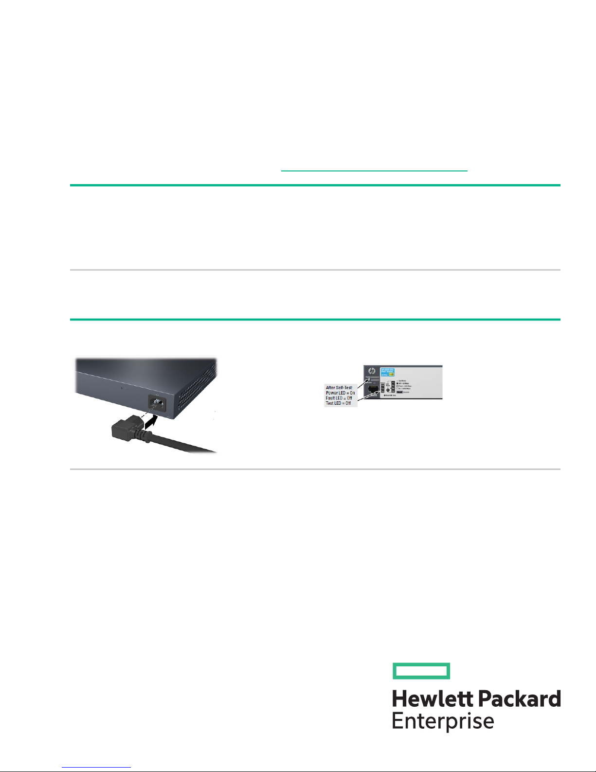
3. Power on and verify that Self-Test completes normally. The switch does not contain a power switch. It is powered on
by connecting power cord through the AC power cord
• Documentation kit
• Switch
• Console port serial cable (DB-9 to RJ-45)
• Accessory kit (installation hardware)
• AC power cord
*5900-4853*
© Copyright 2013, 2015 Hewlett Packard Enterprise Development LP
The information in this document is subject to change without notice.
Part Number: 5900-4853
Published: November 2015
Page 2
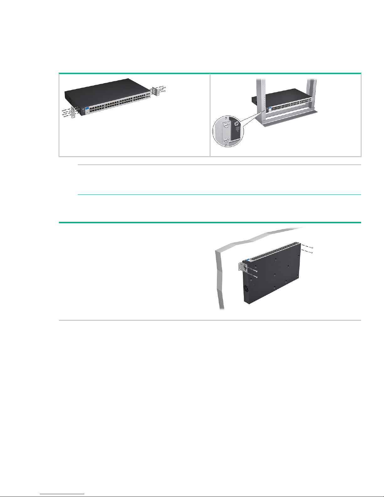
4. Install the switch hardware. Unplug the AC power from the switch before installing the switch
hardware.
Rack mounting: Use a #1 Phillips (cross-head) screwdriver to attach the accessory kit brackets to
the switch using the eight 8-mm M4 screws. Then use the four number 12-24 screws to secure the
brackets to the rack.
NOTE: The HPE 2530 24-port and 48-port switches can also be mounted in 4-post racks
and cabinets by using the HPE X410 Switch Rail Kit (J9583A). For instructions on using the
kit, see the documentation that is included with the kit.
Table or desktop mounting: Attach the four self-adhesive pads (included in the accessory kit) to
the bottom corners of the switch and place the switch on a secure horizontal surface.
Wall or Under-Table: Use a #1 Phillips (cross-head)
screwdriver to attach the supplied brackets to the switch
using the eight 8-mm M4 screws in the orientation shown.
For wall-mounting, the network ports must be facing up or
down. Do not mount the switch with ventilation or fan ducts
facing up or down. (See Installation Precautions.)
Attach the switch to the wall or wood surface with four
5/8-inch number 12 wood or tap screws (not included).
Page 3
5. Power on the switch. As shown in step 3.
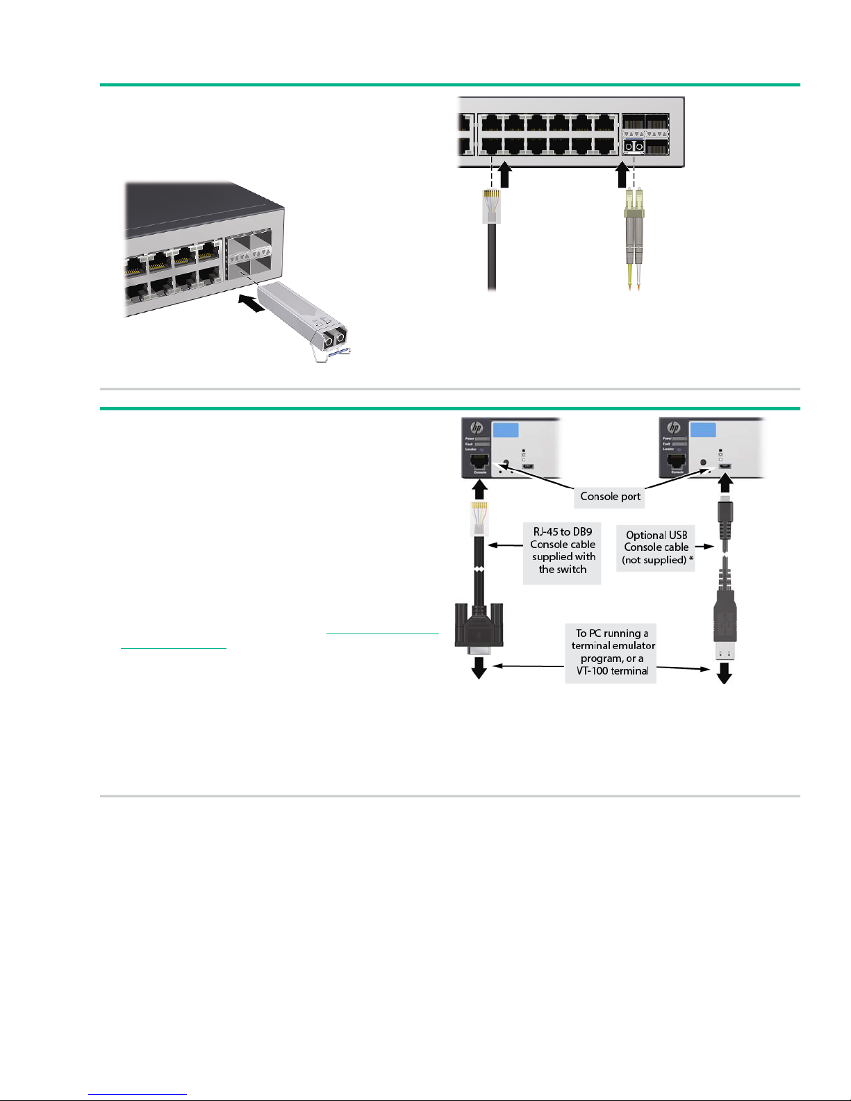
6. Connect network cables.
NOTE: For transceiver connections, install and use only
HPE SFP transceivers supported by the switch.
See “SFP Installation Notes” (page 3).
7. (Optional) Configure the switch for management.
By factory default, the switch will automatically obtain its IP
network configuration from a DHCP or BootP server.
Subsequently, you can determine the IP address assigned
to the switch by inspecting your DHCP/BootP server, or by
using LLDP from a connected device.
You can also manage and configure the switch through a
console port connection. Connect a VT-100 terminal or PC
(with suitable terminal emulation software) to the switch
using the serial cable (DB-9 and RJ-45 connectors) supplied
with the switch.
For information on configuration and remote management,
see the Management and Configuration Guide for your
switch. The manuals are available at http://www.hpe.com/
networking/support.
SFP Installation Notes
• Use only genuine Hewlett Packard Enterprise SFPs. Non Hewlett Packard Enterprise SFP
transceivers are not supported. Use of genuine Hewlett Packard Enterprise products ensures that
your network maintains optimal performance and reliability. Should you require additional transceivers,
contact a Hewlett Packard Enterprise sales representative or an authorized reseller.
• Hot swapping SFP transceivers. Supported SFP transceivers that you can install in your Hewlett
Packard Enterprise switch can be “hot swapped”–removed and installed while the switch is receiving
* You can also connect a console to the switch via the USB
console port (cable not provided). Use a USB 2.0 high-speed
cable with a male type A (4-pin) to male micro-B (5-pin)
connector. Maximum allowable length is 5m. For more
information on using the USB console port, see the Installation
and Getting Started Guide for your switch.
Page 4

power. You should disconnect the network cables from the SFP transceivers before hot-swapping
them.
When you replace an SFP transceiver with another of a different type, the switch may retain selected
port-specific configuration settings that were configured for the replaced unit. Be sure to validate or
reconfigure port settings as required.
• SFP connections to devices with fixed speed/duplex configurations. When connecting a device
to your switch port that contains an SFP transceiver, the speed and duplex settings of the switch port
and the connected device must match; otherwise, the device may not link properly — you may not
get a link. For some older network devices, including some older Hewlett Packard Enterprise devices,
the default speed/duplex settings may be predefined (for example, to 1000 Mbps/Full Duplex), or
otherwise set differently from the default configuration of your switch port. Because of these default
speed/duplex considerations, you should ensure that devices connected to your SFP ports are properly
configured. At a minimum, make sure the configurations match.
• Environmental limitations. If using SFPs with the switch, ensure that the operating temperature
range at the switch installation site does not exceed the range allowed for the SFP.
Safety and Regulatory Information for HPE 2530 24/48-Port Switches
To avoid personal injury or product damage when installing your switch, read the installation precautions
and guidelines below.
Installation Precautions
WARNING!
• The rack or cabinet should be adequately secured to prevent it from becoming unstable, tilting
or falling.
Devices installed in a rack or cabinet should be mounted as low as possible, with the heaviest
devices at the bottom and progressively lighter devices above.
• Do not wall-mount any switch without checking for restrictions in the Installation and Getting
Started Guide.
Wall-mount the switch with network ports facing up or down (away from or toward the floor).
Do not wall-mount the switch with the ventilation or fan ducts facing up or down.
Page 5

CAUTION:
• Ensure the power source circuits are properly grounded, then use the power cord supplied with
the switch to connect to the AC power source.
• If your installation requires a different power cord than the one supplied with the switch and/or
power supply, be sure the cord is adequately sized for the switch’s current requirements. In
addition, be sure to use a power cord displaying the mark of the safety agency that defines the
regulations for power cords in your country/region. The mark is your assurance that the power
cord can be used safely with the switch and power supply.
• When installing the switch, the AC outlet should be near the switch and should be easily
accessible in case the switch must be powered off.
• Ensure the switch does not overload the power circuits, wiring, and over-current protection. To
determine the possibility of overloading the supply circuits, add together the ampere ratings of
all devices installed on the same circuit as the switch and compare the total with the rating limit
for the circuit. The maximum ampere ratings are usually printed on the devices near the AC
power connectors.
• Do not install the switch in an environment where the operating ambient temperature exceeds
its specification.
• Ensure the air flow around the switch is not restricted. Leave at least 7.6 cm (3 inches) for
cooling. For the air flow direction, see the Installation and Getting Started Guide for your product,
located on the HPE Networking web site at http://www.hpe.com/networking/support.
For additional safety and regulatory information, and switch recycling information, refer to the safety and
regulatory documentation on the Hewlett Packard Enterprise website at http://www.hpe.com/support/
Safety-Compliance-EnterpriseProducts, and to the HPE 2530 Switch Installation and Getting Started
Guide that can be found on the Hewlett Packard Enterprise Networking website: http://www.hpe.com/
networking/support.
For important safety, environmental, and regulatory information, see Safety and Compliance Information
for Server, Storage, Power, Networking, and Rack Products, available at http://www.hpe.com/support/
Safety-Compliance-EnterpriseProducts.
Product Specifications
2530-24G Switch
(J9776A)
Electrical:
Acoustics:
1
Geraeusch emission
LpA=34.0 dB am
fiktiven Arbeitsplatz
nach DIN 45635 T.19
Noise Emission
LpA=34.0 dB at virtual
workspace according to
DIN 45635 T.19
2530-48G Switch
(J9775A)
Geraeusch emission
LpA=34.5 dB am fiktive
Arbeitsplatz nach DIN
45635 T.19
Noise Emission
LpA=4.5 dB at virtual
workspace according to
DIN 45635 T.19
2530-24G-PoE+ Switch
(J9773A)
3.20 A / 1.60 A1.20 A / 0.68 A0.60 A / 0.37 AMaximum current:
Geraeusch emission
LpA=43.9 dB am
fiktiven Arbeitsplatz
nach DIN 45635 T.19
Noise Emission
LpA=43.9 dB at virtual
workspace according to
DIN 45635 T.19
2530-48G-PoE+ Switch
(J9772A)
100-127 V /100-127 V /100-127 V /100-127 V /AC voltage:
200-240 V200-240 V200-240 V200-240 V
5.80-4.50 A / 2.90-2.40
A
50 / 60 Hz50 / 60 Hz50 / 60 Hz50 / 60 HzFrequency range:
Geraeusch emission
LpA=43.6 dB am fiktiven
Arbeitsplatz nach DIN
45635 T.19
Noise Emission
LpA=43.6 dB at virtual
workspace according to
DIN 45635 T.19
Page 6

Electrical:
2530-24 Switch
(J9782A)
1
2530-48 Switch
(J9781A)
2530-24-PoE+ Switch
(J9779A)
2530-48-PoE+ Switch
(J9778A)
100-127 V /100-127 V /100-127 V /100-127 V /AC voltage:
200-240 V200-240 V200-240 V200-240 V
2.80A / 1.40 A0.70 / 0.40A0.3 A / 0.2 AMaximum current:
5.20-4.10 A/ 2.60-2.20
A
50 / 60 Hz50 / 60 Hz50 / 60 Hz50 / 60 HzFrequency range:
No fanNo fanAcoustics:
Geraeusch emission
LpA=40.1 dB am
fiktiven Arbeitsplatz
nach DIN 45635 T.19
Noise Emission
LpA=40.1 dB at virtual
workspace according to
DIN 45635 T.19
1
The HPE 2530 switches automatically adjust to any voltage between 100-127 and 200-240 volts and either 50 or 60 Hz.
Geraeusch emission
LpA=43.1 dB am fiktiven
Arbeitsplatz nach DIN
45635 T.19
Noise Emission
LpA=43.1 dB at virtual
workspace according to
DIN 45635 T.19
All HPE 2530 24-Port and 48-Port Switches
Environmental:
0°C to 45°C (32°F to 113°F)Operating Temperature:
15% to 95% at 40°C (104°F) (non-condensing)Relative humidity:
-40°C to 70°C (-40°F to 158°F)Non-Operating Temperature:
15% to 90% at 65°C (149°F) (non-condensing)Non-Operating Relative humidity:
Safety:
HPE 2350 Switches:
Standards:
3.0 km (10,000 ft)Maximum Operating Altitude:
4.6 km (15,000 ft)Maximum Non-Operating Altitude:
EN60950-1:2006+A11:2009+A1:2010+A12:2011 / IEC60950-1:2005;
Am1:2009; CSA22.2 No. 60950-1-07 2nd; UL60950-1 2nd
EN 60825-1:2007 / IEC 60825-1:2007 Class 1Lasers:
Class 1 Laser Products / Laser Klasse 1
Page 7

Power Cord
Use one of the following:
Switch ModelCountry/Region
HPE 2530-24,
HPE 2530-24-POE+,
HPE 2530-24G,
HPE 2530-24G-PoE+,
HPE 2530-48,
HPE 2530-48G, and
HPE 2530-24G-PoE+ Switches
HPE 2530-48-PoE+ and
HPE 2530-48G-PoE+ Switches
8120-83758120-6869Argentina
8121-08578121-0834Australia/New Zealand
8121-11328121-1069Brazil
8120-83898120-6980Chile
8121-10348120-8377China
8120-53368120-6802Continental Europe
8120-53408120-6806Denmark
8120-53418121-0780India
8121-10098121-1035Israel
8120-53428120-6804Japan
8120-53348120-6809Malaysia
1
1
The power cord for the HPE 2530-48-PoE+ and HPE 2530-48G-PoE+ Switches supports a higher amperage and uses a C15
connector.
Japan Power Cord Warning:
Important Note for the 2530-PoE+ Switches
For PoE/PoE+ information see the HPE Power over Ethernet (PoE/PoE+) Planning and Implementation
Guide on the Hewlett Packard Enterprise website at: http://www.hpe.com/networking/support.
8120-53398120-6807Switzerland
8120-53418121-0919South Africa
8120-53368120-6811South Korea
8121-09678121-0964Taiwan
8121-06718121-0673Thailand
8120-53348120-6809United Kingdom/Hong Kong/Singapore
8121-09738120-6805United States/Canada/Mexico
Russia/Belarus/Kazakhstan/CEE Safety:
Page 8

Regulatory information
For important safety, environmental, and regulatory information, see Safety and Compliance Information
for Server, Storage, Power, Networking, and Rack Products, available at http://www.hpe.com/support/
Safety-Compliance-EnterpriseProducts.
Documentation feedback
Hewlett Packard Enterprise is committed to providing documentation that meets your needs. To help us
improve the documentation, send any errors, suggestions, or comments to Documentation Feedback
(docsfeedback@hpe.com). When submitting your feedback, include the document title, part number,
edition, and publication date located on the front cover of the document. For online help content, include
the product name, product version, help edition, and publication date located on the legal notices page.
 Loading...