

h/p/cosmos 150/50 locomotion de med, mercury, quasar, pulsar, stellar Operating Instructions And Service Manual
...
Operating instruction and service manual
h/p/cosmos running-machine-series 5.0
Running machines
h/p/cosmos mercury
h/p/cosmos mercury med
h/p/cosmos quasar
h/p/cosmos quasar med
h/p/cosmos pulsar
h/p/cosmos pulsar 3p
h/p/cosmos stellar
h/p/cosmos stellar med
h/p/cosmos stratos
h/p/cosmos stratos med
incl. lt-models
running machine
manual
Running machines
h/p/cosmos 150/50 locomotion E med
h/p/cosmos 150/50 locomotion DE med
h/p/cosmos venus - all sizes
h/p/cosmos saturn - all sizes
Manual-version
MCU5 -V1.04
Revision 20080901
manual order-no.:
[cos14310m5-v1.04hpc-en]
Development, production, sales & service
h/p/cosmos sports & medical gmbh
Am Sportplatz 8
DE 83365 Nussdorf-Traunstein
Germany
phone +49 / 86 69 / 86 42 0
fax +49 / 86 69 / 86 42 49
service@h-p-cosmos.com
www.h-p-cosmos.com
h/p/cosmos sports & medical gmbh Am Sportplatz 8 DE 83365 Nussdorf-Traunstein / Germany
phone +49 / 86 69 / 86 42 0 fax +49 / 86 69 / 86 42 49 email@h-p-cosmos.com www.h-p-cosmos.com
file: n:\article\cos14310m5-v1.04hpc-en\20080901_cos14310m5-v1.04hpc-en_manual_h-p-cosmos_running_machine.doc
© 2008 h/p/cosmos sports & medical gmbh created 01.09.2008 printed 08.10.2008 page: 1 of 176

h/p/cosmos saturn 300/125
h/p/cosmos saturn 450/300rs
This manual is only valid for the firmware-/software version noted on the first page of this manual and only for the original
configuration of the first delivery of the machine.
Firmwareupdates, softwareupdates, changes of the system configuration or retrofittings of additional equipment or
accessories can result in invalidity of this manual. In case of alterations of the device or the additional equipment always the
actual version of the manual or the according additional information has to be considered.
file: n:\article\cos14310m5-v1.04hpc-en\20080901_cos14310m5-v1.04hpc-en_manual_h-p-cosmos_running_machine.doc
© 2008 h/p/cosmos sports & medical gmbh email@h-p-cosmos.com created 01.09.2008 printed 08.10.2008 page: 2 of 176

introduction
[1.]Introduction
Dear customer,
We would like to express our gratitude for putting your trust in us, in deciding for this top of the range running machine. Since
1988 we have been developing and manufacturing running machines for sports and medical application. When it comes
down to technology, design and safety, we have set extremely high standards for ourselves.
Because the running machine is a motor-driven device, you must pay special attention to the mentioned safety regulations. If
proper notice is taken of the safety regulations, the operation of our running machines is almost without any risk. The neglect
of the safety regulations could result in dangerous situations and serious accidents. Therefore please read the installation
and operation manual and the danger precautions before taking the device into operation.
Simple maintenance, as described, can easily be done by yourself. We recommend to call our competent service team or
entering into a maintenance contract for a routine service in an interval of 6 or 12 months. A form for registration of your
institution and device is included in the delivery. In order to be able to supply you with the latest technical information and
service, it is important for you to fill out the form. Therefore please fill out the form for registration immediately and send it
back via fax.
The instruction manual as a firm part of the delivery has to be accessible for the user at any time. This instruction manual
has been written with great care. Should you, however, still find any details, which do not correspond with your device,
please give us notice, so that we can correct any mistakes as soon as possible. Subject to alterations without prior notice,
errors and omissions excepted. E & OE.
We wish you a lot of fun and success while exercising and working with your h/p/cosmos running machine.
h
Franz Harrer
President
h/p/cosmos sports & medical gmbh
© 2008 h/p/cosmos sports & medical gmbh email@h-p-cosmos.com created 01.09.2008 printed 08.10.2008 page: 3 of 176
file: n:\article\cos14310m5-v1.04hpc-en\20080901_cos14310m5-v1.04hpc-en_manual_h-p-cosmos_running_machine.doc
h/p/cosmos running machine series
introduction
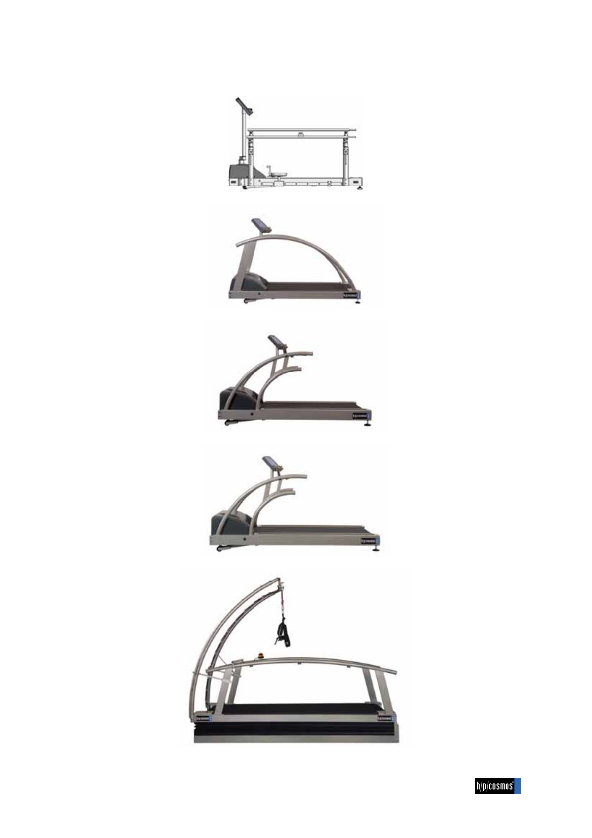
h/p/cosmos 150/50 locomotion DE med
h/p/cosmos mercury
h/p/cosmos quasar
h/p/cosmos pulsar
h/p/cosmos venus & h/p/cosmos saturn
file: n:\article\cos14310m5-v1.04hpc-en\20080901_cos14310m5-v1.04hpc-en_manual_h-p-cosmos_running_machine.doc
© 2008 h/p/cosmos sports & medical gmbh email@h-p-cosmos.com created 01.09.2008 printed 08.10.2008 page: 4 of 176

content
[2.]Content
[1.] Introduction ........................................................................................................................................................................ 3
[2.] Content ............................................................................................................................................................................... 5
[3.] Safety, warnings, precautions, prohibitions ................................................................................................................. 10
[3.A] Safety precautions, safety regulations, prohibitions and warnings ................................................................................. 10
[3.B] Exit the device in emergency case ................................................................................................................................. 11
[3.C] General Instructions / Safety .......................................................................................................................................... 11
[3.D] Instructions for safety and operation .............................................................................................................................. 12
[3.D1] Electric safety / Safety classes .......................................................................................................................... 12
[3.D2] Patient security according to VDE 0750 (IEC 601-1) type B .............................................................................. 12
[3.D3] Potential equalization ......................................................................................................................................... 12
[3.D4] Connection of units installed outside medically utilized locations ...................................................................... 13
[3.D5] Medical electrical systems ................................................................................................................................. 13
[3.D6] Subject's surroundings ....................................................................................................................................... 13
[3.D7] Protection against the danger of electrical shocks ............................................................................................. 14
[3.D8] Environmental requirements .............................................................................................................................. 14
[3.E] Economic life-time .......................................................................................................................................................... 15
[3.F] Symbols used ................................................................................................................................................................. 15
[3.G] Safety standards, norms ................................................................................................................................................ 15
[3.G1] VDE norm .......................................................................................................................................................... 16
[3.G2] The c mark ..................................................................................................................................................... 16
[3.G3] The n mark ........................................................................................................................................... 16
[3.G4] EMC Electromagnetic Compatibility ................................................................................................................... 17
[3.G5] General advice ................................................................................................................................................... 17
[3.H] Fields of application / intended use ................................................................................................................................ 17
[3.H1] Professional application in sports and fitness .................................................................................................... 17
[3.H2] Professional application in the medical field ...................................................................................................... 17
[3.H3] h/p/cosmos medical running machines - MDD medical device directive. Safety standards .............................. 18
[3.I] Forbidden use ................................................................................................................................................................ 21
[4.] Installation & commissioning ......................................................................................................................................... 22
[4.A] Transport, unpacking and packaging ............................................................................................................................. 22
[4.A1] Transport to upper or lower floors and through narrow doors ............................................................................ 22
[4.A2] Transport with trolleys ........................................................................................................................................ 24
[4.A3] Transport of oversize running machines ............................................................................................................ 24
[4.B] Mechanical installation ................................................................................................................................................... 24
[4.C] Electrical installation ....................................................................................................................................................... 26
[4.C1] Name plate ......................................................................................................................................................... 27
[4.C2] Electric safety measurements and „First Measured Values“ ............................................................................. 28
[4.C3] Potential equalization ......................................................................................................................................... 28
[4.C4] Plug assignment at the UserTerminal ................................................................................................................ 29
[4.D] Starting the running machines ........................................................................................................................................ 33
[4.D1] Unlocking of the emergency-stop switch ........................................................................................................... 33
file: n:\article\cos14310m5-v1.04hpc-en\20080901_cos14310m5-v1.04hpc-en_manual_h-p-cosmos_running_machine.doc
© 2008 h/p/cosmos sports & medical gmbh email@h-p-cosmos.com created 01.09.2008 printed 08.10.2008 page: 5 of 176

content
[4.D2] Switching the device on ..................................................................................................................................... 33
[4.D3] Switching the device off ..................................................................................................................................... 34
[4.E] Emergency-Stop / Emergency-Off ................................................................................................................................. 35
[4.F] Installation, Overview, Checklist ..................................................................................................................................... 36
[5.] Operation .......................................................................................................................................................................... 38
[5.A] UserTerminal, keyboard and display .............................................................................................................................. 38
[5.A1] The keyboard ..................................................................................................................................................... 39
[5.A2] The display ......................................................................................................................................................... 39
[5.A3] The display (standard configuration) .................................................................................................................. 40
[5.B] Mode of operation .......................................................................................................................................................... 41
[5.B1] General notes .................................................................................................................................................... 41
[5.B2] Acceleration levels ............................................................................................................................................. 41
[5.B3] Manual mode ..................................................................................................................................................... 42
[5.B4] Automatic mode ................................................................................................................................................. 43
[5.B5] Profile Mode / Pre-programmed training profiles ............................................................................................... 43
[5.B6] Possibilities of interfering into the profile mode manually .................................................................................. 45
[5.B7] Profile outline ..................................................................................................................................................... 46
[5.B8] Cardio mode – general notes ............................................................................................................................. 49
[5.B9] Cardio mode - Field of application / control ....................................................................................................... 49
[5.B10]Cardio mode – Operation ................................................................................................................................... 51
[5.B11]Possibilities of interfering with the Cardio Mode manually ................................................................................. 53
[5.B12]Test mode and free program profiles – General notes ...................................................................................... 54
[5.B13]Test profiles / Field of application ...................................................................................................................... 54
[5.B14]Test mode - Operation ....................................................................................................................................... 67
[5.B15]The UKK 2 km walk test ..................................................................................................................................... 67
[5.B16]Programing example: UKK walk test ................................................................................................................. 69
[5.B17]Programming-example: free definable profile .................................................................................................... 70
[5.B18]Possibilities of interfering in test mode manually ............................................................................................... 74
[6.] Optional settings .............................................................................................................................................................. 75
[6.A] Settings of control and display options ........................................................................................................................... 75
[6.A1] Select user options ............................................................................................................................................ 75
[6.A2] List of user options / optional functions .............................................................................................................. 76
[6.A3] Standard settings for the user options ............................................................................................................... 82
[6.B] Administrator options ...................................................................................................................................................... 83
[6.B1] List of the administrator options ......................................................................................................................... 83
[6.B2] Standard settings of administrator options ......................................................................................................... 96
[6.B3] List of running machines types .......................................................................................................................... 98
[7.] Maintenance and safety inspections ............................................................................................................................. 99
[7.A] Preventive maintenance ................................................................................................................................................. 99
[7.B] Immediate maintenance ............................................................................................................................................... 100
[7.C] Regular inspections/examinations ................................................................................................................................ 100
[7.C1] Visual inspections ............................................................................................................................................ 100
[7.C2] Protective Earth Resistance RPE measurement ............................................................................................... 101
file: n:\article\cos14310m5-v1.04hpc-en\20080901_cos14310m5-v1.04hpc-en_manual_h-p-cosmos_running_machine.doc
© 2008 h/p/cosmos sports & medical gmbh email@h-p-cosmos.com created 01.09.2008 printed 08.10.2008 page: 6 of 176

content
[7.C3] Isolation Resistance R
[7.C4] Equivalent (alternative) leakage current I
measurement .......................................................................................................... 101
ISO
measurement ............................................................................. 102
EDL
[7.C5] Leakage current measurement ........................................................................................................................ 102
[7.C6] Electric Safety Tester and measurements ....................................................................................................... 103
[7.C7] Building installation: Electric Checks, Protective Earth Function, RCD, Leakage Current .............................. 103
[7.D] Lubrication of the running belt/running surface ............................................................................................................ 104
[7.D1] Devices with UserTerminal and without automatic oil-pump ........................................................................... 104
[7.D2] Lubricant test ................................................................................................................................................... 106
[7.D3] Devices without UserTerminal and without automatic oil-pump ...................................................................... 107
[7.D4] Devices with UserTerminal & automatic oil-pump (models "r" for cycle & wheelchair) .................................... 108
[7.D5] Set back of oil message MCU 4 without UserTerminal .................................................................................... 110
[7.D6] Set back of oil message MCU with UserTerminal ............................................................................................ 110
[7.E] Control and tightening of the running belt .................................................................................................................... 111
[7.F] Adjustment (centering) of the running belt ................................................................................................................... 112
[7.G] Control and tightening of the driving belt ...................................................................................................................... 113
[7.G1] Driving belt with poly-V-belt system ................................................................................................................. 113
[7.G2] Driving belt with timing-belt system .................................................................................................................. 115
[7.H] Side step platforms: Check for non-slipping ................................................................................................................. 115
[7.I] Hygiene, cleansing, cleansing of the interior ................................................................................................................ 115
[7.J] Cleansing and adjustment of the speed-sensor/Light-barrier ....................................................................................... 116
[7.K] Cleansing and adjustment of the light-barrier at belt-re-entry-zones ........................................................................... 117
[8.] Trouble shooting ............................................................................................................................................................ 118
[8.A] Mechanical / Noise problems ....................................................................................................................................... 118
[8.B] Running belt adjustment problems ............................................................................................................................... 118
[8.C] Fuses ............................................................................................................................................................................ 118
[8.D] Interference factor ........................................................................................................................................................ 119
[8.D1] Electrostatic Discharge .................................................................................................................................... 119
[8.D2] Source of Interference ..................................................................................................................................... 119
[8.E] Voltage at the device housing / electric shock ............................................................................................................. 120
[8.E1] Open (interrupted) earth wire / ground ............................................................................................................. 120
[8.F] Malfunctions of the heart rate measurement system POLAR ...................................................................................... 120
[8.F1] Troubleshooting heart rate measurement system POLAR .............................................................................. 121
[8.G] Malfunctions of the RS232 interface ............................................................................................................................ 121
[8.G1] Troubleshooting and testing of the RS232 interface ........................................................................................ 121
[8.H] Malfunctions of the control unit ..................................................................................................................................... 121
[8.I] Error messages / Error codes ...................................................................................................................................... 122
[8.I1] Devices with UserTerminal .............................................................................................................................. 122
[8.I2] Devices without UserTerminal ......................................................................................................................... 127
[8.J] Set back of error message ........................................................................................................................................... 127
[8.J1] Devices with UserTerminal .............................................................................................................................. 127
[8.J2] Devices without UserTerminal ......................................................................................................................... 127
[9.] Technical data ................................................................................................................................................................ 128
[9.A] Running machines ........................................................................................................................................................ 128
[9.B] EMC electromagnetic compatibility. Guidance and manufacturer's declaration ........................................................... 132
file: n:\article\cos14310m5-v1.04hpc-en\20080901_cos14310m5-v1.04hpc-en_manual_h-p-cosmos_running_machine.doc
© 2008 h/p/cosmos sports & medical gmbh email@h-p-cosmos.com created 01.09.2008 printed 08.10.2008 page: 7 of 176

content
[9.C] Compatibility RS232 interface / USB converter ............................................................................................................ 134
[10.] Accessories and options ............................................................................................................................................ 135
[10.A]Arm support for body weight support and safety .......................................................................................................... 135
[10.A1]Danger precaution and operation of the adjustable arm supports ................................................................... 135
[10.A2]Reproducibility of adjustments ......................................................................................................................... 136
[10.B]Additional keyboard and add. stop-button for arm support and remote control............................................................ 136
[10.C]Handrails adjustable with gear tooth locking elements ................................................................................................ 137
[10.C1]Danger precaution and operation .................................................................................................................... 138
[10.C2]Reproducibility of adjustments ......................................................................................................................... 138
[10.D]Handrails adjustable. Parallel bars with gas struts and locking lever ........................................................................... 139
[10.D1]Safety precautions and operation .................................................................................................................... 139
[10.D2]Adjustment of the bar handrails ....................................................................................................................... 140
[10.D3]Reproducibility of adjustments ......................................................................................................................... 141
[10.E]Therapist’s seat and foot support adjustable ................................................................................................................ 141
[10.E1]Safety precautions and operation .................................................................................................................... 141
[10.E2]Operation and adjustment ................................................................................................................................ 142
[10.F]Special handrails .......................................................................................................................................................... 143
[10.G]h/p/cosmos airwalk se 135 (available as of 10/2008) ................................................................................................... 144
[10.H]Unweighting system h/p/cosmos airwalk ...................................................................................................................... 145
[10.H1]Vests for subjects for h/p/cosmos airwalk ........................................................................................................ 145
[10.I] Wheelchair ramp .......................................................................................................................................................... 146
[10.J]h/p/cosmos wheel chair stabilizer for oversize running machines ................................................................................ 146
[10.K]Safety arch with chest belt and harness ....................................................................................................................... 147
[10.L]Running belt rotation reversible for downhill walk ........................................................................................................ 148
[10.L1]Ripcord with magnet switch ............................................................................................................................. 148
[10.L2]Change from forward to reverse rotation ......................................................................................................... 148
[10.L3]Change from reverse to forward rotation ......................................................................................................... 149
[10.M]Bottle holder ................................................................................................................................................................. 149
[10.N]Retrofitting UserTerminal ............................................................................................................................................. 149
[10.O]Monitor / laptop arm ..................................................................................................................................................... 149
[10.P]Safety multiple socket .................................................................................................................................................. 150
[10.Q]Digital (serial) RS232 interface / USB converter .......................................................................................................... 150
[10.Q1]Interface cable RS232 for connection to PC .................................................................................................... 151
[10.Q2]Interface cable RS232 for connection to ECG Schiller .................................................................................... 151
[10.Q3]Interface cable RS232 for connection to Ergospirometrie JAEGER / VIASYS / Cardinal Health OXYCON .... 151
[10.R]Printer protocol ............................................................................................................................................................. 152
[10.S]POLAR Heart rate measurement system ..................................................................................................................... 153
[10.S1]Note from POLAR for patients with pacemaker ............................................................................................... 153
[10.S2]Chest belt and transmitter ................................................................................................................................ 153
[10.S3]Radius of transmission ..................................................................................................................................... 153
[10.S4]Battery of the transmitter .................................................................................................................................. 154
[10.S5]Correct placement of transmitter belt ............................................................................................................... 154
[10.S6]Transmission problems .................................................................................................................................... 154
[10.T]PC Software h/p/cosmos para control 4.0® .................................................................................................................. 154
[10.U]PC Software h/p/cosmos para graphics® ..................................................................................................................... 156
[10.V]PC Software h/p/cosmos para analysis® ...................................................................................................................... 157
file: n:\article\cos14310m5-v1.04hpc-en\20080901_cos14310m5-v1.04hpc-en_manual_h-p-cosmos_running_machine.doc
© 2008 h/p/cosmos sports & medical gmbh email@h-p-cosmos.com created 01.09.2008 printed 08.10.2008 page: 8 of 176

content
[10.W]PC Software h/p/cosmos para motion ......................................................................................................................... 158
[11.] Certificates ................................................................................................................................................................... 159
[11.A]Certificate of the TSA (TÜV) according to ISO 9001-2000 ........................................................................................... 159
[11.B]Certificate of the TSA (TÜV) according to EN ISO 13485-2003 ................................................................................... 160
[11.C]EC Certificate of the TSA (TÜV) ................................................................................................................................... 161
[11.D]Certificate of compliance for sports and fitness devices .............................................................................................. 162
[11.E]Certificate of compliance medical devices ................................................................................................................... 163
[12.] Disposal ........................................................................................................................................................................ 164
[12.A]Disassemble and cut up ............................................................................................................................................... 164
[12.B]h/p/cosmos running machine ....................................................................................................................................... 164
[12.C]h/p/cosmos service oil / grease .................................................................................................................................... 164
[12.D]h/p/cosmos running belt ............................................................................................................................................... 164
[13.] Contact .......................................................................................................................................................................... 165
[13.A]Service department ...................................................................................................................................................... 165
[13.B]Sales department ......................................................................................................................................................... 165
[13.C]Headquaters ................................................................................................................................................................. 165
[14.] Appendix – Instruction and commissioning ............................................................................................................. 166
[14.A]Instruction into general operation ................................................................................................................................. 166
[14.B]Instruction into functions ............................................................................................................................................... 167
[14.C]Instruction into maintenance works .............................................................................................................................. 169
[14.D]Advice and support documents .................................................................................................................................... 170
[14.E]Confirmation of commissioning and introduction / instruction ...................................................................................... 171
[14.F]Service report – cos15531 ........................................................................................................................................... 172
[14.G]Control protocol – cos15533 ........................................................................................................................................ 173
[14.H]Wiring diagram load circuit quasar med 5.0 / pulsar 5.0 .............................................................................................. 174
[14.I] Wiring diagram control circuit quasar med 5.0 / pulsar 5.0 – page 1 ........................................................................... 175
[14.J]Wiring diagram control circuit quasar med 5.0 / pulsar 5.0 – page 2 ........................................................................... 176
file: n:\article\cos14310m5-v1.04hpc-en\20080901_cos14310m5-v1.04hpc-en_manual_h-p-cosmos_running_machine.doc
© 2008 h/p/cosmos sports & medical gmbh email@h-p-cosmos.com created 01.09.2008 printed 08.10.2008 page: 9 of 176

safety, warnings, precautions, prohibitions
[3.]Safety, warnings, precautions, prohibitions
[3.A] Safety precautions, safety regulations, prohibitions and warnings
N Use the running machine and accessories only under supervision of your doctor or/and trainer. Using the running
machine and the accessories without supervisory staff and introduction is forbidden.
N Before using the running machine, read the operation manual, safety precautions and safety regulations carefully.
N Start with slow walking. After some minutes increase the speed slowly according to your fitness level.
N It is strongly recommended to visit a doctor before using a sports device.
N Do not jump onto the rotating running belt. Do not jump off the rotating running belt (not even towards the front).
Do not stop moving or turn around on the rotating running belt. Never run sideways or backwards. Do not do
anything which could interfere with your balance. Do not set too high loads (speed, elevation).
N Always train with sports or running shoes (no spikes) - never run barefoot - and sports clothing.
N At the time of use the emergency-stop has to be in reach for the subject and the supervisory staff at any time.
N Use emergency-stop only if in danger or in danger of falling.
N At set elevation (e.g. by pressing the stop-button or the emergency-off-button, power failure, etc.), the bodyweight
of the subject and the force of gravity may cause an acceleration of the running belt. Do not step on the slant of
roller when getting on or off the running surface; the gravity force might cause a movement of the running belt.
N Dangerous capture areas/gaps at the elevation system as well as at the rear end and the sides of the running belt.
(At reverse belt rotation: danger as well at the motor hood and the front area).
N Please make sure that, in case of a fall, subjects with long hair, wide clothes, jewellery, etc. do not get caught in
the capture area at the rear end of the running belt. Possibly use a hairnet and make the subject aware of the
danger or secure the person with a safety harness against fall. Do not deposit any clothes, towels, jewellery, etc.
on the running machine – because of danger of tripping over and danger of capturing.
N Children and animals are not allowed to use the running machine and must not get too near (4 m distance) to it.
N Using the running machine under the influence of alcohol, drugs and/or anesthetic is prohibited.
N Interrupt the training immediately if you start feeling sick, dizzy or pain and see your doctor.
N Improper or excessive training or strain by tests may cause serious health injury or even death.
N Subjects with a cardiac pacemaker or those who suffers from any kind of physical restriction must see their doctor
and get a permission before using the running machine.
N The subject has to be secured by a safety arch with fall stop an chest belt while performing sprints, max.
endurance test and while training on wide running surfaces and/or other higher dangers.
N Please keep a safety area of at least 2 m in length and 1 m width directly behind the running machine. For running
machines equipped with reverse-belt-rotation keep a safety area of 2 m in length and 1 m width in the front and the
back of the running machine and always use the pull-rope emergency-stop or better the chest belt with fall-stop.
N Explicit warning of improper and forbidden use.
N Ensure that all cables (power connection, interface, potential equalization, etc.) and accessories are installed
properly and safely and that nobody can stumble or fall over the cables and/or accessories.
N Pay attention to further safety regulations and operation instructions in the appendix of this instruction manual. Pay
special attention to all maintenance and service instructions (also in manuals of accessories).
N
In case of any detected and/or assumed malfunctions and/or defects or unreadable safety warning labels the
device has to be taken out of operation, the device has to be marked and secured against operation and the
supplier and authorized service personnel has to be informed in writing.
N Disregard of warnings, disregard of intended and forbidden use, safety precautions and also unauthorized or lack
of maintenance and/or regular safety checks may lead to injuries or death and/or can damage the device and will
result in loss of any liability and warranty.
N Do not drink and eat any lubrication material and no other material or parts of this device, and keep all lubrication
material and all other parts away from children and animals.
N These safety precautions and regulations are to be displayed within sight of the running machine. The warnings,
safety regulations and dangers have to be pointed out to every user and operator. The manufacturer does not
undertake any liability for any injury to persons or damage to property.
N Valuable articles (like watches, emblazonments, etc.) must be abated before using the device and must also not
be in near environment of the device.
file: n:\article\cos14310m5-v1.04hpc-en\20080901_cos14310m5-v1.04hpc-en_manual_h-p-cosmos_running_machine.doc
© 2008 h/p/cosmos sports & medical gmbh email@h-p-cosmos.com created 01.09.2008 printed 08.10.2008 page: 10 of 176

safety, warnings, precautions, prohibitions
[3.B] Exit the device in emergency case
In any emergency case (e.g. danger of stumbling and/or falling, etc.) the emergency button has to be pressed instantly!
Hold the side rails and/or the front rail with both hands and step on the footrest (step-platforms) with both feet.
[3.C] General Instructions / Safety
This instruction manual is part of the device and must always be accessible for every user.
Exact observance of the instruction manual is a requirement for the appropriate operation of an h/p/cosmos device.
Holding the handrails during exercise may effect the exercise results (e.g. heart rate, ECG, oxygen uptake, etc.). Under
normal conditions and for healthy subjects we recommend to hold the handrails only for emergency or when needed for
safety or unweighting.
Important notes, warnings and safety precautions are marked with the opposite sign. It also
reminds you of concerns which have to be considered for measurements and connection with
other devices.
The safety of your subjects and the compliance to the mentioned accuracy of measurement can only be achieved, if the
consumption goods, sensors and detectors, described in the instruction manual, are being used and the recommended
preventive maintenance and safety checks are performed by personnel authorised by h/p/cosmos.
Absorption-, cleansing- and disinfecting chemicals are only to be kept in the appropriate reservoirs. At the connection of
gas pressure container it has to be examined about its MOT-admissibility (TÜV) first. Pull the plug before cleansing or
disinfecting electric devices.
Safety, reliability and function can only be achieved if ...
N installation, extension, alteration and repair is performed by authorized people.
N the room for installation corresponds to the DIN and VDE installation directives.
N the device is plugged in at a socket with a protection system.
N the room for installation corresponds to the requirements of the surroundings for the device.
N the device after the instruction is being used in accordance with the instruction manual.
The entry of fluid into the device has to be removed immediately by the authorized customer service and a safety
examination has to be performed. Damaged socket connections, wires and pressure control switches have to be
replaced instantly by trained personnel or by authorised persons.
In case of any detected and/or assumed malfunctions and/or defects or unreadable safety warning
labels the device has to be taken out of operation, the device has to be marked and secured
against operation (for example pull power plug and affix warning/defect label on the power plug)
and the supplier and authorised service personnel has to be informed in writing.
file: n:\article\cos14310m5-v1.04hpc-en\20080901_cos14310m5-v1.04hpc-en_manual_h-p-cosmos_running_machine.doc
© 2008 h/p/cosmos sports & medical gmbh email@h-p-cosmos.com created 01.09.2008 printed 08.10.2008 page: 11 of 176

safety, warnings, precautions, prohibitions
[3.D] Instructions for safety and operation
The regulations mentioned in this chapter refer to the Federal Republic of Germany. For all other states take into
account the national legislation. If the running machine is a sports device (only c mark without 4-digit number), it must
not be connected with a medical product and must not be used for medical purposes. Due to higher safety requirements
medical instruments and devices are not allowed to be connected via extension cable and/or multiple plug socket with
the power supply, and a medical product must not be connected with a sports device either.
Disregard of warnings, disregard of intended and forbidden use, safety precautions and also
unauthorized or lack of maintenance and/or regular safety checks may lead to injuries or even
death and/or can damage the device and will result in loss of any liability and warranty
[3.D1] Electric safety / Safety classes
In order to protect the subject (athlete and/or patient) and the personnel, the association of German electrotechnicians Inc, (VDE) has published special directives for medical used rooms and electro-medical devices.
Devices with a power supply therefore have to, in order to prevent the passing on of the mains voltage over to
touchable metal pieces, be equipped with not only a reliable isolation of the parts being under voltage but also
additional safety precautions. The VDE-association divides it into so called safety classes.
Of the, for electro-medical devices, licensed safety classes are mainly used the safety class I (i.e. safety
precautions with protective wiring), and the safety class II, (i.e. safety measures without protective wiring but with
double isolation): Devices of the safety class I are devices, where the metallic casing-parts are connected with the
protective wire of the line net via the safety contact. In the case of an isolation error the inserted fuse element
switches off.
[3.D2] Patient security according to VDE 0750 (IEC 601-1) type B
If your h/p/cosmos device has a c mark with a 4-digit number (e.g. n) at the identification plate, it is a
medical product. At your h/p/cosmos medical product the patient is protected/isolated from the mains in
accordance with the safety standard referring to the requirements for leakage current values according to IEC 6011 type B. The connection of further mains-operated units to your h/p/cosmos-unit may cause that all the leakage
currents add and the safety of the patient is reduced. Due to this the connection of further units may only be
carried out on consultation with h/p/cosmos.
[3.D3] Potential equalization
The connection of e.g. EDP units to the V24 / RS 232 / USB / LAN / FireWire interface of the computer or of other
independent measuring stations can only be carried out in medically utilized locations according to VDE 0107 / EN
ISO 60601-1-1. Parallel connection of the potential equalization ensures, that in case of insulation failure none of
the connected units exceeds a voltage of 10mV and thus endangers the patient.
For this purpose all of the h/p/cosmos units are equipped with a connection fixture with which the equipotent
conductor, being part of the standard equipment, is connected to the equipotent bus bar of the room.
Standard potential equalization cable (length 5m) with 4mm
2
cross-section [cos10223]
file: n:\article\cos14310m5-v1.04hpc-en\20080901_cos14310m5-v1.04hpc-en_manual_h-p-cosmos_running_machine.doc
© 2008 h/p/cosmos sports & medical gmbh email@h-p-cosmos.com created 01.09.2008 printed 08.10.2008 page: 12 of 176

safety, warnings, precautions, prohibitions
[3.D4] Connection of units installed outside medically utilized locations
If units installed outside medically utilized locations (e. g. external printer, host computer etc.) are connected to an
h/p/cosmos unit installed in a medically utilized location the VDE 0750 regulations must be observed. Connection
only via …
1. Optical fibre or optocoupler (4 kV checked and approved) or …
2. Protective isolation via insulation transformer according to IEC 601-1, appendix k. These units are to be
connected to the equipotent conductor.
Due to the increased safety requirements medical instruments may not be connected via extension leads or multiway connectors.
[3.D5] Medical electrical systems
The medical electrical system (later in this text referred as “system”) is a combination of several devices, of which
at least one is a medical electrical equipment. A combination occurs when devices are connected via so called
“functional connections” or via a mobile multiple socket. Not only electrical connections are defined as “functional
connections” but also those for the transmission of signals, electrical energy and/or substances. Thus already the
operation of two or more devices on the same multiple outlet is defined as a system. Even a mechanical
connection or a wireless connection produces a medical electrical system.
Basically it is imperative that a system is as safe as a single medical electrical equipment. The requirements in the
medical devices act and the applicable regulations (for example MPBetreibV) must be met. The system as a whole
must ensure that within the patients environment or at contact with patients the same level of safety prevails, as
determined by DIN EN 60601-1 (VDE 0750 Part 1).
[3.D6] Subject's surroundings
The surroundings of the subject must
have a gap of 1.5 m as it has been
proofed by experience. This has been
laid down here as the surrounding.
file: n:\article\cos14310m5-v1.04hpc-en\20080901_cos14310m5-v1.04hpc-en_manual_h-p-cosmos_running_machine.doc
© 2008 h/p/cosmos sports & medical gmbh email@h-p-cosmos.com created 01.09.2008 printed 08.10.2008 page: 13 of 176

[3.D7] Protection against the danger of electrical shocks
Casing and cover: Parts of non-medical
electric devices within the surrounding of
the subject, which, after having taken off
the coverings etc. without the use of tools
for a routine maintenance etc., are in
touchable reach, have to operate with a
voltage that does not exceed 25 volt
alternate voltage and 60 volt direct
voltage, which is produced by a separate
source as described in IEC 601-1.
According to this example the leakage
current would flow from the electric device
to the earthened subject via the trainer/doctor.
Electrical equipment [3] and a subject [1] must never be touched by the doctor or trainer [2]
at the same time.
[3.D8] Environmental requirements
safety, warnings, precautions, prohibitions
Running machines are not to be used in medically utilized rooms with a danger of explosions or in easily
inflammable atmospheres. The devices must not be installed near to e.g. an x-ray device, motors or transformer
with high connection power, as the electric and magnetic interference can falsify measurements or even make
them impossible. High voltage lines must be avoided nearby the device. h/p/cosmos electrical devices with mains
connections must neither be used in wet and humid areas (e.g. swimming pool, sauna, etc.) nor in environmental
chambers.
If not stated otherwise in the delivery information h/p/cosmos devices are designed for operation in normal climatic
surroundings (DIN IEC 601-1):
N Temperature: + 10° ... + 40° C
N Relative humidity: 30 ... 70 % (non condensing!)
N Air pressure: 700 ... 1060 mbar
N Maximum operating altitude: approx. 10,000 feet (3000m), without pressurization
The running machine has to be protected from high humidity. Venting slots are not to be covered; otherwise it
would hinder the air circulation. Store the devices at a temperature of – 20° ... + 50° C.
All devices can be stored without power-connection and without operation for a period of 6 – 9 months. After this
period batteries in the device may be discharged and maintenance and/or a new setup/programming of the device
could required by authorized h/p/cosmos technician.
file: n:\article\cos14310m5-v1.04hpc-en\20080901_cos14310m5-v1.04hpc-en_manual_h-p-cosmos_running_machine.doc
© 2008 h/p/cosmos sports & medical gmbh email@h-p-cosmos.com created 01.09.2008 printed 08.10.2008 page: 14 of 176

safety, warnings, precautions, prohibitions
T
[3.E] Economic life-time
The economic life time of the product is determined at common usage and application to 20 years, provided that after 10
years all electrical parts and component are renewed (at damage or unusual heavy duty possibly earlier) and the
recommended maintenance intervals are kept. Every maintenance and repair work needs to be carried out by
authorized h/p/cosmos technicians. For expendable parts a shorter life-time is due.
[3.F] Symbols used
All symbols used comply with the according norms IEC417, IEC878, EN957-1:2005 and Council Directive 2002/96/EC.
Read manufacturer’s guide, advises,
instructions and manual
Warning / safety precautions
Pay attention to accompanying instructions
R
J
[3.G] Safety standards, norms
All h/p/cosmos running-machines are produced according to strict safety- and quality controls. The running machine
must not be used, if the certificates/permissions and the (according to the list of technical specifications) defined safety
standards do not correspond with the local and country-specific requirements. The country-specific requirements must
be compared before initial operation. Operate running machine only, if the requirements correspond. Full list of
applicable norms see also in the CE-certificate of compliance.
The standards with date in this manual with reference to design and construction characteristics, refer to the up to date
valid versions at the time of manufacture.
The standards with date in this manual applying to routine measurements and continual safety relevant measures (e.g.
electrical measurements to determine leakage current, insulation resistances etc.) can and will change with time.
Therefore the up to date valid versions of the respective standards at the time of measurement and their limit values,
which can deviate then from the procedures and limit values in this manual, apply.
Devices of the type B
Dangerous electric voltage
Alternating current (AC)
M
N
P
Protection ground
Earth
Potential compensation
Symbol for collection, treatment, recycling
and disposal of waste electrical and
electronic equipment (WEEE) as set out in
Directive 2002/96/EC of 27 January 2003
of the European Parliament and of the
Council on waste electrical and electronic
equipment are necessary to reduce the
waste management problems linked to the
heavy metals concerned and the flame
retardants concerned.
file: n:\article\cos14310m5-v1.04hpc-en\20080901_cos14310m5-v1.04hpc-en_manual_h-p-cosmos_running_machine.doc
© 2008 h/p/cosmos sports & medical gmbh email@h-p-cosmos.com created 01.09.2008 printed 08.10.2008 page: 15 of 176

safety, warnings, precautions, prohibitions
[3.G1] VDE norm
The running-machines for the professional application in sports and fitness have been built corresponding to the
DIN EN 60335-1 (VDE 0700) guidelines. The running-machines for the professional application in the medical area
have been built corresponding to the DIN EN 60601-1 (VDE 0750) guidelines.
[3.G2] The c mark
The c mark on the nameplate of the sports and fitness running machines confirms the compliance to the council
directive 89/336/EEC appendix I (EMC electromagnetic compatibility). The audit has been conducted after the
criterion of jamming and interference immunity.
[3.G3] The n mark
The n mark on the nameplate of the running machine for medical application confirms the compliance to
the council directive 93/42/EEC (MDD Medical-Device-Directive).
file: n:\article\cos14310m5-v1.04hpc-en\20080901_cos14310m5-v1.04hpc-en_manual_h-p-cosmos_running_machine.doc
© 2008 h/p/cosmos sports & medical gmbh email@h-p-cosmos.com created 01.09.2008 printed 08.10.2008 page: 16 of 176

safety, warnings, precautions, prohibitions
[3.G4] EMC Electromagnetic Compatibility
The running-machines for the professional application in sports and fitness (with c mark) have been built
corresponding to the European Union Council Directive 89/336/EEC (EMC) and the low voltage directive
73/23/EEC. Norms: EMC: EN55011; EN61000-6-1; EN61000-3-2; EN61000-3-3, Safety: EN60950
The running-machines for medical applications (with n mark) have been built corresponding to the
European Union Council Directive 93/42/EEC
Norms: EMC: EN60601-1-2; EN61000-3-2; EN61000-3-3, Safety: EN60601-1
Certification bodies: Mitsubishi Electric Europe / EMC-Laboratroy, Mündelheimer Weg 35, DE 40472 Düsseldorf
EMV Testhaus GmbH, Gustav - Hertz - Strasse 35, DE 94315 Straubing / Germany, J. Schmitz GmbH, 83022
Rosenheim
Strong electromagnetic fields, transmitters and interferences, which are above the normal tolerance, can interfere
with measuring fuctions and displays of the running machines and can lead to other malfunctions.
Follow details to EMC values, guidance and manufacturers declaration in this manual in chapter „technical data“
[3.G5] General advice
The device is assigned to overvoltage-category II and pollution level I.
[3.H] Fields of application / intended use
All running-machines are built corresponding to the classes S and A based on EN 957-1:2005 / EN 957-6:2001.
[3.H1] Professional application in sports and fitness
The running machine models designed for sports and fitness have not been tested for application in medical areas
and therefore are not qualified for that field of application. They must not be connected to other medical devices.
You can apply these models in endurance training walking and running.
[3.H2] Professional application in the medical field
The running machine models designed for professional application in the medical field are also qualified for sports
and fitness use as well as for application in the medical field.
N Endurance training walking and running
N Endurance tests and EMG-measuring with the subject in the laboratory (only with safety arch / fall stop)
N Ergometry on the Running-Machine, Exercise- ECG and Ergospirometrie (only with safety arch / fall stop)
N Gait training
N Recreational fitness training
Children are only allowed to use the running machine under constant supervision of a
medical doctor and only when safeguarded by safety harness with fall-stop. Additionally
h/p/cosmos suggests the use of adjustable handrails.
file: n:\article\cos14310m5-v1.04hpc-en\20080901_cos14310m5-v1.04hpc-en_manual_h-p-cosmos_running_machine.doc
© 2008 h/p/cosmos sports & medical gmbh email@h-p-cosmos.com created 01.09.2008 printed 08.10.2008 page: 17 of 176

safety, warnings, precautions, prohibitions
[3.H3] h/p/cosmos medical running machines - MDD medical device directive. Safety standards
Over 20 years of experience in the production of treadmill-ergometers and complex systems with accessories and
special options have made h/p/cosmos the absolute treadmill specialist. We consider ourselves as the “market
precursor in technology and safety” amongst all treadmill manufacturers. Safety has a very high priority for us –
above all because we know from experience what kind of accidents can occur and which consequences might
result from these accidents.
On the one hand a treadmill is a very effective instrument in rehabilitation, therapy and diagnostics. However, like
in many areas of daily life (i.e. all kinds of traffic, may it be by car, train or bus or the handling of electrical machine
tools etc.) the use of a treadmill involves dangers which can be minimized by abiding strictly to safety procedures,
but can never be fully ruled out. As a manufacturer it is h/p/cosmos’ duty, and as the distributor or enduser/operator of the running machine it is your duty, to minimize those dangers as far as possible.
In medical applications many additional risks (patients with pacemakers, ECG lead and electrode connections to
the skin, health and physical limitations, high workloads during stress tests, medication, etc.) have to be
considered. Therefore medical treadmills with interface and interactive heart rate based load controls are classified
as risk class IIb medical devices. They have specific additional design characteristics compared to fitness
treadmills, and can only be sold and serviced by authorized and certified distributors. h/p/cosmos has the
responsibility to ensure that the systems are correctly installed (with usage instruction) and maintained. Therefore
we have implemented a medical device observation and reporting system based on the statutory obligations
contained in, Guideline 93/42 EEC, MDD (medical device directive), ISO9001 and EN13485 standard and our
internal safety policy and risk management system. This is of utmost importance and all our distributors must sign
a contract that they will comply with these important international rules for medical devices, particularly for class IIb
devices and their respective statutory requirements.
h/p/cosmos fulfils its duty in different ways:
N All medical treadmill-ergometer device-families have to undergo an internal product-type examination as well
as external tests performed by the respective examination institutes such as the TUV Product Service in
Munich / Germany or the EMC laboratory. Our medical treadmill-ergometers meet the norms and guidelines
stipulated for medical applications such as the, MDD, EU guideline 93/42 EEC for medical products, IEC EN
60601-1 (VDE 0750), VDE 0751, IEC EN 60601-1-2 (EMC), IEC EN 60601-1-4, EN 957-1, EN 957-6.
N All h/p/cosmos medical treadmill-ergometers must undergo a 24-hour non-stop test after production with strict
safety tests, high-voltage-tests and electrical as well as mechanical safetychecks. All tests are recorded,
checked by a second independent employee and filed. h/p/cosmos treadmills have to pass the checks 100%
without exception.
N All medical h/p/cosmos treadmill-ergometers have an Emergency Off Switch (current off with mains
disconnection, not only the “standard software controlled emergency stop button”), power supply with
increased voltage resistance, electrical installation and wiring according to IEC 60601-1, a potential
equalization pin and a potential equalization transformer.
N h/p/cosmos has a quality management and risk management system according to ISO 9001:2000 & ISO
13485:2003 as well as medical device observation and incident reporting system.
file: n:\article\cos14310m5-v1.04hpc-en\20080901_cos14310m5-v1.04hpc-en_manual_h-p-cosmos_running_machine.doc
© 2008 h/p/cosmos sports & medical gmbh email@h-p-cosmos.com created 01.09.2008 printed 08.10.2008 page: 18 of 176

safety, warnings, precautions, prohibitions
N In the course of maintenance work h/p/cosmos technicians or authorised service personnel check the
electrical safety of the treadmill together with all safety relevant details and measure the accuracy of speed
and elevation of the treadmills at the customer’s premises.
N h/p/cosmos trains all relevant service technicians and sales personnel as medical device consultants with
respective certification.
N The user manuals of h/p/cosmos treadmills contain all important information and safety advice as well as
maintenance instructions and user regulations. The treadmills have a label with the date of the next safety
check /maintenance.
N h/p/cosmos offers numerous options and accessories such a safety arch with harness for fall prevention,
chest belt with automatic stop, arm supports or the unweighting system h/p/cosmos airwalk, which increase
safety for the patient during the use of a treadmill-ergometer. http://www.h-p-cosmos.com/en/safety/index.htm
All running machines and other machines with moving belts and parts, hold a great potential of danger at the belt
re-entry zones on the sides and at the end of the running surface, as the gap between running belt and frame is
frequently too wide. To reduce the risk for users, h/p/cosmos running machines have a gap of less than 4 mm and
it is marked clearly with additional danger precaution stickers.
Therefore we take it as our responsibility to inform our partners and customers about the background and
necessity only to use medical products in the medical application field. Statutory requirements only permit us to
supply medically classified equipment for medical applications.
Medical Device Directive Article 1 Definitions, scope 2 a.)
“medical device” means any instrument, apparatus, appliance, material or other article, whether used alone or in
combination, including the software necessary for its proper application intended by the manufacturer to be used
for human beings for the purpose of: Diagnosis, prevention, monitoring, treatment or alleviation of disease,
diagnosis, monitoring, treatment, alleviation of or compensation for any injury or handicap, investigation,
replacement or modification of the anatomy or of a physiological process, control of conception, and which does
not achieve its principal intended action in or on the human body by pharmacological, immunological or metabolic
means, but which may be assisted in its function by such means;
file: n:\article\cos14310m5-v1.04hpc-en\20080901_cos14310m5-v1.04hpc-en_manual_h-p-cosmos_running_machine.doc
© 2008 h/p/cosmos sports & medical gmbh email@h-p-cosmos.com created 01.09.2008 printed 08.10.2008 page: 19 of 176

safety, warnings, precautions, prohibitions
The use of a product not released for medical use by the manufacturer in a medical application can result in
increased risks for the patients and for the operator – especially in the case of an accident on the treadmill
ergometer. In this case all parties involved (your insurance company, your professional association, possibly
patients lawyers and courts) will question negligence and liability. Therefore the use of a sports device for medical
purposes bears increased risks for the distributor, customer, operator, end user and last but not least the patient.
Despite that some of the above mentioned laws and guidelines are only binding within the European Union, the
patient’s needs, the risks and the required safety procedures are the same all over the world. We ask all parties
involved to help in improving safety.
Some examples for safety features at h/p/cosmos devices:
Potential isolation
Opto coupler board Potential equalization
transformer
Medical devices are equipped with an Emergency-OffButton instead of a conventional Safety-Stop-Button,
which disconnects the device from the power supply when
pushing the button in emergency cases. Sport devices
mostly are only equipped with an emercency-stop-button,
which only stops the machine but does not disconnet it
completely from the mains.
Shielded motor
connector
cable
Frequency inverter metal housing (for shielding)
Danger zone sticker
file: n:\article\cos14310m5-v1.04hpc-en\20080901_cos14310m5-v1.04hpc-en_manual_h-p-cosmos_running_machine.doc
© 2008 h/p/cosmos sports & medical gmbh email@h-p-cosmos.com created 01.09.2008 printed 08.10.2008 page: 20 of 176

safety, warnings, precautions, prohibitions
[3.I] Forbidden use
N All prohibitions in the chapter "safety precautions, safety regulations, prohibition and warnings"
N The running machine must not be used without being carefully instructed by specialist staff and without having
received notes on the safety regulations.
N Interrupt the training immediately if you start feeling sick or dizzy and see your doctor.
N Subject with a cardiac pacemaker or who suffers from any kind of physical restriction must see a doctor before
using the running machine and ask for allowance.
N Children and animals are not allowed to use the running machine and must not get near (4m safety area) to it.
N Other use, then explicitly listed directed use at the point field of application.
N In case of any detected and/or assumed malfunctions and/or defects or unreadable safety warning labels the
device has to be taken out of operation, the device has to be marked and secured against operation and the
supplier and authorized service personnel has to be informed in writing.
N Every kind of overload of test person / subject / patient is forbidden.
N Every kind of use with increased risk, e.g. sprint or medical application with patients and increased risk of falling, is
forbidden without using additional safety precautions and safety equipment, such as e.g. safety-arch with fall-stop.
N In case of existence of one or more of the following contraindications we strongly suggests to see a medical doctor
or a specialist before using the running machine: pregnancy, acute thrombosis, heart- and/or arteries disease,
fresh wounds e.g. after surgery, artificial joints and limbs, acute fracture, damaged disc or traumatic caused
disease of the spine, diabetes, epilepsy, inflammations, acute migraine and any kind of tumors. Please contact the
manufacturer h/p/cosmos, if your doctor or specialist needs further information about the running machine.
N The automatic operation (modes profile, cardio, test, remote control via PC and peripheral devices) is forbidden, if
the health and condition of the test person / subject / patient does not allow it and if a doctor has not authorized it.
Disregard may cause injuries and dangerous health problems and even death.
N All use with wheels (cycling, wheelchair, inline-skating or roller-ski) is forbidden at standard running surfaces and -
belts. Such applications are only allowed at special running machines marked with „r“(e.g. h/p/cosmos saturn
300/100r). Additionally a safety harness with fall-stop is prescribed. The brakes at the bike respectively wheelchair
must be deactivated (e.g. demount brake suspension) and the stop at the inline-skates must be demounted during
the exercise on the running machine. Do not forget to reactivate brakes before using this equipment outdoor again.
N Never use running shoes or other shoes with spikes or studs at the standard running surface resp. running belt.
These applications are only allowed on special running machines with suffix „rs“ which have as an option
additionally an extra thick running belt. A safety arch with chest belt and fall-stop is also obligatory in this case.
N In environmental conditions, others than specified in the chapter „technical specifications“ and “environmental
conditions“, h/p/cosmos devices must not be used (e.g. in wet and humid areas, swimming pools, sauna,
environmental chambers, high-pressure-, low-pressure, altitude- and oxygen-chambers, etc.).
At the suspicion of unauthorized access or other reasons to lock the running machine, it has to be
locked for starting: See „option 40“ in chapter „option settings“. With option 41 ... 44 you can lock
also separate modes (manual, profile, cardio, test).
file: n:\article\cos14310m5-v1.04hpc-en\20080901_cos14310m5-v1.04hpc-en_manual_h-p-cosmos_running_machine.doc
© 2008 h/p/cosmos sports & medical gmbh email@h-p-cosmos.com created 01.09.2008 printed 08.10.2008 page: 21 of 176

installation & commissioning
[4.]Installation & commissioning
[4.A] Transport, unpacking and packaging
When receiving the machine in a crate or unpacked, make sure the machine, the accessories and/or the packaging is
not damaged. If you discover any damage and/or missing parts make a note on the packing-list / delivery note of the
carrier. Inform h/p/cosmos and your dealer immediately in writing about any damages and/or missing parts.
The manufacturer does not undertake any liability for any damage, complaints and missing parts
which is not reported immediately by delivery on the packing-list / delivery note.
Before you unpack the machine and accessories read instructions on the crate. Make sure that the machine, power
connection cable or any optional equipment will not be damaged during unpacking. Pay special attention on small parts,
so that you do not dispose them or any instructions with the packaging. Within Germany mostly all devices are delivered
and assembled by h/p/cosmos directly or by an authorised forwarder. If delivered by h/p/cosmos the packaging will be
taken back and recycled.
If the running machine is being delivered by a carrier, you can recycle the packaging yourself or send it back to the
manufacturer (transportation is to be paid by the customer). Often a recyclable transport tool or packaging or a
transport-fuse (metal angle with screws) is included in the extent of delivery.
Ask your dealer and the carrier to take the packaging and the recyclable transport tool back to your dealer or to
h/p/cosmos at your own costs. In some cases a credit note can be granted. Special packaging and/or carrier
constructions must not be disposed unauthorized.
[4.A1] Transport to upper or lower floors and through narrow doors
With the standard models (sizes running surface 150/50cm, 170/65cm, 190/65cm / except adjustable handrails)
the handrail at the left is easy to remove, as there are no cables inside. The handrail at the right can be
unscrewed, can be put 90° to the left ("lay it on the running belt") and then the handrail has to be temporarily fixed
with special transport fuse construction (available at h/p/cosmos) in order to avoid damages during the transport.
Under the condition that the right handrail lies flat and
temporarily fixed on the running surface, the whole
machine can be put 90° to the right to an upright
position. So the width of the machine is fairly reduced
and can be easily moved through narrow doors or
windows.
A special transport tool is available to move the
machine through aisles - see below (available as loan
object at h/p/cosmos).
file: n:\article\cos14310m5-v1.04hpc-en\20080901_cos14310m5-v1.04hpc-en_manual_h-p-cosmos_running_machine.doc
© 2008 h/p/cosmos sports & medical gmbh email@h-p-cosmos.com created 01.09.2008 printed 08.10.2008 page: 22 of 176

installation & commissioning
Transport angle construction running surface 150/50cm [cos10971]
Transport angle construction running surfaces 170 and 190/65cm [cos10314]
Transport angle construction running surface 200 ... 300/75 ... 125cm [cos14090]
Transport tool for construction size running surface 150/50cm [cos10972]
Transport tool for construction size running surfaces 170 and 190/65cm [cos13794]
file: n:\article\cos14310m5-v1.04hpc-en\20080901_cos14310m5-v1.04hpc-en_manual_h-p-cosmos_running_machine.doc
© 2008 h/p/cosmos sports & medical gmbh email@h-p-cosmos.com created 01.09.2008 printed 08.10.2008 page: 23 of 176

installation & commissioning
[4.A2] Transport with trolleys
For an easy transport put 2 usual trolleys under the device (platform
approximately 30cm x 30cm with 4 maneuverable rolls each) to make the
device “mobile”.
Trolley with 4 rolls for max. 300kg [cos13016]
Trolley with 4 rolls for max. 500kg [cos13672]
[4.A3] Transport of oversize running machines
For big devices it might be the best and only possibility to move them through the window with the help of a special
basket and a heavy mobile crane.
Transports of heavy devices must only be carried out by authorised staff in compliance with
the safety standards. Otherwise there is serious danger for people and devices.
[4.B] Mechanical installation
N In order to ensure proper installation and safety, either the manufacturer, an authorised service crew or an
authorised dealer must always perform transport and installation of the devices
N For reasons of safety please make sure that there is a safety zone of at least L: 2.5m x W: 1.0m behind and
L: 1.0m x B: 1.0m to the front the running machine. Please note, that with the optional equipment reversible
running belt rotation you also have to ensure a safety zone of L: 2.5m x W: 1.0m in front of the running machine.
N Put an aerobic mat (or something similar) in front of and behind the running machine to protect the subject when
falling. Put the device on a rubber mat as large as the device to protect the floor from dust and scratches, to
ensure a firm stand and to reduce noise.
N The provided space for the running machine must be even and horizontal.
N Models with leveling sockets (adjustable "feet") at the rear of the running machine have to be adjusted so that they
have a firm stand, otherwise it could lead to noises like knocking or rattling during the training. Check the weight
load pressure on the leveling sockets (weight of the running machine at the rear), by trying to lift the frame off the
ground at the rear of the running machine one side after the other. That way you can find out, whether you have
got the same load on the two sockets. The levelling sockets and the front wheels of the elevation system may
cause a print in the flooring. In case of sensitive flooring please use h/p/cosmos floor mats for protection:
Floor protection mat 150/50 for running machines with deck size 150x50 cm [cos14005]
Floor protection mat 170/65 for running machines with deck size 170x65 cm [cos14042]
Floor protection mat 190/65 for running machines with deck size 190x65 cm [cos14043]
file: n:\article\cos14310m5-v1.04hpc-en\20080901_cos14310m5-v1.04hpc-en_manual_h-p-cosmos_running_machine.doc
© 2008 h/p/cosmos sports & medical gmbh email@h-p-cosmos.com created 01.09.2008 printed 08.10.2008 page: 24 of 176

installation & commissioning
Other sizes available on request.
N For models without leveling sockets please make sure that the floor condition is even and horizontal. The machine
stands with the entire ground frame on the floor.
N Models with a running surface of 200 x 75 cm or bigger: Make sure the floor condition is even and horizontal. The
machine stands with the entire ground frame on the floor. There are leveling sockets incorporated, but they should
only be used in case of problems with and uneven floor.
N Before you switch on the device you need to de-install the mechanical transportation fuse, fixing the upper and
lower frame.
N The bearing capacity of floor and ceiling in the building must be higher than the weight of the machine. It has to be
approved for the h/p/cosmos device by an authorized body of the operator. Example h/p/cosmos saturn 4.0
300/100r: Dimensions ground frame running machine: L: 3400 mm x B: 1490 mm = 5.066 m² platform. Net weight
of running machine: 1300 kg, static bodyweight of subject: 200 kg, dynamical weight of subject: 1200 kg (up to 6
times the bodyweight), over all weight load of system at platform: 2500 kg = bearing capacity of platform: 493.48
kg (~ 500 kg) / m².
N At h/p/cosmos gaitway with integrated force plate the transportation locks have to be removed after erection. Drive
elevation up to max of 25 %. Loosen the four M8 screws, indicated with the red arrows at the underside of the aluforce plates and remove them. Drive elevation down to 0 %. Loosen the locknuts at the levelling sockets. Now
level out the running machine with the help of the Kistler Software and then tighten the locknuts again.
N The running belt has to be checked and if necessary adjusted (see maintenance instructions), so that it is placed
exactly in the middle of the two rollers, after installation or change of location.
N If the running machine is installed safely and horizontal, it can be plugged in (see installation instructions) and
taken into operation.
N It is recommended to lubricate the running surface with 40ml Silicone-Oil before using it for the first time. See
separate chapter "maintenance".
file: n:\article\cos14310m5-v1.04hpc-en\20080901_cos14310m5-v1.04hpc-en_manual_h-p-cosmos_running_machine.doc
© 2008 h/p/cosmos sports & medical gmbh email@h-p-cosmos.com created 01.09.2008 printed 08.10.2008 page: 25 of 176

installation & commissioning
[4.C] Electrical installation
An overload or an voltage drop (even short-time) of more than 20 % of the mains voltage might
cause malfunctions and/or defects and might totally switch-off the running machine. At such high
voltage drops or at total power failure the running machine switches off and the running belt stops.
To start again you have to switch-on the running machine at the main „ON“ switch and than press
START at the keyboard.
N Installation of any electrical device and h/p/cosmos running-machines must only be carried out at a voltage power
connection with ground wire (earthing) including leakage-current protection-switch (interrupter) and according to
VDE 0100 or/and the currently valid regulations and directives. Requirements for special locations, areas and
establishments (e.g. medically used areas) must be strictly adhered. PE-connection (protection-earth-contact) is
stipulated at all running-machines. The voltage drop between the beginning of the consumer’s installation and the
wall socket must not be more than 4% (DIN VDE 0100-520). It is the consignee’s and user’s personal responsibility
to check the correct functions of the mains connection including the outlets and an authorized electrical engineer
must check these points for perfect functions regularly (1 ... 4 years). Inspections of the electrical installations
within the building are not incumbent on the supplier h/p/cosmos.
N Read the nameplate of the machine before connecting the machine to the power outlet, just in case the machine
was designed for special voltage supply (e.g. 110 Volts and 25 Ampere). As standard, a usual power supply of
230 Volt / AC, 50/60 Hz is sufficient for most of the running machines.
N The bigger running machines (size running surface 190/65cm 3p up to 300/125cm)
require a 3 phase AC power supply: 3 x 400 Volt / 32 Amp (running machine
190/65cm 3p 16 Amp) fused (read name of the machine just to make sure) and righthanded polarized (clockwise rotation field).
Pictures power-plug (on device) and power-outlet:
CEE power outlet (socket), 5-pin, 16 Ampere
[cos11092]
CEE power outlet (socket), 5-pin, 32 Ampere
[cos11090]
Power supply for h/p/cosmos pulsar 3p
400 Volt AC 3~/N/PE f: 50/60 Hz Imax: 16.0 A
3 phase current with clockwise rotation field.
16 Ampere fuse (C-characteristic)
The plug-in has 5 plugs:
L1 = Phase 1 (black wire)
L2 = Phase 2 (brown wire)
L3 = Phase 3 (black or grey wire)
N = Neutral (blue wire)
PE = Ground / Earth (yellow-green wire)
The mentioned wire colours are applicable for Germany and different colours may be applicable in other countries.
Voltage values for 3-phase voltage power supply:
from L1 to L2: 400 Volt, from L1 to L3: 400 Volt, from L2 to L3: 400 Volt
from L1 to N: 230 Volt, from L2 to N: 230 Volt, from L3 to N: 230 Volt,
Power supply for h/p/cosmos venus and saturn
400 Volt AC 3~/N/PE f: 50/60 Hz Imax: 32.0 A
3 phase current with clockwise rotation field.
32 Ampere fuse (C-characteristic)
The plug-in has 5 plugs:
L1 = Phase 1 (black wire)
L2 = Phase 2 (brown wire)
L3 = Phase 3 (black or grey wire)
N = Neutral (blue wire)
PE = Ground / Earth (yellow-green wire)
file: n:\article\cos14310m5-v1.04hpc-en\20080901_cos14310m5-v1.04hpc-en_manual_h-p-cosmos_running_machine.doc
© 2008 h/p/cosmos sports & medical gmbh email@h-p-cosmos.com created 01.09.2008 printed 08.10.2008 page: 26 of 176

installation & commissioning
N After having switched on a 3 phase machine, an elevation of 0 % has to be adjusted automatically. If this is not the
case, the unit is to be switched off immediately and the two phases of the wall socket have to be changed so that
the device is supplied with right-handed polarized power. Otherwise the elevation cannot be set correctly and the
power supply of the motor for controlling the elevation is switched off via the limit stop switch at the ground frame.
N Use a usual 16 Ampere expulsion fuse with C-tripping-circuit for your house distribution. For running machine-
models with a construction size of the running surface of 200/75cm up to 300/125cm you will need a 32 Ampere
expulsion fuse with C-tripping-circuit. If however, the expulsion fuses switch off when starting the device, the circuit
has to be secured with a blowout fuse or an expulsion fuse with another tripping-circuit (e.g.: K–fuse). Read name
plate and technical data of the machine just to make sure.
N For further questions please ask your electrical engineer or h/p/cosmos.
N Before installing the running machine please compare the specifications on the nameplate concerning the mains
voltage and the mains frequency with your local characteristics. Connection only if identical.
N Check the main lead, the voltage power supply outlet and ground wire protection-contacts before plugging it in.
Damaged leads and couplers and defective or dirty contacts have to be exchanged immediately. Rubber-leads can
get porous and friable after some years.
[4.C1] Name plate
Name plate examples sports device model h/p/cosmos quasar / medical device h/p/cosmos saturn 300/125r
For full details please refer to the chapter „technical data“ in this manual.
N Plug the running machines directly into the wall socket. Each running machine has to be
connected to a separate circuit. The socket has to be marked with name and serial number of
the running machine. The use of an extension cables or a multiple plug sockets is not
allowed.
N Electrical devices with mains connections must neither be used in wet and humid areas (e.g.
swimming pool, sauna, etc.) nor in environmental chambers.
file: n:\article\cos14310m5-v1.04hpc-en\20080901_cos14310m5-v1.04hpc-en_manual_h-p-cosmos_running_machine.doc
© 2008 h/p/cosmos sports & medical gmbh email@h-p-cosmos.com created 01.09.2008 printed 08.10.2008 page: 27 of 176

[4.C2] Electric safety measurements and „First Measured Values“
Immediately at first installation at the customer’s site an electric safety test
and measurement has to be performed for „Protective Earth Resistance“,
„Isolation Resistance“ and „Leakage Current“ and the values have to be
recorded on a special protocol [cos11690xx] and marked with „first
measured values“. For details please refer to the chapter „maintenance /
inspections“ in this manual. One copy of this protocol [cos11690xx]
remains at the owner’s manual and the original of the protocol with the
„first measured values“ shall be sent to the manufacturer h/p/cosmos.
Picture: Example for electric safety testing device based on IEC 601-1
[4.C3] Potential equalization
The potential equalization cable [cos10223] must be connected with the
connector on the device plug and with the potential-compensationbearing within the medically used room. During installation, connecting or
disconnecting the potential equalization, the device (running machine)
must not be connected to the power supply. Protection against electric
shock has to be provided in the finished product/device.
N When used in the medical field, all devices within the system have to be connected via a
potential-compensation-cable in „star-connection“ with the potential-compensationbearing within the medically used room.
N First connect the potential compensation (potential equalization) with the corresponding
plug pin (next to the main switch at the front) and then connect the mains plug.
N During electric safety measurements and test (leakage currents, etc.) the potential
equalization cable has to be disconnected temporarily.
installation & commissioning
file: n:\article\cos14310m5-v1.04hpc-en\20080901_cos14310m5-v1.04hpc-en_manual_h-p-cosmos_running_machine.doc
© 2008 h/p/cosmos sports & medical gmbh email@h-p-cosmos.com created 01.09.2008 printed 08.10.2008 page: 28 of 176

installation & commissioning
[4.C4] Plug assignment at the UserTerminal
If the UserTerminal was disassembled during transport please connect the cables according to following
illustration:
N Devices with MCU5 control unit (as of manufacturing date 12/2007)
file: n:\article\cos14310m5-v1.04hpc-en\20080901_cos14310m5-v1.04hpc-en_manual_h-p-cosmos_running_machine.doc
© 2008 h/p/cosmos sports & medical gmbh email@h-p-cosmos.com created 01.09.2008 printed 08.10.2008 page: 29 of 176

installation & commissioning
N Devices with MCU4 control unit (until manufacturing date 12/2007)
file: n:\article\cos14310m5-v1.04hpc-en\20080901_cos14310m5-v1.04hpc-en_manual_h-p-cosmos_running_machine.doc
© 2008 h/p/cosmos sports & medical gmbh email@h-p-cosmos.com created 01.09.2008 printed 08.10.2008 page: 30 of 176

installation & commissioning
N For devices with MCU4 control unit (until manufacturing date 12/2007) and reverse belt rotation
file: n:\article\cos14310m5-v1.04hpc-en\20080901_cos14310m5-v1.04hpc-en_manual_h-p-cosmos_running_machine.doc
© 2008 h/p/cosmos sports & medical gmbh email@h-p-cosmos.com created 01.09.2008 printed 08.10.2008 page: 31 of 176

Picture top:
MCU5-control-board and display board inside the UserTerminal
Picture right
Sticker for plug references at the back plate of the UserTerminal
installation & commissioning
Above: Drawing cable connection for ON/OFF button and emergency stop in
the UserTerminal
Right hand side: Ground connection at the UserTerminal
Note: GND / GND = ground
file: n:\article\cos14310m5-v1.04hpc-en\20080901_cos14310m5-v1.04hpc-en_manual_h-p-cosmos_running_machine.doc
© 2008 h/p/cosmos sports & medical gmbh email@h-p-cosmos.com created 01.09.2008 printed 08.10.2008 page: 32 of 176

[4.D] Starting the running machines
[4.D1] Unlocking of the emergency-stop switch
In order to be able to switch on the device, you may have to unlock the Emergency-stop switch first by pulling it
(depending on the type) or turning it around (to the left hand side, see symbol).
[4.D2] Switching the device on
If the running machine is at an angle of elevation > 0 when switching it on, it will
automatically drive into the position zero (display: ELEVATION „INIT“). So please take care
before switching on, that while driving down the elevation no harm can be done to persons
and there are no objects under the running machine.
No. Illustration Description
installation & commissioning
[01]
[02]
Release all emergency stop buttons of the treadmill-ergometer.
picture left unlatching by turning
picture below unlatching by pulling
The expulsion fuse at the front of the device (front terminal below
the hood) has to be switched on.
[03]
Switch on the running machine by using the white key (until 2003
green "ON" or "I" key). at the FrontTerminal. At some models built
before the year 12/2007 the location of the ON-/OFF-key could
also be the UserTerminal.
The indicator light within the key is glowing (if the indicator does
not flash up, please check the power supply, the expulsion fuse
and the Emergency-stop).
file: n:\article\cos14310m5-v1.04hpc-en\20080901_cos14310m5-v1.04hpc-en_manual_h-p-cosmos_running_machine.doc
© 2008 h/p/cosmos sports & medical gmbh email@h-p-cosmos.com created 01.09.2008 printed 08.10.2008 page: 33 of 176

installation & commissioning
Devices for Sports and Fitness manufacturing before manufacturing date 12/2007
The running machine can be switched on directly at the expulsion fuse at the FrontTerminal (frontal section below
the hood) to the condition "stand-by mode" (if the emergency-stop has been activated a flashing notice „PULL
STOP“ appears on the display.).
Expulsion fuse and
main switch 2- or 3-pole
ON / OFF button
with control lamp
ON / OFF button
until 2003
Main switch from construction
size running surface
200...300/75...125cm onwards
[4.D3] Switching the device off
N The ON-/OFF-intervals must not be shorter than 1-2 minutes (at models with 3-phase
connection: 2-3 minutes). Otherwise it could lead to interference in the adjustment of
the motor or to the failure of the backup.
N The models for medical application with the isolation transformer have an inrush-
current limiter (surge guard). Too short switch on / switch off intervals will lead to a
deactivation of the inrush current limiter and results in an overload of the circuit fuse.
N For the professional use, where the devices are often being used daily, we recommend
to switch on the devices in the morning, and leave it in the stand-by mode during the
day.
Switch off the running machine by pressing the black key (until 2003 red “O” key) at the UserTerminal (some
models at the front of the device). The indicator within the key is extinguished. At some models built before
12/2007 the location of the ON-/OFF-key could also be the UserTerminal.
Devices for Sports and Fitness manufacturing before 12/2007
The machine can be switched off directly with the explusion fuse at the FrontTerminal (frontal section below the
hood).
file: n:\article\cos14310m5-v1.04hpc-en\20080901_cos14310m5-v1.04hpc-en_manual_h-p-cosmos_running_machine.doc
© 2008 h/p/cosmos sports & medical gmbh email@h-p-cosmos.com created 01.09.2008 printed 08.10.2008 page: 34 of 176

[4.E] Emergency-Stop / Emergency-Off
installation & commissioning
When in danger of falling or in any
emergency case please press the
red button of the emergency-stop
picture left unlatching by turning
picture below unlatching by pulling
at the UserTerminal. At devices
without UserTerminal the red
emergency-stop-button is located
directly at the handrail.
In order to switch on the device
again, unlock the Emergency-stop
by pulling or by turning it slightly
to the left (depending on the
type).
Running machines for sports and fitness with manufacturing date before 12/2007 will be ready for operation immediately
(pay attention to the display). Running machines with manufacturing date after 12/2007 resp. all treadmills for medical
application (independet of manufacturing date) have to be switched on with the white „I“ key (until 2003 green “ON” or “I”
key) again. Before switching it on again, however, wait for at least 1 to 2 minutes (3 phase devices: 2 to 3 minutes). As
mentioned above „Switching the device off“.
N Use the emergency-stop only if in danger.
N The emergency-stop is not to be used as a normal stop-key.
file: n:\article\cos14310m5-v1.04hpc-en\20080901_cos14310m5-v1.04hpc-en_manual_h-p-cosmos_running_machine.doc
© 2008 h/p/cosmos sports & medical gmbh email@h-p-cosmos.com created 01.09.2008 printed 08.10.2008 page: 35 of 176

installation & commissioning
[4.F] Installation, Overview, Checklist
The authorized technician (distributor or service partner) has to check whether the installation of the device has been
performed properly, before the customer is introduced into the operation of the h/p/cosmos device. For detailed
information and instructions for installation and commissioning please refer to all respective individual chapters in this
manual. Among others, following points save to be performed or controlled:
No. Illustration
Description
[01]
[02]
[03]
Compare the delivery note with the installed running machine.
Are all parts like running machine, accessories, service box and
running machine folder complete and without damage.
Adjust the levelling sockets.
Tighten all fixation screws of the handrails.
accomplished
accomplished
accomplished
[04]
Check the wall socket: Optical check for damages, burned
contacts, proper fixation and good ground contact (no paint, dirt,
deformation)
Check out the correct pin assignment of the wall socket with a
socket-tester with direct indication (see picture left).
As testing-device we recommend the Testavit Schuki 3 –
[cos15900] - Separate instruction available at h/p/cosmos.
Check the electrical connection of the device: Direct connection to
the wall socket with separate fuse, no danger of stumbling, no
extension cable, no multiple plug socket, separate circuit for the
treadmill. If a correct connection to the wall socket is not possible,
note this on the delivery note, inform the customer and put the
device out of operation (if necessary) and safe
against start-up.
file: n:\article\cos14310m5-v1.04hpc-en\20080901_cos14310m5-v1.04hpc-en_manual_h-p-cosmos_running_machine.doc
© 2008 h/p/cosmos sports & medical gmbh email@h-p-cosmos.com created 01.09.2008 printed 08.10.2008 page: 36 of 176
accomplished

installation & commissioning
[05]
[06]
[07]
Immediately at first installation an electric safety test / measurment
has to be performed for „Protective Earth Resistance“, „Isolation
Resistance“ and „Leakage Current“ and the values have to be
recorded on a special protocol [cos11690xx] and marked with „first
measured values“. For details please refer to chapter
„maintenance / inspections“. One copy of this protocol
[cos11690xx] remains at the owner’s manual and the original with
the „first measured values“ shall be sent to h/p/cosmos. The
potential equalization cable has to be
connected AFTER the measurements.
Lubricate the running machine before introduction according to
instruction with 30 ml special silicon oil which is part of the “service
box”.
Check the tension of the running belt (no slip).
accomplished
accomplished
accomplished
[08]
Adjust the running belt properly before instruction with the
customer.
The allen-key must be pulled out of the screw
immediately after usage due to risk of injury!
accomplished
[09]
Test the function of the heart rate transmission with the help of a
simulator or a POLAR sender. Search for interferences and
possible reasons.
file: n:\article\cos14310m5-v1.04hpc-en\20080901_cos14310m5-v1.04hpc-en_manual_h-p-cosmos_running_machine.doc
© 2008 h/p/cosmos sports & medical gmbh email@h-p-cosmos.com created 01.09.2008 printed 08.10.2008 page: 37 of 176
accomplished

[5.]Operation
[5.A] UserTerminal, keyboard and display
If your running machine has no UserTerminal (no display, no keyboard), it can only
be controlled via interface RS 232, e.g. via ECG, Ergospirometry, PC with software
h/p/cosmos para graphics
®
or h/p/cosmos para control®. Important security advices,
warnings, system requirements and a list of the compatible peripheric devices you
can find in this manual under RS232 interface and option functions RS232 protocol
or at our homepage www.coscom.org
More recent computers will have only an USB interface instead of the RS232 interface. For that case an „USB to RS232
interface-adapter-cable“ is available at h/p/cosmos under order number cos12769. To control via USB interface the
processor must be a Pentium 1.8 GHz or higher.
To use all the functions described below and for maintenance and service we recommend the PC software h/p/cosmos
para control
®
(Freeware). It is possible to purchase a keyboard or an external UserTerminal as optional equipment for
these models, which can be connected to the running machine via interface RS232. Option 1: UserTerminal MCU4
remote control with 5 meter cable: h/p/cosmos order number cos10002. Option 2: additional keyboard 6 keys with 2
meter cable: h/p/cosmos order number [cos10106]. When using an additional keyboard it is necessary (depending on
the model) to install a additional wiring and a connector, or the UserTerminal backplate has to be re-fitted/removed.
At the suspicion of unauthorized access or other reasons to lock the running machine, it has to be
locked for starting: See „option 40“ in chapter „option settings“. With option 41 ... 44 you can lock
also separate modes (manual, profile, cardio, test).
Oversize running machines and devices without UserTerminal
The oversize running machines series
h/p/cosmos venus and h/p/cosmos
saturn have an external control unit
with integrated UserTerminal.
It is possible to re-fit lt-models and to
equpip oversize running machines with
an additional UserTerminal at the
handrail.
pic. top: Retrofitting UserTerminal at handrail
pic. left: External control unit with options:
rolls set and monitor-/laptop arm
Attachment for retrofitting UserTerminal at handrail [cos13514]
Monitor arm (movable-) for PC monitors or laptops [cos13321]
Laptop computer [cos13476]
Roll set (4 rolls) for external control unit [cos14184]
operation
file: n:\article\cos14310m5-v1.04hpc-en\20080901_cos14310m5-v1.04hpc-en_manual_h-p-cosmos_running_machine.doc
© 2008 h/p/cosmos sports & medical gmbh email@h-p-cosmos.com created 01.09.2008 printed 08.10.2008 page: 38 of 176

[5.A1] The keyboard
g
Do not lean on the UserTerminal. Do not put any pressure on the display. Press the keys softly. As
confirmation you will hear a beeping sound.
operation
Basic functions
Alteration of elevation
ram steps
Pro
Modus-Übernahme (Manual, Profile, Cardio, Test)
Basic functions
Selection of mode (manual, profile, cardio, test)
Alteration of parameters (speed, acceleration / deceleration)
Selection of options, program parameter
Basic functions
Stop
Discontinuance of operation
Basic functions
Confirmation of mode (manual, profile, cardio, test)
Confirmation of parameter (speed, time, pulse, a.s.)
Confirmation of options (measuring unit)
Start (of selected mode)
Modification of acceleration / deceleration
The keys may also have special functions within different modes. See the instructions manual mode, profile mode, cardio
mode and test mode
[5.A2] The display
The display consists of 6 four digit LCD-displays, which show speed, exercise period, (energy consumption,
wattage and MET by turns), exercise distance, elevation (inclination) and heart rate. Next to the LCD-displays you
will find light-emitting diodes (LED) in addition, which supply information about mode, measuring unit and so on.
Flashing displays indicate:
N select option (LED ~)
N alterable parameter (LCD)
N interference / error
file: n:\article\cos14310m5-v1.04hpc-en\20080901_cos14310m5-v1.04hpc-en_manual_h-p-cosmos_running_machine.doc
© 2008 h/p/cosmos sports & medical gmbh email@h-p-cosmos.com created 01.09.2008 printed 08.10.2008 page: 39 of 176

The indicated values remain, after stopping the running machine, until ...
... the running machine has been started again with the
c -key
... the mode (manual, profile, cardio, test) has been changed
operation
... the display has been initiated by pressing the
If the running machine has been stopped by reducing the speed with the
display continues with the previous values after starting again.
[5.A3] The display (standard configuration)
Speed
LED Status Unit Definition
max
m/min
km/h
m/s
mph
Running distance
{
{
~
{
{
m/min
km/h
m/s
mph
0.1
0.01
0.01
0.01
b -key once more.
a -key („PAUSE“-position), then the
Display LED Status Unit Definition
{
~
{
MET
KJ
Watt
Index
hh:mm 1 1
0.1
1
1
1
MET *
Energy consumption
Wattage
Fitness-Index (UKK)
* One metabolic equivalent (MET) is defined as the consumption of oxygen
while sedentary life. Two MET correspond to the consumption while walking
with ca. 3.5 km/h and 8 MET correspond to the consumption while running
with ca. 13 km/h. Displayed not for all models.
MET
Energy
Power
Runing time
LED Status Unit Definition
mm:ss
LED Status Unit Definition
~
{
{
m
km
miles
0.1
0.1
0.1
m
km
miles
Elevation
Program sequence (Step) / -number (No)
LED Status Unit Definition
%
Step
No
~
{
{
{
%
°
0.1
0.1
1
1
~ LED on / { LED off
Display LED Status Unit Definition
Heart rate (max.)
Heart rate (min.)
Sex
Age
Weight
Height of subject
Ï
Ð
Sex
M = male
F = female
Age
Weight
H ....
{
{
{
{
{
1/min
1/min
M/F
year
kg
cm
1
1
1
1
1
file: n:\article\cos14310m5-v1.04hpc-en\20080901_cos14310m5-v1.04hpc-en_manual_h-p-cosmos_running_machine.doc
© 2008 h/p/cosmos sports & medical gmbh email@h-p-cosmos.com created 01.09.2008 printed 08.10.2008 page: 40 of 176

[5.B] Mode of operation
[5.B1] General notes
The running machine is equipped with 4 modes of operation: manual, profile, cardio and test. Some of the modes
of operation can also be changed online into another while the running machine is in operation.
Select the Mode first (see 4 LED) with a or d and confirm the Mode with c
The incorporated series interface is always active. This means, that you can send and receive data/commands at
any time (parallel) and during any mode. Always the latest command will be executed. No matter if the command
came via interface or from the UserTerminal during one of the 4 modes.
[5.B2] Acceleration levels
7 different acceleration levels and deceleration levels are available for all modes and for remote control via
interface and h/p/cosmos coscom protocol. Max. acceleration level and minimum acceleration level see chapter:
User options / optional functions. The following diagram shows the acceleration levels at a running machine with
maximum speed of 40km/h.
operation
Explanation: [a] Speed in km/h, [b] Time in seconds
0 to maximum speed: Intensity [1] 131 sec., [2] 66 sec., [3] 33 sec., [4] 16 sec., [5] 8 sec., [6] 5 sec. and [7] 3 sec.
Never set too high loads (speed, acceleration, elevation). High loads are forbidden, if the
health and the condition of the test person / patient do not allow them and a doctor has not
authorized these loads. Disregard may cause injuries and dangerous health problems. At
high loads and identifiable risks meet the appropriate higher and reasonable safety
precautions.
file: n:\article\cos14310m5-v1.04hpc-en\20080901_cos14310m5-v1.04hpc-en_manual_h-p-cosmos_running_machine.doc
© 2008 h/p/cosmos sports & medical gmbh email@h-p-cosmos.com created 01.09.2008 printed 08.10.2008 page: 41 of 176

[5.B3] Manual mode
Initiation: Running belt is not moving. One of the modes LED ~is flashing: (manual, profile, cardio, test)
Step no. Activity Keys Response / Display
[5.B3]
[01] Select operational mode manual
a or d
Alteration of the mode (manual, profile, cardio, test) until
~manual is flashing
operation
[02] Start operational mode manual
[03] Alteration of speed
c
a or d
press and hold
A) In case of deactivation (standard) in the optional
functions:
~manual, km/h, m and % are glowing
~met, energy and power are glowing by turns
Running belt accelerates up to the pre-selected startingspeed (standard: 0.5 km/h, can be changed in the
optional mode), start of measuring
% indicates present heart rate: P. 40 ... P. 220. The
display indicates every single heart-beat with a flashing
dot behind the P
B) In case of activation in the optional functions:
% indicates: 65 flashing (for 65 kg body weight)
~weight is glowing
in order to enter with a or d and then c the body
weight for an accurate calculation of the POWER and
ENERGY consumption.
Further steps see A)
Speed is being increased / reduced (0-max.) as long as
the key get pressed. If Speed is being reduced down to
„0“= Pause-position:
= indicates: PAUS. Current values will be
sustained.
[04] Alteration of acceleration and
deceleration level for speed
[05] Pause mode
a or d
press several times
and then hold
a
[06] Alteration of elevation
f or e
file: n:\article\cos14310m5-v1.04hpc-en\20080901_cos14310m5-v1.04hpc-en_manual_h-p-cosmos_running_machine.doc
© 2008 h/p/cosmos sports & medical gmbh email@h-p-cosmos.com created 01.09.2008 printed 08.10.2008 page: 42 of 176
press and hold
Example: For acceleration or deceleration level “3”,
press 3 times the corresponding key and then hold.
Note: Maximum 7 levels, limited by the maximum
acceleration level selected in the Optional Mode /
standard value = 4.
If Speed is being reduced down to „0“ = Pause position
= indicates: "PAUS". Running belt stops. All
displays stop. Current values will be sustained.
When restart with d or c all display values will be
"added".
Elevation is being increased / reduced (0 ... max.) as
long as the key get pressed.

operation
[5.B3]
[07] Switch over to the next mode or
one mode back
c
and simultaneous
Switch (Jump) over to the next Mode, or jump to the
previous Mode. This is a perfect way to change to other
Modes without stop of the belt.
a or d
[08] Stop running belt
b
[5.B4] Automatic mode
The automatic mode is for starting a training profile, a heart rate dependant speed control or a test profile.
Caution: The treadmill belt will start moving automatically and the speed and elevation will be changed
automatically after one of the 3 modes (profile, cardio, test) has been started. You and all other users need to get
familiar with the details and risks of these modes (e.g. the max. speed and elevation of these modes) for not facing
the danger of too high speeds and injuries.
Additionally there is the possibility to disable each mode (manual, profile, cardio, test) in the user-option-mode (see
chapter “optional settings”. This can be required in special cases for additional safety or to reduce functions of
more simple operation.
N Automatic operation (mode profiles, cardio, test, remote control via PC and peripheric
devices) is forbidden, if the health and the condition of the test person / patient do not
allow them and a doctor has not authorized these loads. Disregard may cause injuries and
dangerous health problems.
N At automatic operation the test person / patient and supervisory staff have to impropriate
exact knowledge about the expected loads before starting and anticipate an automatic
load alternation (speed, acceleration, decelaration, elevation and STOP) at any time. It is
necessary to meet the appropriate higher and reasonable safety precautions.
[5.B5] Profile Mode / Pre-programmed training profiles
Running-Belt stops.
(Deceleration time can be adjusted in the optional
functions)
Display values and pre-selected mode remain for 2
minutes and will then be deleted (reset) automatically
Profile-mode offers 6 different programs, which, with the help of various speed and elevation combinations,
simulates easy running training as well as a cross-country run.
In case of activation (standard deactivated) in the user-options (OP11): The maximum speed, maximum elevation
and the duration of the 6 profiles can be selected ("scaled"), in order to provide 6 x 6 x 6 (216 total) variations of
profiles. Standard set-up is without scaling, for quicker and easier access.
All of the 6 profiles are predefined and cannot be changed in the memory. For creating your personal profile:
Test No 21 ... 28 are user defined (free programmable Profiles).
For a better and easier documentation we recommend to use the serial printer interface or to connect an external
PC in order to use the h/p/cosmos para graphics
file: n:\article\cos14310m5-v1.04hpc-en\20080901_cos14310m5-v1.04hpc-en_manual_h-p-cosmos_running_machine.doc
© 2008 h/p/cosmos sports & medical gmbh email@h-p-cosmos.com created 01.09.2008 printed 08.10.2008 page: 43 of 176
®
for documentation.

Initiation: Running-Belt is not moving. One of the modes LED ~is flashing: (manual, profile, cardio, test)
Step no. Activity Keys Response / Display
[5.B5]
[01] Select operational mode profile
a or d
Alteration of the mode (manual, profile, cardio, test) until
~ profile is flashing
operation
[02] Start operational mode profile
[03] Select profile no. 1 ... 6
[04] Start operational mode profile:
The selected profile no. 1 ... 6
c
a or d
c
~ profile is glowing
~ speed max. is glowing
~ program no. is glowing
= indicates: max. speed in this profile
! indicates: time in this profile
$ indicates: profil no. 1
~ profile is glowing
~ speed max. is glowing
~ program no. is glowing
= indicates: max. speed in this profile
! indicates: time in this profile.
$ indicates: profil no. 1 ... 6
A) In case of deactivation (standard) in the optional
functions:
~ profile is glowing
~ % is glowing, by turns with LED step
~ KJ and Watt are glowing by turns
Running belt accelerates up to the starting-speed of the
first program step, according to the "table of programs".
5 seconds before the next program step there is an
acoustic countdown. Start of measuring. All displays
indicate the actual values. The belt stops automatically
according to the profile duration. The belt can be
stopped at any time with the help of
B) In case of activation in the optional functions:
" indicates: SC 3 (scaling 1 ... 6) is flashing
= indicates max. speed according to the scaling (for
max. speed in this profile)
b.
~ speed max. is glowing
! indicates time according to the scaling (for
duration of this Profile)
In order to enter with a or d and then c das the
scaling (max. Speed, Elevation, Time and Distance).
Herewith you can create more variations out of the 6
standard Profiles. Continue with A)
[05] Stop running-belt
b
file: n:\article\cos14310m5-v1.04hpc-en\20080901_cos14310m5-v1.04hpc-en_manual_h-p-cosmos_running_machine.doc
© 2008 h/p/cosmos sports & medical gmbh email@h-p-cosmos.com created 01.09.2008 printed 08.10.2008 page: 44 of 176
Running belt stops.
(Deceleration time can be adjusted in the optional
functions)

[5.B6] Possibilities of interfering into the profile mode manually
A Profile can be changed on-line, but not in the memory location. For personal profiles use test-profiles no. 21 – 24
Initiation: Operational mode: Profile, running-belt is moving.
Step no. Activity Keys Response / Display
[5.B6]
[01] Alteration of speed
[02] Alteration of acceleration and
deceleration of speed
a or d
press and hold
c
press several times
and then hold
Speed is being increased / reduced (0-max.) as long as
the key get pressed. If SPEED is being reduced down to
„0“ = PAUSE-position. Current values will be sustained.
Alteration of the speed is only online for this single step.
The speed can not be changed in the memory. Next
program step as in the profile definied.
Example: For acceleration or deceleration level “3”,
press 3 times the corresponding key and then hold.
Note: Maximum 7 levels, limited by the maximum
acceleration level selected in the Optional Mode /
standard value = 4.
operation
[03] Pause Mode = Interfere a
program step
[04] Alteration of elevation
[05] Switch over to the next program
step or one program step back.
[06] Switch over to the next mode or
one mode
a
f or e
press and hold
c
and simultaneous
e or f
c
and simultaneous
a or d
= indicates: "PAUS". Running belt stops. All
displays stop. Current values will be sustained.
When restart with d or c all display values will be
added.
Elevation is being increased / reduced (0-max.) as long
as the key get pressed.
Alteration of the elevation is only online for this single
step. The elevation can not be changed in the memory.
Next program step as in the profile definied.
Jump over to the next program step, or jump to the
previous program step.
Jump over to the next mode, or jump to the previous
Mode. This is a perfect way to change to other modes
without stop of the belt. For example to start manual
mode for a "cool-down" period without stop of the belt
For a better documentation we recommend to use a printer linked to the serial interface or/and to use an external PC with the
®
Software h/p/cosmos para graphics
file: n:\article\cos14310m5-v1.04hpc-en\20080901_cos14310m5-v1.04hpc-en_manual_h-p-cosmos_running_machine.doc
© 2008 h/p/cosmos sports & medical gmbh email@h-p-cosmos.com created 01.09.2008 printed 08.10.2008 page: 45 of 176
.

[5.B7] Profile outline
Profile 1-3: time dependent, without elevation
Profile 4-6: time dependent, with elevation
As an optional feature with some models on memory location 30...99 additional program profiles may be included.
The following chart contains the standard values, if the profiles have not been scaled. Activation of the scaling
function see chapter “optional functions”.
profile 1
[5.B7]
Endurance interval for beginners
= m/sec = km/h ! min $ %
operation
Warming up 1.8 6.5 4.0 0.0
High 1 2.5 9.0 0.5 0.0
Low 1 1.8 6.5 3.0 0.0
High 2 2.5 9.0 0.5 0.0
Low 2 1.8 6.5 3.0 0.0
High 3 2.5 9.0 0.5 0.0
Low 3 1.8 6.5 3.0 0.0
High 4 2.5 9.0 0.5 0.0
Low 4 1.8 6.5 3.0 0.0
High 5 2.5 9.0 0.5 0.0
Low 5 1.8 6.5 3.0 0.0
High 6 2.5 9.0 0.5 0.0
Low 6 1.8 6.5 3.0 0.0
25 min
profile 2
Endurance interval standard
Warming up 2.0 7.2 5.0 0.0
High 1 2.5 9.0 3.0 0.0
Low 1 2.0 7.2 2.0 0.0
High 2 2.5 9.0 3.0 0.0
Low 2 2.0 7.2 2.0 0.0
High 3 2.5 9.0 3.0 0.0
Low 3 2.0 7.2 2.0 0.0
High 4 2.5 9.0 3.0 0.0
Low 4 2.0 7.2 2.0 0.0
25 min
= m/sec = km/h ! min $ %
file: n:\article\cos14310m5-v1.04hpc-en\20080901_cos14310m5-v1.04hpc-en_manual_h-p-cosmos_running_machine.doc
© 2008 h/p/cosmos sports & medical gmbh email@h-p-cosmos.com created 01.09.2008 printed 08.10.2008 page: 46 of 176

profile 3
[5.B7]
Progressive intervall
= m/sec = km/h ! min $ %
Warming up 2.8 10.1 4.0 0.0
High 1 3.2 11.5 2.0 0.0
Low 1 2.8 10.1 2.0 0.0
High 2 3.6 13.0 1.0 0.0
Low 2 2.8 10.1 2.0 0.0
High 3 4.0 14.4 1.0 0.0
Low 3 2.8 10.1 2.0 0.0
High 4 3.6 13.0 1.0 0.0
Low 4 2.8 10.1 2.0 0.0
High 5 3.2 11.5 1.0 0.0
Low 5 2.8 10.1 2.0 0.0
High 6 3.2 11.5 1.0 0.0
Low 6 2.8 10.1 4.0 0.0
25 min
profile 4
Endurance intervall for beginners
= m/sec = km/h ! min $ %
operation
Warming up 1.8 6.5 4.0 0.0
High 1 2.5 9.0 0.5 5.0
Low 1 1.8 6.5 3.0 0.0
High 2 2.5 9.0 0.5 10.0
Low 2 1.8 6.5 3.0 0.0
High 3 2.5 9.0 0.5 10.0
Low 3 1.8 6.5 3.0 0.0
High 4 2.5 9.0 0.5 10.0
Low 4 1.8 6.5 3.0 0.0
High 5 2.5 9.0 0.5 10.0
Low 5 1.8 6.5 3.0 0.0
High 6 2.5 9.0 0.5 10.0
Low 6 1.8 6.5 3.0 0.0
25 min
file: n:\article\cos14310m5-v1.04hpc-en\20080901_cos14310m5-v1.04hpc-en_manual_h-p-cosmos_running_machine.doc
© 2008 h/p/cosmos sports & medical gmbh email@h-p-cosmos.com created 01.09.2008 printed 08.10.2008 page: 47 of 176

operation
profile 5
[5.B7]
Endurance interval standard
Warming up 2.0 7.2 5.0 5.0
High 1 2.5 9.0 3.0 0.0
Low 1 2.0 7.2 2.0 10.0
High 2 2.5 9.0 3.0 0.0
Low 2 2.0 7.2 2.0 10.0
High 3 2.5 9.0 3.0 0.0
Low 3 2.0 7.2 2.0 10.0
High 4 2.5 9.0 3.0 0.0
Low 4 2.0 7.2 2.0 10.0
25 min
profile 6
Progressive intervall / elevation
Warming up 2.8 10.1 4.0 0.0
High 1 3.2 11.5 2.0 10.0
Low 1 2.8 10.1 2.0 0.0
High 2 3.6 13.0 1.0 7.5
Low 2 2.8 10.1 2.0 0.0
High 3 4.0 14.4 1.0 5.0
Low 3 2.8 10.1 2.0 0.0
High 4 3.6 13.0 1.0 7.5
Low 4 2.8 10.1 2.0 0.0
High 5 3.2 11.5 1.0 5.0
Low 5 2.8 10.1 2.0 0.0
High 6 3.2 11.5 1.0 5.0
Low 6 2.8 10.1 4.0 0.0
25 min
= m/sec = km/h ! min $ %
= m/sec = km/h ! min $ %
file: n:\article\cos14310m5-v1.04hpc-en\20080901_cos14310m5-v1.04hpc-en_manual_h-p-cosmos_running_machine.doc
© 2008 h/p/cosmos sports & medical gmbh email@h-p-cosmos.com created 01.09.2008 printed 08.10.2008 page: 48 of 176

[5.B8] Cardio mode – general notes
Heart rate controlled work load („pulse-control“ cardio-training)
N Pay attention to all safety instructions and warnings in the instruction manual.
N Stop training immediately if feeling sick or dizzy, pain or in case of any other health
problem and see your doctor.
N In the case of detected or suspected interference of the wireless heart rate transmission
do not use the cardio mode.
N The operation of the cardio mode is forbidden, if the health and the condition of the test
person / patient do not allow it and a doctor has not authorized these loads. Disregard may
cause injuries and dangerous health problems.
N At automatic and cardio operation the test person / patient and supervisory staff have to
impropriate exact knowledge about the expected loads before starting and anticipate an
automatic load alternation (speed, acceleration, decelaration, elevation and STOP) at any
time. It is necessary to meet the appropriate higher and reasonable safety precautions.
[5.B9] Cardio mode - Field of application / control
operation
The Cardio Mode controls the running machine so that the heart rate of the subject stays within a predefined zone.
Therefore the subject has to wear a corresponding chest belt.
Adjust the belt length so that the belt fits
tightly but does not confine you. The belt
should not loosen while exercising. Close the
belt with transmitter placed outwards
(POLAR-Logo in right position).
In order to allow an optimal skin contact the
skin should be moist. Contact gel, as used for
ECG, is an excellent solution. Moisten the
two electrodes and the skin with water or
contact gel, which is available at chemistries.
Place the transmitter so that it is right below the pectoral muscle (chest), as is shown in the illustration above. For
ca. 95 ... 98 % of the subjects the "normal" placement of the transmitter belt is recommended.
file: n:\article\cos14310m5-v1.04hpc-en\20080901_cos14310m5-v1.04hpc-en_manual_h-p-cosmos_running_machine.doc
© 2008 h/p/cosmos sports & medical gmbh email@h-p-cosmos.com created 01.09.2008 printed 08.10.2008 page: 49 of 176

operation
The following parameters can be programmed:
N The desired max. heart rate (pulse) during the training
N The desired min. heart rate (pulse) during the training
N The max. allowed speed for the cardio mode. (Elevation can be set manually online during the exercise)
The running machine starts with the starting speed. In order to keep the heart rate within the pre-selected heart
rate zone, the machine increases or decreases the speed automatically if necessary.
The speed will not exceed the max. defined speed. If the max. speed has been obtained and the heart rate of the
subject is still below the target zone, the elevation will be increased to achieve the right target hart rate of the
subject. On the other hand, if the max. Heart-Rate has been reached in order to give the subject relief, first the
elevation and then the speed is going to be reduced.
If the running machine does not receive a heart rate signal when starting the cardio mode it will start with the set
starting speed and does not alter this speed. Every 30 seconds a warning signal is audible, after 1 minute the
running machine cancels the mode (at MCU5 firmware-versions < V1.03.1 or MCU4 firmware-versions < V4.04.2
the running machine cancels after 2 minutes). If the heart rate signal fails during the operation in the cardio mode
the running machine will run in the actual set speed and angle of inclination. In this case beeper allert signal will be
activated every 30 seconds. The running machine will run down speed to 2 km/h and the mode will be terminated
after 1 minute (at MCU5 firmware-versions < V1.03.1 or MCU4 firmware-versions < V4.04.2 the running machine
chancels after 2 minutes).
max. speed (km/h) Control
2 ... max. Speed control first. After having reached the speed, which is maximally
allowed, the elevation will be controlled.
Examples:
a) Set max. speed 4.0 km/h if you want the subject only to walk and to control the load by means of elevation.
b) Set max. speed 20.0 km/h if you want the subject to control the load by means of speed only without elevation.
Chart for heart rate controlled work load at the heart rate lower level
Heart rate difference actual > < set value Speed Elevation Time
0 ... 5 0.2 km/h 0.1 % 25 Seconds
5.1 ... 15 0.4 km/h 0.2 % 25 Seconds
15.1 ... 30 0.6 km/h 0.4 % 25 Seconds
30.1 ... 50 0.8 km/h 0.8 % 20 Seconds
> 50 1.0 km/h 1.0 % 20 Seconds
Chart for heart rate controlled work load at the heart rate upper level
Heart rate difference actual > < set value Speed Elevation Time
0 ... 5 0.3 km/h 0.3 % 12 Seconds
5.1 ... 15 0.8 km/h 0.8 % 12 Seconds
15.1 ... 30 1.0 km/h 1.0 % 10 Seconds
30.1 ... 50 1.5 km/h 1.2 % 8 Seconds
> 50 2.0 km/h 1.6 % 7 Seconds
file: n:\article\cos14310m5-v1.04hpc-en\20080901_cos14310m5-v1.04hpc-en_manual_h-p-cosmos_running_machine.doc
© 2008 h/p/cosmos sports & medical gmbh email@h-p-cosmos.com created 01.09.2008 printed 08.10.2008 page: 50 of 176

[5.B10] Cardio mode – Operation
The Cardio-Training cannot be performed without a POLAR chest belt and transmitter.
Initiation: Running-Belt is not moving. One of the modes LED ~ is flashing: (manual, profile, cardio, test)
[5.B10]
Step no. Activity Keys Response / Display
[01] Select operational mode cardio
a or d
Alteration of the mode (manual, profile, cardio, test) until
~cardio is flashing
operation
[02] Confirm operational cardio
mode
[03] Change max. speed for Cardio
mode
[04] Confirm max. speed for cardio
mode
c
a or d
c
~ cardio is glowing
~ speed max. is glowing
= indicates 6.0 is (for max. speed during cardio
mode). This default value (here 6.0) can be changed in
the optional functions
~ % is glowing
~ energy is glowing
= indicates flashing: 2.0 ... max. speed of the
running machine (for max. allowed speed during cardio
mode)
Examples:
a) Set max. Speed 4.0 if you want the subject only to
walk and to control the load by means of elevation.
b) Set max. Speed 20.0 if you want the subject to control
the load by means of speed only without elevation.
~ cardio is glowing
~ speed max. is glowing
= indicates 2.0 ... max. speed of the machine (for
max. allowed speed during cardio mode)
~ years is glowing
% indicates flashing: 35 (for the subject's age)
[05] Select personal age
a or d
file: n:\article\cos14310m5-v1.04hpc-en\20080901_cos14310m5-v1.04hpc-en_manual_h-p-cosmos_running_machine.doc
© 2008 h/p/cosmos sports & medical gmbh email@h-p-cosmos.com created 01.09.2008 printed 08.10.2008 page: 51 of 176
~ years is glowing
% indicates flashing: 0 ... 100(for the age), from
Firmware V3.02.4: 18 ... 100

[5.B10]
[06] Confirm personal age
[07] Change upper level of heart rate
c
a or d
operation
~ Ï is glowing
% indicates flashing the suggested max. level of the
heart rate. Calculated with the formula: 180 minus age
Important: According to your health condition and
according to the advises of your medical doctor you
can/must change this level. If no changes required
confirm the value with c
~ Ï is glowing
% indicates flashing max. level of the heart rate
[08] Confirm upper level of heart rate
c
[09] Change lower level of heart rate
a or d
[10] Confirm lower level of heart rate
and start of the running-belt
[11] Stop running belt
c
b
For a better documentation we recommend to use a printer linked to the serial interface RS232 or/and to use an external PC
with the Software h/p/cosmos para graphics
®
.
~ Ð is glowing
% indicates flashing the suggested min. level of the
heart rate. Calculated with the formula: max. level of
heart rate minus 10
~ Ð is glowing
flashing min. level of the heart rate
%
Running belt starts from 0 up to a speed of 2 km/h
~ cardio is glowing
Ð or Ï is glowing, indicating that the present heart rate
is too low or too high
% indicates present Heart Rate: P. 40 ... P. 220. The
display indicates every single heartbeat with a flashing
dot behind the “P”. Speed and elevation of the running
machine is controlled automatically (see separate table).
Running belt stops.
(Deceleration time can be adjusted in the optional
functions)
file: n:\article\cos14310m5-v1.04hpc-en\20080901_cos14310m5-v1.04hpc-en_manual_h-p-cosmos_running_machine.doc
© 2008 h/p/cosmos sports & medical gmbh email@h-p-cosmos.com created 01.09.2008 printed 08.10.2008 page: 52 of 176

[5.B11] Possibilities of interfering with the Cardio Mode manually
Initiation: Operational mode: Cardio. Running belt is moving.
[5.B11]
Step no. Activity Keys Response / Display
[01] Alteration of speed
a or d
Alteration of the Speed
automatically changes the
allowed max. speed during
Cardio Mode
press and hold
operation
= indicates 0 ... max. speed of the machine
(for max. allowed speed during cardio mode) as long as
the key get pressed.
Examples:
a) Set max. Speed 4.0 if you want the subject only to
walk and to control the load by means of elevation.
b) Set max. Speed 20.0 if you want the subject to control
the load by means of speed only without elevation.
N Speed is being increased / reduced (0-max.).
N If SPEED is being reduced down to „0“ = PAUSE-
position:
= indicates: PAUS. Current values will be
sustained.
[02] Pause mode -
Interfere the cardio mode
[03] Alteration of elevation
[04] Changing the max. level of heart
rate
[05] Switch over to the next mode or
one mode back
a
f or e
press and hold
c
and simultaneous
e or f
c
and simultaneous
a or d
= indicates: "PAUS". Running belt stops. All
displays stop. Current values will be sustained.
When restart with d or c all display values will be
"added".
Elevation is being increased / reduced (0-max.) as long
as the key get pressed.
Important: Alteration of the elevation can have impact on
the heart rate of the subject and therefore can result in
compensation via automatic speed control.
~ Ï is glowing
% indicates the max. Ï level of the heart rate /
the min. Ð level of the heart rate is automatically
changed within the selected range.
Jump over to the next mode to the previous mode. This
is a perfect way to change to other modes without stop
of the running belt. For example to start manual mode
for a "cool-down" period without stop of the belt.
file: n:\article\cos14310m5-v1.04hpc-en\20080901_cos14310m5-v1.04hpc-en_manual_h-p-cosmos_running_machine.doc
© 2008 h/p/cosmos sports & medical gmbh email@h-p-cosmos.com created 01.09.2008 printed 08.10.2008 page: 53 of 176

[5.B12] Test mode and free program profiles – General notes
N Some test profiles (e.g. CONCONI-test, STEP-test, COOPER-test, etc.) are endurance tests (max. load and
max. heart rate tests) and should only be performed after consultation of a medical doctor and under
supervision of trained staff.
N Proper warm-up and cool-down periods have to be considered.
N Use a safety harness with a safe chest belt system (optional equipment) for the subject when making max.
load and max. heart rate tests.
[5.B13] Test profiles / Field of application
Test mode can perform several different (pre-defined and self defined) tests. Information about the tests can be
found in the enclosure. The UKK walk test (No 1) is the only test where the running machine makes a calculation
and an evaluation (Fitness Index). All other test profiles only make the load control. There is no automatic
evaluation done by the running machine. The evaluation has to be done by host equipment (e.g. ECG,
Ergospirometry, etc.) or external PC Software (e.g. POLAR Analysis Software).
[5.B13]
Test no. Description test / profil Comment / Programing
operation
1
2
UKK 2-km walk test
(UKK-Institute Tampere/Finland)
Graded test
Fitness test with evaluation and display of fitness index. Walk
for 2km as fast as you can. After 2km the fitness index is
indicated.
Endurance test (max. Load Test) with the parameters
N Start speed
N Step length in min:sec.
N Increment / Step height
N Accelereration level
N Break time in min:sec
(e.g. for determination of anaerobic threshold by means of
taking blood samples during the load-brakes and lactate
analysis with external lactate analysing equipment.
Standard load profile:
N Start speed: 8.0 km/h, must be changed according the
conditions of the subject
N Step length: 3 min. (can be changed)
N Increment: 2.0 km/h (can be changed)
N Acceleration level: 4 (adjustable from 1 to 5)
N Break time: 30 sec. (can be changed)
STOP must be activated manually by the medical doctor.
Continuation next page ...
file: n:\article\cos14310m5-v1.04hpc-en\20080901_cos14310m5-v1.04hpc-en_manual_h-p-cosmos_running_machine.doc
© 2008 h/p/cosmos sports & medical gmbh email@h-p-cosmos.com created 01.09.2008 printed 08.10.2008 page: 54 of 176

operation
[5.B13]
2 Graded test Continuation ...
In an already pre-defined step-test it is possible, to set the preprogrammed pause-times individually during the test, i.e. the
pause can be prolonged or ended immediately.
End pause manually:
Once the test profile has reached the pause mode and the
running belt has come to halt, you can select the next program
step immediately with START – either with warning sound
signals at the beginning by pressing START once or without by
pressing START twice. This is done independently of the predefined pause-times and has no influence on the following run
of the program, i.e. the following program steps remain
unaffected. By pressing the START button the next speed
step scheduled is started. The pause can also be ended with
the „+“ button. In this case the speed set depends on the point
of release of the „+“ button.
Prolong pause:
Once the test profile has reached the pause mode and the
running belt has come to halt, it is possible to freeze pause
with the „-“ button.
= indicates: „PAUS“
To end pause you can either press START or „+“ - see end
pause manually.
3 Conconi test
e.g. for determination of anaerobic threshold via
heart rate curve of the subject
Endurance test (max. heart rate test)
Standard load profile:
N Starting speed: 8.0 km/h, must be changed according the
conditions of the subject
N Circuit (lap length): 200m (can be changed)
N Increment: 0.5 km/h (can be changed)
STOP must be activated manually by the medical doctor when
the subject is fully exhausted.
file: n:\article\cos14310m5-v1.04hpc-en\20080901_cos14310m5-v1.04hpc-en_manual_h-p-cosmos_running_machine.doc
© 2008 h/p/cosmos sports & medical gmbh email@h-p-cosmos.com created 01.09.2008 printed 08.10.2008 page: 55 of 176

[5.B13]
4 Bruce protocol
e.g. for ECG stress test
5 Naughton protocol
e.g. for ECG stress test
operation
Step Duration Speed Elevation
1 3:00 min 2.7 km/h 10 %
2 4.0 km/h 12 %
3 5.4 km/h 14 %
4 6.7 km/h 16 %
5 8.0 km/h 18 %
6 8.8 km/h 20 %
7 9.6 km/h 22 %
Step Duration Speed Elevation
1 3:00 min 3.0 km/h 0.0 %
2 3.5 %
3 7.0 %
4 10.5 %
5 14.0 %
6 17.5 %
6 Balke protocol
e.g. for ECG stress test
7
Cooper protocol
e.g. for ECG stress test
Step Duration Speed Elevation
1 2:00 min 5.0 km/h 2.5 %
2 5.0 %
3 7.5 %
4 10.0 %
5 12.5 %
6 15.0 %
7 17.5 %
8 20.0 %
9 22.5 %
10 * 25.0 %
* running machines with sizes 150/50 cm max. 24%
N Start at 5.3 km/h and 0% elevation
N after 1 minutes: elevation increase to 2 %
N after another minute the elevation will be increased by
1% every minute
N when elevation is 25%: elevation stays constant and the
speed is going to be increased by 0.32 km/h every minute
STOP must be activated manually by the medical doctor when
the subject is fully exhausted
file: n:\article\cos14310m5-v1.04hpc-en\20080901_cos14310m5-v1.04hpc-en_manual_h-p-cosmos_running_machine.doc
© 2008 h/p/cosmos sports & medical gmbh email@h-p-cosmos.com created 01.09.2008 printed 08.10.2008 page: 56 of 176

[5.B13]
8 Ellestad A Protokoll
e.g. for ECG stress test
9 Ellestad B Protokoll
e.g. for ECG stress test
operation
Step Duration Speed Elevation
1 3:00 min 2.7 km/h 10.0 %
2 4.8 km/h
3 6.4 km/h
4 8.0 km/h
Step Duration Speed Elevation
1 3:00 min 2.7 km/h 10.0 %
2 4.8 km/h 10.0 %
3 6.4 km/h 10.0 %
4 8.0 km/h 10.0 %
5 8.0 km/h 15.0 %
6 9.6 km/h 15.0 %
10 Ramp profile
(not for all models available)
Ramp profile with 2 parameters:
N Target speed: Standard: 10.0 km/h; adjustable from 0 to
maximum speed of the treadmill.
N Time for reaching target speed in seconds: Standard:
10 seconds; adjustable from 0 to 99 seconds
file: n:\article\cos14310m5-v1.04hpc-en\20080901_cos14310m5-v1.04hpc-en_manual_h-p-cosmos_running_machine.doc
© 2008 h/p/cosmos sports & medical gmbh email@h-p-cosmos.com created 01.09.2008 printed 08.10.2008 page: 57 of 176

[5.B13]
11
The „Gardner Testprotocol“
for application Angiology.
The Gardner Testprotocol serves for evaluation of
the maximum walking distance of Peripheral
Arterial Disease Patients with Intermittent
Claudication.
The test has to be performed under permanent
supervision of a doctor and a fall prevention
system (e.g. safety arch with chest belt) has to be
used.
The patient first stands on the side-footboards of
the running machine and not on the belt. Start test
profile 11 and the belt speeds up to 3.2 km/h. As
the patient steps on the running belt the doctor
press the START key again and by pressing the
START key the second time the displays will be
reset to zero.
After completing the test the results can be printed
on a host printer, if connected to the interface of
the running machine directly.
operation
Step Duration
min:sec
Pre-Testphase. Patient standing on the footboards, not on the
belt
0 until
START
is pressed
Testphase. Patient steps onto the running belt.
1 02:00 3.2 km/h 0 2:00
2 02:00 3.2 km/h 2 4:00
3 02:00 3.2 km/h 4 6:00
4 02:00 3.2 km/h 6 8:00
5 02:00 3.2 km/h 8 10:00
6 02:00 3.2 km/h 10 12:00
7 02:00 3.2 km/h 12 14:00
8 02:00 3.2 km/h 14 16:00
9 02:00 3.2 km/h 16 18:00
10 02:00 3.2 km/h 18 20:00
11 30:00 3.2 km/h 18 50:00
Speed Elevation Total Time
3.2 km/h 0 until START
min:sec
is pressed
12 - 20 not engaged / reserved for following extensions and up-dates
21 - 28 free definable user profiles max. 40 Program steps / not scaleable
Additional profiles in the test mode from firmware 3.02.3 – only optionally selectable, locked by default
[5.B13]
70 Training
Interval 600 m / 14.5 ... 17.5 km/h
Step Distance/time Speed Elevation Acceleration
1 600 m 14.5 km/h 0 % 3
2 1:30 min 0.0 km/h
3 600 m 15.5 km/h
4 1:30 min 0.0 km/h
5 600 m 16.5 km/h
6 1:30 min 0.0 km/h
7 600 m 17.5 km/h
8 1:30 min 0.0 km/h
file: n:\article\cos14310m5-v1.04hpc-en\20080901_cos14310m5-v1.04hpc-en_manual_h-p-cosmos_running_machine.doc
© 2008 h/p/cosmos sports & medical gmbh email@h-p-cosmos.com created 01.09.2008 printed 08.10.2008 page: 58 of 176

[5.B13]
71 Training
Interval 500 m / 15.0 ... 19.0 km/h
72 Training
Interval 400 m / 16.0 ... 21.0 km/h
73 Training
Interval 300 ... 600 m
15.0 ... 21.0 km/h – Pyramid
operation
Step Distance/time Speed Elevation Acceleration
1 500 m 15.0 km/h 0 % 3
2 1:15 min 0.0 km/h
3 500 m 16.0 km/h
4 1:15 min 0.0 km/h
5 500 m 17.0km/h
6 1:15 min 0.0 km/h
7 500 m 18.0 km/h
8 1:15 min 0.0 km/h
9 500 m 19.0 km/h
10 1:15 min 0 km/h
Step Distance/Time Speed Elevation Acceleration
1 400 m 16.0 km/h
0 % 3
2 1:00 min 0.0 km/h
3 400 m 17.0 km/h
4 1:00 min 0.0 km/h
5 400 m 18.0 km/h
6 1:00 min 0.0 km/h
7 400 m 19.0 km/h
8 1:00 min 0.0 km/h
9 400 m 20.0 km/h
10 1:00 min 0.0 km/h
11 400 m 21.0 km/h
12 1:00 min 0.0 km/h
Step Distance/Time Speed Elevation Acceleration
1 600 m 15.0 km/h
0 % 3
2 1:30 min 0.0 km/h
3 500 m 17.0 km/h
4 1:15 min 0.0 km/h
5 400 m 19.0 km/h
6 1:00 min 0.0 km/h
7 300 m 21.0 km/h
8 0:45 min 0.0 km/h
9 300 m 21.0 km/h
10 0:45 min 0.0 km/h
11 400 m 19.0 km/h
12 1:00 min 0.0 km/h
13 500 m 17.0 km/h
14 1:15 min 0.0 km/h
15 600 m 15.0 km/h
16 1:30 min 0.0 km/h
file: n:\article\cos14310m5-v1.04hpc-en\20080901_cos14310m5-v1.04hpc-en_manual_h-p-cosmos_running_machine.doc
© 2008 h/p/cosmos sports & medical gmbh email@h-p-cosmos.com created 01.09.2008 printed 08.10.2008 page: 59 of 176

[5.B13]
74 Training
Interval 300 ... 600 m
15.0 ... 21.0 km/h
75 Training
Interval 300 m / 20.0 km/h
operation
Step Distance/Time Speed Elevation Acceleration
1 600 m 15.0 km/h 0 % 3
2 1:30 min 0.0 km/h
3 300 m 21.0 km/h
4 0:45 min 0.0 km/h
5 600 m 15.0 km/h
6 1:30 min 0.0 km/h
7 300 m 21.0 km/h
8 0:45 min 0.0 km/h
9 600 m 15.0 km/h
10 1:30 min 0.0 km/h
11 300 m 21.0 km/h
12 0:45 min 0.0 km/h
13 600 m 15.0 km/h
14 1:30 min 0.0 km/h
15 300 m 21.0 km/h
16 0:45 min 0.0 km/h
Step Distance/Time Speed Elevation Acceleration
1 300 m 20.0 km/h 0 % 3
2 0:45 min 0.0 km/h
3 300 m 20,0 km/h
4 0:45 min 0.0 km/h
5 300 m 20.0 km/h
6 0:45 min 0.0 km/h
7 300 m 20.0 km/h
8 0:45 min 0.0 km/h
9 300 m 20.0 km/h
10 0:45 min 0.0 km/h
11 300 m 20.0 km/h
12 0:45 min 0.0 km/h
13 300 m 20,0 km/h
14 0:45 min 0,0 km/h
15 300 m 20,0 km/h
16 0:45 min 0,0 km/h
file: n:\article\cos14310m5-v1.04hpc-en\20080901_cos14310m5-v1.04hpc-en_manual_h-p-cosmos_running_machine.doc
© 2008 h/p/cosmos sports & medical gmbh email@h-p-cosmos.com created 01.09.2008 printed 08.10.2008 page: 60 of 176

[5.B13]
76 Walk-Protocol 13 Steps
Step Distance/Time Speed Elevation Acceleration
1 01:00 min 1.8 km/h 0 %
2 01:00 min 2.4 km/h
3 01:00 min 3.0 km/h
4 01:00 min 3.6 km/h
5 01:00 min 4.3 km/h
6 01:00 min 4.9 km/h
7 01:00 min 5.5 km/h
8 01:00 min 6.1 km/h
9 01:00 min 6.7 km/h
10 01:00 min 7.3 km/h
11 01:00 min 7.9 km/h
12 01:00 min 8.5 km/h
13 03:00 min 1.8 km/h
77 - 79 not engaged / reserved for following extensions and up-dates
80 Profile VO2 / 10 k
81 Profile VO2 / 11 k
Step Duration Speed Elevation Acceleration
1 2:00 min 8.0 km/h 0 % 1
2 2:00 min 10.0 km/h 0 %
3 1:00 min 10.0 km/h 2 %
4 1:00 min 10.0 km/h 4 %
5 1:00 min 10.0 km/h 6 %
6 1:00 min 10.0 km/h 8 %
7 1:00 min 10.0 km/h 10 %
8 1:00 min 11.0 km/h 10 %
9 2:00 min 11.0 km/h 11 %
10 2:00 min 11.0 km/h 12 %
Step Duration Speed Elevation Acceleration
1 2:00 min 9.0 km/h 0 % 1
2 2:00 min 11.0 km/h 0 %
3 1:00 min 11.0 km/h 2 %
4 1:00 min 11.0 km/h 4 %
5 1:00 min 11.0 km/h 6 %
6 1:00 min 11.0 km/h 8 %
7 1:00 min 11.0 km/h 10 %
8 1:00 min 12.0 km/h 10 %
9 2:00 min 12.0 km/h 11 %
10 2:00 min 12.0 km/h 12 %
operation
1
file: n:\article\cos14310m5-v1.04hpc-en\20080901_cos14310m5-v1.04hpc-en_manual_h-p-cosmos_running_machine.doc
© 2008 h/p/cosmos sports & medical gmbh email@h-p-cosmos.com created 01.09.2008 printed 08.10.2008 page: 61 of 176

[5.B13]
82 Profil VO2 / 12 k
Step Duration Speed Elevation Acceleration
1 2:00 min 10,0 km/h 0 % 1
2 2:00 min 12,0 km/h 0 %
3 1:00 min 12,0 km/h 2 %
4 1:00 min 12,0 km/h 4 %
5 1:00 min 12,0 km/h 6 %
6 1:00 min 12,0 km/h 8 %
7 1:00 min 12,0 km/h 10 %
8 1:00 min 13,0 km/h 10 %
9 2:00 min 13,0 km/h 11 %
10 2:00 min 13,0 km/h 12 %
83 not engaged / reserved for following extensions and up-dates
84 Profile VO2 / 14 k
Step Duration Speed Elevation Acceleration
1 2:00 min 12.0 km/h 0 %
2 2:00 min 14.0 km/h 0 %
3 1:00 min 14.0 km/h 2 %
4 1:00 min 14.0 km/h 4 %
5 1:00 min 14.0 km/h 6 %
6 1:00 min 14.0 km/h 8 %
7 1:00 min 14.0 km/h 10 %
8 1:00 min 15.0 km/h 10 %
9 2:00 min 15.0 km/h 11 %
10 2:00 min 15.0 km/h 12 %
85 Profile Super Balke
Step Duration Speed Elevation Acceleration
1 1:00 min 6.0 km/h 4 % 1
2 1:00 min 6 %
3 1:00 min 8 %
4 1:00 min 10 %
5 1:00 min 12 %
6 1:00 min 14 %
7 1:00 min 16 %
8 1:00 min 18 %
9 2:00 min 20 %
10 2:00 min 22 %
11 2:00 min 24 %
86 ... 89 not engaged / reserved for following extensions and up-dates
90 Test profile
Step Duration Speed Elevation Acceleration
1 3:00 min 7.5 km/h 0 % 1
2 7.5 km/h 3 %
3 7.5 km/h 6 %
4 8.0 km/h 6 %
5 8.0 km/h 9 %
6 8.0 km/h 12 %
7 8.0 km/h 15 %
8 8.0 km/h 18 %
9 8.0 km/h 21 %
10 8.0 km/h 24 %
operation
1
file: n:\article\cos14310m5-v1.04hpc-en\20080901_cos14310m5-v1.04hpc-en_manual_h-p-cosmos_running_machine.doc
© 2008 h/p/cosmos sports & medical gmbh email@h-p-cosmos.com created 01.09.2008 printed 08.10.2008 page: 62 of 176

[5.B13]
91 Test profile
operation
Step Duration Speed Elevation Acceleration
1 3:00 min 9.0 km/h 0 % 1
2 0:30 min 0.0 km/h
3 3:00 min 10.8 km/h
4 0:30 min 0.0 km/h
5 3:00 min 12.6 km/h
6 0:30 min 0.0 km/h
7 3:00 min 14.4 km/h
8 0:30 min 0.0 km/h
9 3:00 min 16.2 km/h
10 0:30 min 0.0 km/h
11 3:00 min 18.0 km/h
12 0:30 min 0.0 km/h
13 3:00 min 19.8 km/h
14 0:30 min 0.0 km/h
15 3:00 min 21.6 km/h
16 0:30 min 0.0 km/h
17 3:00 min 23.4 km/h
18 0:30 min 0.0 km/h
19 3:00 min 25.2 km/h
20 0:30 min 0.0 km/h
21 3:00 min 27.0 km/h
22 0:30 min 0.0 km/h
23 3:00 min 28.8 km/h
24 0:30 min 0.0 km/h
25 3:00 min 30.6 km/h
file: n:\article\cos14310m5-v1.04hpc-en\20080901_cos14310m5-v1.04hpc-en_manual_h-p-cosmos_running_machine.doc
© 2008 h/p/cosmos sports & medical gmbh email@h-p-cosmos.com created 01.09.2008 printed 08.10.2008 page: 63 of 176

[5.B13]
92 Test profile
operation
Step Duration Speed Elevation Acceleration
1 3:00 min 9.0 km/h 2 % 1
2 0:30 min 0.0 km/h 2 %
3 3:00 min 10.8 km/h 2 %
4 0:30 min 0.0 km/h 2 %
5 3:00 min 12.6 km/h 2 %
6 0:30 min 0.0 km/h 2 %
7 3:00 min 14.4 km/h 2 %
8 0:30 min 0.0 km/h 4 %
9 3:00 min 14.4 km/h 4 %
10 0:30 min 0.0 km/h 6 %
11 3:00 min 14.4 km/h 6 %
12 0:30 min 0.0 km/h 8 %
13 3:00 min 14.4 km/h 8 %
14 0:30 min 0.0 km/h 10 %
15 3:00 min 14.4 km/h 10 %
16 0:30 min 0.0 km/h 12 %
17 3:00 min 14.4 km/h 12 %
18 0:30 min 0.0 km/h 14 %
19 3:00 min 14.4 km/h 14 %
20 0:30 min 0.0 km/h 16 %
21 3:00 min 14.4 km/h 16 %
22 0:30 min 0.0 km/h 18 %
23 3:00 min 14.4 km/h 18 %
24 0:30 min 0.0 km/h 20 %
25 3:00 min 14.4 km/h 20 %
file: n:\article\cos14310m5-v1.04hpc-en\20080901_cos14310m5-v1.04hpc-en_manual_h-p-cosmos_running_machine.doc
© 2008 h/p/cosmos sports & medical gmbh email@h-p-cosmos.com created 01.09.2008 printed 08.10.2008 page: 64 of 176

[5.B13]
93 Test profile
operation
Step Duration Speed Elevation Acceleration
1 2:30 min 8.7 km/h 3 % 3
2 2:20 min 5.6 km/h 9 % 1
3 0:10 min 7.8 km/h 5 % 1
4 1:00 min 13.7 km/h 0 % 1
5 1:00 min 9.4 km/h 0 % 3
6 2:30 min 9.4 km/h 3 % 3
7 2:20 min 6.3 km/h 9 % 1
8 0:10 min 8.5 km/h 5 % 1
9 1:00 min 14.4 km/h 0 % 1
10 1:00 min 10.1 km/h 0 % 3
11 2:30 min 10.1 km/h 3 % 3
12 2:20 min 7.0 km/h 9 % 1
13 0:10 min 9.2 km/h 5 % 1
14 1:00 min 15.1 km/h 0 % 1
15 1:00 min 10.8 km/h 0 % 3
16 2:30 min 10.8 km/h 3 % 3
17 2:20 min 7.7 km/h 9 % 1
18 0:10 min 9.9 km/h 5 % 1
19 1:00 min 15.8 km/h 0 % 1
20 1:00 min 11.5 km/h 0 % 3
21 2:30 min 11.5 km/h 3 % 3
22 2:20 min 8.4 km/h 9 % 1
23 0:10 min 10.6 km/h 5 % 1
24 1:00 min 16.5 km/h 0 % 1
25 1:00 min 12.2 km/h 0 % 3
26 2:30 min 12.2 km/h 3 % 3
27 2:20 min 9.1 km/h 9 % 1
28 0:10 min 11.3 km/h 5 % 1
29 1:00 min 17.2 km/h 0 % 1
30 1:00 min 12.9 km/h 0 % 3
31 2:30 min 12.9 km/h 3 % 3
32 2:20 min 9.8 km/h 9 % 1
33 0:10 min 12.0 km/h 5 % 1
34 1:00 min 17.9 km/h 0 % 1
35 1:00 min 13.6 km/h 0 % 3
36 2:30 min 13.6 km/h 3 % 3
37 2:20 min 10.5 km/h 9 % 1
38 0:10 min 12.7 km/h 5 % 1
39 1:00 min 18.6 km/h 0 % 1
40 1:00 min 14.3 km/h 0 % 3
41 2:30 min 14.3 km/h 3 % 3
42 2:20 min 11.2 km/h 9 % 1
43 0:10 min 13.4 km/h 5 % 1
44 1:00 min 19.3 km/h 0 % 1
45 1:00 min 15.0 km/h 0 % 3
file: n:\article\cos14310m5-v1.04hpc-en\20080901_cos14310m5-v1.04hpc-en_manual_h-p-cosmos_running_machine.doc
© 2008 h/p/cosmos sports & medical gmbh email@h-p-cosmos.com created 01.09.2008 printed 08.10.2008 page: 65 of 176

[5.B13]
94 Test profile
operation
Step Duration Speed Elevation Acceleration
1 2:30 min 7.2 km/h 3.5 % 1
2 2:00 min 6.9 km/h 10.5 %
3 1:00 min 0.0 km/h 0 %
4 1:00 min 7.8 km/h 10.5 %
5 1:00 min 8.1 km/h
6 1:00 min 8.4 km/h
7 1:00 min 8.6 km/h
8 0:45 min 8.9 km/h
9 0:45 min 9.2 km/h
10 0:45 min 9.4 km/h
11 0:30 min 9.5 km/h
12 0:30 min 9.6 km/h
13 0:30 min 9.8 km/h
14 0:30 min 9.9 km/h
15 0:10 min 10.1 km/h
16 0:10 min 10.2 km/h
17 0:10 min 10.4 km/h
18 0:10 min 10.5 km/h
19 0:10 min 10.7 km/h
20 0:10 min 10.8 km/h
21 0:10 min 10.9 km/h
For a better documentation we recommend to use a printer linked to the serial interface RS232 or/and to use an external PC
with the Software h/p/cosmos para graphics
®
.
file: n:\article\cos14310m5-v1.04hpc-en\20080901_cos14310m5-v1.04hpc-en_manual_h-p-cosmos_running_machine.doc
© 2008 h/p/cosmos sports & medical gmbh email@h-p-cosmos.com created 01.09.2008 printed 08.10.2008 page: 66 of 176

[5.B14] Test mode - Operation
Initiation: running machine is in standby mode. ~LED mode is flashing.
[5.B14]
Step no. Activity Keys Response / Display
[01] Select mode test
a or d
operation
Selection of mode (manual, profile, cardio, test)
until
~test is flashing
[02] Confirm mode test
$ indicates program no. "Pr. 1 " is flashing
c
[03] Select test number
a or d
[04] Confirm test program
c
[05] Stop test program and running-
belt
[5.B15] The UKK 2 km walk test
The UKK 2km walk test (UKK are the initials for Urho Kaleka Kekkonen, founder of the UKK Institute in
Tampere/Finland) makes it possible under certain assumptions to determine the approximately max. cardio
respiratory efficiency (VO
max) and therefore the physical condition of the subject. On the basis of this result a
2
fitness-index is calculated with the help of a complex formula taking age, height, weight, test duration and average
heart-rate into consideration, which tells us whether the physical condition of the subject is above or below
average. The value of 100 as the average serves as the base. If somebody's index-value is 90 then his physical
condition is slightly below average. An index-value of 110 on the other hand would be above average.
The test explains itself by its name. In order to perform the test after having done some warming up and some
stretching walk for 2 km as fast as possible (do not run). It is important to keep the walking speed as high as is
needed for the subject to achieve 80% of their max. heart rate ( 220 – age). The test duration and heart rate are
measured immediately after finishing the 2 km distance. At h/p/cosmos devices the heart rate is measured every
500m due to higher accuracy. For calculating the index value the average value of the 4 measured values is used.
As soon as the 2 km distance has been absolved the speed gets reduced to half the speed at the end of the test
(2000 m). The running machine operates as described under point "Manual-Mode" (the UP/DOWN-keys are in
operation again) with one exception: The display INDEX instead of indicating the wattage and energy
consumption, indicates the test result (calculation following). The LED INDEX is flashing (top right hand side).
b
$ indicates program no. „Pr. 1" ... "Pr. 24" is
flashing
o
~ N
is glowing
o
N
01 ... 10 predefined
o
11 ... 20 reserved
N
o
21 ... 28 user defined (free programmable profiles)
N
Display and reaction depend on the selected type of
program / test profile
Running-Belt stops.
(Deceleration time can be adjusted in the optional
functions)
file: n:\article\cos14310m5-v1.04hpc-en\20080901_cos14310m5-v1.04hpc-en_manual_h-p-cosmos_running_machine.doc
© 2008 h/p/cosmos sports & medical gmbh email@h-p-cosmos.com created 01.09.2008 printed 08.10.2008 page: 67 of 176

operation
The test-result is the index-value which is calculated as follows (according to sex):
Men INDEX VALUE = 420 + A x 0.2 – (T x 0.19338 + HR x 0.56 + [W : (H
Women INDEX VALUE = 304 + A x 0.4 – (T x 0.1417 + HR x 0.32 + [W : (H
Explanation
A (Age) = Age in years
HR (Heart Rate) = average heart rate during the test in bpm
T (Time) = needed for 2 km in seconds
W (Weight) = Weight in kg
H (Height) = Height in cm
Example: Age: 50 years / Weight: 105 kg / Height: 188 cm
Duration of test: 17:34 = 1054 seconds
Heart rate 500m = 158. 1000m = 156. 1500m = 160 and 2000m = 155
Average (158+156+160+155) : 4 = 157 bpm
Index value = 420+50x0.2–(1054x0.19338+157x0.56+(105:(1.88
2
)x2.6)) =
420+10-(203.8+87.9+29.7x2.6)=430–368.9 = _61_
An index-value of less than 70 is a result quite below average (average=100). Conclusion: Our subject is in need
of some endurance training. Basically the test is suitable for all physically healthy persons between the age of 20
and 65. The results will be less accurate with people who are overweight. Athletes usually do not reach the
required heart rate when performing the test. The results will also be less accurate with elderly people.
Original the UKK walk test has not been designed for individual tests but for a larger amount of subjects. i.e.
testing of a crowd of people at the same time by sending them off in 1/2 minute intervals on the 2 km-distance
track. Therefore originally the UKK walk test has not been designed as a typical test for the running machine.
Advantages of performing the UKK walk test on the running machine:
N Being able to measure the precise time and distance of the test (it is exactly 2 km)
N Heart-Rate control during the test
N Constant supervision of the subject by a doctor or trainer possible
N Automatic display of the fitness-index and documentation with the help of either a printer or PC-connection
A serial printer or a PCL-printer with parallel/centronics plug und converter [cos10056] can be connected directly to
the h/p/cosmos running machine. Following data can be printed after the UKK walk test even without using any
PC: UKK fitness index, date, time, test duriation, distance, elevation, heart rate, age, sex, body-mass-index (BMI).
See also chapter optional equipment / accessories (interface / printer) in this manual.
2
) x 2.6])
2
) x 1.1])
file: n:\article\cos14310m5-v1.04hpc-en\20080901_cos14310m5-v1.04hpc-en_manual_h-p-cosmos_running_machine.doc
© 2008 h/p/cosmos sports & medical gmbh email@h-p-cosmos.com created 01.09.2008 printed 08.10.2008 page: 68 of 176

[5.B16] Programing example: UKK walk test
Attention: Before start of the UKK walk test it is important to do some warm up exercise and you must have
already found your personal maximum walk-speed.
Initiation: running machine is in standby mode. ~LED mode is flashing.
[5.B16]
Step no. Activity Keys Response / Display
[01] Select Mode Test
a or d
Selection of mode (manual, profile, cardio, test)
until
~test is flashing
operation
[02] Confirm Mode Test
[03] Confirm test program no 1
UKK walk test
[04] Select female
[05] Confirm female
[06] Select age 30 years
[07] Confirm 30 years
[08] Select weight 55 Kg
[09] Confirm 55 Kg
[10] Select height 170 cm
c
c
a or d
c
a or d
c
a or d
c
a or d
$ indicates program no. "Pr. 1 " is flashing
~ Sex is glowing
% indicates sex: "M" (male) flashing
~ Sex is glowing
% indicates sex: "F" (female) flashing
~ Age is glowing
% indicates age: "35" flashing
~ Age is glowing
% indicates age: "30" flashing
~ Weight is glowing
% indicates weight: "65" flashing
~ Weight is glowing
indicates weight: "55" flashing
%
% indicates height: "H175" flashing
% indicates height: "H170" flashing
[11] Confirm 170 cm
c
[12] Select personal max. walking-
speed
file: n:\article\cos14310m5-v1.04hpc-en\20080901_cos14310m5-v1.04hpc-en_manual_h-p-cosmos_running_machine.doc
© 2008 h/p/cosmos sports & medical gmbh email@h-p-cosmos.com created 01.09.2008 printed 08.10.2008 page: 69 of 176
a or d
The running-machine starts
indicates speed: "0.0" flashing
=
% indicates indicates present heart rate
All other displays also indicate the present parameters.
In case
% indicates: "P 0" flashing and at the same
time an acoustic signal appears, the running machine
cannot receive the heart rate of the subject. Check chest
belt system.

operation
[5.B16]
[13] 2000 meter walking. Walk
fast as you can, but not running.
[14] Stop manually -
after cool-down of approx.
5 min. and after notification of
test result (Fitness index and
time)
[5.B17] Programming-example: free definable profile
Programming and correction of a free programmed test is possible in test mode „ Pr. 21" up to „Pr. 28". Starting a
free programmed test is also possible in test mode „Pr. 21" up to „Pr. 28". The below listed program profile is
supposed to be available on storage facility test mode "Pr. 21" and therefore it has to be created on test mode "Pr.
21" according to the below listed sequence of input.
Up to 40 program steps can be stored per program. In case there are more program steps required, ask for the
optional PC-Software h/p/cosmos para graphics
host PC and also to serve for on-line monitoring of all data. During programming the displays indicate the values of
the present program step and not the value of the total distance or total time programmed so far for this profile.
In case of entering a false value, or in case you want to alternate a profile, you can "scroll" the profile steps with
the help of the keys e and f. With the help of the keys d and a you can alternate the values. During
programming procedure the display " indicates the acceleration level " Acc X " for the single program step.
During the short sprint (see below listed program step no. 4) the machine speeds up at acceleration level 4 and
reduces the speed at level 2 after the sprint distance of 200 meters. During programming procedure the display
% indicates the present program step " St X ".
Sequence Step no. Level
profile
Warming up 1
Speed increase 2 1 8.0 km/h 2:30 min. 0 %
Easy up-hill run 3 1 8.0 km/h 4:00 min. 5 %
Sprint with fast acceleration 4 4 16.0 km/h 200 m 0 %
Cool-down 5 2 6.0 km/h 5:00 min. 0 %
Stop 6 1 0.0 km/h 0:00 min. 0 %
Automatic reduction of speed to 50 % of the manually
selected maximum walking-speed after 2000 meters
~ INDEX is glowing
indicates test result: Fitness index according the
"
UKK Research Institute
! indicates test result: total time for the 2000 meter
End of the UKK 2 km Walk Test
b
®
which is able to control all functions of the running machine via
1 5.0 km/h 5:00 min. 0 %
Acceleration
For a better documentation we recommend to use a
printer linked to the serial interface RS232 or/and to use
an external PC with the Software h/p/cosmos para
®
graphics
Speed
=
.
Distance
§
Time
!
Elevation
$
file: n:\article\cos14310m5-v1.04hpc-en\20080901_cos14310m5-v1.04hpc-en_manual_h-p-cosmos_running_machine.doc
© 2008 h/p/cosmos sports & medical gmbh email@h-p-cosmos.com created 01.09.2008 printed 08.10.2008 page: 70 of 176

Initiation: Running-Machine is in standby mode. ~LED mode is flashing.
[5.B17]
Step no. Activity Keys Response / Display
[01] Select Mode Test
a or d
operation
Selection of mode (manual, profile, cardio, test)
until
~test is flashing
[02] Confirm Mode Test
[03] Select program no.
[04] Confirm program no.
[05] Select speed 5.0 km/h
[06] Confirm speed
[07] Conform distance 0 -
(this step will be programmed
after time)
[08] Select time 5 minutes
[09] Confirm time
c
a or d
until display "Pr. 21
" is flashing
c
for at least 5 sec.
a or d
c
c
a or d
c
$ indicates program no. "Pr. 1 " is flashing
$ indicates program no.: " Pr. 21" is flashing
= indicates speed: Value "0.0" is flashing
%
indicates program step:" St. 1 "
§ indicates distance: Value "0" is flashing
! indicates time (minutes): Value "0:00" is flashing
! indicates time (seconds): Value "5:00" is flashing
[10] Confirm time - 00 seconds
[11] Confirm elevation 0 %
[12] Confirm acceleration level 1
[13] Select speed 8.0 km/h
[14] Confirm speed
[15] Confirm distance 0 (this step will
be programmed after time)
[16] Select time 2 minutes
[17] Confirm time
[18] Select time 30 seconds
c
c
c
a or d
c
c
a or d
c
a or d
$ indicates elevation: Value "0.0" is flashing
" indicates acceleration level: "Acc. 1" is flashing
= indicates speed: Value "0.0" is flashing
% indicates program step: " St. 2
§ indicates distance: Value "0" is flashing
! indicates time (minutes): Value "0:00" is flashing
! indicates time (seconds): Value "2:00" is flashing
file: n:\article\cos14310m5-v1.04hpc-en\20080901_cos14310m5-v1.04hpc-en_manual_h-p-cosmos_running_machine.doc
© 2008 h/p/cosmos sports & medical gmbh email@h-p-cosmos.com created 01.09.2008 printed 08.10.2008 page: 71 of 176

[5.B17]
[19] Confirm time
operation
$ indicates elevation: Value "0.0" is flashing
c
[20] Confirm elevation 0 %
[21] Confirm acceleration level 1
[22] Select speed 8.0 km/h
[23] Confirm speed
[24] Confirm distance 0 (this step will
be programmed after time)
[25] Select time 4 minutes
[26] Confirm time
[27] Confirm time 00 seconds
[28] Select elevation 5 %
c
c
a or d
c
c
a or d
c
c
a or d
" indicates acceleration level: "Acc. 1" is flashing
= indicates speed: Value "0.0" is flashing
% indicates program step:" St. 3 "
§ indicates distance: Value "0" is flashing
! indicates time (minutes): Value "0:00" is flashing
! indicates time (seconds): Valuet "4:00" is flashing
$ indicates elevation: Value "0.0" is flashing
[29] Confirm elevation 5 %
[30] Confirm acceleration level 1
[31] Select speed 16.0 km/h
[32] Confirm speed
[33] Select distance 200 m (this step
will be programmed after time)
[34] Confirm distance
[35] Confirm elevation 0 %
[36] Select acceleration level 4
[37] Confirm acceleration level
c
c
a or d
c
a or d
c
c
a or d
c
" indicates acceleration level: "Acc. 1" is flashing
= indicates speed: Value "0.0" is flashing
% indicates program step:" St. 4 "
§ indicates distance: Value "0" is flashing
$ indicates den elevation: Value "0" is flashing
" indicates acceleration level: "Acc. 1" is flashing
= indicates speed: Value "0.0" is flashing
% indicates program step:" St. 5 "
[38] Select der Speed 6.0 km/h
a or d
file: n:\article\cos14310m5-v1.04hpc-en\20080901_cos14310m5-v1.04hpc-en_manual_h-p-cosmos_running_machine.doc
© 2008 h/p/cosmos sports & medical gmbh email@h-p-cosmos.com created 01.09.2008 printed 08.10.2008 page: 72 of 176

[5.B17]
[39] Confirm speed
operation
§ indicates distance: Value "0" is flashing
c
[40] Confirm distance 0 (this step will
be programmed after time)
[41] Select time 5 minutes
[42] Confirm time
c
a or d
! indicates time (minutes): Value "0:00" is flashing
! indicates time (seconds): Value "5:00" is flashing
c
[43] Confirm time 00 seconds
$ indicates elevation: Value "0.0" is flashing
c
[44] Confirm elevation 0 %
" indicates acceleration level: "Acc. 1" is flashing
c
[45] Select acceleration level
("deceleration") 2.
[46] Confirm acceleration level
a or d
c
[47] Confirm stop-speed 0 km/h and
save program file
For a better documentation we recommend to use a printer linked to the serial interface RS 232 or/and to use an external PC
with the Software h/p/cosmos para graphics
c for more
than 5 seconds
®
.
In this program step the speed will be reduced from 16
km/h to 6 km/h at an acceleration level "2”
= indicates speed: Value "0.0" is flashing
% indicates program step:" St. 6 "
End of Programming.
The profile can be started later on in test mode Pr. 21
file: n:\article\cos14310m5-v1.04hpc-en\20080901_cos14310m5-v1.04hpc-en_manual_h-p-cosmos_running_machine.doc
© 2008 h/p/cosmos sports & medical gmbh email@h-p-cosmos.com created 01.09.2008 printed 08.10.2008 page: 73 of 176

[5.B18] Possibilities of interfering in test mode manually
Initiation: Operational mode: test, running-belt is moving.
[5.B18]
Step no. Activity Keys Response / Display
[01] Alteration of speed
a or d
[02] Alteration of elevation
press and hold
f or e
Not activated in every test
[03] Alteration of acceleration level
(only during increase or
decrease of speed)
[04] Switch over to the next program
step or one program step back
(not activated in every test).
press and hold
Press several times
c
c
and simultaneous
operation
Speed is being increased / reduced (0-max.) as long as
key get pressed. If SPEED is being reduced down to „0“
= PAUSE-position:
= indicates: PAUS. Current values will be
sustained. Only valid for the actual program step, no
alteration in the memory. Next program step as in the
profile defined.
Elevation is being increased / reduced (0-max.) as long
as key get pressed. Only valid for the actual program
step, no alteration in the memory. Next program step as
in the profile definied.
Example: For acceleration or deceleration level “3”,
press 3 times the corresponding key and then hold.
Note: Maximum 7 levels, limited by the maximum
acceleration level selected in the Optional Mode /
standard value = 4. During deceleration this function
alternates the degree of deceleration.
Jump over to the next program step or jump to the
previous program step
e or f
[05] Switch over to the next mode or
one mode back
(not activated in every test)
c
and simultaneous
Jump over to the next mode or to the previous mode.
This is a perfect way to change from test mode to
manual mode (cool down) without stop of the belt.
a or d
For a better documentation we recommend to use a printer linked to the serial interface RS 232 or/and to use an external PC
®
with the Software h/p/cosmos para graphics
.
file: n:\article\cos14310m5-v1.04hpc-en\20080901_cos14310m5-v1.04hpc-en_manual_h-p-cosmos_running_machine.doc
© 2008 h/p/cosmos sports & medical gmbh email@h-p-cosmos.com created 01.09.2008 printed 08.10.2008 page: 74 of 176

optional settings
[6.]Optional settings
[6.A] Settings of control and display options
Optional settings serve for example as an acknowledgement of error notes on the display, or for the standard setting of
the device: selection of RS232 interface protocol, etc.
Remark for devices without UserTerminal: For optional settings on devices without UserTerminal an external
UserTerminal or a connected PC with the software h/p/cosmos para control
[6.A1] Select user options
Initiation: running belt is not moving. One of the modes LED ~is flashing: (manual, profile, cardio, test)
Step no. Activity Keys Response / Display
[6.A1]
[01] Select option mode (OPxx) for
users – the option mode for
administrators is only accessible
for authorised service
technicians, not for users
a
and simultaneuosly
d
and simultaneuosly
®
is required.
= indicates: OP 01 flashing (for option no. 01)
! and " indicating: E.rE SEt (for error reset)
[02] Select option no.
[03] Confirm option no.
Example: OP 01 (OIL & other
error codes): Confirmation &
deleting by pressing:
Example: OP 02 (Distance /
km): Confirmation by pressing
Example: OP 08
(STOP-time/ "slow-down-time"):
a) change value by pressing
b) confirm value by pressing
b
for at least 3
seconds.
a or d
c
c
c
a or d
a)
b) c
= indicates: OP 01 ... OP 53 flashing (for option no.
01 ... 53)
! and " indicate: a short explanation of the
option, e.g.: E.rE SEt (for Error reset)
Read, confirm and set options according to the following
option list. All adjustable values are going to be shown
flashing. All non-adjustable values are not going to be
shown flashing.
Display indicates: donE (confirmation)
file: n:\article\cos14310m5-v1.04hpc-en\20080901_cos14310m5-v1.04hpc-en_manual_h-p-cosmos_running_machine.doc
© 2008 h/p/cosmos sports & medical gmbh email@h-p-cosmos.com created 01.09.2008 printed 08.10.2008 page: 75 of 176

[6.A2] List of user options / optional functions
optional settings
For devices without UserTerminal: An external UserTerminal or PC software h/p/cosmos para control
to control the running machine via RS232 interface.
Option Description Comment / Display
[6.A2]
OP01 Setting back (deleting) of error
messages
OP02 Total distance covered (km)
The required maintenance work has to be performed before deleting
error messages. The h/p/cosmos service department has to be
contacted before one of the service displays or error codes will be
deleted!
Confirmation in display
Info: This option only sets back the error message! If the error still
exists, you are not able to set back the error message. In this case
consult an authorised service engineer
The following intervals are set back by this operation:
E.01: Oil-interval A-OP 35
E.02: Service-time-interval A-OP 37
E.02: Service-distance-intervall A-OP 38
: This option resets exclusively the causing variable. If for
Note
example the E.02 service-time-interval is being set back with this
operation, the distance-interval is not set back and vice versa! Only
Administrator-option OP 47 resets all three values implicitly!
§ indicating "donE"
§ and $ indicates: total distance covered in km
®
is required
OP03 Indication of total hours of operation (h)
= stand-by-time including runtime of
motor/ running belt
OP04 Indication of total hours of operation (h)
= runtime of motor/running belt
OP05 Indication of Firmware-Version and date
OP06 Adjustment of actual date and the real
time clock
% indicates km
§ and $ show: operation hours
% reports: h
§ and $ report: operation hours
% shows: h
= reports “OP05” ! reports “typE”
" indicates device type, e.g. “1.4”
§ indicates: „MCU 5“ $ reports version, e.g. “1.01.1”
% reports default type, e.g. 1.3
! shows: rtc for Real Time Clock
$ reports flashing: date / time, year, month, date, hours, minutes,
seconds
file: n:\article\cos14310m5-v1.04hpc-en\20080901_cos14310m5-v1.04hpc-en_manual_h-p-cosmos_running_machine.doc
© 2008 h/p/cosmos sports & medical gmbh email@h-p-cosmos.com created 01.09.2008 printed 08.10.2008 page: 76 of 176

optional settings
OP07 Acoustic heart rate signal This function is normally used to control the regularity of the heart rate
[6.A2]
or to find reasons for transmitting problems (like mobile phones or
computer monitors).
§ indicates: OFF or ON
OFF: No acoustic heart-rate-signal
ON: Acoustic heart-rate-signal for every beat
OP08 Stop Time / Deceleration Time after
STOP key in relation to the max. speed
OP09 Start Speed (Modus Manual and Cardio)
for feedback after START key has been
pressed.
This value can be reduced to 0.0 km/h
for advanced users.
OP11 Scaling of the profiles in profile mode
(not for mode test)
§ indicates: Stop time in sec.
$ indicates: sec for seconds
Adjustable from 2.... 30 seconds
= indicates: Start speed in km/h
~ max blinking
~ set unit is blinking
Adjustable from 0.0 km/h ... 5.0 km/h
§ shows: scaling possibilities
0: no scaling (standard)
1: Scaling 1...6, which is shown in the mode profile at the display
INDEX, refers to all parameters (speed, elevation, time)
OP12 Unit for display of speed
OP13 Unit for display of distance
OP14 Unit for angle of elevation
OP15 Subject's Body Weight (default value)
2: Scaling 1...6 occurs to each parameter (speed, elevation, time)
individually
= indicates: Unit for speed
... without decimal place:
3 = m/min
... with one decimal place:
0 = km/h 1 = m/s 2 = mph 23 = m/min
... with two decimal places:
20 = km/h 21 = m/s 22 = mph
~ km/h, m/s, mph or m/min is blinking
§ indicates: Unit for distance
0 = km 1 = miles 2 = m
~ m, km, or miles is blinking
$ indicates: Unit for elevation
0 = % (percent) 1 = ° (degree)
~ % or ° blinking
§ indicates: 10 ... 250 (estimated weight)
~ weight blinking
The personal body weight is necessary for a more correct calculation
(estimation) of the power and energy consumption.
.
file: n:\article\cos14310m5-v1.04hpc-en\20080901_cos14310m5-v1.04hpc-en_manual_h-p-cosmos_running_machine.doc
© 2008 h/p/cosmos sports & medical gmbh email@h-p-cosmos.com created 01.09.2008 printed 08.10.2008 page: 77 of 176

optional settings
OP16 Request for body weight before manual
[6.A2]
or automatic start
OP17 Unit for energy consumption JOUL = kJoule is the unit for energy consumption
OP18 Maximum speed in Cardio mode (default
value)
(this option is only available for treadmillergometers, not for ladder-ergometers)
OP19 Setting of sender for polar W:I:N:D:
system
0 = OFF. Request for body weight before starting a program is not
required. Calculation of energy consumption and power is based on
the body weight entered in option no 15.
1 = ON. Input of body weight before starting a program is required.
Calculation of energy consumption and power is based on the entered
body weight.
CALO = kcal is the unit for energy consumption
= reports: 0.0 ... max
for the default value for maximum speed in the Cardio mode.
~ adjusted unit is blinking
~ max. is blinking
The value of max. speed in Cardio mode can be changed online by
pressing
d a
0000 0000 = all senders are accepted (can also be set with UP
and DOWN)
xxxx xxxx = only specific sender with special ID is accepted
(must be set with d and a)
9999 9999 = next sender will be accepted, saved and filtered
(can also be set with UP and DOWN)
(further settings in user OP23 and administrator OP16 are necessary)
file: n:\article\cos14310m5-v1.04hpc-en\20080901_cos14310m5-v1.04hpc-en_manual_h-p-cosmos_running_machine.doc
© 2008 h/p/cosmos sports & medical gmbh email@h-p-cosmos.com created 01.09.2008 printed 08.10.2008 page: 78 of 176

optional settings
OP20 RS232 interface protocol: COM 1
[6.A2]
Various ECG and Ergospirometry
systems support the h/p/cosmos coscom
protocol. Individual adaptation of
protocol on request. For further
information about the h/p/cosmos
coscom protocol see www.coscom.org
We recommend to use the h/p/cosmos
coscom protocol, as it provides a high
safety and functionality standard.
h/p/cosmos para control
h/p/cosmos para graphics
work with the h/p/cosmos coscom
protocol.
For advanced h/p/cosmos coscom v3
connections with Baudrate 115200
please select OP20=20 . Please note
that the connected peripherie/software
must be approved for h/p/cosmos
coscom v3 with Baudrate 115200 (for
example h/p/cosmos para control 4.0).
OP21 RS232 interface protocol: COM 2
OP23 RS232 interface protocol COM 4
®
and
®
exclusively
§ indicates flashing: number of the RS232 interface protocol
$ and % reports:
OFF = RS232 not active / no protocol / interface deactivated
1 = h/p/cosmos coscom v1, v2, v3 with Baudrate 9600 bps
( standard setting COM 1 and COM 2)
2 = JAEGER OXYCON (up to 1995); if available use: h/p/cosmos
coscom (= 1)
3 = Printer protocol (serial printer or converter required)
4 = Free
5 = Pacer treadmill emulation (max. 12.7 km/h)
6 = MAX 1 (GE Marquette) EKG; if available use: h/p/cosmos
coscom (= 1)
7 = Trackmaster treadmill emulation in km/h
8 = Trackmaster treadmill emulation in miles per hour
9 = custo card ECG (MS DOS-Version); if available use: h/p/cosmos
coscom (= 1)
10 = Loop Back Test (special test plug required, available at
h/p/cosmos)
11 = SunTech Tango blood pressure monitor
12 = Remote Control Hardware Terminal MCU 4
(special hardware required)
13 = Burdick T 500 treadmill emulation
14 = Burdick T 600 treadmill emulation
17 = Chipcard reader Ergofit (special hardware required) – only
available at MCU4 (all firmware versions)
or MCU5 firmware < v1.03.x
18 = Chipcard reader Proxomed (special hardware required) – only
available at MCU4 (all firmware versions) or MCU5 firmware <
v1.03.x
20 = h/p/cosmos coscom v3 with Baudrate 115200 bps
See descriptions above
§ indicates flashing: number of the RS232 interface protocol
$ and % reports:
OFF = RS232 not active / no protocol / interface deactivated
18 = Chip-card reader PROXOMED (special hardware required)
20 = h/p/cosmos coscom v3 / Baudrate 115200 bps
22 = Polar W:I:N:D: - System (weitere Einstellungen in Benutzer
Option OP19 und Administrator Option OP16)
file: n:\article\cos14310m5-v1.04hpc-en\20080901_cos14310m5-v1.04hpc-en_manual_h-p-cosmos_running_machine.doc
© 2008 h/p/cosmos sports & medical gmbh email@h-p-cosmos.com created 01.09.2008 printed 08.10.2008 page: 79 of 176

optional settings
OP27 Minimum acceleration and deceleration
[6.A2]
level
The selected minimum level is valid for
all acceleration and deceleration
processes in all modes and profiles.
OP28 Maximum acceleration and deceleration
level
The selected maximum level is valid for
all acceleration and deceleration
processes in all modes and profiles
OP29 Standard- Acceleration and deceleration
level for RS 232 interface
OP40 Locking and unlocking of the treadmill OFF = After switching on, the treadmill is completely locked / not
OP41 Locking and unlocking the manual mode OFF = manual mode is locked / not accessible
OP42 Locking and unlocking the profile mode OFF = profile mode is locked / not accessible
OP43 Locking and unlocking the cardio mode OFF = cardio mode is locked / not accessible
§ blinking, reports the min. acceleration / deceleration for all
modes and profiles (standard: level 1)
Level of settings: 1 ... 5 but not higher than the value in option 28. Due
to safety reasons, the acceleration / deceleration levels 5, 6 and 7 can
not be selected. Note: The selected acceleration and deceleration level
is NOT valid for control and operation via RS232-interface. In this case
the acceleration and deceleration level is set in option no. 29 resp. set
in the corresponding command of the h/p/cosmos coscom protocol.
§ blinking, reports the max. acceleration / deceleration for all
modes and profiles (standard: level 4)
Note: Due to safety reasons, the acceleration / deceleration levels 5, 6
and 7 can only be selected, if the safety of the subject is provided for
by the use of the respective fall prevention (e. g. by the safety arch).
The maximum acceleration and deceleration level is NOT valid for
control and operation via V24/RS232 interface. In this case the
acceleration and deceleration level is set in option no. 29 resp. set in
the corresponding command of the h/p/cosmos coscom protocol.
The selected acceleration and deceleration level is valid for control and
operation via RS232 interface. This option is very helpful, if the
peripheral equipment (e.g. ECG, Ergospirometry, PC) does not offer a
menu for acceleration and deceleration levels
.
§ blinking, reports: 1 ... 5, (Standard: 1) for the acceleration and
deceleration level for all speed commands via RS 232. The maximum
value adjustable depends on the setting of option 28.
Note: If the peripheral equipment sends an acceleration and
deceleration command via the h/p/cosmos coscom protocol, the
selected level in option number 29 is not valid for these speed
commands
accessible. To unlock the treadmill, press the buttons +, - and START
together at the same time. While locked the display shows "no
ACCESS"
ON = treadmill is unlocked / accessible (standard)
ON = manual mode is unlocked / accessible (standard)
1 ... 6 = profile mode is unlocked / accessible up to the selected profile
number Standard: 6
Example: selected profile number = 3: The profiles 1-3 can be
selected, the profiles 4 – 6 can not be selected
ON = cardio mode is unlocked (standard)
.
file: n:\article\cos14310m5-v1.04hpc-en\20080901_cos14310m5-v1.04hpc-en_manual_h-p-cosmos_running_machine.doc
© 2008 h/p/cosmos sports & medical gmbh email@h-p-cosmos.com created 01.09.2008 printed 08.10.2008 page: 80 of 176

optional settings
OP44 Locking and unlocking the test mode OFF = test mode is locked / not accessible
[6.A2]
1 ... 94 = test mode is unlocked / accessible up to the selected test
profile number Standard: 24
selected test number = 5: The test profiles 1-5 can be selected, the
test profiles 6 – 94 can not be selected
OP45 Report mode display „index“
"
OP46
OP47 Sustain values in display resp. automatic
OP48 Count-Down of program-step OFF = The time-display counts up each program-step
OP52 Output interval for printer protocol
OP53
Report mode display „elevation“ $
in „Profile“ and „Test“ mode
„Reset“
Language settings for printer
protocol
0 = Display automatically switches through (Default)
1 = Display permanently in MET
2 = Display permanently in KJ
3 = Display permanently in Watt
After total switch off the default value 0 will be valid again.
0 = Display automatically switches through (Default)
1 = Display permanently in % or degree (°), depending on OP14
2 = Display permanently in „step“
After total switch off the default value 0 will be valid again.
OFF = Display values are deleted after pressing START again or
automatically after 2 minutes after having pressed STOP (Default)
ON = Display values will be continued (added) after pressing START
again and will not be automatically deleted by pressing STOP.
Display values can only be deleted by pressing the STOP key twice
(time, distance, energy).
ON = The time-display counts down each program-step
By entering a value between 0 and 100 the output interval is set in
seconds for a printer directly connected to the treadmill. Standard: 60
(= Printout of all values once a minute). The value 0 disables the
printing out of single values, but not the printing of headers and end
results (UKK).
Select the language for printouts on a printer directly connected
to the treadmill. You can choose between six languages. Both
the protocol printout as well as the test result and training
recommendation of the UKK 2 km walk test are printed in the
selected language
EnGL = Englisch (standard) SPAn = Spanish
GErM = German POrt = Portuguese
FrEn = French HUnG = Hungarian
For a correct printout the connected printer must be compatible with
PCL printer language. For special characters the ISO 8859-1 (Latin-1)
font is used.
.
file: n:\article\cos14310m5-v1.04hpc-en\20080901_cos14310m5-v1.04hpc-en_manual_h-p-cosmos_running_machine.doc
© 2008 h/p/cosmos sports & medical gmbh email@h-p-cosmos.com created 01.09.2008 printed 08.10.2008 page: 81 of 176

optional settings
[6.A3] Standard settings for the user options
Option Character / Function of option Default setting Adjustable range
[6.A3]
OP 01
Set back of error messages
OP 02 Total distance (km) Report only 0 ... 4.294.976 km
OP 03 Total hours of operation stand-by incl. runtime (h) Report only 0 ... 1.193.046 h
OP 04 Total hours of operation runtime only (h) Report only 0 ... 1.193.046 h
OP 05 Firmware Version Report only x.xx.x
OP 06 Adjustment of the real time clock current date/time currently ... 31.12.2092
OP 07 Acoustic Heart-Rate-signal OFF OFF or ON
OP 08 Stopping / Deceleration Time 5 seconds 2 ... 30 seconds
OP 09 Starting Speed (Modus Manual and Cardio) 0.5 km/h 0.0 km/h ... 5.0 km/h
OP 11 Scaling of Profile mode 0 0. 1 or 2
OP 12 Unit for display of speed – one decimal place rsp. none
for 3 = m/min
Unit for display of speed – two decimal places rsp.
none for 3 = m/min
OP 13 Unit for display of distance 2: m 0: km;1: miles; 2: m
OP 14 Unit for angle of elevation 0: % (Prozent) 0 = % / 1 = ° (Grad)
OP 15 Subject's Body Weight 65 kg 10 ... 250 kg
OP 16 Request for body weight before manual or automatic
start
OP 17 Unit for energy consumption JOUL = kJoule JOUL = kJoule
OP 18 Maximum speed (default) in Cardio mode 6.0 km/h 0.0 ... max. speed
OP19 Setting of Polar W:I:N:D System 0000 0000 xxxx xxxx
OP 20 RS 232 interface protocol: COM 1 1 = h/p/cosmos coscom 1 ... 20
OP 21 RS 232 interface protocol: COM 2 1 = h/p/cosmos coscom 1 ... 18
OP 23 RS 232 interface protocol: COM 4 20 = h/p/cosmos coscom v3 OFF,. 18,. 20, 22
OP 27 Minimum acceleration and deceleration level 1 1 ... 5
OP 28 Maximum acceleration and deceleration level 4 1 ... 7
OP 29 Acceleration and deceleration level for remote control
via RS232 interface
OP 40 Locking and unlocking the treadmill ON (unlocked) OFF = locked
OP 41 Locking and unlocking the Manual mode ON (unlocked) OFF = locked
OP 42 Locking and unlocking the Profile mode 6 (unlocked up to profile 6) 0 ... 6
OP 43 Locking and unlocking the Cardio mode ON (unlocked) OFF = locked
OP 44 Locking and unlocking the Test mode 28 (unlocked up to test 28) 0 ... 94
OP 45 Report mode Display „index“ 0 0 … 3
OP 46 Report mode Display „elevation“ 0 0 … 2
OP47 Sustain values in display resp. automatic „Reset“ OFF OFF = RESET automat.
OP48 Count-Down of program-step OFF OFF = count-up
OP 52 Output interval for printer protocol 60 (seconds) 0 = no single values,
OP 53 Language settings for printer protocol English English, German,
.
0 = km/h 0 = km/h 1 = m/s
2 = mph 3 = m/min
20 = km/h 21 = m/s
22 = mph 23 = m/min
OFF (no request) OFF / ON
CALO = kcal
1 1 ... 5
ON = unlocked
ON = unlocked
ON = unlocked
ON= RESET 2xSTOP
ON = count-down
1 ... 100
French, Spanish
Portuguese, Hungarian
file: n:\article\cos14310m5-v1.04hpc-en\20080901_cos14310m5-v1.04hpc-en_manual_h-p-cosmos_running_machine.doc
© 2008 h/p/cosmos sports & medical gmbh email@h-p-cosmos.com created 01.09.2008 printed 08.10.2008 page: 82 of 176

optional settings
[6.B] Administrator options
The administrator options are only accessible by h/p/cosmos staff and authorised service engineers. The access is only
possible with a special code which is not depicted here.
Changing an administrator option might cause serious problems if you are not familiar with all the details. Therefore the
h/p/cosmos service has to be contacted before doing any changes in the administrator options.
For optional settings on devices without UserTerminal an external UserTerminal or a connected PC with the software
h/p/cosmos para control is required.
[6.B1] List of the administrator options
Option Description Comment / Display
[6.B1]
OP01 Set back of error messages E 20, E 21,
E 30, E 31, E 32, E 41, E 50 and E 51
OP02 Selection of the OEM-Code By selecting the OEM code the functions and settings of the
OP03 Selection of device type Selection of the correct treadmill device type according to the „list of
The required maintenance work has to be performed before deleting
error messages. Confirmation in the display § with "donE"
This option only sets back the error message. If the error still exists,
the error message will appear again
UserTerminal will be adapted to the requirements of the listed OEM
partner.
Following OEM codes can be selected:
0 = h/p/cosmos (Standard)
1 = JAEGER / VIASYS / CARDINAL HEALTH
2 = Ergo-Fit (1997-98)
3 = Proxomed / Kardiomed
4 = KISTLER Gaitway
6 = COSMED
9 = SCHILLER
Not all companies listed above are or were OEM partners of
h/p/cosmos.
device types” in the appendix. On the ladder-ergometer only the device
type 0.1 and 1.1 can be confirmed..
Note: Selection and confirmation of a device type sets back all userand administrator options to default.
file: n:\article\cos14310m5-v1.04hpc-en\20080901_cos14310m5-v1.04hpc-en_manual_h-p-cosmos_running_machine.doc
© 2008 h/p/cosmos sports & medical gmbh email@h-p-cosmos.com created 01.09.2008 printed 08.10.2008 page: 83 of 176

optional settings
OP04 Maximum speed for reverse belt rotation
[6.B1]
(This option is only available for
treadmills, not for a ladder-ergometer).
Due to safety reasons, all treadmill models with a motor hood or a
crossbar handrail the speed must be limited to maximum speed of 5
km/h while using belt rotation since they have an "obstacle" (motor
hood or cross-bar handrail) at the back of the subject during this mode.
Changing this speed limitation for these models is only allowed if the
safety of the runner is guaranteed (e.g. with a safety harness).
= indicates: Maximum speed for reverse belt rotation.
Adjustable from 1 km/h to maximum treadmill speed.
selected unit is blinking
~
~ max. is blinking
OP05 Maximum Speed According to the selected device type (in OPTION 03) the standard
maximum speed will be indicated in the SPEED Display.
Example: h/p/cosmos mercury 4.0 = 22.0 km/h; h-p-cosmos discovery
4.0 = 40 m/min
For safety purposes (e.g. for beginners) the max. speed of every
treadmill model can be limited.
= indicates: Maximum Speed
Adjustable from 1 km/h to maximum treadmill speed
~ selected unit is blinking
~ max. is blinking
OP06 Maximum acceleration time in seconds
(This option is only available for
treadmills, not for a ladder-ergometer).
OP07 Maximum Elevation
(This option is only available for
treadmills, not for a ladder-ergometer).
§ reports e.g. 131 (max. acceleration increment)
$ reports e.g. 5.0 (max. acceleration time in seconds.)
% indicates: SEC.
According to the selected device type (in OPTION 03) the standard
maximum elevation will be indicated.
Example: h/p/cosmos mercury = 25 %
For safety purposes (e.g. for beginners, or in case the height of the
room's ceiling is not enough when using an arch construction with
safety harness) the max. elevation of every treadmill model can be
limited.
$ reports: maximum elevation
Adjustable from 0 to maximum treadmill elevation
file: n:\article\cos14310m5-v1.04hpc-en\20080901_cos14310m5-v1.04hpc-en_manual_h-p-cosmos_running_machine.doc
© 2008 h/p/cosmos sports & medical gmbh email@h-p-cosmos.com created 01.09.2008 printed 08.10.2008 page: 84 of 176

optional settings
OP08 Heart Rate Display Interval
[6.B1]
OP09 Test of all displays and LEDs
OP10 Enter the serial number of the device
according to the nameplate
OP11 Activating and de-activating speed
measurement
OP12 Setting of allowance for speed-signal-
comparison (Measurement / Control)
These values do not reflect the real
speed accuracy of the running belt.
Accuracy of running-belt speed is higher.
§ indicates: Heart Rate Display Interval in seconds
Einstellbereich: 0 (beat to beat) .... 1 bis 9 Sekunden
Adjustable from 0 (beat to beat) .... to 9 seconds
Compare: An original POLAR watch has a display interval of 5
seconds
$ reports: SEC
Change the values with a or d
Confirm the values with c
Example: Treadmill with serial number cos30000va08-0128 on the
nameplate
§ reports: 300 (item number of device)
$ indicates: 0008 (item number of device)
% indicates: 0128 (consecutive serial numbers of this device
family)
Normally the speed measurement is activated / de-activated by
selecting the correct device type (administrator option number 3). Only
in very special cases a special adjustment in option number 11 is
necessary. Speed measurement can only be activated if the device
has a speed sensor
§ reports:
0 = without speed measurement / -sensor
1 = with speed measurement / -sensor
(permanent control)
2 = with speed measurement / -sensor
(control as of speed > 2 km/h, no control < 2km/h)
The MCU5 control unit is comparing continuously the data of the
speed measurement with a calculated reference value. In order to
detect problems with the speed measurement or speed control or e.g.
performance limitations due to a bad voltage supply, an allowance
range can be set in this option. In case the allowance is exceeded the
error message E.31 (measured speed is too high) or E. 32 (measured
speed is too low) is reported.
§ reports: OFF = no comparison
6 = 6 % deviation is allowed
8 = 8 % deviation is allowed
10 = 10 % deviation is allowed
file: n:\article\cos14310m5-v1.04hpc-en\20080901_cos14310m5-v1.04hpc-en_manual_h-p-cosmos_running_machine.doc
© 2008 h/p/cosmos sports & medical gmbh email@h-p-cosmos.com created 01.09.2008 printed 08.10.2008 page: 85 of 176

optional settings
OP13 Activating and de-activating motor break The motor break prevents the running belt from manual moving (for
[6.B1]
example because of the subjects bodyweight) when the speed value is
set to “0”. If the treadmill recognizes a running belt movement it
activates the motor break for 10 seconds.
.
Remark:
The motor break is only working at running machines with integrated
speed measurement. The speed sensor must be switched on
(OP11=1). If the running machine is not equipped with speed
measuring system this could be retrofitted easily.
To activate the motor break it is necessary to additionally change
some parameters at the frequency inverter. Ask the service
department of h/p/cosmos sports & medical gmbh for detailed
instruction.
Attention!
If the device is switched off or disconnected from
the power supply the motor break is not working!
After 10 seconds of operation of the motor break,
the break is released automatically and is only
activated again after a belt movement. A short jerk
may occure during reactivation.
§
shows OFF = Motor break not active
§ shows ON = Motor break active
OP14 Maximum acceleration time for RS232
(option only available for treadmills, not
for ladder ergometers)
OP16 Activating and de-activating heart rate
measurement
OP33 Distance between rungs of the ladder
ergometer
(option only available for ladder
ergometers, not for treadmills)
§ shows: e.g. 5 (max. acceleration-increment)
$ shows: e.g. 131.1 (max. acceleration-time in sec.)
% shows: SEC.
= reports ...
0 = heart rate measurement is de-activated / OFF
1 = heart rate measurement is activated, circuit board HFU1 or
RE06REC (default)
2 = heart rate measurement is activated, circuit board HFUi
auto = automatic detection and activation of circuit board
4 = Polar W:I:N:D (further settings in user OP19 and OP23 necessary)
For correct calculation of the number of rungs / steps, the distance
between two rungs can be changed and confirmed in this option.
Standard: 254 for 25,4 cm
file: n:\article\cos14310m5-v1.04hpc-en\20080901_cos14310m5-v1.04hpc-en_manual_h-p-cosmos_running_machine.doc
© 2008 h/p/cosmos sports & medical gmbh email@h-p-cosmos.com created 01.09.2008 printed 08.10.2008 page: 86 of 176

optional settings
OP34 Manual speed calibration
[6.B1]
(counted increments from the speed
sensor for 10 m belt movement)
Normally the speed calibration values are set by selecting the correct
device type (administrator option number 3). Only for special speed
and special models the speed calibration values have to be changed. If
you change the speed calibration value, please also pay attention to
the correct settings in option number 5 (firmware speed limit), number
11 (speed measurement; must be switched on) and option number 48
(Frequency inverter speed limit) of the administrator mode. To change
the speed calibration value please use the + and – buttons. For quick
movements between standard values, please use the UP- and DOWNbuttons.
If the speed measurement is switched off in OP11, then OP34 will only
report internal program absolutes. In the other case following values
are stored:
N Running machine series h/p/cosmos mercury with
special speed 10 km/h:
Speed Calibration Value: 8.490
Inverter Frequency: 80.2 Hz
N Running machine series h/p/cosmos mercury with
speed 22 km/h:
Speed Calibration Value: 5.988
Inverter Frequency: 123.3 Hz
N Running machine series h/p/cosmos mercury with
special speed 30 km/h:
Speed Calibration Value: 4.165
Inverter Frequency: 119.0 Hz
N Running machine series h/p/cosmos quasar with
special speed 10 km/h:
Speed Calibration Value: 7.800
Inverter Frequency: 80.0 Hz
N Running machine series h/p/cosmos quasar with
special speed 22 km/h:
Speed Calibration Value: 4.495
Inverter Frequency: 94.5 Hz
N Running machine series h/p/cosmos quasar with
speed 25 km/h:
Speed Calibration Value: 4.495
Inverter Frequency: 110.0 Hz
N Running machine series h/p/cosmos quasar with
special speed 30 km/h:
Speed Calibration Value: 4.010
Inverter Frequency: 115.0 Hz
N Running machine series h/p/cosmos quasar with
special speed 40 km/h:
Speed Calibration Value: 2.874
Inverter Frequency: 113 Hz
Continuation next page…
file: n:\article\cos14310m5-v1.04hpc-en\20080901_cos14310m5-v1.04hpc-en_manual_h-p-cosmos_running_machine.doc
© 2008 h/p/cosmos sports & medical gmbh email@h-p-cosmos.com created 01.09.2008 printed 08.10.2008 page: 87 of 176

optional settings
Continuation… N Running machine series h/p/cosmos quasar with
[6.B1]
special speed 45 km/h:
Speed Calibration Value: 2.874
Inverter Frequency: 125 Hz
N Running machine series h/p/cosmos pulsar 3p with 40 km/h:
Speed Calibration Value: 2.874
Inverter Frequency: 110 Hz
N Running machine series h/p/cosmos pulsar 3p with
special speed 45 km/h:
Speed Calibration Value: 2.874
Inverter Frequency: 125 Hz
OP35 Oil Interval
The distance interval for indication of "OIL" service required can be
adjusted by means of option 35.
Standard = 1000 km for treadmills, 100 km for ladder-ergometers. OIL
intervals are indicated with error code "E01" "OIL" every 1000 km.
§ reports: oil interval in km (Standard = 1.000)
~ km is flashing
Adjustment range: OFF, 100 ... 5.000 km
Do not change the interval without prior communication with
h/p/cosmos. For the models h/p/cosmos venus, saturn und orbiter,
JAEGER LE 580 and bigger as well as COSMED T200 and bigger
option number 35 is not adjustable, as the machines are equipped with
an automatic oil pump and a tank.
file: n:\article\cos14310m5-v1.04hpc-en\20080901_cos14310m5-v1.04hpc-en_manual_h-p-cosmos_running_machine.doc
© 2008 h/p/cosmos sports & medical gmbh email@h-p-cosmos.com created 01.09.2008 printed 08.10.2008 page: 88 of 176

optional settings
OP37 Interval for service message TSC
[6.B1]
(time-dependent)
for technical safety control E.02 “HELP"
OP38 Service Interval
(distance-dependent)
"E 02" "HELP"
On sports devices and/or active medical devices with power supply
connection used for either commercial, industrial, institutional and
medical applications regular technical safety controls have to be
performed by a trained and authorised service technician. Appropriate
protocols and inspection instructions are available at h/p/cosmos
service. To provide for this an error message "E 02" "HELP" for the
TSC-service interval will appear in the display after expiration of a time
period of 12 month.
By calling up OP37 the remaining time period (in month) till the next
TSC/maintenance/inspection is reported.
Reset of the interval and the error report „E02“ is possible via option
OP47.
On demand the TSC report interval can be changed via option OP37:
Select OP37 and change with
a or d. Confirm with c
Option OP37 can also be used for the adjustment of the maintenance
intervals in month, if the mileage is small.
§ reports: TSC-Interval in month (Standard = 12 month)
Adjustment range 0 to 48 month
h/p/cosmos recommends regular maintenance (interior cleansing,
checking drive belts, etc.) carried out by an authorized technician at
least every 5.000 km (for ladder ergometers: 500 km). For this reason
every 5.000 km (500 km) the error message "E 02" "HELP" is
displayed. For detailed information, descriptions and specifications
about maintenance, please contact the h/p/cosmos service
department. To provide for this an error message "E 02" "HELP" for
the maintenance interval will appear. TSC controls have to be
performed every 12 month the latest.
Reset of the interval and the error report „E02“ is possible via option
OP47.
On demand the service maintenance interval can be changed via
option OP38.
Call up OP38 and change with
a or d. Confirm with c
§
reports: service interval in km (Standard = 5.000 / 500)
Adjustment range 1.000 to 9.900 km or 100 to 5.000 km for the ladder
ergometer.
file: n:\article\cos14310m5-v1.04hpc-en\20080901_cos14310m5-v1.04hpc-en_manual_h-p-cosmos_running_machine.doc
© 2008 h/p/cosmos sports & medical gmbh email@h-p-cosmos.com created 01.09.2008 printed 08.10.2008 page: 89 of 176

optional settings
[6.B1]
OP39
Elevation: display as set point or true
value
(This option is only available for
treadmills, not for a ladder-ergometer)
0 = Display of elevation as set point
1 = Display of elevation as true value rsp. flashing set point report, if
the set point was changed with the keys and has not yet been
reached. (Report: current elevation angle; recommended defaultsetting)
OP40 Speed: display as set point or true value 0 = Display of speed as set point (Report: target speed)
1 = Display of speed as true value rsp. flashing set point report, if the
set point was changed with the keys and has not yet been reached.
(Report: current speed; recommended default-setting)
OP41
Elevation control after STOP
(This option is only available for
treadmills, not for a ladder-ergometer).
0 = Elevation maintains at the present level after pressing the STOP
button (recommended; default-setting)
1 = Elevation gets down to 0 % after pressing the STOP button.
The setting of option 41 to value 1 effects the
safety of the subject and of third parties. A downmovement of the elevation after pressing STOP
can result in a jumpy reaction and in dangerous
injuries and contusions.
h/p/cosmos strongly recommends to keep the
standard setting of this option. Stop means Stop
for all movements and must not result in an active
action of the running machine. It is only allowed
to change option 41 after a written documented
instruction about the danger warnings and after a
written confirmation of the customer/user.
OP46
Display and setting of elevation for
ladder ergometer
$ indicates: Elevation of ladder ergometer, standard: 75 degree,
adjustable from 0 to 180 degree
(only available for ladder ergometers,
not for treadmills)
OP47 Set back of oil- and service interval After a service with lubricating the treadmill and performing all
maintenance work the oil and service interval can be set back with
option number OP47.
file: n:\article\cos14310m5-v1.04hpc-en\20080901_cos14310m5-v1.04hpc-en_manual_h-p-cosmos_running_machine.doc
© 2008 h/p/cosmos sports & medical gmbh email@h-p-cosmos.com created 01.09.2008 printed 08.10.2008 page: 90 of 176

optional settings
OP48 Maximum speed during maximum
[6.B1]
activation of the frequency inverter.
The maximum frequency inverter speed is achieved, if the MCU (within
UserTerminal) sets the control voltage (analogue voltage for frequency
inverter) at 10 volt, that is at maximum frequency inverter frequency.
The maximum speed during maximum frequency inverter frequency is
going to be set basically with the input of the correct device type at
option number 3 at the administrator level. Option 48 is necessary at
manual speed calibration or special speed transformation or drive
motors (special speeds) only.
When changing option 48, always pay attention to the correct setting of
the options number 5 (maximum speed), number 11 (speed
measurement; has to be switched on) and number 34 (speed
calibration value).
Examples for the different special speeds and the appropriate
maximum inverter frequencies are to be found in list B3: List of device
types.
Procedure
N Make sure that the correct device type is set at administrator
option 3.
N Go to administrator option 5 and set maximum possible speed.
N Control at the manual mode the device with the key "+" to the
maximum possible speed.
N Check the analogue voltage at the MCU-FU-control with a
voltmeter: it has to be 10 volt. Note down the voltage at the
service report! (not possible with digital control via RS485)
N Read off the speed and write down the value at the h/p/cosmos
service report: OP 48: _____ km/h
N Stop the running belt with the STOP key.
N Go to administrator OPTION 48 and input the before measured
value in km/h (maximum possible speed at full FU-activation).
N Go again to administrator OPTION 05 and allow the desired /
appropriate maximum speed.
Info 1: If no speed scan (speed sensor) has to be set under option 11,
the speed calibration value will be calculated automatically with option
48.
Info 2: Even if no speed scan is set, the speed calibration value has an
internal significance. In that case the scanning impulses (actual
impulse) are deduced or simulated directly from the analogue voltage
and not measured via the speed sensor input.
Range of adjustment: 1.00 to 99.99 km/h
Fixed values selectable with Up- /Down-key: 20; 22; 22.5; 26; 30; 30.3;
40; 40.9; 41.2; 45.3; 46; 50; 60; 80
file: n:\article\cos14310m5-v1.04hpc-en\20080901_cos14310m5-v1.04hpc-en_manual_h-p-cosmos_running_machine.doc
© 2008 h/p/cosmos sports & medical gmbh email@h-p-cosmos.com created 01.09.2008 printed 08.10.2008 page: 91 of 176

optional settings
OP49 Type of frequency inverter (FI) control Setting of FI control. Two types are available for selection:
[6.B1]
§ $ %
Analogue 0 to 10 V AnA LOG
Digital via RS-485 rS- 485
OP51 Error statistics of the digital FI control The lower display row reports the occurred errors of three different
error types.
§ Number of NAK errors: the FI has sent an NAK (not
acknowledged), i.e. the FI has not accepted the last command
(transmission error, …).
$ Number of proof total errors: the proof total of the received FI
messages is wrong (transmission error, …).
% Number of Timeout errors: the FI has not answered within the
Timeout period (60 ms).
Note: At each emergency-stop the number of timeout errors is
increased compulsorily by at least one numerator, because the
transmission line to the FI is being interrupted by hardware.
file: n:\article\cos14310m5-v1.04hpc-en\20080901_cos14310m5-v1.04hpc-en_manual_h-p-cosmos_running_machine.doc
© 2008 h/p/cosmos sports & medical gmbh email@h-p-cosmos.com created 01.09.2008 printed 08.10.2008 page: 92 of 176

optional settings
[6.B1]
OP89
System for elevation measurement
(option not relevant for treadmills without
elevation or ladder ergometers)
Note:
Normally the correct system for elevation
measurement is set by selecting the
correct device type (administrator option
number 3). Only in very few cases and
for special models this option is needed.
The following kinds of elevation measurement can be selected:
N 0 = no elevation available.
N 1 = elevation control: increment disc with light barrier 60 incr. per
motor rotation or hall effect sensor with 60 incr. per motor
rotation: elevation element with a 4 mm spindle for: 0 - 25%
elevation, ( models QUASAR/PULSAR from 1991 to 2001)
N 2 = elevation control: increment disc with light barrier 60 incr. per
motor rotation or hall effect sensor with 60 incr. per motor
rotation: elevation element with a 5 mm spindle for: 0 - 25%
elevation, ( model h/p/cosmos saturn
since 1994)
N 3 = elevation control: increment disc with light barrier 60 incr. per
motor rotation or hall effect sensor with 60 incr. per motor
rotation: elevation element with a 5 mm spindle for: 0 - 35%
elevation, ( models h/p/cosmos venus since 1997)
N 4 = elevation control: linear motor for 0 - 24% elevation,
increment sensor, lift range 240 mm (h/p/cosmos mercury
models since 1997)
N 5 = elevation control: linear motor for 0 - 28% elevation,
increment sensor, lift range 300 mm (h/p/cosmos quasar 4.0
since 2002)
N 6 = elevation control: linear motor for 0 - 25% elevation,
increment sensor, lift range 300 mm (h/p/cosmos pulsar 4.0
since 2002)
N 7 = Hydraulic-cylinder for 0 - 11 % elevation angle.
lift range 430 mm (series PLM Mustang 2200)
N 8 = Hydraulic-cylinder for 0 - 11 % elevation angle.
lift range 302 mm (series PLM Trainer)
N 9 = linear motor „HN“ + lifting arm. 0 - 25% elevation angle.
lift range 252 mm (h/p/cosmos mercury since 2007)
N 10 = linear motor „HN“ + lifting arm. -10…+18% elevation angle.
lift range 300 mm (h/p/cosmos quasar since 2007)
N 11 = linear motor „HN“ + lifting arm. -10…+15% elevation angle.
lift range 300 mm (h/p/cosmos pulsar since 2007)
N 12 = increment disc with light barrier or inductive sensor
60 incr. per motor rotation: elevation element with 8mm spindle.
-4…25 % elevation
(series h/p/cosmos saturn 450/300rs as of 2008)
file: n:\article\cos14310m5-v1.04hpc-en\20080901_cos14310m5-v1.04hpc-en_manual_h-p-cosmos_running_machine.doc
© 2008 h/p/cosmos sports & medical gmbh email@h-p-cosmos.com created 01.09.2008 printed 08.10.2008 page: 93 of 176

optional settings
OP90 Load or save default settings With this option all option values (exceptions see below) can be saved
[6.B1]
or reloaded.
a or d the loading or saving is selected. After confirmation with
With
c the safety request has to be confirmed again with c .
§ $ %
OP91 Total time of operation MCU (h)
= total time of switch on MCU
OP92* Total distance (km)
SAVE dEF AULt
ArE YOU SUrE
SAV Ed
LOAD dEF AULt
ArE YOU SUrE
LOAd Ed
If default values are supposed to be loaded without having been saved
before following message will appear and no change can be
performed.
nO d EF S AVEd
The key SW1 on the MCU 5 assembly board performs the same action
as the loading of default values with the following exception: if there
are no default values saved, the default values of the firmware will be
taken over.
Following option values are not handled as default values and remain
unchanged:
User - OP 02: Total distance
User - OP 03: Total time of operation
User - OP 04: Total time of use
Administrator-OP 10: Treadmill serial number
Administrator-OP 91: MCU total time of operation
Administrator-OP 92: Total distance
Administrator-OP 93: Total time of operation
Administrator-OP 94: Total time of use
Administrator-OP 95: MCU serial number
§ and $ report: hours of operation
% reports: h
This value can not be changed!
§ and $ report: total distance in km
% reports km
Difference to user option 02: the displayed value can also be changed.
file: n:\article\cos14310m5-v1.04hpc-en\20080901_cos14310m5-v1.04hpc-en_manual_h-p-cosmos_running_machine.doc
© 2008 h/p/cosmos sports & medical gmbh email@h-p-cosmos.com created 01.09.2008 printed 08.10.2008 page: 94 of 176

optional settings
OP93* Total time of operation (h)
[6.B1]
= Stand-By-time including time of use of
the motor/ running belt
OP94* Total time of use (h)
= time of use of motor / running belt only
OP95 MCU Serial number Report and entering of 8-digit serial number with the following format:
OP98 Setting of limitation of usage time Secret option
OP99 Test-Profile 99 for endurance testing in
the factory / service
*Note: It is not allowed to change the total time of operation or the total distance of the running-machine to a value which
does not match to the real value of the device.
§ and $ report: hours of operation
% reports: h
Difference to user option 03: the displayed value can also be changed.
§ and $ report: hours of operation
% reports: h
Difference to user option 04: the displayed value can also be changed.
YYMM NNNN
YY: 2-digit number of year of production lot
MM: month of production lot
NNNN: 4-digit serial number
With this option a special test profile (profile number 99) for endurance
testing in the factory or in service can be activated. This test profile is
not for normal use, so it has to be de-activated again after using. If the
device is switched off an on again, profile number 99 is deactivated
automatically.
Details of test profile 99:
Elevation from 0 to maximum elevation every 20 min.
Speed 3.0 km/h for 2 hours (for ladder ergometer: 3,0 m/min for 2
hours)
Speed 5.0 km/h for 3 hours (for ladder ergometer: 5,0 m/min for 3
hours)
Speed 8.0 km/h for 8 hours (for ladder ergometer: 8,0 m/min for 8
hours)
STOP after 13 hours.
Adjustable settings:
0 = Test-Profile 99 locked/ de-activated
1 = Test-Profile 99 activated
file: n:\article\cos14310m5-v1.04hpc-en\20080901_cos14310m5-v1.04hpc-en_manual_h-p-cosmos_running_machine.doc
© 2008 h/p/cosmos sports & medical gmbh email@h-p-cosmos.com created 01.09.2008 printed 08.10.2008 page: 95 of 176

[6.B2] Standard settings of administrator options
Option Description Standard setting Adjustable Range
[6.B2]
OP 01 Set back of error messages E 20, E 21,
E 30, E 31, E 32, E 41, E 50 and E 51
OP 02 OEM-Code depending on the model 0 = h/p/cosmos (Standard)
1 = JAEGER / VIASYS /
Cardinal Health
2 = Ergo-Fit (1997-98)
3 = Proxomed / Kardiomed
4 = KISTLER Gaitway
6 = COSMED
9 = SCHILLER
OP 03 Selection of device type
depending on the model (depending on the model)
- see list [6.B3] -
OP 04 Maximum speed for reverse belt rotation depending on the device type in
1.0 km/h .... max. speed
OP03
OP 05 Maximum Speed
depending on the device type in
OP03
1.0 km/h .... max. speed
OP06 Max. acceleration time in seconds Increment 131 = 5 sec. Increments: 255 ... 1
Seconds: 2.6 ... 655.4
OP 07 Maximum Elevation
depending on the device type in
OP03
0 .... max. elevation
OP 08 Heart Rate Display Interval 0 = beat to beat 0 or 1 ... 9 seconds
OP 09 Display Test for all displays
OP 10 Enter the serial number of the device 300… 12-digit serial number
OP 11 Activating and de-activating speed
measurement
OP 12 Setting of allowance for speed-signal-
comparison
(Measurement / Control)
depending on the device type in
OP03
6 %
This value does not reflect the
speed accuracy of the runningbelt.
0 = without speed measurement
1 = with speed measurement
0 = no comparison
6 = 6 % deviation allowed
8 = 8 % deviation allowed
10 = 10 % deviation allowed
OP13 Motor brake OFF OFF = not active
ON = active
OP 14 Maximum acceleration time for RS232 Increment 131 = 5 sec Increments: 255 ... 1
Seconds: 2.6 ... 655.4
OP 16 Activating and de-activating heart rate
measurement
(depending on the model) 0 = HF measurement de-activated
1 = HF measurement activated,
HFU1 + RE06REC
2 = HF measurement activated,
HFUi;
auto = autom. detection
OP 33 Distance between rungs (only for ladder
254 = 25.4 cm Distance between rungs in 0.1 cm
ergometer)
OP 34 Manual Speed Calibration
(depending on the device type;
OP 03)
Range from: 0 to 65535
optional settings
file: n:\article\cos14310m5-v1.04hpc-en\20080901_cos14310m5-v1.04hpc-en_manual_h-p-cosmos_running_machine.doc
© 2008 h/p/cosmos sports & medical gmbh email@h-p-cosmos.com created 01.09.2008 printed 08.10.2008 page: 96 of 176

optional settings
OP 35 Oil Interval
[6.B2]
OP 37 Interval for service message TSC
(time-dependent)
for technical safety control E.02 “HELP"
OP 38 Service Interval (distance-dependent)
"E 02" "HELP"
OP 39 Elevation: display as set point or true
value
OP 40 Speed: display as set point or true value 1 (true value) 0 = set point
OP 41 Elevation control after STOP 0 (Elevation maintains) 0 = Elevation maintains
OP 46 Display and setting of elevation for
ladder ergometer
OP 47 Set back of oil- and service interval
OP 48 Running-Belt-Speed at maximum
frequency inverter speed
OP 49 Type of FI Control Analogue Analogue, RS-485
OP 51 Error statistics of the digital FI-control n.a. 0 to 9999 per type of error
OP 89 System for elevation measurement
OP 90 Load or save default setting n.a. n.a.
OP 91 Total time of operation MCU
(incl. stand by)
OP 92 Total Distance n.a. 0 ... 4.294.976 km
OP 93 Total time of operation (incl. stand-by) n.a. 0 ... 1.193.046 h
OP 94 Total time of use (motor + belt) n.a. 0 ... 1.193.046 h
OP 95 MCU serial number n.a. 0000 0000 to 9999 9999
OP 98 Setting for limitation of time of use n.a. n.a.
OP 99 Test-Profile 99 for endurance testing in
the factory / service
1.000 km (treadmills)
100 km (ladder ergometer)
0 = no supervision
100 ... 5.000 km
12 month 0 … 48 month
5.000 km (treadmill)
500 km (ladder ergometer)
1.000 ... 9.999 km (treadmill)
100... 5.000 km (ladderergometer)
1 (true value) 0 = set point
1 = true value
1 = true value
1 = Elevation gets down to 0 %
75 (degree) 0 … 180 degree
(depending on the device type;
OP 03)
(depending on the device type;
OP 03)
1.00 … 99.99 km/h
(depending on the device type;
OP 03)
(depending on the device type;
OP 03)
n.a. 0 ... 1.193.046 h
0 = Test 99 de-activated 0 = Testprofile 99 de-activated
1 = Testprofile 99 activated
file: n:\article\cos14310m5-v1.04hpc-en\20080901_cos14310m5-v1.04hpc-en_manual_h-p-cosmos_running_machine.doc
© 2008 h/p/cosmos sports & medical gmbh email@h-p-cosmos.com created 01.09.2008 printed 08.10.2008 page: 97 of 176

[6.B3] List of running machines types
[6.B3]
optional settings
Model view
OP03 OP04 OP05 OP07 OP11 OP34 OP48 OP89 Ø
Model series
track in cm
Device type
Code
Reverse speed
Speed
Elevation
Speed sensor
0 = no, 1 = yes
Increment
for 10 m
Maximum inverter
speed
Elevation system
Code
Drive roller (shaft)
diameter
User defined 0.1
1.1 -5.0 km/h 10.0 km/h 24.0 % 1 8490 10.0 km/h 4
1.2 -5.0 km/h 20.0 km/h 24.0 % 0 5988 20.0 km/h 4
1.3 -5.0 km/h 22.0 km/h 24.0 % 0 5988 22.0 km/h 4
150 / 50
1.4 -5.0 km/h 30.0 km/h 24.0 % 0 4165 30.0 km/h 4
1.5 -5.0 km/h 10.0 km/h 25.0 % 1 8490 10.0 km/h 9
1.6 -5.0 km/h 20.0 km/h 25.0 % 0 5988 20.0 km/h 9
1.7 -5.0 km/h 22.0 km/h 25.0 % 0 5988 22.0 km/h 9
80 mm
1.8 -5.0 km/h 30.0 km/h 25.0 % 0 4165 30.0 km/h 9
2.1 -5.0 km/h 10.0 km/h 0.0 % 1 8490 10.0 km/h 0
150 / 50
2.2 -5.0 km/h 20.0 km/h 0.0 % 0 5988 20.0 km/h 0
2.3 -5.0 km/h 22.0 km/h 0.0 % 0 5988 22.0 km/h 0
2.4 -5.0 km/h 30.0 km/h 0.0 % 0 4165 30.0 km/h 0
3.1 no limit 40.0 km/h 35.0 % 1 2617 40.0 km/h 3
200 / xx
3.2 no limit 50.0km/h 35.0 % 1 2617 50.0 km/h 3
3.3 no limit 60.0 km/h 35.0 % 1 2617 60.0 km/h 3
3.4 no limit 80.0 km/h 35.0 % 1 2617 80.0 km/h 3
4.1 no limit 40.0 km/h 25.0 % 1 2617 40.0 km/h 2
250 / xx
300 / xx
4.2 no limit 50.0 km/h 25.0 % 1 2617 50.0 km/h 2
4.3 no limit 60.0 km/h 25.0 % 1 2617 60.0 km/h 2
4.4 no limit 80.0 km/h 25.0 % 1 2617 80.0 km/h 2
4.5 no limit 40.0 km/h 27.0 % 1 2617 40.0 km/h 2
4.6 no limit 50.0 km/h 27.0 % 1 2617 50.0 km/h 2
180 mm
4.7 no limit 60.0 km/h 27.0 % 1 2617 60.0 km/h 2
4.8 no limit 80.0 km/h 27.0 % 1 2617 80.0 km/h 2
5.1 -5.0 km/h 10.0 km/h 28.0 % 1 7800 10.0 km/h 5
5.2 -5.0 km/h 22.0 km/h 28.0 % 1 4495 22.5 km/h 5
5.3 -5.0 km/h 25.0 km/h 28.0 % 1 4495 26.0 km/h 5
5.4 -5.0 km/h 30.0 km/h 28.0 % 1 4010 30.3 km/h 5
5.5 -5.0 km/h 40.0 km/h 28.0 % 1 2874 41.2 km/h 5
170 / 65
5.6 -5.0 km/h 45.0 km/h 28.0 % 1 2874 45.3 km/h 5
5.7 -5.0 km/h 10.0 km/h 25.0 % 1 7800 10.0 km/h 5
5.8 -5.0 km/h 22.0 km/h 25.0 % 1 4495 22.5 km/h 5
5.9 -5.0 km/h 25.0 km/h 25.0 % 1 4495 26.0 km/h 5
5.10 -5.0 km/h 30.0 km/h 25.0 % 1 4010 30.3 km/h 5
5.11 -5.0 km/h 40.0 km/h 25.0 % 1 2874 41.2 km/h 5
100 mm
5.12 -5.0 km/h 45.0 km/h 25.0 % 1 2874 45.3 km/h 5
6.1 -5.0 km/h 10.0 km/h 0.0 % 1 7800 10.0 km/h 0
6.2 -5.0 km/h 22.0 km/h 0.0 % 1 4495 22.5 km/h 0
170 / 65
6.3 -5.0 km/h 25.0 km/h 0.0 % 1 4495 26.0 km/h 0
6.4 -5.0 km/h 30.0 km/h 0.0 % 1 4010 30.3 km/h 0
6.5 -5.0 km/h 40.0 km/h 0.0 % 1 2874 41.2 km/h 0
6.6 -5.0 km/h 45.0 km/h 0.0 % 1 2874 45.3 km/h 0
190 / 65
7.1 -5.0 km/h 40.0 km/h 25.0 % 1 2874 40.9 km/h 6
7.2 -5.0 km/h 45.0 km/h 25.0 % 1 2874 46.0 km/h 6
For any questions about the correct device type, contact the h/p/cosmos service before doing any changes.
file: n:\article\cos14310m5-v1.04hpc-en\20080901_cos14310m5-v1.04hpc-en_manual_h-p-cosmos_running_machine.doc
© 2008 h/p/cosmos sports & medical gmbh email@h-p-cosmos.com created 01.09.2008 printed 08.10.2008 page: 98 of 176

maintenance & safety inspections
[7.]Maintenance and safety inspections
N In case of any detected and/or assumed malfunctions and/or defects and/or unreadable safety
warning labels the device has to be taken out of operation, the device has to be marked and
secured against operation and the supplier and authorized service personnel has to be informed
in writing.
N Disregard of warnings, disregard of intended and forbidden use, safety precautions and also
unauthorized or lack of maintenance and/or regular safety checks may lead to injuries or death
and/or can damage the device and will result in loss of any liability and warranty.
N Before intervening in the device for safety reasons switch the running machine off and pull the
mains plug out.
N During all maintenance works and safety tests make sure that no third parties are directly or
indirectly in contact with the device under test and/or the technician performing the test. Keep a
safety area of 2 m radius clear.
Some running machine models are not equipped with an UserTerminal, so there is no keyboard or display available on these
running machines. It is only possible to control these running machines via interface. With this interface you can use different
external equipment, e.g. ECG, Ergospirometrie, PC with h/p/cosmos software h/p/cosmos para graphics
®
control
. You can find important safety precautions and a complete list of all compatible external equipment in the chapter
“compatibility RS232 interface” and in the internet www.coscom.org.
For these models an additional keyboard or an external UserTerminal for remote control via RS232 is available as an option.
If using an additional keyboard you might need to install additional wiring and a connector depending on the model.
UserTerminal MCU4 remote control with 5 meter cable [cos10002]
Additional keyboard with 6 keys with 2 meter cable [cos10106]
For maintenance and diagnosis we recommend the use of PC Software h/p/cosmos para control
available for download at: www.h-p-cosmos.com/en/software/para_control.htm
[7.A] Preventive maintenance
®
or h/p/cosmos para
®
(Freeware) which is
The h/p/cosmos authorised service engineers are happy to help you in the case of occurring problems.
A preventive maintenance can avoid problems in the future and is indispensable for the safety of such technical devices.
Therefore ask for an annual preventive maintenance contract, which is highly recommended by the manufacturer, from
our service department. Some basic regular maintenance and regular safety checks are obligatory!
Before switching the device on always check the circuit cable, plug, outlet socket and circuit entry of the device.
file: n:\article\cos14310m5-v1.04hpc-en\20080901_cos14310m5-v1.04hpc-en_manual_h-p-cosmos_running_machine.doc
© 2008 h/p/cosmos sports & medical gmbh email@h-p-cosmos.com created 01.09.2008 printed 08.10.2008 page: 99 of 176

maintenance & safety inspections
[7.B] Immediate maintenance
Immediate maintenance is necessary if:
N the device has been under high mechanical stress (push, power supply cable and/or interface cable defect through
driving over it or pulling it)
N fluid has got into the device
N cable and/or connector plug have been damaged
N coverings and/or safety warnings have fallen off
N connections made of rubber show cracks (mainly the running belt and the drive belt)
N the running belt does not run concentric
N the running belt is not lubricated well
N a defekt or malfunction of the device has been detected or is suspected
Only a properly and regularly serviced device is safe. The maintenance of the devices has to be performed by the
service engineers authorized by h/p/cosmos, preferrably within the scope of a maintenance contract.
[7.C] Regular inspections/examinations
For use in sports and medical areas as well as for private, public and military
applications refer to the date at the inspection sticker at your device.
To keep the condition of the device in due order, examinations have to be performed
repeatedly according to the local laws and requirements in your country (e.g. in
Germany based on BGV A3, regulations for prevention of accidents as well as safety
requirement inspections in accordance with MDD Medical Device Directive, etc.).
For h/p/cosmos sports and medical running machines and ladder ergometers a maintenance interval respectively
technical safety checks of one year has been set. These examinations are only to be performed by trained and
authorized electric technicians.
The main inspection sticker on the device (e.g. running machine) certifies also the inspection of the optional equipment
and the accessories. However, inspection intervals for optional equipment and accessories (e.g. rope of h/p/cosmos
airwalk unweighting system, chest belt for safety harness, compressors, etc.) can deviate significantly from inspection
intervals of the main device. Read respective manuals for details.
For all required measurements and control steps consider also local requirements in your country and see
detailed instruction and protocol form order no. [cos11690xx].
Additionally to local requirements following examinations are to be performed and are to be documented in the detailed
instruction and protocol form order no. [cos11690xx]:
[7.C1] Visual inspections
N Visual inspection for damages at device and complete accessories. Internal space, engine compartment,
connecting lead and the right position of the tensile relief and plug, ground wire connections, etc.
N Visual inspection of mechanics and wearing parts: driving belt, tension roller, running belt, lifting element with
fixing bolts, welding seams at the frame, tight fitting of all screws and nuts. Pay attention to the appropriate
maintenance list.
file: n:\article\cos14310m5-v1.04hpc-en\20080901_cos14310m5-v1.04hpc-en_manual_h-p-cosmos_running_machine.doc
© 2008 h/p/cosmos sports & medical gmbh email@h-p-cosmos.com created 01.09.2008 printed 08.10.2008 page: 100 of 176
 Loading...