

HPC Electronic Ignition Flame Control System Safety Manual
Service
We suggest that our products
be serviced by a professional
certified in the US by the
National Fireplace Institute
(NFI) as NFI Gas Specialists.
Select Models
Certified to
ANSI Z21.97-2014
CSA 2.41-2014
Installation
We suggest that our products be
installed by professionals that are
locally licensed by the authority having
jurisdiction in gas piping.
INSTALLER: Leave this
manual with the appliance.
CONSUMER: Retain this
manual for future reference.
Record and keep for your records: You may
remove the label from the package and tape here.
Model #:
Serial #:
BTU: Voltage:
Attention:
Hi/Lo Only
For the App, the default
security code is 2345.
Electronic Ignition Flame Control
System Safety Manual
Available in “Hi/Lo” and “On/Off” Models
Installation & Operation Instructions
Commercial and Residential Use
WARNING: FOR OUTDOOR USE ONLY
WARNING
•Improper installation, adjustment, alteration, service or maintenance can cause injury or property
damage. Read the installation, operating and maintenance instructions thoroughly before installing or
servicing this equipment.
WARNING
•Do not store or use gasoline or other flammable vapors and liquids in vicinity of this or any other
appliance.
•An LP cylinder not connected for use shall not be stored in the vicinity of this or any other appliance.
DANGER
If you smell gas:
1) Shut off gas to appliance.
2) Extinguish any open flame.
3) If odor continues, keep away from appliance and immediately call gas supplier or fire
department.
8/17/2016 850-EI
1
General Information
1) General Information
2) Selecting the Location
3) Construction of Enclosure
4) Installation of Fire Pit
5) Media
Product Specific Information
6) Parts List
7) Installation of Flame Control System
8) Fire Pit Operation
9) Maintenance
10) Troubleshooting
11) Replacement Parts
12) Warranty
Index:
1) General Information
Instructions are also available at hpcfire.com
Please carefully follow the instructions in this manual to prevent personal injury or property loss. Instructions are
updated as needed. It is the installer’s responsibility to periodically review instructions for applicable updates.
The steps listed as:
WARNINGS: Contains information critical to the safe installation and operation of the fire pit.
WARRANTY REQUIREMENT: Must be strictly followed to qualify for product warranty.
Warranty will be void if not followed.
IMPORTANT: Notes and insights to help ensure product satisfaction and serviceability.
-------------------------------------------------------------------------------------------------------------------------------------------------
WARNING: It is the installer’s responsibility to ensure a safe installation and to educate the end user as to proper
operation. Leave this manual with the end user.
WARNING: Never alter product or configuration in any way.
WARNING: FOR REMOTE CONTROL / SHUTDOWN TIMER USE: Including but not limited to wall switches,
hand held devices such as (cellphones, key fobs, remote controllers, timer controller, etc.), business and whole house
automated control systems. It is the user’s responsibility to comply with the following guidelines:
1) Visual inspection
a. Visually ensure all covers are removed
b. Visually ensure that the product is clear of people and any foreign debris prior to start-up
c. Visually ensure that the product is safe to start
2) Ensure product is monitored by a responsible adult during use
3) When not in use, ensure power is off to the product to avoid accidental start-up of the product
4) Product is for use with electrical remote/timer control. Do not use with gas remote/timer controls
WARNING: Not for use with any kind of automatic start-up timer.
WARNING: We suggest that our products be installed by professionals that are locally licensed by the authority having
jurisdiction in gas piping. We suggest that our products be serviced annually by a professional certified in the US by the
National Fireplace Institute (NFI) as NFI Gas Specialists or in Canada by WETT (Wood Energy Technical Training).
Installer must follow all instructions carefully to ensure proper performance and safety. Hearth Products Controls
Company is not responsible for your actions.
WARNING: Product is not intended to be a starter for wood or any other combustibles.
WARNING: Product is not for use with small LP Tanks and must utilize permanent fixed piping for fuel supply.
WARNING: It is the responsibility of the installer to follow:
o The National Fuel Gas Code, ANSI Z223.1/NFPA 54 or International Fuel Gas Code.
o The National Electrical Code, ANSI/NFPA 70.
o Local Codes
WARNING: Only use gas/fuel type specified for this fire pit see label on the fire pit control box. Verify correct
gas/fuel type and pressure. Never use an alternative fuel to include bio-fuel, ethanol, lighter fluid or any other fuel.
2
Gas pressure and type should be checked prior to use and installation.
● Natural Gas:
Operating Supply Pressure: Minimum: 6.0” W.C.; Maximum: 7.0” W.C.
● LP Gas:
Operating Supply Pressure: Minimum: 10.0” W.C.; Maximum: 11.0” W.C.
8/17/2016 850-EI
2
Fire Pit Clearances – See figures 1 and 2 on last pages
Up to 200k BTU
201k ~ 400k BTU
Under valve box when applicable for drainage
2”
2”
Sides surrounding fire pit from structure or combustibles
36”
48”
Overhead clearance above product
84”
Noncombustible screen only
IMPORTANT: Fuel Supply for “Hi/Lo” Systems – It is necessary to supply your (Hi/Lo) fire feature with 1.5 times
the maximum rated BTU. This will ensure there is enough pressure for your high/low function to work properly. This
requirement does not increase the amount of fuel your appliance will consume during normal operation. (Example: A
200k BTU fire pit should be supplied with 300 k BTU fuel capacity).
IMPORTANT: Do not exceed maximum input pressures; low pressure will impact HI/LO model’s flame control.
IMPORTANT: Ensure any flex line that may be used from the permanent main fuel supply to the product is rated to
the stated max BTU of the product and certified to ANSI Z21.75*CSA 6.27.
2) Selecting the Location
WARNING: All fire pits, match lit kits, spark ignition, safety pilot and electronic ignition systems are designed and intended for
outdoor use only. Fire pits are not to be installed within 36”-48” of any structure depending on the size. See drawing in instructions.
WARNING: For electronic ignition models there must be an electrical shut off (wall switch or breaker) on the exterior of the fire
pit or on adjacent wall to allow for emergency shutdown and maintenance.
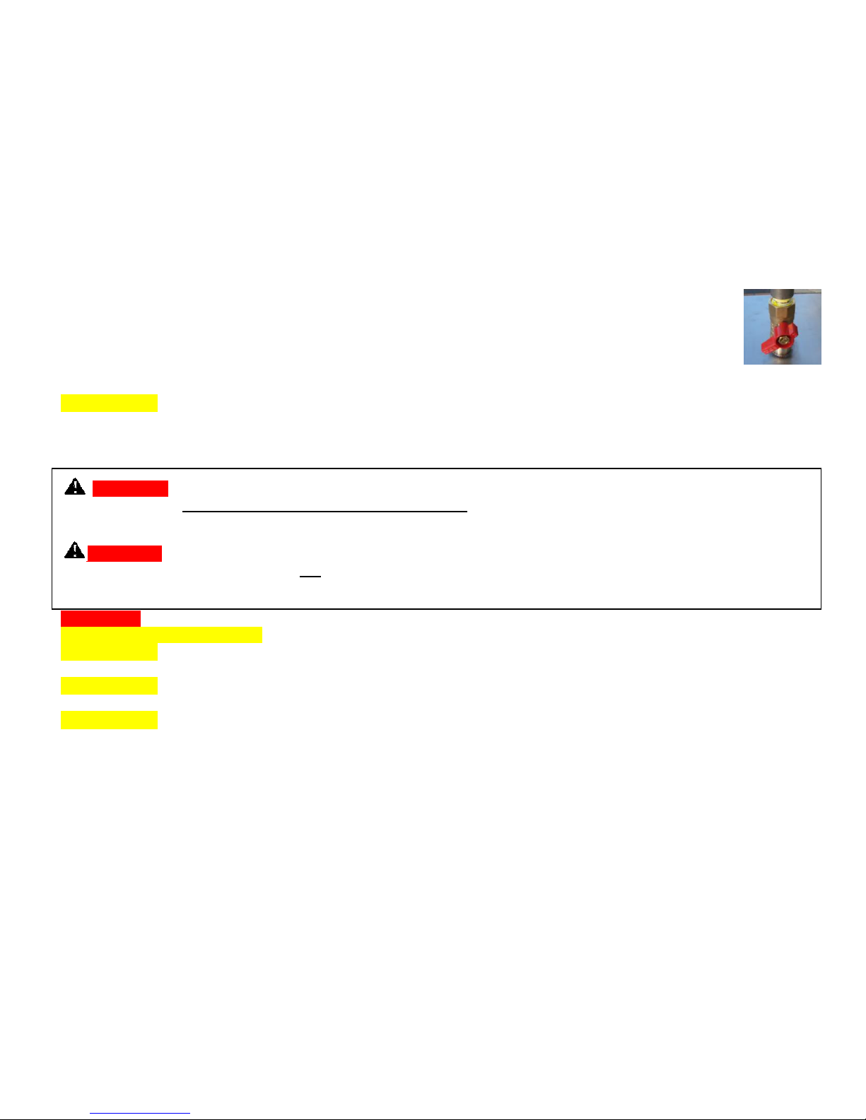
WARNING: All fire pits must have a gas shutoff on the outside of the exterior of the fire pit to allow for emergency shut off and
maintenance. The gas shutoff should not be used to adjust flame height.
WARNING: Select a location where the fire pit can be attended during operation. Never leave an operating fire pit unattended or
by someone not familiar with its operation or emergency shut off locations.
WARNING: Both children and adults should be alerted to the hazards of high surface temperatures and should stay away to avoid
burns and clothing ignition.
WARNING: Young children should be carefully supervised when they are in the area of fire pit.
WARNING: Clothing or other flammable materials should not be placed on or near fire pit.
WARNING: Fire pits create very high temperatures - Combustibles must be located far enough away that there is no risk of
ignition.
IMPORTANT: It is recommended that material such as granite, marble or other dense stone be kept away from heat and
especially flame due to risk of cracking. Manufacturer is not responsible for damage.
Select a location above ground with good drainage and allows easy access for installation and maintenance of the fire
pit.
Pick a location that allows sufficient horizontal room to enjoy the fire pit while allowing a safe distance from the heat
and flame.
3) Construction of the Enclosure
WARNING: For electronic ignition models there must be an electrical shut off (wall switch and breaker) on the exterior of the fire
pit or on adjacent wall to allow for emergency shutdown and maintenance. Verify correct 110VAC, 1 amp or 24VAC 4 amp supply.
All electronic applications should utilize a GFCI protected circuit.
WARNING: For 24V systems a Class II, 24VAC, 4 amps (14 gauge wires) must be supplied to the fire pit and able to be
switched on and off from a remote location to allow for easy access or emergency.
WARNING: All fire pits must have a gas shutoff on the outside of the exterior of the fire pit to allow for emergency shut off and
maintenance. The gas shutoff should not be used to adjust flame height. Refer to your local codes.
WARNING: Use noncombustible materials and construction for gas supply, power and enclosure. A metal outlet box should be
used inside the enclosure for electronic ignition models.
WARNING: We prefer the enclosure incorporate 4 vents total (minimum 18 sq. inches each side) to reduce the risk of thermal
shutdown on the EI Series- some enclosures may require more ventilation based on material, size and extended use. The minimum
requirement is the enclosure incorporate 1 vent on at least 2 sides (2 vents total) at a minimum size of 18 sq. inches of total free area
each (Example: 3”x 6” or larger) to ensure that heat and residual gas can escape. Installation of the vents in the mid to lower area of
the enclosure is recommended. Failure to properly vent enclosure may result in the fire pit overheating or explosion. Continuous
overheating could lead to heat damage to internal components. The vent may work as a drain as well when installed at bottom
sidewall to prevent water build up.
WARNING: The interior void space of the enclosure surrounding the valve box cannot be filled with any material (gravel, crushed
rock, concrete, etc.) - It is a requirement to have a minimum of 2” under the valve box for proper ventilation and drainage.
WARNING: The fire pit assembly should be recessed a minimum of 2.25” from the top of the enclosure to protect flame from
being blown out. Some areas may require more in the range of 4 to 6”.
WARRANTY REQUIREMENT: Do not daisy chain wiring for multiple fire pit installations. Each fire pit must have dedicated
wiring.
8/17/2016 850-EI
3
WARRANTY REQUIREMENT: The enclosure must be constructed on a stable surface. The weight of the fire pit must be
Installation
We suggest that our products be installed by professionals
that are locally licensed by the authority having
jurisdiction in gas piping.
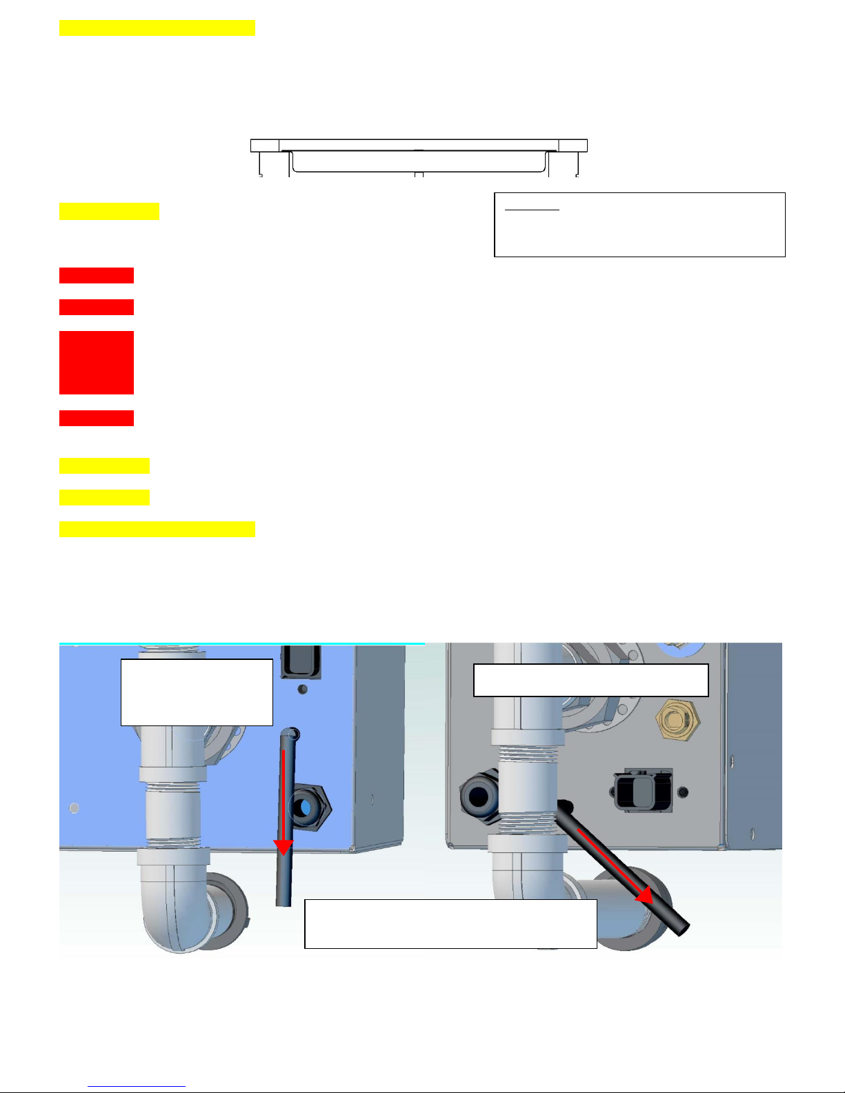
Side Mount –
Round, Square,
Rectangular Units
Vertical Mount - Linear Unit
Antenna extension cable is available for
installations that have poor reception.
supported by the pan and not by any control/valve box. For electronic ignition models the control/valve box must be above grade
with adequate drainage to prevent water damage to the controls inside the box.
Make sure that the structure is level. We recommend the use of the installation collar (optional) that may be mortared
into the surround.
HPC recommends that the pan lip is recessed on trough (linear), and large round products as illustrated below. HPC
cannot guarantee the lip on all of our products will be perfectly flat and will not warp due to heat.
IMPORTANT: Product must be accessible for service.
4) Installation of a Fire Pit
WARNING: We suggest that our products be installed by professionals that are locally licensed by the authority having jurisdiction
in gas piping.
WARNING: Confirm this appliance is built for gas used – natural gas or LP. Do not use natural gas appliance with LP or LP
appliance with natural gas. Refer to the label on the appliance.
WARNING: To prevent damage, unhook fire pit from gas supply for pressure leak tests.
WARNING: Burn testing - It is the responsibility of the qualified installer to test for gas leaks at all connections.
WARNING: When filling the pan with lava rock and/or decorative glass, the instructions in Section 5 must be followed.
WARNING: Gas Plumbing Connections: Use only joint compound or tape that is resistant to all gases. Apply joint compound to all
male pipe fittings only- DO NOT use on FLARED fittings. Be sure to tighten every joint securely.
WARNING: For systems with an extended or detached valve box: the area in which the valve box is installed must conform to all
installation requirements to include but not limited to location, construction, venting and local codes. Failure to do so may result in
personal injury property damage or explosion.
IMPORTANT: Fuel line sizing is the responsibility of the installer and must be able to supply 1.5 times the stated maximum BTU
for the product.
IMPORTANT: Ensure any flex line that may be used from the permanent main fuel supply to the product is rated to the stated max
BTU of the product and certified to ANSI Z21.75*CSA 6.27.
WARRANTY REQUIREMENT: Electronic Ignition fire pits come with a sheet of insulation between pan and valve box to protect
internal components from heat damage. This may need to be trimmed on smaller enclosures for proper fit. Please use insulation at all
times.
Antenna position for “Hi/Lo” models – For best results the antenna should be pointed down as much as possible depending on the
configuration and the onsite conditions. Be careful not to damage the antenna during installation or service.
8/17/2016 850-EI
4
1. Refer to cut sheets on our website for important dimensional information for your fire pit.
2. Plan your project well in advance to comply with all instruction and codes and allow for access and serviceability of the
product.
3. Purge gas lines of air.
4. Perform all leak tests with leak detector or leak reactant.
5. Verify correct gas type and pressure.
6. Perform leak test on main gas supply. Repair leaks as necessary.
7. Shut off gas supply and power to fire pit.
8. Connect fire pit to main gas supply. If using flex line avoid sharp bends with flex line to prevent whistling.
9. Turn on gas supply and perform leak test on all inlet connections. Repair as needed.
10. For electronic ignition models hook up proper 110VAC or 24VAC electrical power following all local codes.
11. Position fire pit safely with access to all gas connections for testing.
12. Light fire pit. It may take several cycles to purge air from the lines.
13. Once fire pit is lit perform leak test on all gas connections. Repair as needed.
14. Turn off fire pit and allow cooling.
15. Apply media as described in Section 5.
16. Turn on fire pit again and perform leak test with media correctly installed. If gas leak is detected verify
correct media application and repair as needed.
17. If trimmer valve is installed adjust flame to desired height. (Never alter the product configuration).
18. Set fire pit in properly constructed enclosure (Section 3).
19. Verify correct operation and lighting.
20. Review safety manual with end user and instruct not to change/ modify fire pit or media.
21. Leave manual with end user.
IMPORTANT: On electronic ignition models please apply the Start Up and Shutdown decal next to control switch in an obvious
position.
5) Media
WARNING: FOR GLASS MEDIA USAGE WITH LP GAS - WHEN USING APPROVED DECORATIVE GLASS TO
COVER BURNER, APPLY ONLY ENOUGH TO HIDE BURNER. APPLYING OVER 1/2” MAY CREATE BACK
PRESSURE AND GAS LEAKAGE FROM AIR MIXER RESULTING IN LP POOLING UNDER FIRE PIT.
WARNING: FOR GLASS MEDIA USAGE WITH LP GAS - THE UNIT MUST BE TESTED WITH MEDIA OVER
BURNER FOR CONFIRMATION OF NO BACK PRESSURE CREATING GAS TO LEAK OUT OF AIR MIXER
VENTURI HOLES. THIS MAY HAVE TO BE DONE PRIOR TO PLACING IN ENCLOSURE IF NO ACCESS DOOR.
WARNING: The fire pit is designed to use approved media correctly installed over the burner to achieve proper combustion.
WARRANTY REQUIREMENT: Never install a mesh or screen under the media.
IMPORTANT: Media affects flame pattern greatly. It is possible to create an unusual flame pattern that could damage your
enclosure. Enclosure damage from an open flame fire feature is not covered under any warranty.
IMPORTANT: Lava rock/glass coverage should be at a minimum to prevent smothering of the flame and for correct operation –
See “Lave Rock & Glass Application” instructions before applying.
IMPORTANT: The use of concrete logs is not recommended.
8/17/2016 850-EI
5
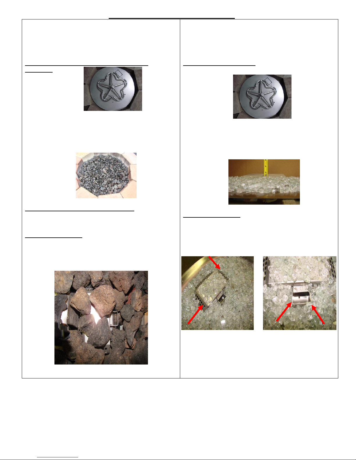
Lava Rock & Glass Application
Please follow the instructions below to add the
finishing touch to your fire pit. Particular attention needs to
be on the pilot assembly area. Incorrect media installation
will cause the pilot flame to suffocate and turn off pit or
delay main burner ignition.
Lava Rock Application- Standard size, 1”~3” pcs.
(part #657)
1) Install your fire pit per
instructions.
2) Apply standard lava rock only deep enough to cover ring
and pan- less than 2” above fire ring.
Lava Rock Application- Large size, 4”+ pcs.
3) Apply base coat of standard size lava rock as in Step 2, then
place large size lava rock loosely on top.
For Electronic Ignition
4) Blowout Box: Do not cover blowout box vents or opening
with lava rock or glass. Incorrect media installation will
cause the pilot flame to suffocate and turn off pit or delay
main burner ignition.
Decorative Glass Application
1) Install your fire pit per instructions.
2) Fill Pan with glass. Cover burner with 1/8 to ¼” of
glass. Do not over fill with glass. All LP installations
must be checked for back pressure with media installed.
Failure to do so may result in personal injury or
property damage.
For Electronic Ignition
3) Blowout Box: Do not cover blowout box vents or
opening with lava rock or glass. Incorrect media
installation will cause the pilot flame to suffocate and
turn off pit or delay main burner ignition.
DO NOT COVER VENTS! DO NOT COVER PILOT
OPENING!
6) Parts Lists
1) Electronic Ignition Flame Control System
2) Remote Control on “Hi/Lo” Models
3) Instructions
4) 120-HWI Bracket (Optional)
5) EI Manifold (Optional)
8/17/2016 850-EI
6
 Loading...