

®
CodeMax
Machine
Computerized
No. 1200MAXAA
Cutting
Code
No. 1200MAX
Exploded View
Parts List Inside
&
© 2013 HPC, Inc. • Schiller Park, IL • 60176 • USA • www.hpcworld.com
041013 36012_000_00
The CodeMax
Computerized Code Key Machine
®
This manual and the internal software and data of the CodeMax® described in this manual
are copyrighted by:
HPC, Inc., Schiller Park, Illinois, U. S. A.
The internal software and data is a work fully protected by the United States
Copyright Laws.
Federal Law: This manual or the internal software of the CodeMax®may not be copied,
translated, photocopied, microfilmed, or reproduced in any manner to be machine readable
in any form (in whole or in part), without the express written consent of the
copyright holder.
HPC, Inc.
Schiller Park, Illinois
Copyright 2008
CodeMax
®
1
X
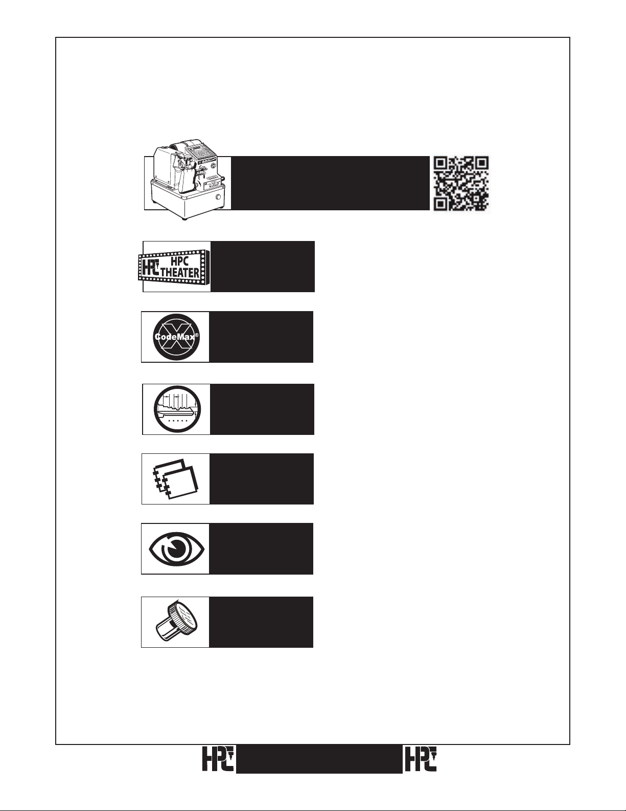
Visit the CodeMax® web page at
www.hpcworld.com/km/codemax
to learn about your machine.
Look For...
Look For...
Look For...
1 2 3 4 5
Look For...
Look For...
Watch Our
Other Videos
Features of the
CodeMax®
Depth & Space
Data
Manuals
and
Exploded Views
Exploded
Views
To watch the videos showing the
important features of the CodeMax®.
To learn the features of CodeMax®
Version 10 (Upgrades are available).
To view or download the current list
of DSD numbers and the key cutting
details for each one.
To view or download a PDF of the
CodeMax® Operation Manual.
To access the Exploded View and Parts
List to identify a spare part needed.
Look For...
Key Machine
Accessories
2
CodeMax
To see the accessories that are
available for your CodeMax®.
®

Index
1. Introduction . . . . . . . . . . . . . . . . . . . . . . . . . . . . . . . . . . . . . . . . . . . . . . . . . . . . . . . . . . . . . . 4
1.1 Product Packaging Checklist
1.2 Parts Designation
. . . . . . . . . . . . . . . . . . . . . . . . . . . . . . . . . . . . . . . . . . . . . . . . . . . . . . . . . . . 7
1.3 Preparation of the CodeMax
1.4 Basic Codemax Setup
1.5 Emergency Button
. . . . . . . . . . . . . . . . . . . . . . . . . . . . . . . . . . . . . . . . . . . . . . . . . . . . . . . .9
. . . . . . . . . . . . . . . . . . . . . . . . . . . . . . . . . . . . . . . . . . . . . . . . . . . . . . . . .10
. . . . . . . . . . . . . . . . . . . . . . . . . . . . . . . . . . . . . . . . . . . . . . . . . . 5
®
. . . . . . . . . . . . . . . . . . . . . . . . . . . . . . . . . . . . . . . . . . . . . . . . .8
2. Cutter Wheels
2.1 Cutter Wheel Descriptions
2.2 Changing Cutters
2.3 Resharpening Cutters
3. Holding And Gauging Keys
. . . . . . . . . . . . . . . . . . . . . . . . . . . . . . . . . . . . . . . . . . . . . . . . . . . . . . . . . . . .11
. . . . . . . . . . . . . . . . . . . . . . . . . . . . . . . . . . . . . . . . . . . . . . . . . . .11
. . . . . . . . . . . . . . . . . . . . . . . . . . . . . . . . . . . . . . . . . . . . . . . . . . . . . . . . . .12
. . . . . . . . . . . . . . . . . . . . . . . . . . . . . . . . . . . . . . . . . . . . . . . . . . . . . . .14
. . . . . . . . . . . . . . . . . . . . . . . . . . . . . . . . . . . . . . . . . . . . . . . . .15
3.1 Vise Jaws . . . . . . . . . . . . . . . . . . . . . . . . . . . . . . . . . . . . . . . . . . . . . . . . . . . . . . . . . . . . . . . . 15
3.2 Key Gauges
3.3 Gauging Methods
3.3.1 Standard Cylinder Key With Shoulder Gauge Using Jaw A
3.3.2 Standard Cylinder Key With Shoulder Gauge Using Jaw B
3.3.3 Red Full Short Tip Stop Gauging Using Jaw A
3.3.4 Red Middle Short Tip Stop Gauging Using Jaw A
3.3.5 Black Horseshoe Tip Stop Gauging Using Jaw B
3.3.6 Medeco
Using Jaw C (optional equipment)
3.3.7 Black Horseshoe Full End Tip Stop Gauging Using Jaw A or B
4. Key Cutting Methods
4.1. Stand Alone Key Cutting
4.1.1
4.1.2 Medeco® Keys
4.1.3 After The Key Has Been Cut
4.1.4 Additional Notes
4.2 Computer Assisted Key Cutting
4.3 Micrometer Key Cutting
. . . . . . . . . . . . . . . . . . . . . . . . . . . . . . . . . . . . . . . . . . . . . . . . . . . . . . . . . . . . . .19
. . . . . . . . . . . . . . . . . . . . . . . . . . . . . . . . . . . . . . . . . . . . . . . . . . . . . . . . . .19
. . . . . . . . . . . . . . . . . . 19
. . . . . . . . . . . . . . . . . . 21
. . . . . . . . . . . . . . . . . . . . . . . . . . . . 23
. . . . . . . . . . . . . . . . . . . . . . . . . 24
. . . . . . . . . . . . . . . . . . . . . . . . . . 25
®
– Standard Commercial Jaw . . . . . . . . . . . . . . . . . . . . . . . . . . . . . . . . . . 26
. . . . . . . . . . . . . . . . . . . . . . . . . . . . . . . . . . . . . . 26
. . . . . . . . . . . . . . 27
. . . . . . . . . . . . . . . . . . . . . . . . . . . . . . . . . . . . . . . . . . . . . . . . . . . . . . 29
. . . . . . . . . . . . . . . . . . . . . . . . . . . . . . . . . . . . . . . . . . . . . . . . . . . . 30
Standard Keys
. . . . . . . . . . . . . . . . . . . . . . . . . . . . . . . . . . . . . . . . . . . . . . . . . . . . . .
. . . . . . . . . . . . . . . . . . . . . . . . . . . . . . . . . . . . . . . . . . . . . . . . . . . . . . 32
. . . . . . . . . . . . . . . . . . . . . . . . . . . . . . . . . . . . . . . . . . 35
. . . . . . . . . . . . . . . . . . . . . . . . . . . . . . . . . . . . . . . . . . . . . . . . . . . . 36
. . . . . . . . . . . . . . . . . . . . . . . . . . . . . . . . . . . . . . . . . . . . . . 37
. . . . . . . . . . . . . . . . . . . . . . . . . . . . . . . . . . . . . . . . . . . . . . . . . . . . 39
30
5. Recalibration Of The CodeMax
5.1 Electronic Calibration
5.1.1 Depth Instructions
5.1.2 Space Instructions
. . . . . . . . . . . . . . . . . . . . . . . . . . . . . . . . . . . . . . . . . . . . . . . . . . . . . . 43
. . . . . . . . . . . . . . . . . . . . . . . . . . . . . . . . . . . . . . . . . . . . . . . . . . . 44
. . . . . . . . . . . . . . . . . . . . . . . . . . . . . . . . . . . . . . . . . . . . . . . . . . . 46
5.1.3 DSD Specific Instructions
5.2 Manual Calibration
Space Calibration
. . . . . . . . . . . . . . . . . . . . . . . . . . . . . . . . . . . . . . . . . . . . . . . . . . . . . . . . 50
. . . . . . . . . . . . . . . . . . . . . . . . . . . . . . . . . . . . . . . . . . . . . . . . . . . . . . . . . . 50
®
. . . . . . . . . . . . . . . . . . . . . . . . . . . . . . . . . . . . . . . . . . . 43
. . . . . . . . . . . . . . . . . . . . . . . . . . . . . . . . . . . . . . . . . . . . . 48
5.2.1 Cutting Too Close To The Tip On Keys Gauged From The Tip
5.2.2 Cutting Too Far From The Tip On Keys Gauged From The Tip
5.2.3 Cutting Too Far From The Shoulder
5.2.4 Cutting Too Close To The Shoulder
5.3 Depth Adjustment
6. Updates
. . . . . . . . . . . . . . . . . . . . . . . . . . . . . . . . . . . . . . . . . . . . . . . . . . . . . . . . . . . . . . . . . 60
7. Troubleshooting
8. Glossary
9. Exploded Views
. . . . . . . . . . . . . . . . . . . . . . . . . . . . . . . . . . . . . . . . . . . . . . . . . . . . . . . . . . . . . . . . 62
. . . . . . . . . . . . . . . . . . . . . . . . . . . . . . . . . . . . . . . . . . . . . . . . . . . . . . . . . 59
. . . . . . . . . . . . . . . . . . . . . . . . . . . . . . . . . . . . . . . . . . . . . . . . . . . . . . . . . . 61
. . . . . . . . . . . . . . . . . . . . . . . . . . . . . . . . . . . . . . . . . . . . . . . . . . . . . . . . . . 64
. . . . . . . . . . . . . . . . . . . . . . . . . . . . . . . . . . . . . 55
. . . . . . . . . . . . . . . . . . . . . . . . . . . . . . . . . . . . . 57
10. Preventive Maintenance, Lubrication, Repairs, and Guarantee
CodeMax
®
. . . . . . . . . . . . . . . 51
. . . . . . . . . . . . . . . 53
. . . . . . . . . . . . . . . . . .
68
3

1. Introduction
Thank you for purchasing this CodeMax® Machine; we appreciate your business.
The CodeMax® represents the latest development in the industry’s first computerized code
machine. Utilizing cutting edge technology, this version allows for electronic calibration,
DSD modification, and updates installed by your computer.
Please read this manual to become familiar with the features and operation of your
CodeMax®. This machine is updated every year with new information and features. Please
complete and return the enclosed warranty registration card to ensure you receive notice of
future updates.
We are confident your CodeMax® will provide years of service for you. If you have any
questions or comments about this machine (or any HPC products), please contact us.
Thank you,
HPC, Inc.
3999 N. 25th Avenue
Schiller Park, Illinois 60176
U.S.A.
Tel: 847.671.6280
Toll-free in U.S.A. and Canada: 800.323.3295
Fax: 847.671.6343
Email: hpc@hpcworld.com
www.hpcworld.com
4
CodeMax
®
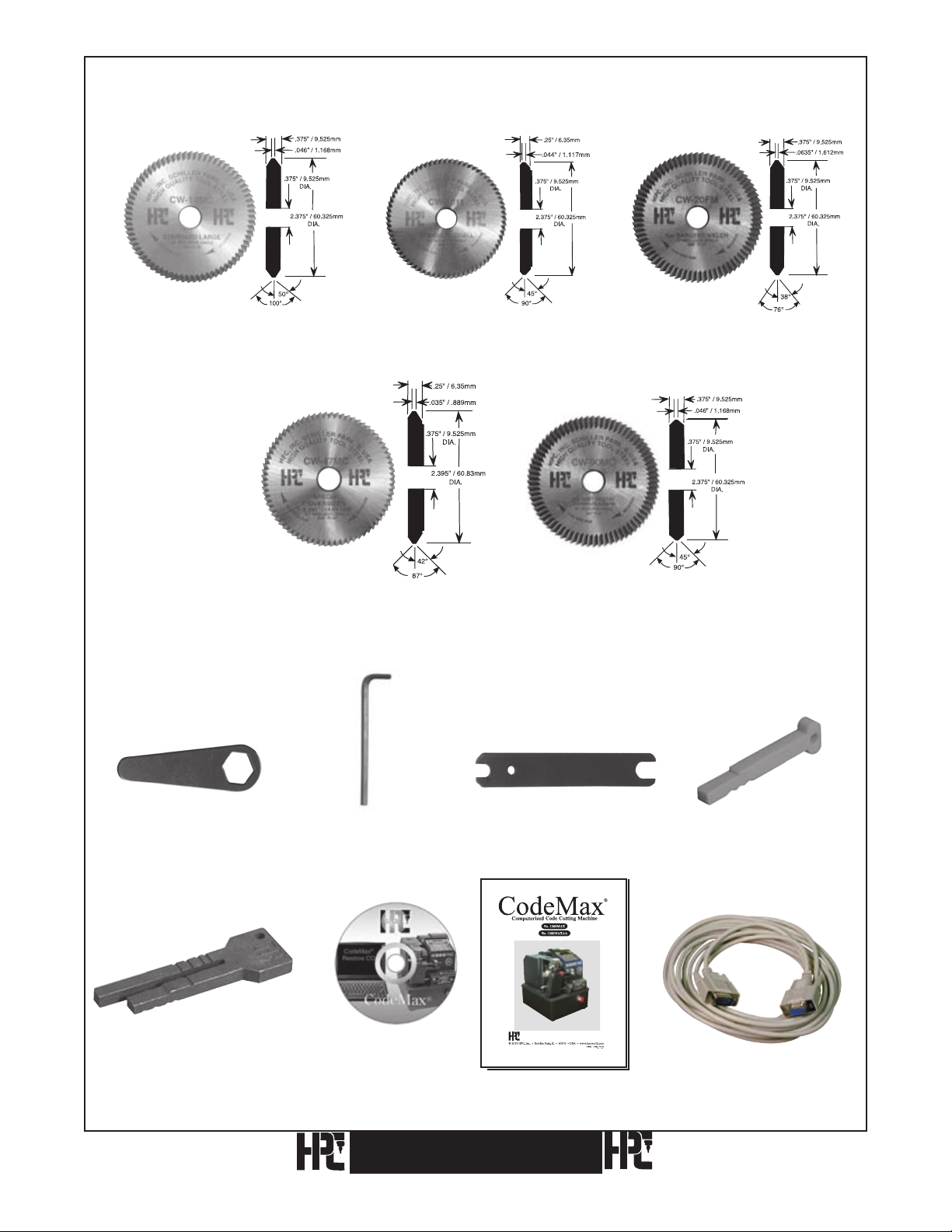
1.1 Product Packaging Checklist
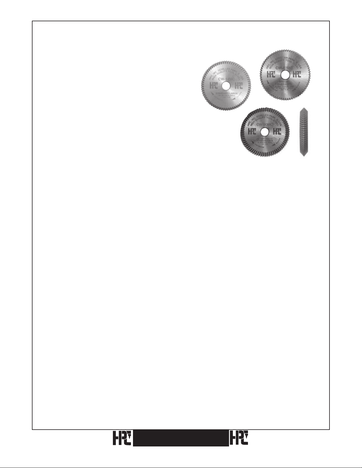
HPC Cutter Wheel (installed) HPC Cutter Wheel HPC Cutter Wheel
(CW-14MC) (CW-1011) (CW-20FM)
HPC Cutter Wheel HPC Cutter Wheel
(CW-47MC) (CW-90MC)
Cutter Wrench Allen Wrench, 5/64" Cutter/Adjustment Wrench Red Tip Gauge
(WRENCH-3) (WRENCH-2) (WRENCH-1) (CM-1054MA)
Horseshoe Tip Gauge DSD List
(CM-1054R) CodeMax® Update &
Restore CD
(MAX-CD)
CodeMax
CodeMax® Manual
(1200MAX-MAN)
®
Serial Cable
(CABLE-25S)
5

Your CodeMax® computerized code machine comes with the following additional items
(see the photos on the previous page):
Qty. Stock No. Description
1 CW-14MC HPC Cutter Wheel (Installed on Machine)
1 CW-1011 HPC Cutter Wheel
1 CW-20FM HPC Cutter Wheel
1 CW-47MC HPC Cutter Wheel
1 CW-90MC HPC Cutter Wheel
1 WRENCH-1 Cutter Shaft/Adjustment Wrench
1 WRENCH-3 Cutter Nut Wrench
1 WRENCH-2 Allen Wrench, 5/64-inch
1 CM-1054R Black Horseshoe Tip Gauge
1 CM-1054MA Red Tip Gauge
®
1 MAX-CD DSD List, CodeMax
®
1 1200MAX-MAN CodeMax
Manual
Update and Restore CD
1 — Warranty Registration Card
1 CABLE-25S Serial Cable
6
®
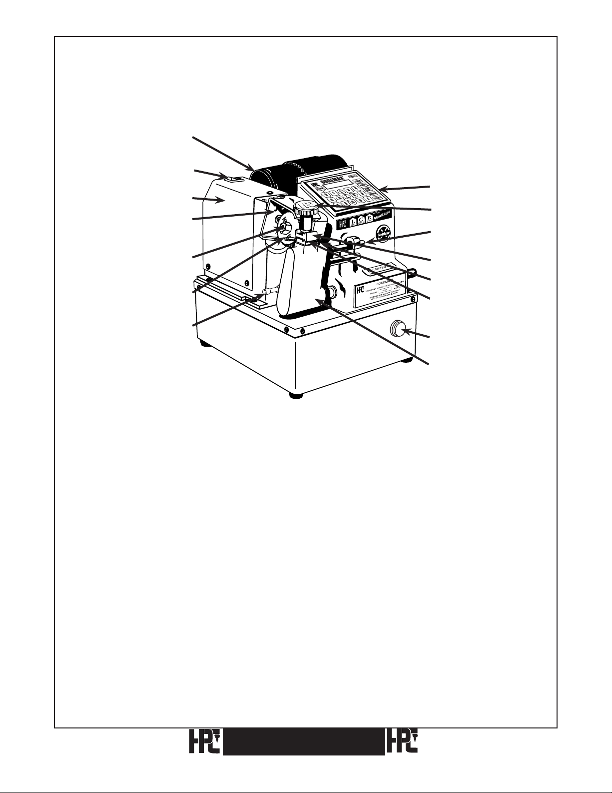
1.2 Parts Designation
X
120VAC Motor (CM-1080MA)
240VAC Motor (CM-1070)
Power Switch
120VAC (KM-1017)
240VAC (9160-SW)
Automatic Angler
Cutter Head (KM-1016)
Keypad (MAX-4)
Wing Nut (EGN-1)
Eccentric Shaft
(CM-1041)
Cutter Nut (CM-1039MA)
Cutter (Wide Selection
Available)
Shoulder Gauge (CMB-FG)
Top Jaw (CM-1056MA)
Tip Gauge (CM-1054MA)
Bottom Jaw
(CM-1055MA)
Emergency Stop Button
(MAX-50)
Pivot Arm (CM-1024X)
CodeMax® CodeMax
7

1.3 Preparing To Use The CodeMax® Computerized Key Machine
Before using the CodeMax® key machine, read this manual in order to gain a thorough
understanding of all of its capabilities. You will receive peak performance and efficiency
from your machine by fully comprehending all of its functions.
Make sure that the power outlet that the CodeMax® will attach to is properly wired, i.e.,
grounded with correct hot and neutral leads. If the outlet is not wired properly or power
from the available outlet is not regular (i.e., you experience frequent power brownouts), the
CodeMax® may malfunction. While the CodeMax® contains an internal surge protector, it
is recommended that you also use an external surge/brownout protector when operating the
CodeMax®.
8
CodeMax
®
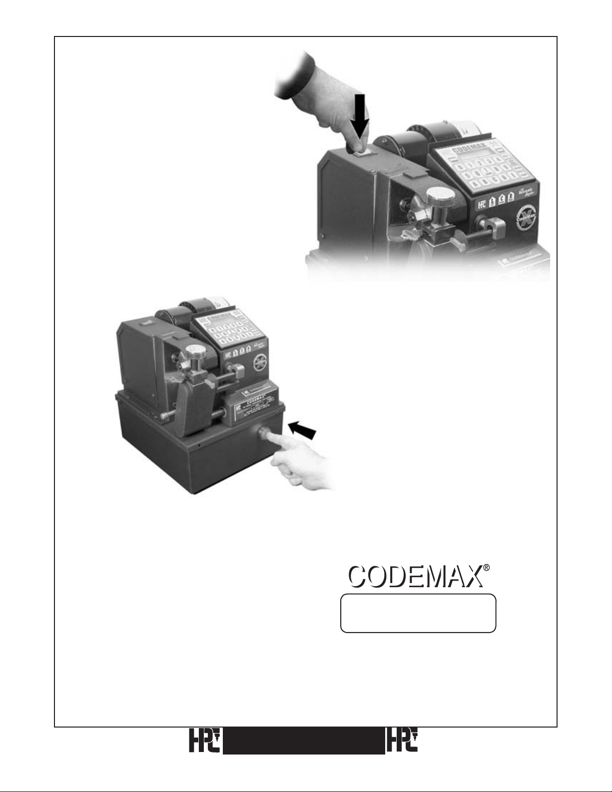
1.4 Basic CodeMax® Setup
Find a suitable location for the
CodeMax® machine. This should be
an area with good ventilation for the
cutter motor and easy access to the
front and top of the machine for use
and cleaning.
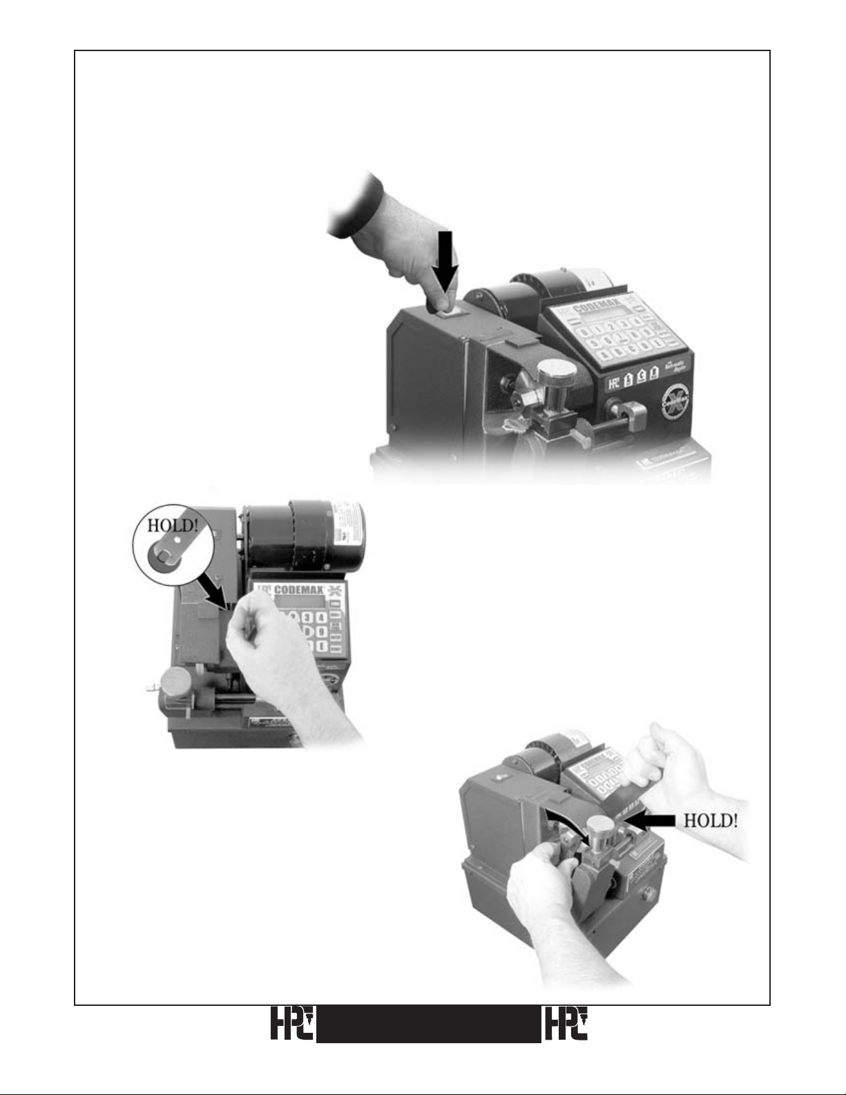
Plug the cord into the back of
the CodeMax® and then into the
appropriate electrical outlet. Turn
on the CodeMax® using the switch
located at the left rear of the
machine.
The display will read “Emergency
Stop Depressed”. Make sure there
is nothing interfering with the
pivot arm, cutter wheel, and motor.
Push the large, red emergency stop
button located at the front of the
CodeMax® until it pops out.
The CodeMax® will go through a brief test
routine to prepare itself for use. The CodeMax®
display will read “CodeMax Ready”, indicating
that the machine is in its main screen and ready
for use.
CodeMax
CodeMax Ready
HPCSoft Version 10.0
®
9
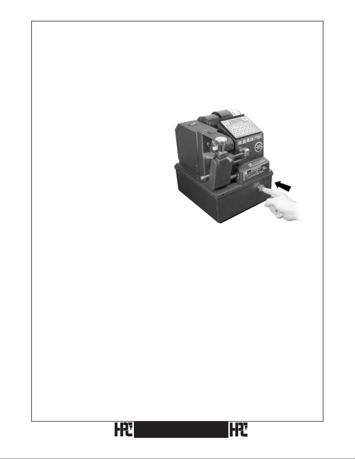
1.5 The Emergency Stop Button
The CodeMax® has an emergency stop button installed.
Pushing the emergency stop button at any time will immediately freeze the operation in
which the machine is engaged. For example, if you started the cutting process and realized
you had the wrong cutter or key blank, pushing the emergency stop button would instantly
turn off the cutter motor and stop the pivot arm from traveling.
To reset the CodeMax®, after the
machine freezes, push the emergency
stop button until it pops out, and
the machine will return to its Home
Position. Make the necessary
adjustments (e.g. put the shoulder
gauge down, or install the correct
cutter or key blank), and start the key
cutting process again.
*Note: When the emergency stop button is pushed, the CodeMax® will clear the bittings entered,
if the bittings were entered directly on the CodeMax
®
keypad.
If you have any questions, please call the HPC Service Dept. 1-800-323-3295.
10
CodeMax
®
2. Cutter Wheels
2.1 Cutter Wheel Descriptions
The model CodeMax®is supplied with five
standard cutter wheels. The CW-1011 cutter
is used for cabinet, padlock, and most vehicle
applications. The CW-14MC cutter is used for
cutting most standard cylinder keys. The CW90MC is similar to the CW-14MC but makes cuts with
a steeper slope for special applications. The CW-20FM cutter
is a 76 degree cutter used for Sargent applications.
The CW-47MC is an 87 degree cutter used for certain
automotive applications.
Flat steel cutters, the Medeco® cutter (CW-1012), the Emhart cutter (CW-1013), and the
Assa Cutter (CW-32MC) are all optional cutter wheels that are available for use with the
CodeMax®. Additionally, the Medeco® Commercial Jaw (MJ-1) is an optional jaw for
cutting the Medeco® Standard Commercial Keyway (Air). The KeyMark® Jaw is available
from Medeco®.
CodeMax
®
11
2.2 Replacing Cutter Wheels
The following procedure is recommended when changing cutters:
IMPORTANT NOTE: Be sure the cutter is installed for a clockwise rotation, with the arrow
facing the outside, so it can be seen.
1) Turn the CodeMax® off.
3) Loosen the cutter shaft nut with
the 3/4 inch WRENCH-3 by turning
it clockwise (left hand thread). The
cutter shaft is threaded with reverse,
left-hand thread.
2) Hold the cutter shaft with the
1/2 inch end of WRENCH-1.
12
CodeMax
®

4) Remove the cutter. Slide the
replacement cutter onto the shaft.
IMPORTANT NOTE: Be sure the cutter is installed
for a clockwise rotation, with the arrow facing the outside, so it can be seen.
6) Install the nut, turning
counterclockwise
onto the cutter shaft with the
3/4 inch wrench.
Do not overtighten the nut!
5) Hold the shaft with the 1/2 inch WRENCH-1.
CodeMax
®
13

2.3 Resharpening Cutter Wheels
One of the most important features of the CodeMax® is its capability to maintain correct
depth and spacing with virtually no setup time involved, including the changing of the
cutter wheels. This capability is dependent upon the use of cutters whose outside diameters
are carefully calibrated. We recommend using only HPC cutter wheels.
Eventually, cutters become worn and should be replaced. We do not recommend sharpening
cutters.The diameter of a resharpened
if no depth adjustment is made.
cutter is smaller and will therefore make cuts shallower
See Depth Adjustment Section (5.2) for further information.
In order to maintain matched cutter diameters, all cutters for the CodeMax® must be
resharpened at the same time to account for material lost during this process.
14
CodeMax
®
3. Holding And Gauging Keys
The CodeMax® comes from the factory calibrated and ready to cut keys to manufacturers’
specifications. The necessity for special gauges and adapters has been held to a minimum.
Basically, one upper Vise Jaw, which is removable and reversible, covers the greatest range
of key cutting. This upper Vise Jaw (CM-1056MA) is marked “A” on one side and “B” on
the other. When the A side is in use, the letter “A” faces up, in sight of the operator. The
B side is in position when the “B” is seen. Manufacturers’ data and information about the
corresponding jaws can be found on the DSD-CD.
3.1 Vise Jaws
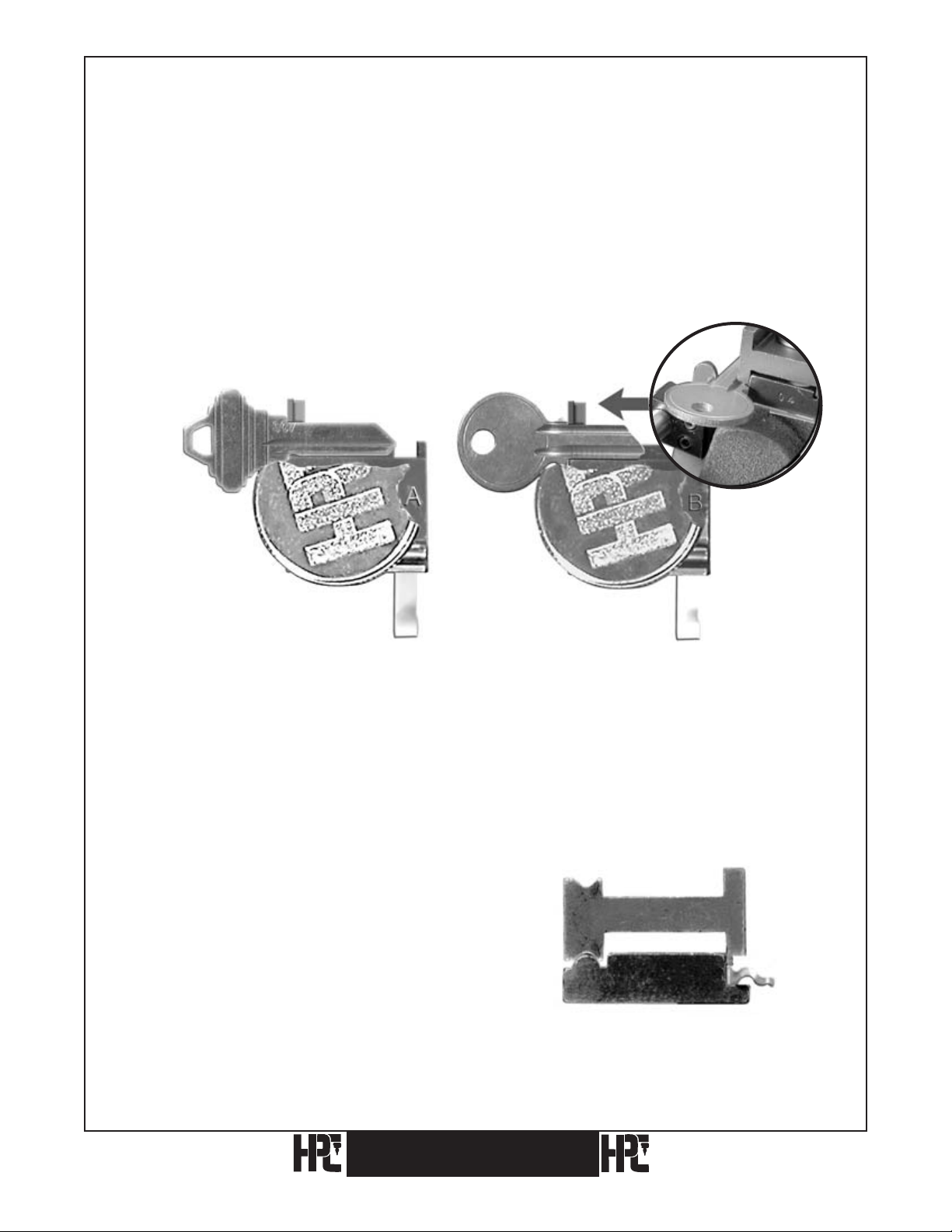
Jaws A & B – Standard Jaws (CM-1056MA) Installed
Fig. 1A. Properly seated key in jaw A. Fig. 1B. Properly seated key in jaw B.
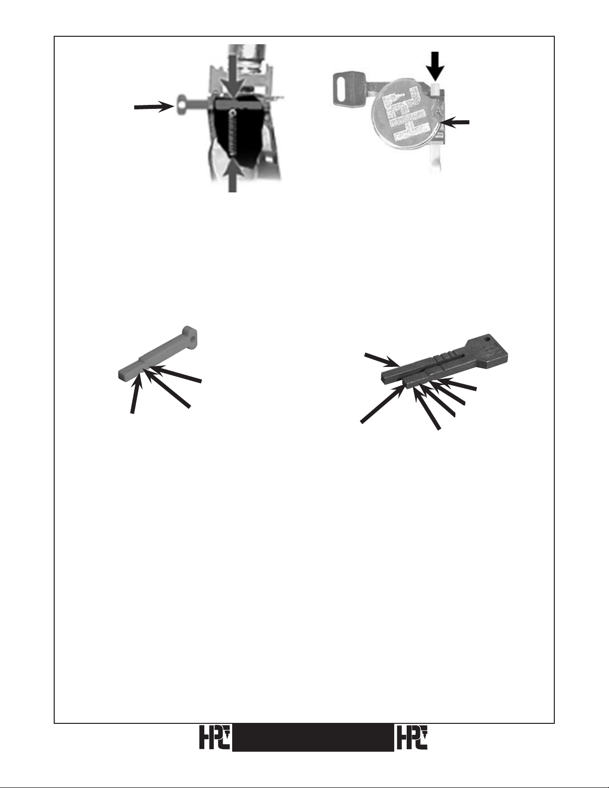
Vise jaw A is used for all standard keys with the deepest cut no less than .142 inches (see
Fig. 1A). Jaw B is used for small keys that use cuts of such great depth that a lip on the jaw
is provided to hold the key closer to the cutter. See Fig. 1B.
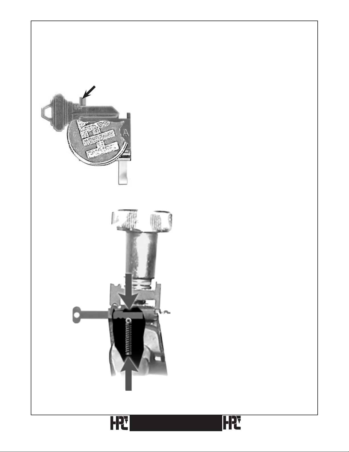
Some keys (Best™ for example) will tip
when using Jaw A. If there is a problem
holding the key in Jaw A, use Jaw B
by placing the lip of Jaw B on the edge
of the blank. The blank must still be
positioned at the back of the bottom jaw.
See Fig. 2.
Fig. 2.
CodeMax®
15
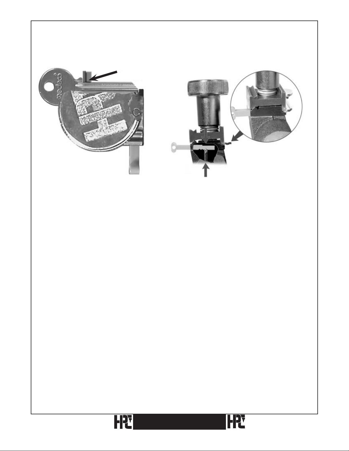
Jaw C – Medeco® Jaw (MJ-1) Optional Equipment Required For Cutting Medeco®
Keys (Not Required For Biaxial Keys)
Shoulder Gauge
Fig. 3A. Fig. 3B. Properly seated key in jaw C.
An optional cutter (CW-1012) and Jaw C (MJ-1) are required to cut commercial level
Medeco® keys. Both parts are readily available from your HPC distributor. Biaxial keys
only require the CW-1012 cutter, not MJ-1.
The optional Jaw C is a specially milled CodeMax® jaw. It is required for holding the
standard Medeco® keys (see Fig. 3A). Vise Jaw C is milled to fit and firmly nest into
the Medeco® commercial key grooves. The proper and firm grip provided by Jaw C is
necessary due to the extremely deep cuts used on Medeco® keys. Instructions for using
Medeco’s KeyMark® Jaw are available from Medeco®.
Gauge the key from the shoulder, making sure the key grooving and special jaw milling are
nested together (see Fig. 3B).
16
CodeMax
®
3.2 Key Gauges
Shoulder
Gauge
Fig. 4 Fig. 5 Fig. 6 Fig. 7
Red Tip
Gauge
Horseshoe Tip
Gauge
Position 1
Top View of
Horseshoe
Tip Gauge in
Position 1
Red Tip
Gauge
Top View of
Red Tip Gauge
in Position 2
Position 2
Fig. 8 Fig. 9 Fig. 10
Horseshoe Tip
Gauge
Position 2
Keys with shoulders are gauged by placing them squarely into the vise assembly and
swinging the key Shoulder Gauge (CMB-FG) upward. The key is moved laterally, as
required, until the key’s shoulder just touches the left hand surface of the gauge (see Fig. 4).
Note: Be sure to tighten the wing nut and swing the Shoulder Gauge back down before starting
the cutting process.
Keys without shoulders are properly gauged by using the Red Tip Gauge (CM-1054MA) or
the black Horseshoe Tip Gauge (CM-1054R). The bottoms of these tip gauges have several
grooves, allowing them to be held in different positions by a spring loaded ball bearing.
These tip gauges are pulled back to the first position where they are held within the base of
the lower jaw (Figs. 5 & 6) safely out of the path of the cutting wheel.
See Figs. 7, 8, 9, & 10 for tip gauge references.
CodeMax
®
17
Red Tip Gauge
Red Tip
Gauge
Wing Nut
Fig. 11. Fig. 12. 5 Pin Ford.
Position 3
In the third position, the Red Tip Gauge is sent forward into the third groove and this is
the proper setting for old, 5-pin Ford keys (see Figs. 11 & 12). To clamp and gauge double
sided Ford type keys, the offset of the key is set against the face of the jaw. Slide the key to
the right until the tip butts against the tip gauge and tighten the wing nut. The blank is held
off the key rest by this method, thereby eliminating the need for any special blocks (see
Figs. 11 & 12).
Right Leg
Position 3
Position 1
Position 2
Left Leg
Position 1
Position 4
Position 3
Position 2
Red (Plastic) Tip Gauge (CM-1054MA) (Black) Horseshoe Tip Gauge (CM-1054R)
Position 1: Out of the way Position 1: Best – Right Leg
Position 2: Best Position 2: Ford – Right Leg
Position 3: Ford Position 3: Best – Left Leg (same as 2 red)
Position 4: Ford – Left Leg (same as 3 red)
Note: Red Tip Gauge should be pulled back to position 1 or removed when
cutting shoulder gauged keys.
Remove Black Horseshoe Tip Gauge completely when gauging or cutting shoulder gauged
keys or when gauging from positions 3 and 4 prior to cutting.
Positions 1 and 2 of Horseshoe Tip Gauge are designed to bring the tips of key blanks even
with the right side of the jaw. If the right leg is bent inward (so the tip gauge doesn’t enter
the jaw) or bent outward (so key blanks gauge beyond the right side of the jaw) the right leg
should be gently tapped back into alignment.
18
CodeMax
®
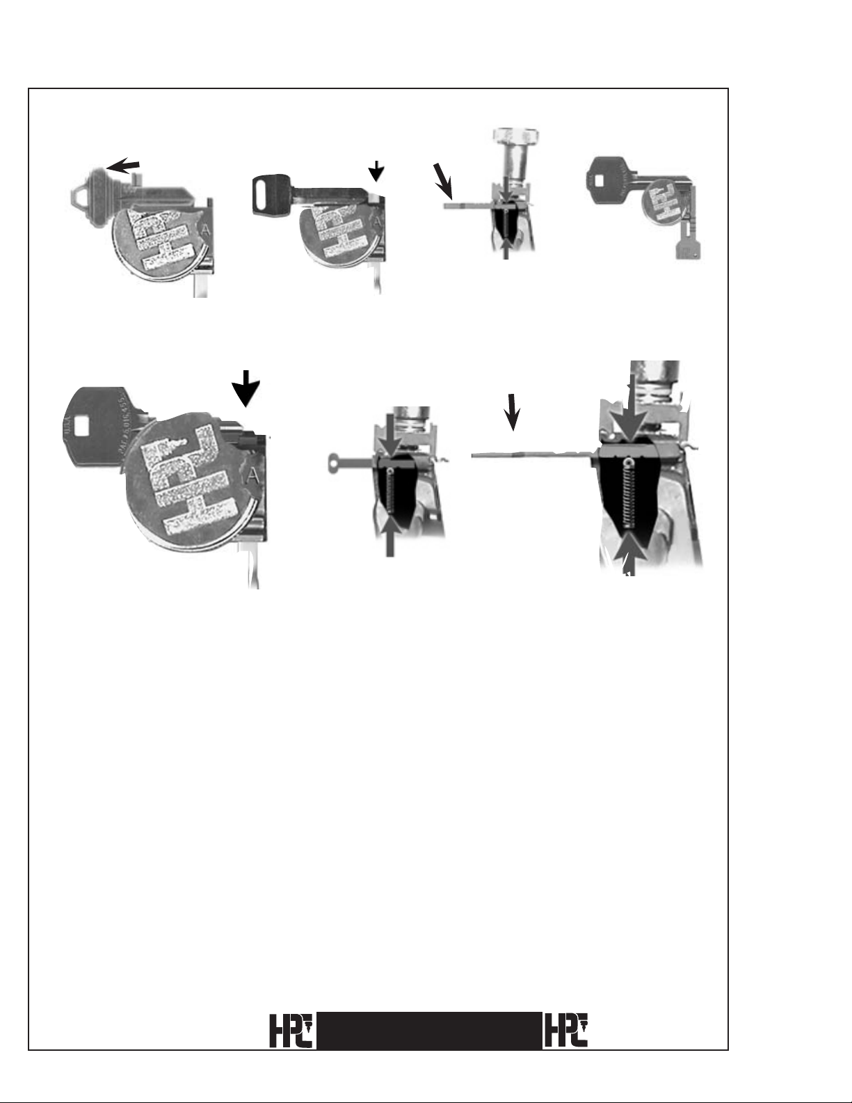
3.3 Gauging Methods
3.3.1 Standard Cylinder Key With Shoulder Gauging Using Jaw A (Example:
Schlage, DSD #60)
Shoulder Gauge
1) Place the key blank in Jaw A. Raise the Shoulder
Gauge to its upright position. Position the key blank
with the shoulder of the key lightly touching the left
hand edge of Shoulder Gauge (avoid undue pressure
– see Note below).
Note: The spacing of the key cuts can be significantly affected
by any damage incurred to the Shoulder Gauge. Handle the
Shoulder Gauge with care! Damage to the Shoulder Gauge
most often occurs when the gauge comes in contact with the
cutter, or when undue pressure is used when gauging against
the key’s shoulder. Make sure to gently position the key blank
against the Shoulder Gauge to avoid damage.
Red Tip
Gauge
Position 1
CodeMax
2) Make sure the Tip Gauge
(if installed) is out of
the way. The Red Tip
Gauge is pulled to the rear
and safely in the detent
position (Position 1)
before continuing, and the
Horseshoe Tip Gauge is
removed.
®
19
3) Tighten the Wing Nut and flip the
Shoulder Gauge down before continuing.
Fig. 4. Wing Nut and Top Jaw of vise removed to show top view of the Bottom Jaw only, for key
positioning.
4) Make sure the key is lying flat
against the back of the Bottom Jaw
before tightening the Wing Nut.
20
CodeMax
®

3.3.2 Standard Cylinder Key With Shoulder Gauging Using Jaw B (Example: Master,
DSD #49)
Shoulder Gauge
Jaw B
Wing Nut
1) Place the key blank in Jaw B. Make sure that the key lies in front of the lip, and flat
against the lip. Raise the Shoulder Gauge to its upright position. Position the key
blank with the shoulder of the key lightly touching the left hand edge of Shoulder
Gauge (avoid undue pressure – see Note below).
Note: The spacing of the key cuts can be significantly affected by any damage incurred to the
Shoulder Gauge. Handle the Shoulder Gauge with care! Damage to the Shoulder Gauge most
often occurs when the gauge comes in contact with the cutter, or when undue pressure is used
when gauging against the key’s shoulder. Make sure to gently position the key blank against the
Shoulder Gauge to avoid damage.
Red Tip
Gauge
Position 1
3) Make sure that the key lies in front
of the lip, and flat against the lip.
2) Make sure the Tip Gauge is completely out
of the way, and that the Horseshoe Tip Gauge
is removed.
CodeMax
®
21

4) Tighten the
Wing Nut
and flip the
Shoulder Gauge
down before
continuing.
Wing Nut
Shoulder Gauge
in the Down Position
22
CodeMax
®

3.3.3 Red Tip Gauge In Position 3 (Full Short Tip Stop) Using Jaw A
(Example: Ford, DSD #34)
1) The Red Tip Gauge is pushed inward to
position 3.
Note: Make certain to pull the Tip Gauge to the rear
(position 1) before cutting.
Red Tip Gauge
Position 3
2) The key is gauged from the tip. Make sure
the Shoulder Gauge is lowered before continuing.
Fig. 3. The Wing Nut and Top Jaw of the vise removed
to show a top view of the Bottom Jaw only, for key
positioning and Tip Stop settings.
3) Make sure the blank is lying flat on the ledge
against the back of the Bottom Jaw before
tightening the Wing Nut.
CodeMax
Note: For Ford blanks (DSD#34), the key blank grooving
edge lies directly on the face of the jaw for ignition and
trunk keyways. No riser blocks are used.
®
23

3.3.4 Red Tip Gauge In Position 2 (Middle Short Tip Stop) Using Jaw A (Example:
KABA-PEAKS 6-Pin, DSD #608)
1) The Red Tip Gauge is pushed inward to Position 2.
The Tip Gauge is pulled to the rear (position 1)
while cutting.
Position 2
Note: Make certain to pull the Tip Gauge to the
rear (position 1) before cutting.
Red Tip Gauge
3) Be sure the key lies flat against the back
edge of the Bottom Jaw before
tightening the Wing Nut.
2) The key is gauged from the
bottom stop, not the tip.
Wing Nut
Jaw A
Red Tip Stop
24
Fig. 3. The Wing Nut and Top Jaw of the vise partially
removed to show a top view of the Bottom Jaw only
for key positioning and Tip Stop settings.
CodeMax
®

3.3.5 Black Horseshoe Tip Gauge In Position 1 (Short Tip Stop) Using Jaw B
(Example: DSD #3)
1) The Tip Gauge is pushed
inward to position 1.
2) The key is gauged from the bottom
stop of the key, not the tip.
Horseshoe Tip Gauge
Position 1
Wing Nut
Jaw B
Horseshoe Tip Stop
3) Slide the key to the right until the bottom
stop of the key touches the right leg of the
Horseshoe Tip Stop. Be sure the key lies
flat against the back edge of the bottom
jaw before tightening the wing nut.
Note: Undue pressure against the right leg will cause
the legs to spread, resulting in inaccurately cut keys.
4) Note the special holding on the key milling
using Jaw B. (The key must be lying flat against the
back ledge of the Bottom Jaw as shown.)
CodeMax
®
25

3.3.6 Medeco® Standard Commercial Key Using Jaw C (Optional
Equipment) With Shoulder Gauging (Example: DSD #51)
Shoulder gauge
1) The key shoulder touches the left
hand edge of the Shoulder Gauge.
Jaw C
Avoid undue pressure – see note
below.
Note: The spacing of the key cuts can be significantly affected by any damage incurred to the
Shoulder Gauge. Handle the Shoulder Gauge with care. Damage to the Shoulder Gauge most
often occurs when the gauge comes in contact with the cutter, or when undue pressure is used
in gauging against the key’s shoulder. Make sure to gently position the key blank against the
Shoulder Gauge to avoid damage.
Red Tip Gauge
2) The jaw and key grooves “nest” into each other.
The Tip Gauge (if installed) is pulled back to
the rear to position 1 (Horseshoe Tip Gauge is
removed). Open Jaw C only enough to slide the
key into position. Be sure the key groove and jaw
milling mate before tightening the Wing Nut.
Position 1
3) Flip the Shoulder Gauge down and tighten
the Wing Nut before proceeding.
Medeco® is a registered trademark of Medeco Security Locks, Inc.
26
CodeMax
®

3.3.7 Black Horseshoe Tip Gauge In Position 2 Using Jaw A or B
(Example: GM Modular 94+, DSD #259)
1) The Horseshoe Tip Gauge is
pushed inward to position 2.
Horseshoe Tip
Gauge
Position 2
2) The key is gauged from the tip as shown. Be sure
the key lies flat against the back of the Bottom
Jaw before tightening the Wing Nut. Lower the
Shoulder Gauge.
Note: Undue pressure against the right leg will cause the legs to
spread, resulting in inaccurately cut keys.
Note: On Ford blanks (DSD’s 35 and 261) the key blank grooving
edge lies directly on the face of the key vise. No riser blocks are
used.
CodeMax
®
27

Look For...
Look For...
Look For...
1 2 3 4 5
X
Visit the CodeMax® web page at
www.hpcworld.com/km/codemax
to learn about your machine.
See it in use!
Features of the
CodeMax®
Depth & Space
Data
To watch the videos showing the
important features of the CodeMax®.
To learn the features of CodeMax®
Version 10 (Upgrades are available).
To view or download the current list
of DSD numbers and the key cutting
details for each one.
Look For...
Look For...
Look For...
Manuals
and
Instructions
Exploded
Views
Key Machine
Accessories
To view or download a PDF of the
CodeMax® Operation Manual.
To access the Exploded View and Parts
List to identify a spare part needed.
To see the accessories that are
available for your CodeMax®.
28
CodeMax
®

4. Key Cutting Methods
1) Stand Alone Key Cutting utilizing the internal capabilities of the CodeMax®.
2) Computer
to the CodeMax® via a serial cable (No. CABLE-25S) attached to the back of the
CodeMax®.
3) Micrometer
CodeMax®.
Assisted Key Cutting using a computer loaded with HPC software connected
Key Cutting using space and depth information manually inputted into the
CodeMax
®
29

4.1 Stand Alone Key Cutting
4.1.1 Standard Keys
The computer chip in the CodeMax® contains a database of nearly 1000 DSD Numbers. DSD
stands for Depth and Space Data, these are charts of key-cutting information.
For Direct Digit keys (such as Schlage or Kwikset) or if you know the bitting needed for an
indirect-coded key (such as an automotive or furniture key), you can utilize the internal DSD
to cut a new key. Refer to the DSD List or to CodeSource® for the applicable DSD number,
gauge point and cutter to use.
For example, if you were cutting a key for a standard
Schlage large pin cylinder you would: Press DSD#.
Enter “60” (press “6”, then press “0”, then press ENTER
to accept this selection)
Note: At anytime during this process you can clear a wrong
entry or return to the previous screen by pressing CLEAR.
The CodeMax® displays the name of the selected
manufacturer and displays the correct gauging point.
For example, the Schlage
display will read “Use
Shoulder Stop as Gauge”.
*Note: Certain manufacturers,
such as Best, list bittings tip to
bow. Tip to bow bittings need to be
reversed to bow to tip order when
inputting.
Insert and gauge the key accordingly (refer to Section 3, Key Gauging for details).
The display then indicates “Enter Bitting”.
Enter the bitting desired starting with the cut
closest to the bow.* For this example we will
make thebitting “43264”. Enter “43264”
by pressing “4”, “3”, “2”, “6”, “4”, and
then ENTER.
The display now shows the
CodeMax® is READY to
CODEMAX
READY 43264
®
cut the key.
From the Ready screen, you have several options:
1. Press START to begin cutting the key bitting shown on the screen.
2. Press NEW CODE or CLEAR and enter in a new bitting. (Remember to
press Enter to accept the new bitting.)
3. Press CLEAR twice to return to the “Enter DSD Number” prompt, or twice
more to reset the CodeMax®.
30
CodeMax
®

4. P ress “A” to change to the Contour Cutting Mode. Contour Cutting will
remove peaks between cuts on a key, for smoother operating automotive keys (only
recommended for automotive keys). Press “A” again to return to the Standard
Cutting Mode.
CONTOUR
Switch Contour cutting on and off.
5. P ress “6” to decrease the rate of speed at which the pivot arm approaches
the cutter or press “8” to increase the rate of speed at which the pivot arm
approaches the cutter. This is particularly useful when dealing with hardened
keys and wanting to cut them at a slower rate.
CUT SPEED
Fewer bars = slower
More bars = faster
6. In the case of “Double-Sided Different” keys, after cutting the first side, press ENTER
to autoload the next DSD Number associated with the manufacturer chosen.
If cutting a single-sided key or if the second side is the same as the first, pressing
ENTER will return to the Main Screen.
CodeMax
®
31

4.1.2 Medeco® Keys
Some high security keys, such as Medeco and Emhart, incorporate angles in their cuts.
Both the depths and angles must be determined prior to cutting the key.
Use the HPC Pocket Size Decoder (No. HKD-75) to decode the depths and angles of these
high security keys, as well as standard keys.
When cutting angle-cut keys on the CodeMax® Automatic Angler model, the cutter head
rotates automatically to make the angle cuts.
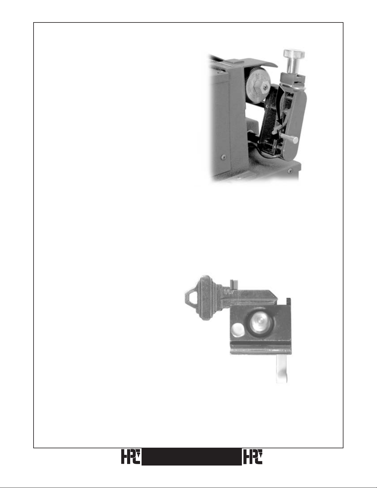
If you are using the Standard Model
CodeMax®, then the machine pauses at each
position and prompts you to manually rotate
the cutter head.
1. Pull the spring loaded Angle Index Pin
back.
2. Rotate the cutter head using the Pivot Pin,
to the “L” on the machine to make a left
Pull
Angle
Index
Pin
Pivot Pin
ROTATE CUTTER
HEAD NOW
angled cut, or to the “R” to make a right
angled cut.
3. Release the Angle Index Pin making sure it
is properly seated before proceeding to the
next cut.
4. Once the Cutter Head is properly
positioned, press “Enter” to begin the
next cut.
Cutting Medeco Standard Keys
Medeco Standard keys have an angle (Left, Right or Center) associated with each cut.
On the standard model CodeMax®, use DSD Number 51.
The machine will pause after each cut and prompt you to rotate the cutter head as needed.
For the Automatic Angler model, use DSD
Number 3051. The bittings screen has room
for 12 characters. Think of the 12 characters
as 6 sets of 2 characters each, one number for
the bitting and one letter for the direction of
the angle, to represent each cut on the key.
For example, the bitting of 324323 with the
first cut being a “Left” angle, the second a
“Right”angle, the third a “Center”, fourth a
“Left”, fifth a “Right” and sixth a “Left.”
Using the “B” key for Left, the “C” key for
Center and the “D” key for Right, the bitting
would be entered as:3L2R4C3L2R3L
32
CodeMax
®

Cutting Medeco Biaxial Keys
Medeco Biaxial keys utilize the Left, Right and Center angles and add the position of the angle:
“Fore” (the depth comes before the angle) or “Aft” (the depth comes after the angle). Medeco
designates the angles and positions as follows:
Medeco® Code Position & Angle
K Fore, Left
B Fore,Center
Q Fore, Right
M Aft, Left
D Aft, Center
S Aft, Right
On the standard model CodeMax®, use DSD Number 76.
The bitting screen will display 12 spaces to accommodate the position of the angle relative to the
depth on a 6-space key. This is accomplished by inserting a zero (0) (representing the position of
the angle) before the depth for an AFT cut or after the depth for a FORE cut. For example, a key
that reads:
D4 3B M5 D2 3K S2
aft fore aft aft fore aft
On the standard model CodeMax® it is entered as:
043005023002
The machine will pause at each position and prompt you to rotate the cutter head as needed.
4.1.3. Use of the CodeMax® AA Automatic Angler
On the Automatic Angler model, use DSD Number 3076.
The bitting screen will display 12 spaces to accommodate both the angle and the position.
The position is designated by the sequence it is input relative to the depth.
Medeco® Code Position & Angle DSD 3076 Buttons
K
B
Q
M
D
S
Use the “B” key for Left, the “C” key for Center
and the “D” key for Right.
To specify a 3-depth in the FORE position, with a
LEFT angle, enter the depth then the angle: 3L.
To specify a 5-depth, in the AFT position with a
RIGHT angle, enter the angle then the depth: R5.
Fore, Left
Fore, Center
Fore, Right
Aft, Left
Aft, Center
Aft, Right
Depth, then Left
Depth, then Center
Depth, then Right
Left, then Depth
Center, then Depth
Right, then Depth
CodeMax
®
33

Example: 3LR2C43LR23L
3L number 3 depth in the “Fore” position with a Left angle.
R2 number 2 depth in the “Aft” position, with a Right angle.
C4 number 4 depth in the “Aft” position with a Center or no angle.
3L number 3 depth in the “Fore” position with a Left angle.
R2 number 2 depth in the “Aft” position with a Right angle.
3L number 3 depth in the “Fore” position with a Left angle.
34
CodeMax
®

4.1.3 After The Key Has Been Cut
After the key has been cut you will have four options:
1) Press START to cut an additional key to the same bitting.
2) Press NEW CODE or CLEAR to enter a new bitting, using the same DSD.
Press CLEAR twice to enter a different DSD number.
3)
4) Press ENTER to autoload the next DSD number associated with a “Double-Sided
Different” key. If no autoload specifications are present, the CodeMax® will return to
the main screen.
5) Press CLEAR until you reach the main screen.
NOTE: At all screens you may press CLEAR to return to the previous screen.
CodeMax
®
35

4.1.4 Additional Notes
®
1) The CodeMax
from tip to bow. However, all bittings must be
always cuts shoulder-gauged keys from bow to tip, and tip-gauge keys
entered into the CodeMax
®
in bow to
tip order.
2)
If the original manufacturer (such as Kwikset) widens some or all of the cuts, the
CodeMax
®
will automatically do the same.
3) When cutting double-sided keys where there is a shoulder on only one side of the key,
or where the shoulders are not symmetrical (such as some VW keys), always cut the
shoulder gauged side of the key first, then press ENTER to cut the plain side.
Because most double-sided keys are
4)
back of the jaw, the recommended cutting
CodeMax
®
and then cut both sides of another
gauged by placing an uncut blade against the
procedure is to cut the first side on the
blank in a duplicator, using the code-cut
key as the original.
5) At all screens you may press CLEAR to return to the previous screen.
36
CodeMax
®

4.2 Computer Assisted Key Cutting
A personal computer that uses a Current Version of Windows® as its operating system, and
has authorized HPCSoft™ software products properly installed, can be connected to the
CodeMax® using a serial cable for computer assisted key cutting.
The CodeMax® cable (CABLE-25S) is a 25-foot serial cable designed for this purpose.
It is attached to the serial port on the computer and to the RS422 port on the back of the
CodeMax® . Refer to your computer manual to locate the serial port on the computer. For
computers without serial ports there are USB to serial adapters available at most computer
stores.
A single bitting may be downloaded from CodeSource® or KeyTrail
®
to the CodeMax®,
or as many as 250 different bittings from MasterKing® may be downloaded for master key
systems.
To download data from the computer, make sure the CodeMax® is in a clear condition. The
display will read:
Codemax Ready
HPCSoft Ver 10.0
Follow the instructions for each software program to send data to the CodeMax® . The
computer will then perform its handshake with the CodeMax® and download the data. The
display will read:
Making
Connection
Once the download transmission is complete, the CodeMax® may display an information
message about the incoming keys. This message will appear for approximately 2 seconds,
then the key bitting will appear at the Ready screen.
CodeMax
®
37

When downloading from MasterKing®, the first bitting appears at the Ready screen and
you may:
1) Press START to cut the key to the bitting displayed. Press START again to cut
additional keys to that bitting.
2) Press “C” (DOWN ARROW) to move forward through the key bittings.
3) Press “2” (UP ARROW) to move backward through the key bittings.
4) Press HOME (7) to change functions. For example, this feature may be used to
temporarily stop cutting keys for a master key system, so that one or more keys not
in the master key system may be cut. To return to the original function press ENTER,
then press HOME (7). The CodeMax® will resume from the point of interruption.
38
CodeMax
®

4.3 Micrometer Key Cutting
From the main screen press DSD#. The display shows:
Enter DSD Number
[ ]
Press “0” to signify that you wish to use the micrometer function of the CodeMax®. Press
ENTER and the display changes to:
Micrometer Key
Cutting Function
The display then changes to:
Enter Jaw Type
[ ]
Press A, B, or C to signify which jaw will be used. For our example, press A. The display
changes to:
Choose: A for In
B for mm
Press A or B to indicate the use of inches or millimeters for space and depth measurements.
For this example, press A for inches. The CodeMax® advances to the main micrometer
screen and the display shows:
Space 0.000 In
Depth 0.000 In
CodeMax
®
39

SPECIAL NOTE: To cut keys on the CodeMax® using the micrometer method you must use standard CodeMax® cutters
that have a center line of .188" and 2
require special calculations. The zero point for the Horseshoe Tip Stop is 1.215 and all spacing must be calculated from
this point. So, even if you are using a Tip Stop you must calculate spacings as though they were from a shoulder The zero
point for the Red Tip Stop is .940" and all spacing must be calculated from this point.
3⁄
8" diameter. Keys may be gauged from either the shoulder or the tip. Tip gauged keys
You must indicate that the first cut is to be measured from the shoulder of the key to the
right. Press “8” (>). The following display appears:
Space 0.000 In>
Depth 0.000 In
The arrow to the right of the spacing display line (>) confirms that the first cut is to be to
the right of the shoulder of the key. After setting the direction, set the spacing value from
the shoulder to the first cut. For our example, the value is .231, so press “2”, “3”, “1”, then
press ENTER. The display changes to:
Space 0.231 In>
Depth 0.000 In
Press START and the CodeMax® aligns the Pivot Arm for the first cut. When the
CodeMax® stops, press “2” (UP ARROW) to signify that the Pivot Arm will be moving up
into the cutter. The display shows:
Space 0.231 In
Depth 0.000 In^
40
CodeMax
®

Next, indicate the depth of the first cut. Our example requires a depth of .290. Press “2”,
“9”, “0”, then press ENTER. You will see the following display:
Space 0.231 In
Depth 0.290^ In
Press start to make the cut. Notice that the CodeMax® stays in the cut position and the
cutter continues to spin. This allows you to widen the cut, if necessary, by using the space
commands. Press HOME (7) to ready the machine for the next cut.
Review Of Micrometer Key Cutting Procedures
Let’s quickly review the basic steps required:
1) Press “8” (>).
2) Set spacing numbers from shoulder to first cut, then press
ENTER.
3) Press start to activate spacing stepper motor.
4) Press “2” (up arrow).
5) Enter depth numbers.
®
6) Press start for the CodeMax
to make the cut.
7) Repeat steps 1, 2, and 3 if the cut has to be widened. If the cut does not have to be
widened, press Home (7) to return to the home position.
CodeMax
®
41

Final Micrometer Key Cutting Procedures
We will now continue with cutting an example key using the Micrometer Key Cutting
Procedure.
Press “8” (>) to set the direction from the shoulder of the key.
Next, enter the cut-to-cut spacing. For our Schlage example, this is .156. Press “1”, “5”,
“6”, then press ENTER and START. Notice that the carriage does not move to “.156”, but
to “.387”. The CodeMax® totals the distances of our first and second cuts (.231 + .156 =
.387) and the display shows the real location, 0.387.
Remember, the cutter wheel does not move laterally. Only the carriage holding the key
blank moves. To position the cutter to the right of the shoulder at a designated spacing,
the carriage moves to the left. Do not let this confuse you as you watch movements for
spacings.
Next, indicate the direction and depth of the cut. For our example, press “2 (up arrow) to set
the direction (the carriage moves up to the cutter), then press “2”, “4”, and “5” (the depth of
the cut is .245). Press ENTER and START to make the cut. When the cut is complete, press
HOME in preparation for the next cut.
Now that you have the hang of things, repeat steps 1 through 7 until all of the cuts are
made. Once the key is complete, press CLEAR to return to the main screen.
42
CodeMax
®

5. Recalibration Of The CodeMax
5.1 Electronic Calibration
The CodeMax® is capable of Electronic Calibration. Minor depth and space adjustments,
as well as DSD Specific Depth adjustments, can be performed using the CodeMax® keypad
and stored in the CodeMax® CPU board. These adjustments can be used to offset normal
wear and tear on the machine, or after replacing or sharpening cutters.
DSD Specific adjustments allow you to make minor depth adjustments to accommodate
worn locks or keys or special applications.
®
CodeMax
®
43

5.1.1 Depth Instructions
Total Machine adjustments affect all DSD’s including keys downloaded from software. To
make Total Machine electronic Depth Adjustments on the CodeMax® start with the “LOAD”
button.
Press “LOAD”
Enter “CC” and press the “ENTER” button
Choose between Inches and Metric.
“A” for Inches and “B” for Metric
Choose: A for in
B for mm
Choose Depth or Space adjustment.
“A” for Depths and “B” for Space
Use: A for Depth
B for Space
If Depths were chosen the screen will read:
Depth Adjustment
0.000 In
44
CodeMax
®

Use the Up Arrow (2) keypad button or the Down Arrow (C) button to change the Depths.
The Display will show how much of an adjustment you are making.
Use the “ENTER” button when you are done.
Depth Adjustment
0.025 In
Press “A” to proceed out of the Adjustment screens or “B” to return to the Depth
Adjustment screen.
Confirm 0.000 In
A=Yes B=No
Depth Adjustment Confirmation Screen will flash twice indicating the adjustment has been
saved. The CodeMax® now returns to the Main menu and is ready to use.
(Although the adjustment will not be shown next time you access machine adjustments,
CodeMax® saves the adjustment in memory even after power has been turned off.)
CodeMax
®
45

5.1.2 Space Instructions:
Total Machine adjustments affect all DSD’s including keys downloaded from software. To
make Total Machine electronic Space Adjustments on the CodeMax® start with the “LOAD”
button.
Press “LOAD”
Enter “CC” and press the “ENTER” button
Choose between Inches and Metric.
“A” for Inches and “B” for Metric
Choose: A for in
B for mm
Choose Depth or Space adjustment.
“A” for Depths and “B” for Space
Use: A for Depth
B for Space
If Space was chosen “Space Adjustment” will flash twice and bring you to the next screen.
You can choose “A” for Shoulder adjustment and “B” for Black Tip Stop adjustment.
Use: A=Shoulder
B=Black tip
46
CodeMax
®

Increase .000 ^ (no previous adjustments should be displayed)
Decrease .000 v
Use the Up Arrow (2) keypad button or the Down Arrow (C) button to change the Space.
The Display will show how much of an adjustment you are making. Use the "ENTER"
button when you are done.
Confirm +.000
A=Yes B=NO
(auto enter)
("No" returns to adjust screen)
Space Adjustment ***FLASH for 1 second***Saved +.000
Press ”A” to proceed out of the Adjustment screens or “B” to return to the Space adjustment
screen.
Space Adjustment Confirmation Screen will flash the adjustment and that it has been saved.
The CodeMax® now clears and reinitializes completing the Space adjustment.
CodeMax
®
47

5.1.3 DSD Specific Instructions:
Use the “DSD” button and enter the DSD you want to adjust.
After displaying the DSD name and gauge point the “Bitting Window” appears.
Enter a bitting and hit the “ENTER” button.
Once at the “Ready Screen” press the “LOAD” button to access the DSD Specific Depth
adjustment.
Note: A previously adjusted DSD will add “**ADJ**” on the top line of the display.
Ready...**ADJ**
[52354]
This DSD can be used as is or adjusted again
After hitting “LOAD” the following message will be on the screen.
“Depth Adjustment”
0.000 In
Any previous adjustments will be displayed here.
Use the Up Arrow (2) keypad button or the Down Arrow (C) button to change the Depths.
The display will show how much of an adjustment you are making. Use the “ENTER”
button when you are done. To clear any previous adjustments just follow the above
instructions until the display reads “0.000 In”
48
®

Press “A” to proceed out of the Adjustment screens or “B” to return to the Depth
adjustment screen.
Confirm 0.000 In
A=Yes B=No
Depth Adjustment Confirmation Screen will flash twice indicating the adjustment has
been saved.
You will now return to the “Ready...**ADJ**” screen and cut your key with the new
adjustment. As long as the adjustment is stored all keys cut with this DSD will be
offset by the selected amount.
CodeMax® CodeMax
49

5.2 Manual Calibration
The Electronic Adjustment Function is suitable for making minor adjustments.
Manual Calibration will be required if the carriage is replaced or is accidentally moved
significantly out of position.
I. Space Calibration
No readjustment of space is required when changing from one depth and spacing
specification to another. The information sent by the DSD number or computer positions
the correct lateral alignment when using factory cutters. The need to readjust the space is
rare and should be attempted only after the more common causes for miscut keys have been
eliminated.
Remember, when originating a key by code, quite often, code numbers are misread. Locks
can sometimes be coded incorrectly when they are new, and code books occasionally have
typographical errors. All this distracts from successful cutting of keys by code.
You may proceed after eliminating the above mentioned causes for miscut keys and
checking for correct depth calibration.
50
CodeMax
®

5.2.1 Cutting Too Close To The Tip (On Keys Gauged From The Tip Stop)
Fig. 1
Tools required: 5/64" Allen wrench, factory cut key, rubber or rawhide mallet.
1) Select a tip-gauged, factory cut large cylinder type key, such as Best, Falcon, or Ford.
Make sure that all cuts are deeper than a #1 depth.
2) Install the correct cutter wheel.
3) Turn on the CodeMax
®
.
4) Select and enter the proper Depth and Spacing Data number.
5) Enter in all #1 cuts for the depths. Then press ENTER
to accept, and then press START
to begin the cutting process.
6) The CodeMax® will start to travel laterally towards the key. When the machine travels
to the first cut (closest to the tip) and the key begins traveling towards the cutter
(making depth cut), push the emergency stop button.
7) Check to see if the cutter is in the center of the cut (see Fig. 1).
8) If the cutter is too close to the tip of the original key, use a 5/64 inch allen wrench to
loosen the four set screws on the lower inside and bottom of the pivot arm
(CM-1024X).
CodeMax
®
51

Fig. 2
Fig. 3
9) With a small rawhide or plastic mallet, lightly tap the lower, left side of the Pivot Arm
until the pin seat of the cut is directly opposite the flat of the cutter (see Fig. 2). With
the cutter aligned opposite the cut, retighten the set screws (see Fig. 3).
10) Release the Emergency Stop Button. The Pivot Arm will return to the
Note: You may have to recalibrate the Shoulder Gauge after recalibrating the Tip Gauge.
52
CodeMax
®
HOME position.

5.2.2 Cutting Too Far From The Tip (On Keys Gauged From The Tip Stop)
Fig. 1
1) Select a tip-gauged, factory cut large cylinder type key, such as Best, Falcon, or Ford.
Make sure that all cuts are deeper than a #1 depth.
2) Install the correct cutter wheel.
®
3) Turn on the CodeMax
.
4) Select and enter the proper DSD number.
5) Enter all #1 cuts for the depths. Then press ENTER
to accept, and then START to
begin the cutting process.
6) The CodeMax
®
will start to travel laterally towards the key. When the machine travels
to the first cut (closest to the tip) and the key begins traveling towards the cutter
(making the depth cut), push the Emergency Stop Button.
7) Check to see if the cutter is in the center of the cut (see Fig. 1).
CodeMax
®
53

Fig. 2. Loosen four (4) set screws
Fig. 3. Lightly tap inside of carriage arm.
8) If the cutter is too far from the the tip of the original key, use a 5/64 inch allen wrench
to loosen the four set screws on the lower inside and bottom of the Pivot Arm
(CM-1024X) (see Fig. 2).
9) With a small rawhide or plastic mallet, lightly tap the inside of the Pivot Arm to move
the cutter closer to the top of the key while centering the cutter flat with the pin seat
(see Fig. 3).
10) Release the Emergency Stop Button. The Pivot Arm will return to the Home position.
Note: You may have to recalibrate the Shoulder Gauge after recalibrating the Tip Gauge.
54
CodeMax
®

5.2.3 Cutting Too Far From The Shoulder
Note: Only recalibrate the shoulder gauge after being sure that the tip gauge is properly
calibrated.
1) Select a shoulder gauged, factory cut type key, such as a Schlage or Arrow. Check to
see that the #1 space (closest to the shoulder) is greater in depth than a #1 cut.
2) Install the correct cutter wheel.
®
3) Turn the CodeMax
on.
4) Select and enter the proper DSD number.
5) Enter in a #1 cut for the depth. Then press ENTER
to accept, and press START to
begin the cutting process.
6) The Pivot Arm will start to travel laterally towards the key. When the Pivot Arm travels
to the first cut (closest to the shoulder) and the key begins traveling towards the cutter
(making the depth cut), push the Emergency Stop Button.
7) Loosen the key in the jaw. Slide the key to your right until the pin seat of the cut is
directly opposite the flat of the cutter. Tighten the key in the jaw.
8) Release the Emergency Stop Button to allow the machine to return to the Home
position.
CodeMax
®
55

Fig. 1
Fig. 2
9) Loosen the set screw that holds the Turn Bar in place in the Pivot Arm. See Fig. 2.
Swinging the Shoulder Gauge should also rotate the Turn Bar.
Note: If the Turn Bar does not rotate, squirt some WD-40, or equivalent, on the threaded end.
Then work it loose by simultaneously swinging the Shoulder Gauge and rotating the Turn Bar
(see Fig. 1).
10) Swing the key Shoulder Gauge down to release the Turn Bar. Then, firmly gripping
the right end of the Turn Bar so that it remains stationary, swing the key Shoulder
Gauge up against the key. The Shoulder Gauge should be just touching the shoulder of
the key. Now, without rotating the Turn Bar anymore, tighten the set screw that holds
the Turn Bar (see Fig. 2).
56
CodeMax
®

5.2.4 Cutting Too Close To The Shoulder
Note: Only recalibrate the Shoulder Gauge after being sure that the Tip Gauge is properly
calibrated.
Swing
Shoulder
Gauge
Turn Bar
Turn Bar Set Screw
Fig. 1
1) Select a shoulder gauged, factory cut original large cylinder type key, such as a Schlage
or Arrow. Check to see that the #1 space (closest to the shoulder) is greater in depth
than a #1 cut.
2) Install the correct cutter wheel.
®
3) Turn the CodeMax
on.
4) Select and enter the proper DSD number.
5) Enter in a #1 cut for the depth. Then press ENTER
to accept, and then press START to
begin the cutting process.
6) The Pivot Arm will start to travel laterally towards the key. When the Pivot Arm travels
to the first cut (closest to the shoulder) and the key begins traveling towards the cutter
(making the depth cut), push the Emergency Stop Button.
7) Loosen the key in the vise. Slide the key to the left to line up the cutter flat opposite
the pin seat. Tighten the key in the jaw.
8) Release the Emergency Stop Button to allow the machine to return to the Home
position.
9) Loosen the set screw that holds the Turn Bar in place in the Pivot Arm. Swinging the
Shoulder Gauge should also rotate the Turn Bar.
Note: If the Turn Bar does not rotate, squirt some WD-40, or equivalent, on the threaded end.
Then work it loose by simultaneously swinging the Shoulder Gauge and and rotating the Turn
Bar. (See Fig. 2)
CodeMax
®
57

Swing Shoulder
Gauge
Rotate Turn
Bar
Fig. 2
10) Swing the key Shoulder Gauge down to release the Turn Bar. Then, firmly gripping the
right end of the Turn Bar so that it remains stationary, swing the key Shoulder Gauge up
against the key. Rotate the Turn Bar to the desired position and hold it there. The Shoulder
Gauge should just touch the shoulder of the key (see Fig. 2). Now, without rotating
the Turn Bar any more, tighten the set screw that holds the Turn Bar.
58
CodeMax
®

5.3 Depth Adjustment
Fig. 1
The need to readjust depth is caused by cutter wear or cutter replacement It is easily
accomplished by rotating the eccentric shaft (CM-1041) with the 3/8 inch end of
WRENCH-1, turning towards you to cut deeper, and away from you to cut shallower. The
180 degree rotation allows depth adjustments of plus or minus .015 inch. Since the eccentric
shaft is made of drill rod, there is no need to loosen the two binding screws prior to rotating
it (see Fig. 1).
Tools Required: Key Micrometer or Caliper, Key Blanks, Correct Depth and Spacing Data,
WRENCH-1 (use 3/8 inch end for depth adjustment).
®
1) Install a key blank in the CodeMax
®
2) Turn the CodeMax
on.
jaw.
3) Select and enter the proper DSD number (e.g. 60 for Schlage Large Pin).
4) Enter the depths, press ENTER
to accept, and press START to begin the key cutting
operation.
5) After the key has been cut, use a micrometer or caliper to measure the depth cut and
compare it against the Depth and Spacing specifications chosen in step 3 above. If
the reading of the micrometer is the same as the Depth and Spacing specifications, the
machine is cutting correctly. If the cuts are higher or lower, adjust the Eccentric Shaft
as explained in the beginning of this section (see Fig. 1). When checking the calibration
on a key machine, it is very important to use the proper tools in order to maintain the
accuracy of the machine. A key micrometer or caliper is a small investment and is
highly recommended to acquire the greatest accuracy.
CodeMax
®
59

6. Updates
Updates to the CodeMax® are now performed using your PC and a
CD supplied by HPC, Inc. Connect the Serial Cable (included with
CodeMax®) to the correct Com Port on your PC and the RS422
port on the back of the CodeMax®. Follow the directions that come
with the CD to update your CodeMax®. It is no longer necessary to
open any part of the CodeMax® to perform updates.
Program name: Update.exe
To start, double click the desktop shortcut
Update or, in My Computer, open your C: drive, open the Program Files folder, open the HPCSoft™ folder, open the
CodeMax® Update folder, double click Update.exe (application).
Make sure your serial cable is connected to the back of the CodeMax
®
To update your CodeMax
Status will display progress: Waiting for Load Command, Waiting for STX, Sending Data (514 bytes, 1, 2, etc.), Waiting
for ACK, Send Complete. During the update process, CodeMax® screen will display “Starting Upgrade **Please Wait**”.
CodeMax® will beep when the update is completed.
If the new update information does not appear in CodeMax
files.
®
If CodeMax
screen remains dark after Send Complete, use the following correction procedure:
1. Turn off your CodeMax® , leave off until
instructed below.
2. On your computer, open
3. Open the
4. Open the Program Files folder.
5. Open the HPCSoft folder.
6. Open the CodeMax
7. LEAVE THE CodeMax
8. In HPC CodeMax
Program.
9. Click
10. When Status reads “Waiting for STX”, turn
ON CodeMax
11. CodeMax
download.
If your CodeMax
Key Machine Services.
does not beep on completion of the update process, or if the update process is interrupted, or if the CodeMax®
C: drive.
Start Update
®
®
operating instructions will
®
, click on the Com Port to which CodeMax® is connected and click Start Update.
My Computer
®
Update folder
®
TURNED OFF!
®
Update Program, click
.
fails to start after this procedure, contact HPC
CodeMax® Update, or click Start, Program files, HPCSoft™ and CodeMax®
®
.
®
, repeat the update process. Be sure you are using the latest
60
CodeMax
®

7. Troubleshooting
Problem: The CodeMax® is turned on but nothing appears on the display screen and the
internal stepper motors do not start.
Solution: Check the cord, fuse, and the available power supply.
®
Problem: The CodeMax
is turned on but all that appears on the display
screen are square blocks.
Solution: Remove the Key Pad from the casting. This problem is most often associated
with a shorted keyboard wire against the casting. Once the keyboard has
been removed from the casting, attempt to turn on the machine again. If the
screen starts normally, inspect the keyboard wire or call HPC to obtain a new
keyboard wire.
®
Problem: The stepper motors jam while using the CodeMax
.
Solution: Try turning off the CodeMax® for a few seconds to clear the memory, then
turn it back on to reset the machine. If this does not clear the jam, consult
factory assistance.
Problem: Keys are not being cut accurately.
Solution: Check three possibilities: Either your cutter wheel is dull (or not the proper
diameter), the machine is out of adjustment, or the cutter belt is loose.
Attempt to cut the key utilizing the micrometer function. If the keys cut
utilizing the micrometer function are also not accurate, the machine probably
requires adjusting. Make sure the belt is snug (not overtight) and see Section
5: Recalibration of CodeMax®.
®
Problem: The CodeMax
is turned on but the stepper motors produce a grinding sound,
like they have crashed into the casting.
Solution: Turn off the machine (several electronic switches may have gone bad). Under
these conditions you should consult factory assistance.
In the event that this troubleshooting section does not solve your problems, or
you have any additional questions, call the HPC Service Center:
800.323.3295
847.671.6280
Monday-Friday
8:00am-3:30pm Central Time
CodeMax
®
61

8. Glossary
Autoload:
The downloading of information from compatible software packages.
CodeMax®:
HPC’s computerized code machine.
Contour Cutting
The carriage moves laterally across the cutter, producing a key with no peaks between cuts.
Depth:
Measured in thousandths of an inch or hundredths of a millimeter. Refers to y-axis cutting
on the CodeMax®. Also, a measurement from the bottom of the key to the root of the cut.
Emergency Stop Button:
A red button in the front of the CodeMax® used for stopping all machine movements.
Jaw:
The vise that holds the key in position for cutting on the CodeMax® or any other machine.
Jaw Type:
Denoted by the letters A, B, or C. Indicates the proper jaw used for cutting a specific key.
Plain Side
The flat side of the key which faces towards the cutter when properly positioned for cutting
(the gauging point for this type of key is referred to as a Left Side Jaw Gauge).
Series:
A set of numbers within a given range, which refers to a key code number.
:
:
Shoulder Gauge:
Used to gauge standard cylinder and automotive keys. (Refer to section 3.3).
Shoulder Side
The non-flat side of the key which faces towards the cutter when properly positioned for
cutting (the gauging point for this type of key is referred to as a Shoulder Gauge).
Speed Adjustment
Increase or decrease rate of feed in the y-axis or depths.
62
:
:
CodeMax
®

Tip:
The end of the key that enters the lock first. Also, certain keys may be gauged utilizing
the tip of the key (the gauging point for this type of key is referred to as Red Tip Stop or
Horseshoe Tip Stop gauging).
Tip Gauge
:
Used to gauge keys with no shoulders. (Refer to section 3.3)
Widen Cut
:
On keys such as Kwikset, Weiser, Volkswagen, etc. the x-axis (or spacing) often needs to be
widened more than the standard cutter wheel allows. In this manual, this is usually referred
to as general widening or specific widening. This is a function that is specified by the
manufacturer and performed automatically by the CodeMax®.
CodeMax
®
63

9. Exploded Views
Pivot Arm With Safety Switch Assembly
# Description Stock #
1. Easy Grip Wing Nut EGN-1
2. Ball Bearing Washer BBW-2
3. Top Jaw CM-1056MA
4. Spring CM-1293MA
5. Stud CM-1019MA
6. Ball Bearing CM-50108
7. Set Screw CM-50110
8. Bottom Jaw (factory installation recommended) CM-1055MA
9. Tip Stop CM-1054MA
10. Spring CM-1090MA
11. Set Screw CM-50139
12. Eccentric Shaft CM-1041
13. Set Screw CM-50109
14. Set Screw CM-50112
15. & 16 Turn Bar & Shoulder Gauge CMB-FG
17. Retaining Ring CM-50105
18. 2-56 Screw MAX-92
19. Shoulder Gauge Wire Assembly MAX-90
20. Shoulder Gauge Micro Switch Bracket MAX-91
21. 6-32 Set Screw MAX-89
64
CodeMax
®

CodeMax® Pivot Arm with Safety Switch Assembly
CodeMax
®
65

CodeMax® Parts List
# Description Stock #
1. Keypad MAX-4
2. Pad Locator MAX-5
3. Keypad Display Circuit Board MAX-6
4. Pivot Arm Assembly CM-1024X
5. Cutter Head Assembly CM-1053X
6. Grip Spring CM-1079
7. Belt Guard CM-1014B
8. Angle Index Pin CM-1042
9. Belt CM-1083MA
10. Motor Pulley CM-1060MA
11. Set Screw 9100-11
12. Nut CM-50148
13. Screw CM-50158
14. Motor Mounting Bracket CM-1040MA
15. Hex Nut CM-50157
16. Screw CM-50167
17. Motor CM-1080MA
18. Pivot Pin CM-1043
19. Washer CM-50100
20. Power Cord MAX-34
21. Screw MAX-35
22. Plunger U-Bracket MAX-43
23. Display Board Wire Assembly MAX-44
24. Screw #8-32 x 1/4 MAX-46
25. Gasket MAX-47
26. Rubber Bumper CM-50133MA
27. Screw CM-50134
28. Amp Fuse MAX-78
29. Washer CM-50167-1
30. Motor Support CM-50186
31. Motor Support Screws (2) CM-50188
66
Circuit Connections
A1 connects to: A
B1 connects to: B
C1 connects to: C
D1 connects to: D
E1 connects to: E
F1 connects to: F
G1 connects to: G
H1 connects to: H
J1 connects to: J
CodeMax
®

2
CodeMax® Primary Assembly and Circuit Connections
CodeMax
®
67

10. Preventive Maintenance, Lubrication,
Repairs, and Warranty
1) WARRANTY — The CodeMax® Code Machine is fully warranted for one year from the
date of purchase, against factory defects in material and workmanship. Mail the Warranty Card
and a copy of your invoice immediately, to validate your warranty. Should your machine require
factory repairs, please contact the Key Machine Service Department before returning your machine.
During the one year warranty period, you will be billed for handling and shipping only.
2) MOTOR — The motor is equipped with sealed bearings that require no lubrication.
3) CUTTER HEAD — The cutter head is equipped with precision ball bearings for years of
trouble free service and requires no lubrication. The cutter head swivel surface and plunger
angle holes should be given a light coat of LPS#3 or equivalent, once every four to six months.
4) BEARINGS AND SLIDING SURFACES — These are to be given a light coat of a light grease
at least every six months.
5) EXPOSED STEEL SURFACES — All remaining exposed steel shafts, cutters, etc., should be
sprayed with WD-40 or equivalent light oil at least every six months. Wipe off any excess.
6) CLEANING — Remove all brass chips, dirt, and grit from the surface of your machine daily,
with a soft bristle brush. Take particular care in keeping the jaw area clean and free of all
residue build-up.
7) CALIBRATING DEPTH FOR RESHARPENED CUTTERS — Sharpening cutters changes
the diameter; HPC, Inc. recommends replacing cutters instead of sharpening. The diameter of
a resharpened cutter is smaller and therefore will make cuts shallower (if no depth adjustment
is made). In order to maintain matched cutter diameters, all cutters for this machine must be
resharpened at the same time, and all diameters must be sharpened proportionately.
8) DRIVE BELT — The drive belt (CM-1083MA) was selected especially for this machine and
should give years of good service. If it becomes worn or broken and requires replacement, be
sure to install the new belt with the teeth outward.
Note: The drive belt is somewhat more noisy when it is made to “cross-over” as the cutter head
is swiveled to either the left or right angle when cutting Medeco®keys.
HPC Key Machine Service Dept.
Tel: 800.323.3295 (USA & Canada)
Tel: 847.671.6280
Monday-Friday
8:00 - 3:30 Central Time
68
CodeMax
®

HPC SERVICE CENTER
If your HPC Key Machine should require service, please note the following information:
HOURS: The HPC Service Center answers questions involving key machine repair and replacement parts Monday
through Friday from 8:00 am to 3:30 pm Central time.
Please call 800-323-3295 (from the U.S. and Canada) or 847-671-6280 (from other countries).
REPAIRS: We recommend the replacement of cutters, brushes and external parts, the preventive maintenance and
recalibration (as outlined in this manual) be the only repairs or adjustments that are done by the user. Internal parts and
mechanisms should be factory-repaired only. Additional repair charges may be incurred by attempting to make these
types of repairs by yourself.
FACTORY SERVICE: If you need to send your HPC key machine in for repair, first call the HPC Service Center
to obtain a Repair Order number, then follow these instructions:
Include a letter explaining the problem you are having, as well as any other work you want done on the machine. Make sure
your business name, address and phone number, as well as the name of the contact person are on the letter.
Your machine should be equipped with an HPC cutter when it is sent in for repairs. If you are sending in a Blitz™ or
CodeMax™ machine also include the Black Horseshoe Tip Stop to insure proper tip gauge calibration. Please do not send in
any other accessories (such as other cutters and code cards).
Pack the machine securely in a box strong enough to prevent damage during shipping (preferably the original box).
The Repair Order Number should be marked on the outside of the box.
All machines must be shipped prepaid. Collect shipments will not be accepted.
Our shipping address is:
HPC, Inc.
Attn. Service Center
3999 N. 25th Avenue
Schiller Park, IL 60176 USA
REPAIR CHARGES & ESTIMATES: Upon receipt and evaluation of your machine our technicians will
provide a written estimate (by fax) of the repair charges. Some problems may be detected only while the repair work is being
done. If after informing you of the repair estimate it becomes apparent that the cost will be higher, you will be notified of the
additional charges before any additional work is done.
REPLACEMENT PARTS: Key machine parts can be purchased through an Authorized HPC Distributor or
directly from the HPC Service Center. When ordering parts over the phone, please have the part numbers and descriptions
ready to expedite the ordering process. A parts listing and an exploded view drawing is included in this manual. If the parts
are needed urgently, express processing is available at an additional charge.
PAYMENT: Payment for parts and repair is required at the time of repair and before the parts are shipped. We accept
payment by credit card (Visa, Mastercard or Discover) or by check. Repaired machines and parts can also be sent C.O.D.
with an extra charge. If you wish to have your Authorized HPC Distributor billed for the parts or repairs, the distributor must
call us with approval of the billing and provide a purchase order number for the parts or work being done, before the machine
is repaired or parts are shipped.
Unless otherwise specified, key machines that are not under warranty will be shipped C.O.D. with an extra charge after the
repairs have been made.
LOANER MACHINES: Sorry, but we do not have loaner machines available.
CodeMax
®
69
 Loading...