

Owner’s Manual
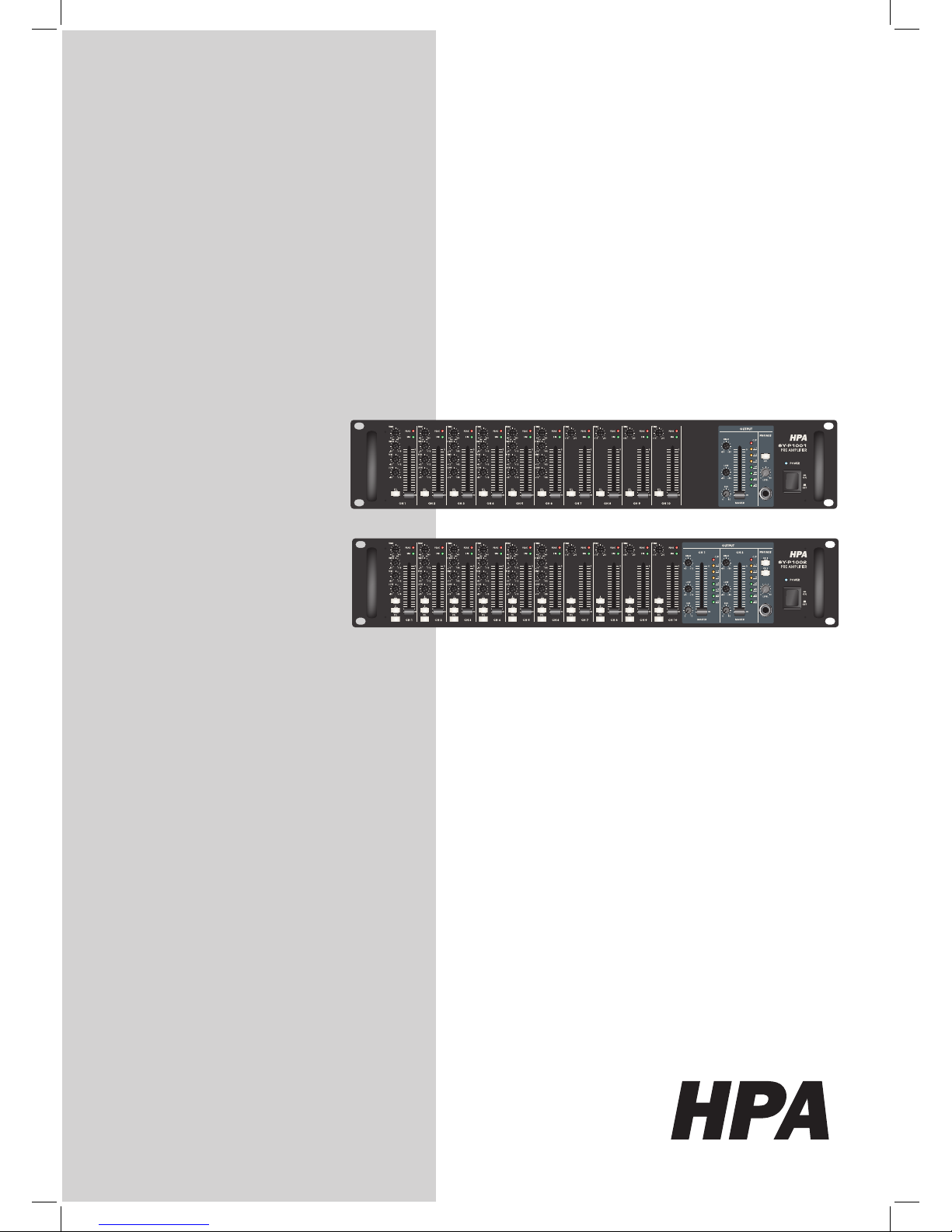
SY-P1001
SY-P1002
WARNING

1
SY-P1001 / SY-P1002
Introductions ……......................………………………………………….2
Features ……….......................……………………………………………3
Front panel controls ....…...................…………………………………..4
Rear panel controls ......................………………………………………6
Connections …....…................……...……………………………………8
Block diagram ……....................………………………………………11
Specifications …...................………………………………………….12
Table of Contents
Table of Contents
2
SY-P1001 / SY-P1002
Introduction
Welcome
Congratulation and thank you for purchasing SY-P series
Unpacking and Installation
Although it is neither complicated to install nor difcult to operate Pre Amplier, a few minutes of
your time is required to read this manual for a properly wired installation and becoming familiar
with its many features and how to use them.
Please take a great care in unpacking your set and do not discard the carton and other packing
materials. They may be needed when moving your set and are required if it ever becomes nec-
essary to return your set for service. Never place the unit near radiators, in front of heating vents,
excessive humid or dusty location to avoid early damage and for your years of quality use.
Connect your unit with the system components according to the description on the following
pages.
SY-P1001 / SY-P1002
Introductions

3
SY-P1001 / SY-P1002
Features
Features
* Versatile function and compact size
* 6 Channels MIC input with XLR jack
* 10 Channels LINE input with 1/4” phone jack
* 4 Channels LINE input with RCA jack
* 3 Band EQ control on every MIC channels
* Acceptable wide range input level with trim pot
* Useful monitoring function on the whole input and output channels with PFL/AFL switches.
* 2 Band EQ control on every output channels
* Signal and peak indicator on each input channels.
* DC+18V phantom power for condenser microphone on the MIC channel 1 and 2
* Useful ducking function on the MIC channel 1 and 2
* 1 Priority input channel for emergency announcement
* 2 Insert channels allow connecting external effecter
* Multi channel output as 2 main output, 2 sub output and 2 record output
* Useful slide fader for each input level and main output level
* Runs on 100-120VAC, 220-240VAC and 24VDC for evacuation orders.

4
SY-P1001 / SY-P1002
Controls
Controls
1
5 7
2 3 4 8 11 13 16
9 10 12 15 14 17
1 2 3 4 88 1112 1112 13 16
5 6 7 9 10 9 10 15 14 17
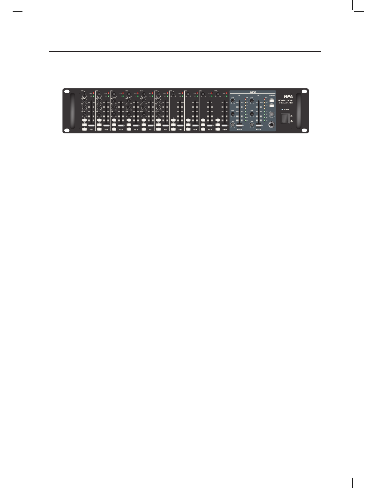
[ Pig.1-SYP1001 FRONT ]
[ Pig.2-SYP1002 FRONT ]
Front Panels
1. TRIM CONTROLS
These controls allow accept variable input level.
They have 44dB adjustable range as - 60dB to
-16dB for microphone level and -30dB to +14dB for
line level.
2. SIGNAL INDICATORS
These indicators show present input signal on the
each input channels.
3. PEAK INDICATORS
These indicators warn against clipping shortly on
the each input channel.
HPA recommend for users to adjust TRIM control
when PEAK indicator is ickering to make best
performance.
4. INPUT CHANNEL FADER
These faders allow level adjust for each input
channel.
5. INPUT CHANNEL EQ CONTROLS
6 MIC input channels have 3 bands equalizer
which is adjustable over a wide range.
6. OUTPUT CHANNEL SELECTORS
These selectors allow each input signal through
out to selected output channel.
This function is in SY-P1002 only.
7. PFL SWITCHES
This switch allows you to monitor the pre-fader
signal of input channel through headphone output.
8. OUTPUT CHANNEL EQ CONTROLS
Output channels have 2 bands equalizer which is
adjustable over a wide range.
9. SUB OUTPUT LEVEL CONTROLS
These controls allow level adjust for sub output
channels.

5
SY-P1001 / SY-P1002
10. OUTPUT CHANNEL FADER
These faders allow level adjust for main output
channels.
11. CLIP INDICATORS
These indicators warn against clipping shortly on
the each output channel.
HPA recommend for users to adjust output fader
when CLIP indicator is ickering to make best
performance.
12. OUTPUT LEVEL METERS
These indicators show output signal level.
13. AFL SWITCHES
This switch allows you to monitor the main output
signal of output channel through headphone
output.
14. HEADPHONE LEVEL CONTROL
This control allows you adjust the signal level of
headphone output
15. HEADPHONE JACK TERMINAL
HPA recommend for users to use a standard
6.3mm (1/4”) jack for connection of headphones.
Pig.3 shows proper headphone plug for standard
6.3mm (1/4”) jack.
16. POWER INDICATOR
This indicator shows power on/off status.
17. POWER SWITCH
Device will be supplied power when this switch is
pressed and locked.
Controls
Front Panels
(1/4" Phone 3 Section Connector)
( O )
(1/4" Phone 2 Section Connector)
( X )
[ Pig.3-HEADPHONE PLUG ]

6
SY-P1001 / SY-P1002
Controls
Controls
1
1 3 4 6 8 10 11
2 5 7 9
2 5 7 9
3 4 6 8 10 11
[ Pig.4-SYP1001 REAR PANEL ]
[ Pig.5-SYP1002 REAR PANEL ]
Rear Panel
1. DC 24V INPUT AND LINK OUTPUT
Device will be supplied DC 24V through input
terminal and supply to other device through link
output terminal.
2. AC INLET
This AC inlet allows replacing fuse conveniently.
Please make sure the value of fuse before replacement.
3. CHANNEL INSERT
These insert jacks allow connecting external effectors like compressor, limiter, noise lters.
HPA would like to recommend using proper insert
cable as below Pig.6
Tip:Output(Send to external device)
Sleeve:Ground
Ring:Input(Return from external device)
4. SUB OUTPUT
Sub output channel is prepared for sub amplier.
5. MAIN OUTPUT
Main amplier will be connected to this output
terminal.
6. PRIORITY INPUT
Whole other input signals will be muted automatically by priority input signal.
This terminal will be used to evacuation announcement.
7. RECORD OUTPUT
This terminal allows recording with tape recorder.
8. LINE INPUTS
These line inputs can be connected line level
equipments.
This device allows connecting 6 balanced(CH1-6)
and 4 unbalanced(CH7-10) inputs.
[ Pig.6-INSERT CABLE ]

7
SY-P1001 / SY-P1002
Controls
Rear Panel
Also allow adjusting level with TRIM pot of front
panel to accept variable input sources.
9. MICROPHONE INPUTS
This device allows connecting 6 balanced microphone input with acceptable wide impedance range
from 50ohm to 600ohm.
10. PRIORITY SWITCHES
These switches allow talk over for MIC channel 1
and 2. All other input signals except priority input
channel are muted when this function is activated
during press.
MIC channel 1 and 2 have same priority grade
as priority input channel during these swithes are
pressed.
11. PHANTOM POWER SWITCHES
This device supply DC+18V phantom power to use
condenser microphone with MIC1 and 2 channels.

8
SY-P1001 / SY-P1002
Connections
HPA products are wired to reect accepted wiring practices used throughout the world.
Balanced XLR connectors are wired as described:
Pin #1 Shield
Pin #2 Positive
Pine #3 Negative
Balanced 1/4” TRS connectors are wired as described:
Tip is Positive
Ring is Negative
Sleeve is Shield
Connections
Insert Points
A
mp/Line Input
Headphones
Unbalanced
Input/Output
AUX Send
Ring
Ring
Tip
Tip
Sleeve
Sleeve
Send
Return
Screen
Hot (positive)
Cold (negative)
Screen
Left Signal
Right Signal
Ground
Signal
Ground
3 Pole (Stereo) Jack
2 Pole (Mono) Jack
Ring TipSleeve
TipSeeve
2
1
3
Balanced Input
Hot (positive)
Hot (positive)
Sleeve
Screen
Cold (negative)
Cold (negative)

9
SY-P1001 / SY-P1002
Connections
CONNECTOR AND CABLE CONFIGURATIONS
Connections
2
3
1
T R S
2
3
1
2
3
1
(XLR)
(XLR)
White(Red)/HIGH
A. XLR**
B. TRS PHONE
Black/LOW
Shield/GND
White(Red)/HIGH Black/LOW
Shield/GND
T S
T TSS
2
3
1
(XLR)
(Standard Phone)
D. STANDARD
PHONE
E. SHIELD/GND
PHONE
White(Red)/HIGH Black/LOW
Shield/GND
White(Black)/HIGH
Shield/GND
T S
2
3
1
(XLR)
C. STANDARD
PHONE
White(Red)/HIGH Black/LOW
Shield/GND
Floating or Balanced
low impedance: most
professional equipment
line in and line out,
microphones.
Unbalanced
low impedance: some
professional equipment
and microphones.
Unbalanced
high impedance: most
hi-fi equipment.
Unbalanced
high impedance: most
hi-fi equipment.
REMOTE DEVICE REMOTE SIDE OF CABLE
DESCRIPTION CABLE (Connector Type)
Connector and cable congurations recommended for use with the SY-P Series.
These cables are based on the use of auxiliary equipment that is isolated from the AC power mains.

10
SY-P1001 / SY-P1002
Connestions
Block diagrams
POWER
POWER AMPLIFIER
SY-A360
ON
OFF
MICROPHONE
MICROPHONE
CASSETTE DECK
CD PLAYER
TUNER
SPEAKERS
POWER AMPLIFIER
EMERGENCY PANEL

11
SY-P1001 / SY-P1002
Block diagrams

12
SY-P1001 / SY-P1002
Specifications
Specifications
Rated Output Voltage
Balanced Master Output 0dBm
Unbalanced Sub Output 0dBm
Unbalanced Rec output -10dBm
Input sensitivity for rated
output at maximum gain
Balanced Microphone channels -60dBm
Balanced Line 1-6 channels -30dBm
Unbalanced Line 7-10 channels -30dBm
Unbalanced Priority 0dBm
Insert 0dBm
Total Harmonic Distortion(T.H.D)
at 1KHz Rated output
Mic in to Master Output
Less than 0.2%
Line in to Master Output
Mic in to Sub Output
Mic in to Rec Output
Frequency Response Rated Output 20Hz~20KHz ±3dB
Input Channel EQ
HIGH (12.5KHz) ±12dB
MID(2.5KHz) ±12dB
LOW(80Hz) ±12dB
Output Channel EQ
HIGH (12.5KHz) ±12dB
LOW(80Hz) ±12dB
Residual Noise less than -90dB
Crosstalk At 1KHz less than -70dB
Phantom Power (balanced) +18V DC
General
Power Source
AC 100~120V / 50~60Hz
AC 220~240V / 50~60Hz
DC 240 V
power Consumption 16Watts
Weight 5.3 kg
Dimensions 482(W)x325(D)x88(H)
* Specications and design subject to change without notice for improvements.

13
SY-P1001 / SY-P1002

 Loading...