

HPA M1636FX, M2436FX Owner's Manual
O
w
ner’s Manua
l
M1636F
X
M2436F
X
MONO
MONO MONO
AUX RETURN
STEREO
RETURN
AUX/EFX
SEND
TAPE IN
CTLR/PHONES
TAPE IN REC OUT
GROUP OUTPUT
FOOT SWITCH
MAIN OUTPUT
CONTROL ROOM
GROUP
1/2
3/4
MAIN
PHANTOM
POWER
PROGRAM
SELECT
LINE 9
LINE 10
9/10
MIC
LINE 11
LINE 12
11/12
LINE 13
LINE 14
LINE 13
LINE 14
LINE 15
LINE 16
13/14
MIC
LINE 15
LINE 16
15/16
TO MAIN
L / R
ON
OFF
ON
OFF
-20
LEVEL
-10
-7
-4
-2
0
+2
+4
+7
63Hz 160Hz 400Hz 1kHz 2.5kHz 6.4kHz 16kHz
CLIP
-12
dB
0
+12
AUX 1 SEND
AUX 2 SEND EFX SEND
HEADPHONE
010
5
LEVEL
010
AUX 1
010
5
EFX
010
5
AUX 2
010
AUX 1
010
5
MAIN
010
5
AUX 2
010
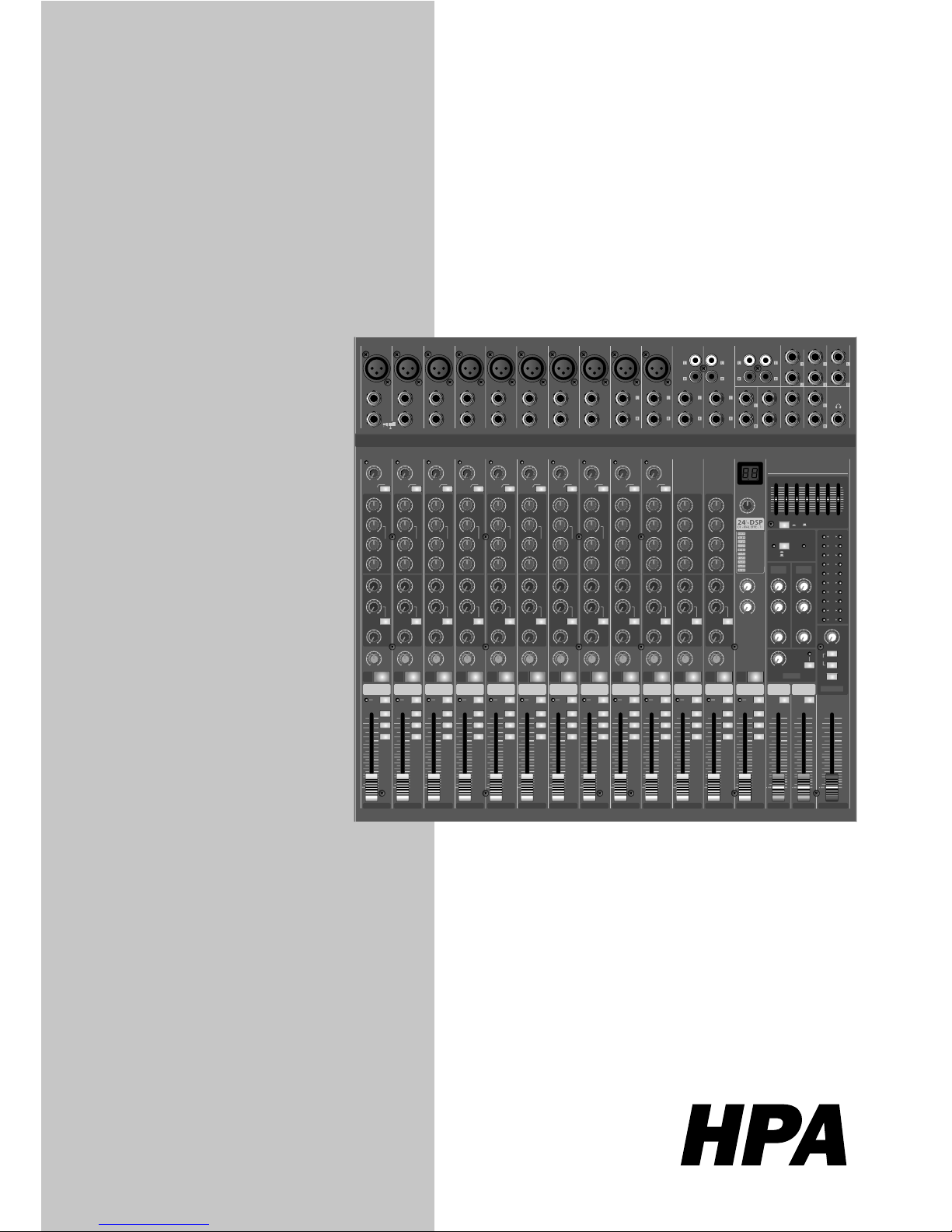
16 CH MIXING CONSOLE
M1636FX
HPA
LINE
INSERT
5
MIC
LINE
INSERT
6
MIC
LINE
INSERT
7
MIC
LINE
INSERT
8
MIC
CHANNEL 1
CH
1
LINE
INSERT
1
MIC
OUT IN
TRIM
PEAK
AUX 2
EFX
L / R
3 / 4
1 / 2
010
5
PRE/POST
PFL
10
5
0
5
10
15
20
30
40
LINE
INSERT
2
MIC
MF
HF
12kHz
LF
80Hz
LINE
INSERT
3
MIC
LINE
INSERT
4
MIC
-30+14
-6 -50
30
-15 +15
0
-15 +15
0
-15 +15
0
FREQ
Hz
100 8k
400
010
5
AUX 1
010
5
PAN
LR
75Hz
MF
-15 +15
0
FREQ
Hz
100 8k
400
MF
-15 +15
0
FREQ
Hz
100 8k
400
MF
-15 +15
0
FREQ
Hz
100 8k
400
MF
-15 +15
0
FREQ
Hz
100 8k
400
MF
-15 +15
0
FREQ
Hz
100 8k
400
MF
-15 +15
0
FREQ
Hz
100 8k
400
MF
-15 +15
0
FREQ
Hz
100 8k
400
CHANNEL 2
CH
2
TRIM
PEAK
AUX 2
EFX
L / R
3 / 4
1 / 2
010
5
PRE/POST
PFL
10
5
0
5
10
15
20
30
40
HF
12kHz
LF
80Hz
-30+14
-6 -50
30
-15 +15
0
-15 +15
0
010
5
AUX 1
010
5
PAN
LR
75Hz
CHANNEL 3
CH
3
TRIM
PEAK
AUX 2
EFX
L / R
3 / 4
1 / 2
010
5
PRE/POST
PFL
10
5
0
5
10
15
20
30
40
HF
12kHz
LF
80Hz
-30+14
-6 -50
30
-15 +15
0
-15 +15
0
010
5
AUX 1
010
5
PAN
LR
75Hz
CHANNEL 4
CH
4
TRIM
PEAK
AUX 2
EFX
L / R
3 / 4
1 / 2
010
5
PRE/POST
PFL
10
5
0
5
10
15
20
30
40
HF
12kHz
LF
80Hz
-30+14
-6 -50
30
-15 +15
0
-15 +15
0
010
5
AUX 1
010
5
PAN
LR
75Hz
CHANNEL 5
CH
5
TRIM
PEAK
AUX 2
EFX
L / R
3 / 4
1 / 2
010
5
PRE/POST
PFL
10
5
0
5
10
15
20
30
40
HF
12kHz
LF
80Hz
-30+14
-6 -50
30
-15 +15
0
-15 +15
0
010
5
AUX 1
010
5
PAN
LR
75Hz
CHANNEL 6
CH
6
TRIM
PEAK
AUX 2
EFX
L / R
3 / 4
1 / 2
010
5
PRE/POST
PFL
10
5
0
5
10
15
20
30
40
HF
12kHz
LF
80Hz
-30+14
-6 -50
30
-15 +15
0
-15 +15
0
010
5
AUX 1
010
5
PAN
LR
75Hz
CHANNEL 7
CH
7
TRIM
PEAK
AUX 2
EFX
L / R
3 / 4
1 / 2
010
5
PRE/POST
PFL
10
5
0
5
10
15
20
30
40
HF
12kHz
LF
80Hz
-30+14
-6 -50
30
-15 +15
0
-15 +15
0
010
5
AUX 1
010
5
PAN
LR
75Hz
CHANNEL 8
CH
8
TRIM
PEAK
AUX 2
EFX
L / R
3 / 4
1 / 2
010
5
PRE/POST
PFL
10
5
0
5
10
15
20
30
40
HF
12kHz
LF
80Hz
-30+14
-6 -50
30
-15 +15
0
-15 +15
0
010
5
AUX 1
010
5
PAN
LR
75Hz
CHANNEL 9/10
CH
9/10
TRIM
PEAK
AUX 2
EFX
L / R
3 / 4
1 / 2
010
5
PRE/POST
PFL
10
5
0
5
10
15
20
30
40
HF
12kHz
LF
80Hz
-20+20
-10 -50
30
-15 +15
0
-15 +15
0
010
5
AUX 1
010
5
BALANCE
LR
75Hz
CHANNEL 11/12
CH
11/12
TRIM
PEAK
AUX 2
EFX
L / R
3 / 4
1 / 2
010
5
PRE/POST
PFL
10
5
0
5
10
15
20
30
40
HF
12kHz
LF
80Hz
-20+20
-10 -50
30
-15 +15
0
-15 +15
0
010
5
AUX 1
010
5
BALANCE
LR
75Hz
CHANNEL 13/14
CH
13/14
AUX 2
EFX
L / R
3 / 4
1 / 2
010
5
PRE/POST
PFL
10
5
0
5
10
15
20
30
40
MID HF
3kHz
HF
12kHz
LF
80Hz
-15 +15
0
-12 +12
0
-12 +12
0
-15 +15
0
MID LF
500Hz
MID HF
3kHz
-12 +12
0
-12 +12
0
MID LF
500Hz
MID HF
3kHz
-12 +12
0
-12 +12
0
MID LF
500Hz
MID HF
3kHz
-12 +12
0
-12 +12
0
MID LF
500Hz
010
5
AUX 1
010
5
BALANCE
LR
CHANNEL 15/16
CH
15/16
AUX 2
EFX
L / R
3 / 4
1 / 2
010
5
PRE/POST
PFL
PFL
10
5
0
5
10
15
20
30
40
HF
12kHz
LF
80Hz
-15 +15
0
-15 +15
0
010
5
AUX 1
010
5
AUX 2
010
5
AUX 1
010
5
BALANCE
LR
EFX RTN GROUP 1/2 GROUP 3/4 MAIN L/R
EFX
L / R
3 / 4
1 / 2
PFL
10
5
0
5
10
15
20
30
40
+10
5
0
5
10
15
20
30
40
+10
5
0
5
10
15
20
30
40
+10
5
0
5
10
15
20
30
40
TO MAIN
L / R
PERFORMANCE
HALL REVERB
PLATE REVERB
SPRING REVERB
ECHO
FLANGE+VERB
CHORUS+VERB
ECHO+VERB
CHORUS
FLANGE
ON
MUTE MUTE MUTE MUTE MUTE MUTE MUTE MUTE MUTE MUTE MUTE MUTE
essional Stereo & GroupPro
f
ompact Mixe
r

WARNING

1
1636FX / M2436FX
nstructions ...................................................................................... 2
Features .............................................................................................. 3
ront Panel ........................................................................................
4
Rear Panel ...................................................................................... 10
oint to Remember ......................................................................... 11
nnections ..................................................................................... 11
Applications ................................................................................... 13
Block Diagram ............................................................................... 15
ecifi cations ................................................................................ 16
rvice ............................................................................................... 18
le of Content
s
Table of Content
s
2
1636FX / M2436FX
ntro
duction
Welcom
e
Thank you for purchasing M 6-Bus SERIES Mixing Console. The M 6-Bus Series provides an
xcellent balance of operability, functionally and ease of use. In order to take full advantage of
the M 6-Bus Series capabilities and en
joy y
ears of trouble - free use, please read this manual
arefully.
npackin
g
Although it is neither complicated to install nor diffi cult to operate your set, a few minutes of your
time is required to read this manual for a properl
y
wired installation and becoming familiar with
its man
y
features and how to use them. Please take a great care in unpacking your set and do
ot discard the carton and other packing materials. They may be needed when moving your set
and are required i
f
it ever becomes necessary to return your set for service. Never place the unit
ear radiators, in front of heating vents, to direct sunlight, in excessive humid or dusty location
to avoid earl
y
damage and for your years of quality entertainment. Connect your complementar
y
omponents as illustrated in the following page
.
MONO
MONO MONO
AUX RETURN
STEREO
RETURN
AUX/EFX
SEND
TAPE IN
CTLR/PHONES
TAPE IN REC OUT
GROUP OUTPUT
FOOT SWITCH
MAIN OUTPUT
CONTROL ROOM
GROUP
1/2
3/4
MAIN
PHANTOM
POWER
PROGRAM
SELECT
LINE 9
LINE 10
9/10
MIC
LINE 11
LINE 12
11/12
LINE 13
LINE 14
LINE 13
LINE 14
LINE 15
LINE 16
13/14
MIC
LINE 15
LINE 16
15/16
TO MAIN
L / R
ON
OFF
ON
OFF
-20
LEVEL
-10
-7
-4
-2
0
+2
+4
+7
63Hz 160Hz 400Hz 1kHz 2.5kHz 6.4kHz 16kHz
CLIP
-12
dB
0
+12
AUX 1 SEND
AUX 2 SEND EFX SEND
HEADPHONE
010
5
LEVEL
010
AUX 1
010
5
EFX
010
5
AUX 2
010
AUX 1
010
5
MAIN
010
5
AUX 2
010
16 CH MIXING CONSOLE
M1636FX
HPA
LINE
INSERT
5
MIC
LINE
INSERT
6
MIC
LINE
INSERT
7
MIC
LINE
INSERT
8
MIC
CHANNEL 1
CH
1
LINE
INSERT
1
MIC
OUT IN
TRIM
PEAK
AUX 2
EFX
L / R
3 / 4
1 / 2
010
5
PRE/POST
PFL
10
5
0
5
10
15
20
30
40
LINE
INSERT
2
MIC
MF
HF
12kHz
LF
80Hz
LINE
INSERT
3
MIC
LINE
INSERT
4
MIC
-30+14
-6 -50
30
-15 +15
0
-15 +15
0
-15 +15
0
FREQ
Hz
100 8k
400
010
5
AUX 1
010
5
PAN
LR
75Hz
MF
-15 +15
0
FREQ
Hz
100 8k
400
MF
-15 +15
0
FREQ
Hz
100 8k
400
MF
-15 +15
0
FREQ
Hz
100 8k
400
MF
-15 +15
0
FREQ
Hz
100 8k
400
MF
-15 +15
0
FREQ
Hz
100 8k
400
MF
-15 +15
0
FREQ
Hz
100 8k
400
MF
-15 +15
0
FREQ
Hz
100 8k
400
CHANNEL 2
CH
2
TRIM
PEAK
AUX 2
EFX
L / R
3 / 4
1 / 2
010
5
PRE/POST
PFL
10
5
0
5
10
15
20
30
40
HF
12kHz
LF
80Hz
-30+14
-6 -50
30
-15 +15
0
-15 +15
0
010
5
AUX 1
010
5
PAN
LR
75Hz
CHANNEL 3
CH
3
TRIM
PEAK
AUX 2
EFX
L / R
3 / 4
1 / 2
010
5
PRE/POST
PFL
10
5
0
5
10
15
20
30
40
HF
12kHz
LF
80Hz
-30+14
-6 -50
30
-15 +15
0
-15 +15
0
010
5
AUX 1
010
5
PAN
LR
75Hz
CHANNEL 4
CH
4
TRIM
PEAK
AUX 2
EFX
L / R
3 / 4
1 / 2
010
5
PRE/POST
PFL
10
5
0
5
10
15
20
30
40
HF
12kHz
LF
80Hz
-30+14
-6 -50
30
-15 +15
0
-15 +15
0
010
5
AUX 1
010
5
PAN
LR
75Hz
CHANNEL 5
CH
5
TRIM
PEAK
AUX 2
EFX
L / R
3 / 4
1 / 2
010
5
PRE/POST
PFL
10
5
0
5
10
15
20
30
40
HF
12kHz
LF
80Hz
-30+14
-6 -50
30
-15 +15
0
-15 +15
0
010
5
AUX 1
010
5
PAN
LR
75Hz
CHANNEL 6
CH
6
TRIM
PEAK
AUX 2
EFX
L / R
3 / 4
1 / 2
010
5
PRE/POST
PFL
10
5
0
5
10
15
20
30
40
HF
12kHz
LF
80Hz
-30+14
-6 -50
30
-15 +15
0
-15 +15
0
010
5
AUX 1
010
5
PAN
LR
75Hz
CHANNEL 7
CH
7
TRIM
PEAK
AUX 2
EFX
L / R
3 / 4
1 / 2
010
5
PRE/POST
PFL
10
5
0
5
10
15
20
30
40
HF
12kHz
LF
80Hz
-30+14
-6 -50
30
-15 +15
0
-15 +15
0
010
5
AUX 1
010
5
PAN
LR
75Hz
CHANNEL 8
CH
8
TRIM
PEAK
AUX 2
EFX
L / R
3 / 4
1 / 2
010
5
PRE/POST
PFL
10
5
0
5
10
15
20
30
40
HF
12kHz
LF
80Hz
-30+14
-6 -50
30
-15 +15
0
-15 +15
0
010
5
AUX 1
010
5
PAN
LR
75Hz
CHANNEL 9/10
CH
9/10
TRIM
PEAK
AUX 2
EFX
L / R
3 / 4
1 / 2
010
5
PRE/POST
PFL
10
5
0
5
10
15
20
30
40
HF
12kHz
LF
80Hz
-20+20
-10 -50
30
-15 +15
0
-15 +15
0
010
5
AUX 1
010
5
BALANCE
LR
75Hz
CHANNEL 11/12
CH
11/12
TRIM
PEAK
AUX 2
EFX
L / R
3 / 4
1 / 2
010
5
PRE/POST
PFL
10
5
0
5
10
15
20
30
40
HF
12kHz
LF
80Hz
-20+20
-10 -50
30
-15 +15
0
-15 +15
0
010
5
AUX 1
010
5
BALANCE
LR
75Hz
CHANNEL 13/14
CH
13/14
AUX 2
EFX
L / R
3 / 4
1 / 2
010
5
PRE/POST
PFL
10
5
0
5
10
15
20
30
40
MID HF
3kHz
HF
12kHz
LF
80Hz
-15 +15
0
-12 +12
0
-12 +12
0
-15 +15
0
MID LF
500Hz
MID HF
3kHz
-12 +12
0
-12 +12
0
MID LF
500Hz
MID HF
3kHz
-12 +12
0
-12 +12
0
MID LF
500Hz
MID HF
3kHz
-12 +12
0
-12 +12
0
MID LF
500Hz
010
5
AUX 1
010
5
BALANCE
LR
CHANNEL 15/16
CH
15/16
AUX 2
EFX
L / R
3 / 4
1 / 2
010
5
PRE/POST
PFL
PFL
10
5
0
5
10
15
20
30
40
HF
12kHz
LF
80Hz
-15 +15
0
-15 +15
0
010
5
AUX 1
010
5
AUX 2
010
5
AUX 1
010
5
BALANCE
LR
EFX RTN GROUP 1/2 GROUP 3/4 MAIN L/R
EFX
L / R
3 / 4
1 / 2
PFL
10
5
0
5
10
15
20
30
40
+10
5
0
5
10
15
20
30
40
+10
5
0
5
10
15
20
30
40
+10
5
0
5
10
15
20
30
40
TO MAIN
L / R
PERFORMANCE
HALL REVERB
PLATE REVERB
SPRING REVERB
ECHO
FLANGE+VERB
CHORUS+VERB
ECHO+VERB
CHORUS
FLANGE
ON
MUTE MUTE MUTE MUTE MUTE MUTE MUTE MUTE MUTE MUTE MUTE MUTE
1636FX/M2436F
X
Professional Stereo & Group Compact Mixe
r
ntr
oductions

3
1636FX / M2436FX
eatures
Feature
s
8 MONO(M1636FX),16 MONO(M2436FX) INPUT AND 4 STEREO INPUT
An
y
sound source of microphones, cassette decks, electronic guitars, organs can be applied to
t
h
e channel input.
MAIN L/R AND GROUP1/2,3/4 OUTPUT
ain L/R and GROUP1/2,3/4 are provided for convenient use.
AUX RETURN AND 2 AUX SEND
For convenient use of external e
quip
ment, AUX SEND and AUX RETURN function are provided.
8 MONO (M1636FX), 16 MONO (M2436FX) CHANNEL INSERT
.
CHANNEL EQUALIZER
The 3 band equalizer are desi
g
ned for ±15dB control on MONO input channels and 4 band
qualizer for stereo input channels-- ±15dB control on HF&LF, ±12dB control on MID HF& MID
.
PFL FUNCTION OF ALL CHs
The PFL function allows
y
ou to monitor any input channels through headphone outputs and con-
trol room outputs be
f
ore the channel fader.
DSP FUNCTION : 100 SELECTABLE PRESETS
A built-in 24bit DSP
(Dig
ital Signal Processor ) with 100 selectable presets including Reverb,
Dela
y
and Chorus, offers dazzling studio quality effects.
FOOT SWITCH
PHANTOM POWER (+48V
)
Phantom power is provided for easy connection of condenser microphones requiring an external
ower supply.
RACK MOUNTIN
G
Detachable rack ears for mounting in a standard 19” rack enclosur
e
EXTERNAL AC POWE
R
4
1636FX / M2436FX
ront Pan
els
CHANNEL 8
L / R
3 / 4
1 / 2
PFL
10
5
0
5
10
15
20
30
40
CHANNEL 11/12
CH
11/12
TRIM
PEAK
AUX 2
EFX
L / R
3 / 4
1 / 2
010
5
PRE/POST
PFL
10
5
0
5
10
15
20
30
40
HF
12kHz
LF
80Hz
-20+20
-10 -50
30
-15 +15
0
-15 +15
0
010
5
AUX 1
010
5
BALANCE
LR
75Hz
CHANNEL 13/14
CH
13/14
AUX 2
EFX
L / R
3 / 4
1 / 2
010
5
PRE/POST
PFL
10
5
0
5
10
15
20
30
40
MID HF
3kHz
HF
12kHz
LF
80Hz
-15 +15
0
-12 +12
0
-12 +12
0
-15 +15
0
MID LF
500Hz
MID HF
3kHz
-12 +12
0
-12 +12
0
MID LF
500Hz
010
5
AUX 1
010
5
BALANCE
LR
MUTE MUTE
MF
-15 +15
0
FREQ
Hz
100 8k
400
CH
8
TRIM
PEAK
AUX 2
EFX
010
5
PRE/POST
HF
12kHz
LF
80Hz
-30+14
-6 -50
30
-15 +15
0
-15 +15
0
010
5
AUX 1
010
5
PAN
LR
75Hz
MUTE
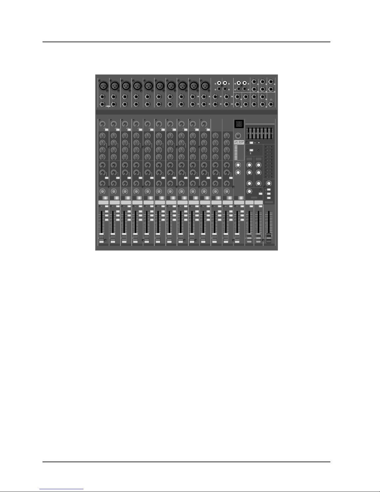
Front Panels Control
s
1). PEAK LED INDICATOR
This LED indicators let
y
ou check the level of the
nal input to the channel. The peak indicator
ligh
ts
when the input si
g
nal reaches 5dB below the channel’s
lipping point. This indicator show the level of the Post-
pre-fader signal. If the PEAK indicator lights more
than briefl
y
on high-level transients, you should use
the TRIM control to decrease the input sensitivit
y of
the
hannel. If this dose not work, reduce the output level
f the connected
source
.
2). TRIM CONTROL
Accordin
g
to the level of the input signal, use this knob
to ad
j
ust the input to an appropriate level. The best
balance o
f S/
N and dynamic range will be achieved if
ou adjust the TRIM control so that the peak indicator
ights occasionally. This control adjusts the channel’s
IC input sensitivity between -50dB and -6dB and the
ine input sensitivity between -30dB and +14dB
.
The mono/stereo combination input channel have a
ensitivity of +20dB to-20dB
3). HPF(High-Pass Filter
)
This switch toggles the HPF on or off. To turn the HPF
n, press the switch In ( ). The HPF cut frequencies
below 7
5Hz
4). EQUALIZER
ONO CHANNEL
This 3-band equalizer ad
j
usts the channel’s high, mid
nd low frequency bands. Setting the knob to the “0”
osition produces a fl at frequency response .Turnin
g
the knob to the right boosts the corresponding frequen-
band ,while turning to the left cuts the band. The
f
ollowing tables shows the EQ type, base frequency ,
nd maximum cut/boost for each of the three bands.
NO MONO STERE
O
STERE
O
COMBINATI
ON
. CHANNEL CONTROL SECTIO
N
STEREO CHANNEL
This 4-band equalizer adjusts the channel’s high,
id and low frequency bands. Setting the knob to
the “0” position produces a fl at frequency re-
ponse .Turning the knob to the right boosts the
orresponding frequency band ,while turning to
the left cuts the band. The following tables shows
the EQ type, base frequency , and maximum
ut/boost for each of the three bands
.
NTROL
ST/CU
T
FREQUEN
CY
TYPE
IG
H
±15d
B
12kHz
helvin
g
±1
5dB
100HZ-8KH
Z
(Variable
)
Peakin
g
LOW ±15d
B0Hz
helvin
g
151515
01
0
01
0
01
0
10
1
1
12
13
NTR
OL
.
T
/CUT
FREQUENC
Y
I
GH±15dB
helvin
g
IGH MID ±12
dB
kHz Peakin
g
LOW MID ±12
dB
00H
Z
Peakin
g
LOW±
15dB
HZ
helvin
g

5
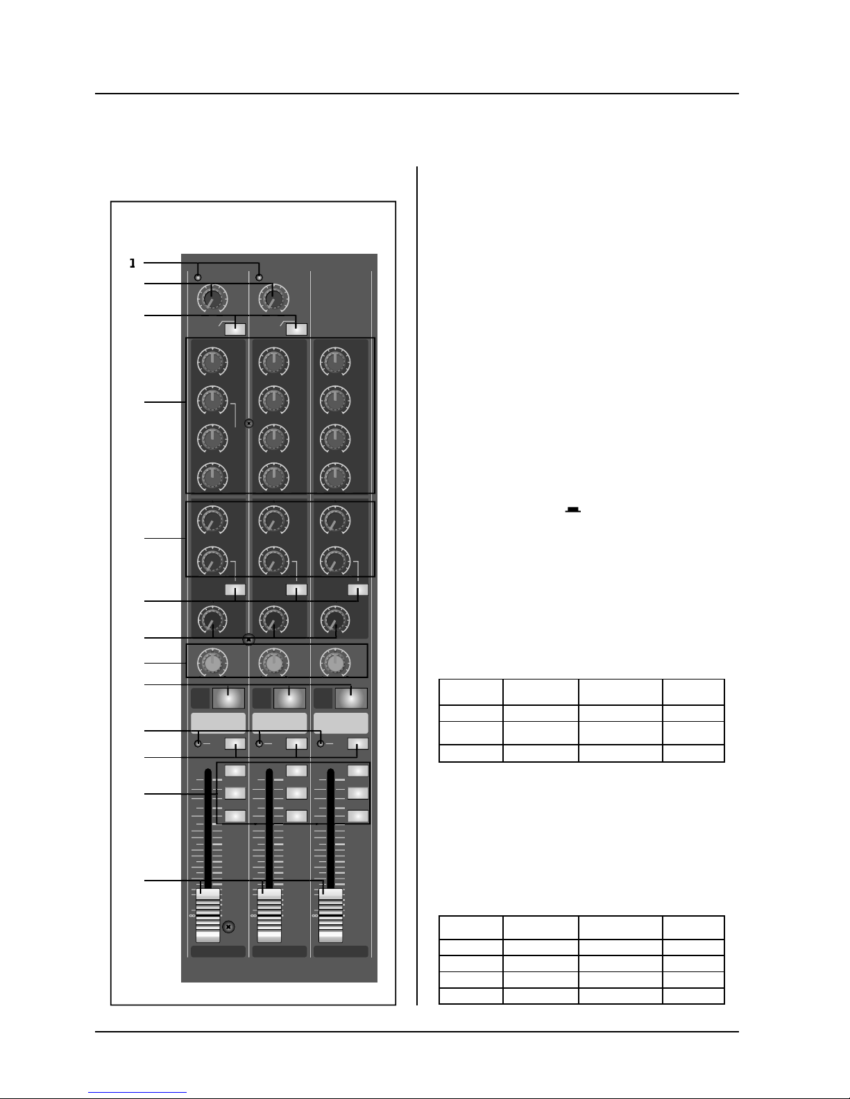
1636FX / M2436FX
ront Panels Control
s
ront Pan
els
his indicator lights when the PFL switch is turned on
.
11). PFL SWITCH
W
hen these switch is depressed, the channel input
ignal can be routed to the PFL bus.
his switch allows you to monitor the pre-fader chanel input signal through headphone outputs and
ontrol room outputs
.
12).ASSIGN SWITCHE
S
se these switches to send the channel’s signal to the
roup1-2 , Group 3-4 and/or MAIN L/R buses. Settin
g
the switch on ( ) causes the signal to be sent to the
orresponding group buses.
13). CHANNEL FADER
his is the channel’s main level control. It determines
the level o
f
the signal that is sent from the channel to
the master mixin
g, g
roup outs and effect buses. It is
the settin
g
s of the input channel faders that determine
the mix, or the balance o
f
sound levels between the
nstruments or other sources connected to the inputs.
W
hen a channel is not being used, its fader should be
et at the minimum position to prevent the addition of
nwanted noise to the main program signal.
5). AUX 1 AND AUX 2 CONTROLS
This AUX1 knob controls the si
g
nal level that the chan-
el sends to the AUX1 bus; the AUX2 knob controls
the si
g
nal level to the AUX2 bus.
I
f y
ou are using stereo channels , the signals from the
L
and
R channels are mixed and send to the AUX1 an
d
AU
X2 buses.
These controls are placed be
f
ore the channel fader ,so
the
y
control the AUX outputs regardless of the settin
g
f the channel f
ade
r.
6). PRE/POST SWITCH
This button determines whether the AUX2 si
g
nal is Pre
or Post
f
ader. Pre means not affected by the position
o
f
the channel fader. Post means is affected by the
osition of the channel fader
.
Note that switch applies to AUX2 only. The signal to
the AUX
1
bus always passes through the channel
f
ade
r fi r
st
7). EFX CONTROL
.
This knobs control the level of the signals sent to EFX
bus. The channel si
g
nals mixed by this bus have their
overall level set b
y
the EFX SEND Control to the EFX
END jack on the front panel. The EFFECT bus signal
is also fed into the internal di
g
ital signal processor
100PRESET DSP).
ince this control is placed after the channel fader,
the si
g
nal level will be affected by the channel fader’s
ettin
g.
8). PAN /BAL CONTROL
AN (Mono Channel
)
s control pans the channel signal across the master
L and R buses, thus determinin
g
the perceived position
o
f
the sound from that channel in the output stereo
ound fi eld. If a PAN control is set all the way to the
left,for exam
p
le, the sound from that channel will be
eard from the left speaker system only.
I
f
it is set all the way to the right, the sound will be
eard from the right speaker system only.
Intermediate settin
g
s will cause the sound to appear at
orresponding locations in the stereo sound fi eld.
BALANCE
(
Stereo Channel
)
This control adjusts the balance or the L/R position of
the stereo input si
g
nal
.
Turning the BALANCE control to the left of center
oves the apparent source toward the
MAIN MIX L
bus, turnin
g
it to the right moves the source toward the
AIN MIX R
bus
.
9). MUTE SWITCH
Set this switch on b
y
pressing it in ( ), you will cut
o
ff
all of its signal feed into the MIAN L/R GROUP1-
2
/
3-4,AUX2(POST),EFX buses. The switch lights up
oran
g
e to indicate that it is on.
10). PFL INDICATOR
6
1636FX / M2436FX
ront Pan
els
STEREO
RETURN
AUX/EFX
SEND
TAPE IN
CTLR/PHONES
GROUP
1/2
3/4
MAIN
PHANTOM
POWER
PROGRAM
SELECT
TO MAIN
L / R
ON
OFF
ON
OFF
-20
LEVEL
-10
-7
-4
-2
0
+2
+4
+7
63Hz 160Hz 400Hz 1kHz 2.5kHz 6.4kHz 16kHz
CLIP
-12
dB
0
+12
010
5
LEVEL
010
AUX 1
010
5
EFX
010
5
AUX 2
010
AUX 1
010
5
MAIN
010
5
AUX 2
010
16 CH MIXING CONSOLE
M1636FX
HPA
PFL
AUX 2
010
5
AUX 1
010
5
EFX RTN GROUP 1/2 GROUP 3/4 MAIN L/R
EFX
L / R
3 / 4
1 / 2
PFL
10
5
0
5
10
15
20
30
40
+10
5
0
5
10
15
20
30
40
+10
5
0
5
10
15
20
30
40
+10
5
0
5
10
15
20
30
40
TO MAIN
L / R
PERFORMANCE
HALL REVERB
PLATE REVERB
SPRING REVERB
ECHO
FLANGE+VERB
CHORUS+VERB
ECHO+VERB
CHORUS
FLANGE
ON
digital effect to the AUX1and AUX2 buses.
4). DSP ON/OFF SWITCH
This switch turns the internal di
g
ital effect on/off.
5). PFL SWITCH
et this switch on if you wish to output the effect signal
t
o
the PFL
bus
.
6). PFL INDICATOR
This indicator li
g
hts when the PFL switch is turned on.
7).ASSIGN SWITCHE
S
et these switches on ( ) to output the internal ef-
f
ect Signal to its corresponding buses (GROUP 1-2 ,
ROUP 3-4 and/or MAIN L/R).
8). EFX RTN Fader
Ad
j
ust the level of the signal sent from the internal
di
g
ital effect to the MAIN and GROUP buses.
9). GROUP FADER (1-2,3-4
)
This fader adjusts the fi nal level to the GROUP
UPUT 1 to 4 JACK
S.
10).TO MAIN SWITCH
this switch is on ( ), the mixer sends the signals
rocessed by the GROUP faders onto the MAIN L/R
bus. The Group 1/3 si
g
nal go to MAIN L and the Group
4 signal go to MAIN R
.
11). MAIN L/R MASTER FADER
S
Adjusts the fi nal signal level to the MAIN L/R OUT
jack
s.
12).RETURN (AUX1, AUX2 AND MAIN L/R CONROLS
)
AUX1 and AUX2 Control
s
Adjust the level of the mixed L/R signal sent from the
ETURN jacks (L (MONO) and R) to the AUX1 and
A
U
X2 B
uses.
MAIN L/R Control
Ad
j
usts the level of the signal sent from the RETURN
j
acks (L (MONO) and R) to the MAIN L/R bus.
13).MASTER SEN
D
AUX1 and AUX2 Control
s
Adjust the level of the signal output to the AUX1 SEND
nd AUX2 SEND jacks
.
Master EFFECT Control
Ad
j
usts the level of the signal on the EFFECT bus.
This is the si
g
nal that is output through the EFFECT
j
ack.
14). TAPE IN PFL INDICATO
R
This indicator lights when the TAPE IN PFL switch is
t
urned on
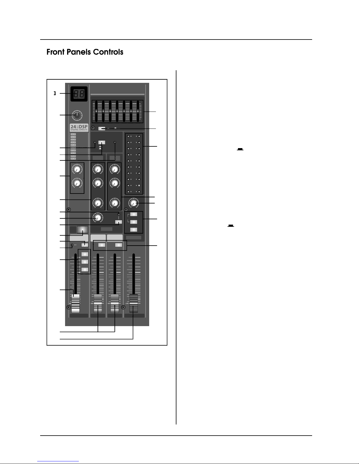
.MAIN CONTROL SECTION
2
1
20
O
O
U
S
23
2
4
12
19
1
8
17
1
6
1
3
15
5
/
1
1
1
0
1). DSP PROGRAM DISPLAY
The Pro
g
ram Number LED displays the number of the
elected effects program.
2). DSP PROGRAM SELECT SWITCH
The pro
g
ram knob selects one of the 100 built-in digital
ects, for each number you select. 24 Bit Digital Ef-
fects processor with hi
g
h quality, studio grade effects
like Dela
y
, Chorus and Reverb.
3). AUX PRE CONTROL
Adj
ust the level of the signal sent from the internal
 Loading...