

Page 1

technical reference guide
hp workstation zx2000
Document Part Number: 5969-3154
April 2003
This manual contains an overview of system specifications, instructions
for removing and replacing system components, information on
configuring your system using the included tools and interfaces, and
detailed troubleshooting information.
Page 2

© 2003 Hewlett-Packard Development Company, L.P.
®
Microsoft
Corporation in the U.S. and other countries.
Intel
under license.
LINUX® is a registered trademark of Linus Torvalds in the U.S. and other countries.
NVIDIA and NVIDIA Quadro are registered trademarks or trademarks of NVIDIA Corporation in the United
States and/or other countries.
All other product names mentioned herein may be trademarks of their respective companies.
Hewlett-Packard Company shall not be liable for technical or editorial errors or omissions contained herein or for
incidental or consequential damages in connection with the furnishing, performance, or use of this material. The
information in this document is provided “as is” without warranty of any kind, including, but not limited to, the
implied warranties of merchantability and fitness for a particular purpose, and is subject to change without notice.
The warranties for HP products are set forth in the express limited warranty statements accompanying such
products. Nothing herein should be construed as constituting an additional warranty.
This document contains proprietary information that is protected by copyright. No part of this document may be
photocopied, reproduced, or translated to another language without the prior written consent of Hewlett-Packard
Company.
WARNING: Text set off in this manner indicates that failure to follow directions could result in bodily
Å
harm or loss of life.
CAUTION: Text set off in this manner indicates that failure to follow directions could result in
Ä
damage to equipment or loss of information.
, Windows®, Windows 2000®, and Windows XP® are registered trademarks of Microsoft
®
and Itanium® are registered trademarks of Intel Corporation in the U.S. and other countries and are used
technical reference guide
hp workstation zx2000
First Edition (April 2003)
Document Part Number: 5969-3154
Page 3

important safety warnings
WARNING: Avoid Electrical Shocks. To avoid electrical shock, do not open the power supplies. There
Å
are no user-serviceable parts inside.
To avoid electrical shock and harm to your eyes by laser light, do not open the DVD laser module. The
laser module should be serviced by service personnel only. Do not attempt to make any adjustment to the
laser unit. Refer to the label on the DVD for power requirements and wavelength. This product is a class I
laser product.
WARNING: Removing and Replacing the Cover. For your safety, never remove the system side cover
Å
without first disconnecting the power cord from the power outlet and removing any connection to a
telecommunications network. If a Power Protection Device is fitted to your system, you must shut down
your computer using its on/off switch, then remove the power cord before removing the system’s side
cover. Remove the Power Protection Device cables before any servicing operation. Always replace the
side cover before switching the system on again.
WARNING: Battery Safety Information. There is a danger of explosion if the battery is incorrectly
Å
installed. For your safety, never attempt to recharge, disassemble, or burn an old battery. Replace the
battery with the same or equivalent type, as recommended by the manufacturer.
The battery in this system is a lithium battery that does not contain any heavy metals. However, to protect
the environment, do not dispose of batteries in household waste. Return used batteries either to the shop
from which you bought them, to the dealer from whom you purchased your system, or to HP so that they
can either be recycled or disposed of in the correct way. Returned batteries will be accepted free of
charge.
WARNING: Avoid Burn Injuries. Some parts inside the computer will be hot. Wait approximately three
Å
to five minutes for them to cool down before touching them.
CAUTION: Avoid Static Electricity. Static electricity can damage electronic components. Turn OFF all
Ä
equipment before installing an accessory card. Don’t let your clothes touch any accessory card. To
equalize the static electricity when replacing an accessory card, rest the accessory card bag on top of the
system unit while you are removing the card from the bag. Handle the card as little as possible and with
care.
CAUTION: Information on Ergonomic Issues. It is strongly recommended that you read the ergonomics
Ä
information, available in the “Working In Comfort” section of this manual, before using your system. You
can access more extensive ergonomics information at: www.hp.com/ergo
NOTE: Recycling Your System. HP has a strong commitment toward the environment. Your HP
system has been designed to respect the environment as much as possible. HP can also take back
your old system for recycling when it reaches the end of its useful life. HP has a product
take-back program in several countries. The collected equipment is sent to an HP recycling
facilities in Europe or the U.S.A. As many parts as possible are reused. The remainder is
recycled. Special care is taken for batteries and other potential toxic substances, these are
reduced into non-harmful components through special chemical processes. If you require more
details about the HP product take-back program, contact your local dealer or your nearest HP
Sales Office.
Page 4

Page 5

Contents
1 Product Information
System features . . . . . . . . . . . . . . . . . . . . . . . . . . . . . . . . . . . . . . . . . . . . . . . . . . . . . . . . . . . . . . . . . 1–1
Physical characteristics . . . . . . . . . . . . . . . . . . . . . . . . . . . . . . . . . . . . . . . . . . . . . . . . . . . . . . . . . . . 1–3
Power specifications. . . . . . . . . . . . . . . . . . . . . . . . . . . . . . . . . . . . . . . . . . . . . . . . . . . . . . . . . . . . . . 1–4
Power consumption and cooling . . . . . . . . . . . . . . . . . . . . . . . . . . . . . . . . . . . . . . . . . . . . . . . . . 1–5
Environmental specifications. . . . . . . . . . . . . . . . . . . . . . . . . . . . . . . . . . . . . . . . . . . . . . . . . . . . . . . 1–5
Front panel . . . . . . . . . . . . . . . . . . . . . . . . . . . . . . . . . . . . . . . . . . . . . . . . . . . . . . . . . . . . . . . . . . . . . 1–6
Rear panel. . . . . . . . . . . . . . . . . . . . . . . . . . . . . . . . . . . . . . . . . . . . . . . . . . . . . . . . . . . . . . . . . . . . . . 1–8
2 Installing or Replacing Parts and Accessories
Overview . . . . . . . . . . . . . . . . . . . . . . . . . . . . . . . . . . . . . . . . . . . . . . . . . . . . . . . . . . . . . . . . . . . . . . 2–1
Internal components. . . . . . . . . . . . . . . . . . . . . . . . . . . . . . . . . . . . . . . . . . . . . . . . . . . . . . . . . . . . . . 2–2
Removal and replacement prerequisites. . . . . . . . . . . . . . . . . . . . . . . . . . . . . . . . . . . . . . . . . . . . . . . 2–4
Read the power and EMI warning and note . . . . . . . . . . . . . . . . . . . . . . . . . . . . . . . . . . . . . . . . 2–4
Gather your tools . . . . . . . . . . . . . . . . . . . . . . . . . . . . . . . . . . . . . . . . . . . . . . . . . . . . . . . . . . . . . 2–4
Follow electrostatic discharge (ESD) precautions. . . . . . . . . . . . . . . . . . . . . . . . . . . . . . . . . . . . 2–4
Removing and replacing covers. . . . . . . . . . . . . . . . . . . . . . . . . . . . . . . . . . . . . . . . . . . . . . . . . . . . . 2–5
Removing the plastic and metal covers . . . . . . . . . . . . . . . . . . . . . . . . . . . . . . . . . . . . . . . . . . . . 2–5
Replacing the covers . . . . . . . . . . . . . . . . . . . . . . . . . . . . . . . . . . . . . . . . . . . . . . . . . . . . . . . . . . 2–8
Removing and replacing the front bezel . . . . . . . . . . . . . . . . . . . . . . . . . . . . . . . . . . . . . . . . . . 2–10
Removing and replacing internal components. . . . . . . . . . . . . . . . . . . . . . . . . . . . . . . . . . . . . . . . . 2–11
Memory modules. . . . . . . . . . . . . . . . . . . . . . . . . . . . . . . . . . . . . . . . . . . . . . . . . . . . . . . . . . . . 2–11
Accessory and graphics cards . . . . . . . . . . . . . . . . . . . . . . . . . . . . . . . . . . . . . . . . . . . . . . . . . . 2–13
Optical drives (CD or DVD) . . . . . . . . . . . . . . . . . . . . . . . . . . . . . . . . . . . . . . . . . . . . . . . . . . . 2–17
Hard drives . . . . . . . . . . . . . . . . . . . . . . . . . . . . . . . . . . . . . . . . . . . . . . . . . . . . . . . . . . . . . . . . 2–20
Power supply . . . . . . . . . . . . . . . . . . . . . . . . . . . . . . . . . . . . . . . . . . . . . . . . . . . . . . . . . . . . . . . 2–23
System fans . . . . . . . . . . . . . . . . . . . . . . . . . . . . . . . . . . . . . . . . . . . . . . . . . . . . . . . . . . . . . . . . 2–24
Airflow guide. . . . . . . . . . . . . . . . . . . . . . . . . . . . . . . . . . . . . . . . . . . . . . . . . . . . . . . . . . . . . . . 2–26
LED status panel . . . . . . . . . . . . . . . . . . . . . . . . . . . . . . . . . . . . . . . . . . . . . . . . . . . . . . . . . . . . 2–27
Processor assembly and power module. . . . . . . . . . . . . . . . . . . . . . . . . . . . . . . . . . . . . . . . . . . 2–28
System board . . . . . . . . . . . . . . . . . . . . . . . . . . . . . . . . . . . . . . . . . . . . . . . . . . . . . . . . . . . . . . . 2–33
System battery . . . . . . . . . . . . . . . . . . . . . . . . . . . . . . . . . . . . . . . . . . . . . . . . . . . . . . . . . . . . . . 2–36
3 System Configuration
Extensible Firmware Interface (EFI) . . . . . . . . . . . . . . . . . . . . . . . . . . . . . . . . . . . . . . . . . . . . . . . . . 3–1
Accessing and navigating the EFI shell. . . . . . . . . . . . . . . . . . . . . . . . . . . . . . . . . . . . . . . . . . . . 3–2
Using the Boot Option Maintenance menu . . . . . . . . . . . . . . . . . . . . . . . . . . . . . . . . . . . . . . . . 3–11
Using the Security/Password menu . . . . . . . . . . . . . . . . . . . . . . . . . . . . . . . . . . . . . . . . . . . . . . 3–21
Baseboard Management Controller (BMC). . . . . . . . . . . . . . . . . . . . . . . . . . . . . . . . . . . . . . . . . . . 3–23
Using the BMC command line interface (CLI). . . . . . . . . . . . . . . . . . . . . . . . . . . . . . . . . . . . . 3–23
technical reference guide v
Page 6

Contents
3 System Configuration
Extensible Firmware Interface (EFI) . . . . . . . . . . . . . . . . . . . . . . . . . . . . . . . . . . . . . . . . . . . . . . . . . 3–1
Accessing and navigating the EFI shell. . . . . . . . . . . . . . . . . . . . . . . . . . . . . . . . . . . . . . . . . . . . 3–2
Using the Boot Option Maintenance menu . . . . . . . . . . . . . . . . . . . . . . . . . . . . . . . . . . . . . . . . 3–11
Using the Security/Password menu . . . . . . . . . . . . . . . . . . . . . . . . . . . . . . . . . . . . . . . . . . . . . . 3–21
Baseboard Management Controller (BMC). . . . . . . . . . . . . . . . . . . . . . . . . . . . . . . . . . . . . . . . . . . 3–23
Using the BMC command line interface (CLI). . . . . . . . . . . . . . . . . . . . . . . . . . . . . . . . . . . . . 3–23
BMC commands . . . . . . . . . . . . . . . . . . . . . . . . . . . . . . . . . . . . . . . . . . . . . . . . . . . . . . . . . . . . 3–24
IPMI commands . . . . . . . . . . . . . . . . . . . . . . . . . . . . . . . . . . . . . . . . . . . . . . . . . . . . . . . . . . . . 3–26
Firmware upgrades. . . . . . . . . . . . . . . . . . . . . . . . . . . . . . . . . . . . . . . . . . . . . . . . . . . . . . . . . . . . . . 3–31
4 Troubleshooting
Troubleshooting overview . . . . . . . . . . . . . . . . . . . . . . . . . . . . . . . . . . . . . . . . . . . . . . . . . . . . . . . . . 4–1
Identifying and diagnosing hardware problems. . . . . . . . . . . . . . . . . . . . . . . . . . . . . . . . . . . . . . . . . 4–2
System e-buzzer. . . . . . . . . . . . . . . . . . . . . . . . . . . . . . . . . . . . . . . . . . . . . . . . . . . . . . . . . . . . . . 4–3
LEDs . . . . . . . . . . . . . . . . . . . . . . . . . . . . . . . . . . . . . . . . . . . . . . . . . . . . . . . . . . . . . . . . . . . . . . 4–5
Monitor troubleshooting . . . . . . . . . . . . . . . . . . . . . . . . . . . . . . . . . . . . . . . . . . . . . . . . . . . . . . 4–14
Running Diagnostic Software Tools . . . . . . . . . . . . . . . . . . . . . . . . . . . . . . . . . . . . . . . . . . . . . . . . 4–15
HP e-DiagTools hardware diagnostics . . . . . . . . . . . . . . . . . . . . . . . . . . . . . . . . . . . . . . . . . . . 4–15
Additional diagnostics tools for HP-UX . . . . . . . . . . . . . . . . . . . . . . . . . . . . . . . . . . . . . . . . . . 4–18
A System Accessories
Graphics cards . . . . . . . . . . . . . . . . . . . . . . . . . . . . . . . . . . . . . . . . . . . . . . . . . . . . . . . . . . . . . . . . . A–1
Supported graphics cards. . . . . . . . . . . . . . . . . . . . . . . . . . . . . . . . . . . . . . . . . . . . . . . . . . . . . . A–1
Selecting a monitor . . . . . . . . . . . . . . . . . . . . . . . . . . . . . . . . . . . . . . . . . . . . . . . . . . . . . . . . . . A–2
Mass storage devices . . . . . . . . . . . . . . . . . . . . . . . . . . . . . . . . . . . . . . . . . . . . . . . . . . . . . . . . . . . . A–6
Hard disk drives. . . . . . . . . . . . . . . . . . . . . . . . . . . . . . . . . . . . . . . . . . . . . . . . . . . . . . . . . . . . . A–6
CD-RW drive. . . . . . . . . . . . . . . . . . . . . . . . . . . . . . . . . . . . . . . . . . . . . . . . . . . . . . . . . . . . . . . A–7
DVD-ROM drive. . . . . . . . . . . . . . . . . . . . . . . . . . . . . . . . . . . . . . . . . . . . . . . . . . . . . . . . . . . . A–8
B System Board
System board overview . . . . . . . . . . . . . . . . . . . . . . . . . . . . . . . . . . . . . . . . . . . . . . . . . . . . . . . . . . B–1
System board components . . . . . . . . . . . . . . . . . . . . . . . . . . . . . . . . . . . . . . . . . . . . . . . . . . . . . . . . B–3
Intel® Itanium® 2 processor. . . . . . . . . . . . . . . . . . . . . . . . . . . . . . . . . . . . . . . . . . . . . . . . . . . B–3
Processor bus . . . . . . . . . . . . . . . . . . . . . . . . . . . . . . . . . . . . . . . . . . . . . . . . . . . . . . . . . . . . . . . B–3
ZX1 I/O and memory controller . . . . . . . . . . . . . . . . . . . . . . . . . . . . . . . . . . . . . . . . . . . . . . . . B–4
I/O bus interface . . . . . . . . . . . . . . . . . . . . . . . . . . . . . . . . . . . . . . . . . . . . . . . . . . . . . . . . . . . . B–4
Processor dependent hardware controller . . . . . . . . . . . . . . . . . . . . . . . . . . . . . . . . . . . . . . . . . B–5
Dual serial controller . . . . . . . . . . . . . . . . . . . . . . . . . . . . . . . . . . . . . . . . . . . . . . . . . . . . . . . . . B–5
Field programmable gate array controller . . . . . . . . . . . . . . . . . . . . . . . . . . . . . . . . . . . . . . . . . B–6
Baseboard management controller (BMC) . . . . . . . . . . . . . . . . . . . . . . . . . . . . . . . . . . . . . . . . B–6
IDE interface . . . . . . . . . . . . . . . . . . . . . . . . . . . . . . . . . . . . . . . . . . . . . . . . . . . . . . . . . . . . . . . B–6
10/100/1000 BT LAN . . . . . . . . . . . . . . . . . . . . . . . . . . . . . . . . . . . . . . . . . . . . . . . . . . . . . . . . B–7
vi technical reference guide
Page 7

C Part Numbers
Exploded view . . . . . . . . . . . . . . . . . . . . . . . . . . . . . . . . . . . . . . . . . . . . . . . . . . . . . . . . . . . . . . . . . C–1
D Event, Error and Warning Messages
EFI error and warning messages . . . . . . . . . . . . . . . . . . . . . . . . . . . . . . . . . . . . . . . . . . . . . . . . . . . D–1
SEL and FPL log entries . . . . . . . . . . . . . . . . . . . . . . . . . . . . . . . . . . . . . . . . . . . . . . . . . . . . . . . . . D–4
Accessing the logs with BMC CLI commands . . . . . . . . . . . . . . . . . . . . . . . . . . . . . . . . . . . . . D–4
System specific events. . . . . . . . . . . . . . . . . . . . . . . . . . . . . . . . . . . . . . . . . . . . . . . . . . . . . . . . D–5
Events without sensors . . . . . . . . . . . . . . . . . . . . . . . . . . . . . . . . . . . . . . . . . . . . . . . . . . . . . . . D–8
Index
Contents
technical reference guide vii
Page 8

Contents
viii technical reference guide
Page 9

This chapter provides an overview of the hp workstation zx2000, including:
■
System features
■
Physical characteristics
■
Power specifications
■
Environmental specifications
■
Front panel features
■
Rear panel connectors
system features
Feature Description
Processor Intel® Itanium® 2
1
product information
•900 MHz
• 1.5 MB cache on chip
Firmware 8 MB flash EEPROM
• Configured using Extensible Firmware Interface (EFI)
Operating system Models include one of the following:
•HP-UX
•Linux®
• Microsoft® Windows® XP 64-Bit Edition Version 2003
Main memory Capacity:
• 512 MB min. (2 x 256 MB)
• 8 GB max. (4 x 2 GB)
Type: PC2100 ECC registered DDR266 SDRAM
Sockets: Four DIMM sockets
Bus Bandwidth: 4.25 GB/sec
For memory loading order and detailed memory installation
instructions, see “Loading Order” on page 2-12.
Hard drive(s) Models include one or two of the following:
• Ultra ATA-100 IDE: 40 GB, 80 GB or 120 GB
• Ultra 160 SCSI: 36 GB, 73 GB or 146 GB
technical reference guide 1–1
Page 10

Product Information
Feature Description
Optical drive(s) Models include one of the following IDE drives:
• 48X CD-RW
•16X DVD-ROM
SCSI controller
(optional)
IDE controller Ultra ATA-100 capable controller supporting a total of two IDE buses
Graphics controllers Models available with a range of AGP graphics cards (Appendix A).
Accessory card sockets Six sockets total:
I/O connectors • 10/100/1000 LAN connector
Models may include one Ultra 160 SCSI adapter
and four IDE devices:
•Two internal hard drives
• Two front-access optical drives
• One AGP Pro 50 1.5V-only 4
• Three full-length and one half-length 3.3V 64-bit 66 MHz PCI-X
sockets
• One full-length 3.3V 64-bit 133 MHz PCI-X socket.
• Four USB 2.0 480 Mb/s connectors:
•Two front-access
•Two rear-access
•Two 9-pin serial ports:
•UART 16550 buffered
• RS-232-C
32-bit socket
×
Input devices USB keyboard and mouse:
• HP 104/105 key keyboard, available in 13 localized layouts
• HP three-button mouse, standard or scroll-wheel
IEEE-1394 FireWire
(optional)
Audio Integrated audio features:
1–2 technical reference guide
Models may include IEEE-1394 interface cards:
• IEEE-1394A, OHCI
• Three ports (two rear, one internal)
• 16-bit stereo
• Internal CD audio connector
• Full duplex
• Three rear-connect audio jacks:
•Microphone
•Line in
•Line out
Page 11

physical characteristics
Characteristic hp workstation zx2000
Product Information
Weight
1
Tower system Minimum: 21.98 kg (48.45 lb.)
Maximum: 24.80 kg (54.68 lb.)
Rack system Minimum: 17.77 kg (39.18 lb.)
Maximum: 20.60 kg (45.41 lb.)
Dimensions
Tower system Height: 502.6 mm (19.79 in.)
Depth: 512.4 mm (20.17 in.)
Width: 268.0 mm (10.55 in.)
Rack system Height: 175.3 mm (6.90 in.)
Depth: 510.9 mm (20.11 in.)
Width: 482.5 mm (18.99 in.)
Footprint, tower system
Space requirement, rack system
1. Excludes keyboard, mouse and display.
0.09 m2 (0.98 sq. ft.)
4 units
technical reference guide 1–3
Page 12

Product Information
power specifications
Available power (output) is the maximum DC power that the power supply can supply to the
system.
Maximum input power is what the power supply requires from the AC line to deliver that
maximum DC output (given worst case efficiency and max loading).
Maximum input current is the worst case/highest current given the lowest input voltage and the
maximum input power.
Parameter Total Rating PCI Sockets AGP Sockets
Input voltage (wide-range) 100-127VAC
200-240VAC
Max input current 6.4A at 100VAC
3.2A at 200VAC
Input frequency 50 – 60 Hz
Max input power required 643W
Max available output power 450W
Max current at +12V 14A
Max current at +12V-CPU 16A
Max current at +3.3V 34A
Max current at +5V 20A
Max current at –12V 0.55A
Max current at +5Vsb 2A
5 sockets
available at
15W/socket
Total of 75W
1 socket
available at
50W/socket
The power supply has Active Power Factor Correction (APFC) that meets EN61000-3-2 over the
range of 88-255 VAC rms.
1–4 technical reference guide
Page 13

power consumption and cooling
The power consumptions listed in the following table are valid for a standard configuration as
shipped (4 GB of memory, 450W power supply, two hard disk drives, and one graphics card).
All information in this section is based on primary power consumptions.
Additional Component
Processor 130W 443.6 Btu/h
IDE hard disk drive with I/O access 23W 78.4 Btu/h
IDE hard disk without I/O access (idle) 16W 54.5 Btu/h
PCI card 10W to 25W 34.12 Btu/h to 85.30 Btu/h
AGP card 50W (maximum) 170.6 Btu/h
environmental specifications
Environmental Specifications (System Processing Unit with Hard Disk)
Product Information
Operating temperature +5° C to +35° C (+41° F to +95° F)
Storage temperature -40° C to +70 C (-40° F to +158° F)
Over-temperature shutdown +40° C (+104° F)
Operating humidity 15% to 85% relative (non-condensing)
Storage humidity 8% to 85% relative (non-condensing)
Operating altitude 0-3000 m (0-10,000 ft.)
Storage altitude (long-term) 0-4600 m (0-15,000 ft.)
Operating temperature and humidity ranges may vary depending on the installed mass storage
devices. High humidity levels can cause improper disk operation. Low humidity levels can
aggravate static electricity problems and cause excessive wear of the disk surface.
technical reference guide 1–5
Page 14

Product Information
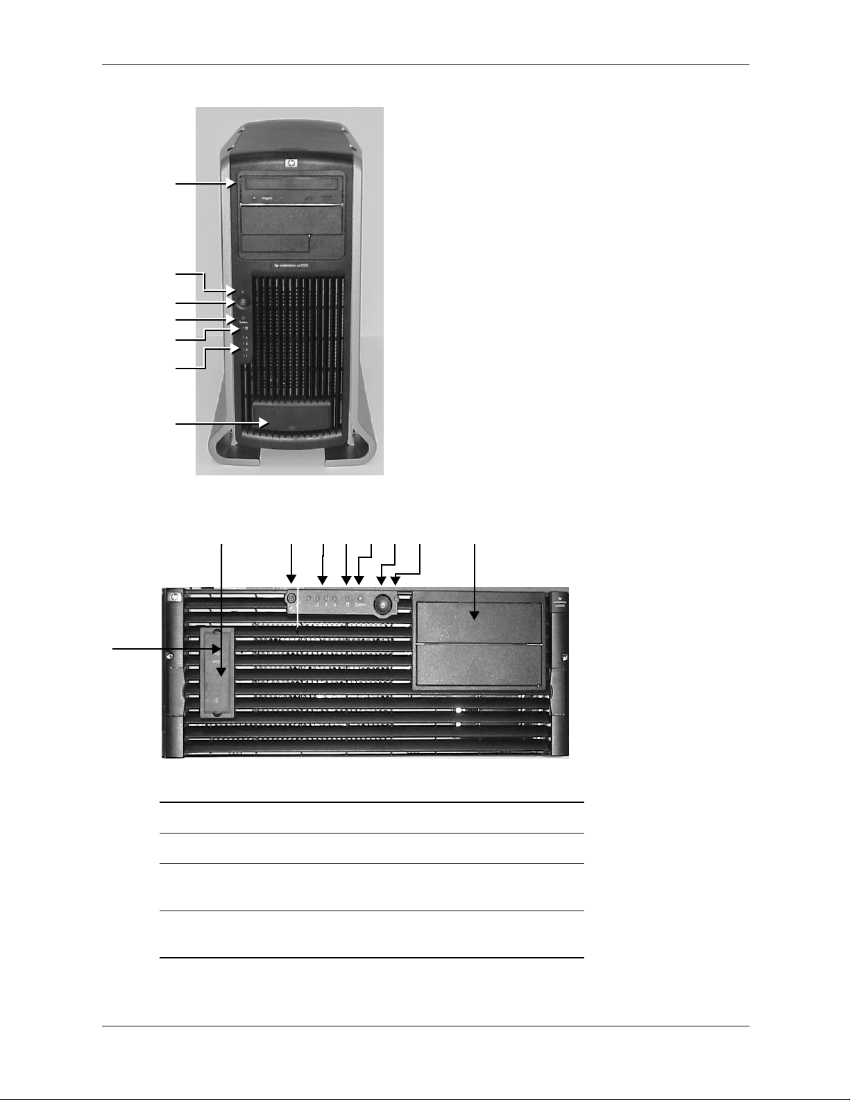
front panel
The hp workstation zx2000 front panel has the following features:
■
Two front-access USB connectors.
■
Two front-access optical drive bays.
Power Button turns the system power on or off.
■
Power LED is green when the power is on or the power button is pushed in. If the power is
■
on and the button is pushed in, the light will stay on even after the system is powered down.
When the button is released, the green light turns off.
Activity LED indicates whether the system is accessing any of the hard drives or optical
■
drives (IDE or SCSI). If the LED is:
off, the system is off, or the system is not accessing internal drives
❏
blinking green, the system is accessing an internal drive
❏
NOTE: The Activity LED automatically communicates with IDE hard drives or optical drives.
To communicate with SCSI drives, a SCSI LED activity cable must connect the SCSI card and
the system board. The Activity LED is active only on systems purchased after March 2003.
System and Diagnostic LEDs provide information about system errors.
■
Locator Button and LED (rack-mount configuration only) identifies the rack position of
■
the workstation.
1–6 technical reference guide
Page 15
Product Information
1
2
3
4
5
6
7
Front Panel, Tower Configuration
12345687
Front Panel, Rack Configuration
1 Optical drive bays 5 Activity LED
2 Power LED 6 Diagnostic LEDs 1-4
3 Power button 7 Front-access USB connectors
(behind door)
4 System LED 8 Locator LED and button
(rack-mounted system only)
technical reference guide 1–7
Page 16
Product Information
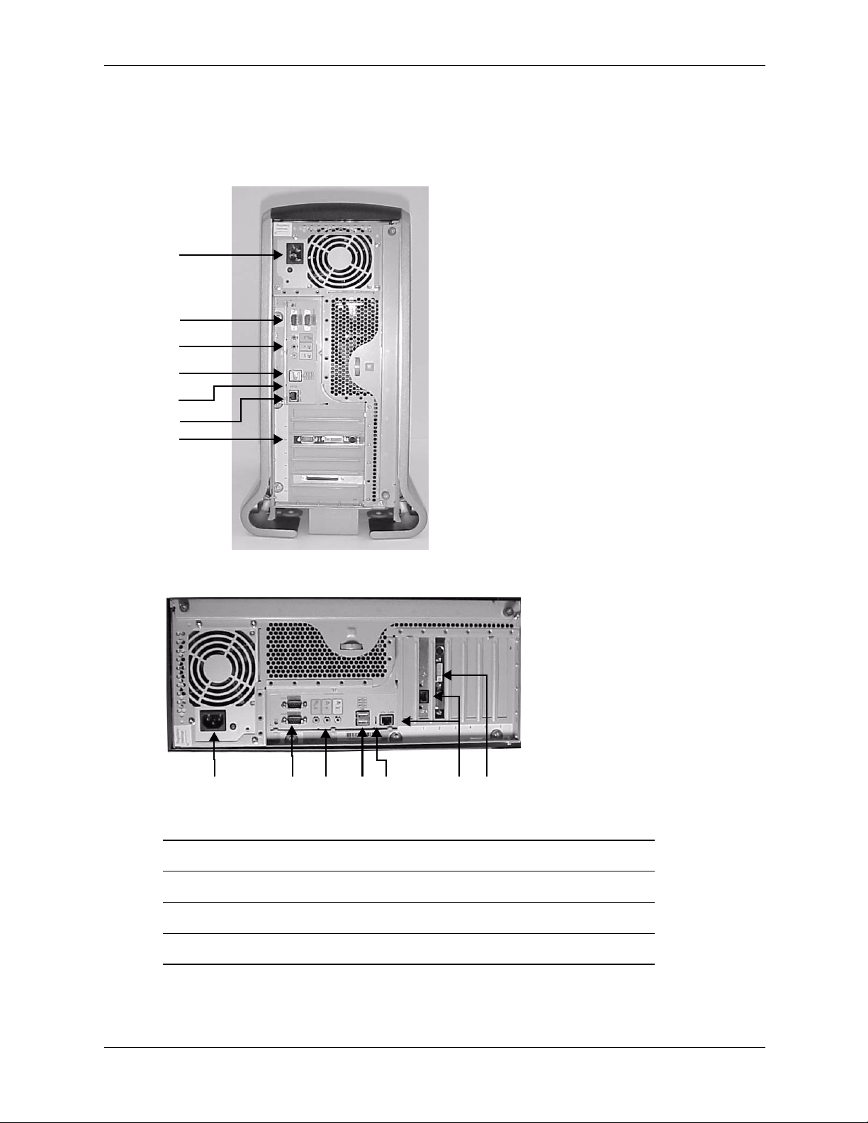
rear panel
The connectors are shaped to go in one way only. Refer to the label on the back of the
workstation.
1
2
3
4
5
6
7
Rear Panel Connectors, Tower Configuration
124
Rear Panel Connectors, Rack-mounted Configuration
1 Power 5 LAN LEDs
2 Serial ports 6 Built-in LAN and optional 2nd LAN ports
3 Audio
4 USB
(headphone, microphone)
37
5
7 Monitor port(s) on graphics card
6
1–8 technical reference guide
Page 17

installing or replacing parts and accessories
overview
This chapter contains the following sections:
■
“Internal components” on page 2-2 shows photos of the internal components and system
board. These will help you locate components.
■
“Removal and replacement prerequisites” on page 2-4 provides information you must know
before you remove components.
■
“Removing and replacing covers” on page 2-5 and “Removing and replacing the front bezel”
on page 2-10 explain two tasks you perform for many remove/replace procedures.
■
The remaining sections explain how to remove and replace components:
❏
Memory modules, page 2-11
❏
Accessory and graphics cards, page 2-13
❏
Optical drives (CD or DVD), page 2-17
2
❏
Hard drives, page 2-20
❏
Power supply, page 2-23
❏
System fans, page 2-24
❏
Airflow guide, page 2-26
❏
LED status panel, page 2-27
❏
Processor assembly and power module, page 2-28
❏
System board, page 2-33
❏
System battery, page 2-36
technical reference guide 2–1
Page 18
Installing or Replacing Parts and Accessories
6
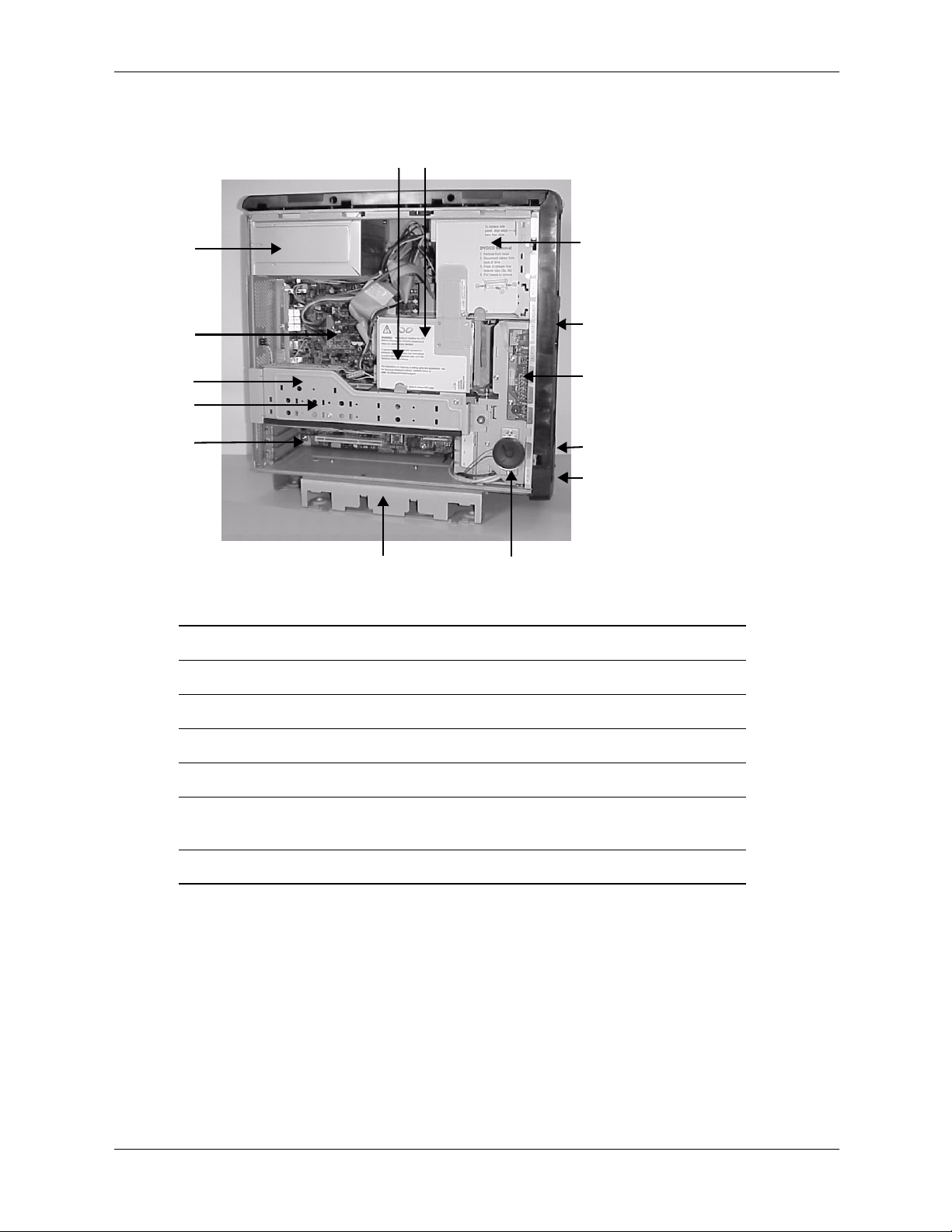
internal components
7
5
4
3
2
1
14
zx2000 Main Components
1 PCI sockets 8 Optical drive(s)
2 AGP video card (behind arm) 9 System fans (behind front bezel)
13
8
9
10
11
12
3 AGP retainer arm 10 LED status panel
4 Memory DIMMs 11 Serial number label (behind door)
5 Power supply 12 Front-access USB ports (behind door)
6 Processor/fan assembly
(behind hard-drive cage)
7 Hard-drive cage 14 Pedestal (tower system)
2–2 technical reference guide
13 Internal speaker
Page 19
Installing or Replacing Parts and Accessories
543
6
7
2
8
1
11
10
9
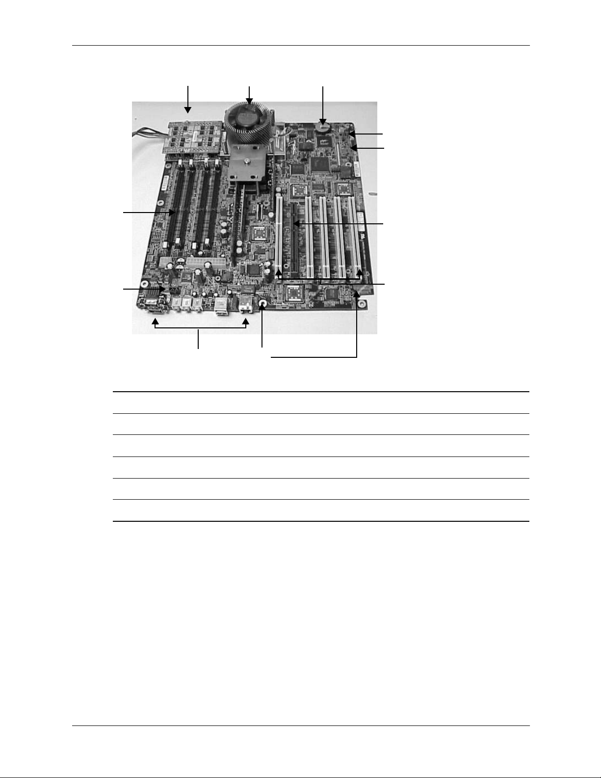
zx2000 System Board
1 CD Audio connector 7 Internal speaker connector
2 Memory DIMM sockets (4) 8 AGP-Pro 50 socket
3 CPU Power Module 9 PCI sockets (5)
4 CPU Assembly 10 SCSI LED activity connectors
5 Battery 11 Rear panel connectors
6 USB front cable connector
For additional information on the system board, see Appendix B.
technical reference guide 2–3
Page 20

Installing or Replacing Parts and Accessories
removal and replacement prerequisites
Before you remove or replace parts, you must:
■
Read the power and EMI warning and note below. (Your safety is important!)
■
Gather your tools.
■
Follow electrostatic discharge (ESD) precautions.
read the power and EMI warning and note
WARNING: For the installation and removal procedures in this chapter, you must:
Å
gather your tools
power off the workstation, and
■
unplug the workstation power cord from the AC power outlet.
■
NOTE: To maintain FCC Electromagnetic Interference (EMI) compliance, verify that all covers
are replaced and that all screws are properly seated.
You ne e d:
■
Flat blade screwdriver
■
T-15 Torx driver
■
Special processor tool (provided with replacement CPU)
■
Static-free mat
■
Static strap
follow electrostatic discharge (ESD) precautions
To prevent damage to this system, observe all of the following ESD precautions while
performing the system parts removal/replacement procedures:
■
Work on a static-free mat.
■
Wear a static strap to ensure that any accumulated electrostatic charge is discharged from
your body to ground.
■
Create a common ground for the equipment you are working on by connecting the static-free
mat, static strap and peripheral units to that piece of equipment.
■
Keep uninstalled printed circuit boards in their protective antistatic bags.
■
Handle printed circuit boards by their edges, once you have removed them from their
protective antistatic bags.
2–4 technical reference guide
Page 21
removing and replacing covers
To upgrade, remove or replace system components, you must first remove the covers from the
system chassis. This section explains how to remove and replace the covers for both tower and
rackmount configurations.
WARNING: Never remove the system cover(s) without first turning the system off and unplugging the
Å
power cord from the outlet or Power Protection Device. Always replace the cover(s) before turning the
workstation on.
removing the plastic and metal covers
1. Turn off the system and disconnect the power cable and all other cables from the back of the
system.
2. Access the metal cover.
Rackmount system: Release the glide-rail retainers and slide the system outward as far as you
can so that you have access to the system cover.
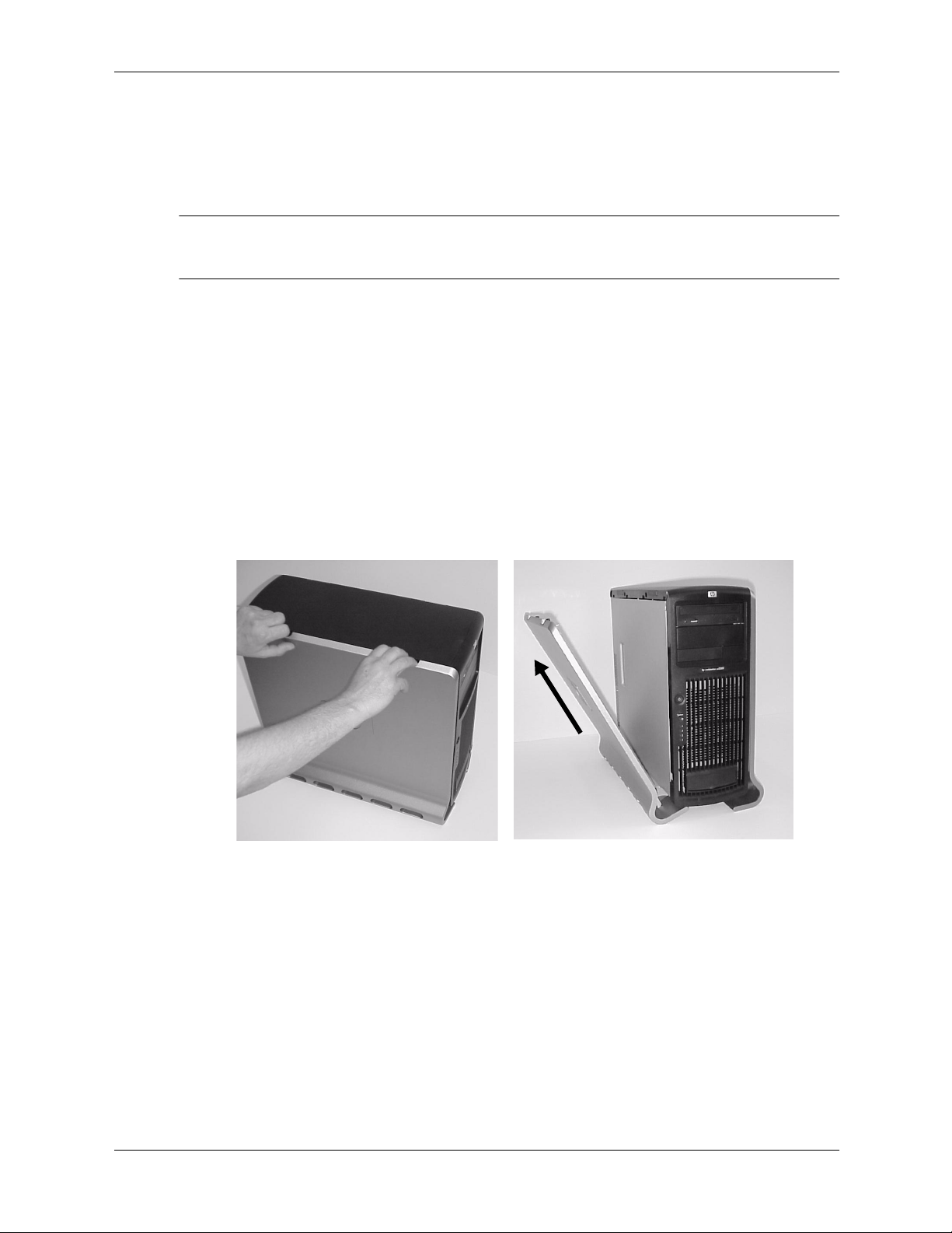
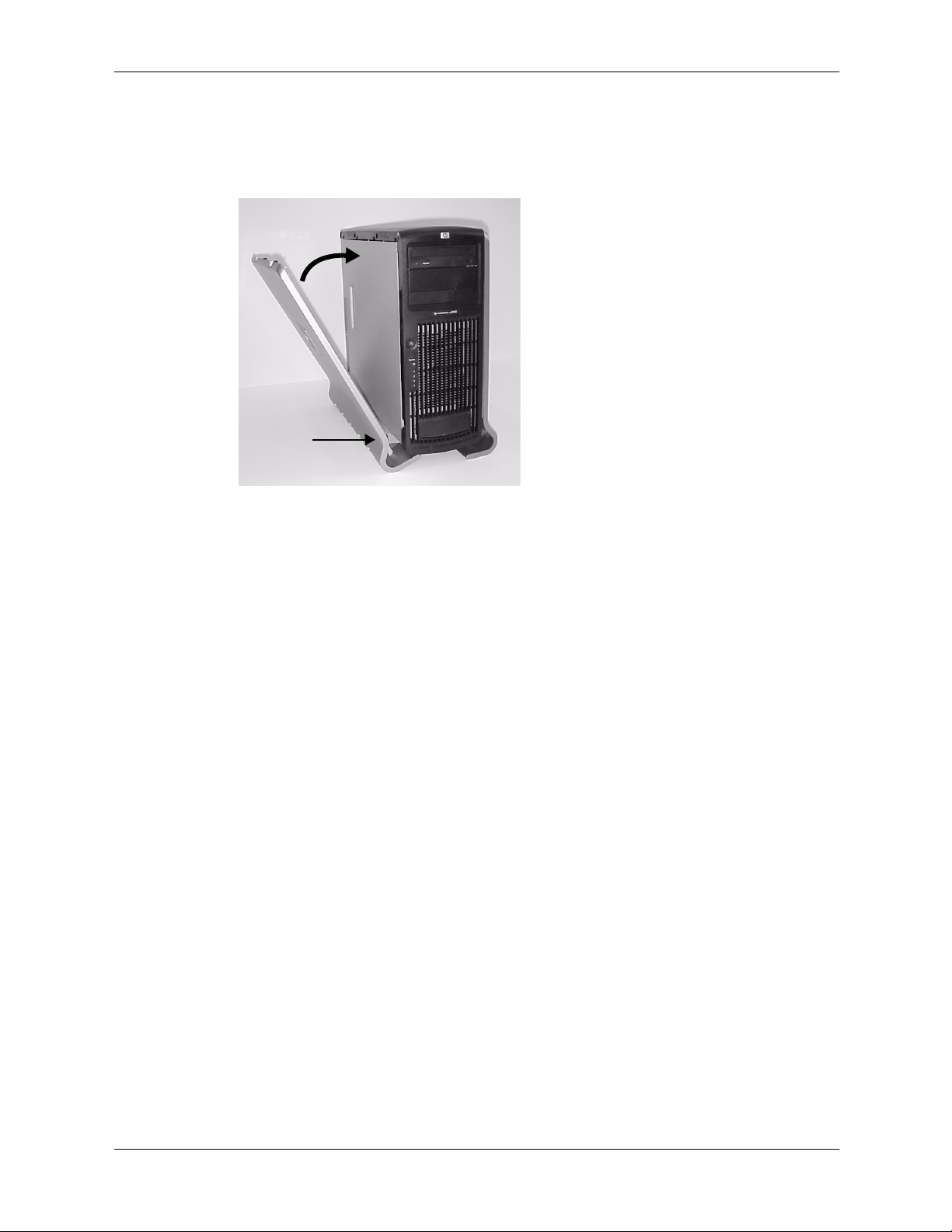
Tower system: remove the plastic cover. With the front panel of the tower case facing right:
a. Grasp both indentations at the top of the side panel and pull outward.
Installing or Replacing Parts and Accessories
b. Lift the plastic cover off of the system chassis.
Removing the Plastic Cover (Tower System Only)
technical reference guide 2–5
Page 22
Installing or Replacing Parts and Accessories
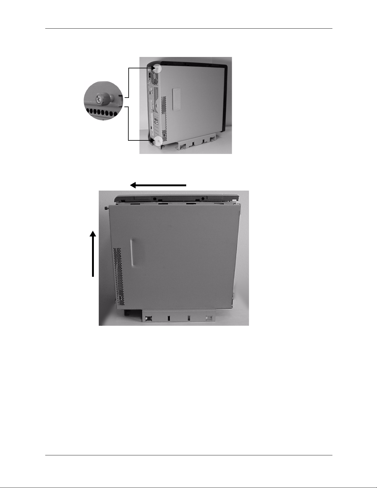
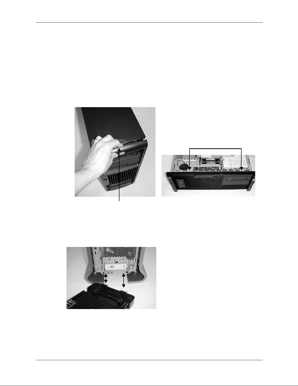
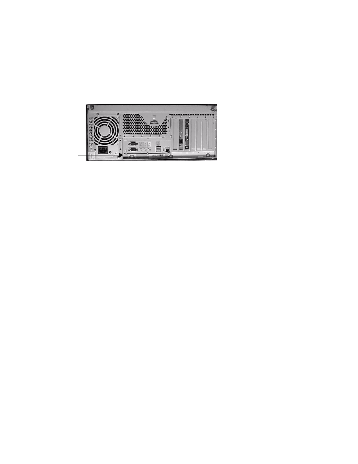
3. Loosen the two blue screws on the cover near the back panel of the chassis.
Unscrewing the Metal Side Cover
4. Slide the cover about 60 mm (1.5 in.) toward the back of the chassis, then lift it off.
A
B
Removing the Metal Side Cover
2–6 technical reference guide
Page 23
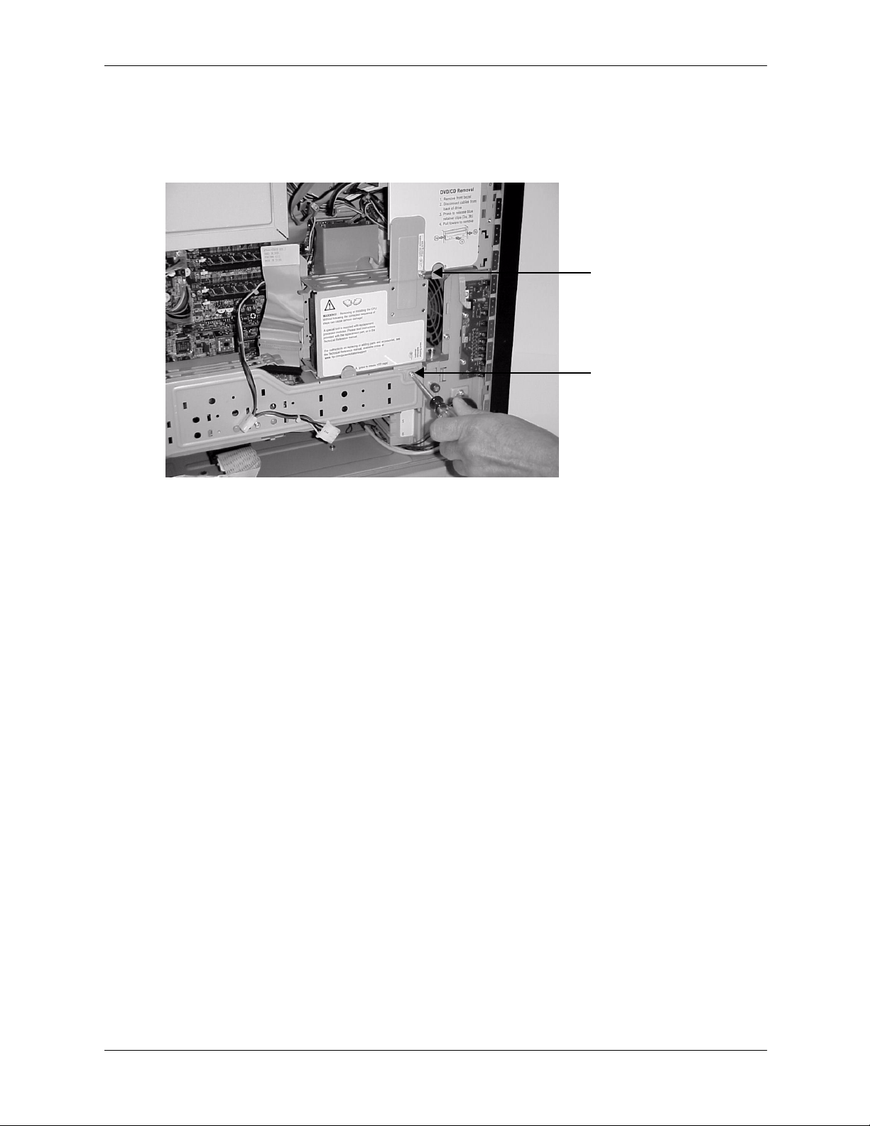
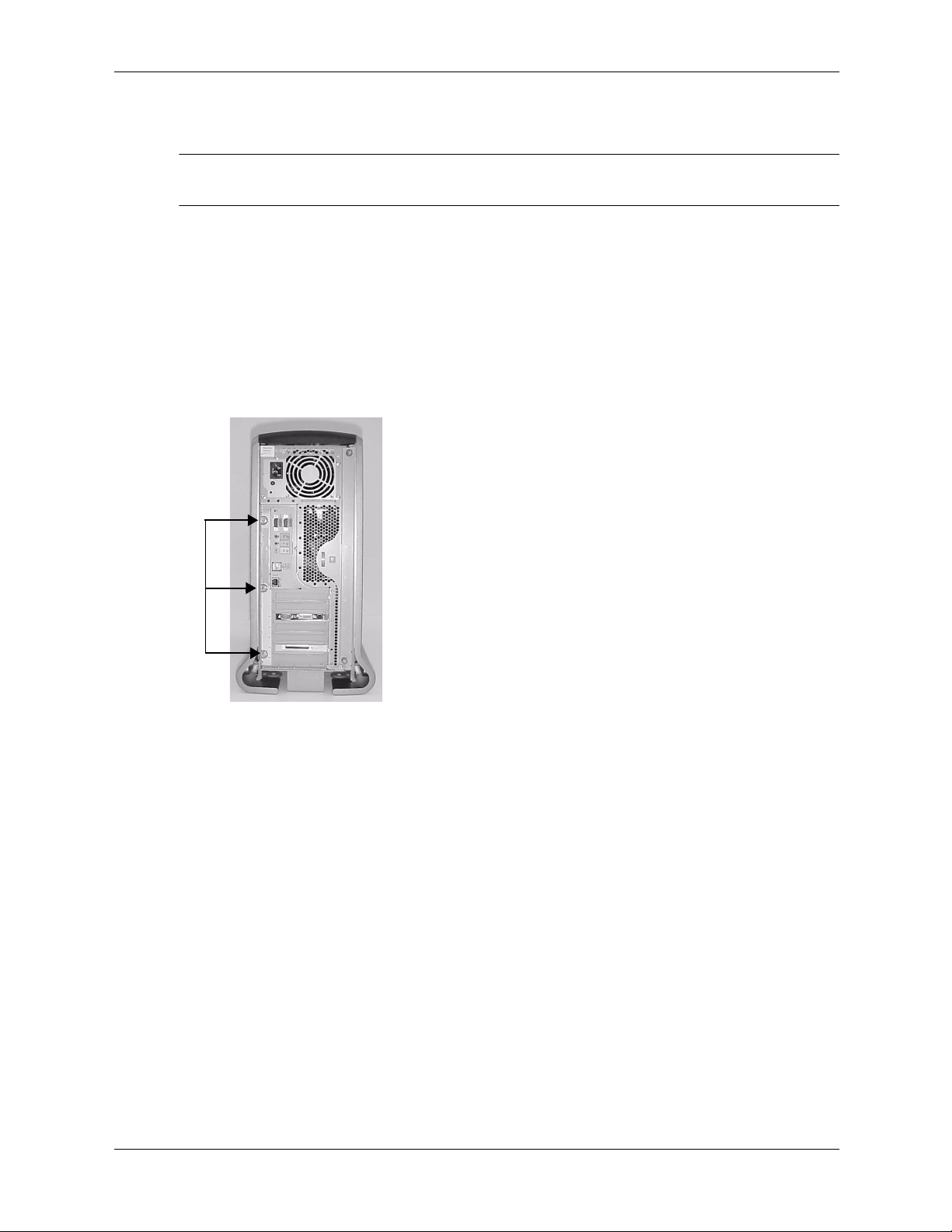
removing the shipping screws
The first time you open the case to work on the system, remove the screws that hold the hard
drive cage and AGP retainer arm in place for shipping. Replacing these screws is not necessary.
Installing or Replacing Parts and Accessories
Shipping Screws
technical reference guide 2–7
Page 24
Installing or Replacing Parts and Accessories
replacing the covers
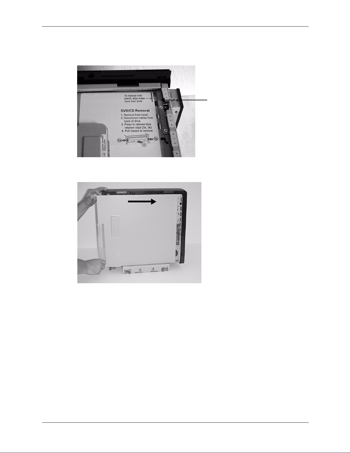
1. Align the right edge of the metal cover with the blue line on the system chassis.
Align the Metal Cover
2. Place the metal cover on the chassis and slide it toward the system front panel.
Replace the Metal Cover
3. Tighten the two blue screws on the cover near the rear panel of the chassis.
4. Rackmount system: Slide the system inward until the glide-rail retainers latch.
2–8 technical reference guide
Page 25
Installing or Replacing Parts and Accessories
5. Tower system: Replace the plastic cover.
a. Align the cover mounting holes with the matching tabs on the system chassis.
b. Close the cover until it snaps onto the system chassis.
B
A
Replacing the Plastic Cover (tower system only)
technical reference guide 2–9
Page 26
Installing or Replacing Parts and Accessories
removing and replacing the front bezel
You must remove the front bezel from the chassis to upgrade, remove or replace an optical drive.
removing the front bezel
1. To remove the front bezel:
❏
Tower system: Firmly grasp the finger grip at the top of the bezel and pull forward until
the bezel snaps open.
❏
Rack-mounted system: Remove the metal cover, then depress the blue release tabs inside
the chassis and rotate the bezel away from the chassis.
Removing the Front Bezel
2. Lift the bezel off of the chassis.
replacing the front bezel
1. Insert the bezel latches into the matching slots on the system chassis.
Replacing the Front Bezel
2. Close the bezel and push toward the front of the system until it snaps into place.
3. Rack-mounted system only: Replace the metal cover.
2–10 technical reference guide
Page 27
Installing or Replacing Parts and Accessories
removing and replacing internal components
memory modules
The hp workstation zx2000 has four memory sockets for memory modules. These modules can
be 256 MB, 512 MB, 1 GB or 2 GB. DIMMs must be installed in ordered pairs of equal size. You
can install between 512 MB and 8 GB of memory in the system. For a list of approved memory
modules, see Appendix C.
removing memory modules
1. Turn off the system, disconnect all cables, and remove the system covers.
WARNING: To ensure that memory modules are not damaged during removal or installation, power off
Å
the workstation and unplug the power cord from the AC power outlet. Wait until the LED on the back of
the power supply turns off before removing memory.
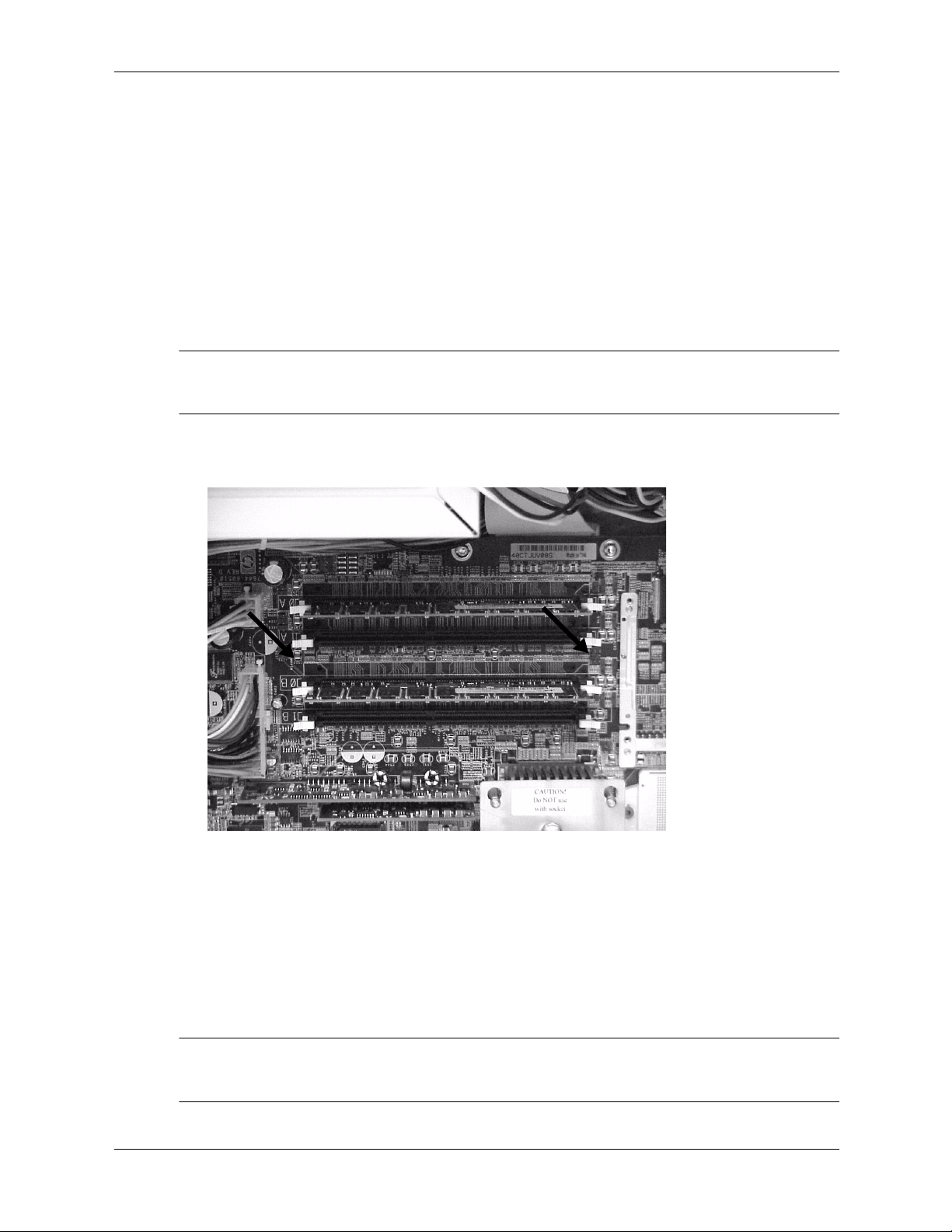
2. Press down on the memory module retainer clips and lift the module by its edges out of its
memory socket.
Memory Module Retainer Clips
3. If the removed memory is functional, store it in a static-free container for future use.
4. Replace the system covers, reconnect all cables, and turn on the system.
5. Execute the EFI shell info mem command to verify the new memory configuration.
For more information on EFI, see Chapter 3
installing memory modules
1. Turn off the system, disconnect all cables, and remove the system covers.
WARNING: To ensure that memory modules are not damaged during removal or installation, power off
Å
the workstation and unplug the power cord from the AC power outlet. Wait until the LED on the back of
the power supply turns off before removing or installing memory.
technical reference guide 2–11
Page 28

Installing or Replacing Parts and Accessories
2. Holding the memory module by its left and right edges, insert the module into the socket.
❏
DDR SDRAM must be loaded as matched pairs. For example, if you place a memory
module of 1 GB in DIMM 0A, you must insert a 1 GB module in DIMM 0B. Matched
pairs should be loaded in sockets 0A and 0B first, and then in sockets 1A and 1B.
❏
To verify that DIMMs are matched pairs, make sure the HP part numbers are identical.
❏
It is not necessary for DIMMs in the two pairs to match. For example, you may install a
pair of 256 MB DIMMs in sockets 0A and 0B and a pair of 1 GB DIMMs in sockets 1A
and 1B.
Location of power supply (reference point)
Loading Order Memory DIMM Sockets
1st DIMM 0A
2nd DIMM 1A
1st DIMM 0B
2nd DIMM 1B
NOTE: The memory modules are keyed and can only be inserted in one direction. When the
module is correctly seated, the retainer clips will return to their fully upright position. Snap the
clips firmly into place to ensure that the DIMMs are seated properly.
3. Replace the system covers, reconnect all cables, and turn on the system.
4. Execute the EFI shell info mem command to verify the new memory configuration.
For more information on EFI, see Chapter 3.
2–12 technical reference guide
Page 29
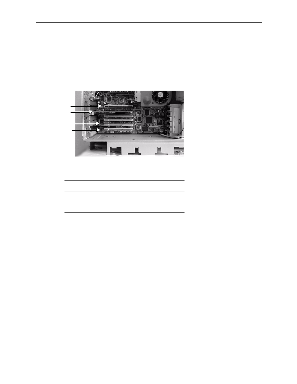
accessory and graphics cards
The zx2000 has the following accessory card sockets:
■
One half-length 64-bit 66 MHz PCI-X socket
■
One AGP-Pro 50 4X video card socket
■
Three full-length 64-bit 66 MHz PCI-X sockets
■
One full-length 64-bit 133 MHz PCI-X socket
1
2
3
4
Installing or Replacing Parts and Accessories
PCI and AGP Sockets
1 Half-length PCI socket
2 AGP-Pro 50 socket
3 66 MHz full-length PCI sockets (3)
4 133 MHz full-length PCI sockets
This section explains how to:
■
access the sockets, and
■
remove and replace AGP video and PCI accessory cards.
technical reference guide 2–13
Page 30
Installing or Replacing Parts and Accessories
removing an accessory or video card
1. Turn off the system, disconnect all cables, and remove the system covers.
2. Disconnect the hard drive power connection and IDE or SCSI cable.
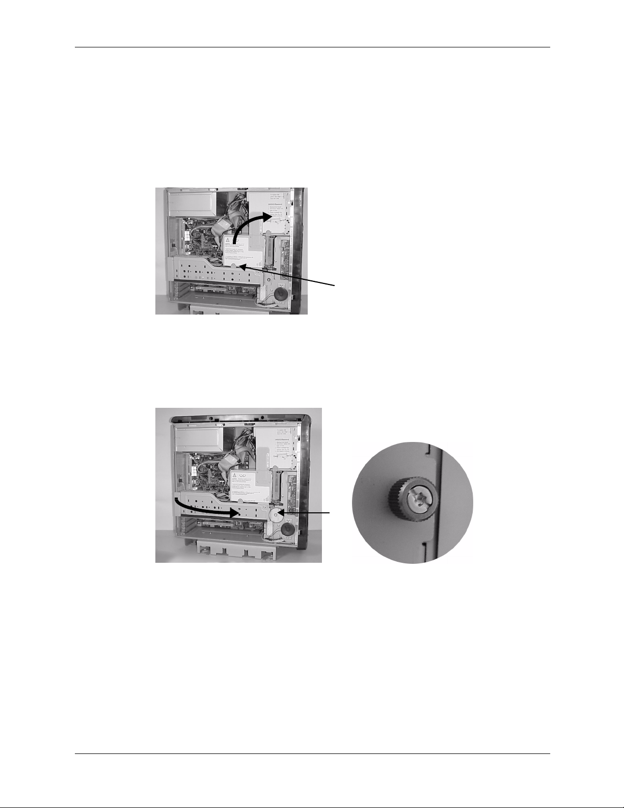
3. Raise the hard drive cage:
a. Depress the blue latch on the hard drive cage.
b. Lift up the hard drive cage until it snaps into the upright position.
B
Lifting the Hard Drive Cage
A
4. Remove the AGP retainer arm:
a. Unscrew the blue AGP retainer arm screw.
b. Lift the arm, sliding it slightly toward the front of the system to release the latches from
the slots in the chassis.
B
A
Removing the AGP Retainer Arm
2–14 technical reference guide
Page 31

Installing or Replacing Parts and Accessories
5. Pull the blue lever on the end of the retainer clip at the rear of the system and lift it out.
Removing the PCI Retainer Clip
6. Grasp the bulkhead end of the card and its opposite edge and lift the card out of its connector.
7. Insert a bulkhead blank, then replace the PCI retainer clip.
8. Replace the AGP retainer arm, making sure that the latches on the arm are inserted securely
into the slots on the rear edge of the system chassis and the retainer clip is securely holding
the AGP card in place. Lower the arm into place and tighten the blue screw.
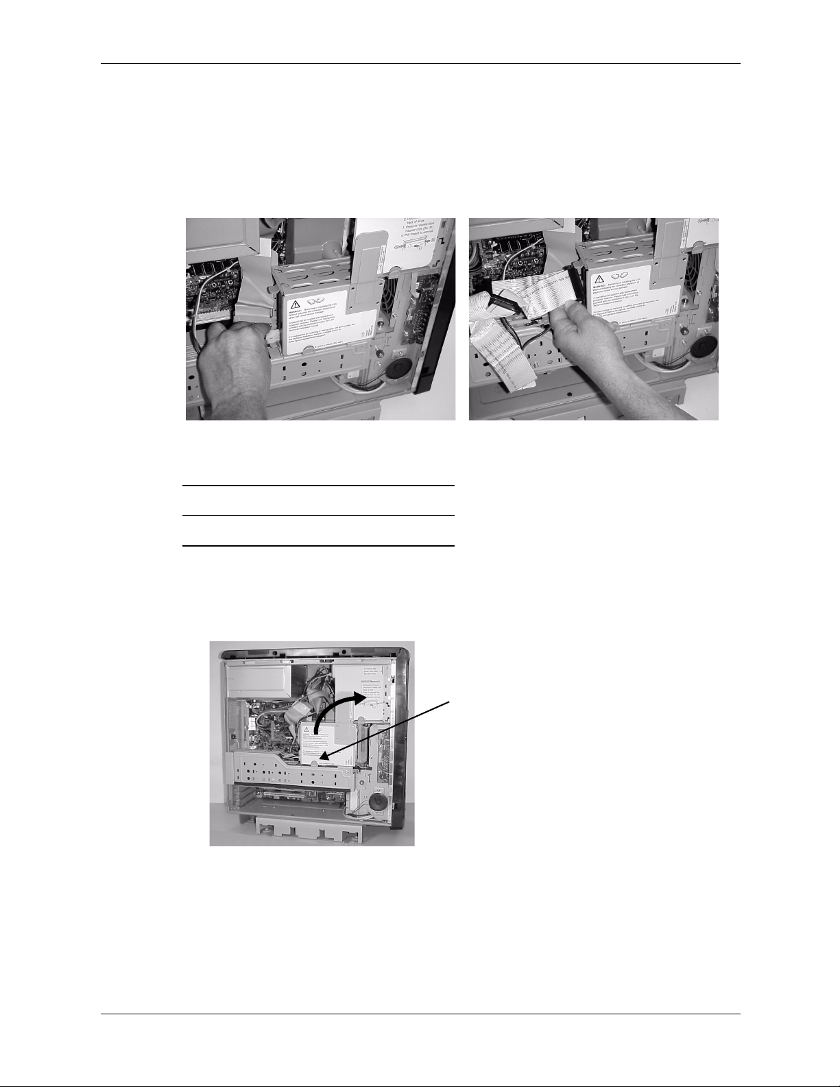
9. Close the hard drive cage:
a. Depress the blue latch holding the hard drive cage in the upright position.
b. Lower the cage until it snaps into place.
A
B
Releasing and Lowering the Hard Drive Cage
10. Reattach the hard drive power connection and IDE or SCSI cable.
11. Replace the system covers and cables, and restart the workstation.
technical reference guide 2–15
Page 32
Installing or Replacing Parts and Accessories
installing or replacing an accessory or video card
NOTE: For specifications on your video card, visit the manufacturer’s web site or refer to the
graphics documentation included in the acccessory kit.
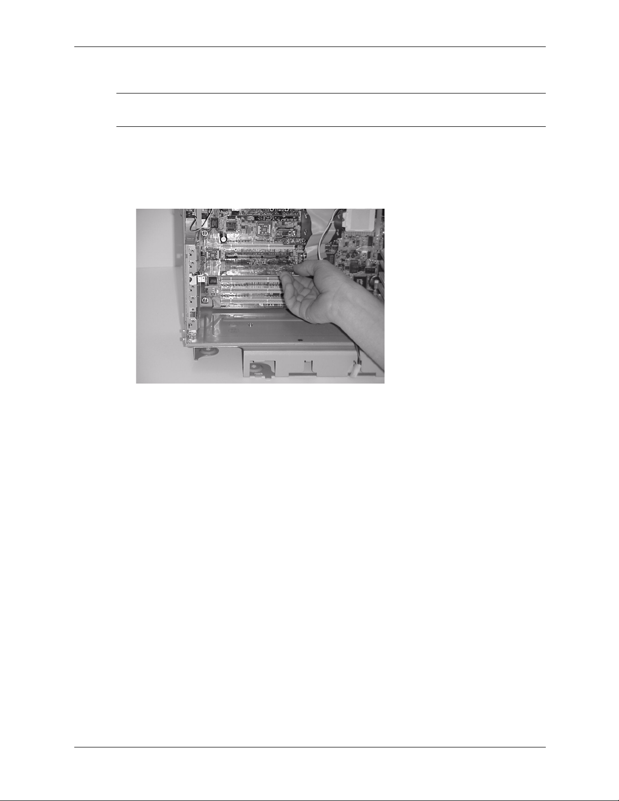
To install or replace an accessory or video card:
1. Remove the existing card or bulkhead blank that is in the socket you want to use.
2. Grasp the bulkhead end of the card and its opposite edge and insert the card into its
connector.
Insert the New Card
3. Replace the PCI retainer clip. First insert the tab at the lower end, then press down until the
blank snaps into place.
4. Replace the AGP retainer arm and lower the hard drive cage.
5. Replace the covers and reconnect all cables.
6. Turn the system on, then execute the EFI firmware shell info io command to verify that
the accessory card has been properly installed. For more information on EFI, see Chapter 3.
2–16 technical reference guide
Page 33
optical drives (CD or DVD)
removing an optical drive
1. Turn off the system, disconnect all cables, and remove the system covers and front bezel.
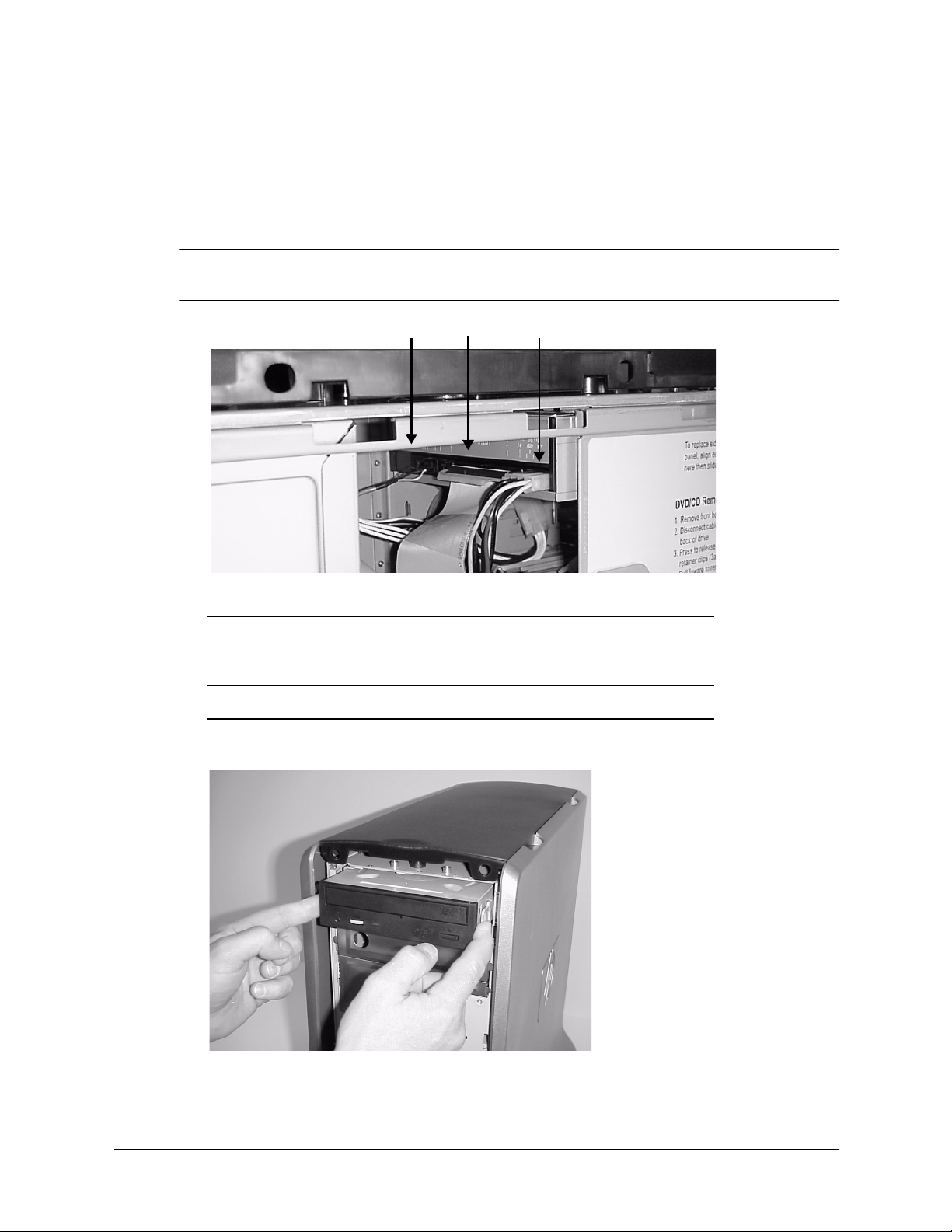
2. Disconnect the power, IDE and audio cables from the back of the optical drive.
NOTE: The audio cable has a small release clip on the side of the connector. Squeeze in on the
connector and pull gently to remove it from the drive.
Installing or Replacing Parts and Accessories
3
Disconnecting the Cables
1 Audio
2 IDE
3 Power
1
2
3. Release the small blue retainer clips on both sides of the optical drive by pressing in on them.
Releasing the Optical Drive Retainer Clips
4. Slide the optical drive forward and pull it out of the drive bay.
technical reference guide 2–17
Page 34

Installing or Replacing Parts and Accessories
5. Remove the rails from the drive by unscrewing the two screws on each rail.
Removing the Optical-drive Rail Screws
6. To save these rails for future use, attach them to the inside of the AGP retainer arm.
Rail Storage on AGP Retainer Arm
7. If you are not replacing the optical drive with a new drive, install a blank in the drive bay
opening.
replacing an optical drive
1. Turn off the system, disconnect all cables, and remove the system covers and front bezel.
2. Attach the rail labeled “L” to the left side of the optical drive and the rail labeled “R” to the
right side. Make sure the EMI gasket is installed on the top of the drive as shown:
EMI Gasket
3. Slide the optical drive into the drive bay until it stops.
4. Ensure that the retainer clips on both sides of the optical drive have snapped in place. To do
this, grasp both sides of the drive without pressing in on the retainer clips and pull. If you can
pull gently on the optical drive without it sliding out of its bay, the optical drive is securely in
place.
2–18 technical reference guide
Page 35

Installing or Replacing Parts and Accessories
5. Connect the IDE, power, and audio cables on the back of the optical drive.
NOTE: The system has two IDE cables — one is marked “Hard Drives,” the other is marked
“Optical Devices.” Make sure you connect them properly. The black connector on each cable is
for the master device; the gray connector is for the slave device. Make sure the jumper on the
optical drive is set to cable select (CSEL), not to master (M) or slave (S). See the documentation
provided with your drive for help locating the jumper.
6. Replace the covers and reconnect all cables.
7. Turn the system on, then execute the EFI shell info io command to verify that the optical
drive has been properly installed. For more information on EFI, see Chapter 3.
technical reference guide 2–19
Page 36
Installing or Replacing Parts and Accessories
hard drives
removing a hard drive
1. Turn off the system, disconnect all cables, and remove the system covers.
2. Disconnect the hard drive power connection and IDE or SCSI cable.
21
Disconnect the Drive Cables
1 Power cable
2 IDE or SCSI cable
3. Raise the hard drive cage:
a. Depress the blue latch.
b. Lift up the hard drive cage until it snaps into the upright position.
B
A
Lifting the Hard Drive Cage
2–20 technical reference guide
Page 37
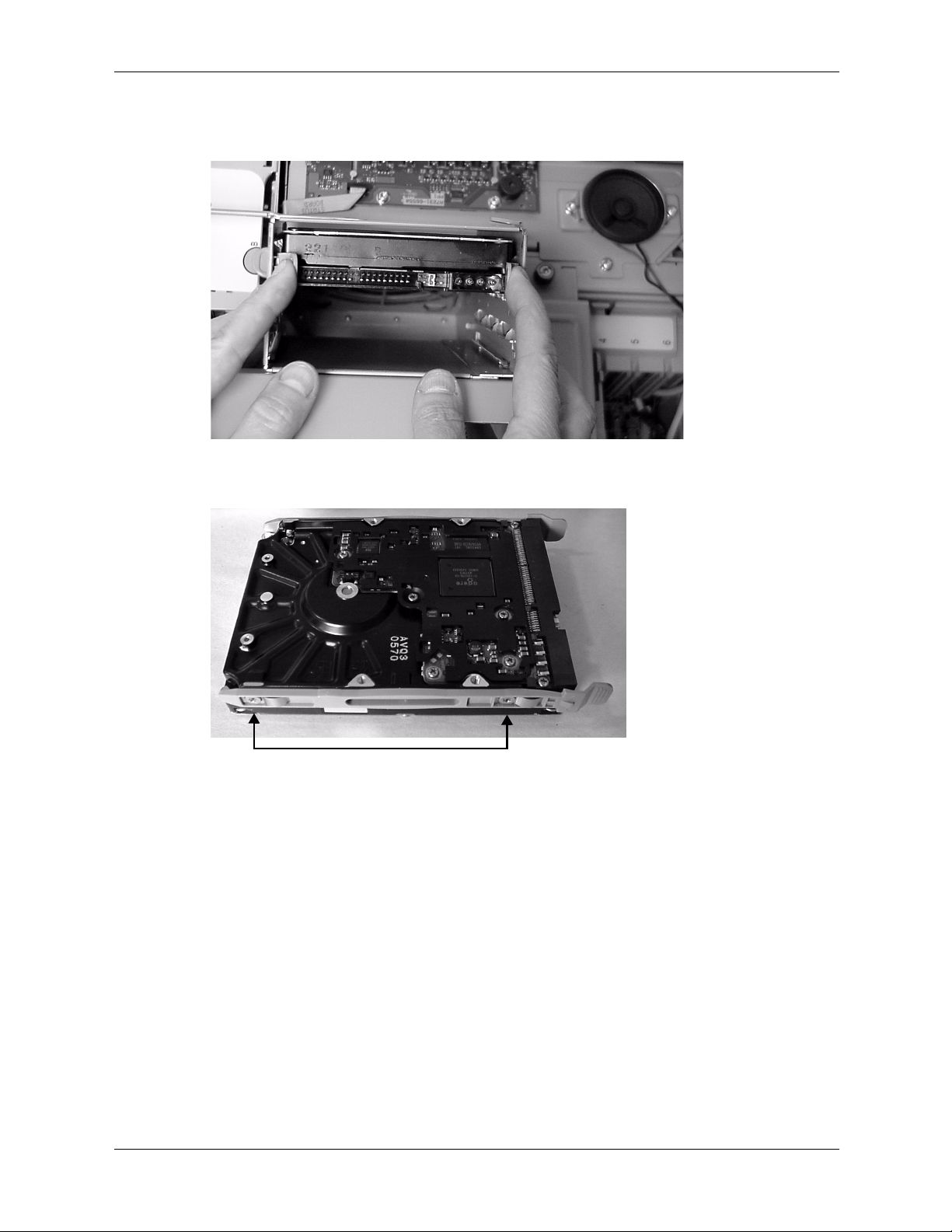
Installing or Replacing Parts and Accessories
4. Place your fingers on the colored release clips, located on the sides of the drive, and squeeze
inward. Then, pull outward to remove the drive from the system.
Removing the Hard Drive
5. Remove the rails from the hard drive by unscrewing the two screws on each rail.
Removing the Hard Drive Rail Screws
6. To save these rails for future use, attach them to the inside of the AGP retainer arm.
technical reference guide 2–21
Page 38
Installing or Replacing Parts and Accessories
replacing a hard drive
1. Attach rails to the hard drive (page 2-21).
NOTE: Extra hard drive rails are attached to the inside of the AGP retainer arm (page 2-18).
2. Push inward on the drive until it no longer slides inward.
3. If you removed the AGP retainer arm to access stored rails, replace it, making sure that the
latches on the arm are inserted securely into the sockets on the rear edge of the system
chassis and the retainer clip is securely holding the AGP card in place. Lower the arm into
place and tighten the blue screw using your fingers.
4. Depress the blue latch holding the hard drive cage in the upright position, and lower the cage
until it snaps into place.
5. Reattach the hard drive power connection and IDE or SCSI cable.
NOTE: The system has two IDE cables — one is marked “Hard Drives,” the other is marked
“Optical Devices.” Make sure you connect them properly. The black connector on each cable is
for the master device; the gray connector is for the slave device. Make sure the jumper on the
hard drive is set to cable select (CSEL), not to master (M) or slave (S). See the documentation
provided with your drive for help locating the jumper.
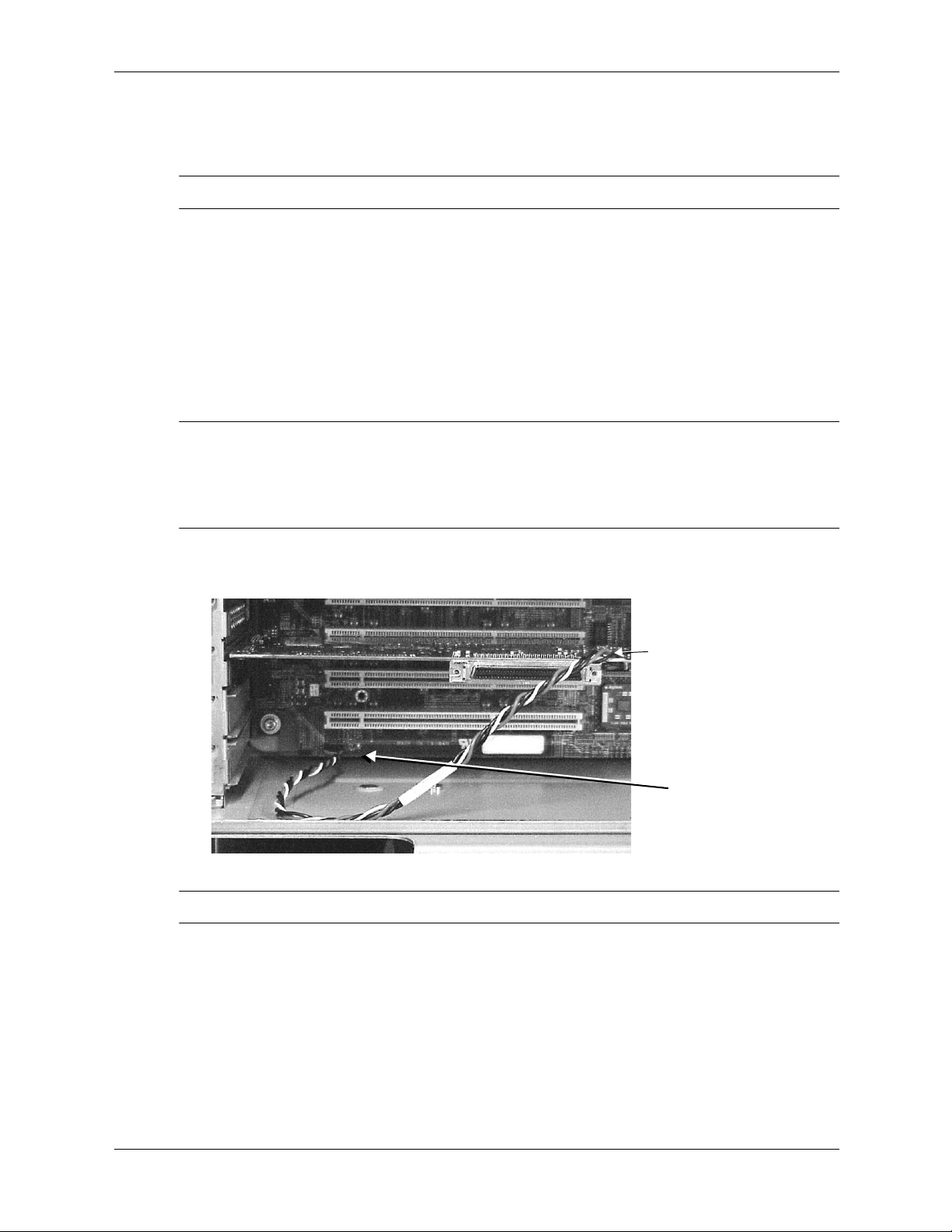
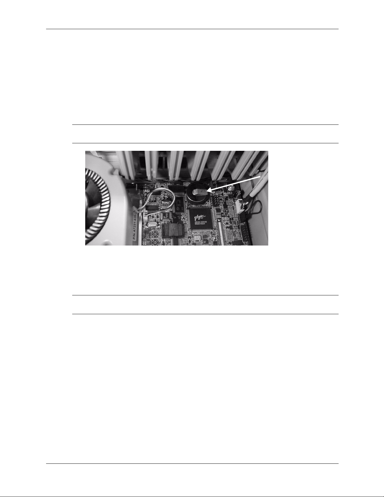
6. SCSI Drives only: Connect the SCSI Activity LED cable provided with the SCSI card to the
system board (A) and SCSI card (B).
B
A
Connect the SCSI LED Cable
NOTE: The SCSI Activity LED is only active on systems purchased after March 2003.
7. Replace the system covers and cables.
8. Turn the system on, then execute the EFI shell info io command to verify that the optical
drive has been properly installed. For more information on EFI, see Chapter 3.
2–22 technical reference guide
Page 39

power supply
removing the power supply
1. Turn off the system, disconnect all cables, and remove the system covers.
2. Unplug the power supply power connectors from all components in the system including the
hard drive, optical drive, CPU and motherboard (large and small connectors).
3. Unscrew the four screws attaching the power supply to the back of the system chassis.
Installing or Replacing Parts and Accessories
Unscrew the Power Supply
4. Pull the power supply forward and lift it out of the chassis.
Removing the Power Supply
replacing the power supply
1. Insert the new power supply into the system chassis.
2. Attach the four screws to the rear panel of the system.
3. Plug the power supply power connectors into all components in the system including the
hard drive, optical drive, CPU and motherboard (large and small connectors).
technical reference guide 2–23
Page 40
Installing or Replacing Parts and Accessories
system fans
Two cooling fans are mounted in a single removable module behind the system front bezel.
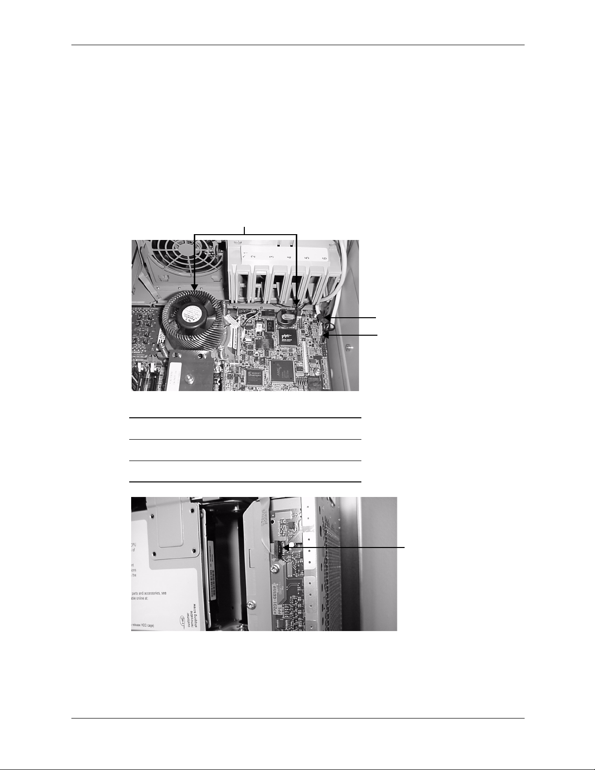
removing the system fans
1. Turn off the system, disconnect the power cable, and remove the system covers.
2. Remove the covers from the system, lift the hard drive cage, and remove the AGP retainer
arm.
3. Disconnect the two system fan power cables, as well as the speaker, front-access USB
connectors and the LED status panel.
1
2
Disconnecting the Fans and Cables
1 Two fan connectors (one behind CPU assembly)
2 Speaker connector
3 USB connector
3
Disconnecting the LED Status Panel Cable
2–24 technical reference guide
Page 41

Installing or Replacing Parts and Accessories
B
4. Unscrew the fan cover (A), lift it off of the fan enclosure (B), and move it to the side.
A
Removing the System Fan Cover
5. Grasp the fan enclosure firmly and pull it out of the system chassis.
Removing the System Fans
replacing the system fans
1. Grasp the replacement fan module firmly and insert it into its fan slot.
2. Re-attach the LED status panel and all cables, replace the system covers, and turn on the
system.
3. Verify that the fans have been properly installed by verifying that none of the Diagnostic
LEDs on the front of the system are lit.
technical reference guide 2–25
Page 42

Installing or Replacing Parts and Accessories
airflow guide
The airflow guide on your system ensures that the proper volume of air for cooling the voltage
regulator modules (VRMs), processor, and processor power module flows over these
components.
You may need to replace the airflow guide if it becomes damaged to the point that airflow across
the processor is restricted. You may need to remove the airflow guide to gain access to
components under it.
removing the airflow guide
1. Turn off the system and disconnect all power.
2. Disconnect all cables, and remove the system covers.
3. Raise the hard drive cage and remove the AGP retainer arm.
4. Lift the airflow guide out of the system chassis.
Airflow Guide
replacing the airflow guide
1. Insert the airflow guide so the CPU assembly fits into the opening in the guide.
2. Lower the hard drive cage, making sure it lowers fully and fits firmly against the airflow
guide and replace the AGP retainer arm.
3. Replace the system covers and reconnect all cables.
2–26 technical reference guide
Page 43

LED status panel
The LED status panel contains a set of LEDs and buzzer that provide status and troubleshooting
information.
CAUTION: Some system settings are saved to the LED status panel. If you are replacing both the LED
Ä
status panel and the system board, they must be replaced one at a time to avoid loss of system settings.
First replace one component, then turn on the system and boot to the EFI prompt. After confirming that the
first component has been replaced successfully, shut down the system and replace the second
component.
removing the LED status panel
1. Turn off the system, disconnect all cables, and remove the system covers.
2. Disconnect the LED status panel controller cable.
3. Unscrew the two LED status panel mounting screws and remove the panel.
Installing or Replacing Parts and Accessories
2
1
Disconnecting the LED Status Panel
1 Mounting screws
2 LED controller cable
3 LED status panel
replacing the LED status panel
1. Replace the LED status panel in the system and screw in the two LED status panel mounting
screws.
2. Connect the LED status panel controller cable.
3. Replace the system covers and reconnect all power cables. Turn on the system and verify that
the system and power LEDs light up.
3
technical reference guide 2–27
Page 44

Installing or Replacing Parts and Accessories
processor assembly and power module
CAUTION: You must follow these steps exactly and in the correct sequence to avoid serious
Ä
damage to the system.
removing a processor
1. Turn off the system, disconnect all power cables, and remove the system covers.
2. Raise the hard drive cage and remove the AGP retainer arm and airflow guide.
3. Disconnect the power module power cable.
1
Disc onnect the Power Module Power Cable
1 Power module
2 Power module cable
4. Unscrew the power module mounting screws, then disconnect the module from its processor
by sliding it toward the back of the system chassis.
2
Unscrewing and Removing the Power Module
5. Remove the power module from the system.
2–28 technical reference guide
Page 45

Installing or Replacing Parts and Accessories
6. Disconnect the small power cable for the processor turbo fan.
1
2
Disconnect the Power Cable for the Processor Turbo Fan
1 Turbo fan heatsink
2 Power connector for processor turbo fan
7. Use the special processor tool provided with the replacement processor to unscrew the four
captive heatsink screws.
Unscrew the Four Turbo Fan Captive Heatsink Screws
8. Slide the sequencing plate to the open position: towards the top (tower) or right side
(rackmount) of the system. This opens up the hole in the edge of the turbo fan’s heatsink for
insertion of the special processor tool into the processor locking mechanism.
Slide the Sequencing Plate This Way to Remove
technical reference guide 2–29
Page 46

Installing or Replacing Parts and Accessories
9. Unlock the processor locking mechanism using the special processor tool shipped with your
replacement processor assembly. To do this, you need to rotate the mechanism 180 degrees
counter-clockwise.
NOTE: There is a hole that runs down through the edge of the turbo fan’s heatsink, which allows
you access to the processor’s locking mechanism using the hex-key end of the special processor
tool.
2
3
4
1
Unlock the Processor Locking mechanism
1 Insert special processor tool here
2 The special processor tool rotates this lock underneath the heat sink
3 Unlocked
4 Locked
10. Lift the turbo fan heatsink and processor out of the system.
Remove the Turbo Fan Heatsink and Processor Assembly
2–30 technical reference guide
Page 47

replacing a processor
1. Remove the existing processor (page 2-28).
2. Make sure the processor locking mechanism is rotated into the unlock position.
Installing or Replacing Parts and Accessories
1
2
Processor Locking Mechanism
1 Unlocked
2 Locked
2
1
3. Use the four locator posts on the heatsink and the turbo fan power cable to properly align the
fan and processor assembly on the system board:
❏
The four locator posts fit in locator holes on the system board’s processor mount.
❏
The turbo fan’s power cable must be positioned so that it is located on the side of the
heatsink that faces the bottom (tower) or left side (rackmount) of the system.
1
2
Aligning the Turbo Fan and Processor Assembly
1 Locator posts
2 Locator holes
technical reference guide 2–31
Page 48

Installing or Replacing Parts and Accessories
4. Use the special processor wrench shipped with your replacement processor assembly to lock
the processor in place on the system board:
a. Insert the special processor tool into the hole that runs down the side of the heatsink and
rotate it clockwise 180 degrees. Remove the tool.
b. Slide the sequencing plate to the closed position.
Slide The Sequencing Plate This way to Install
c. Screw in the four captive heatsink screws.
5. Connect the small power cable for the processor turbo fan to its connector on the system
board.
6. Place the power module in the system.
7. Slide the power module on the system board’s metal mounting bracket so that the power
module’s connector connects with the processor’s connector. The two mounting screw holes
on the power module must align themselves with their screw holes on the system board’s
metal mounting bracket. Screw in the power module’s mounting screws.
8. Connect the power module power cable.
9. Replace the airflow guide. Replace the AGP retainer arm and lower the hard drive cage.
10. Replace the system covers and reattach all cables.
11. Verify that the processor works by turning the system.
2–32 technical reference guide
Page 49
system board
CAUTION: Some system settings are saved to the LED status panel. If you are replacing both the LED
Ä
status panel and the system board, they must be replaced one at a time to avoid loss of system settings.
First replace one component, then turn on the system and boot to the EFI prompt. After confirming that the
first component has been replaced successfully, shut down the system and replace the second
component.
removing the system board
1. Turn off the system, disconnect all cables, and remove the system covers.
2. Raise the hard drive cage and remove the AGP retainer arm.
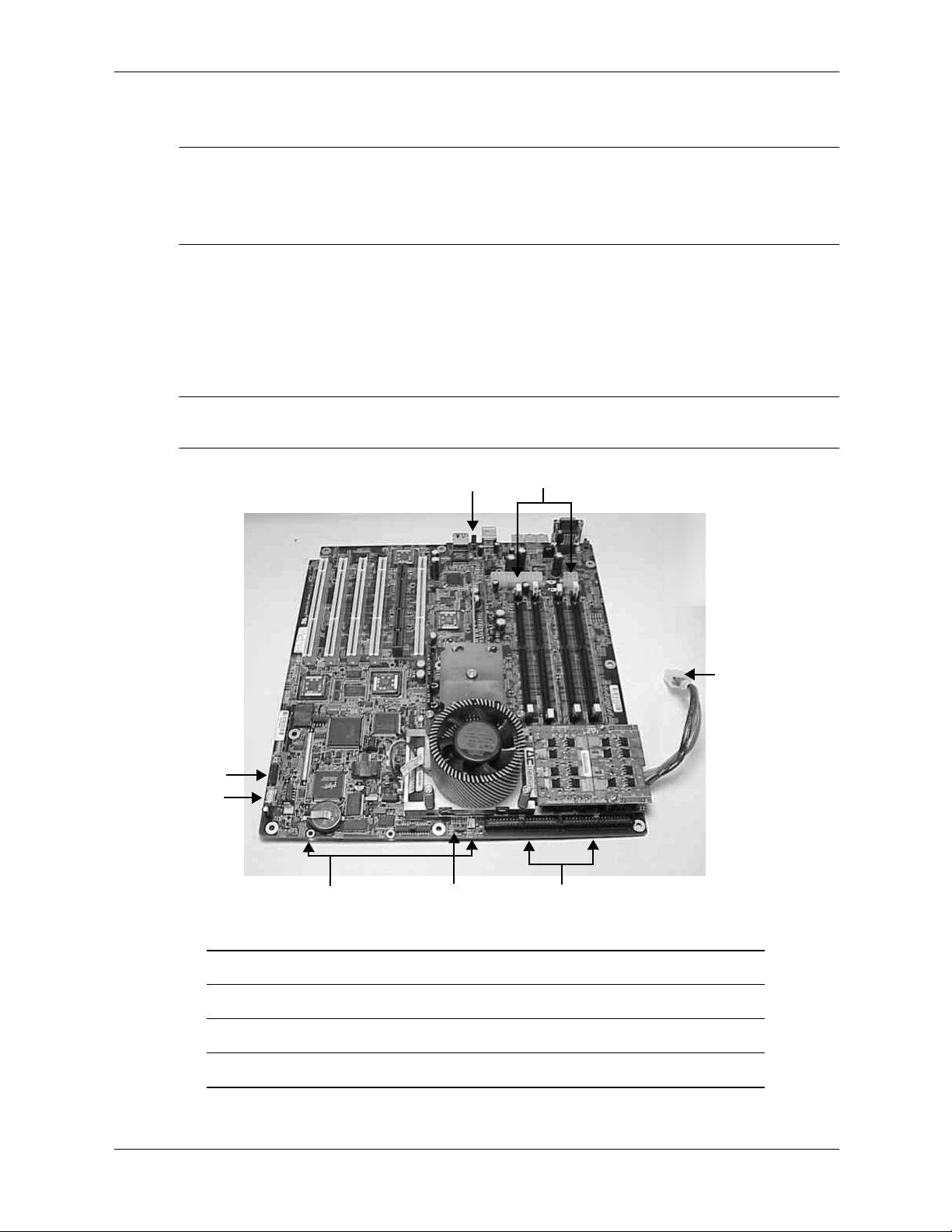
3. Disconnect the system board connectors.
NOTE: Disconnect the IDE cables from the hard disks and optical drives. Leave them attached
to the system board.
Installing or Replacing Parts and Accessories
B
A
H
System Board Connectors
G
C
D
E
F
A Front-access USB connectors E CPU power
B Speaker F IDE connectors
C Chassis intrusion switch G LED status panel connector
D System board power connectors H System fan connectors (2)
technical reference guide 2–33
Page 50
Installing or Replacing Parts and Accessories
4. Remove the following cables and components. Do not remove the CPU.
NOTE: To help with re-assembly, make note of which cables were connected to which
connector.
❏
DIMMs
❏
Accessory and video cards
❏
Fan, LED status panel and front-access USB connections
❏
Airflow guide
❏
Power connections and power supply
5. Unscrew the three backplane system board mounting screws that connect the system board
to the rear of the system chassis.
Unscrewing the System Board Mounting Screws
6. Grasp the chipset heatsink and the processor heatsink and slide the system board toward the
front of the system.
7. Lift up the rear edge of the system board and lift it out of the chassis.
2–34 technical reference guide
Page 51
replacing the system board
1. Complete all of the steps in the section “Removing the System Board” on page 2-33.
2. Grasp the new system board by its edges and carefully place it in the system. Remember that
the system board keyholes must be aligned with their corresponding standoffs on the
system’s chassis. Once the system board is in the system aligned with the keyhole standoffs,
slide it back toward the rear of the system. This locks the system board in place.
Aligning the System Board
3. Screw in the three rear backplane system board mounting screws.
4. Connect the system board cables.
Installing or Replacing Parts and Accessories
5. Replace all cables and components on the system board:
❏
Memory DIMMs
❏
IDE devices — hard drives and optical drives
❏
Accessory and graphics cards
❏
Fan, LED and front-access USB connections
❏
Airflow guide
❏
Power connections and power supply
6. Replace the AGP retainer arm, lower the hard drive cage. Replace the system covers and
reconnect the cables.
7. Verify that the processor works by turning the system.
technical reference guide 2–35
Page 52
Installing or Replacing Parts and Accessories
system battery
removing the system board battery
1. Turn off the system, disconnect all cables, and remove the system covers.
2. Raise the hard drive cage. Remove the AGP retainer arm and any PCI or AGP cards that are
blocking access to the battery.
3. Lift up on the battery and push on the back of it with a small flat-head screwdriver. This will
remove the battery from its holder.
CAUTION: Lift the battery just high enough to clear its holder. Too much stress on the retainer clip can
Ä
break it.
The System Board Battery Retainer Clip
replacing the system board battery
1. Lift up on the battery holder’s retainer clip with a small flat-head screwdriver and slide the
battery into its holder with your finger. The positive side of the battery should face up.
CAUTION: Lift the battery holder retainer clip just high enough to slide the battery into the battery
Ä
holder. Too much stress on the retainer clip can break it.
2. Replace any accessory cards you removed. Replace the AGP retainer arm and lower the hard
drive cage.
3. Replace the system covers and reconnect all cables.
4. Verify that the battery has been installed correctly by turning on the system and executing the
time command at the EFI prompt.
+
+
You may need to reset the system time and date using the EFI time and date commands.
Once you have set the time, turn the system off, unplug the power cord, and wait for a minute
before turning it back on. Execute the time and date commands again. If the time and date
are now correct, you have installed the battery correctly.
For details on using EFI commands, see Chapter 3.
2–36 technical reference guide
Page 53

system configuration
This chapter covers the tools available for configuring the hp workstation zx2000 system:
■
Extensible Firmware Interface (EFI), page 3-1
■
Baseboard Management Controller (BMC), page 3-23
■
Firmware upgrades, page 3-31
extensible firmware interface (EFI)
The Extensible Firmware Interface (EFI) is an interface between the operating systems and the
workstation firmware.
The following topics introduce you to the EFI and explain how to use it to configure your
system:
■
Accessing and navigating the EFI shell, page 3-2
■
Using the Boot Option Maintenance menu, page 3-11
3
■
Using the Security/Password menu, page 3-21
technical reference guide 3–1
Page 54

System Configuration
accessing and navigating the EFI shell
When you turn on your system and it begins to start up, your system pauses at the
boot option
screen:
EFI Boot Manager ver x.xx [xx.xx]
Please select a boot option
your OS will be listed here
[
EFI Shell [Built-in]
Boot option maintenance menu
Security/Password Menu
Use up and down arrows to change option(s).
Use Enter to select an option
]
NOTE: You have 7 seconds to change the boot option before the system boots to the default OS.
Use the up or down arrow keys to highlight an option, then press
■
EFI Shell [Built-in]
The
is a command line interface that allows you to operate the EFI
Enter
.
commands or create and run automated scripts.
Boot Option Maintenance Menu
■
allows you to select the order of the devices from
which you want the firmware to attempt to boot the OS. You can also configure the system to
boot from a configuration file.
Security/Password Menu
■
passwords.
remote access
You can also access the EFI remotely.
1. With the workstation turned off, connect a 9-pin to 9-pin serial cable to Serial Port A on the
rear panel of the workstation, and to your remote device.
2. Configure the terminal emulation software with these settings:
❏
Baud rate: 9600
❏
Bits: 8
❏
Parity: None
❏
Stop Bits: 1 (one)
❏
Flow Control: XON/XOFF
NOTE: The default terminal emulation type is VT100+. The default baud rate is 9600. These
settings can be changed from the EFI
3. Using the terminal emulation software, connect to the workstation with a direct connection.
4. Turn on the workstation and follow the steps below to access the EFI.
lets you add, change and delete system administrator and user
Boot Options Maintenance Menu
.
3–2 technical reference guide
Page 55

using the EFI shell
To access the EFI shell:
System Configuration
1. When the EFI boot option screen displays, use the arrow keys to highlight
Enter
press
.
EFI Shell
, then
NOTE: You have 7 seconds to change the boot option before the system boots to the default OS.
2. A list of file systems (drives and partitions), and block devices on hard drives is displayed.
For example:
Device mapping table
fs0: Acpi(HWP0002,100)/Pci(1|0)/Scsi(Pun0,Lun0)/HD(Part1,Sig00112233)
blk0: Acpi(HWP0002,0)/Pci(2|0)/Ata(Primary,Master)
blk1: Acpi(HWP0002,100)/Pci(1|0)/Scsi(Pun0,Lun0)
3. The EFI shell first searches for an optional script file named startup.nsh.
❏
If this file is found, it is executed automatically.
❏
If the script does not automatically start an OS or other application, the shell then waits
for commands to be entered at the command prompt.
4. You can now enter commands.
To run an individual command:
a. Type the command at the shell prompt. For example, to clear the display on the monitor
enter the
b. Press
cls
command:
Shell:> cls
Enter
to execute the command.
◆
Some commands require additional arguments to further define their action. For
example, to display information about the system memory, you must type the
info
command name (
fs0:\> info mem
◆
When you enter individual commands at the command prompt, the shell performs
), plus the desired category of information to display (
variable substitution, then expands wild cards before the command is executed.
◆
To switch to a different file system, execute the following, where
fsx
is the selected
file system, as listed on the screen (see step 2). For example:
Shell> fs0:
You see this prompt:
fs0:\> _
◆
You can also run EFI applications (files ending with
ls
current file system, run the
fs0:> ls
command. For example:
.efi
). To list applications in the
You see a list of applications on the fs0 file system.
mem
):
technical reference guide 3–3
Page 56

System Configuration
command syntax
The EFI shell uses a programming language to control the execution of individual commands.
Some characters have special meanings in the EFI shell. This section includes instructions for
running EFI shell commands and a list of the available commands.
To run an individual command:
1. Type the command at the shell prompt.
For example, to clear the display on the monitor:
fs0:\> cls
2. Press
Enter
to execute the command.
Arguments
Some commands require additional arguments to further define their action. For example, to
display information about the system memory, you must type the command name, plus the
desired category of information to display:
fs0:\> info mem
Rules
Follow these rules or the commands will not run correctly.
#
>
Denotes a comment. All text after this symbol is ignored.
Denotes an output redirect. Output of EFI shell commands can be saved to
files instead of being displayed on the monitor or in the terminal emulation
program. The shell redirects standard output to a single file and standard error
to a single file. Redirecting both standard output and standard error to the
same file is allowed. Redirecting to more than one file on the same command
is not supported.
The output redirect options, include:
>
redirect output to a unicode file
>a
redirect output to an ASCII file
>>
>>a
append output to a unicode file
append output to an ASCII file
The syntax for redirecting script output is:
Command > output_file_pathname
%
Denotes an environment variable. Environment variables can be set and
set
viewed through the use of the set command (see
command in this chapter).
To access the value of an environment variable as an argument to a shell
command, delimit the name of the variable with the
after the variable name; for example,
*
?
3–4 technical reference guide
Denotes a wildcard character. Matches zero or more characters in a file name.
Denotes a wildcard character. Matches exactly one character of a file name.
%myvariable%
%
character before and
.
Page 57

System Configuration
[
^
“ ”
space
newline
Denotes a wildcard character. Defines a set of characters; the pattern matches
any single character in the set. Characters in the set are not separated. Ranges
of characters can be specified by specifying the first character in a range, then
-
the
character, then the last character in the range. For example:
[a-zA-Z]
Denotes a literal argument. When a command contains a defined alias the
alias
shell replaces the alias with its definition (see
^
If the argument is prefixed with the
character, however, the argument is
command in this chapter).
treated as a literal argument and alias processing is not performed.
Quotation marks in the EFI shell are used for argument grouping. A quoted
string is treated as a single argument to a command, and any whitespace
characters included in the quoted string are just part of that single argument.
Quoting an environment variable does not have any effect on the
de-referencing of that variable. Double quotation marks (“ ”) denote strings.
Single quotation marks are not treated specially by the shell in any way.
Empty strings are treated as valid command line arguments.
Used to format batch scripts to separate command names, parameters and so
forth.
Used to format batch scripts. Each line represents a new command.
technical reference guide 3–5
Page 58

System Configuration
command descriptions
The following sections provide brief descriptions of the EFI commands. For more information,
use the EFI shell’s help system. To access a:
■
List of EFI command classes, execute help at the EFI shell prompt.
■
Detailed description of a command, execute help and the command name or other options
at the EFI shell prompt. For example:
❏
fs0:\> help date displays help for the date command
❏
fs0:\> help -a displays all commands in alphabetical order
❏
fs0:\> help -a-b displays all commands in alphabetical order with page breaks
❏
fs0:\> help class displays all commands in the specified command class (see
below)
Command Classes
EFI commands are organized into different classes based on their functions. The classes include:
boot
configuration
device
memory
shell
scripts
Get device, driver and handle information
Boot options and disk-related commands
Change and retrieve system information
Memory related commands
Basic shell navigation and customization
EFI shell script commands
Boot Commands
The boot class commands let you set boot and disk options.
autoboot
bcfg
dblk
boottest
mount
reset
vol
View or set autoboot timeout variable
Display/modify the driver/boot configuration
Display the contents of blocks from a block device
Set/view BootTest bits
Mount a file system on a block device
Reset the system
Display volume information of the file system
Configuration Commands
The configuration class commands let you change and retrieve system information.
cpuconfig
date
err
errdump
info
3–6 technical reference guide
Deconfigure or reconfigure CPUs
Display the current date or sets the date in the system;
format is
mm/dd/yyyy
Display or change the error level
View/clear logs
Display hardware information
Page 59

System Configuration
monarch
palproc
salproc
time
ver
View or set the monarch processor
Make a PAL procedure call
Make a SAL procedure call
Display the current time or set the time of the system; format is
Display the version information
Device Commands
The device class commands provide device, driver and handle information.
baud
connect
devices
devtree
disconnect
dh
driver
drivers
drvcfg
Set serial port settings
Bind an EFI driver to a device and start the driver
Display the list of devices being managed by EFI drivers
Display the tree of devices that follow the EFI Driver Model
Disconnect one or more drivers from a device
Display the handles in the EFI environment
List and install ROM-based drivers
Display the list of drivers that follow the EFI Driver Model
Invoke the Driver Configuration Protocol
hh:mm:ss
drvdiag
guid
lanaddress
load
loadpcirom
map
openinfo
pci
reconnect
unload
Invoke the Driver Diagnostics Protocol
Display all the GUIDs in the EFI environment
Display core I/O MAC address
Load and optionally connect EFI drivers
Load a PCI Option ROM
Display or define mappings
Display the protocols on a handle and the agents
Display PCI devices or PCI function configuration space
Reconnect one or more drivers from a device
Unload a protocol image
Memory Commands
The memory class commands let you manage your memory.
default
dmpstore
dmem
memmap
Reset all NVM values to system defaults
Display all NVRAM variables
Display the contents of memory
Display the memory map
mm
pdt
technical reference guide 3–7
Display or modify memory, memory-mapped IO and PCI settings
View or clear the Page Deallocation Table (PDT)
Page 60

System Configuration
Shell Commands
The shell class commands let you navigate and customize your shell.
alias
attrib
cd
cls
comp
cp
edit
eficompress
efidecompress
exit
help
hexedit
ls
mkdir
mode
mv
Display, create, or deletes aliases in the EFI shell
Display or change the attributes of files or directories
Display or change the current directory
Clear the standard output with an optional background color
Compare the contents of two files
Copy one or more files/directories to another location
Edit an ASCII or UNICODE file in full screen
Compress a file
Uncompress a file
Exit the EFI shell
Display help menus, command list, or verbose help of a command
Edit with hex mode in full screen
Display a list of files and subdirectories in a directory
Create one or more directories
Display or change the mode of the console output device
Move one or more files/directories to destination
rm
set
setsize
touch
type
xchar
Delete one or more files or directories
Display, create, change or delete EFI environment variables
Set the size of the file
Update the specified file with the current time
Display the contents of a file
Turn on/off extended character features
Scripts Commands
The scripts class commands let you use shell scripts.
echo
for/endfor
Make batch file execution jump to another location
goto
if/endif
pause
stall
Display messages or turn command echoing on or off
Execute commands for each item in a set of items
Execute commands in specified conditions
Print a message and suspends for keyboard input
Stalls, or pauses, the processor for the specified time in microseconds
3–8 technical reference guide
Page 61

EFI scripts
The EFI scripting language allows you to create executable shell scripts. You can place a set of
EFI commands in the shell script, then execute the script as often as needed. You also can modify
the script to make it perform different tasks. Script files can be either unicode or ASCII format.
Note that commands executed from a batch script are not saved by the shell for DOSkey history
(up-arrow command recall).
The optional script startup.nsh is automatically executed when you enter the EFI shell
environment. All EFI shell scripts have the “.nsh” suffix.
This section provides a brief explanation of how to create, edit and run an EFI shell script.
To create or edit a shell script:
1. At the EFI shell prompt, run the shell’s editor. Execute:
System Configuration
fs0:\> edit
file.nsh
where file.nsh represents the name of the new shell script you are creating or the existing
script you want to edit.
2. Type or edit the commands to be executed when the script is run. For example:
echo This is a test file.
3. When you are finished writing the script: press F2 to save the file, then press F3 to exit the
editor.
The EFI editor is controlled by function key commands. A menu of available commands is
shown at the bottom of the screen. If you are accessing the editor through a terminal emulator
and the function keys do not work, use the escape sequences listed here.
Command Function Key Escape Sequence
Open file F1 Esc 0
Save file F2 Esc S
Exit F3 Esc Q
Cut F4 Esc D
Paste F5 Esc P
Goto F6 Esc G
Search F7 Esc F
Replace F8 Esc R
File type F9 Esc T
To run a shell script:
1. Type the name of the command at the EFI shell prompt. For example:
fs0:\> mytest.nsh
2. Press
technical reference guide 3–9
Enter
.
Page 62

System Configuration
positional arguments
Up to nine positional arguments are supported for batch scripts. Positional argument substitution
is performed before the execution of each line in the script file. Positional arguments are denoted
%n
by
currently being executed.
In batch scripts, argument substitution is performed first, then variable substitution. Thus, for a
variable containing
argument on the command line. If no real argument is found to substitute for a positional
argument, then the positional argument is ignored.
, where n is a digit between 0 and 9. By convention, %0 is the name of the script file
%2
, the variable will be replaced with the literal string %2, not the second
For example, this sample script replaces the two literal arguments
positional arguments
echo -off
set arg1 %1
set arg2 %2
echo "I found a %arg1%"
echo "I also found a %arg2%"
To run the command, type the command name followed by the arguments at the shell
prompt:
fs0:\efi\tools> example cat dog
example> echo -off
I found a cat
I also found a dog
nesting
Script file execution can be nested; that is, script files may be executed from within other script
files. Recursion is allowed.
output redirection
Output redirection is fully supported. Output redirection on a command in a script file causes the
output for that command to be redirected. Output redirection on the invocation of a batch script
causes the output for all commands in the batch script to be redirected to the file, with the output
of each command appended to the end of the file.
%1
and
%2
arg1
and
arg2
with the
:
By default, both the input and output for all commands executed from a batch script are echoed
to the console. Display of commands read from a batch file can be suppressed via the echo -off
command (see echo). If output for a command is redirected to a file, then that output is not
displayed on the console.
error handling in scripts
By default, if an error is encountered during the execution of a command in a batch script, the script
will continue to execute. The
lasterror
shell variable allows batch scripts to test the results of the
most recently executed command using the if command. This variable is not an environment variable,
but is a special variable maintained by the shell for the lifetime of that instance of the shell.
comments in script files
Comments can be embedded in batch scripts. The # character on a line denotes that all characters
#
on the same line and to the right of the
to the console.
3–10 technical reference guide
are to be ignored by the shell. Comments are not echoed
Page 63

using the boot option maintenance menu
This menu allows you to select console output and input devices as well as various boot options.
It contains the following items:
Boot from a File
■
Add a Boot Option
■
■ Delete Boot Option(s)
Change Boot Order
■
Manage BootNext setting
■
Set Auto Boot TimeOut
■
Select Active Console Output Devices
■
Select Active Console Input Devices
■
Select Active Standard Error Devices
■
Cold Reset
■
Exit
■
These items are described in the following sections.
In all menus, to:
System Configuration
■
display the help available for the command, select
■
return to the main Boot Options Maintenance menu, select
■
select an item, use the arrow keys to highlight the item, then press
■
save your changes, select
Save Settings to NVRAM
Help
Exit
Enter
NOTE: The options shown below are examples, each system will have different options
available based on the system configuration and installed hardware components
technical reference guide 3–11
Page 64

System Configuration
paths
All devices in the zx2000 are represented by paths in the EFI shell. To identify the correct socket
or disk drive, use the following tables.
Accessory Card Sockets
Socket Path
1 PCI Acpi(HWP0002,400)/pci(1|0)
2 AGP Acpi(HWP0003,0)/pci(0|0)
3 PCI Acpi(HWP0002,400)/pci(2|0)
4 PCI Acpi(HWP0002,400)/pci(3|0)
5 PCI Acpi(HWP0002,400)/pci(4|0)
6 PCI Acpi(HWP0002,600)/pci(1|0)
Systems with IDE Drives
Drive Path
IDE hard drive Acpi(HWP0002,500)/Pci(2|0)/Ata(Primary,Master)
IDE hard drive Acpi(HWP0002,500)/Pci(2|0)/Ata(Primary,Slave)
Removable media boot Acpi(HWP0002,500)/Pci(2|0)/Ata(Secondary,Master)
Removable media boot Acpi(HWP0002,500)/Pci(2|0)/Ata(Secondary,Slave)
Systems with SCSI Drives
Drive Path
SCSI hard drive Acpi(HWP0002,400)/Pci(3|0)/Scsi(Pun0,Lun0)
SCSI hard drive Acpi(HWP0002,400)/Pci(3|0)/Scsi(Pun1,Lun0)
Removable media boot Acpi(HWP0002,500)/Pci(2|0)/Ata(Secondary,Master)
3–12 technical reference guide
Page 65

boot from a file
Use this option to manually run a specific application or driver.
NOTE: This option boots the selected application or driver one time only. When you exit the
application, you will return to this menu.
This option displays the file systems that are on your server or workstation and lets you browse
these file systems for applications or drivers that are executable. Executable files end with the
.efi
extension. You can also select remote boot (LAN) options that have been configured on
your network.
For example:
Boot From a File. Select a Volume
NO VOLUME LABEL [Acpi(HWP0002,500)/Pci(2|0)/Ata(Primary,Master)/
CD_FORMAT [Acpi(HWP0002,500)/Pci(2|0)/Ata(Secondary,Master)/CDRO
Removable Media Boot [Acpi(HWP0002,500)/Pci(2|0)/Ata(Secondary,M
Load File [EFI Shell [Built-in]]
Load File [Acpi(HWP0002,500)/Pci(3|0)/Mac(00306E385AFB)]
Exit
In this example:
System Configuration
NO VOLUME LABEL
■
is an IDE hard drive. When you format a hard drive, the EFI tools
provide an option to LABEL the disk. In this example, the volume was not labelled.
CD_FORMAT
■
Removable Media Boot
■
is the label created for the disk currently inside the DVD-ROM drive.
allows you to boot from a removable media drive (CD/DVD
drive). This option does not support booting from a specific file on a specific removable
media disc.
■
The two
Load Files
are the EFI Shell and the LAN.
technical reference guide 3–13
Page 66

System Configuration
add a boot option
Use this option to add items to the EFI boot menu.
This option displays the file systems that are on your workstation and lets you browse these file
systems for applications or drivers that are executable. Executable files end with the
extension. You can also select remote boot (LAN) options that have been configured on your
network. The option you have selected will be added to the EFI boot menu.
When adding a boot option that already exists in the Boot Manager list of boot option, you can
choose whether to create a new option or modify the existing one:
■
If you choose to modify an existing option, you may change the boot option name and/or add
boot option arguments to the existing option.
■
Creating a new boot option for an already existing option allows multiple instances of the
same boot option to exist.
For example:
Add a Boot Option. Select a Volume
NO VOLUME LABEL [Acpi(HWP0002,500)/Pci(2|0)/Ata(Primary,Master)/
Removable Media Boot [Acpi(HWP0002,500)/Pci(2|0)/Ata(Secondary,M
Load File [EFI Shell [Built-in]]
Load File [Acpi(HWP0002,500)/Pci(3|0)/Mac(00306E385AFB)]
Exit
In this example:
.efi
■
Most of the items are the same options in
NO VOLUME LABEL
■
bootable applications to add to the Boot Manager list of Boot options.
Removable Media Boot
■
device.
Load File EFI Shell
■
is for adding a network boot option.
delete boot option(s)
Use this option to remove boot option from the EFI boot menu.
NOTE: This does not delete any files, applications or drivers from your system.
This option displays a list of boot options that are configured on your workstation. The names
will match the options on the main Boot Manager menu (above).
■
To delete an item from the list, use the arrow keys to highlight the item and press
■
To remove all of the entries from the EFI boot menu, select
setting may be used as a security device on systems that are accessed remotely.
Boot From a File
.
is the IDE hard drive. You can search through the IDE disk for
will treat the Removable Media (generally a CD) as a bootable
adds a new instance to the EFI Shell, Load File with the MAC address
Enter
.
Delete All Boot Options
. This
3–14 technical reference guide
Page 67

change boot order
Use this option to change the order of boot options. The order in which options are listed in the
EFI boot menu also reflects the order in which the system attempts to boot. If the first boot
option fails, the system will try booting the second, then the third, and so forth, until a boot
option succeeds or until all options have failed.
For example, if you normally boot using a configuration on your LAN but would like to boot
from a local hard drive if the LAN is unavailable, move the LAN boot option to the top of the
list, followed by the hard drive boot option.
The Menu lists boot options that currently exist in the main Boot Manager menu. You can change
the priority of the items by moving them up or down in the list:
■
Press U to move an option up.
■
Press D to move an option down.
■
Save changes to modify the order in the Boot Manager menu, which modifies the order that
the Boot Manager will attempt to boot the options.
■
The items at the bottom of the screen (shown in bold in these examples) are descriptions of
the selected option.
For example:
Change boot order. Select an Operation
EFI Shell [Built-in]
Current OS
Save Settings to NVRAM
Help
Exit
System Configuration
VenHw(D65A6B8C-71E5-4DF0-A909-F0D2992B5AA9)
Boot0000
technical reference guide 3–15
Page 68

System Configuration
manage bootnext setting
Use this option to run the selected boot option immediately upon entering the main Boot
Manager menu. This option is useful for booting an option that only needs to be booted once,
without changing any other setting in the main Boot Manager menu. This is a one-time operation
and does not change the permanent system boot settings.
This option displays the file systems that are on your workstation and lets you browse these file
systems for applications or drivers that are executable. Executable files end with the
extension. You can also select remote boot (LAN) options that have been configured on your
network.
.efi
To restore the default boot next setting, select
For example:
Manage BootNext setting. Select an Operation
EFI Shell [Built-in]
Current OS
Reset BootNext Setting
Save Settings to NVRAM
Help
Exit
set auto boot timeout
Use this option to set the amount of time the system will pause before attempting to launch the
first item in the Boot Options list.
For example:
Set Auto Boot Timeout. Select an Option
Set Timeout Value
Delete/Disable Timeout
Help
Exit
Interrupting the timeout during the countdown stops the Boot Manager from loading any boot
options automatically. If there is no countdown then boot options must be selected manually.
Reset BootNext Setting
.
■
To set the auto boot timeout value, in seconds, select
Set Timeout Value
and enter the
desired value.
■
To disable the timeout function, select
Delete/Disable Timeout
.
NOTE: When this option is selected, the system will not automatically boot. The system will
stop at the EFI boot menu and wait for user input.
3–16 technical reference guide
Page 69

select active console output devices
Use this option to define the devices that will display output from the system console. This list
normally includes the VGA monitor and a serial port for directing output to a terminal emulation
package.
NOTE: If you are installing a modem in your system, make sure you disable the modem serial
port from the Active Console Input and Active Console Output device lists.
NOTE: Some Operating Systems support multiple consoles, such as a simultaneous serial and
VGA output. This is not supported for HP-UX. See your OS documentation to determine how
many consoles are supported with your system.
For example:
Select the Console Output Device(s)
Acpi(PNP0501,0)/Uart(9600 N81)/VenMsg(PcAnsi)
Acpi(PNP0501,0)/Uart(9600 N81)/VenMsg(Vt100)
* Acpi(PNP0501,0)/Uart(9600 N81)/VenMsg(Vt100+)
Acpi(PNP0501,0)/Uart(9600 N81)/VenMsg(VtUtf8)
* Acpi(HWP0003,0)/Pci(0|0)
Save Settings to NVRAM
Exit
* indicates a currently selected device.
System Configuration
This menu is identical to
Console Error Devices
. The zx2000 does not support different
configurations for Output and Error console. For correct operation:
■
When changes are made to either Output or Error console menus, the identical change must
be made in both menus.
■
When changing serial devices, changes must be made to Output, Input, and Error menus for
proper operation.
technical reference guide 3–17
Page 70

System Configuration
To select: Choose:
Serial A/Serial 1 Acpi(PNP0501,0)/Uart(9600 N81)/VenMsg(Vt100+)
AGP Graphics Port Acpi(HWP0003,0)/Pci(0|0)
■
Each option is identified with an EFI Device path. Not all options will be available,
depending on the configuration of the system and the options purchased. Device paths may
differ slightly on different product models.
■
On both serial device examples, UART 9600 indicates the current baud rate of the serial
device. This can be changed with the EFI
emulation type. Several different terminal emulation protocols are supported (see list above).
■
Only one terminal emulation type (PcANSI, Vt100, etc.) can be selected for each serial
console, but multiple serial consoles can be selected at a time.
baud
command. VenMsg Vt100+ is the current
3–18 technical reference guide
Page 71

select active console input devices
Use this option to define the devices that will be used to provide input to the system console.
This option displays the console devices on your workstation. This may include a standard
keyboard or a serial port for receiving output from a terminal emulation package. Several
different terminal emulation protocols are supported.
■
When changing serial devices, changes must be made to Output, Input, and Error menus for
proper operation.
NOTE: If you are installing a modem in your system, make sure you disable the modem’s serial
port from the Active Console Input and Active Console Output device lists.
For example:
Select the Console Input Device(s)
Acpi(PNP0501,0)/Uart(9600 N81)/VenMsg(PcAnsi)
Acpi(PNP0501,0)/Uart(9600 N81)/VenMsg(Vt100)
* Acpi(PNP0501,0)/Uart(9600 N81)/VenMsg(Vt100+)
Acpi(PNP0501,0)/Uart(9600 N81)/VenMsg(VtUtf8)
* Acpi(HWP0002,0)/Pci(1|0)
Save Settings to NVRAM
Exit
* indicates a currently selected device.
System Configuration
■
Each option is identified with an EFI Device path. Not all options will be available,
depending on the configuration of the system and the options purchased. Device paths may
differ slightly on different product models.
■
On both serial device examples, UART 9600 indicates the current baud rate of the serial
baud
device. This can be changed with the EFI
command. VenMsg Vt100+ is the current
emulation type. Several different terminal emulation protocols are supported (see list above).
■
Only one terminal emulation type (PcAnsi, Vt100, etc.) can be selected for each serial
console, but multiple serial consoles can be selected at a time.
To select: Choose:
Serial A/Serial 1 Acpi(PNP0501,0)/Uart(9600 N81)/VenMsg(Vt100+)
USB Keyboard Acpi(HWP0002,0)/Pci(1|0)
technical reference guide 3–19
Page 72

System Configuration
select active standard error devices
Use this option to define the devices that will display error messages from the system console.
This menu is identical to
Console Output Devices
. The zx2000 does not support different
configurations for Output and Error console. For correct operation:
■
When changes are made to either Output or Error console menus, the identical change must
be made in both menus.
■
When changing serial devices, changes must be made to Output, Input, and Error menus for
proper operation.
3–20 technical reference guide
Page 73
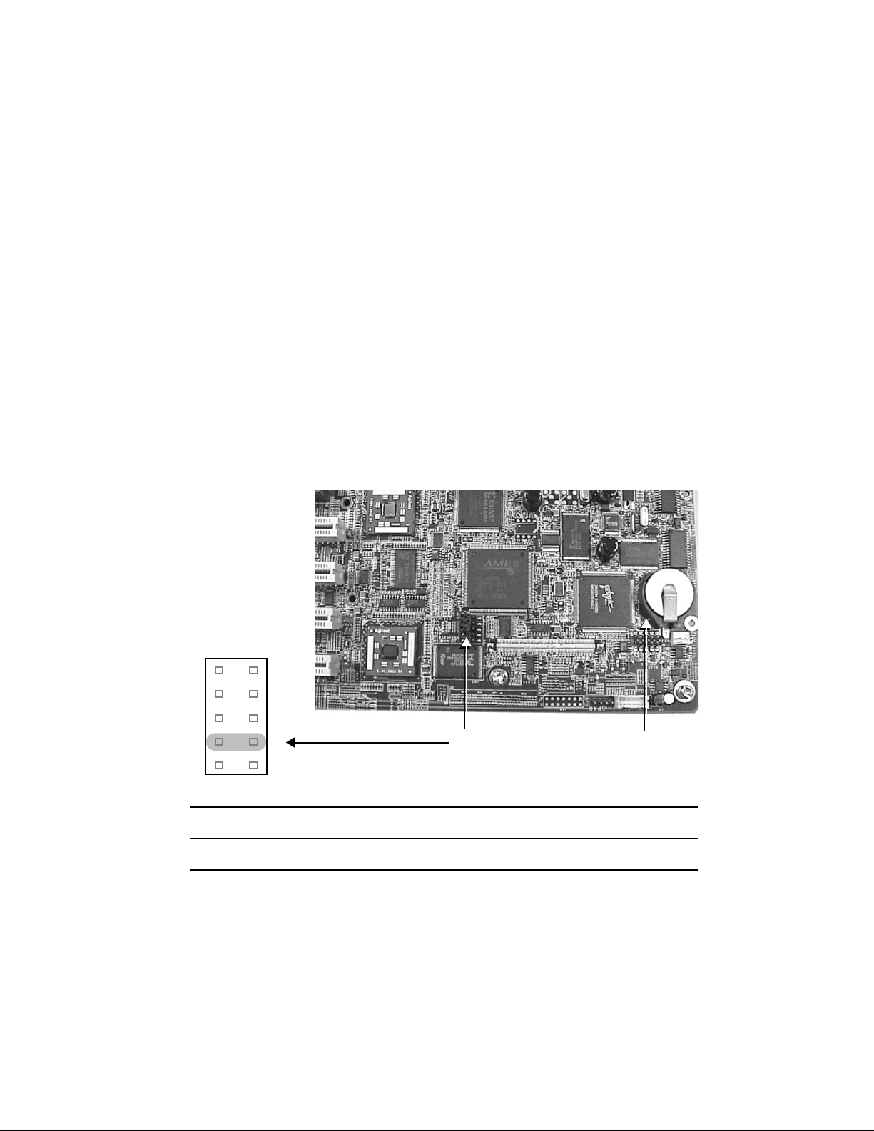
using the security/password menu
To change the administrator and user passwords:
System Configuration
1. Select
Security/Password Menu
.
2. Select either:
Set Administrator Password
❏
Set User Password
❏
3. Select:
Set Administrator Password
❏
Enable/disable Password
❏
Help
❏
for assistance
4. When you are finished, select
Exit
Set User Password
or
to set a new password
to specify whether a password is required
.
If you forget your passwords, they can be reset using a jumper on the system board.
To reset the system passwords:
1. Power down the system and unplug the AC power cord.
2. Place a jumper between pins 7 and 8 on J47 on the system board.
78
Password Reset Jumper and BMC Heartbeat LED
1 J47
2 BMC heartbeat LED (between BMC and battery)
technical reference guide 3–21
21
Page 74

System Configuration
3. Plug in the AC power cord and wait for the BMC heartbeat LED to start blinking green. This
should take about 5 seconds from the time you plug in the power cord.
4. Unplug the AC power cord again and remove the jumper.
5. Plug in the power cord and boot the system.
The passwords have been cleared. Follow the instructions above to set new system
passwords.
NOTE: Store the system in a secure location and keep the system case locked at all times to
protect against unauthorized access.
Attach the Lock to the Latch on the Case
3–22 technical reference guide
Page 75

baseboard management controller (BMC)
This section explains the BMC command-line interface. Topics include:
■
Using the BMC command line interface (CLI), page 3-23
■
BMC commands, page 3-24
using the BMC command line interface (CLI)
To log in to the BMC command line interface, use a serial connection and terminal emulation
software:
1. With the workstation turned off, connect a null-modem cable to Serial Port 1 on the rear
panel of the workstation (see page 17), and to your remote device.
2. Configure the terminal emulation software with these settings:
❏
Baud rate: 9600
❏
Bits: 8
❏
Parity: None
❏
Stop Bits: 1 (one)
System Configuration
❏
Flow Control: XON/XOFF
NOTE: The default terminal emulation type is VT100+. Terminal emulation for the BMC cannot
be changed. The default baud rate is 9600. This setting can be changed using the EFI
baud
command.
3. Using the terminal emulation, connect to the workstation with a direct connection.
4. To access the BMC command line interface, press
For example, on a U.S. QWERTY keyboard, press
Esc (
Esc
, then press
Shift
and 9 at the same
time.
5. If prompted, enter the user or admin password at the login prompt:
login>
If no password is defined, you are not prompted for one.
NOTE: If AC power is connected to the system, this command activates the BMC command line
interface even if the workstation power is off.
6. The BMC prompt displays. If you entered the admin password, you have full access. If you
entered the user password, you have restricted access.
Admin Session Initiated
cli>
or
User Session Initiated
cli>
technical reference guide 3–23
Page 76

System Configuration
logging out of the BMC command line interface
When you are finished using the BMC CLI:
1. If you have a system password set, execute the following to log out of the BMC without
returning to the system console:
Q
The BMC login prompt displays:
login>
2. To log out of the BMC and return to the system console, press
Shift
and Q at the same time).
BMC commands
overview
The Baseboard Management Controller supports the industry-standard Intelligent Platform
Management Interface (IPMI) specification. This specification describes the management
features that have been built into the system board. These features include: diagnostics (local and
remote), console support, configuration management, hardware management, and
troubleshooting.
There are two categories of BMC commands:
■
Simple commands
■
Intelligent Platform Management Interface (IPMI) commands
This section provides a brief overview of the available commands. For detailed information, see
the Intel web site:
Executing BMC Commands
To execute BMC commands at the command prompt:
■
Type the command and any required parameters after the cli> prompt.
Esc Q
http://www.intel.com/design/servers/ipmi
(press
Esc
, then press
■
Use the
■
Press
3–24 technical reference guide
Backspace
Enter
to execute the command.
key to correct mistakes.
Page 77

simple commands
Simple IPMI commands allow you to control the BMC interface, view logs, get help, and change
your password.
To execute simple BMC commands:
1. Type the first letter or letters of the command, as indicated in the table below, followed by
any required options. For example, to execute the Change Password command, type
System Configuration
C
.
2. Press
Enter
to execute the command.
3. If prompted, enter the additional information, such as a new password, and press
example:
cli> c
Type the new password> ****
Retype the new password> ****
New password confirmed.
cli>
Command
syntax Options Mode Description
C
FPL
H
INFO
LOC [0, 1]
Prompts user for
new password
N/A User Reads the forward progress log. This log is
N/A User Displays a list of BMC commands.
N/A User Displays the BMC firmware revision.
0=off
1=on
User Lets you change the password.
encoded and can be used by HP support
representatives. For additional information see
“SEL and FPL log entries” on page D-4.
User Turns the system locator LED on or off
(rack mount systems only).
Enter
. For
P [0, 1]
Q
RS
SD
SE
technical reference guide 3–25
0=off
1=on
N/A User Logs out user; does not close BMC session. Only
N/A User Resets the system.
N/A User Displays the SDR repository. This data is
N/A User Displays system event log (SEL). This log is
User Forces system power on or off; does not shut
down using OS procedures. If you do not enter
a parameter, displays the current power state.
applies if passwords are set.
encoded and can be used by HP support
representatives.
encoded and can be used by HP support
representatives. For additional information see
“SEL and FPL log entries” on page D-4.
Page 78

System Configuration
IPMI commands
IPMI commands allow you to communicate with and configure various components of the
system. IPMI commands are available only to users with Admin level access.
CAUTION: If IPMI commands are sent incorrectly to certain registers, the system board may be
Ä
damaged and need to be replaced.
All IPMI commands require a sequence of hex codes used as parameters. Each command may
include some or all of the following parameters:
■
Network Function and Lun (NetFnLun). The NetFn parameter identifies the message
category. The LUN value is always 0.
■
Command. The messages specified in this document contain a one-byte command field.
Commands within each category are unique. Command values can range from 00h through
FDh. FEh is reserved for future extension of the specification, and FFh is reserved for
message interface level error reporting on potential future interfaces.
■
Data. The Data field carries the additional parameters for a request or a response, if any.
The IPMI commands can be entered in long or short forms. The associated response from the
BMC matches the form of the command.
For example:
■
Short format, or ipmi, command:
❏
Syntax:
ipmi NetFnLun Cmd Data1 Data2 ... DataN
❏
Sample command and system response:
cli> ipmi 18 04
00 55 00
cli>
■
Long format, or i, command:
❏
Syntax:
i 0 NetFnLun 0 0 0 Cmd Data1 Data2 ... DataN 0
❏
Sample command and system response:
cli> i 20 18 c8 f0 04 04 08
F0 1C F4 20 04 04 00 55 00 83
cli>
3–26 technical reference guide
Page 79

System Configuration
Long format IPMI commands (“I”) use an ASCII transcription of the IPMI data format.
NOTE: All non-command bytes can be replaced with 0.
Long Format IPMI Command Data Structures
Bits Byte
7-2 1-0
rsSa = 0x20 0x20
NetFn = 0x07 rsLUN = 0x00 0x18
Checksum = 0xC8 0xC8
rqSWID = 0xF0 0xF0
rqSeq = 0x01 rqLUN = 0x00 0x04
Cmd = 0x04 0x04
Checksum = 0x08 0x08
Long Format IPMI Response Data Structure
Bits Byte
7-2 1-0
rqSWID = 0xF0 0xF0
NetFn = 0x07 rsLUN = 0x00 0x1C
Checksum = 0xF4 0xF4
rsSA = 0x20 0x20
rqSeq = 0x01 rsLUN = 0x00 0x04
Cmd = 0x04 0x04
Data byte 1 = 0x00 (completion code) 0x00
Data byte 2 = 0x55 (result = no error) 0x55
Data byte 3 = 0x00 (details) 0x00
Checksum = 0x83 0x83
technical reference guide 3–27
Page 80

System Configuration
The BMC supports the version 1.0 IPMI categories and commands listed in the following tables.
For detailed information on the IPMI specification and commands, see the Intel web site:
http://www.intel.com/design/servers/ipmi
Command Categories
NetFn NetFn << 2 Description
00, 01 00, 04 Chassis
04, 05 10, 14 Sensor/Event (S/E)
06, 07 18, 1C Application
0A, 0B 28, 2C Storage
32, 33 C8, CC HP Custom (proprietary)
Chassis Commands
Command Description
01h Get chassis status
02h Chassis control
0Fh Get Power-on Hours (POH) counter
06h Set Power Restore Policy
Sensor/Event Commands
Command Description
01h Get event receiver
02h Platform event (a.k.a. “Event Message”)
28h Set sensor event enable
29h Get sensor event enable
2Ah Re-arm sensor events
2Dh Get sensor reading
3–28 technical reference guide
Page 81

Application Commands
Command Description
IPM Device “Global” Commands
01h Get device ID
02h Cold reset
03h Warm reset
04h Get self test results
Broadcast Commands
01h Broadcast ‘Get Device ID’
System Interface Commands
2Eh Set BMC global enables
2Fh Get BMC global enables
System Configuration
30h Clear message flags
31h Get message flags
32h Enable message channel receive
33h Get message
34h Send message
35h Read event message buffer
36h Get BT interface capabilities
technical reference guide 3–29
Page 82

System Configuration
Command Description
BMC Watchdog Timer Commands
22h Reset watchdog timer
24h Set watchdog timer
25h Get watchdog timer
Storage Commands
Command Description
SEL Commands
40h Get SEL info
41h Get SEL allocation info
42h Reserve SEL
43h Get SEL entry
44h Add SEL entry
47h Cl ea r S EL
48h Get SEL time
49h Set SEL time
SDR Repository Commands
20h Get SDR repository info
21h Get SDR repository allocation info
22h Reserve SDR repository
23h Get SDR
28h Get SDR repository time
29h Set SDR repository time
FRU Inventory Device Commands
10h Get FRU inventory area info
11h Read FRU inventory data
12h Write FRU inventory data
3–30 technical reference guide
Page 83

firmware upgrades
To update the system and BMC firmware:
System Configuration
1. Download the firmware update from
http://www.hp.com/go/bizsupport
Follow the menu prompts to navigate to the support page:
◆
Select
download drivers/ software
◆
Enter the product name in the search field (
◆
Select the search result.
◆
Choose the firmware release you need to download.
◆
Click the i information icon for instructions on how to download, unpack, and install
.
the firmware upgrade:
2. Download, unpack and install the firmware upgrade.
3. Execute the
info fw
EFI command to confirm that the upgrade was successful.
hp workstation zx2000
.
).
technical reference guide 3–31
Page 84

System Configuration
3–32 technical reference guide
Page 85

This chapter contains the following sections, which describe how to identify and solve common
problems you may encounter when using your hp workstation zx2000:
■
Troubleshooting overview, page 4-1
■
Identifying and diagnosing hardware problems, page 4-2
■
Running Diagnostic Software Tools, page 4-15
troubleshooting overview
The hp workstation zx2000 includes several tools to help you troubleshoot potential problems.
Many problems have simple solutions, so try the tools and suggestions covered in this section
before contacting HP support. The following sections provide additional information about:
■
The system e-buzzer
■
The LEDs
■
Monitor troubleshooting
4
troubleshooting
technical reference guide 4–1
Page 86

Troubleshooting
identifying and diagnosing hardware problems
Should a hardware failure occur, the zx2000 LEDs, e-buzzer, and logs will help you identify the
problem:
System beeps and e-buzzer. The Workstation zx2000 has an e-buzzer that beeps in specific
■
patterns to identify errors when the system boots. The e-buzzer can also send encoded data
over the phone to help support representatives identify more complex problems.
LEDs. The lights on the front bezel of the workstation change color and blink in different
■
patterns to help identify specific hardware problems.
■
The System Event Log (SEL) and Forward Progress Log (FPL) provide additional
detailed information about errors identified by the e-buzzer and LEDs. (See “SEL and FPL
log entries” on page 4.)
If the LEDs, e-buzzer, and logs do not provide enough information for you to identify the
problem you are experiencing, HP also provides software diagnostic tools.
4–2 technical reference guide
Page 87

system e-buzzer
If a problem is detected at any time when the system is booting or running, the e-buzzer emits
audible beeps and an encoded error message.
■
The audible beeps consist of a modem-like sound repeated 3 times, followed by 0-7 beeps of
a single frequency at 1-second durations, each separated by 1 second. The e-buzzer emits a
different number of beeps for each type of error. More detailed information is provided by
the LEDs.
■
The electronic signal can be sent through a telephone line to an authorized help desk or HP
Support. This signal can be decoded by help desk equipment to extract the workstation
model, serial number and details about any faults. To send this signal to HP Support, hold
your telephone next to the LED 1 on the system front bezel when the system is booting.
The e-buzzer does not report all problems, only the problems listed below. If the e-buzzer
indicates an error, check the SEL (page D-4) for a more detailed explanations of the failure.
Number of
Beeps Component Description
1 Processor Processor absent or not correctly connected. Reseat or replace
Troubleshooting
processor.
2 Power Supply Power supply failure. Replace power supply.
3 Memory No memory, bad memory modules or incompatible memory
module. Check memory module loading order. Reseat or
replace memory modules.
4 Graphics Card Graphics card problem. Reseat or replace the graphics card.
5 PCI Card PCI card problem. Reseat or replace the PCI card.
6 Critical System
Failure
7 System Board Defective system board. Contact support.
Two minutes has elapsed after the BMC starts system power and
no BOOT_START event is logged in the SEL. Possible problems
include:
•Clock is bad
• System board problem
• CPU connection to the board bad
• CPU power pod failure
•CPU failure
• Corrupt Firmware (bad code, or improper update)
Contact support.
NOTE: See Chapter 2 for detailed instructions on removing and replacing system components.
technical reference guide 4–3
Page 88

Troubleshooting
The e-Buzzer may also be activated by several other events:
■
■
The power button on the front panel operates differently depending on how long the button is
pressed and whether or not the system was on or off when the button was pressed.
■
■
If the system firmware detects an error during system operation, the BMC will trigger the
e-Buzzer to sound.
If you miss the beep code count during the initial transmission sequence, trigger the
sequence again by pressing and holding the system power button for 3-5 seconds and release
it as soon as the sound begins.
When the system power is off:
❏
1-3 seconds. System power turns on. The e-buzzer beeps if an error is encountered.
❏
3-5 seconds. The e-buzzer repeats the last stored error.
When the system power is on and the system is at the EFI:
❏
1-3 seconds. System power turns off immediately.
❏
3-5 seconds. The e-buzzer repeats the last stored error.
❏
5 seconds or longer. System power turns off immediately.
■
When the system power is on and the OS is running:
❏
1-3 seconds. System power turns off via ACPI signal to OS (soft power-down).
❏
3-5 seconds. The e-buzzer repeats the last stored error.
❏
5 seconds or longer. System power turns off immediately (hard power-down).
4–4 technical reference guide
Page 89

LEDs
Several LEDs are on the front bezel of the workstation. See the following sections for a detailed
description of these functions.
power and system LEDs
The power and system LEDs indicate the overall state of the system:
Power LED System LED State
Off Off Off or on Standby
On (green) Solid green Running normally
On (green) Blinking green (1/sec.) Booting
On (green) Blinking orange (1/sec.) Attention (See “<$elemtext7)
On (green) Blinking red (2/sec.) Fault (See “<$elemtext7)
activity LED
Troubleshooting
The Activity LED indicates the state of disk and drive activity on the system.
Activity LED State
Off Off or no current disk/drive activity
Blinking (green) Disk/drive is being accessed
NOTE: The Activity LED is only active on systems purchased after March 2003.
NOTE: The Activity LED automatically communicates with IDE HDD or optical drives. To
communicate with SCSI drives, a SCSI LED activity cable must connect the SCSI card and the
system board.
technical reference guide 4–5
Page 90

Troubleshooting
LAN LEDs (back panel)
The four LAN LEDs on the back panel of the system indicate LAN activity.
LAN LED Location Color State
1. Gbit Tower: Right Off No 1000 mb/s link
Rack-mounted: Top Green Indicates link at 1000mb/s LAN port
2. 100mb Tower: 2nd from right Off No 100 mb/s link
Rack-mounted: 2nd from top Green Indicates link at 100mb/s LAN port
3. Link Tower: 2nd from left Off No LAN connection
Rack-mounted: 2nd from
bottom
4. Activity Tower: Left Off No LAN activity
Rack-mounted: Bottom Green Flashing or solid green LED indicates
Green Link connectivity on LAN port
activity on LAN port
locator LED and button (rack-mounted systems only)
If you have several similar systems on a rack, you may find it difficult to identify a specific
computer requiring maintenance. The locator LED is designed to help identify the workstation in
a rack.
The locator LED can be activated and deactivated by pressing the locator button on the front
bezel of the system. The LED can also be accessed remotely using the BMC interface. See
“<$elemtext23.
4–6 technical reference guide
Page 91
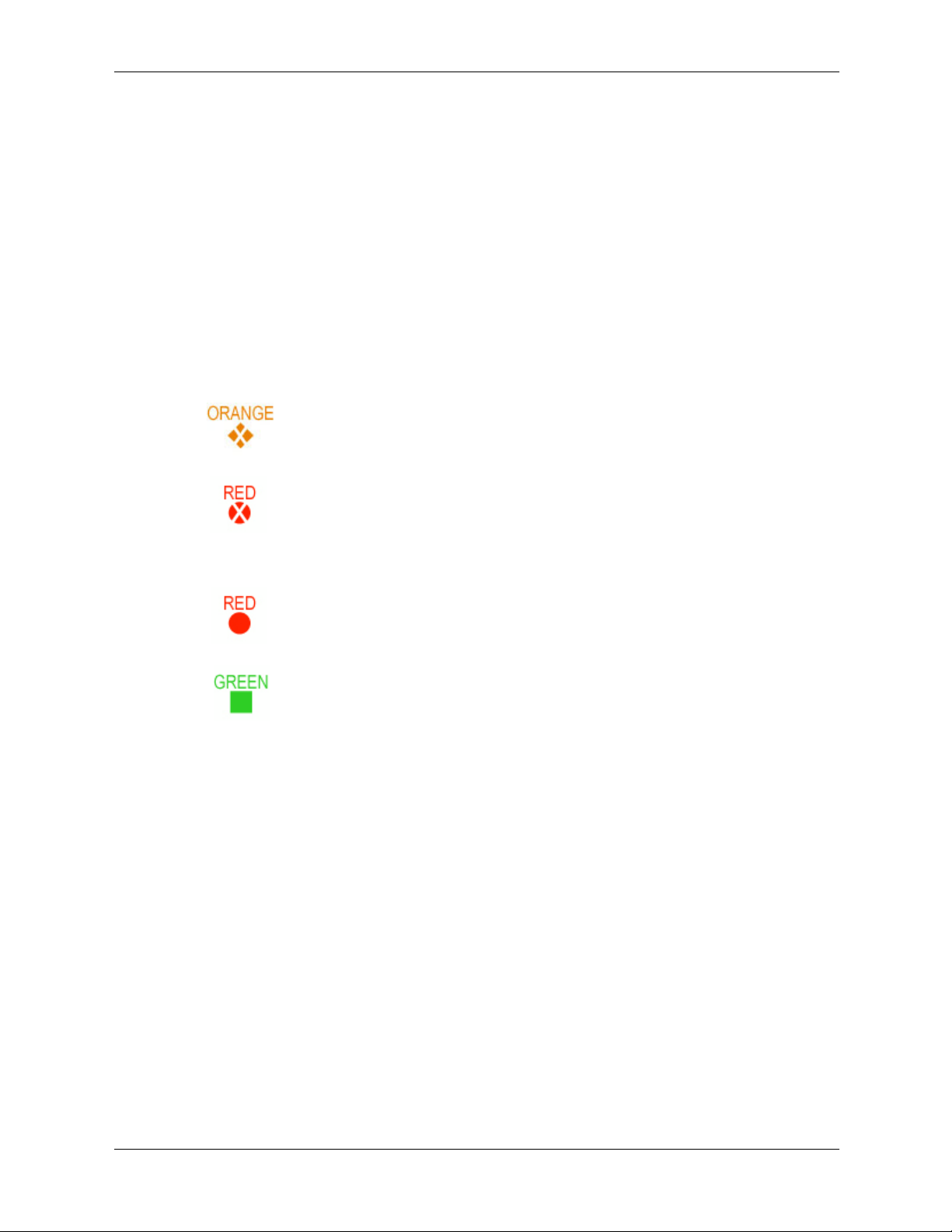
diagnostic LEDs
The four diagnostic LEDs on the front bezel of the system are used for diagnosing the health of
the system. These LEDs warn of impending hardware failures and allow you to take preventive
action, such as making a system backup or replacing a component before it fails. These
diagnostic LEDs are labeled 1, 2, 3 and 4.
The location of red LEDs can be used to identify the category of the fault or warning. For
example, if LED one is red, there is a problem with memory. However, if LEDs one and two are
both red, there is a problem with the system processor.
If the diagnostic LEDs indicates an error, check the SEL (page D-4) for a more detailed
explanations of the failure.
The following symbols are used in the LED tables.
■
The System LED indicates the severity of the error:
Troubleshooting
Blinking orange indicates a WARNING.
Blinking red indicates a FAULT.
■
The Diagnostic LEDs provide details about the specific error that has occurred:
Solid red indicates the failing part or sub-system.
Off or solid green diagnostic LEDs provide additional details about the
failure.
technical reference guide 4–7
Page 92

Troubleshooting
The faults and warnings fall into several general categories.
LED1 LED2 LED3 LED4 Category
Memory 3
Firmware 6
System Board 7
Fan None
e-buzzer
Beeps
Processor 1
BMC 7
Temperature None
Power Supply 2
Unknown None
4–8 technical reference guide
Page 93

Warnings
The following tables provide additional information about each specific warning associated with
the various possible LED lighting sequences when the system LED is orange.
System
LED LED1 LED2 LED3 LED4 Problem Solution
Unknown Warnings
Unknown warning. View the SEL for additional
information (page D-4). For
further assistance, contact
your HP Support Engineer.
Memory Warnings
Troubleshooting
System Board Warnings
Fan Warnings
Mismatched memory
pairs.
Memory thermal load
order.
Bad SPD information
(can't detect type).
Battery voltage low. Replace the system board
Fan 2 (bottom) is not
functioning properly
Fan 1 (top) is not
functioning properly
Use the memory sequence
diagram in “Installing
Memory Modules” on
page 2-11.
Use the memory sequence
diagram in “Installing
Memory Modules” on
page 2-11.
View the SEL for additional
information (page D-4). For
further assistance, contact
your HP Support Engineer.
battery.
Replace the fan that is not
functioning.
If the processor fan has
failed, you must replace the
CPU.
technical reference guide 4–9
Page 94

Troubleshooting
System
LED LED1 LED2 LED3 LED4 Problem Solution
Processor Warnings
Temperature Warnings
Video Warnings
Power Supply Errors
Processor temperature
exceeds limit.
If the processor fan has
failed, you must replace the
CPU.
External air
temperature too high.
Make sure nothing is
blocking the system’s
airflow and locate your
system in an
air-conditioned room.
No video adapter
present.
Install a video adapter. See
the installation instructions
shipped with the video
adapter.
Power supply fault. Replace the power supply.
4–10 technical reference guide
Page 95

Faults
The following tables provide additional information about each specific fault associated with the
various possible LED lighting sequences when the system LED is red.
System
LED LED1 LED2 LED3 LED4 Problem Solution
Unknown Faults
Unknown fault. View the SEL for additional
information (page D-4). For
further assistance, contact
your HP Support Engineer.
Memory Faults
Troubleshooting
Firmware Faults
Mismatched memory
pairs.
Uncorrectable memory
error.
No memory installed. Install memory.
Bad memory. One or
more DIMMs are bad
or not seated properly.
System firmware hang. View the SEL for additional
Use the memory sequence
diagram in “Installing
Memory Modules” on
page 2-11.
Replace memory.
Reseat the DIMMs. If the
error persists, replace them.
information (page D-4). For
further assistance, contact
your HP Support Engineer.
System Board Faults
VRM overvoltage. View the SEL for additional
information (page D-4). For
further assistance, contact
your HP Support Engineer.
technical reference guide 4–11
Page 96
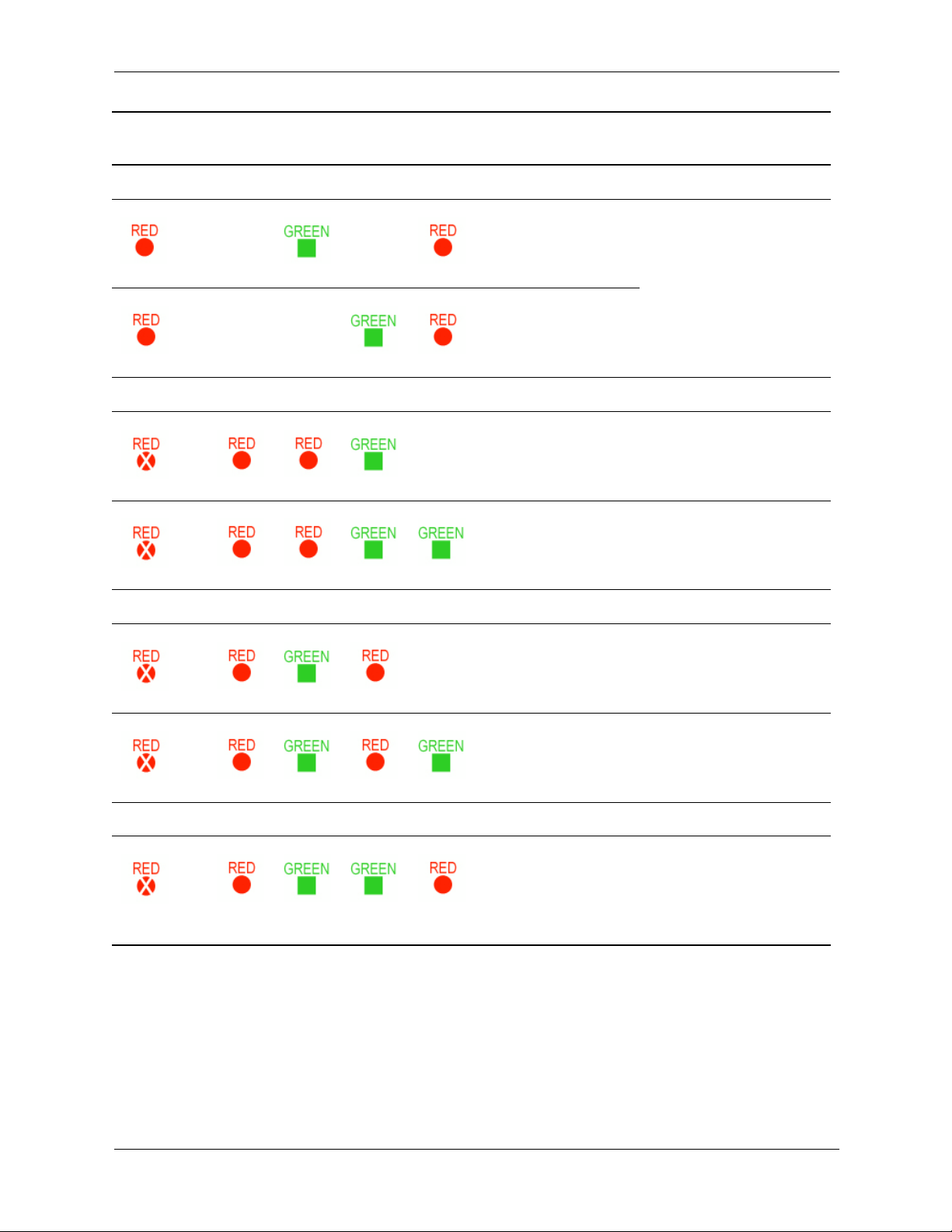
Troubleshooting
System
LED LED1 LED2 LED3 LED4 Problem Solution
Fan Faults
Processor Faults
BMC Faults
Fan 2 (bottom) is not
functioning properly.
Fan 1 (top) is not
functioning properly.
Processor temperature
exceeds limit.
No processor detected.
BMC firmware is
damaged.
Replace the fan that is not
functioning.
If the processor fan has
failed, you must replace the
CPU.
If the processor fan has
failed, you must replace the
CPU.
Replace the CPU.
Reflash the system firmware.
Motherboard FRU
Replace the system board.
inventory device
inaccessible.
Temperature Faults
External air
temperature too high.
Make sure nothing is
blocking the system’s
airflow and locate your
system in an
air-conditioned room.
4–12 technical reference guide
Page 97
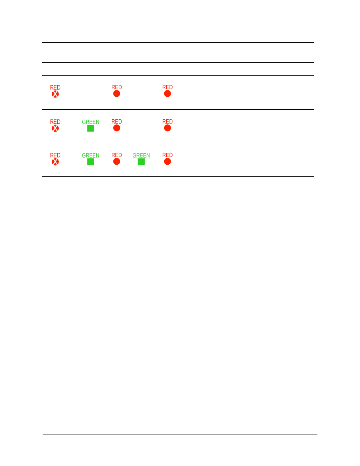
System
LED LED1 LED2 LED3 LED4 Problem Solution
Power Supply Errors
Troubleshooting
VRM or power pod
fault.
View the SEL for additional
information (page D-4). For
further assistance, contact
your HP Support Engineer.
Power Supply fault. Replace the power supply.
12V out of range.
technical reference guide 4–13
Page 98

Troubleshooting
monitor troubleshooting
It is normal for the display to remain blank for a minute or longer during system boot-up.
To access the offline diagnostic tools when your monitor is not working, direct the system output
to a console device for troubleshooting:
1. With the workstation turned off, connect a 9-pin to 9-pin serial cable (HP F1044-80002) to
Serial Port 1 on the rear panel of the workstation, and to a laptop or other device with
terminal emulation software.
2. Configure the terminal emulation software with these settings:
❏
Terminal emulation: VT100+
❏
Wrap lines: Off (unchecked)
❏
Baud rate: 9600
❏
Bits: 8
❏
Parity: None
❏
Stop Bits: 1 (one)
❏
Flow Control: XON/XOFF
NOTE: The default terminal emulation type is VT100+. The default baud rate is 9600. These
setting can be changed from the EFI
Boot Options Maintenance Menu
.
3. Using the terminal emulation software, connect to the workstation with a direct connection.
4. Turn on the workstation and follow the instructions in Running Diagnostic Software Tools,
page 4-15.
4–14 technical reference guide
Page 99

running diagnostic software tools
This section includes information on the following diagnostic tools for the Workstation zx2000:
■
HP e-DiagTools hardware diagnostics, page 4-15
■
Additional diagnostics tools for HP-UX, page 4-18
Before you run the HP diagnostic software, note any e-buzzer and LED error messages. They
give you an indication of the Field Replaceable Unit (FRU) to replace.
hp e-diagtools hardware diagnostics
Your system came with an HP IPF Offline Diagnostics and Utilities CD with HP e-DiagTools
Hardware Diagnostics. These tools may be used to diagnose hardware-related problems on your
HP system.
Run e-DiagTools before contacting HP for Warranty service. This is to obtain information that
will be requested by a Support Agent.
With this utility you can:
■
Check the hardware configuration and verify that it is functioning correctly.
■
Test individual hardware components.
Troubleshooting
■
Diagnose hardware-related problems.
■
Obtain a complete hardware configuration.
■
Provide precise information to an HP support agent so they can solve problems quickly and
effectively.
HP e-DiagTools provides a user-friendly interface to the Offline Diagnostics Environment
(ODE), that enables you to troubleshoot a system that is running without an OS or cannot be
tested using the online tools. ODE can also be run separately using a command line interface,
which allows the user to select specific tests and/or utilities to execute on a specific hardware
module.
technical reference guide 4–15
Page 100

Troubleshooting
starting hp e-diagtools
1. Insert the HP IPF Offline Diagnostics and Utilities CD in the CD or DVD drive.
2. Restart the system.
3. Select the CD/DVD boot option from the EFI startup menu.
NOTE: If you are unable to boot from your CD/DVD drive, restart your system and check the
boot options from the
configured to boot from the CD/DVD drive.
4. If you are not familiar with e-DiagTools, review the documentation. From the main menu:
Boot Options Maintenance Menu
to ensure that your system is
a. Select
View Release Notes and Documentation Menu
documentation.
b. Select
View e-DiagTools Info
5. If you are already familiar with e-DiagTools, select
main menu.
producing a support ticket
To produce a complete record of your system’s configuration and test results, you will need to
create a Support Ticket. This is a simple text file that contains essential information and is
designed to assist your local or HP Support Agent.
To produce a Support Ticket, from the
1. Start e-DiagTools and select
2. Select
3. Select
4. After the test is complete:
2 - Run e-DiagTools Basic System Test (BST)
your system if you have not already done so.
e-DiagTools scans your system. The Configuration Description will display on the screen
when the configuration detection phase is complete
2 - Continue Test
❏
To view the Support Ticket, press 4. (Use the arrow keys to scroll.) Have the support
ticket the screen when you contact customer support.
to view a list of available
to open the overview document.
Run e-DiagTools for IPF
Welcome to e-DiagTools
Run e-DiagTools for IPF
to run the rest of the basic diagnostics test.
from the main menu.
Menu:
to run the basic diagnostics on
from the
❏
To exit the Support Ticket tool, press 3.
4–16 technical reference guide
 Loading...