

Page 1

Getting Started Guide
hp workstation zx2000
Document Part Number: A7844-90050
July 2004
This guide provides an overview of the system front and rear panel
connectors, instructions on how to set up and configure your system,
and troubleshooting tips. The appendix includes regulatory notices.
Page 2

© 2004 Hewlett-Packard Company
Microsoft
trademarks of Microsoft Corporation in the U.S. and other countries.
Intel® and Itanium® are registered trademarks of Intel Corporation in the U.S.
and other countries.
All other product names mentioned herein may be trademarks of their respective
companies.
Hewlett-Packard Company shall not be liable for technical or editorial errors or
omissions contained herein or for incidental or consequential damages in
connection with the furnishing, performance, or use of this material. The
information in this document is provided “as is” without warranty of any kind,
including, but not limited to, the implied warranties of merchantability and
fitness for a particular purpose, and is subject to change without notice. The
warranties for HP products are set forth in the express limited warranty
statements accompanying such products. Nothing herein should be construed as
constituting an additional warranty.
This document contains proprietary information that is protected by copyright.
No part of this document may be photocopied, reproduced, or translated to
another language without the prior written consent of Hewlett-Packard
Company.
Getting Started Guide
hp workstation zx2000
First Edition (July 2004)
Document Part Number: A7844-90050
®, Windows®, Windows 2000®, and Windows XP® are registered
WARNING: Text set off in this manner indicates that failure to follow
Å
directions could result in bodily harm or loss of life.
CAUTION: Text set off in this manner indicates that failure to follow
Ä
directions could result in damage to equipment or loss of information.
Page 3

Important Safety Warnings
WARNING: Avoiding Electrical Shocks. To avoid electrical shock, do not
Å
open the power supplies. There are no user-serviceable parts inside.
To avoid electrical shock and harm to your eyes by laser light, do not
open the DVD laser module. The laser module should be serviced by
service personnel only. Do not attempt to make any adjustment to the laser
unit. Refer to the label on the DVD for power requirements and
wavelength. This product is a class I laser product.
WARNING: Removing and Replacing the Cover. For your safety, never
Å
remove the system side cover without first disconnecting the power cord
from the power outlet and removing any connection to a
telecommunications network. If a Power Protection Device is fitted to your
system, you must shut down your computer using its on/off switch, then
remove the power cord before removing the system’s side cover. Remove
the Power Protection Device cables before any servicing operation. Always
replace the side cover before switching the system on again.
WARNING: Battery Safety Information. There is a danger of explosion if
Å
the battery is incorrectly installed. For your safety, never attempt to
recharge, disassemble, or burn an old battery. Replace the battery with
the same or equivalent type, as recommended by the manufacturer.
The battery in this system is a lithium battery that does not contain any
heavy metals. However, to protect the environment, do not dispose of
batteries in household waste. Return used batteries either to the shop from
which you bought them, to the dealer from whom you purchased your
system, or to HP so that they can either be recycled or disposed of in the
correct way. Returned batteries will be accepted free of charge.
WARNING: Avoiding Burn Injuries. Some parts inside the computer will
Å
be hot. Wait approximately three to five minutes for them to cool down
before touching them.
Page 4

CAUTION: Avoiding Static Electricity. Static electricity can damage
Ä
electronic components. Turn OFF all equipment before installing an
accessory card. Don’t let your clothes touch any accessory card. To
equalize the static electricity when replacing an accessory card, rest the
accessory card bag on top of the system unit while you are removing the
card from the bag. Handle the card as little as possible and with care.
CAUTION: Information on Ergonomic Issues. It is strongly recommended
Ä
that you read the ergonomics information, available in the “Working In
Comfort” section of this manual, before using your system. You can access
more extensive ergonomics information at: www.hp.com/ergo
NOTE: Recycling Your System. HP has a strong commitment toward
the environment. Your HP system has been designed to respect the
environment as much as possible. HP can also take back your old
system for recycling when it reaches the end of its useful life. HP has
a product take-back program in several countries. The collected
equipment is sent to an HP recycling facilities in Europe or the U.S.A.
As many parts as possible are reused. The remainder is recycled.
Special care is taken for batteries and other potential toxic substances,
these are reduced into non-harmful components through special
chemical processes. If you require more details about the HP product
take-back program, contact your local dealer or your nearest HP Sales
Office.
Page 5

Contents
1 Setting Up and Using Your System
System Description . . . . . . . . . . . . . . . . . . . . . . . . . . . . . . . . . . . . . . . . . . . . . . . . . . . . 1–2
Front Panel . . . . . . . . . . . . . . . . . . . . . . . . . . . . . . . . . . . . . . . . . . . . . . . . . . . . . . . 1–2
Rear Panel. . . . . . . . . . . . . . . . . . . . . . . . . . . . . . . . . . . . . . . . . . . . . . . . . . . . . . . . 1–4
Setting Up Your System . . . . . . . . . . . . . . . . . . . . . . . . . . . . . . . . . . . . . . . . . . . . . . . . 1–5
Tools . . . . . . . . . . . . . . . . . . . . . . . . . . . . . . . . . . . . . . . . . . . . . . . . . . . . . . . . . . . . 1–5
Connecting Devices . . . . . . . . . . . . . . . . . . . . . . . . . . . . . . . . . . . . . . . . . . . . . . . . 1–7
Starting and Stopping Your System . . . . . . . . . . . . . . . . . . . . . . . . . . . . . . . . . . . . . . . 1–9
Starting Your System . . . . . . . . . . . . . . . . . . . . . . . . . . . . . . . . . . . . . . . . . . . . . . . 1–9
Turning Off Your System. . . . . . . . . . . . . . . . . . . . . . . . . . . . . . . . . . . . . . . . . . . 1–11
Installing Hardware Components . . . . . . . . . . . . . . . . . . . . . . . . . . . . . . . . . . . . . . . . 1–12
Firmware and Drivers . . . . . . . . . . . . . . . . . . . . . . . . . . . . . . . . . . . . . . . . . . . . . . 1–14
Configuring Your System . . . . . . . . . . . . . . . . . . . . . . . . . . . . . . . . . . . . . . . . . . . . . . 1–15
Extensible Firmware Interface (EFI) . . . . . . . . . . . . . . . . . . . . . . . . . . . . . . . . . . 1–15
Baseboard Management Controller (BMC) . . . . . . . . . . . . . . . . . . . . . . . . . . . . . 1–22
2Troubleshooting
Your System Does Not Start Properly . . . . . . . . . . . . . . . . . . . . . . . . . . . . . . . . . . 2–2
You Find a Hardware Problem . . . . . . . . . . . . . . . . . . . . . . . . . . . . . . . . . . . . . . . . 2–3
Mouse Problems . . . . . . . . . . . . . . . . . . . . . . . . . . . . . . . . . . . . . . . . . . . . . . . . . . . 2–4
Troubleshooting with the System LEDs. . . . . . . . . . . . . . . . . . . . . . . . . . . . . . . . . 2–6
Troubleshooting with the e-buzzer . . . . . . . . . . . . . . . . . . . . . . . . . . . . . . . . . . . . . 2–9
Software Diagnostics Tools. . . . . . . . . . . . . . . . . . . . . . . . . . . . . . . . . . . . . . . . . . . . . 2–11
HP e-DiagTools Hardware Diagnostics . . . . . . . . . . . . . . . . . . . . . . . . . . . . . . . . 2–11
Additional Diagnostics Tools for HP-UX . . . . . . . . . . . . . . . . . . . . . . . . . . . . . . 2–14
Recovering the OS. . . . . . . . . . . . . . . . . . . . . . . . . . . . . . . . . . . . . . . . . . . . . . . . . . . . 2–15
Getting Started Guide v
Page 6

Contents
Where to Get Help. . . . . . . . . . . . . . . . . . . . . . . . . . . . . . . . . . . . . . . . . . . . . . . . . . . . 2–16
Information To Collect Before You Contact Support . . . . . . . . . . . . . . . . . . . . . 2–16
Online Support . . . . . . . . . . . . . . . . . . . . . . . . . . . . . . . . . . . . . . . . . . . . . . . . . . . 2–17
Phone Support. . . . . . . . . . . . . . . . . . . . . . . . . . . . . . . . . . . . . . . . . . . . . . . . . . . . 2–17
Additional Documentation . . . . . . . . . . . . . . . . . . . . . . . . . . . . . . . . . . . . . . . . . . 2–18
A Regulatory Information
Federal Communications Commission Radio Frequency Interference Statement
(for USA only). . . . . . . . . . . . . . . . . . . . . . . . . . . . . . . . . . . . . . . . . . . . . . . . . . . . . . . . 2–3
Notice for Canada . . . . . . . . . . . . . . . . . . . . . . . . . . . . . . . . . . . . . . . . . . . . . . . . . . . . . 2–3
Safety Warning for the USA and Canada . . . . . . . . . . . . . . . . . . . . . . . . . . . . . . . . . . . 2–3
Notice for France. . . . . . . . . . . . . . . . . . . . . . . . . . . . . . . . . . . . . . . . . . . . . . . . . . . . . . 2–4
Notice for the Netherlands . . . . . . . . . . . . . . . . . . . . . . . . . . . . . . . . . . . . . . . . . . . . . . 2–4
Notice for Germany. . . . . . . . . . . . . . . . . . . . . . . . . . . . . . . . . . . . . . . . . . . . . . . . . . . . 2–4
Noise Declaration for Germany . . . . . . . . . . . . . . . . . . . . . . . . . . . . . . . . . . . . . . . . . . 2–5
Notice for Japan (Class A) . . . . . . . . . . . . . . . . . . . . . . . . . . . . . . . . . . . . . . . . . . . . . . 2–5
Notice for Korea . . . . . . . . . . . . . . . . . . . . . . . . . . . . . . . . . . . . . . . . . . . . . . . . . . . . . . 2–5
Notice for Taiwan . . . . . . . . . . . . . . . . . . . . . . . . . . . . . . . . . . . . . . . . . . . . . . . . . . . . . 2–5
Index
vi Getting Started Guide
Page 7

1
setting up and using your system
This section provides:
■ description of front and rear panel
■ setup instructions
■ system configuration instructions
■ troubleshooting tips
Getting Started Guide 1–1
Page 8

Setting Up and Using Your System
system description
The zx2000 workstation is available in tower and rack-mount
configurations.
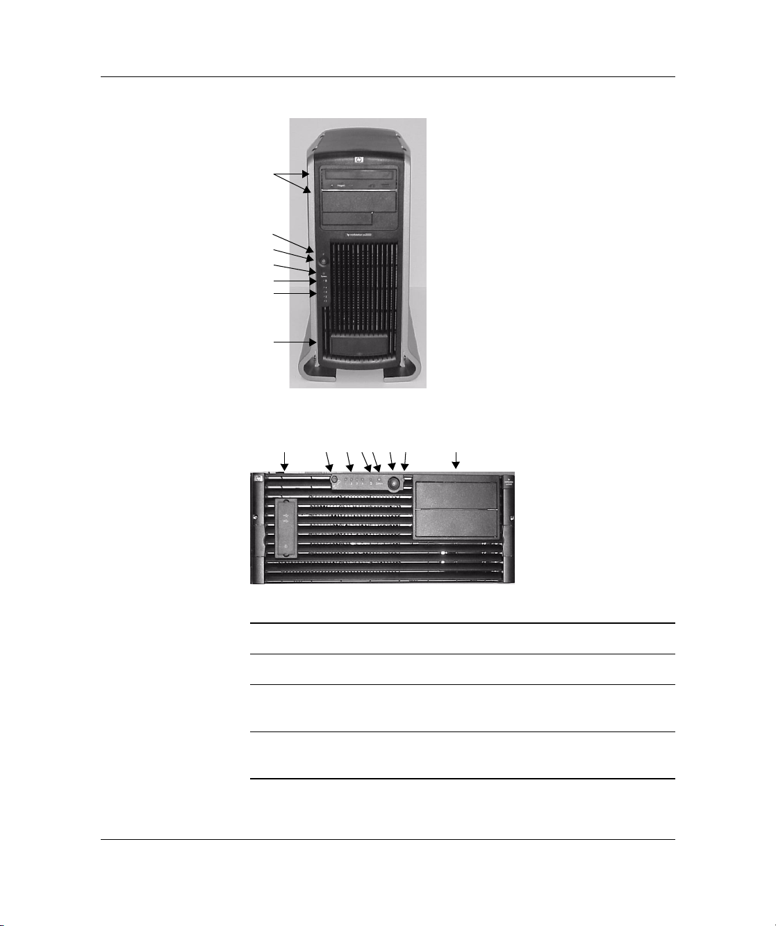
front panel
The hp workstation zx2000 front panel has the following features:
■ Two front-access USB connectors.
■ Two front-access optical drive bays.
■ Power button to turn system on or off.
■ Power LED: green when the power is on or the power button is
pushed in. If the power is on and the button is pushed in, the light
will stay on even after the system is powered down. When the
button is released, the green light turns off.
■ Activity LED: indicates whether the system is accessing any of
the hard drives or optical drives (IDE or SCSI). If the LED is:
❏ off, the system is off, or the system is not accessing internal
drives
❏ blinking green, the system is accessing an internal drive
NOTE: The Activity LED is only active on systems purchased after
March 2003.
NOTE: The Activity LED automatically communicates with IDE
HDD or optical drives. To communicate with SCSI drives, a SCSI
LED activity cable must connect the SCSI card and the system board.
■ System and Diagnostic LEDs provide information about system
errors.
■ Locator Button and LED (rack-mount configuration only)
identifies the rack position of the workstation.
1–2 Getting Started Guide
Page 9
1
2
3
4
5
6
7
Front Panel, Tower Configuration
Setting Up and Using Your System
12345678
Front Panel, Rack Configuration
1 Optical drive bays 5 Activity LED
2 Power LED 6 Diagnostic LEDs 1-4
3 Power button 7 Front-access USB connectors
(behind door)
4 System LED 8 Locator LED and Button
(rack-mounted system only)
Getting Started Guide 1–3
Page 10
Setting Up and Using Your System
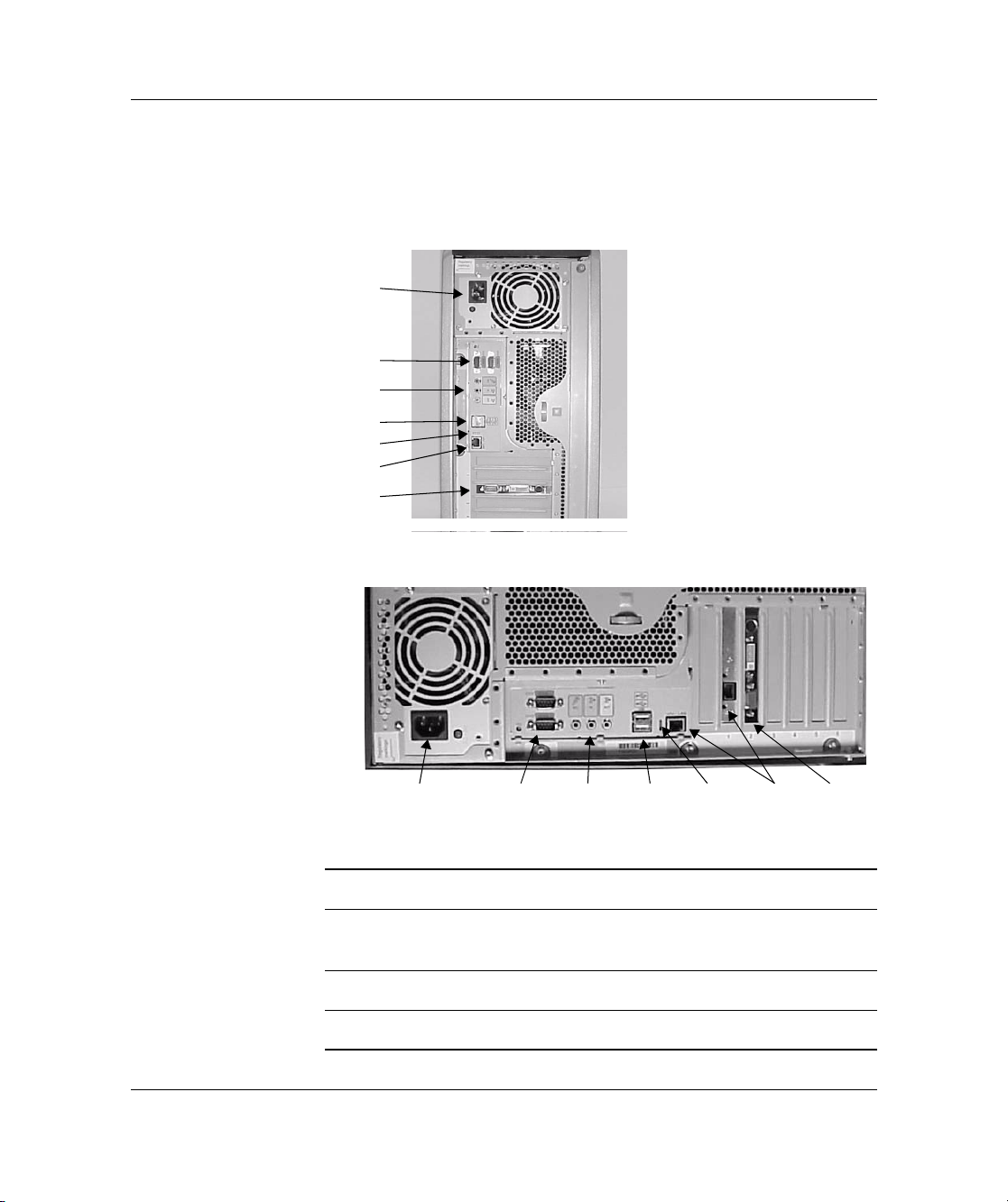
rear panel
The connectors are shaped to go in one way only. Refer to the label on
the back of the workstation.
Rear Panel Connectors, Tower Configuration
1
2
3
4
5
6
7
12 4
Rear Panel Connectors, Rack-mounted Configuration
1 Power 5 LAN LEDs
2 Serial ports 6 Built-in LAN and optional
3 Audio
4 USB
1–4 Getting Started Guide
(headphone, microphone)
37
second LAN ports
7 Monitor port(s) on graphics card
5
6
Page 11

setting up your system
WARNING: If you have any doubt that you can lift the system or monitor
Å
safely, do not try to move them without help.
1. Check the materials list shipped with your system to verify that
you have all of the components.
2. Position the system so that its rear connectors are easily
accessible:
❏ If the system is a tower configuration, place the system in an
area with easily accessible power outlets and enough space
for the keyboard, mouse, and any other accessories.
❏ If the system is to be rack-mounted, refer to the mounting
instructions provided with your system.
tools
You do not need any tools to set up your system. However, if you plan
to install additional hardware components, you will need:
Setting Up and Using Your System
■ Flat blade screwdriver
■ T-15 Torx driver
■ Special processor tool (provided with processor)
■ Static-free mat
■ Static strap
WARNING: Metallic particulates can be especially harmful around electronic
Å
equipment. This type of contamination may enter the data center environment
from a variety of sources, including, but not limited to, raised floor tiles, worn
air conditioning parts, heating ducts, rotor brushes in vacuum cleaners or
printer component wear. Because metallic particulates conduct electricity, they
have an increased potential for creating short circuits in electronic equipment.
This problem is exaggerated by the increasingly dense circuitry of any
electronic equipment.
Over time, very fine whiskers of pure metal can form on electroplated zinc,
cadmium, or tin surfaces. If these whiskers are disturbed, they may break off
and become airborne, possibly causing failures or operational interruptions. For
Getting Started Guide 1–5
Page 12

Setting Up and Using Your System
over 50 years, the electronics industry has been aware of the relatively rare, but
possible, threat posed by metallic particulate contamination. During recent
years, a growing concern has developed in computer rooms where these
conductive contaminants are formed on the bottom of some raised floor tiles.
Although this problem is relatively rare, it may be an issue within your computer
room. Since metallic contamination can cause permanent or intermittent failures
on your electronic equipment, Hewlett-Packard strongly recommends that your
site be evaluated for metallic particulate contamination before installation of
electronic equipment.
1–6 Getting Started Guide
Page 13

connecting devices
Before connecting any cords or cables to your system, please read the
Warning Notices in the front of this manual.
power, keyboard and mouse
To connect the power, keyboard and mouse:
1. Connect the power cords to the rear of the monitor and the
computer.
2. Connect both power cords to a grounded outlet (for tower
systems) or to a power distribution unit (PDU) on the rack (for
racked systems).
3. Connect the keyboard and mouse. This system uses Standard 104
keyboard with a USB connector. Plug them into the USB ports on
the back of the system. (Ports are labelled.)
WARNING: For your safety always connect equipment to a grounded wall
Å
outlet. Always use a power cord with a properly grounded plug, such as the
one provided with the equipment, or one in compliance with your national
safety standards. To ensure that the equipment can be disconnected from the
power by removing the power cord from the outlet, the equipment must be
located close to an easily accessible power outlet.
Setting Up and Using Your System
Getting Started Guide 1–7
Page 14

Setting Up and Using Your System
graphics cards
The zx2000 workstation is available with a range of graphics cards.
■ Graphics cards may include an 15-pin connector, an 18-pin
■ Some video cards are pre-installed in the system, whereas others
■ For more detailed information about your graphics card, see the
■
connector, or both. Only one connecting cable is needed for each
monitor.
are packaged separately and shipped with the system. If your
workstation did not ship with a pre-installed graphics card, you
must install the card and load the drivers. Refer to the
documentation included with your graphics card for instructions.
manufacturer’s web site:
❏ AT I : www.ati.com
❏
NVIDIA: www.NVIDIA.com
For a complete and current list of supported cards with supported
display resolutions and frequencies, see the hp zx2000 Technical
Reference Guide.
❏ Frequencies of 85Hz and higher provide flicker-free viewing.
❏ If the monitor you select is DDC-2B or DDC-2B+ compliant,
the graphics card will automatically limit itself to those
resolutions and frequencies supported by that monitor. In this
case, you do not need to use the tables to select your monitor.
CAUTION: To prevent possible damage to your monitor, make sure you select
Ä
a monitor that supports the resolutions and frequencies you wish to use.
1–8 Getting Started Guide
Page 15

starting and stopping your system
The zx2000 workstations come in several different configurations.
Please pay careful attention to the directions below and choose the
options that match the OS and packaging that you purchased.
starting your system
To start your system:
1. Turn on the monitor before you start your system.
2. Press the power button on the front panel. The system starts.
During system startup, the display may remain blank for up to
one minute. This is normal. The following should occur:
❏ Power LED turns on
❏ System LED blinks on and off
❏ Diagnostic LEDs 1-4 create scrolling pattern
Setting Up and Using Your System
3. If you are prompted for a password, type it and press
Enter.
The password prompt displays only if you have set a password in
the EFI Boot Manager program. (See “Using the
Security/Password Menu” on page 21.)
Getting Started Guide 1–9
Page 16

Setting Up and Using Your System
initializing your software
The zx2000 can be configured with the Operating System (OS)
pre-installed or packaged separately.
■ If you purchased a system with the OS pre-installed, the
initialization process starts when you start the workstation for the
first time.
The software initialization process takes a few minutes. You can
change the settings after the software has been initialized.
CAUTION: Do NOT switch OFF the system while the software is being
Ä
initialized — this could cause unexpected results.
The initialization process:
❏ Displays the license agreement.
❏ Asks questions about the system.
■ If you purchased a system and the OS is not pre-installed, install
the OS now:
❏ HP-UX: Follow the instructions on the HP-UX CD envelope.
❏ Linux: Follow the instructions on the Linux OS CD
envelope.
❏ Windows: Only available pre-installed.
1–10 Getting Started Guide
Page 17

turning off your system
To turn off the system:
1. Exit all applications.
2. Execute the Shut Down command provided by your OS.
3. When prompted, press the power button on your system.
NOTE: You can also shut down using the power button on the
system. When you press the power button, the OS shuts down and the
power turns off.
Setting Up and Using Your System
Getting Started Guide 1–11
Page 18

Setting Up and Using Your System
installing hardware components
If you purchased an accessory card, a graphics card, or other
hardware components that were not installed in your system at the
factory, you must install those components now.
WARNING: For hardware installation procedures, you must power off the
system and unplug the power cord from the outlet.
NOTE: To maintain FCC/EMI (Electromagnetic Interference)
compliance, replace all covers and make sure all screws are properly
seated after you replace components.
1. If you have already connected and turned on the system, turn off
the system and disconnect all cables from the rear panel.
2. Remove the system access covers.
1–12 Getting Started Guide
Page 19

Setting Up and Using Your System
3. Install the new components. The following diagram shows the
location of internal components.
1 PCI and AGP slots 6 optical drives
2 PCI/AGP retainer arm 7 shipping screws
3 memory 8 fans
4 power supply 9 front-access USB
5 hard drive cage
For detailed instructions on installing hardware components, see
the hp zx2000 Technical Reference Guide.
4. Replace the system access covers.
5. Connect the system.
Getting Started Guide 1–13
Page 20

Setting Up and Using Your System
firmware and drivers
To download the latest drivers and firmware for your system, go to the
“Software and Drivers” section of the HP support site:
www.hp.com/go/bizsupport.
At this site you can also read firmware upgrade instructions and
register to obtain information on new driver availability
automatically.
1–14 Getting Started Guide
Page 21

configuring your system
Two tools are available to configure your system:
■ Extensible Firmware Interface (EFI)
■ Baseboard Management Controller (BMC)
This section provides a brief introduction to these tools. For complete
information, refer to “System Configuration” in the zx2000 Technical
Reference Guide.
extensible firmware interface (efi)
The Extensible Firmware Interface (EFI) is an interface that allows
you to configure the Itanium Processor Family (IPF) firmware.
When you turn on your system and it begins to start up, your system
pauses at the
EFI Boot Manager ver x.xx [xx.xx]
Please select a boot option
boot option screen:
Setting Up and Using Your System
your OS]
[
EFI Shell [Built-in]
Boot option maintenance menu
Security/Password Menu
Use up and down arrows to change option(s).
Use Enter to select an option
NOTE: You have seven seconds to change the boot option before the
system boots to the default OS.
Getting Started Guide 1–15
Page 22

Setting Up and Using Your System
Use the up or down arrow keys to highlight an option, then press
Enter.
■ EFI Shell [Built-in] is a command line interface that allows you
■ Boot Option Maintenance Menu allows you to select the
■ Security/Password Menu lets you add, change and delete
remote access
You can also access the EFI remotely.
1. With the workstation turned off, connect a 9-pin to 9-pin serial
2. Configure the terminal emulation software with these settings:
to operate the EFI commands or create and run automated scripts.
order of the devices from which you want the firmware to attempt
to boot the OS. You can also configure the system to boot from a
configuration file.
system administrator and user passwords.
cable to Serial Port A on the rear panel of the workstation, and to
your remote device.
❏ Baud rate: 9600
❏ Bits: 8
❏ Parity: None
❏ Stop Bits: 1 (one)
❏ Flow Control: XON/XOFF
3. Using the terminal emulation software, connect to the
workstation with a direct connection.
NOTE: The default terminal emulation type is VT100+. This setting
can be changed from the EFI Boot Options Maintenance Menu.
4. Turn on the workstation and follow the steps below to access
the EFI.
1–16 Getting Started Guide
Page 23

using the efi shell
Setting Up and Using Your System
To access the EFI shell:
1. When the EFI boot option screen displays, use the arrow keys to
highlight
EFI Shell, then press Enter.
2. A list of file systems (drives and partitions), and block devices on
hard drives is displayed. For example:
Device mapping table
fs0: Acpi(HWP0002,100)/Pci(1|0)/Scsi(Pun0,Lun0)/HD(Part1,Sig00112233)
blk0: Acpi(HWP0002,0)/Pci(2|0)/Ata(Primary,Master)
blk1: Acpi(HWP0002,100)/Pci(1|0)/Scsi(Pun0,Lun0)
3. The EFI shell first searches for an optional script file named
startup.nsh. If this file is found, it is executed automatically.
If the script does not automatically start an OS or other
application, the shell then waits for commands to be entered at the
command prompt.
Getting Started Guide 1–17
Page 24

Setting Up and Using Your System
4. You can now enter commands.
To run an individual command:
a. Type the command at the shell prompt. For example, to clear
the display on the monitor:
Shell:\> cls
b. Press Enter to execute the command.
◆ Some commands require additional arguments to further
define their action. For example, to display information
about the system memory, you must type the command
name, plus the desired category of information to display:
fs0:\> info mem
When you enter individual commands at the command
◆
prompt, the shell performs variable substitution, then
expands wild cards before the command is executed.
◆ To switch to a different file system, execute the
following, where fsx is the selected file system, as listed
on the screen (see step 2). For example:
Shell> fsx:
You see this prompt:
fs0:\> _
You can also run EFI applications (files ending with
◆
.efi). To list applications in the current file system, run
ls command.
the
1–18 Getting Started Guide
Page 25

Setting Up and Using Your System
The following section provides a list of EFI command categories. For
more information, see the hp zx2000 Technical Reference Guide or
use the EFI shell’s help system.
To access a:
■ List of EFI command classes, execute help at the EFI shell
prompt.
■ Detailed description of a command, execute help and the
command name at the EFI shell prompt. For example:
fs0:\> help date
EFI commands are organized into different classes based on their
functions. The classes include:
■ boot — boot options and disk-related commands
■ configuration — change and retrieve system information
■ device — get device, driver and handle information
■ memory — memory related commands
■ shell — basic shell navigation and customization
■ scripts — EFI shell script commands
Getting Started Guide 1–19
Page 26

Setting Up and Using Your System
using the boot option maintenance menu
This menu allows you to select console output and input devices as
well as various boot options. To:
■ display the help available for the command, select Help
■ return to the main Boot Options Maintenance menu, select Exit
■ highlight an item using the arrow keys, then press Enter
■ save your changes, select Save Settings to NVRAM
The Boot Option Maintenance Menu contains the following
options.
Option Function
Boot from a File
Add a Boot Option
Delete Boot Option(s)
Change Boot Order
Manage BootNext
Setting
Set Auto Boot TimeOut
Select Active Console
Output Devices
Select Active Console
Input Devices
Select Active Standard
Error Devices
Cold Reset
Manually runs a specific application or driver.
Adds items to the EFI boot menu.
Removes options from the EFI boot menu.
Changes the order of boot options. The order in which options are
listed in the EFI boot menu also reflects the order in which the
system attempts to boot.
Selects a boot option to be executed on the next system boot. This
does not change the permanent system boot settings.
Sets the amount of time the system will pause before attempting to
launch the first item in the Boot Options list.
Defines devices to display output from the system console.
Defines devices to provide input to the system console.
Defines the devices that will display error messages from the system
console.
Shuts down and restart the system.
Exit
1–20 Getting Started Guide
Returns to the EFI startup menu.
Page 27

using the security/password menu
You can set administrator and user passwords to provide different
levels of access to the system firmware:
■ The Administrator can access and change all settings in the EFI
Boot Manager program and can run the EFI shell.
■ The User can access basic functions in the EFI Boot Manager.
NOTE: This password limits access to the firmware interface only.
You must create passwords if you want to limit access to the EFI. No
passwords are set at the factory.
This is not the OS password. For information on setting OS
passwords, see your OS user guide.
Security/Password Menu of the EFI lets you change the
The
administrator and user passwords:
1. Select Security/Password Menu.
2. Select either:
Setting Up and Using Your System
❏ Set Administrator Password
❏ Set User Password
3. Select:
❏ Set Administrator Password or Set User Password to
set a new password
❏ Enable/disable Password to specify whether a password
is required
❏ Help for assistance
4. When you are finished, select Exit.
Getting Started Guide 1–21
Page 28

Setting Up and Using Your System
baseboard management controller (bmc)
The Baseboard Management Controller supports the
industry-standard Intelligent Platform Management Interface (IPMI)
specification. This specification describes the management features
that have been built into the system board. These features include:
■ local and remote diagnostics
■ console support
■ configuration management
■ hardware management
■ troubleshooting
For a complete listing of BMC Commands, see the System
Configuration section in the zx2000 Technical Reference Guide.
1–22 Getting Started Guide
Page 29

2
troubleshooting
This chapter contains basic information to help you get your system
up and running in the unlikely event that you experience a problem.
Topics include:
■ Your System Does Not Start Properly
■ You Find a Hardware Problem
❏ Keyboard Problems
❏ Mouse Problems
❏ Graphics and Monitor Problems
■ Troubleshooting with the LED and e-buzzer Codes
■ Software Diagnostics Tools
■ Restoring the OS
■ Where to Get Help
NOTE: If you need technical assistance, call HP at 1-800-593-6631
(USA) or go to
contact hp in your region.
Getting Started Guide 2–1
www.hp.com/country/us/eng/contact_us.html to
Page 30

Troubleshooting
your system does not start properly
The system doesn’t power on.
Make sure... How
The system power cord is properly connected. Connect the power cord to a working power
outlet and to the rear of the system.
There is a buzzing noise.
A beep code when the system starts up means that there is a configuration problem. Many of the
e-buzzer codes relate to the LED diagnostic codes. See section “Using the LEDs and e-buzzer to
Troubleshoot Your System”.
Make sure... How
You correctly identify the e-buzzer error code. Count the number of beeps after the buzzer (refer
to the section “Troubleshooting with the e-buzzer”
on page 2-9).
Contact HP Support (refer to page 2-16).
If you still have a problem, see “Software Diagnostics Tools” on page 2-11.
2–2 Getting Started Guide
Page 31

you find a hardware problem
keyboard problems
The keyboard doesn’t work.
Make sure... How
Troubleshooting
The keyboard cable is correctly connected and
the mouse driver is loaded.
The keyboard is free of debris. Check all keys are at the same height, and
The keyboard itself is not defective. Either replace the keyboard by a known
You are using the correct driver. Refer to your
OS documentation.
You are using the latest firmware. Download the latest firmware from:
Plug the cable into the correct connector on the
back of the system. Ports are labelled for easy
matching.
Reboot the workstation to load the mouse
driver on startup.
none are stuck down.
working unit or try the keyboard with another
system.
Download the latest driver from:
www.hp.com/go/bizsupport
www.hp.com/go/bizsupport
Getting Started Guide 2–3
Page 32

Troubleshooting
mouse problems
The mouse doesn’t work.
Make sure... How
The mouse cable is correctly connected. Plug the cable into a USB port on the back of
the system. Ports are labeled for easy
identification.
You are using the correct driver. If you are using
the HP enhanced mouse, ensure that the correct
driver is installed.
Linux preloaded systems.
This driver is provided with all
Download the latest driver from:
www.hp.com/go/bizsupport
You are using the latest firmware Download the latest firmware from:
www.hp.com/go/bizsupport
The mouse is clean. Clean the mouse ball as shown below.
The mouse itself is not defective. Replace the mouse with unit that is known to
work or try the mouse with another system.
If the system starts but you still have a problem, see “Software Diagnostics Tools” on page 2-11.
2–4 Getting Started Guide
Page 33

graphics and monitor problems
The monitor doesn’t work.
The system’s power indicator light works but the monitor remains blank
Make sure... How
Troubleshooting
The monitor power cord is correctly
connected.
The monitor is switched ON (LED is on). Refer to the monitor manual for an
The graphics card is installed and the monitor
(video) cable is correctly connected.
The monitor’s brightness and contrast settings
are correctly set.
The EFI console output settings are correct. Check and correct the settings using the EFI
If the system starts and you still have a problem, see “Software Diagnostics Tools” on
page 2-11.
Ensure the power cord is plugged into a
working grounded power outlet and into the
monitor.
explanation of the LED signals.
Ensure the monitor (video) cable is properly
connected to both the system and the
monitor. Ensure the cable is connected to the
graphics card’s connector.
Check the settings using the on-screen
display or controls on the front of the
monitor.
Boot Options Maintenance Menu. For
instructions, see page 1-20.
Getting Started Guide 2–5
Page 34

Troubleshooting
troubleshooting with the system LEDs
Several LEDs are on the front panel of the system. The following
sections describe their functions.
power and system LEDs
The Power and System LEDs indicate the state of the system.
Power LED System LED State
Off Off Off
On (green) Solid green Running
On (green) Off Booting
On (green) Blinking orange (1/sec.) Attention
On (green) Blinking red (2/sec.) Fault
activity LED
The Activity LED indicates the state of disk and drive activity on the
system.
NOTE: The Activity LED is only active on systems purchased after
March 2003.
NOTE: The Activity LED automatically communicates with IDE
HDD or optical drives. To communicate with SCSI drives, a SCSI
LED activity cable must connect the SCSI card and the system board.
Activity LED State
Off Off or no current disk/drive
activity
Blinking (green) Disk drive being accessed
2–6 Getting Started Guide
Page 35

locator LED and button (rack-mounted systems only)
You may find it difficult to identify a specific computer requiring
maintenance if you have several similar systems in a rack. The locator
LED is designed to help identify the system in a rack.
To activate the locator LED, press the locator button on the front bezel
of the system.
NOTE: The locator LED can also be lit using BMC commands. See
the HP zx2000 Technical Reference Guide.
When the locator button is pressed in, the locator LED begins to flash
blue at a frequency of one blink per second both on the front of the
system and the back, making it easy to locate the system.
diagnostic LEDs
The four diagnostic LEDs located on the front bezel of your system
are labeled one through four. Chapter 4 of the hp zx2000 Technical
Reference Guide provides a table with a list of faults associated with
the various possible LED lighting sequences.
Troubleshooting
Getting Started Guide 2–7
Page 36

Troubleshooting
lan LEDs (back panel)
The four LAN LEDs on the back panel of the system indicate LAN
activity.
LAN LED Location Color State
1. Gbit Tower: Right Off No 1000 Mbps link
Rack-mounted: Top Green Port linked at 1000 Mbps
2. 100mb Tower: 2nd from right Off No 100 Mbps link
Rack-mounted: 2nd from top Green Port linked at 100 Mbps
3. Link Tower: 2nd from left Off No LAN connection
Rack-mounted: 2nd from bottom Green Link connectivity on LAN port
4. Activity Tower: Left Off No LAN activity
Rack-mounted: Bottom Green Flashing or solid green LED indicates
activity on LAN port
2–8 Getting Started Guide
Page 37

troubleshooting with the e-buzzer
When your system starts up, the system firmware performs pre-boot
diagnostics to test your hardware configuration for any problems. If a
problem is detected during pre-boot, the e-buzzer emits audible beeps
and an encoded error message.
The e-buzzer emits a different number of beeps for each type of error.
More detailed information is provided by the system LEDs.
Number
of Beeps Component Description
1 Processor Processor absent, not correctly
connected. Reseat or replace processor.
2 Power Supply Power supply failure. Replace power
supply.
3 Memory No memory, bad memory modules or
incompatible memory module. Check
memory module loading order. Reseat or
replace memory modules.
Troubleshooting
4 Graphics Card Graphics card problem. Reseat or
replace the graphics card.
5 PCI Card PCI card problem. Reseat or replace the
PCI card.
6 General Failure Possible problems include: System board
failure, CPU connection problem,
CPU failure, CPU power failure.
See the hp zx2000 Technical Reference
Guide for additional details and
recommendations.
7 System Board Defective system board. Contact support.
Getting Started Guide 2–9
Page 38

Troubleshooting
NOTE: If you miss the beep code, send the signal again. Press the
power supply button for 3 seconds, then release it once the sound
begins.
The e-buzzer also emits an electronic signal that can be sent through a
telephone line to an authorized help desk or HP Support. This signal
can be decoded by help desk equipment to identify the workstation
model and serial number as well as details about any faults. To send
this signal to HP Support, hold your telephone next to the front bezel
when the system is booting.
2–10 Getting Started Guide
Page 39

software diagnostics tools
This section includes information on the following diagnostic tools:
■ HP e-DiagTools Hardware Diagnostics
■ Additional Diagnostics Tools for HP-UX
Before you run the HP diagnostic software, note any e-buzzer and
LED errors.
hp e-diagtools hardware diagnostics
Your system came with an HP IPF Offline Diagnostics and Utilities
CD with HP e-DiagTools Hardware Diagnostics. These tools can be
used to diagnose hardware-related problems on your HP system.
Run e-DiagTools before contacting HP for Warranty service. This is
to obtain information that will be requested by a support agent.
With this utility you can:
■ Check the hardware configuration and verify that it is functioning
correctly.
Troubleshooting
■ Test individual hardware components.
■ Diagnose hardware-related problems.
■ Obtain a complete hardware configuration.
■ Provide precise information to an HP support agent so they can
solve problems quickly and effectively.
HP e-DiagTools provides a user-friendly interface to the Offline
Diagnostics Environment (ODE), that enables you to troubleshoot a
system that is running without an OS or cannot be tested using the
online tools. ODE can also be run separately using a command line
interface, which allows the user to select specific tests and/or utilities
to execute on a specific hardware module. See the hp zx2000
Technical Reference Guide for more information.
Getting Started Guide 2–11
Page 40

Troubleshooting
starting hp e-diagtools
1. Insert the HP IPF Offline Diagnostics and Utilities CD in the CD
or DVD drive.
2. Restart the system.
3. Select the CD/DVD boot option from the EFI startup menu.
NOTE: If you are unable to boot from your CD/DVD drive, restart
your system and check the boot options from the
Maintenance Menu
to ensure that your system is configured to
boot from the CD/DVD drive.
4. If you are not familiar with e-DiagTools, review the
documentation. From the main menu:
Boot Options
a. Select
b. Select
View Release Notes and Documentation
Menu
to view a list of available documentation.
View e-DiagTools Info to open the overview
document.
5. If you are already familiar with e-DiagTools, select
e-DiagTools for IPF
from the main menu.
Run
2–12 Getting Started Guide
Page 41

Troubleshooting
producing a support ticket
To produce a complete record of your system’s configuration and test
results, you will need to create a Support Ticket. This is a simple text
file that contains essential information and is designed to assist your
local or HP Support Agent.
To produce a Support Ticket, from the
Welcome to e-DiagTools
Menu:
1. Start e-DiagTools and select
Run eDiagTools for IPF from the
main menu.
2. Select
2 - Run e-DiagTools Basic System Test (BST) to
run the basic diagnostics on your system if you have not already
done so.
e-DiagTools scans your system. The Configuration Description
displays on the screen when the configuration detection phase
is complete.
3. Select
2 - Continue Test to run the rest of the basic diagnostics
test.
4. After the test is complete:
❏ Press 4 to view the Support Ticket. (Use the arrow keys to
scroll.)
❏ Press 3to exit the Support Ticket tool.
For more information about the e-DiagTools utility, refer to the hp
zx2000 Technical Reference Guide.
Getting Started Guide 2–13
Page 42

Troubleshooting
additional diagnostics tools for hp-ux
HP provides several additional tools to help you identify possible
problems with your system running HP-UX. These include:
■ Support Tools Manager. HP-UX uses an online diagnostics
product called the Support Tools Manager (STM) that allows
system operation verification. Three interfaces are available with
the Support Tools Manager: a command line interface (accessed
through the
through the
(accessed through the
■ Event Monitoring. The Event Monitoring Service performs
hardware monitoring. Hardware monitoring is the process of
watching a hardware resource (such as a disk) for the occurrence
of any unusual activity, called an event. When an event occurs, it
is reported using a variety of notification methods (such as
e-mail). Event detection and notification are all handled
automatically with minimal involvement on your part.
Instructions for installing and running HP-UX diagnostics tools can
be found in Chapter 4 of the Operations and Maintenance Guide. For
a complete description of HP-UX diagnostics tools, go to:
cstm command), a menu-driven interface (accessed
mstm command), and the graphical user interface
xstm command).
docs.hp.com/hpux/diag/
2–14 Getting Started Guide
Page 43

recovering the OS
Your system ships with a CD or DVD that allows you to reinstall your
OS and drivers or other factory-supplied software components. The
drivers and software utilities, including documentation and
navigational aids, help you to recover the pre-loaded software.
The process, documentation, and media are different for each OS:
■ HP-UX
❏ HP Recovery CD for HP-UX
❏ Instructions on CD sleeve
❏ www.hp.com/go/bizsupport
Windows
■
❏ Windows XP 64 Bit Edition 2003 Recovery DVD
❏ Instructions on DVD sleeve
❏ Access DVD contents through Windows Explorer
■ Linux
Troubleshooting
❏ HP Enablement Kit for Linux CD
❏ Instructions in HP Enablement Kit for Linux booklet
❏ docs.hp.com/linux, under “Linux for Itanium 2-based
Servers and Workstations”
CAUTION: Using the Recovery CD permanently erases the contents of your
Ä
hard disk. Back up all data and personal files before using the Recovery CD.
Getting Started Guide 2–15
Page 44

Troubleshooting
where to get help
HP Customer Care Centers can help you solve problems related to HP
products and, if necessary, initiate appropriate service procedures.
Support is available on the web and by phone.
For information on contacting HP Customer Care, go to:
www.hp.com/go/bizsupport
information to collect before you contact support
Before you contact support, you should:
1. Collect the following information:
❏ Workstation model number (zx2000)
❏ Serial number (on label inside front-access USB door)
❏ Product number (if applicable, this will be printed next to the
serial number)
2. Be familiar with your system configuration and note any errors
that have occurred. For example:
❏ When did the problem start?
❏ Have you made any recent changes to the system?
❏ What firmware version is installed?
❏ Have you made any recent changes to the firmware settings?
❏ How much memory is installed? Is it HP or third-party
memory?
❏ What accessory card slots are being used?
❏ What OS is installed on the system?
❏ Have you changed to a different OS? If so, what OS and
version?
❏ Is the OS giving any error messages?
3. Check the previous sections in this chapter and attempt to solve
the problem.
2–16 Getting Started Guide
Page 45

online support
Troubleshooting
4. Use any LED and e-buzzer error codes and try to solve the
problem according to the solutions suggested:
❏ Are there any LED errors? (Displays on screen during boot.
See “Troubleshooting with the System LEDs” on page 2-6
for a list of common LED errors and recommended
solutions.)
❏ Are there any e-buzzer errors? (Audible beeps during boot.
See “Troubleshooting with the e-buzzer” on page 2-9 for a
list of e-buzzer beep sequences and recommended solutions.)
5. Use the diagnostic software on your system (See “Software
Diagnostics Tools” on page 2-11).
6. Run HP e-DiagTools and produce a support ticket (See “HP
e-DiagTools Hardware Diagnostics” on page 2-11).
To contact HP Customer Care, online, see the Worldwide Limited
Warranty and Technical Support Guide or go to
www.hp.com/go/bizsupport and enter your product name (zx2000) in
the search field.
NOTE: After accessing the site, select the appropriate hardware.
Selected publications are also available as printed books.
The following information is available on this web site:
■ Firmware updates (including the upgrade utility and instructions).
■ The latest drivers and software utilities.
■ Additional documentation (see below).
phone support
To contact HP Customer Care on the phone, call 1-800-593-6631
(USA) or visit
the phone number in your region.
Getting Started Guide 2–17
www.hp.com/country/us/eng/contact_us.html to find
Page 46

Troubleshooting
additional documentation
The following documentation is on the Documentation and Utility
CD provided with your system and at
■ Installation Poster — basic information on setting up your new
workstation.
■ Getting Started Guide (this document) — information on setting
up and configuring your system, along with basic troubleshooting
information.
■ Technical Reference Guide — detailed information on installing
and replacing parts, troubleshooting, and configuring the system.
■ Safety and Comfort Guide — information on using your
workstation safely and avoiding injury or discomfort.
Recovery instructions accompany CD/DVD.
■ Recovery CD/DVD Instructions — detailed instructions on
restoring your OS if you need to restore the system to the original
shipping configuration.
www.hp.com/go/bizsupport:
2–18 Getting Started Guide
Page 47

Regulatory Information
This appendix includes:
■ Declaration of conformity
■ International regulatory statements
A
Getting Started Guide A–1
Page 48

Regulatory Information
Declaration of Conformity
according to ISO/IEC Guide 22 and EN 45014
Manufacturer: Hewlett-Packard Company
Declares that the:
Product Type: Computer Workstation/Server
Marketing Designation(s): zx2000
Regulatory Model Number: FCLSA-0201
Product Options: all
conforms to the following specifications:
Safety. IEC 60950:1991+A1+A2+A3+A4/EN 60950:1992+A1+A2+A3+A4
EMC. CISPR 22: 1997 / EN 55022: 1998 Class A
and is certified or verified by:
Supplementary information:
The product herewith complies with the requirements of the following Directives: Low Voltage Directive 73/23/EEC and the
EMC directive 89/336/EEC and carries the CE marking accordingly.
This product was tested in a typical Hewlett-Packard system configuration.
For Compliance Information ONLY, contact: European Contact: Hewlett-Packard, HQ-TRE, Herrenberger Strasse 140,
D-71034 Boeblingen (FAX: +49-7031-14-3143)
Americas Contact: Hewlett-Packard, WGBU Quality Manager., 3404 E. Harmony Road, Fort Collins, CO 80528, U.S.A.
(FAX: (970) 898-4556)
3404 East Harmony Rd.
Fort Collins, CO 80528
USA
IEC 60825-1:1993/EN60825-1:1994+A11 Class 1 for LED’s and Lasers
U.S.A 21CFR Subpart J – for FC Laser module
China GB4943-1995
Russia GOST R 50377-92
CISPR 24: 1997 / EN 55024: 1998
Also compliant with...
EN 61000-3-2: 1998
EN 61000-3-3: 1995
EN 61000-4-2: 1999 - 4 kV CD, 8 kV AD
EN 61000-4-3: 1996 - 10 V/m
EN 61000-4-4: 1995 - 2 kV Signal, 4 kV Power Lines
EN 61000-4-5: 1995 - 1 kV Differential mode, 2 kV Common mode
EN 61000-4-8: 1993 - 3 A/m
EN 61000-4-11: 1994
U.S.A FCC Part 15, Class A
Japan VCCI Class A
Australia/New Zealand AS/NZS 2046:1997, AS/NZS 3548:1995
China GB9254-1988
Region of Taiwan CNS 13438:1997 Class A
Russia GOST R 29216-94
UL Listed to UL1950, 3nd edition, File E146385
cUL Listed to CSA 22.2 No. 950-M93
TUV Certified to EN60950 2nd edition with A1+A2+A3+A4
HP Fort Collins CCQD HTC
A–2 Getting Started Guide
Page 49

Regulatory Information
federal communications commission radio
frequency interference statement (for usa only)
This equipment has been tested and found to comply with the limits
for a Class A digital device, pursuant to Part 15 of the FCC Rules and
the Canadian Department of Communications. These limits are
designed to provide reasonable protection against harmful
interference when the equipment is operated in a commercial
environment. This equipment generates, uses, and can radiate radio
frequency energy and, if not installed and used in accordance with the
instruction manual, may cause harmful interference to radio
communications. Operation of this equipment in a residential area is
likely to cause harmful interference in which case the user will be
required to correct the interference at his own expense.
Hewlett-Packard’s FCC Compliance Tests were conducted with
HP-supported peripheral devices and HP shielded cables, such as
those you receive with your system. Changes or modifications not
expressly approved by Hewlett-Packard could void the user’s
authority to operate the equipment.
notice for canada
This Class A digital apparatus meets all requirements of the Canadian
Interference-Causing Equipment Regulations.
Cet appareil numérique de la Class A respecte toutes les exigences du
Règlement sur le matériel brouilleur du Canada.
safety warning for the usa and canada
If the power cord is not supplied with the computer, select the proper
power cord according to your local national electric code:
■ USA: use a UL listed type SVT detachable power cord.
■ Canada: use a CSA certified detachable power cord.
For your safety, never remove the system’s cover without first
removing the power cord and any connection to a telecommunication
network. Always replace the cover before switching on again.
Getting Started Guide A–3
Page 50

Regulatory Information
Si le cordon secteur n’est pas livré avec votre ordinateur, utiliser un
cordon secteur en accord avec votre code electrique national.
■ USA: utiliser un cordon secteur “UL listed,” de type SVT.
■ Canada: utiliser un cordon secteur certifié CSA.
Pour votre sécurité, ne jamais retirer le capot de l’ordinateur sans
avoir préalablement débranché le cordon secteur et toute connection à
un réseau de télecommunication. N’oubliez pas de replacer le capot
avant de rebrancher le cordon secteur.
notice for france
Il y a danger ïexplosion s’il y a remplacement incorrect de la batterie.
Remplacer uniquement avec une batterie du même type ou ïun type
equivalent recommandé par le constructer. Mettre au rebut les
batteries usagées conformément aux instructions du fabricant.
notice for the netherlands
Bij dit apparaat zijn batterijen geleverd. Wanneer deze leeg zijn, moet
U ze niet weggooien maar inleveren als KCA.
notice for germany
Wenn die Batterie nicht korrekt eingebaut wird, besteht
Explosionsgefahr. Zu ihrer eigenen Sicherheit sollten Sie nicht
versuchen, die Batterie wiederaufzuladen, zu zerlegen oder die alte
Batterie zu verbrennen. Tauschen Sie die Batterie nur gegen den
gleichen oder ähnlichen Typ aus, der vom Hersteller empfohlen wird.
Bei der in diesem PC intergrierten Batterie handelts sich um eine
Lithium-Batterie, die keine Schwermetalle enthält. Batterien und
Akkumulatoren gehören nicht in den Hausmüll. Sie verden vom
Hersteller, Händler oder deren Beauftragten kostenlos
zurückgenommen, um sie einer Verwertung bzw. Entsorgung
zuzuführen.
A–4 Getting Started Guide
Page 51

noise declaration for germany
Lärmangabe nach Maschinenlärmverordnung - 3 GSGV
(Deutschland) LpA < 70 db am Arbeitsplatz normaler Betrieb nach
EN27779: 11.92.
notice for japan (class a)
notice for korea
Regulatory Information
notice for taiwan
Getting Started Guide A–5
Page 52

Regulatory Information
A–6 Getting Started Guide
Page 53

index
A
Activity LED 1–2, 2–6
AGP Card
2–9
B
Baseboard Management Controller 1–15,
1–22
1–15, 1–22
BMC
1–16
Boot
Boot menu
Boot Option Maintenance Menu
1–16
1–16, 1–20
C
Components 1–5, 1–12
Configuration
Connectors
1–15
1–2, 1–4, 1–5
D
Diagnostic LED 1–2, 1–3, 2–7
Diagnostics
Documentation
Drivers
1–22, 2–1, 2–11, 2–14
2–1, 2–18
1–14
E
e-buzzer 2–1, 2–9
e-DiagTools
1–9, 1–15
EFI
EFI Commands
EFI commands
EFI Shell
EFI shell
Event Monitoring
Extensible Firmware Interface
2–11
1–19
1–18
1–16, 1–17
1–21
2–14
1–15
F
Features 1–2
Firmware
Front panel
1–14
1–2
G
Graphics Cards 1–8, 2–1, 2–5
H
Hard drive 1–2
Hardware Problem
2–1, 2–16
Help
HP Customer Care
HP e-DiagTools
HP-UX
HP-UX Diagnostic Tools
1–10, 2–15
2–1
2–16
2–11
2–14
I
IPMI 1–22
K
Keyboard 1–7, 2–1, 2–3
L
LAN LEDs 2–8
1–2, 2–1, 2–6
LED
1–10, 2–15
Linux
Locator button
Locator LED
Locator LED and Button
1–2
1–2
1–3, 2–7
M
Memory 2–9
Monitor
1–7, 1–8, 2–1, 2–5
Getting Started Guide Index–1
Page 54

Index
Mouse 1–7, 2–1, 2–4
O
ODE 2–11
Offline Diagnostics Environment
Offline Diagnostics Environment (ODE)
2–11
Optical drive
2–1, 2–15
OS
OS Setup
1–2, 1–3
1–10
2–11
P
Password 1–9, 1–16, 1–21
PCI Card
Power
Processor
2–9
1–2, 1–3, 1–7, 1–11, 2–2, 2–6, 2–9
2–9
R
Rack-mount 1–3, 1–5
Rear panel
1–4
S
Safety 1–5, 1–7, 1–12
Security
Security/Password Menu
Shut down
Software
Start
Support
Support Ticket
Support Tools Manager
System Board
System LED
1–16, 1–21
1–16
1–11
1–10
1–9
2–16, 2–6
2–13
2–14
2–9
1–2
T
terminal emulation 1–16
1–5
Tools
1–3, 1–5
Tower
Troubleshooting
2–1, 2–6
U
USB 1–2, 1–3
W
Windows 1–10, 2–15
Index–2 Getting Started Guide
 Loading...