

Page 1
KS
SDYLOLRQQRWHERRN
]W[]
VHULHV
RPQLERRNQRWHERRN
[WVHULHV
WURXEOHVKRRWLQJ
DQGVHOIUHSDLU
JXLGH
7HFKQRORJ\&RGH,'
Page 2

Notice
This manual and any examples contained herein are provided “as is” and are subject to change without
notice. Hewlett-Packard Company makes no warranty of any kind with regard to this manual,
including, but not limited to, the implied warranties of merchantability and fitness for a particular
purpose. Hewlett-Packard Co. shall not be liable for any errors or for incidental or consequential
damages in connection with the furnishing, performance, or use of this manual or the examples herein.
Consumer transactions in Australia and the United Kingdom: The above disclaimers and limitations
shall not apply to Consumer transactions in Australia and the United Kingdom and shall not affect the
statutory rights of Consumers.
© Copyright Hewlett-Packard Company 2000–2002. All rights reserved. Reproduction, adaptation, or
translation of this manual is prohibited without prior written permission of Hewlett-Packard Company,
except as allowed under the copyright laws.
The programs that control this product are copyrighted and all rights are reserved. Reproduction,
adaptation, or translation of those programs without prior written permission of Hewlett-Packard Co.
is also prohibited.
Portions of the programs that control this product may also be copyrighted by Microsoft Corporation,
SystemSoft Corp., Insyde Software Corporation, ATI Technologies Inc., and Adobe Systems
Incorporated. See the individual programs for additional copyright notices.
This product incorporates copyright protection technology that is protected by method claims of
certain U.S. patents and other intellectual property rights owned by Macrovision Corporation and
other rights owners. Use of this copyright protection technology must be authorized by Macrovision
Corporation and is intended for home and other limited viewing uses only unless otherwise authorized
by Macrovision Corporation. Reverse engineering or disassembly is prohibited.
Microsoft®, MS-DOS®, and Windows® are U.S. registered trademarks of Microsoft Corporation.
Pentium® and the Intel Inside logo are U.S. registered trademarks and Celeron™ and SpeedStep™
are U.S. trademarks of Intel Corporation. Adobe® and Acrobat® are trademarks of Adobe Systems
Incorporated.
All certifications may not be completed at product introduction.
This equipment is subject to FCC rules. It will comply with the appropriate FCC rules before final
delivery to the buyer.
Hewlett-Packard Company
HP Notebook Customer Care
1070 NE Circle Blvd., MS 425E
Corvallis, OR 97330, U.S.A.
Edition History
Edition 1..............................June 2002
ii zt1000/xz300 and xt1500 Series
Troubleshooting and Self-Repair Guide
Page 3

Technology Codes
HP does not change the name of a product every time the product’s technology changes. While this
helps ensure continuing market momentum for HP products, it complicates technology deployment
and support processes.
To help solve this problem, HP has added a technology code to the serial number of each of its
products. Since the BIOS must be matched to the notebook’s hardware, the same code is used for the
BIOS and the hardware. This manual refers to technology code differences where applicable.
The table below shows the technology codes and the changes they signify for the products. Before
downloading software or drivers or performing repairs, note the technology code for the HP notebook
model.
Note that the first two characters of the BIOS ID (for example, IC.M1.02) indicate the hardware
technology. You can also determine the BIOS ID using the BIOS configuration utility, or by pressing
Esc during the boot process when the HP logo appears.
This manual contains service information for products with the following technology code.
Technology code Product name Details
ID
Pavilion zt1000/xz300 series
Omnibook xt1500 series
Intel P4-M and P4c based platform supported with
Intel chipset and ATI graphics.
zt1000/xz300 and xt1500 Series iii
Troubleshooting and Self-Repair Guide
Page 4

Contents
Product Information.........................................................................................................7
Notebook Features ...........................................................................................................................7
Operating the Notebook................................................................................................................. 12
Turning the Notebook On and Off.......................................................................................... 12
Resetting the Notebook........................................................................................................... 13
Changing the Boot Device ...................................................................................................... 13
Hardware Specifications ................................................................................................................14
Troubleshooting and Diagnostics...................................................................................16
Audio Problems....................................................................................................................... 16
CD and DVD Problems...........................................................................................................17
Display Problems ....................................................................................................................18
Floppy Disk Drive Problems................................................................................................... 19
Hard Disk Drive Problems......................................................................................................19
Heat Problems.........................................................................................................................20
Keyboard and Pointing Device Problems................................................................................20
LAN Problems.........................................................................................................................21
Memory Problems................................................................................................................... 22
Modem Problems ....................................................................................................................22
One-Touch Button Problems................................................................................................... 24
Parallel and USB Problems..................................................................................................... 25
PC Card (PCMCIA) Problems................................................................................................26
Performance Problems ............................................................................................................ 26
Power and Battery Problems...................................................................................................27
Printing Problems.................................................................................................................... 28
SD Cards and MMC Cards......................................................................................................28
Startup Problems.....................................................................................................................28
Standby and Resume Problems...............................................................................................29
Wireless Problems................................................................................................................... 29
Using the e-Diagtools Diagnostic Tests......................................................................................... 31
Using the BIOS Configuration Utility............................................................................................ 32
Reinstalling and Updating Software..............................................................................32
Recovering the Factory Software Installation................................................................................ 35
Updating the Notebook BIOS........................................................................................................36
Updating the Windows Drivers...................................................................................................... 36
Removing and Replacing Parts......................................................................................37
Removing the Battery ....................................................................................................................38
Removing the Optical Drive Module............................................................................................. 39
Removing the Hard Disk Drive...................................................................................................... 40
Removing the Mini-PCI Card........................................................................................................42
Removing the Keyboard Cover...................................................................................................... 44
Removing the Keyboard.................................................................................................................46
Removing an SDRAM Module...................................................................................................... 48
Removing an Expansion SDRAM Module............................................................................. 48
Removing the System SDRAM Module.................................................................................49
Removing the Speakers.................................................................................................................. 50
Removing the Fan.......................................................................................................................... 51
Replacing Small Parts and Accessories.......................................................................................... 53
iv zt1000/xz300 and xt1500 Series
Troubleshooting and Self-Repair Guide
Page 5

Reference Information....................................................................................................55
Password Removal Policy..............................................................................................................55
Hewlett-Packard Display Quality Statement..................................................................................55
Figures
Figure 1. Front View...............................................................................................................................7
Figure 2. Back View ............................................................................................................................... 8
Figure 3. Bottom View............................................................................................................................9
Figure 4. Main Status Lights................................................................................................................. 10
Figure 5. Keyboard Status Lights.......................................................................................................... 11
Figure 6. Multimedia Buttons and Status Panel (selected models).......................................................11
Figure 7. Pressing the Reset Switch...................................................................................................... 13
Figure 8. Removing the Battery............................................................................................................38
Figure 9. Releasing the Plug-in Module................................................................................................39
Figure 10. Removing the Hard Disk Drive ........................................................................................... 40
Figure 11. Removing the Hard Disk Tray.............................................................................................41
Figure 12. Removing the Mini-PCI Card..............................................................................................43
Figure 13. Removing the Keyboard Cover Retaining Screws...............................................................44
Figure 14. Removing the Keyboard Cover ...........................................................................................45
Figure 15. Loosening the Keyboard Retaining Screws.........................................................................46
Figure 16. Disconnecting the Keyboard................................................................................................ 47
Figure 17. Removing an Expansion SDRAM Module..........................................................................48
Figure 18. Installing an Expansion SDRAM Module........................................................................... 49
Figure 19. Removing the System SDRAM Module..............................................................................49
Figure 20. Removing the Speakers........................................................................................................50
Figure 21. Removing the Fan................................................................................................................52
Tables
Table 1. Battery Replacement Part Numbers........................................................................................38
Table 2. Optical Drive Module Replacement Part Numbers................................................................. 39
Table 3. Hard Disk Drive Replacement Part Numbers ......................................................................... 40
Table 4. Mini-PCI Card Replacement Part Numbers............................................................................42
Table 5. Keyboard Cover Replacement Part Numbers .........................................................................44
Table 6. Keyboard Replacement Part Numbers.................................................................................... 46
Table 7. SDRAM Module Replacement Part Numbers ........................................................................ 48
Table 8. Speaker Replacement Part Numbers.......................................................................................50
Table 9. Fan Replacement Part Numbers..............................................................................................51
Table 10. Replacing Small Parts...........................................................................................................53
Table 11. Pavilion zt1000/xz300 and Omnibook xt1500 Series Accessories.......................................54
zt1000/xz300 and xt1500 Series v
Troubleshooting and Self-Repair Guide
Page 6

Page 7
Product Information
This section introduces the notebook and its components, and briefly describes basic operation.
Notebook Features
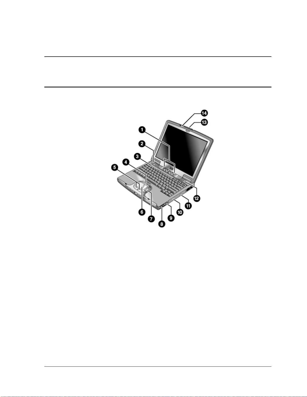
Figure 1. Front View
1. One-Touch buttons (programmable).
2. Power button.
3. Keyboard status lights: Caps Lock, Num Lock,
CD or DVD drive activity.
4. Touch pad/scroll pad on-off button (with on-off
indicators on either side).
5. Left and right click buttons .
6. Touch pad.
7. Scroll pad.
zt1000/xz300 and xt1500 Series Product Information 7
Troubleshooting and Self-Repair Guide
8. Volume controls (selected models).
9. Mute button and indicator light (selected models).
10. Removable DVD or DVD/CD-RW drive.
11. CD/DVD eject button.
12. Speaker (one on each side).
13. Latch.
14. Built-in microphone.
Page 8
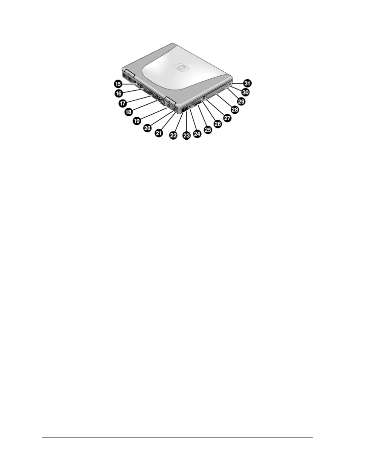
Figure 2. Back Vie w
15. AC adapter jack.
16. Parallel port (LPT1) (colored burgundy).
17. External monitor (VGA) port (colored blue).
18. Universal serial bus (USB) ports (2).
19. S-video (TV out) port (colored yellow) (selected
models).
20. Reset switch.
21. Kensington lock slot (security connector).
22. LAN port and indicators.
23. Modem.
24. IEEE 1394 connector (selected models).
25. SD-MMC Card slot.
26. PC Card slot (Type II).
27. PC Card eject button.
28. Hard disk drive.
29. Wireless on-off button and indicator light
(selected models).
30. Ex ternal microphone jack (colored pink).
31. Headphones jack (colored green).
8 Product Information zt1000/xz300 and xt1500 Series
Troubleshooting and Self-Repair Guide
Page 9
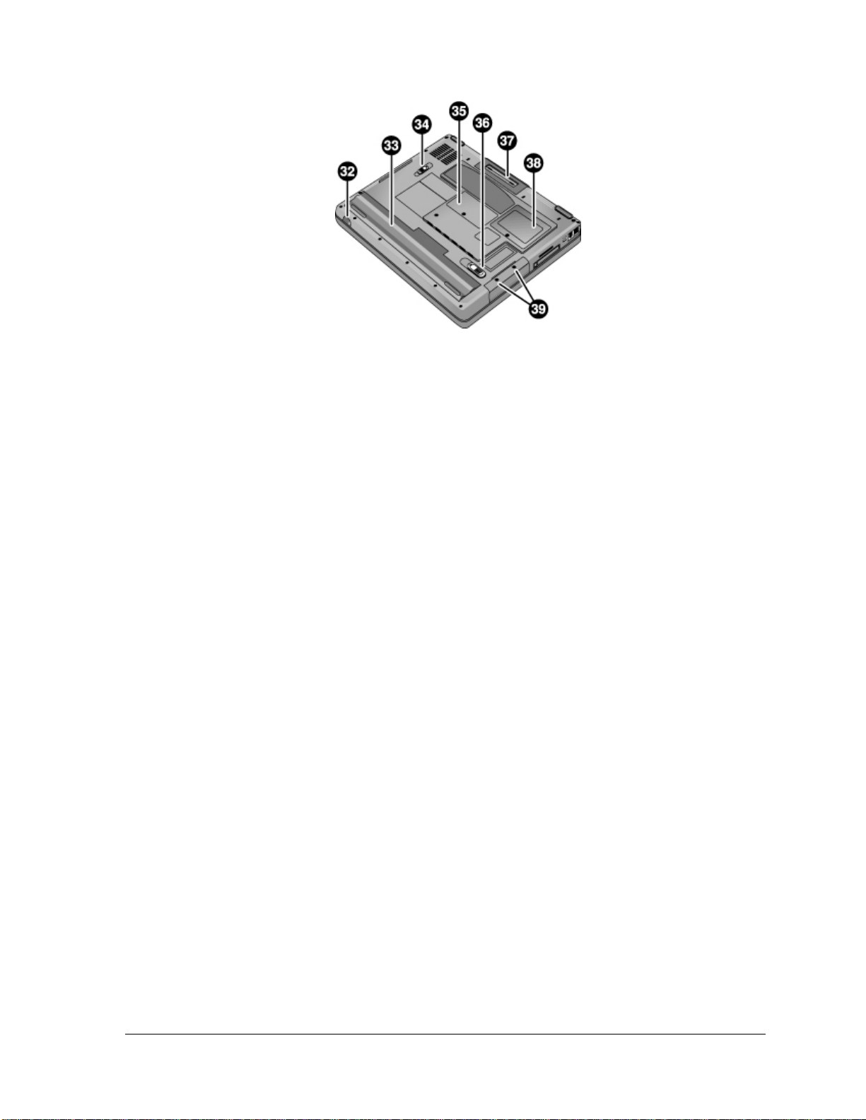
Figure 3. Bottom Vi ew
32. Infrared port (selected models).
33. Battery.
34. CD/DVD drive latch.
35. RAM cover.
36. Battery latch.
37. Docking port.
38. Mini-PCI cover (no userreplaceable parts inside).
39. Hard disk drive retaining screws.
zt1000/xz300 and xt1500 Series Product Information 9
Troubleshooting and Self-Repair Guide
Page 10
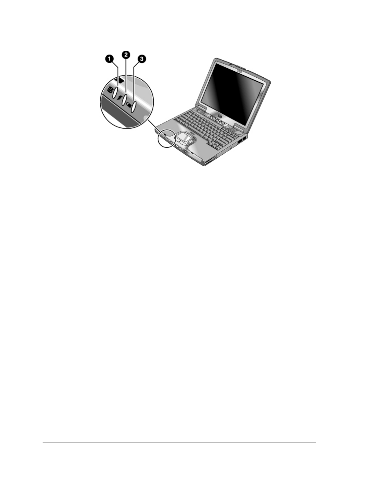
Figure 4. Main Stat us Lights
1. Hard disk drive activity.
• On: the notebook is accessing the hard disk drive.
2. Power mode.
• Green: the notebook is on (even if the display is off).
• Amber: the notebook is on standby.
• Off: the notebook is off or in hibernation.
3. Battery charge status.
• Green: the AC adapter is connected and the battery is fully charged.
• Amber: the AC adapter is connected and the battery is charging.
• Red: the AC adapter is connected and the battery has a fault.
• Off: the AC adapter is not connected or the battery is missing.
10 Product Information zt1000/xz300 and xt1500 Series
Troubleshooting and Self-Repair Guide
Page 11
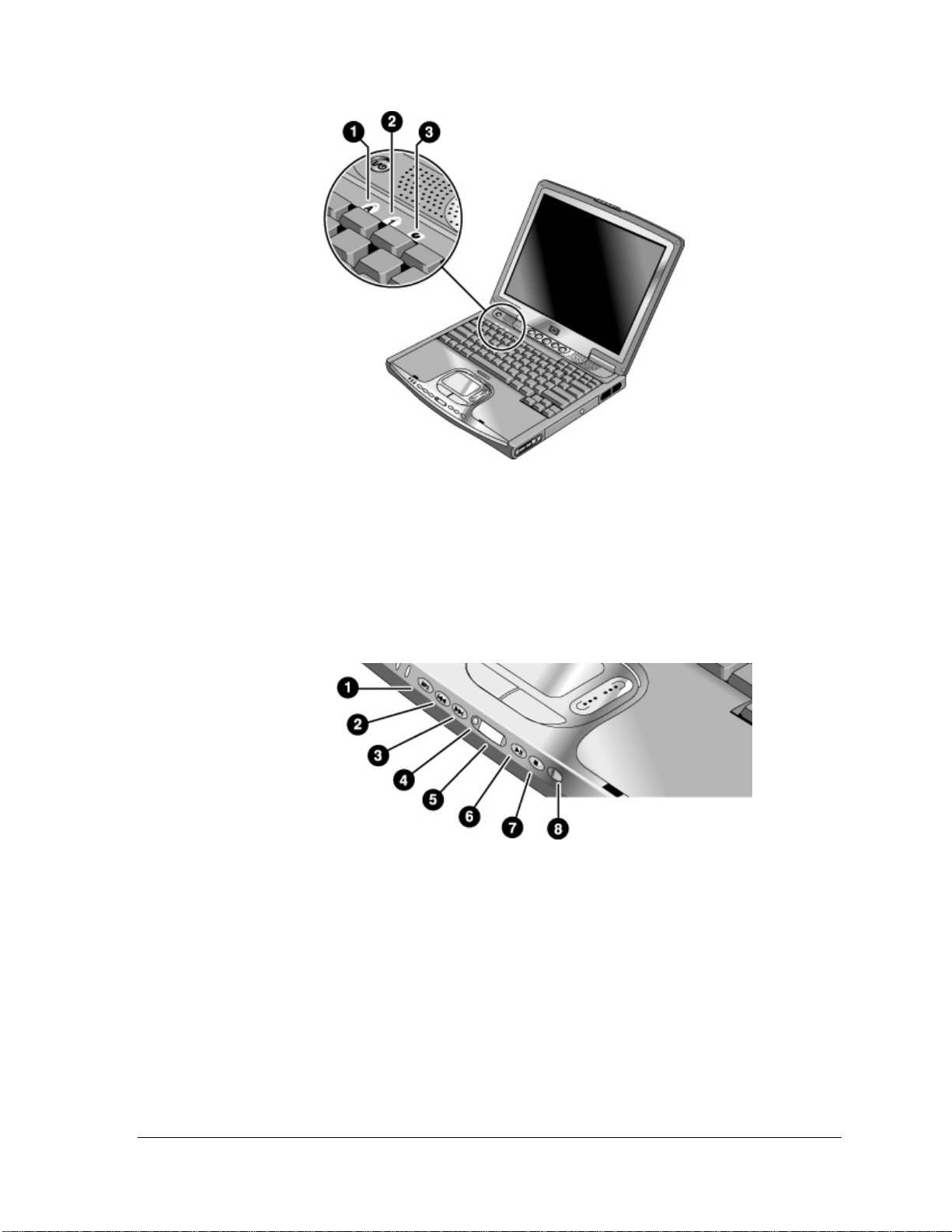
Figure 5. Keyboard Status Lights
1. Caps Lock. Caps Lock is active.
2. Num Lock. Num Lock is active. (The Keypad Lock must also be on to use the
embedded keypad.)
3. CD/DVD drive activity. The drive is active.
Figure 6. Multimedia Buttons and Status Panel (selected models)
1. MP3 player launch button.
2. Previous track button.
3. Next track button.
4. Status panel button.
5. Status panel.
6. Play/Pause button.
7. Stop button.
8. Multimedia power switch and
indicator light.
zt1000/xz300 and xt1500 Series Product Information 11
Troubleshooting and Self-Repair Guide
Page 12

Operating the Notebook
Note
This manual describes the notebook in its original factory configuration, with all settings at their
default values.
Turning the Notebook On and Off
Power mode To enter this mode To turn on again
On
Power mode status light is green.
Standby
Maintains current session in RAM.
Turns off the display and other components.
Saves significant power.
Restarts quickly.
Restores network connections.
Power mode status light is amber.
Hibernation
Saves current session to disk, then turns off.
Saves maximum power.
Restores network connections.
Power mode status light is off.
Turn off
Turns off without saving current session.
Saves maximum power.
At startup, resets everything, and starts a new
session.
Power mode status light is off.
Press the power button.
Click Start, Turn Off Computer,
Stand By.
–or–
Press the power button.
–or–
Allow timeout.
Click Start, Turn Off Computer,
then press and hold Shift and
click Hibernate.
–or–
Allow timeout.
Click Start, Turn Off Computer,
Turn Off.
–or–
Press and hold the power
button for four seconds (only
if the Start menu procedure
doesn’t work).
Press the power button to
quickly resume your
session.
Press the power button to
resume your session.
Press the power button to
start with a new session.
12 Product Information zt1000/xz300 and xt1500 Series
Troubleshooting and Self-Repair Guide
Page 13
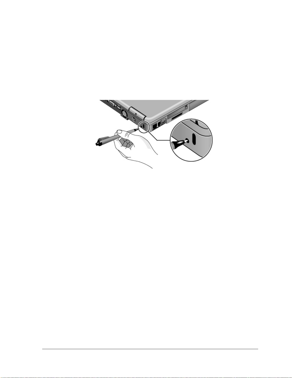
Resetting the Notebook
If Windows or the notebook stops responding and you cannot turn the notebook off, try the following
in the order listed. Press the power button to restart.
• Press Ctrl+Alt+Del, then click Shut Down, Turn Off.
• Press and hold the power button for about four seconds, until the display turns off.
• Use a pen or straightened paper clip to press the reset switch on the back of the notebook.
Figure 7. Pressing the Reset Switch
Changing the Boot Device
The notebook normally boots from its internal hard disk. You can also boot the notebook from an
external USB floppy disk drive (optional accessory), the CD/DVD drive, or a local area network
(LAN).
1. Restart the notebook: click Start, Turn Off Computer, Restart.
2. When the HP logo appears, press Esc to display the Boot menu.
3. Use the arrow keys to select the boot device, and press Enter.
If you want to boot from a specific device whenever it is present, change the boot order using the
BIOS configuration utility—see “Using the BIOS Configuration Utility” on page 32.
zt1000/xz300 and xt1500 Series Product Information 13
Troubleshooting and Self-Repair Guide
Page 14

Hardware Specifications
The specifications shown below are subject to change. For the latest specifications, see the HP
Notebook Web site (www.hp.com/notebooks).
Physical Attributes Dimensions:
14.1-in models: 330 × 278.3 mm (12.99 × 10.94 in).
15-in models: 330 × 278.3 mm (12.99 × 10.94 in).
Thickness varies across unit.
Weight varies with configuration, vendor components, and manufacturing options and
processes. Minimum weight (14.1-in model): 2.7 kg (5.9 lb).
Processor and
Bus Architecture
Graphics
Power
Mass Storage
CD/DVD drive
RAM
Audio System
Communications
Keyboard and
Pointing Devices
Intel Mobile Pentium 4 processor (1.7, 1.8, or higher MHz) with SpeedStep technology
(selected models).
Intel Pentium 4c processor (1.6 GHz) without SpeedStep technology (selected
models).
Intel Celeron processor (1.5GHz or higher) (on selected models).
14.1/15-in XGA (1024x768) or 15-in SXGA+ (1400x1050) TFT LCD display.
ATI Mobility Radeon graphics accelerator configurable for either 16- or 32-MB DDR
graphics memory, 4x AGP graphics capability.
Supports 16 million colors and OpenGL graphics.
Supports hardware acceleration for MPEG. Display driver supports MPEG2 overlay.
Supports LCD+CRT or LCD + TV operation (dual view).
Separate video memory.
Supports NTSC and PAL TV.
Dual display for LCD and external monitor or TV.
External color support: starting at 640 x 480, up to 1600 x 1200 x 32 bit display
resolution.
Rechargeable 8-cell Lilon battery: 14.8 V, 3900 mAH or 4200 mAH.
Battery life: up to 2.5 hours (varies with model and usage).
Battery recharge (100%): up to approx. 3 hours with system off (varies with model).
Low-battery warning.
Standby/hibernate and resume capability.
Universal AC adapter: 100–240 Vac (50/60 Hz) input, 19 Vdc output, 75 W, 3.95-amp,
387.5g, 127.3 mm x 51.5 mm x 29.3 mm.
20- to 60-GB removable IDE hard disk drive.
8X DVD or 24X8X8X8X DVD/CD-RW (or higher) removable drive.
Two slots for DDR SDRAM expansion (PC-2100) up to 2x512 MB.
266-MHz RAM bus for MP chipset and 512 MB (2*256 MB) for MZ chipset.
DirectSound.
MIDI (playback) support.
16-bit, full duplex stereo sound through two built-in speakers with integrated acoustic
chambers. 1.5 W per channel, 64 voices.
Built-in microphone.
Polk Audio certified on 15-in models (pavilion).
Dedicated mute and volume controls (selected models).
CD player (can play while notebook is on standby, in hibernation, or off).
3D-enhanced audio.
56 Kpbs Ambit modem.
10/100 LAN integrated.
87/88/91-key touch-type QWERTY keyboard with 101/102 key emulation.
Embedded numeric keypad.
12 function (Fn) keys.
5 user-programmable One-Touch buttons.
Touch pad with lock button and on-off indicator.
Left and right click buttons , vertical scroll pad.
14 Product Information zt1000/xz300 and xt1500 Series
Troubleshooting and Self-Repair Guide
Page 15

Wireless LAN
(selected models)
Input/Output
Expandability
Security Features
Environmental Limits
Major ICs
Radio: IEEE 802.11b, WECA Wi-Fi compliant, direct-sequence spread-spectrum.
Operating frequency: 2.5-GHz ISM band, exact frequencies and channels depend on
country.
Raw data rate: 1, 2, 5.5, or 11 Mbps.
Transmitter output: 15 dBm typical (approx. 30 mW), 16 dBm max (approx. 40 mW).
Receiver sensitivity: –84 dBm typical .
Range: up to 100 m (300 ft) or more, depending on environment and conditions.
On-off button and indicator.
Mini-PCI interface.
2 universal serial bus (USB) ports.
15-pin VGA video-out (blue) with DDC support. (Resolution up to 1600 × 1200 × 64K
or 16M colors. Refresh rate of 60 to 85 Hz, depending on resolution and color depth.)
RJ-11 jack for Mini-PCI type modem (selected models).
RJ-45 LAN jack.
25-pin bi-directional high-speed ECP/EPP parallel (burgundy).
S-video TV out (yellow) (selected models).
IEEE 1394 port (selected models).
4-Mbps IrDA-compliant infrared port (selected models).
One DC-in jack.
One microphone-in jack
One headphone-out jack.
One Type II 16-/32-bit PC Card slot (3.3- and 5-V support).
CardBus enabled.
One integrated Secure Digital Multi-Media Card slot.
Optional simple port replicator (selected models).
User and administrator passwords.
DMI-accessible electronic serial number.
Kensington MicroSaver lock slot.
Operating temperature: 0 to 40 °C (32 to 104 °F).
Operating humidity: 10 to 90 percent RH (0 to 40 °C).
Operating altitude: up to 10,000 ft (3000 m) at 25 °C (77 °F).
Storage (non-operating) temperature: –20 to 65 °C (–4 to 149 °F).
CPU: Intel Mobile Pentium 4 processor.
North Bridge: Intel 845MP or MZ.
South Bridge: Intel ICH3.
Display controller: ATI M7 with 32M DDR.
Audio controller: Intel ICH3/Realtek ALC202 AC97 Codec.
CD player controller: O2 OZ-163.
LAN: Realtek RTL8100L.
CardBus controller: ENE 1410
Keyboard/embedded controller: National NS87591.
Super I/O: SMSC LPC47N227.
SD/MMC controller: W83L518D
IEEE 1394 controller: VIA VT6306
zt1000/xz300 and xt1500 Series Product Information 15
Troubleshooting and Self-Repair Guide
Page 16

Troubleshooting and Diagnostics
This section contains solutions to several types of problems you may encounter when using the
notebook. Try the solutions one at a time, in the order in which they are presented.
You can also find technical tips and software updates for the notebook at the HP Business Support
Web site (www.hp.com/go/bizsupport).
Audio Problems
If no sound is audibl e
• Press Fn+Page Up several times.
• If available, press the rear volume control several times.
• Click the speaker icon in the taskbar, and make sure Mute is not checked and the Volume slider is
not set to the bottom.
• If available, press the mute button on the right side of the notebook once or twice until the
indicator light goes off.
If sound does not rec ord
• Check the software controls for recording sound: click Start, All Programs, Accessories,
Entertainment, Sound Recorder.
• In Volume Control, click Options, Properties, and make sure the microphone is enabled in the
recording controls.
• Test the audio with the e-DiagTools diagnostics— see “Using the e-DiagTools Diagnostic Tests”
on page 31.
If you hear a loud high-pitched whine (feedback) from the spea kers
• In Volume Control, try reducing the master volume.
• In Volume Control, click Options, Properties, and select the microphone option for the playback
settings. Then in Volume Control, make sure the microphone is muted.
• Avoid using the built-in microphone and built-in speakers at the same time.
16 Troubleshooting and Diagnostics zt1000/xz300 and xt1500 Series
Troubleshooting and Self-Repair Guide
Page 17

CD and DVD Problems
If you can’t boot fro m a C D i n t he D VD/CD-RW drive
• Make sure the CD is bootable, such as the Recovery CDs.
• Make sure the DVD/CD-RW drive is selected as the boot device—see “Changing the Boot
Device” on page 13.
• Restart the notebook.
• Test the DVD/CD-RW drive with the e-DiagTools diagnostics— see “Using the e-DiagTools
Diagnostic Tests” on page 31.
If a CD or DVD plays erratically
• Dirt or smudges can cause a disk to skip. Clean the disk with a soft cloth. If the disk is badly
scratched, it will probably have to be replaced.
• Some DVDs include software called “PC Friendly.” You generally should not install this
software, as it can cause errors or erratic play. If needed, uninstall it and restart your notebook.
If a DVD movie stops playing in the middle
• You may have accidentally paused the DVD movie. Press the Play button to continue.
• The DVD may be double-sided. Open the DVD tray and read the text near the center hole of the
disk. If it says Side A, flip the disk over, close the tray, and press the Play button to continue
playing the movie.
If you get a Region Code error when pl aying a DVD movie
• DVDs can have regional codes embedded in the disk data. These codes prevent DVD movies
from being played outside the region of the world in which they are sold. If you get a Region
Code error, you are trying to play a DVD intended for a different region.
Important: most DVD drives let you change the region code only a limited number of times
(usually no more than four). When you reach this limit, your last change to the region code will be
hard-coded on the DVD drive, and will be permanent. Your HP warranty does not cover the
expense of correcting this situation.
Refer to the help for your DVD player software for details about setting region codes.
If the notebook cannot read a C D or D V D
• For a single-sided CD or DVD, make sure the disk is placed in the drive with the label facing up.
• Clean the disk.
• Wait 5 to 10 seconds after closing the tray for the notebook to recognize the disk.
• Remove the disk from the drive, then restart the notebook.
• If you created the CD on a CD-RW drive module, try using a different media brand, such as the
recommended HP C4403A (CD-R) or C4404A (CD-RW) media. Read and write quality may vary
for other media.
zt1000/xz300 and xt1500 Series Troubleshooting and Diagnostics 17
Troubleshooting and Self-Repair Guide
Page 18

If a DVD movie doesn’t fill the screen
• Each side of a double-sided DVD has a different format (standard or widescreen). In widescreen
format, black bands appear at the top and bottom of the screen. To view the standard format, flip
the disk over and play the other side.
If a DVD doesn’t play with two displays
• If both displays are active, press Fn+F5 to switch to one display.
• If you’re using both displays, the DVD image will not appear on any display set up as
“secondary.” Click Start, Control Panel, Appearance and Themes, Display. Click Advanced on
the Settings tab, then click the Displays tab and change settings.
Display Problems
If the notebook does not recognize the display
When the notebook starts up, it automatically re-activates the display that was in use when Windows
was last shut down. If you dock to a simple port replicator or attach a monitor while the notebook is
off, the notebook may not properly recognize the monitor. If this happens, choose the display that you
want to use in either of these ways:
• Press Fn+F5. (Do this three times to return to the state you started from.)
• Click Start, Control Panel, Appearance and Themes, Display, Settings, and then click the
Advanced button. On the Displays tab, select the Display Device you want, and then click OK.
If the notebook is on, but the screen is blank
• Move the mouse or tap the touch pad or scroll pad. This will wake the display if it is off.
• Try pressing Fn+F2 to increase the display brightness.
• Press Fn+F5 in case the internal display was disabled. (Do this three times to return to the state
you started from.)
• If the notebook is cold, allow it to warm up.
If the screen is difficult to read
• Try setting the display resolution to its default of 1024×768: click Start, Control Panel,
Appearance and Themes, Display, Settings.
• Try adjusting the size of the desktop icons and labels.
If part of the Windows desktop is not vi sible and you have to scroll down to see the
taskbar, or if the desktop does not fill the entire display and has a black border
• Your display resolution may be set incorrectly. Adjust the resolution as needed.
If an external display does not work
• Check the connections.
• Press Fn+F5 in case the external monitor was disabled. (Do this three times to return to the state
you started from.)
• If you’re using a TV connected to the S-video port, you must activate the TV.
18 Troubleshooting and Diagnostics zt1000/xz300 and xt1500 Series
Troubleshooting and Self-Repair Guide
Page 19

• Test the display with the e-DiagTools diagnostics— see “Using the e-DiagTools Diagnostic
Tests” on page 31.
If one or more display pixels look bad
TFT display manufacturing is a highly precise but imperfect technology, and manufacturers cannot
produce displays that are cosmetically perfect. Most, if not all, TFT displays exhibit some level of
cosmetic imperfection. These cosmetic imperfections may be visible under varying display conditions,
and can appear as bright, dim, or dark spots. This issue is common across all vendors supplying TFT
displays in their products and is not specific to the HP notebook display.
HP notebook TFT displays meet or exceed all HP standards for cosmetic quality of TFT displays. HP
does not warrant that the displays will be free of cosmetic imperfections. TFT displays can have a
small number of cosmetic imperfections and still conform to HP’s cosmetic quality specifications,
including the following:
• No more than 6 pixels remain on (always one color, such as white, red, green, or blue dots).
• No more than 6 pixels remain off (always dark).
• No more than a total of 8 pixels stuck on or off.
• No other stuck pixel within 15 mm of a stuck pixel.
Contact HP Customer Care if you have a display quality problem and require a more comprehensive
explanation of HP display quality. We expect that over time the industry will continue to produce
displays with fewer inherent cosmetic imperfections, and we will adjust our HP guidelines as these
improvements are implemented.
Floppy Disk Drive Problems
If a floppy drive connected to the USB port doesn’t work
• Make sure the drive is securely connected to the notebook.
• Restart the notebook: click Start, Turn Off Computer, Restart.
Hard Disk Drive Problems
If the notebook’s hard drive doesn’t spin
• Make sure the notebook has power. If necessary, connect the AC adapter, and make sure it is fully
plugged into a power source and into the back of the notebook.
• Remove and reinsert the hard drive—see “Removing the Hard Disk Drive” on page 40.
If the hard disk makes a buzzing or whining noise
• Back up the drive immediately.
• See whether the noise is coming from elsewhere, such as the fan or a PC Card drive.
If files are corrupted
• Check the hard disk: open My Computer, select the disk you want to scan, click File, Properties,
and use the Tools tab.
• Run the Norton AntiVirus program.
zt1000/xz300 and xt1500 Series Troubleshooting and Diagnostics 19
Troubleshooting and Self-Repair Guide
Page 20

• Test the hard disk drive with the e-DiagTools diagnostics—see “Using the e-DiagTools
Diagnostic Tests” on page 31.
• If necessary, format the hard disk and reinstall the original factory software—see “Recovering the
Factory Software Installation” on page 35.
If the hard drive’s reported capacity is less than its actual size
• The hard disk drive is preconfigured to allocate some space to diagnostic software, which is used
for support and service of your notebook. This part of the hard drive is unavailable for other uses,
and so is not included in the capacity of the hard drive as reported by Windows (My Computer,
Properties).
Heat Problems
Keep in mind that your notebook normally gets warm during routine operation. Charging the battery
and running games and other programs that drive CPU usage toward 100% can further increase the
notebook’s temperature.
If the notebook gets war mer than usual
• Always set the notebook on a firm, flat surface, so that air can flow freely around and underneath
it.
• Make sure the air vents on the right side and back of the notebook are clear.
• Make sure the fan is working properly. If needed, test the fan’s operation—see “Using the e-
DiagTools Diagnostic Tests” on page 31.
Keyboard and Pointing Device Problems
If the pointer is difficult to control
• Adjust the pointer controls: click Start, Control Panel, Printers and Other Hardware, Mouse.
If the touch pad or scr oll pad doesn’t work
• Don’t use the touch pad or scroll pad while the notebook is starting up or resuming. If this
happens, try the following:
• Press any key on the keyboard.
• Put the notebook on standby, then resume operation.
• The touch pad and scroll pad are automatically disabled when the notebook is docked in a port
replicator that has a PS/2 mouse connected.
• Restart the notebook: click Start, Turn Off Computer, Restart.
• Check settings: click Start, Control Pad, Printers and Other Hardware, Mouse, Scrolling.
• Test the keyboard and pointing devices with the e-DiagTools diagnostics— see “Using the e-
DiagTools Diagnostic Tests” on page 31.
If the embedded numer ic keypad doesn’t work
• To type numbers, make sure Num Lock is on.
20 Troubleshooting and Diagnostics zt1000/xz300 and xt1500 Series
Troubleshooting and Self-Repair Guide
Page 21

• Make sure the embedded Keypad Lock (Fn+F8) is on—or that you press and hold the Fn key to
temporarily access the embedded keypad.
If you can’t type the euro symbol
• Hold Alt GR when you press the marked key.
• The euro symbol is not on the U.S. English keyboard. Make sure the embedded keypad is active
(Fn+F8) and Num Lock is on, then hold Alt while typing 0128 on the numeric keypad.
• Support for the euro symbol requires software available from Microsoft. This software is installed
in the factory software, but may not be included with retail Windows.
If a special feature on a USB mouse doesn’t work
• Make sure you installed any drivers included with the mouse.
• Restart the notebook, so that it will detect the mouse.
LAN Problems
If the built-in net work adapter doesn’t connect to the LAN
• Check all cables and connections. Try connecting at a different network station, if available.
• If the green light next to the LAN port does not light, the LAN cable may not be connected to the
network or the network may be down. Try connecting a different notebook to the cable.
• Click Start, Control Panel, Network and Internet Connections, Network Connections. Make sure
you have the correct clients and protocols installed.
• Make sure the LAN cable is Category 3, 4, or 5 for 10Base-T operation, or Category 5 for
100Base-TX operation. Maximum cable length is 100 meters (330 feet).
• Use the networking problems troubleshooter in Windows Help and Support.
• Click Start, Control Panel, Performance and Maintenance, System. On the Hardware tab, open the
Device Manager. If the network interface is disabled, try to enable it. If it has a conflict, try
disabling another device.
If you can’t bro wse My Network Places
• Click Start, Search to look for a computer.
If you can’t log i n to Netware servers
• If a Netware server is using IPX/SPX protocol, you may need to force your frame type to match
the server’s frame type. Check with your network administrator.
If the notebook stops responding after booting
• Check whether you have a TCP/IP network with no DHCP server. This can cause a long delay at
startup because DHCP is enabled. Contact your network administrator to determine the proper
TCP/IP configuration.
zt1000/xz300 and xt1500 Series Troubleshooting and Diagnostics 21
Troubleshooting and Self-Repair Guide
Page 22

Memory Problems
If a message says you are out of mem ory
• Make sure drive C is not running low on free space.
• Use the memory troubleshooter in Windows Help and Support.
• If you are having memory problems while running MS-DOS programs, use the application and
software problems troubleshooter in Windows Help and Support.
• Not all third-party memory cards have been tested for use with the notebook. Check the HP
Notebook Web site (www.hp.com/notebooks) for a list of approved and tested memory cards.
• Test your notebook’s memory with the e-DiagTools diagnostics— see “Using the e-DiagTools
Diagnostic Tests” on page 31.
If memory doesn’t increase after adding RAM
• Make sure your notebook is using only DDR 266 RAM modules.
Modem Problems
If the modem seems slow
• Check for excess static or noise on the line, which reduces the overall transmission speed. If
necessary, contact your telephone company about fixing this type of problem.
• If you’re dialing internationally, line noise is often difficult or impossible to eliminate.
• If you have call-waiting, disable it—your telephone company can provide instructions.
• Eliminate extra connections in the line. If possible, connect directly to the wall jack.
• Try another telephone line, preferably one normally used for a fax machine or modem.
If the modem doesn’t dial or no dial tone is detected
• Check all cables and connections.
• Connect a standard telephone to the phone line and make sure the line is working.
• Make sure someone else isn’t using the same phone line.
• Try another telephone line, preferably one normally used for a fax machine or modem.
• If you’re in a foreign country/region, the dial tone may not be recognized by the modem. Click
Start, Control Panel, Printers and Other Hardware, Phone and Modem Options. Select your
modem on the Modems tab, then click Properties, Modem, and disable the option that waits for a
dial tone.
• Many countries impose a blackout period after a modem repeatedly fails to connect to a service
provider. The number of failed attempts and the period you must wait before trying again differ
from country/region to country/region: check with your telephone company.
For example, if you are dialing from Italy and fail to connect to your server or cancel the
connection, you must wait one minute before dialing that number again. If you dial before then,
you will get an error message that says “delay.” After the fourth failed connection, you must wait
one hour before trying the number again. If you dial before the hour is up, you will get a message
that says “black list.”
22 Troubleshooting and Diagnostics zt1000/xz300 and xt1500 Series
Troubleshooting and Self-Repair Guide
Page 23

If the modem dials incorrectly
• Check the telephone number you entered, including any digits required for outside access or long
distance.
• In Control Panel, open Phone and Modem Options, and check the dialing options—look for
duplicate digits for outside access or long distance.
• Make sure the number you’re calling isn’t busy.
• If you’re in a foreign country/region, the dial tone may not be recognized by the modem. Click
Start, Control Panel, Printers and Other Hardware, Phone and Modem Options. Select your
modem on the Modems tab, then click Properties, Modem, and disable the option that waits for a
dial tone.
• If you have call-waiting, disable it—see Windows Help and Support, and contact your telephone
company for information.
If the modem dials but doesn’t connect
• Make sure you’re using an analog telephone line. You must not use a digital line. In a hotel, ask
for a data line.
• Try another telephone line, preferably one normally used for a fax machine or modem.
• The modem at the other end may have a problem. Try dialing to a different modem.
If the modem will not connect at 56K speed
• The host modem may not support a 56K (V.90) connection speed.
• Connection speed depends on several factors, such as the condition of the telephone line. Try
connecting another time.
If the modem will not connect at any speed
• Make sure you’re using an analog telephone line. You must not use a digital line. In a hotel, ask
for a data line.
• Make sure the telephone line goes directly from the notebook’s modem phone jack to the
telephone jack on the wall.
• If you have a single telephone line for voice and modem use, make sure no one else is using the
line and that the phone is not off the hook.
• Try another telephone line, preferably one normally used for a fax machine or modem.
• Contact your Internet Service Provider (ISP). It's possible that service may be unavailable
temporarily or that your settings are incorrect.
• Restart your notebook and attempt another connection.
• Download the latest modem driver from the technical support area of the HP notebook Web site
(www.hp.com/notebooks).
• Run the modem diagnostics:
1. Click Start, Control Panel, Printers and Other Hardware, Phone and Modem Options.
2. Click the Modems tab, and select the modem you want to test.
3. Click Properties, Diagnostics, Query Modem.
zt1000/xz300 and xt1500 Series Troubleshooting and Diagnostics 23
Troubleshooting and Self-Repair Guide
Page 24

If the modem isn’t detected
• Check the modem setup. In Control Panel, open Phone and Modem Options.
• Click Start, Control Panel, Performance and Maintenance, System. On the Hardware tab, open the
Device Manager. If the modem is disabled, try to enable it. If it has a conflict, try disabling
another device.
• If you’re running fax software using fax Class 2, try using Class 1.
If the modem dials but you can’t hear it
• If available, make sure the mute indicator is turned off. If it’s on, press the mute button.
• Check the speaker volume setting and mute setting.
• In Control Panel, open Phone and Modem Options. Select the modem and click Properties, then
check the volume setting on the Modem tab.
If the modem connect s, but t r ansferred data is bad
• In Control Panel, open Phone and Modem Options. Make sure the hardware settings match on the
sending and receiving modems.
If the modem causes an ERROR message
• A string of AT commands may contain an incorrect command. If you entered commands as extra
settings for the modem in Control Panel or in your communications software, check the
commands.
If the modem doesn’t fax
• If you’re using fax Class 2 in the fax software, try using Class 1.
• Close any other communications programs.
• If you’re faxing by printing from an application, make sure you’ve selected the fax printer.
• Try turning off power management features temporarily.
If the modem clicks repeatedly but doesn’t connect
• Make sure you’re using an analog telephone line. You must not use a digital line. In a hotel, ask
for a data line.
• Check all cables and connections.
One-Touch Button Problems
If One-Touch buttons are not working properly
• Make sure the items associated with the buttons are the ones you want.
If the onscreen display does not appear when pressi ng a One-Touch button
• Make sure the Onscreen Display is enabled.
24 Troubleshooting and Diagnostics zt1000/xz300 and xt1500 Series
Troubleshooting and Self-Repair Guide
Page 25

Parallel and USB Problems
If a USB mouse doesn’t work
• Make sure you followed the manufacturer’s installation instructions completely and have installed
the mouse properly. If not, repeat the procedure.
• Make sure the mouse is securely connected to the USB port.
• Put the notebook on standby, then resume.
• Restart the notebook.
• Check the mouse settings in Control Panel.
• Check the port settings in Control Panel: click Start, Control Panel, Performance and
Maintenance, System. On the Hardware tab, open the Device Manager, and double-click
Universal Serial Bus Controllers.
If a USB modem d oesn’t work properly
• See “Modem Problems” on page 22.
• Make sure the modem is securely connected to the USB port.
• Use the modem troubleshooter (under Networking problems) in Windows Help and Support.
• Check the modem settings in Control Panel.
• Disable the internal modem:
1. Click Start, Control Panel, Performance and Maintenance, System. On the Hardware tab,
open the Device Manager.
2. Double-click Modem to list the current modem devices.
3. Double-click the internal modem, then select the option to disable the modem.
• Check the port settings in Control Panel: click Start, Control Panel, Performance and
Maintenance, System. On the hardware tab, open the Device Manager, then double-click
Universal Serial Bus controllers.
If the parallel port is not working
• Make sure the port connection is secure.
• Check the port settings in Control Panel: click Start, Control Panel, Performance and
Maintenance, System. On the Hardware tab, open the Device Manager, and double-click Ports
(COM & LPT).
• Test the ports with the e-DiagTools diagnostics— see “Using the e-DiagTools Diagnostic Tests”
on page 31.
If the USB port is not working
• Contact the vendor of the peripheral device and check the HP Notebook Web site
(www.hp.com/notebooks) for the latest versions of the USB drivers and the driver for the device.
• Check the port settings in Control Panel: click Start, Control Panel, Performance and
Maintenance, System. On the Hardware tab, open the Device Manager, and double-click
Universal Serial Bus controllers.
• Test the USB port with the e-DiagTools diagnostics— see “Using the e-DiagTools Diagnostic
Tests” on page 31.
zt1000/xz300 and xt1500 Series Troubleshooting and Diagnostics 25
Troubleshooting and Self-Repair Guide
Page 26

PC Card (PCMCIA) Problems
If the notebook doesn’t recognize a PC Card
• Remove and reinsert the PC Card.
• Put the notebook on standby, then resume.
• Restart the notebook.
• If the card requires an IRQ, make sure one is available. If necessary, set the IRQ to an unused
value: click Start, Control Panel, Performance and Maintenance, System. On the Hardware tab,
open the Device Manager, then view resources by type.
• Check the HP Business Support Web site (www.hp.com/go/bizsupport) for information about
installing certain PC Cards.
• Make sure your notebook supports the problem PC Card: check the HP Notebook Web site
(www.hp.com/notebooks) for a list of approved and tested PC Cards.
• Try the card in another computer to see whether the card functions properly.
• Test the PC Card with the e-DiagTools diagnostics— see “Using the e-DiagTools Diagnostic
Tests” on page 31.
If an I/O card stops communicating properly
• The card may have been reset if your notebook went on standby or into hibernation, or turned off.
Exit any applications, then remove and reinsert the card.
If a PC Card modem is not working
• Disable the internal modem:
1. Click Start, Control Panel, Performance and Maintenance, System. On the Hardware tab,
open the Device Manager.
2. Double-click Modem to list the current modem devices.
3. Double-click the internal modem, then select the option to disable the modem.
Performance Problems
For best performance with Windows XP, your notebook should have at least 128 MB of memory
(RAM).
If the notebook paus es or runs sluggishly
• This may be normal Windows behavior. Background processing can affect response time.
• Certain background operations (such as a virus-scanning program) can affect performance.
• Certain demanding graphic games can affect performance.
• Press Ctrl+Alt+Del to see if an application is not responding.
• Restart the notebook.
• Some file browsers respond slowly while processing graphics or waiting for broken network
connections to time out.
26 Troubleshooting and Diagnostics zt1000/xz300 and xt1500 Series
Troubleshooting and Self-Repair Guide
Page 27

• If the notebook’s hard disk drive runs frequently (as indicated by the hard drive light on the front
of the notebook) while the notebook appears to be paused or running slowly, Windows is likely
spending excess time writing to its swap file on the notebook’s hard disk. If this occurs
frequently, consider installing additional memory.
• Check the amount of available free disk space. Delete temporary and unneeded files.
If the notebook stops respondi ng
• Press Ctrl+Alt+Del to end the application that is not responding.
• Press and hold the power button for at least four seconds to turn off and reset the notebook. Then
press the power button again to turn the notebook back on.
• If nothing happens, use a pen or straightened paper clip to press the reset switch on the back of the
notebook. Then press the power button to turn the notebook on.
Power and Battery Problems
If the notebook turns off immediatel y after it turns on
• Battery power is probably extremely low. Plug in the AC adapter or insert a charged battery.
If the notebook keeps beepi ng
• The notebook beeps repeatedly when battery power is low (you can set this option in Power
Options in Control Panel). Save your work, turn off the notebook immediately, and insert a
charged battery or plug in the AC adapter.
If the battery doesn’t charge
• Make sure the AC adapter is fully plugged into the power source and the notebook, and that the
light on the adapter is on.
• If you’re using a power strip, remove the AC adapter from the power strip and plug it directly into
a wall outlet.
• Make sure the battery is fully installed and locked in place.
• Move the notebook away from any nearby heat source. Unplug the AC adapter and allow the
battery to cool down. If the battery gets too hot, it will not charge properly.
• If available, try another battery and AC adapter.
If the notebook has a sh or t operating time
• Try conserving power using any of the suggestions listed in the online Reference Guide.
• If you are running an application that has an automatic save feature (such as MS Word), disable
this feature or increase the specified save time to reduce hard disk access.
• If the operating time has gradually become shorter and the battery is more than a year or two old,
you may need to replace the battery.
• Heavy modem use can affect battery operating time.
zt1000/xz300 and xt1500 Series Troubleshooting and Diagnostics 27
Troubleshooting and Self-Repair Guide
Page 28

• PC Card use can affect battery operating time.
If the Time Remaining for the battery seems incorrect
• The Time Remaining is an estimate based on the rate at which the notebook is using power at that
instant. So, if you check the Time Remaining while the notebook is using a good deal of power
(such as when reading from a CD or DVD), the value will likely show less time remaining than
you really have, since you will probably later switch to tasks that require less power.
If the notebook doesn’t go on sta nd by as expected
• If you have a connection to another computer, the notebook won’t go on standby if the connection
is active.
• If the notebook is performing an operation, it normally waits for the operation to finish before
going on standby.
If the notebook doesn’t automati cal l y hibernate as expected
• Make sure hibernate support is enabled: click Start, Control Panel, Performance and Maintenance,
Power Options, then click the Hibernate tab.
Also, check the Power Schemes tab. Make sure the hibernation timeouts for AC power and
battery power are not set to Never.
Printing Problems
Hint
You can solve most printing problems by using the printing troubleshooter in Windows Help and
Support.
If a printer doesn’t print
• Make sure the printer is on and has paper in it.
• Make sure you are using the correct printer cable or cable adapter, and that the cable is secure at
both ends.
• Check for printer errors.
If the left edge of the pri nt ed output is missing
• Certain applications may not work properly with 600-dpi printers. If you’re using such a printer,
try selecting a compatible printer driver for a 300-dpi printer. For example, if you were using a
600-dpi HP LaserJet printer, you might try using the HP LaserJet IIIsi driver (300 dpi).
Startup Problems
If the notebook doesn’t respond when you turn it on
• Connect the AC adapter.
• Reset the notebook by using a pen or straightened paper clip to press the reset switch on the back
of the notebook. Then press the power button to turn the notebook on.
28 Troubleshooting and Diagnostics zt1000/xz300 and xt1500 Series
Troubleshooting and Self-Repair Guide
Page 29

• Don’t use the touch pad while the notebook is starting up or resuming from standby or
hibernation.
• If the notebook still doesn’t respond, remove the battery and AC adapter, and remove any PC
Card. Then reset the notebook using the reset switch on the back of the notebook, replace the
battery and plug in the AC adapter, and turn on the notebook by pressing the power button.
• If the notebook still doesn’t respond, call HP for assistance.
If the notebook won’t boot from battery power
• Make sure the battery is properly inserted and fully charged. Check the battery’s charge by
clicking the power icon in the taskbar, or using Power Options in Control Panel.
• If available, try another battery.
If the notebook won’t boot f r om t he f l oppy disk drive
• Make sure the drive is connected correctly.
• Make sure the floppy disk drive is selected as the boot device—see “Changing the Boot Device”
on page 13.
Standby and Resume Problems
If the notebook takes a long time to resume after being on standby
• The notebook can take a minute or longer to resume if a network card is installed. A blinking
cursor appears on the display while the system is loading and checking hardware and network
connections. As soon as the hardware is reinitialized, the Windows desktop appears.
If you have general pr oblems resuming from standby or hi ber nat i on
• Close all applications before going on standby or into hibernation.
• If the problems appeared after you installed new software (including drivers, such as printer
drivers), uninstall the software. Contact the software application or device vendor for additional
support.
Wireless Problems
If you have problem s with wireless com m unication
• Make sure the wireless indicator light is on.
• See “LAN Problems” on page 21.
If you have trouble connecting to another computer in My Network Places
• Wait a few minutes, then press F5 to refresh the list of computers on the network.
• Click Start, Search to locate the computer.
zt1000/xz300 and xt1500 Series Troubleshooting and Diagnostics 29
Troubleshooting and Self-Repair Guide
Page 30

If you cannot connect to a particular computer on the network
• Make sure the computer is properly connected to the network.
• Make sure your TCP/IP setup is correct for your network: click Start, Control Panel, Network and
Internet Connections, Network Connections. Contact your system administrator for the correct
settings.
If your 802.11b wireless connection is dropped
• Press the blue LED button on the left side of your notebook, wait 5 seconds, and then press the
button again to reconnect.
• Move closer to the access point (for an infrastructure connection) or other wireless computer (for
an ad hoc connection).
If the wireless link icon in the taskbar is red
• Make sure you are using the correct SSID and channel settings: click the wireless link icon in the
taskbar and select Advanced Configuration. Contact your system administrator for the correct
settings.
• Make sure you are in range of an access point (for an infrastructure connection) or other wireless
computer (for an ad hoc connection).
If you can connect, but t he network is slow
• Check whether you might be in an area served by more than one wireless LAN. If so, the LANs
could be interfering with each other.
• Move closer to the access point (for an infrastructure connection) or other wireless computer (for
an ad hoc connection). You could be too far away for high-speed communication.
• Stop using any USB device that may be transferring large amounts of data, or adjust application
settings to reduce the transfer rate.
30 Troubleshooting and Diagnostics zt1000/xz300 and xt1500 Series
Troubleshooting and Self-Repair Guide
Page 31

Using the e-DiagTools Diagnostic Tests
The e-DiagTools hardware diagnostic program included with your notebook provides two levels of
testing: automated testing using its basic hardware test, and advanced testing using individual
hardware tests.
The tests are designed to run after the system reboots. This ensures that the notebook will be in a
predictable state, so the diagnostic program can properly test the hardware components. The tests are
non-destructive and are intended to preserve the state of the notebook. The notebook reboots when
you exit the program so drivers can be loaded.
Running basic tests and d ocumenting the results
1. In Windows, click Start, All Programs, Hewlett-Packard, Notebook, HP e–DiagTo ols, e –
DiagTools for Windows.
2. Click Support Ticket, and then click Update. e–DiagTools creates a new support ticket.
3. When e–DiagTools displays a dialog box about restarting the notebook, close all files and
applications before clicking Yes.
Viewing the support tic ket
1. In Windows, click Start, All Programs, Hewlett-Packard, Notebook, HP e–DiagTo ols, e –
DiagTools for Windows.
2. Click View to display the Support Ticket.
3. To add information about your problem, click Comments and type the information, then click OK.
To save or print the Support Ticket, click Save As or Print.
To e-mail the Support Ticket to your support agent, click e-Mail. The first time you make an e-
mail connection from this program, click Change Settings in the Connect window and enter the
settings recommended by your support agent.
Running advanced tests o n specific hardware
1. Restart the notebook: click Start, Turn Off Computer, Restart.
2. When the HP logo appears, press F10 to start the diagnostic test.
3. When the menu appears, press F2 to run e–DiagTools.
The first time you run the program, you are prompted to select the language for the program.
4. When the Configuration Description appears, verify the list of detected hardware.
5. Run the basic test. Press F2 to start the basic hardware test. The results appear when the test is
complete.
6. Press F2 to open the advanced test screen.
7. Use the arrow keys and ENTER to select the tests that you want to run. Tests are listed only for
detected hardware.
8. Press F2 to run the selected tests and add the results to the Support Ticket.
9. Press F12 to run the selected tests in a loop until you press ESC. When running advanced tests in
a loop, ESC does not stop all tests immediately.
zt1000/xz300 and xt1500 Series Troubleshooting and Diagnostics 31
Troubleshooting and Self-Repair Guide
Page 32

10. After each run, press F2 to go back to the advanced tests screen, press F4 to view the support
ticket, or press F3 to exit.
e-DiagTools for Windows can also update the version of e-DiagTools on your notebook’s hard disk.
In e-DiagTools for Windows, use the e-DiagTools menu.
If you have trouble running e-DiagTools from the hard disk, you can also run it from the Recovery
CDs. Boot from disk 1 and select the diagnostics option.
Using the BIOS Configuration Utility
The BIOS (Basic Input and Output System) configuration utility enables you to change the notebook’s
system configuration, and to tailor the operation of your notebook to your individual work needs.
1. Restart the notebook: click Start, Turn Off Computer, Restart.
2. When the HP logo appears, press F2 to enter the BIOS configuration utility.
3. The pointing devices are not active in the BIOS configuration utility, so you will need to use the
keyboard to navigate:
• Press the left and right arrow keys to move among menus.
• Press the up and down arrow keys to move among parameters in a menu.
• Press Enter to open the dialog for the current parameter, or to select the parameter.
• Press Tab or the left and right arrow keys to move among selections in a dialog.
• Press the up and down arrow keys to move through values for the setting.
• Press Enter to close the dialog and accept the settings.
4. After you select the options you want, use the Exit menu to exit the BIOS configuration utility.
The following tables describe the settings for the notebook’s initial BIOS release. If your notebook’s
BIOS version is different, some settings may differ from those shown, or may be absent.
Main Menu
Setting Description Default
BIOS Revision Shows the current BIOS version. Detected
automatically.
Service ID (Born On Date) Displays an identifier used for repair service. Detected
automatically.
Serial Number Displays the serial number as shown on the back of the unit. Detected
automatically.
UUID Number Displays the value of the 16-byte UUID (Universally Unique ID)
as 32 hex characters.
Platform Branding ID Displays the product family. Detected
System Time Sets the time using 24-hour format. Values set take effect
immediately.
System Date Sets the date using dd/mm/yy format (except English, which
uses mm/dd/yy format).
Internal Hard Disk Sets the hard disk drive type and various parameters. Detected
Detected
automatically.
automatically.
automatically.
32 Troubleshooting and Diagnostics zt1000/xz300 and xt1500 Series
Troubleshooting and Self-Repair Guide
Page 33

Extended Memory Shows the extended memory size. Detected
automatically.
LCD Status Panel Display Sets whether the status panel on the front of the notebook is
enabled.
LCD Status Panel Date
Format
LCD Status Panel Time
Format
Language Sets the language for the BIOS menus. English (US)
Security Menu
Setting Description Default
User Password is Shows if a user password is set. Clear
Administrator Password is Shows if an administrator password is set. Clear
Set User Password Press ENTER to set, change, or clear the user passwo rd. The
Set Administrator
Password
Password Required to
Boot
Boot Menu
Sets the date format for the status panel. mm/dd/yy
Sets the time format for the status panel. hh:mm AM/PM
password can have no more than 8 characters (0-9, A-Z), and
cannot include special or accented characters.
Press ENTER to set, change, or clear the administrator
password, which protects BIOS Setup settings. The password
can have no more than 8 characters (0-9, A-Z), and cannot
include special or accented characters.
Sets whether a user password is required when the computer
boots. Requires the administrator password for changes.
Enabled
Enter
Enter
Disabled
Setting Description
Hard Drive
CD-ROM/DVD
USB Floppy
Network Boot
Exit Menu
Setting Description
Save Changes and Exit Saves Setup changes, and then exits and reboots.
Discarding Changes Discards any Setup changes made since last save, and then
Get Default Values Restores default settings, and remain s in Setup. Does not
Shows the order of boot devices. Move the entries to change
the order. Network Boot provides diskless boot from a
network server.
exits and reboots. Does not affect password, date, or time
changes.
affect password, date, or time changes.
1. Hard Drive
2. CD-ROM/DVD
3. USB Floppy
4. Built-in LAN
zt1000/xz300 and xt1500 Series Troubleshooting and Diagnostics 33
Troubleshooting and Self-Repair Guide
Page 34

Page 35

Reinstalling and Updating Software
You can use the Recovery CDs or DVDs to recover the original factory software for your notebook.
The Recovery CDs or DVDs also provide Windows drivers specific to your notebook to configure a
custom system. You can find drivers in these locations:
• On your notebook’s hard drive under C:\hp\Drivers.
• On the Recovery CD or DVD under \hp\Drivers.
• On the HP Business Support Web site (www.hp.com/go/bizsupport). This Web site contains the
latest updates of software drivers for different operating systems.
Recovering the Factory Software Installation
You can use the Recovery CDs or DVDs to reinstall the original factory software on your notebook’s
hard disk. You can also use the same process to create a larger Utility partition on your hard disk, or to
create a Utility partition on a new hard disk. The hidden Utility partition contains the e-DiagTools
diagnostic tests and stores hibernation data for operating systems that don’t provide hibernation.
CAUTION
This procedure formats the notebook’s hard disk drive and erases all data on the disk. After the
hard disk is formatted, you’ll need to reinstall your applications.
Do not interrupt the following process or unplug the AC adapter until the process is complete.
1. Important: back up all data from your hard disk. The following steps delete all data from the
disk.
2. Connect the AC adapter to the notebook.
3. Insert the Recovery CD (disk 1) or DVD into the notebook’s DVD/CD-RW drive. If the notebook
is turned off, use a pin or straightened paper clip to press the release switch on the drive door to
open it.
4. Turn on or restart the notebook. If the notebook is running, click Start, Turn Off Computer,
Restart.
5. When the HP logo appears, press Esc to display the Boot menu.
6. Use the arrow keys to select the DVD/CD-RW drive as the boot device, and press Enter.
7. When the Rec overy C D or DVD dialog box appears, follow the displayed instructions. If
prompted, accept the recommended partition size. If you install the factory software, the recovery
process can take up to 15 minutes.
If you want to create the Utility partition without installing the factory software, click Advanced
and select not to install the operating system.
If your hard disk is partitioned into several drives, you can install the factory software on drive C
without affecting other drives. Click Advanced and select to restore only the C partition.
8. Important: when prompted to reboot the notebook, press Ctrl+Alt+Del and follow any
instructions that appear.
zt1000/xz300 and xt1500 Series Reinstalling and Updating Software 35
Troubleshooting and Self-Repair Guide
Page 36

Updating the Notebook BIOS
Hewlett-Packard may provide updates to the notebook’s BIOS to enhance the capabilities of your
system. Check the HP Business Support Web site (www.hp.com/go/bizsupport). Installation utilities
and instructions will be provided with the updates.
Updating the Windows Drivers
From time to time, HP releases updated versions of the drivers for your notebook. These updates are
intended to fix any problems that could be encountered in the drivers, and to keep your notebook
running smoothly. In addition, HP normally provides drivers for other versions of Microsoft
Windows, in case you decide to install a different version of Windows.
• Download the latest drivers for your notebook from the HP Business Support Web site
(www.hp.com/go/bizsupport). Follow the instructions included with the drivers.
36 Reinstalling and Updating Software zt1000/xz300 and xt1500 Series
Troubleshooting and Self-Repair Guide
Page 37

Removing and Replacing Parts
This chapter shows how to remove and replace the notebook’s user-replaceable components.
Caution
Always provide proper grounding when performing repairs. Without proper
grounding, an electrostatic discharge can damage the notebook and its
components.
Notes
To reassemble a component, perform the removal procedure in reverse order. Any special notes
required for reassembly are included at the end of each section.
Symbols like this are used throughout this chapter to show approximate full-size screw
outlines. Use these to verify the sizes of screws before you install them. Installing a wrong-size
screw can damage the notebook. (The symbol shown represents an M2.5×5mm T-head screw.)
Notes
Please refer to the “hp parts home” on the Web for the latest part numbers.
www.hp.com/hps/parts
zt1000/xz300 and xt1500 Series Removing and Replacing Parts 37
Troubleshooting and Self-Repair Guide
Page 38

Removing the Battery
Table 1. Battery Replacement Part Numbers
Description Part Number Exchange Part Number
Battery, LiIon 8-cell F3172-60901
Required Equipment
• None.
Removal Proced ur e
• Slide the battery’s release latch in the direction of the arrow on the latch, then lift the battery out
of its compartment.
Figure 8. Removi ng t he Battery
Reassembly Notes
• Insert the front end of the battery into the battery compartment, then press the back end in until
the battery clicks into place.
38 Removing and Replacing Parts zt1000/xz300 and xt1500 Series
Troubleshooting and Self-Repair Guide
Page 39

Removing the Optical Drive Module
Table 2. Optical Drive Module Replacement Part Nu mbers
Description Part Number Exchange Part Number
Drive, DVD module F5535-60911
Drive, DVD/CD-RW Combo module F5535-60912
Required Equipment
• None.
Removal Proced ur e
• Slide the module release latch in the direction shown by the arrow on the latch, and remove the
module.
Figure 9. Releasing the Plug-in Module
zt1000/xz300 and xt1500 Series Removing and Replacing Parts 39
Troubleshooting and Self-Repair Guide
Page 40

Removing the Hard Disk Drive
Table 3. Hard Disk Drive Replacement Part Numbers
Description
HDD-20GB 9.5mm IBM ATA100 FDB 0950-4318 F3257-69501
HDD-20GB 9.5mm, TOSH ATA100 FDB 0950-4287 F3476-69002
HDD-30.0GB 9.5mm, IBM ATA100 FDB (Cascade) 0950-4319 F3414-69500
HDD-40GB 9.5mm, IBM ATA100 FDB 0950-4320 F3428-69500
HDD-40GB 9.5mm,Toshiba ATA100 0950-4288 F3378-69102
Tray, HDD F3398-60914
Part Number
Exchange Part
Number
Required Equipment
• #0 Phillips screwdriver.
Removal Proced ur e
1. Unplug the AC adapter, if present, and remove the battery.
2. On the bottom of the unit, remove both hard drive retaining screws.
Screws,
M2.5×4mm
Figure 10. Removing the Hard Disk Drive
3. Carefully pull the hard drive out of the notebook.
4. Remove all four screws from the hard drive tray and drive case, then lift the drive out of the tray.
40 Removing and Replacing Parts zt1000/xz300 and xt1500 Series
Troubleshooting and Self-Repair Guide
Page 41

Screws,
M2.5x4mm (2)
Screws,
M2.5x4mm (2)
Figure 11. Removing the Hard Disk Tray
Reassembly Notes
• Insert the connector end of the drive through the opening in the tray, then lower the drive into
place.
• Carefully slide the hard drive assembly into its compartment. Press firmly to make sure the
connector seats properly.
Important
If you are installing a new hard disk drive, install the factory software and operating system on the
drive before loading any additional software—see “Recover ing the Fact or y Soft war e Insta llati on”
on page 35.
zt1000/xz300 and xt1500 Series Removing and Replacing Parts 41
Troubleshooting and Self-Repair Guide
Page 42

Removing the Mini-PCI Card
Certain notebook models include a mini-PCI card that contains either a modem or combined modem
and 802.11 wireless.
Table 4. Mini-PCI Card R epl acement Part Numbers
Description Part Number Exchange Part Number
PCA, mini-PCI (modem) F3377-60950
PCA, mini-PCI (modem/802.11) F3377-60951
Caution
Provide proper grounding and handle the card only by its edges, or you could damage it through
electrostatic discharge.
Required Equipment
• #0 Phillips screwdriver.
Removal Proced ur e
1. Unplug the AC adapter, if present, and remove the battery.
2. On the bottom of the notebook, loosen the screw holding the mini-PCI cover (the cover retains the
screw), and remove the cover.
3. Press outward to release the latches at the sides of the card, and carefully lift its free edge up.
4. Disconnect the cable(s) from the card.
5. Gently pull the card out of its connector.
42 Removing and Replacing Parts zt1000/xz300 and xt1500 Series
Troubleshooting and Self-Repair Guide
Page 43

Figure 12. Remov i ng t he Mini-PCI Card
Reassembly Notes
• Reattach the cable(s) to the card, and tuck them into the compartment.
• Gently press the card into the connector at an angle of about 30°, until it is fully inserted. Then
press down on both sides of the card until the latches snap closed.
zt1000/xz300 and xt1500 Series Removing and Replacing Parts 43
Troubleshooting and Self-Repair Guide
Page 44

Removing the Keyboard Cover
Table 5. Keyboard Cover Replacement Part Numbers
Description Part Number Exchange Part Number
Cover, keyboard (with LED lens) F3398-60917
Required Equipment
• #0 Phillips screwdriver.
• Small flat-blade screwdriver.
Removal Proced ur e
1. Unplug the AC adapter, if present, and remove the battery.
2. Close the notebook’s display, and remove both screws from the backs of the hinge covers.
Screws,
M2.5x4mm (2)
Figure 13. Remov i ng t he Keyboard Cover Retaining Screws
3. Open the display so that it lays flat.
4. Use the flat-blade screwdriver to carefully pry up the right end of the keyboard cover just above
the Page Up key, then lift the end until the cover unsnaps.
Caution
When removing the keyboard cover, be careful not to pull on the cable that connects the
keyboard cover to the notebook.
5. Carefully lift the cover to unsnap the latches above the center One-Touch button and the F1 key,
then lift the cover about an inch off of the notebook.
6. Disconnect the keyboard cover switch cable from the motherboard, and remove the cover from
the notebook.
44 Removing and Replacing Parts zt1000/xz300 and xt1500 Series
Troubleshooting and Self-Repair Guide
Page 45

Figure 14. Removing the Keyboard Cover
Reassembly Notes
• Make sure the keyboard cover switch cable is securely connected to the motherboard.
• Bend the center of the keyboard cover upward slightly, and insert the tabs on the ends of the cover
into the slots in the notebook’s case. Fit the hinge covers over the hinges, and gently press the
cover into place.
zt1000/xz300 and xt1500 Series Removing and Replacing Parts 45
Troubleshooting and Self-Repair Guide
Page 46

Removing the Keyboard
Table 6. Keyboard Replacement Part Numbers
Description Part Number Exchange Part
Number
Keyboard, French (zt1100/xz2 00 series only) F3428-60903
Keyboard, French Canadian (zt1100/xz200 series only) F3428-60909
Keyboard, German (xt1500 series only) (Europe only) F3428-60911
Keyboard, International English (xt1500 series only) (Europe only) F3428-60912
Keyboard, Italian (xt1500 series only) (Europe only) F3428-60904
Keyboard, Spanish F3428-60905
Keyboard, Swiss (xt1500 series only) (Europe only) F3428-60908
Keyboard, UK English (zt1100/xz200 series only) F3428-60902
Keyboard, US English (zt1100/xz200 series only) F3428-60901
Required Equipment
• #0 Phillips screwdriver.
• Small flat-head screwdriver.
Removal Proced ur e
1. Unplug the AC adapter, if present, and remove the battery.
2. Remove the keyboard cover (page 42).
3. Loosen the three retaining screws along the top of the keyboard (the keyboard retains the screws).
Figure 15. Looseni ng the Keyboard Ret a ining Screws
Caution
When opening the keyboard, be careful not to pull on the ribbon cable that connects the keyboard
to the notebook.
46 Removing and Replacing Parts zt1000/xz300 and xt1500 Series
Troubleshooting and Self-Repair Guide
Page 47

4. Raise the top of the keyboard, then lift the keyboard up and out of the notebook.
5. Lay the keyboard face down on the top case, forward of its normal position, and disconnect the
ribbon cable from the motherboard.
Warning
Do not touch the metal surfaces inside the notebook until they have cooled off. They could
be very hot if the notebook was running recently.
Figure 16. Disconnecting the Keyboard
Reassembly Notes
• Lay the keyboard face down on the top case, forward of its normal position, and reconnect the
ribbon cable.
• Slip the metal tabs on the bottom of the keyboard into their slots in the top case, then lower the
keyboard into place.
zt1000/xz300 and xt1500 Series Removing and Replacing Parts 47
Troubleshooting and Self-Repair Guide
Page 48

Removing an SDRAM Module
The notebook has no SDRAM built into its motherboard, but has two slots for PC133 SDRAM
modules: a system SDRAM slot beneath the keyboard (containing an SDRAM module installed at the
factory), and an expansion slot on the bottom of the unit.
Table 7. SDRAM Modul e Replacement Part Numbers
Description Part Number Exchange Part Number
Module, SDRAM, 128 MB DDR, PC266 SODIMM F4694-60901
Module, SDRAM, 256 MB DDR, PC266 SODIMM F4695-60901
Module, SDRAM, 512 MB DDR, PC266 SODIMM F4696-60901
Caution
Provide proper grounding and handle the SDRAM module only by its edges, or you could
damage the module through electrostatic discharge.
Required Equipment
• #0 Phillips screwdriver.
Removing an Expansion SDRAM Module
Removal Proced ur e
1. Unplug the AC adapter, if present, and remove the battery.
2. On the bottom of the notebook, loosen the screw holding the SDRAM cover (the cover retains the
screws), and remove the cover.
3. Press outward to release the latches at the sides of the SDRAM module (so that the free edge of
the module pops up), then pull the module out of the connector.
Figure 17. Remov i ng an Expansion SDRAM Modul e
48 Removing and Replacing Parts zt1000/xz300 and xt1500 Series
Troubleshooting and Self-Repair Guide
Page 49

Reassembly Notes
• Carefully press the SDRAM module into the connector at an angle of about 30°, until it is fully
inserted. Then press down on both sides of the module until the latches snap closed.
Figure 18. Installi ng an Expansion SDRAM Module
Removing the System SDRAM Module
Removal Proced ur e
1. Unplug the AC adapter, if present, and remove the battery.
2. Remove the keyboard cover (page 42).
3. Open the keyboard (page 46, steps 1 though 5). You don’t need to disconnect the keyboard cable.
4. Press outward to release the latches at the sides of the SDRAM module (so that the free edge of
the module pops up), then pull the module out of the connector.
Figure 19. Removing the System SDRAM Module
Reassembly Notes
• Carefully press the SDRAM module into the connector at an angle of about 30°, until it is fully
inserted. Then press down on both sides of the module until the latches snap closed.
zt1000/xz300 and xt1500 Series Removing and Replacing Parts 49
Troubleshooting and Self-Repair Guide
Page 50

Removing the Speakers
Table 8. Speaker Replacement Part Numbers
Description Part Number Exchange Part Number
Kit, speakers (L/R) F5535-60921
Required Equipment
• #0 Phillips screwdriver.
Removal Proced ur e
1. Unplug the AC adapter, if present, and remove the battery.
2. Remove these additional assemblies:
• Keyboard cover (page 42).
• Keyboard (page 46).
3. Remove the retaining screws from each speaker. Disconnect the speaker wires from the
motherboard, and lift the speakers out of the notebook.
Figure 20. Removing the Speakers
50 Removing and Replacing Parts zt1000/xz300 and xt1500 Series
Troubleshooting and Self-Repair Guide
Page 51

Removing the Fan
Table 9. Fan Replacement Part Numbers
Description Part Number Exchange Part Number
Fan, heatsink F3398-60935
Required Equipment
• #0 Phillips screwdriver.
Removal Proced ur e
1. Unplug the AC adapter, if present, and remove the battery.
2. Remove these additional assemblies:
• Keyboard cover (page 42).
• Keyboard (page 46).
• Right speaker (page 50).
3. Disconnect the fan wires from the motherboard.
4. Remove both retaining screws from the fan.
5. Lift the fan out of the notebook.
Caution
Do not spin the fan blades with your finger, or you could damage the fan’s bearings.
zt1000/xz300 and xt1500 Series Removing and Replacing Parts 51
Troubleshooting and Self-Repair Guide
Page 52

Figure 21. Removing the Fan
Reassembly Notes
• Make sure the fan wires are not pinned under the fan, and is securely plugged into its socket.
• If present, make sure the wireless cables are not trapped under or behind the fan.
52 Removing and Replacing Parts zt1000/xz300 and xt1500 Series
Troubleshooting and Self-Repair Guide
Page 53

Replacing Small Parts and Accessories
The following small parts are user-replaceable.
Table 10. Replacing Small Parts
Part Part Numbers Replacement Procedure
Cover, mini-PCI
Cover, expansion
SDRAM
Covers, screw (on
display bezel)
Feet, rubber
Cover, mini-PCI
Cover, expansion
SDRAM
Covers, screw (on
display bezel)
Feet, rubber
AC-AdapterUltraslim Delta
75W s/PFC
Cord, Pwr,
Europe #ABB
(2w)
Cord, Pwr, UK &
Singapore #ARS
(2w)
Cord, Pwr, UK
#ABA (2w)
External Floppy
Drive, USB
Label, OB xt1500
Label, Pav zt1000
Port Replicator
Assy
Included in door kit
F3377-60933
Included in door kit
F3377-60933
Included in
feet/cover kit
F3377-60967
Included in
feet/cover kit
F3377-60967
Included in door kit
F3377-60933
Included in door kit
F3377-60933
Included in
feet/cover kit
F3377-60967
Included in
feet/cover kit
F3377-60967
F4600-60901
8120-6314
8120-6315
8120-6313
D9510-63002
F3444-60911
F3377-60983
F3494-60902
On the bottom of the notebook, loosen the screw in the mini-PCI
cover (the cover retains the screw) and remove the cover.
On the bottom of the notebook, loosen the screw in the SDRAM
module cover (the cover retains the screw) and remove the cover.
Insert a small flat-blade screwdriver under the cover and pry it
loose. To replace, firmly press the adhesive side of the cover into
the recess.
Insert a small flat-blade screwdriver under the foot and pry it loose.
To replace, firmly press the adhesive side of the foot into the
recess.
zt1000/xz300 and xt1500 Series Removing and Replacing Parts 53
Troubleshooting and Self-Repair Guide
Page 54

Table 11. Pavilion zt100 0/ xz300 and Omnibook xt1500 Series Accessorie s
Accessory Description
New Accessories
F3172B HC LiIon Battery
F3494B Simple Port Replicator
Tested Cross-Platform Accessories
F5101A MCD USB Floppy Disk Drive Module (N. America PL-KV only)
F1606A Omnibook Ballistic Nylon Case
F1607A Omnibook Leather Case
F1608A Omnibook Executive Case
F1645A Kensington Lock
F1747A Defcon Lock
F1771A Universal Carrying Case
F1778A Promotional Carrying Case (NAM & AP)
F1778B Standard Carrying Case (Europe Only)
F2020A Executive Leather Case (Europe only)
F2100A/F4815A USB Optical Mouse
F2135C Wireless Comm Access Point
F2136B Wireless PC Card (128 bits)
F2196A/F4862A 3Com Bluetooth PC Card
F2297A Car Adapter, 24 V (EU only)
F4496A 512 MB PC2100 DDR SDRAM 266 MHZ
F3495A 128 MB PC2100 DDR SDRAM 266 MHZ
F3496A 256 MB PC2100 DDR SDRAM 266 MHZ
F4600A/F4814A 75W AC Adapter w/PFC
F4863A Wireless Access Point for SMB
Other Accessories
D9510B USB Floppy
54 Removing and Replacing Parts zt1000/xz300 and xt1500 Series
Troubleshooting and Self-Repair Guide
Page 55

Reference Information
This section includes information on HP’s password removal policy, and on notebook display quality.
Password Removal Policy
If the user forgets the system password, the user calls HP Customer Care to determine the proper
password removal procedure. The user must provide proof of ownership, and the notebook must be
operated during the procedure.
The password removal procedure is protected as HP Company Private information. There are a
restricted number of locations that can perform password removal. The procedure may not be
disclosed or distributed outside those locations.
Password removal is strictly controlled. Hewlett-Packard and authorized support providers must
ensure with written evidence that the notebook being “cleansed” is actually in the possession of the
notebook’s actual and current owner. This requires a sales receipt showing the notebook serial number
and owner’s name, or a written statement from the owner attesting that he or she is the owner of the
notebook. The statement can be a fax copy of the document. The fact that the notebook is in the hands
of an HP representative on behalf of the customer is not evidence of ownership. In addition, HP will
not remove the password of a notebook for any non-owner, even if it is requested by law enforcement
agencies. If you receive such a request, you should notify management and HP Corporate Legal
immediately. (These requests may require a court order prior to our participation.)
Further, the entity removing the password must log the name, serial number, and date of the removal,
and file the written backup with the log. The log and backup are subject to standard record retention
process and review.
The final issue relating to removal of passwords is that HP cannot provide information to users that
would assist them in improperly removing a password and opening a notebook.
Hewlett-Packard Display Quality Statement
TFT display manufacturing is a highly precise but imperfect technology, and manufacturers cannot
produce large displays that are cosmetically perfect. Most, if not all, TFT displays exhibit some level
of cosmetic imperfection. These cosmetic imperfections may be visible to the customer under varying
display conditions, and can appear as bright, dim, or dark spots. This issue is common across all
vendors supplying TFT displays in their products and is not specific to the HP notebook display.
HP notebook TFT displays meet or exceed all HP standards for cosmetic quality of TFT displays. HP
does not warrant that the displays will be free of cosmetic imperfections. TFT displays can have a
small number of cosmetic imperfections and still conform to HP’s cosmetic quality specifications.
zt1000/xz300 and xt1500 Series Reference Information 55
Troubleshooting and Self-Repair Guide
Page 56

Here are some guidelines for determining what action to take on customers’ complaints of cosmetic
imperfections in their TFT displays:
1. View the notebook under the customer’s normal operating conditions.
This means that if the customer uses the notebook predominately in DOS, in Windows, or in some
other application or combination of applications, you should make the determination under those
same applications. Self test is not a normal operating condition and is not a sufficient tool for
interpreting display quality.
2. Use the table below to determine whether the display should be considered for replacement. These
are the only conditions in this guideline that may call for a replacement due to a defect in material
or workmanship based on the HP Limited Warranty Statement.
3. If a display is considered for replacement, make sure the customer understands that cosmetic
variations may also exist on the replacement display, and may require the customer to use a workaround to obscure the cosmetic imperfection.
4. Displays with cosmetic imperfections that do not conform to the above conditions and tests will
not normally be considered for display replacement. The HP-responsible person working with the
customer should identify work-arounds that are reasonable and appropriate for that customer.
Customers who require a more perfect display solution should consider switching to a notebook
with a DSTN display.
We expect that over time the industry will continue to produce displays with fewer inherent cosmetic
imperfections, and we will adjust our HP guidelines as these improvements are implemented.
Type of Imperfection Imperfections Not Allowed
Electrical Imperfections:
Bright dots
Dark dots
(a)
(a)
• 7 or more single bright dots.
• 7 or more single dark dots.
• 9 or more total (bright and dark combined) defective dots.
• Any occurrence of multiple defective dots within 15 mm.
Mechanical Imperfections:
Discoloration
Polarizer bubbles, dents
Definitions of imperfections:
a
A bright or dark dot is a subpixel (red, green, or blue dot) that is stuck on or off.
b
A polarizer dent or bubble is a light spot with a darker border that appears on a lighted display and does
not change size. In contrast, a polarizer scratch is a light line that is visible on a darker background and
does not change size.
(b)
• Any polarizer bubble, discoloration, or dent that is visible from at least
36 cm (14 in).
56 Reference Information zt1000/xz300 and xt1500 Series
Troubleshooting and Self-Repair Guide
 Loading...