

Page 1
3Com® X Family Local Security Manager User’s Guide
X5 (25-user license) – 3CRTPX5-25-96
X5 (unlimited license) – 3CRTPX5-U-96
X506 – 3CRX506-96
Version 2.5.1
Part Number TECHD-176 Rev B01
Published April 2007
http://www.3com.com/
Page 2

3Com Corporation
350 Campus Drive
Marlborough, MA 017523064
Copyright © 2005–2007, 3Com Corporation and its subsidiaries. All rights reserved. No part of this
documentation may be reproduced in any form or by any means or used to make any derivative work (such
as translation, transformation, or adaptation) without written permission from 3Com Corporation.
3Com Corporation reserves the right to revise this documentation and to make changes in content from time
to time without obligation on the part of 3Com Corporation to provide notification of such revision or
change.
3Com Corporation provides this documentation without warranty, term, or condition of any kind, either
implied or expressed, including, but not limited to, the implied warranties, terms, or conditions of
merchantability, satisfactory quality, and fitness for a particular purpose. 3Com may make improvements or
changes in the product(s) and/or the program(s) described in this documentation at any time.
If there is any software on removable media described in this documentation, it is furnished under a license
agreement included with the product as a separate document, in the hardcopy documentation, or on the
removable media in a directory file named LICENSE.TXT or !LICENSE.TXT. If you are unable to locate a copy,
please contact 3Com and a copy will be provided to you.
UNITED STATES GOVERNMENT LEGENDS:
If you are a United States government agency, then this documentation and the software described herein are
provided to you subject to the following:
United States Government Legend: All technical data and computer software is commercial in nature and
developed solely at private expense. Software is delivered as Commercial Computer Software as defined in
DFARS 252.227-7014 (June 1995) or as a commercial item as defined in FAR
with only such rights as are provided in 3Com’s standard commercial license for the Software. Technical data
is provided with limited rights only as provided in DFAR 252.227-7015 (Nov 1995) or FAR
1987), whichever is applicable. You agree not to remove or deface any portion of any legend provided on any
licensed program or documentation contained in, or delivered to you in conjunction with guide.
Unless otherwise indicated, 3Com registered trademarks are registered in the United States and may or may
not be registered in other countries.
3Com, the 3Com logo, TippingPoint, the TippingPoint logo, and Digital Vaccine are registered trademarks of
3Com Corporation or one of its subsidiaries.
Microsoft and Windows are registered trademarks or trademarks of Microsoft Corporation in the United
States and/or other countries. Oracle is a registered trademark of Oracle Corporation.
Other brand and product names may be registered trademarks or trademarks of their respective holders.
2.101(a) and as such is provided
52.227-14 (June
Page 3

Contents
About This Guide xi
Target Audience xi
Knowledge, Skills, and Abilities xi
Conventions xii
Cross References xii
Internal Cross References xii
External Cross References xii
Typeface xii
Procedures xii
Menu Navigation xiii
Sample Procedure xiii
Screen Captures xiii
Messages xiii
Warning xiii
Caution xiii
Note xiv
Tip xiv
Related Documentation xiv
Online Help xiv
Customer Support xiv
Contact Information xv
Contents
Chapter 1. System Overview 1
Overview 1
X Family Device 1
Core Functionality 2
X Family Environment 3
Local Clients 4
System Requirements 4
SMS Configuration 4
Chapter 2. LSM Navigation 5
Overview 5
Security Notes 5
Logging In 6
LSM Screen Layout 8
Main Menu Bar 9
Navigation 10
Content and Functionality 11
Title Bar 11
X Family LSM User’s Guide V 2.5.1 iii
Page 4

Contents
Tabbed Menu Options 11
System Summary 12
System Status 12
Health 12
Packet Stats 13
Network DHCP 13
Reboot Device 13
Log Summary 13
Product Specifications 14
Chapter 3. IPS Filtering 15
Overview 15
Using the IPS 16
Security Profiles 17
Managing Security Profiles 19
Security Profile Details 20
IPS Digital Vaccine (DV) Filters 23
Configuring DV Filters 25
View DV Filters 26
Filter Search 27
Filters List (All Filters) 27
View Filter Overrides and Custom Settings 29
Edit DV Filter Category Settings 29
Configure Filter Limits/Exceptions based on IP Address 34
Reset an Individual Filter 35
Port Scan/Host Sweep Filters 35
Traffic Threshold Filters 38
Managing Traffic Threshold Filters 39
Create or Edit a Traffic Threshold Filter 41
Action Sets 44
Managing Actions 47
Rate Limit Action Set 49
Quarantine Action Set 49
Notification Contacts 52
Alert Aggregation and the Aggregation Period 52
IPS Services 55
Preferences 57
Reset Filters 57
Configure Threat Suppression Engine (TSE) 58
Adaptive Filter Configuration 60
How Adaptive Filtering Works 60
Chapter 4. Firewall 63
Overview 63
How Firewall Rule Enforcement Works 64
iv X Family LSM User’s Guide V 2.5.1
Default Firewall Rules 67
Page 5

Managing Firewall Rules 68
Configuring Firewall Rules 71
Firewall Services 75
Firewall Services Page Field Descriptions 77
Configuring Service Groups 78
Schedules 79
Firewall Schedules Page Field Descriptions 80
Managing Schedules 81
Virtual Servers 82
Virtual Servers page 83
Virtual Servers Summary Information 83
Configuring Virtual Servers 84
Web Filtering 85
How Web Filtering Works 86
Setting Up Web Filtering 87
Web Filtering Page 88
Web Filtering General Configuration Parameters 89
Web Filter Service 90
Custom Filter List 92
Custom Filter List Configuration Parameters and Functions 93
Configure URL Patterns 94
URL Test 96
Contents
Chapter 5. Events: Logs, Traffic Streams, Reports 97
Overview 98
Logs 98
Alert Log 99
Audit Log 100
IPS Block Log 101
Firewall Block Log 102
Firewall Session Log 103
VPN Log 104
Configuration 104
System Log 105
Configuring Remote System Logs 105
Managing Logs 106
Viewing Logs 107
Downloading a Log 107
Resetting a log 108
Searching a Log 109
Managed Streams 110
Blocked Streams 110
Rate Limited Streams 112
Quarantined Addresses 113
Health 116
Device Health 117
X Family LSM User’s Guide V 2.5.1 v
Page 6

Contents
Memory and Disk Usage 117
Module Health 118
Performance/Throughput 120
Port Health 120
Reports 121
Attack Reports 122
Rate Limit Reports 123
Traffic Reports 123
Traffic Threshold Report 125
Quarantine Report 125
Configure Adaptive Filter Events Report 125
Firewall Reports 126
Chapter 6. Network 129
Overview 129
Configuration Overview 130
Deployment Modes 131
Network Port Configuration 132
Port Configuration Tasks 133
Troubleshoot Port Link-Down errors 134
Security Zone Configuration 135
Creating, Editing and Configuring Security Zones 136
IP Interfaces 140
Configuration Overview 140
Managing IP Interfaces 141
IP Addresses: Configuration Overview 142
Internal Interface: Static IP Address 143
External Interface: Static IP Address Configuration 144
External Interface: DHCP Configuration 145
External Interface: PPTP Client Configuration 145
External Interface: L2TP Client Configuration 146
External Interface: PPPoE Client Configuration 147
Configuring a GRE Tunnel 148
Manage Security Zones for IP Interfaces 149
Configuring Routing for IP Interfaces 150
Bridge Mode for IP Interfaces 150
RIP for IP Interfaces 150
Multicast Routing for IP Interfaces 152
IP Address Groups 153
DNS 155
Default Gateway 156
Routing 157
Overview 157
Routing Table 157
Static Routes 159
RIP Setup 160
vi X Family LSM User’s Guide V 2.5.1
Page 7

Multicast (IGMP and PIM-DM) 163
IGMP Setup 163
PIM-DM Setup 165
Default Gateway 167
DHCP Server 167
Overview 167
DHCP Server Page 168
Configure DHCP Server 169
DHCP Relay 171
Configuring DHCP Relay 172
Static Reservations 174
Network Tools 176
DNS Lookup 177
Find Network Path 177
Traffic Capture 177
Ping 178
Traceroute 179
Chapter 7. VPN 181
Contents
Overview 181
About VPN 182
VPN Connection Security Features 182
VPN Configuration Overview 183
IPSec Configuration 184
IPSec Status Details 185
IPSec Configuration 187
Configure an IPSec Security Association 189
IKE Proposal 198
Manage IKE Proposals 198
Configuring IKE Proposals 200
L2TP Configuration 208
Overview 208
L2TP Status 208
L2TP Server Configuration 210
PPTP Configuration 212
Overview 212
PPTP Status 212
PPTP Server Configuration 213
Chapter 8. System 217
Overview 217
Update TOS and Digital Vaccine Software 218
Viewing and Managing Current TOS and DV Software 219
Rolling Back to a Previous TOS Version 220
Download and Install a TOS or Digital Vaccine Update 221
Updating the Digital Vaccine (Filters) 222
X Family LSM User’s Guide V 2.5.1 vii
Page 8

Contents
Updating the TOS Software 224
System Snapshots 227
Time Options 229
Internal CMOS Clock 231
NTP Server 231
Time Zones 232
SMS/NMS 232
High Availability 235
How High Availability Works 236
Failover Operation 236
Standby Operation 236
Polling 237
Configuration Overview 237
Configuring High Availability with AutoDV 239
Troubleshooting High Availability with AutoDV 239
Thresholds to Monitor Memory and Disk Usage 239
Email Server 241
Syslog Servers 242
Setup Wizard 242
Chapter 9. Authentication 245
Overview 246
User List 246
Overview 246
TOS and Local User Accounts 247
TOS User Security Level 247
Username and Password Requirements 248
Managing User Accounts 249
How Local User Authentication Works:
RADIUS, Privilege Groups and X.509 Certificates 251
Overview 251
RADIUS 252
Privilege Groups 253
X.509 Certificates 255
Overview 255
Configuring X.509 Certificates 256
CA Certificates 257
Certificate Revocation List (CRL) for a CA Certificate 258
Certificate Requests 260
Managing Certificate Requests 262
Local Certificates 263
Preferences 266
Appendix A. Browser Certificates 271
Overview 271
Client Authentication Message 272
viii X Family LSM User’s Guide V 2.5.1
Page 9

Contents
Security Alert 273
Certificate Authority 274
Invalid Certificate Name 277
Example - Creating Personal Certificate 279
Appendix B. Web Filter Service 281
Overview 281
Core Categories 282
Productivity Categories 284
Available Productivity Categories 284
Purchasing a Web Filter License 289
Appendix C. Log Formats and System Messages 291
Overview 291
Log Formats 292
Alert and IPS Block Log Formats 292
Audit Log Format 294
Firewall Block Log Format 296
Firewall Session Log Format 298
VPN Log Format 299
System Log Format 300
Remote Syslog Log Format 301
High Availability Log Messages 302
System Update Status Messages 303
Appendix D. Device Maximum Values 305
Glossary 307
Index 315
X Family LSM User’s Guide V 2.5.1 ix
Page 10

Contents
x X Family LSM User’s Guide V 2.5.1
Page 11

About This Guide
Explains who this guide is intended for, how the information is organized, where information
updates can be found, and how to obtain customer support if you cannot resolve a problem.
Welcome to the Local Security Manager (LSM). The LSM is the control center from which you can
configure, monitor, and report on the X family devices in your network.
This section covers the following topics:
• “Target Audience” on page xi
• “Conventions” on page xii
• “Related Documentation” on page xiv
• “Customer Support” on page xiv
Target Audience
This guide is intended for administrators who manage one or more X family devices.
Knowledge, Skills, and Abilities
This guide assumes you, the reader, are familiar with general networking concepts and the following
standards and protocols:
•TCP/IP
•UDP
•ICMP
•Ethernet
• Simple Network Time Protocol (SNTP)
• Simple Mail Transport Protocol (SMTP)
• Simple Network Management Protocol (SNMP)
X Family LSM User’s Guide V 2.5.1 xi
Page 12

About This Guide
Conventions
This guide follows several procedural and typographical conventions to better provide clear and
understandable instructions and descriptions. These conventions are described in the following
sections.
This book uses the following conventions for structuring information:
• Cross References
• Ty p e f a ce
• Procedures
• Messages
Cross References
When a topic is covered in depth elsewhere in this guide, or in another guide in this series, a cross
reference to the additional information is provided. Cross references help you find related topics and
information quickly.
Internal Cross References
This guide is designed to be used as an electronic document. It contains cross references to other
sections of the document that act as hyperlinks when you view the document online. The following text
is a hyperlink: Procedures
.
External Cross References
Cross references to other publications are not hyperlinked. These cross references will take the form:
see <chapter name > in the Publication Name.
Typeface
This guide uses the following typeface conventions:
Bold used for the names of screen elements like buttons, drop-down lists, or fields. For
example, when you are done with a dialog, you would click the OK button. See
Procedures
Code
Itali c used for guide titles, variables, and important terms
Hype rli nk
used for text a user must type to use the product
used for cross references in a document or links to web site
below for an example.
Procedures
This guide contains several step-by-step procedures that tell you how to perform a specific task. These
procedures always begin with a phrase that describes the task goal, followed by numbered steps that
describe what you must do to complete the task.
The beginning of every chapter has cross references to the procedures that it contains. These cross
references, like all cross references in this guide, are hyperlinked.
xii X Family LSM User’s Guide V 2.5.1
Page 13
Conventions
Menu Navigation
The LSM provides drop-down menu lists to navigate and choose items in the user interface. Each
instruction that requires moving through the menus uses an arrow (>) to indicate the movement. For
example, Edit > Details means, select the Edit menu item. Then, click the Details option.
Sample Procedure
STEP 1
STEP 2
Click the Filters tab.
Place your mouse cursor over the Open menu.
Screen Captures
The instructions and descriptions in this document include images of screens. These screen captures
may be cropped, focusing on specific sections of the application, such as a pane, list, or tab. Refer to the
application for full displays of the application.
Messages
Messages are special text that are emphasized by font, format, and icons. There are four types of
messages in this guide:
• Wa r n i n g
• Caution
• Note
• Tip
A description of each message type with an example message follows.
Warning
Warnings tell you how to avoid physical injury to people or equipment. For example:
WARNING The push-button on/off power switch on the front panel of the server does
not turn off the AC power. To remove AC power from the server, you must unplug the AC
power cord from either the power supply or the wall outlet.
Caution
Cautions tell you how to avoid a serious loss of data, time, or security. You should carefully consider
this information when determining a course of action or procedure. For example:
CAUTION You should disable password caching in the browser you use to access the
LSM. If you do not disable password caching in your browser, and your workstation is not
secured, your system security may be compromised.
X Family LSM User’s Guide V 2.5.1 xiii
Page 14

About This Guide
Note
Notes tell you about information that might not be obvious or that does not relate directly to the
current topic, but that may affect relevant behavior. For example:
Note If the device is not currently under SMS control, you can find out the IP
address of the last SMS that was in control by checking SMS & NMS page
(System > Configuration > SMS/NMS).
Tip
Tips are suggestions about how you can perform a task more easily or more efficiently. For example:
TIP
You can see what percentage of disk space you are using by checking the
Monitor page (Events > Health > Monitor).
Related Documentation
The X family products have a full set of documentation. These publications are available in electronic
format on your CD. For the most recent updates, check the Threat Management Center (TMC) web site
at https://tmc.tippingpoint.com
.
Online Help
In the Launch Bar of the application, the Help button opens the main welcome page to the online help.
Opens the online help at the opening page.
If you have problems finding help on a particular subject, you can review the Index or use the Search
tab in the navigation pane. Each page also includes related topic links to find more information on
particular subjects and functions.
Customer Support
We are committed to providing quality customer support to all customers. A customer is provided with
detailed customer and support contact information. For the most efficient resolution of your problem,
xiv X Family LSM User’s Guide V 2.5.1
Page 15
Customer Support
please take a moment to gather some basic information from your records and from your system before
contacting customer support.
Information Location
Your X family device serial
number
Your TOS version number You can find this information in the LSM in the Device Summary
Your X family device boot
time
You can find this number in the LSM in the System Summary page,
on the shipping invoice that came with the device, or on the bottom
of the device.
page, or by using the CLI
You can find this information in the LSM in the System Summary
page.
show version
command.
Contact Information
Please address all questions regarding the software to your authorized representative.
X Family LSM User’s Guide V 2.5.1 xv
Page 16

About This Guide
xvi X Family LSM User’s Guide V 2.5.1
Page 17

1
System Overview
The X family device is a high-speed, comprehensive security system with a browser-based manager
called the Local Security Manager (LSM). The Overview section provides an overview of the LSM
functions and use in the X family device.
Overview
Enterprise security schemes once consisted of a conglomeration of disparate, static devices from
multiple vendors. Today, the X family device provides the advantages of a single, integrated, highly
adaptive security system that includes powerful hardware and an intuitive management interface.
This section describes the X family device and the LSM client application, Command Line Interface
(CLI), and Security Management System (SMS) used to interact with and manage the device.
The Overview chapter includes the following topics:
• “X Family Device” on page 1
• “System Requirements” on page 4
• “SMS Configuration” on page 4
o
“Core Functionality” on page 2
o
“X Family Environment” on page 3
o
“Local Clients” on page 4
Note Check the Release Notes for specific limitations and known issues
regarding the current release.
X Family Device
The X family device offers an integrated system that includes a stateful packet inspection firewall,
IPSec virtual private network (VPN) management, bandwidth management, and web content filtering
functions along with TippingPoint Intrusion Prevention System (IPS) functionality.
X Family LSM User’s Guide V 2.5.1 1
Page 18

Chapter 1 System Overview
The X family firewall functionality provides service-level, stateful inspection of network traffic. It
incorporates filtering functionality to protect mission-critical applications. An administrator can use
firewalls and content filters to determine how the device handles traffic to and from a particular
service. These filters are specified by the source, destination, and service or protocol of the traffic. The
device maintains an inventory of the active hosts and services on those hosts.
IPSec VPN management provides the ability to apply all X family functionality across the enterprise,
monitoring network traffic at the enterprise level and also traffic between main office and branch
locations.
Bandwidth management, or policy-based traffic shaping, allows the X family device to control both
inbound and outbound traffic streams as well as inside and outside IPSec VPN tunnels. Using these
policies, the device allows users to prioritize real-time business critical applications including video
and conferencing, IP telephony, and interactive distance-learning over non-essential traffic, such as
peer-to-peer file sharing.
Web content filtering provides the tools to enforce network policy by prohibiting the download of nonwork related web sites and offensive or illegal web content.
The IPS functionality provides total packet inspection and intrusion prevention to detect and block
malicious traffic such as worms, viruses, Trojans, Phishing attempts, Spyware, and VoIP threats. Using
filters defined by the Digital Vaccine security team, the X family device scans traffic to recognize
header or data content that signals an attack along with the protocol, service, and the operating system
or software the attack affects. Each filter includes an action set, which determines how the device
responds when it detects packets that match filter parameters. In a broad sense, the device either drops
matching packets or permits them. The Digital Vaccine security team continually develops new attack
filters to preemptively protect against the exploit of new and zero day vulnerabilities. To ensure up-todate network protection, you can configure the device to automatically check for and install DV
updates.
Core Functionality
The X family device provides the following core functionality:
• Stateful packet inspection firewall — flexible configuration of object-based firewall rules and unified
control of multiple services, virtual servers, network address translation (NAT), and routing.
• Security Zones — logically section your network for the purposes of applying firewall rules and IPS
filters between internal sections of your network, between your network and the internet, and
between your network and remote office locations (VPN).
• Standards-based IPSec Virtual Private Networks including:
o
hardware-accelerated encryption DES, 3DES, and AES encryption protocols
o
feature-rich client VPN capability using PPTP or L2TP protocols
o
ability to inspect and control traffic both inside and outside of all VPN tunnel types using
firewalls or IPS to ensure secure VPN connectivity.
• Flexible user authentication — control access to the device and the internet, authenticating via the
device itself, or through an external RADIUS database.
• Web filtering — URL filtering with configurable permit/block lists and regular-expression URL
matching as well as a web content filtering subscription service to enforce network security and
2 X Family LSM User’s Guide V 2.5.1
Page 19
X Family Device
usage policy by prohibiting the download of non-work related web sites and offensive or illegal Web
content.
• Bandwidth management — enforce network usage policy by rate-limiting applications such as peerto-peer file sharing and instant messaging applications.
• Prioritization of traffic inside and outside VPN tunnels with flexible, policy-based controls.
• IP multicast routing (PIM-DIM) over IPSec, supporting next-generation IP conferencing
applications — prioritizes real-time traffic and provides secure connectivity for IP multicast traffic.
• Device management — option to configure, monitor, and manage the device using either the webbased client application (the Local Security Manager) or the command line interface (CLI).
• Centralized Management — option to configure, monitor, and manage individual or multiple X
family devices using the Security Management System (SMS).
• The TippingPoint Intrusion Prevention System (IPS) — identify and stop malicious traffic on the
edge of the network using filters that detect and block malicious traffic. Customize default filters to
meet the specific needs of your enterprise.
• Digital Vaccine real-time protection — the Threat Management Center monitors global network
security threats and continually develops new attack filters which are automatically distributed to
preemptively protect against the exploit of new and zero day vulnerabilities.
The following sections describe the X family environment and system components in more detail.
X Family Environment
An X family device can be installed at the perimeter of your network, in your remote offices, on your
intranet, or in all three locations. The following diagram shows an example of a corporate network with
X family devices deployed in a variety of locations.
X Family LSM User’s Guide V 2.5.1 3
Page 20

Chapter 1 System Overview
When the X family device is installed and configured, it protects your network zones (LAN, WAN, and
VPN, for example) using firewall rules and IPS filters. The device scans and reacts to network traffic
according to the actions configured in the firewall rule or IPS filter. Each security zone and device can
use a different set of firewall rules and IPS filters. Actions configured on the firewall rules and IPS
filters provide the instructions for the device and can include blocking, rate limiting, or permitting the
traffic and sending a notification about the action to a device or e-mail address. Options are also
available to block traffic and quarantine the source IP address for the traffic.
For users who will deploy multiple X family devices across the enterprise, TippingPoint provides the
Security Management System (SMS). The SMS allows you to coordinate the management of multiple
devices for administration, configuration, and monitoring. Most importantly, the SMS includes
enterprise-wide reporting and trend analysis.
Local Clients
You can access the X family device for monitoring, management, and configuration from any of the
following three client applications:
• Local Security Manager (LSM) — Web-based GUI for managing one IPS device. The LSM provides
HTTP and HTTPS (secure management) access. This access requires Microsoft Internet Explorer 6.0
or later, Firefox 1.5+, Mozilla 1.7+, or Netscape 8.1+. Using the LSM, you have a graphical display for
reviewing, searching, and modifying settings. The GUI interface also provides graphical reports for
monitoring the device traffic, triggered filters, and packet statistics.
• Command Line Interface (CLI) — Command line interface for reviewing and modifying settings
on the device. The CLI is accessible through Telnet and SSH (secure access).
• Secure Management System (SMS) — the SMS allows you to remotely manage multiple X family
devices. You can configure security zones, profiles and policy (firewall rules and IPS filters) from the
SMS and distribute the configuration to multiple devices. The SMS also allows you to view, manage
and edit device configuration, and review logs and reports for all devices under SMS management.
Note The device allows for 10 web client connections, 10 telnet/SSH (for CLI)
connections, and one console connection at once.
System Requirements
The LSM is software accessed using a web browser. The browser’s hardware and software requirements
are not as technical as systems loading the software locally. To access the LSM, you need the following:
• Microsoft Internet Explorer (MSIE) v 6.0 or greater with 128-bit encryption and support for
JavaScript and cookies, Firefox 1.5+, Mozilla 1.7+, or Netscape 8.1+
SMS Configuration
If you will maintain your device using the Security Management System (SMS) or you will no longer
use the SMS, you need to configure a setting on the device. This setting identifies if the device is
controlled by the SMS.
For more information, see “SMS/NMS” on page 232.
4 X Family LSM User’s Guide V 2.5.1
Page 21

2
LSM Navigation
LSM Navigation describes the LSM interface, how to log in, and the general sections of the
application.
Overview
The Local Security Manager (LSM) is a graphical user interface (GUI) that makes configuring and
monitoring your X family device easy by providing a user-friendly interface to help accomplish
administrative activities. You access the LSM through a browser. See “
more information.
This chapter details the login and navigation procedures of the LSM user interface. It includes the
following information:
• “Security Notes” on page 5
• “Logging In” on page 6
• “LSM Screen Layout” on page 8
• “System Summary” on page 12
Log in to the LSM” on page 6 for
Security Notes
The LSM enables you to manage your X family device using a Web browser. It is important to note that
some browser features, such as password caching, are inappropriate for security use and should be
turned off.
CAUTION Some browsers offer a feature that stores your user login and password for
future use. We recommend that you turn this feature off in your browser. It is counter to
standard security practices to store login names and passwords, especially those for
sensitive network equipment, on or near a workstation.
X Family LSM User’s Guide V 2.5.1 5
Page 22

Chapter 2 LSM Navigation
In addition, you can configure the LSM to communicate using either an HTTP or an HTTPS server. The
default configuration is to use an HTTPS server.Whenever the device is connected to your network,
you should run the HTTPS server, not the HTTP server. HTTP servers are not secure because your user
name and password travel over your network unencrypted. You should only use the HTTP server when
you are sure that communications between the device and the workstation from which you access the
LSM cannot be intercepted.
Logging In
When you log in to the LSM, you are prompted for your username and your password. This login gives
you access to the areas of the LSM permitted by your user role. For information on user roles and
accesses, see Chapter 9‚ “
Note You can modify the server configuration using the conf t server command.
For details, see the Command Line Interface Reference Guide.
Aut hen tic atio n”.
TIP
Most Web browsers will not treat addresses beginning with HTTP and
HTTPS interchangeably. If your browser cannot find your LSM, make sure that you
are using
running.
http://
or
https://
depending on which Web server you are
Note The device supports up to 10 Web client connections, 10 telnet/SSH (for
CLI) connections, and 1 console connection at once.
Depending on your security settings, warnings may display when accessing the
client. To access the device without warnings, refer to Appendix A‚ “
Certificates”.
You will be presented with the login screen under the following situations:
• When you first log in to the LSM
• After the LSM web session times out
Log in to the LSM
STEP 1
Enter the IP address or hostname of your IPS device in your browser Address bar. For
example:
https://123.45.67.89
The LSM displays a login page. The page provides the name and model of your device.
Browser
6 X Family LSM User’s Guide V 2.5.1
Page 23
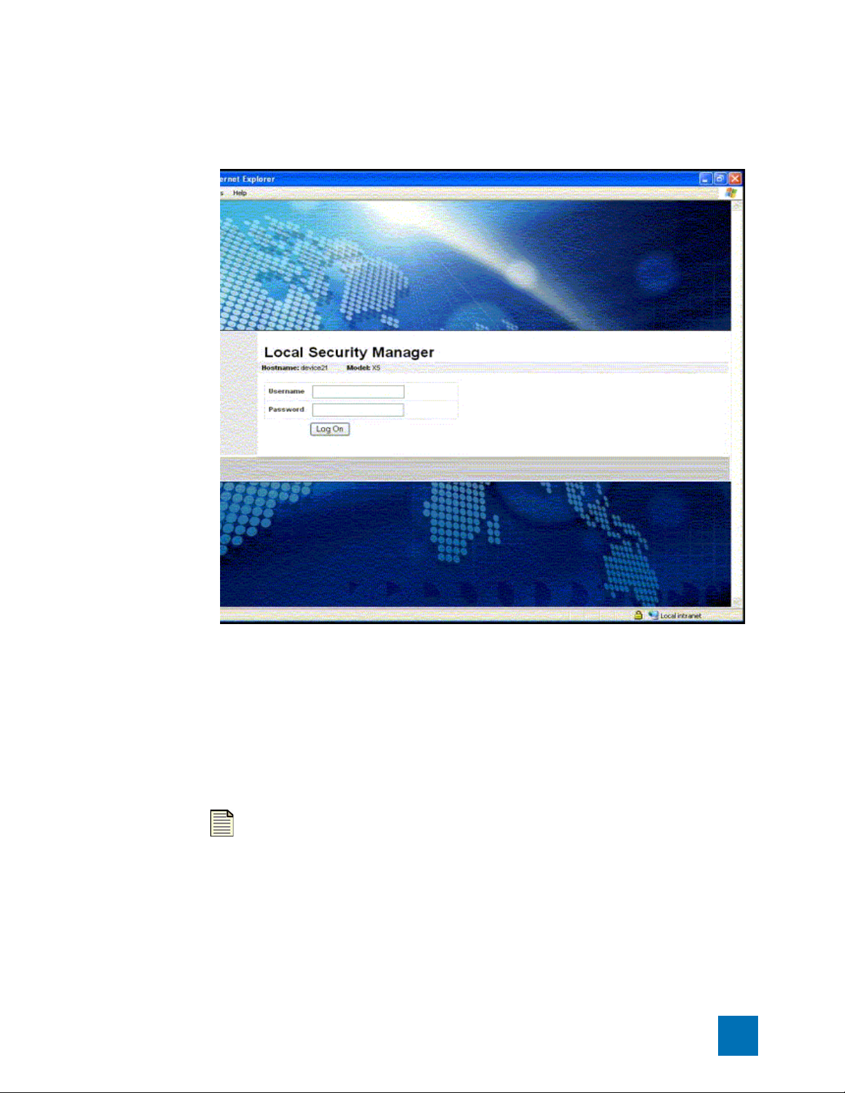
Figure 2–1: LSM Logon Page
Logging In
STEP 2
STEP 3
STEP 4
Enter your Userna me.
Enter your Password
Click Log On.
The LSM validates your account information against the permitted users of the software. If the
information is valid, the LSM software opens. If the account information is not valid, the Login page is
redisplayed.
Note Only 10 Web client and 10 SSH (for CLI) connections are allowed to
connect to a device at once.
X Family LSM User’s Guide V 2.5.1 7
Page 24
Chapter 2 LSM Navigation
LSM Screen Layout
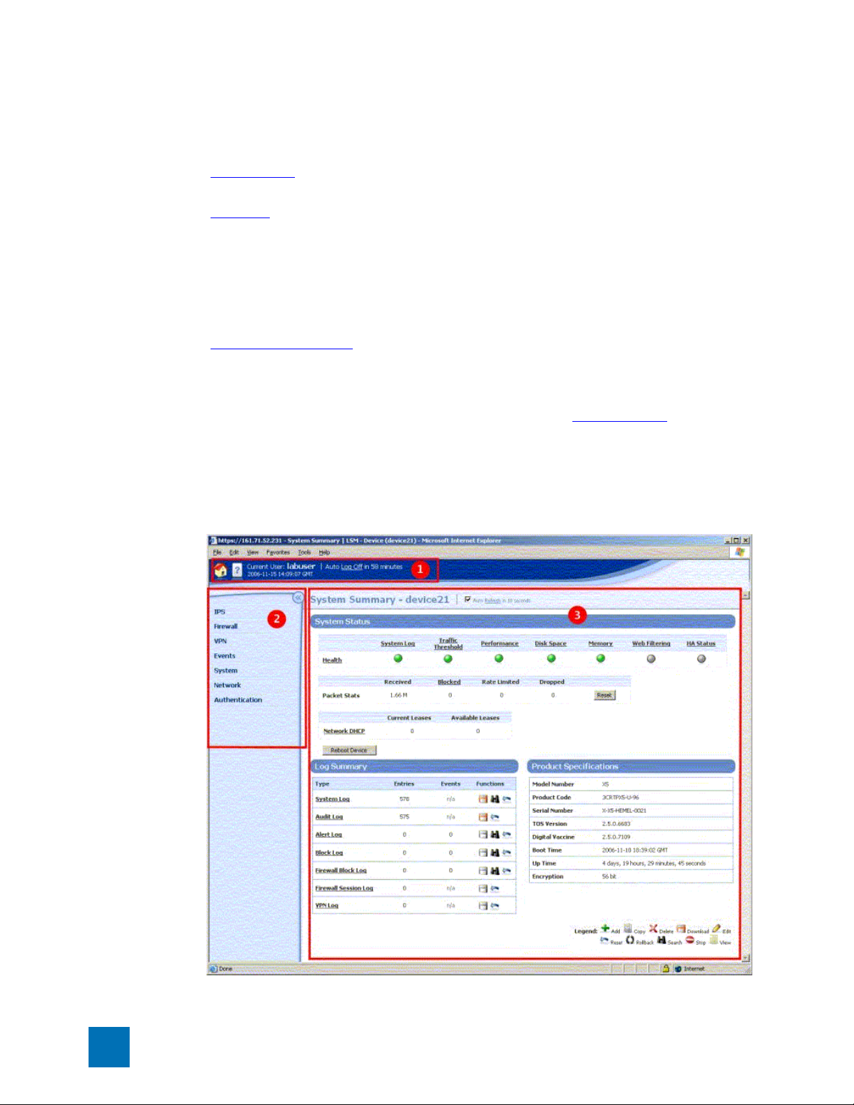
The LSM provides features in two main areas of the browser window:
• Main Menu Bar — Located at the top of the browser window (see item 1 in the figure). This area
provides quick access to the System Summary page, online help, and current user and device status.
• Navigation — Located on the left side bar of the browser window (see item 2 in the figure). The
Navigation bar provides access to the LSM menu functions. To view all the options available for a
main menu item (IPS for example), click the menu label. On an expanded menu, options with a +
indicate that additional sub-menu are available. When you select a menu item, the content and
functionality area displays the content and available options. If you click the << icon in the upper
right corner of the Navigation menu, the menu collapses to provide more screen space for the current
page displayed in the Content and Functionality area. Click >> to re-open the menu.
• Content and Functionality — Located on the right side of the browser window (see item 3 in the
figure). This area displays pages from which you can monitor the device operation and performance,
view current configuration settings, and modify configuration. The content updates when you click a
link in the LSM menu, or when you select buttons or links within a page. Links may display new
content or open dialog boxes. When you first log onto the LSM, the System Summary
automatically displays in this area.
page
Figure 2–2: LSM Screen Layout
8 X Family LSM User’s Guide V 2.5.1
Page 25
LSM Screen Layout
Main Menu Bar
The dark blue bar at the top of the LSM screen provides quick access to basic logon information. The
following table lists the available options in the Main Menu Bar:
Table 2–1: Main Menu Bar Options
Option Description
System Summary To display the System Summary, click the System Summary icon.
For information about this page, see “
page 12.
Online Help To access the X family online help, click the Launch Help Window
icon.
Current User Displays the login name for the current user.
Current date and time Displays the current date and time on the X family device. The date
and time settings on the device are determined by the time
synchronization method and time zone configured for the device.
For details, see “
Time Options” on page 229.
System Summary” on
Auto Log Off To log off of the LSM, click the Log Off link.
For security purposes, LSM sessions have a timeout period. This
timeout period determines how long the LSM can remain idle
before automatically ending the session/ logging off the user. The
default timeout period is 60 minutes. LSM administrators with
super-user access can change the default timeout period from the
Preferences page (Authentication > Preferences). For details, see
“
Preferences” on page 266.
X Family LSM User’s Guide V 2.5.1 9
Page 26
Chapter 2 LSM Navigation
Navigation
You can access the available features of the LSM by selecting an option from the navigation area. The
LSM displays the page you select in the content and functionality area of the browser. Each option list
displays a tier of links and features for maintaining and monitoring the device
The following table lists the available options in the navigation area:
Table 2–2: Navigation Options
Option Description
IPS • Create and manage security profiles used to monitor traffic between security
zones. This includes reviewing category settings, creating filter overrides, and
specifying limits and exceptions for user-specified IP address.
• Create and manage traffic threshold filters, action sets, and ports for IPS
services.
• Manage and configure settings for IPS filters, the Threat Suppression Engine
(TSE), and global Adaptive Filter.
See “Chapter 3‚ “
IPS Filtering” for more information.
Firewall • View and configure settings for the firewall.
• View and configure web filtering for the web filter service and create a custom
filter list to permit or block traffic based on user-specified URLs.
See Chapter 4‚ “
VPN View, configure and manage settings for site-to-site and/or client-to-site VPN
connections. See Chapter 7‚ “
Events • View, download, print, and reset Alert, Audit, Block, and System logs.
• View graphs reporting on traffic flow, traffic-related events, and statistics on
firewall hit counts and triggered filters (attack, rate limit, traffic threshold,
quarantine and adaptive filter).
• Monitor, search, and maintain traffic streams for adaptive filtering, blocked
streams, and rate-limited streams. Manually quarantine an IP address or
release a quarantined IP address.
• View reports on traffic flow, traffic-related events, and statistics on firewall hit
counts and triggered filters (attack, rate limit, traffic threshold, quarantine and
adaptive filter).
• View the status of hardware components, performance (throughput), and
system health.
See Chapter 5‚ “
Firewall” for more information.
VPN” for more information.
Events: Logs, Traffic Streams, Reports” for more information.
System • Configure system controls such as time options, SMS/NMS interaction, and
High Availability.
• Download and install software and Digital Vaccine (filter) updates.
See Chapter 8‚ “
10 X Family LSM User’s Guide V 2.5.1
System” for more information.
Page 27
LSM Screen Layout
Table 2–2: Navigation Options (Continued)
Option Description
Network • Configure network ports, security zones, IP interfaces, IP Address Groups, the
DNS server, the default gateway, routing, and DHCP server information.
• Access network tools for DNS lookup, find network path, traffic capture, ping,
and trace route functionality.
See Chapter 6‚ “
Authentication Create, modify, and manage user accounts. Configure authentication.
See Chapter 9‚ “
Network” for more information.
Authentication” for more information.
Content and Functionality
The LSM displays all data in the central area of the browser window. As you browse and select linked
options from the navigation area, pages display allowing you to review information, configure options,
or search data. Links selected on these pages may display additional pages or dialog boxes depending
on the feature selected.
Title Bar
On each page, you can see the position of the page in the menu hierarchy provided in the title bar. For
example, on the Alert Log page, the menu hierarchy indicates that the page is located off the
EVENTS > LOGS sub-menu. On tabbed menu pages, you can navigate up the hierarchy from the
current location by clicking on the link in the hierarchy listing.
Auto Refresh
Some pages (such as System Summary) automatically refresh themselves periodically.
• To disable the auto refresh function, deselect the Auto Refresh check box.
• To manually refresh: click the Refresh link.
•To reconfigure the Page Refresh Time, see “Preferences” on page 266.
Tabbed Menu Options
Some sub-menu options previously available in the left-hand navigation menu are now accessible as a
tab on the main page for the menu. For example, from the Tools page, the following tabs are available:
DNS Lookup, Find Network Path, Traffic Capture, Ping, and Tr ac e r ou t e.
X Family LSM User’s Guide V 2.5.1 11
Page 28

Chapter 2 LSM Navigation
System Summary
The System Summary page automatically displays when you first log onto the LSM. To redisplay the
System Summary page at any time, click the System Summary icon, in the Main Menu Bar
The System Summary page includes the following:
• System Status — Displays summary information about the device health, packet statistics, and
network DHCP. Also provides access to the Reboot Device function.
• Log Summary — Displays summary information about all the Event Logs.
• Product Specifications — Displays product, version, time, and encryption information.
System Status
Health
The Health section of the Statistics frame displays a color indicator of the hardware health of the
device. For detailed information about each of the health indicators, click on the corresponding link
above the color indicator. The Health section includes indicators for the following components:
.
• System Log
• Traf f ic T hres hold
• Per for ma nce
• Disk Space
• Memory
• Web Fi lt er i ng
• HA Status
The colors indicate the current state of each component:
• Green if there are no problems
• Yellow if there is a major warning
• Red if there is a critical warning
• Grey if the service is disabled
You can set the thresholds for warnings. This defines when the indicator color will change based on the
usage of those components. For more information, see “
Usage” on page 239, and select System > Thresholds in the Navigation area.
If the System Log is other than green, you can click on the indicator to view the error that caused the
condition.
Thresholds to Monitor Memory and Disk
Note When you view the logged error, the indicator resets and changes to green
under System Summary.
12 X Family LSM User’s Guide V 2.5.1
Page 29

System Summary
Packet Stats
The Packet Stats section provides basic traffic statistics including the following:
• Received — Total number of packets received and scanned by the Threat Suppression Engine
• Blocked — Total number of packets that have been blocked by the Threat Suppression Engine
• Rate Limited — The number of packets that matched a filter configured to a permit action set
• Dropped — Total number of packets that have been dropped because they are not properly formed
or formatted
To reset the counters, click the Reset link.
Packet counters provide a snapshot of the traffic going through your network. The packet totals give a
partial account of blocked activity according to the filters. All other filter results affect the packet totals.
Note The counters are not synchronized with each other; packets may be
counted more than once in some situations.
The counters display the amount of packets tracked. If the number is less than 1M, the Packet Statistics
section displays the full amount. If the amount is greater than 999,999 K, the information is
abbreviated with a unit factor. For example, 734,123K would display fully whereas 4,004,876,543
displays as 4.00B. When the number reaches the million and billion mark, the number displays as a
decimal amount with a letter (such as G for gigabytes). The unit factors include, M for mega, G for giga,
and T for tera. To view the full amount, hover your mouse over the displayed amount. A Tool Tip pops
up, displaying the full packet amount.
Network DHCP
The Network DHCP section displays the following information:
• Current Leases
• Available Leases
Reboot Device
To reboot the device, click the Reboot Device link
Log Summary
The Log Summary section displays the number of entries and events for each type of Event Log. In
addition, it allows you to perform functions on those logs.
• System Log
• Audit Log. This log is only available to those with Super User access.
• Alert Log
• Block Log
• Firewall Block Log
• Firewall Session Log
• VPN Log
X Family LSM User’s Guide V 2.5.1 13
Page 30

Chapter 2 LSM Navigation
For more detailed information about these logs, select Events > Logs.
Product Specifications
The Product Specification section displays the following information:
• Model Number — Model number of the device.
• Product Code — The device product code.
• Serial Number — Serial number of the device.
• TOS Version — Version number of the TOS software.
• Digital Vaccine — Version number of the Digital Vaccine.
• Boot Time — Time when the device was last started.
• Up Time — How long the device has been operating continuously.
• Encryption — Current encryption method being used. By default all new X family devices are
supplied with 56-bit DES encryption only. To enable strong encryption functionality (3DES, 128AES, 192-AES, 256-AES), install the correct Strong Encryption Service Pack for your device. You can
download encryption service packs from the TMC Web site.
14 X Family LSM User’s Guide V 2.5.1
Page 31

3
IPS Filtering
LSM Navigation describes the LSM interface, how to log in, and the general sections of the
application.
Overview
The X family provides the TippingPointTM Intrusion Prevention System (IPS) with Digital Vaccine (DV)
filters that can be used to police your network to screen out malicious or unwanted traffic such as:
• Vulnerability Attacks and Exploits
•Worms
•Spyware
• Peer-to-Peer applications
In addition to the Digital Vaccine filters, the IPS function also provides Traffic Threshold filters you
can use to profile and shape network bandwidth.
All IPS filtering occurs inline on traffic that has been permitted through the X family firewall. Filtering is
performed by the Threat Suppression Engine, custom software designed to detect and block a broad
range of attacks at high speed. When a packet matches an IPS filter, the X family device handles the
packets based on the Action configured on the filter. For example, if the action set is Block, then the
packet is dropped. The X family device provides default actions to block or permit traffic with options
to quarantine or rate-limit traffic and to notify users or systems when an action executes. Logging
options are also available so you can review the types of traffic being filtered by the device. You can
customize the default Actions, or create your own based on your network requirements.
A Security Profile defines the traffic to be monitored and the DV filters to be applied. Traffic
monitoring is based on security zone pairs. For example, to create a Security Profile to monitor traffic
coming from the WAN zone to the LAN zone, you select the security zone pair WAN ==> LAN. Then,
you can configure the DV filters to apply to that zone. The security zone pair specifies both the zone
and the traffic direction which allows you to define separate Security Profiles for traffic in and out of a
zone.
X Family LSM User’s Guide V 2.5.1 15
Page 32

Chapter 3 IPS Filtering
The default security profile is set to the ANY ==> ANY security zone pair with all IPS filters
configured with the default Digital Vaccine settings. With the default profile in place, all incoming and
outgoing traffic in any security zone configured on the device is monitored according to the
recommended IPS filter configuration. You can edit the default Security Profile to customize the
security zones that it applies to and create custom filter settings, or create your own Security Profiles as
required.
You can monitor and configure IPS from the IPS menu pages available in the LSM. For additional
information, see the following topics:
• “Using the IPS” on page 16
• “Security Profiles” on page 17
• “IPS Digital Vaccine (DV) Filters” on page 23
• “Traffic Threshold Filters” on page 38
• “Action Sets” on page 44
Note Before creating Security Profiles, verify that the Network and System
configuration on the X family device is set up correctly for your environment. In
particular, you need to configure all required Security Zones before you can create
the Security Profiles to protect them. For details, see “
“
Network” on page 129.
System” on page 217 and
Using the IPS
You can monitor and configure the settings for IPS from the IPS menu pages available in the LSM. The
following menu options are available:
• Security Profiles —View and manage the Security Profiles available on the device, view the security
profile coverage by security zone.
• Traf f ic T hres hold —View, manage and create Traffic Threshold filters to monitor network traffic
levels. These filters can be configured to trigger when traffic is either above or below normal levels.
• Action Sets — View, manage and create actions that define the operations a filter performs when a
traffic match occurs.
• IPS Services —Add and manage non-standard ports supported by the device. Use this feature to
configure additional ports associated with specific applications, services, and protocols to expand
scanning of traffic. When filters scan traffic against the standard ports for listed services, the engine
then accesses and scans traffic against the list of additional ports.
• Preferences —Reset IPS filters to the factory default values, configure timeout, logging, and
congestion threshold settings to manage performance of the Threat Suppression Engine, configure
the Adaptive Filter feature used to protect performance from the effects of over-active filters.
For details on each menu option, see the following topics:
• “Security Profiles” on page 17
• “Traffic Threshold Filters” on page 38
• “Action Sets” on page 44
• “IPS Services” on page 55
• “Preferences” on page 57
16 X Family LSM User’s Guide V 2.5.1
Page 33
Security Profiles
On the X family device, Security Profiles are used to apply DV filter policies. A Security Profile defines
the traffic to be monitored based on security zones (for example, ANY ==> ANY, LAN ==> WAN, or
WAN ==> LAN) and the DV filters to be applied.
A Security Profile consists of the following components:
• Identi fication —Profile name and description.
• Security Zones — Specifies the incoming and outgoing security zones to which the Security Profile
applies.
• IPS Filter Category Settings — Determines the State and Action that applies to all filters within a
given Filter Category group.
• Filter overrides — Configure filter-level settings that override the Category Settings (optional.)
• Global Limits and Exceptions — Configure settings to apply filters differently based on IP address.
You can limit filters to apply only to traffic between a source and destination IP address or address
range, or apply filters to all traffic except the traffic between specified source and destination IP
addresses or address ranges.
When a Security Profile is initially created, the recommended settings for all filter categories are set.
Security Profiles
Default Security Profile
The default security profile is set to the ANY ==> ANY security zone pair with all IPS filters
configured with the default Digital Vaccine settings. With the default profile in place, all incoming and
outgoing traffic in any security zone configured on the device is monitored according to the
recommended DV filter configuration. You can edit the default Security Profile to customize the
security zones that it applies to and create custom filter settings, or create your own Security Profiles as
required. We recommend that you keep the default Security Profile settings configured for the Security
Zone pair ANY ==> ANY. This configuration ensures that all traffic will be inspected by the IPS using
the default Security Profile if the traffic does not match a more specific security zone configuration.
Applying Security Profiles to Traffic
Using IPS, it is possible for a packet to match more than one Security Profile depending how the
security zone pairs are configured within each profile. As a general rule, the X family device will apply
the filtering rules specified in the Security Profile that has the most specific Security Zone pair defined.
To determine specificity, the device always considers the incoming zone first. See the following
examples to see how the device applies filtering rules when a packet matches more than one Security
Profile.
Example 1: Security Profile Zone Configuration
Security Profile Applies To Security Zone Pair
#1 ANY ==> ANY
#2 LAN ==> WAN
In Example 1, a packet going from the LAN zone to the WAN zone matches both Security Profile #1 and
#2. The X family device applies the filtering rules from Security Profile #2 to the packet because the
LAN zone is more specific than the ANY zone.
X Family LSM User’s Guide V 2.5.1 17
Page 34

Chapter 3 IPS Filtering
Example 2: Security Profile Zone Configuration
#4 ANY ==> ANY
#5 ANY ==> WAN
#6 LAN ==> WAN
In Example 2, a packet going from the LAN zone to the WAN zone matches Security Profiles #4, #5 and
#6. However, the X family device applies filtering rules from Security Profile #6 to the packet because
the LAN zone is more specific than the ANY zone.
For additional information on Security Profiles, see the following topics:
• “Managing Security Profiles” on page 19
• “Configuring DV Filters” on page 25
• “Configure Filter Limits/Exceptions based on IP Address” on page 34
Security Profile Applies To Security Zone Pair
18 X Family LSM User’s Guide V 2.5.1
Page 35

Security Profiles
Managing Security Profiles
Use the Security Profiles page (IPS > Security Profiles) to create and manage the Security Profiles
used to apply IPS filtering to security zone traffic.
Figure 3–1: Security Profiles Page
The following table provides a summary of tasks available to configure and manage security profiles
from the Security Profiles menu pages in the LSM.
Table 3–1: Security Profile Tasks
Ta sk Procedure
View all Security
Profiles
Create a Security Profile From the LSM menu, select IPS > Security Profiles. On the
Edit a Security Profile From the LSM menu, select IPS > Security Profiles. On the
Delete a Security Profile
Change category
settings for a group of
filters
From the LSM menu, select IPS > Security Profiles. Then, click a
Security Profile name to open the profile. You can view a list of the
Security Profiles as well as a listing that shows which Security
Profiles provide DV filtering for the different Security Zones
configured on the device.
Note You cannot delete the default Security Profile.
Security Profile page, click Create.
Security Profile page, click Edit.
On the Security Profiles page, click . When you delete the profile,
all the global and filter level settings are deleted.
On the Edit Security Profile page in the Profile Details (Advanced)
section, change the State and Acti on setting for the category you
want to modify. Then, Save the updated profile.
X Family LSM User’s Guide V 2.5.1 19
Page 36

Chapter 3 IPS Filtering
Table 3–1: Security Profile Tasks (Continued)
Ta sk Procedure
Override global filter
settings (create filter
level settings)
On the Edit Security Profile page in the Profile Details (Advanced)
Filters section, click Search Filters. On the Search Filters page,
locate the filter to override. Click the + icon to add the filter to the
Security Profile. Then, edit the filter to customize the settings.
Restore filter to global
category settings
On the Edit Security Profile page in the Profile Details (Advanced)
Filters section, locate the filter override to delete. Then, click .
(Delete filter override)
Edit Port Scan/Host
Sweep Filters
The Port Scan/Host Sweep filters are a special type of filter used to
protect the network against Port Scan/Host Sweep attacks. These
filters can only be applied to Security Zones that include physical
ports. For additional information on these filters, see “
Host Sweep Filters” on page 35.
For additional information, see the following topics:
• “Security Profile Details” on page 20
• “Create a Security Profile” on page 21
• “Edit a Security Profile” on page 22
• “View DV Filters” on page 26
• “Edit DV Filter Category Settings” on page 29
• “Port Scan/Host Sweep Filters” on page 35
Port Scan/
Security Profile Details
The following table describes the information available on the Security Profiles page.
Table 3–2: Security Profile Details
Parameter Description
Current Profiles: This section lists all the Security Profiles currently configured on the X family
device.
Profile Name The name assigned to the Security Profile. The Default Security Profile is
pre-configured on the device. You can customize this profile to add Security
Zone pairs or modify global and individual filter settings, but you cannot
delete or rename this profile.
Description Displays the description entered for the Security Profile if any exists.
Function(s) The functions available to manage Security Profiles:
• Edit the Security Profile to configure security zones, Category Settings,
filter overrides, or global limits and exceptions
• Delete the Security Profile.
20 X Family LSM User’s Guide V 2.5.1
Page 37

Security Profiles
Table 3–2: Security Profile Details (Continued)
Parameter Description
Security Zones: This section lists all the security zone pairs that are currently protected by a
Security Profile.
Note If a Traffic Threshold has been configured with a Security Zone pair that is not
protected by a Security Profile, the pair will be listed in the table in red along with the
following message:
No security profile is assigned to the security zones. Traffic
will NOT be inspected by the IPS
.
To correct the error, add the security zone pair to an existing Security Profile, or create a
new Profile to protect it.
Incoming The Security Zone that is the traffic source
Outgoing The Security Zone that is the traffic destination
Security Profile The name of the Security Zone configured on the device
For additional information, see the following topics:
• “Create a Security Profile” on page 21
• “Edit a Security Profile” on page 22
• “View DV Filters” on page 26
• “Edit DV Filter Category Settings” on page 29
Create a Security Profile
STEP 1
On the LSM menu, select IPS > Security Profiles. Then, click the Create Security Profile
button.
STEP 2
On the Create Security Profiles page, click the (edit) icon to edit the desired security profile.
STEP 3
In the Security Zones section, specify the security zone pairs for the Security Profile:
STEP A
STEP B
Select the Incoming and Outgoing Security Zone.
Click Add to table.
Repeat this process until you have added all the required security zone pairs.
Note For additional information about setting up the Security
Zones, see “
Security Zone Configuration” on page 135.
STEP 4
Review or configure advanced configuration options. If the advanced options are not visible,
click Show Advanced Options. In the Profile Details (Advanced) section in the Category
X Family LSM User’s Guide V 2.5.1 21
Page 38

Chapter 3 IPS Filtering
Settings table, change the global State or Action for a filter Category Group if required. For
more detailed instructions, see
“Edit Category Settings for a Filter Group” on page 30.
STEP 5
Click Create.
After you create the Security Profile, you can edit the Security Profile and perform additional
advanced configuration to create filter overrides and specify global limits and exceptions.
Edit a Security Profile
STEP 1
STEP 2
On the LSM menu, select IPS > Security Profiles.
On the Create Security Profiles page, click the (edit) icon to edit the desired security profile.
STEP 3
In the Security Zones section, modify the security zone pair configuration, if necessary.
STEP A
STEP B
Select the Incoming and Outgoing Security Zone.
Click Add to table.
Repeat this process until you have added all the required security zone pairs.
STEP 4
STEP C
Review or configure advanced configuration options. If the advanced options are not visible,
Click to delete a security zone.
click Show Advanced Options. Do any of the following as needed:
•In the Profile Details (Advanced) section in the Category Settings table, change the
global State or Action for a filter Category Group if required. For more detailed instructions,
see “
Edit Category Settings for a Filter Group” on page 30.
• To review filters or add a filter to the Security Profile for customization, locate the filter
using the Search Filters button or View all filters link. For details, see “
Filter Settings” on page 32.
• Configure global IP address limits or exceptions if required. For details, see “
Global IP address Limits and Exceptions” on page 34.
Edit Individual
Configure
STEP 5
Click Save to update the Security Profile.
For additional information, see the following topics:
• “View DV Filters” on page 26
• “Edit DV Filter Category Settings” on page 29
• “Port Scan/Host Sweep Filters” on page 35
22 X Family LSM User’s Guide V 2.5.1
Page 39

IPS Digital Vaccine (DV) Filters
TippingPoint IPS Digital Vaccine (DV) Filters are used to monitor traffic passing between network
security zones. Based on the Security Profiles configured on the device, the X family applies the filters
to traffic passing between network security zones. Each Security Profile has its own filter settings.
Within a Security Profile, you can modify the filter (recommended) settings for a filter category and, if
necessary, customize individual filters based on your network environment and security needs. The
following sections provide an overview of the DV filters and the components used to configure them:
• “About the Digital Vaccine Package” on page 23
• “Filter Components” on page 24
• “Categories and Category Settings” on page 24
Categories and category settings are used to configure global settings for all filters within a specified
category group.
• “Filter Override Settings” on page 25
Filter settings are used to override the global settings for individual filters within a category group.
About the Digital Vaccine Package
DV filters are contained in a Digital Vaccine (DV) package. All X family devices have a DV package
installed and configured to provide out-of-the-box IPS protection for the network. After setting up the
X family device, you can customize the DV filter configuration through the LSM.
IPS Digital Vaccine (DV) Filters
The filters within the DV package are developed to protect the network from specific exploits as well as
potential attack permutations to address Zero-Day threats. These filters include traffic anomaly filters
and vulnerability-based filters. Vulnerability-based filters are designed to protect the network from an
attack that takes advantage of a weakness in application software. For viruses that are not based on a
specific vulnerability in software, the DV provides signature filters. We deliver weekly Digital Vaccine
updates which can be automatically installed on the device (System > Update). If a critical
vulnerability or threat is discovered, Digital Vaccine Updates are immediately distributed to customers.
TIP
In addition to providing a download location for Digital Vaccine packages,
the TMC also provides DV product documentation that includes more detailed
information about the filters included in the DV package, filter updates, and other
related information.
X Family LSM User’s Guide V 2.5.1 23
Page 40

Chapter 3 IPS Filtering
Filter Components
IPS filters have the following components which determine the identity the filter type, global and
customized settings, and how the device will respond when the Threat Suppression Engine finds traffic
matching the filter:
• Category — defines the type of network protection provided by the filter. The category is also used
to locate the filter in the LSM and to control the global filter settings using the Category Setting
configuration.
• Action set — defines the actions that execute when the filter is matched.
• Adaptive Filter Configuration State — allows you to override the global Adaptive Filter
configuration settings so that the filter is not affected by adaptive filtering (see
Configuration” on page 60 for additional information)
• State — Indicates if the filter is enabled, disabled, or invalid. If the filter is disabled, the Threat
Suppression Engine does not use the filter to evaluate traffic.
Categories and Category Settings
Categories and category settings are used to configure global settings for all filters within a specified
category group.
DV Filters are organized into Categories and groups based on the type of protection provided:
“Adaptive Filter
• Application Protection Filters — defend against known exploits and exploits that may take
advantage of known vulnerabilities targeting applications and operating systems. This filter type
includes the following sub-categories: Exploits, Identity Theft, Reconnaissance (includes Port Scan/
Host Sweep filters), Security Policy, Spyware, Virus, and Vulnerabilities.
• Infrastructure Protection Filters — protect network bandwidth and network infrastructure
elements such as routers and firewalls from attack by using protocols and detecting statistical
anomalies. These filter types includes the sub-categories Network Equipment and Traffic
Normalization.
• Performance Protection Filters —block or rate-limit traffic from applications that can consume
excessive bandwidth, leaving network resources available for use by key applications. This filter type
includes the following sub-categories: IM, P2P, and Streaming Media.
These Categories are used to locate filters. Category Settings are used to assign global configuration
settings to filters within a category. For example, if you want don’t want to use any filters to monitor
P2P traffic, you can the disable the P2P group in the Performance Protection category. You can
configure the following global parameters:
• State — determines whether filters within the Category are enabled or disabled. If a category is
disabled, all filters in the Category are disabled.
• Action Set — determines the action set that filters within a Category will execute when a filter
match occurs. If the Recommended action set is configured, filters within the category are configured
with the settings recommended by the Digital Vaccine team, the group can have different settings.
For the best system performance, we recommend that you use global Category Settings and the
Recommended action set for all DV filters. However, in some cases, you may need to override the
category settings and recommended action for individual filters due to specific network requirements,
or in cases where the recommended settings for a filter interact poorly with your network.
24 X Family LSM User’s Guide V 2.5.1
Page 41

IPS Digital Vaccine (DV) Filters
Filter Override Settings
For the best system performance, we recommend that you use global Category Settings and the
Recommended action set for all DV filters. However, in some cases, you may need to override the
category settings and recommended action for individual filters due to specific network requirements,
or in cases where the recommended settings for a filter interact poorly with your network.
Filter override settings specify custom settings to be applied to the filter in the Security Profile. Once a
filter has been customized, it is not affected by the global Category Settings that specify the filter State
and Action. For details, see “
Edit Individual Filter Settings” on page 32.
Configuring DV Filters
You configure filters separately for each Security Profile configured on the X family device. When a
profile is initially created, all filters are set to the default Category Settings. You can change the
Category Settings for filters or edit individual filters from the Edit Security Profile page in the LSM.
Because of the large number of DV filters available on the device, the LSM provides a search interface to
view and edit filters. For instructions on using this interface and on editing filters, see the following
topics:
• “View DV Filters” on page 26
• “Edit DV Filter Category Settings” on page 29
o
“Edit Category Settings for a Filter Group” on page 30
o
“Edit Individual Filter Settings” on page 32
o
“Configure Filter Limits/Exceptions based on IP Address” on page 34
o
“Edit a Port Scan/Host Sweep Filter” on page 36
• “Reset an Individual Filter” on page 35
X Family LSM User’s Guide V 2.5.1 25
Page 42

Chapter 3 IPS Filtering
View DV Filters
You can view and manage filters configured for a Security Profile using either the Filters and Filter
Search pages. Both pages can be accessed from the Advanced Options Filters section of the Security
Profile pages.
• To access the Filters page, use the View all filters link
• To access the Filter Search page, click Search Filters
The following figure shows the Filters page:
Figure 3–2: IPS: Filters Page with Search
You can complete the following tasks from these pages:
• View current filters
• Sort the filter list
• Locate a filter or group of filters
• Add a filter to the filter override list for the current Security Profile
• View the filter description page which includes information about the filter, recommended settings,
and the current filter state
• Add or remove a filter from selected Security Profiles
For additional information, see the following topics:
• “Filter Search” on page 27
• “Filters List (All Filters)” on page 27
• “Reset an Individual Filter” on page 35
• “Port Scan/Host Sweep Filters” on page 35
26 X Family LSM User’s Guide V 2.5.1
Page 43

IPS Digital Vaccine (DV) Filters
Filter Search
Filter search provides options to view all filters or only those matching user-specified search criteria.
You can access the Filter Search page by clicking the Search Filters button when you are editing a
Security Profile (IPS > Security Profiles, then edit a profile).
You can sort filter search results by filter name, control type, action, or state by clicking a column
heading in the Filters List table. The search is a string search is is not case sensitive.
The following table describes the available search criteria that can be configured:
Table 3–3: Search Filter Criteria Parameters
Parameter Description
Keywords Type a word or phrase to search for in the filter names. The keyword Filter
Search is a string search, not a boolean search. You can search for a specific
filter number, or for a specific substring in the filter name. If you enter more
than one word, the search will look for the exact phrase entered, not a
combination of words.For example, if you enter “ICMP reply” the search will
not return a filter whose description is “ICMP: Echo Reply.”
Include Description Check this option to search for the specified keyword(s) in the filter
descriptions, as well as in the filter names.
Filter # Search by filter number, type the filter number in this field.
Filter State Search by current operating state, select from the following: Any, Disabled,
or Enabled.
Filter Control Search for filters configured with Category Settings or filters that have been
customize (override).
Categories Search by IPS filter Category group. Selection list includes all groups in the
Application Protection, Infrastructure Protection, and Performance
Protection categories.
Action Set Search by Action Set assigned to filter. The selection list includes all the
default and custom Action Sets configured on the device.
Protocol Search by transport protocol that the filter applies to: ANY, ICMP, TCP, and
UDP
Severity Search by the Severity Level assigned to the filter.
For details on performing a filter search see the following topics:
• “View Filters with Recommended (Default) Settings” on page 29
• “View Filter Overrides and Custom Settings” on page 29
Filters List (All Filters)
The Filters List page provides a listing of all filters configured for the Security Profile. You can access
the page by selecting the View all filters link when you are editing the Security Profile. Because of the
large number of filters, it may take some time for the device to display the page.
X Family LSM User’s Guide V 2.5.1 27
Page 44

Chapter 3 IPS Filtering
Filter List Details
The following table describes the information and functions available on the Filters List page.
Table 3–4: Filter List Details
Search Interface For details on the search criteria fields, see “Search Filter Criteria
Check Box Use the check box for a filter entry to select it for editing. After checking the
Filter Name The name of the filter. The name contains the filter number and additional
Parameter Description
Parameters” on page 27.
desired filters, use the Add Selected Filters button to add the filters to the
Security Profile so you can edit them.
If a filter entry has no check box, that filter has already been added to the
Security Profile. You can manage these filters from the Security Profiles page
Filters table.
information relating to the protocol the filter applies and/or other
descriptive information about the purpose of the filter (0079: ICMP:Echo
Reply). These names are assigned by the Digital Vaccine team.
To view filter information, click the name of the filter.
Control Indicates whether the filter configuration is:
• Category Settings — uses the global Category Settings configured for the
filter’s category.
To view the Category and Category Group for filter, click the filter name.
• Filter — uses custom settings configured from the Security Profile page.
You can manage customized filters from the Filters table on the Security
Profile page.
Action Set Indicates the action set currently assigned to the filter. If the filter uses
Category Settings and the Action Set is recommended, the Action field lists
Disabled to indicate that the filter is under the control of the default
configuration.
If the filter has an override, the Action selected in the override is displayed.
State Indicates whether the filter is enabled (in use) or disabled.
Function(s) Available functions for the filter:
• Add to Security Profile so you can edit the filter settings.
If the filter has been overridden, the Add function is not available. You can
edit the filter settings from the Filter Override list on the Security Profile
page.
28 X Family LSM User’s Guide V 2.5.1
Page 45

IPS Digital Vaccine (DV) Filters
For details on viewing filters on the Filter List page, see the following topics:
• “View Filters with Recommended (Default) Settings” on page 29
• “View Filter Overrides and Custom Settings” on page 29
View Filters with Recommended (Default) Settings
STEP 1
STEP 2
STEP 3
On the LSM menu, select IPS > Security Profiles.
On the Security Profiles page, click the (edit) icon to edit the desired security profile.
On the Edit Security Profile page, if the Profile Details (Advanced) table is not visible, click
Show Advanced Options.
STEP 4
In the Profile Details (Advanced) table, scroll down to the Filters section. You can click
either View all filters or Search Filters.
• View all filters displays the Filters page. Because of the large number of filters, this action
may take some time to execute.
If you select this option, the Search Filters page displays a list of the available IPS filters. You
can sort the filters by filter name, control type, action, or state by clicking the appropriate
column heading in the Filters List table. To specify new search criteria, use the search
interface available at the top of the page.
• Search Filters displays the Search Filters page so you can specify filter search criteria and
perform the search.
If you select this option, select the desired Search criteria. Then click Search. Note that the
Search facility performs string searches. If you select Search Filters, the Search Filters page
displays with only the search interface displayed. To locate filters, specify one or more
search parameters. Then, click Search. Note that the search is a string search.
View Filter Overrides and Custom Settings
STEP 1
STEP 2
STEP 3
On the LSM menu, select IPS > Security Profiles.
On the Security Profiles page, click the Profile Name you want to edit.
On the Edit Security Profile page, if the Profile Details (Advanced) table is not visible, click
Show Advanced Options.
STEP 4
In the Profile Details (Advanced) table, scroll down to the Filters section.
In the Filters section, the table lists all filters that have been added to the Profile.
STEP 5
To view and/or edit a filter, click the Filter Name.
If you want to remove the filter override and return the filter to its default, recommended
settings, click the Delete icon.
Edit DV Filter Category Settings
By default, a Security Profile uses the Category Settings for all filters available in the Digital Vaccine
package. In some cases you may not need a particular filter or category of filters. For example, you may
want to disable filters that protect a particular type of web server against attack if that server is not
X Family LSM User’s Guide V 2.5.1 29
Page 46

Chapter 3 IPS Filtering
installed on your network. From the LSM, you can modify the filter configuration for a Security Profile
by category or by changing individual filter settings. You can make the following types of changes:
• Edit a Filter Category Group to enable/disable all filters in the group or change the assigned action for
all filters in the group.
• Edit an individual filter or group of filters to modify the following settings: State, Action, Adaptive
Filter Configuration State, Exceptions.
When you edit a filter, the changes only affect the Security Profile in which you make the edits. This
allows you to have different filter configurations for different Security Zones.
For details on editing filters, see the following topics:
• “Edit Category Settings for a Filter Group” on page 30
• “Edit Individual Filter Settings” on page 32
• “Edit a Port Scan/Host Sweep Filter” on page 36
Note If the category setting is enabled and you disable the filter, the filter may
still display as enabled.
Edit Category Settings for a Filter Group
Note When you change the Category Settings for a group of filters, the settings
will not affect any filters that have been customized (overridden). Filters that have
been customized display on the Edit Security Profiles page in the Filters section.
On the Filters List page, these filters are listed with Control = Filter.
STEP 1
STEP 2
From the LSM menu, click Security Profiles.
On the Security Profiles page in the Current Profiles table, click the pencil icon for the Security Profile you want to change.
STEP 3
On the Edit Security Profile page in the Advanced Options section, locate the Filter Category
group in the Category Settings table.
30 X Family LSM User’s Guide V 2.5.1
Page 47

IPS Digital Vaccine (DV) Filters
The following figure shows the Category Settings table.
Figure 3–3: Edit Security Profile Page - Advanced Options - Category Settings
Click Show Advanced Options if the Advanced Options table is not displayed.
STEP 4
Modify the settings as required:
•In the State field for the Category group, clear the check box to disable all filters in the
group, or check it to enable all filters in the group.
•In the Action field, select the Action Set to be used for all filters in the group.
The Recommended Action Set is the system default for all category groups. If this action is
selected, each filter in the group is configured with the recommended settings. Filters
within the group may have different settings for State and Act ion.
The following action set selections are available for each Filter Category:
o
For all Application Protection filters, the selection list includes all available actions sets.
o
For Infrastructure Protection filters, the selection list includes all available actions sets.
o
For Performance Protection filters, the selection list includes all available block action
sets.
STEP 5
After making the desired changes, click Save (at the bottom of the Security Profile page).
Edit Individual Filters to Override Category Settings
For the best system performance, we recommend that you use global Category Settings and the
Recommended action set for all DV filters. However, in some cases, you may need to override the
category settings and recommended action for individual filters due to specific network requirements,
or in cases where the recommended settings for a filter interact poorly with your network.
Filter override settings specify custom settings to be applied to the filter in the Security Profile. Once a
filter has been customized, it is not affected by the global Category Settings that apply to all other filters
in the category group. For details, see “
Edit Individual Filter Settings” on page 32.
X Family LSM User’s Guide V 2.5.1 31
Page 48

Chapter 3 IPS Filtering
Edit Individual Filter Settings
Note These instructions are for editing all Application Protection, Infrastructure
Protection, and Performance Protection filters with the exception of the Port Scan/
Host Sweep filters available in the Application Protection: Reconnaissance
category. For details on Port Scan/Host Sweep filters, see “
Port Scan/Host Sweep
Filters” on page 35.
STEP 1
STEP 2
STEP 3
STEP 4
STEP 5
From the LSM menu, click Security Profiles.
On the Security Profiles page in the Current Profiles table, click the pencil icon for the Security Profile you want to change.
On the Edit Security Profile page in the Advanced Options section, locate the Filters table.
In the Filters table, find the filters that you want to edit. Do one of the following:
•Click Search Filters. Then, on the Search Filters page, specify the search criteria. Click
Search to display the filter search results.
•Click View all filters to display the Filters page with all IPS filters available.
Because of the large number of IPS filters, this operation may take a few moments to
complete.
To view filter details including filter name description and default settings, click the filter
name to display the details on the View Filter page.
32 X Family LSM User’s Guide V 2.5.1
Page 49

IPS Digital Vaccine (DV) Filters
On the View Filter page, you can also add or remove the filter from Security Profiles using the
check boxes in the Security Profiles table. After making changes, click Save.
STEP 6
STEP 7
STEP 8
In the Filters List table, select the filter or filters to edit:
• To select a single filter, click to add the filter to the Security Profile.
• To select multiple filters, select the check box for each filter. Then, click the Add Selected
Filters button at the bottom of the Filters page.
The Security Profiles page displays with the selected filters in the Advanced Options - Filters
table as shown in the following figure.
To edit the filter settings, click the filter name, or the pencil icon.
On the Edit Filter page in the Action/State section, select Use Category Settings or Over-
ride. If you select Override to use a different action set for the filter, do the following:
STEP A
Select the Override radio button in the Parameters section.
STEP 9
STEP 10
STEP 11
STEP B
Check Enabled to enable the filter, or clear the check box if you want to disable the
filter.
STEP C
Choose an Ac tio n from the drop-down list.
If the action for the filter is Recommended and you do not change it, the filter may
remain disabled even when you select the Enabled check box. This happens
because the recommended setting for the filter state is disabled. To enable a filter
configured in this manner, you must change the action from Recommended to
another option.
Optionally, set adaptive filter settings for flow control. In the Adaptive Filter Configuration
State section, select one of the following:
• Use adaptive configuration settings — Applies the global adaptive filter settings
• Do not apply adaptive configuration settings to this filter — Removes any global
adaptive filter settings for this filter
Optionally, define IP address exceptions for the filter. For details, see “Configure Filter Limits/
Exceptions based on IP Address” on page 34.
Click Save.
X Family LSM User’s Guide V 2.5.1 33
Page 50

Chapter 3 IPS Filtering
Configure Filter Limits/Exceptions based on IP Address
Limits and exceptions allow you to configure the device so that the filters in a Security Profile can be
applied differently based on IP address. For example, you can specify a limit setting so that filters only
apply to specified source and destination IP addresses or address ranges. You can configure the
following limit and exceptions from the LSM:
• Filter Exceptions (specific)— Allow traffic that would normally trigger a filter to pass between
specific addresses or address ranges without triggering the filter. Configured from the Filter Edit
page, these exceptions apply only to the filter on which they are configured.
• Limit Filter to IP Addresses (global) —Only apply filters to traffic between specified source and
destination IP address pairs. You can configure IP address limits that apply to all the following filter
types: Application Protection, Traffic Normalization, and Network Equipment Protection filters. You
can configure separate limits that apply only to Performance Protection filters.
• Exceptions (global) — Exclude traffic between specified source and destination IP address pairs.
You can configure exceptions for the following filter types: Application Protection, Traffic
Normalization, Network Equipment Protection, and Performance Protection filters. These exceptions
are global for all specified filters.
If a filter has both global and filter-level exception settings, the Threat Suppression Engine uses the
filter-level settings to determine how to apply the filter.
The following sections describe the procedures to configure and delete global limits and exceptions
from the Security Profile page.
• “Configure Global IP address Limits and Exceptions” on page 34
• “Delete a Global Limit/Exception Setting” on page 35
• Configure filter-level exceptions: “Edit Individual Filter Settings” on page 32
Configure Global IP address Limits and Exceptions
STEP 1
From LSM menu, click IPS. Then, edit the Security Profile where you want to modify limit/
exception settings.
STEP 2
On the Edit Security Profile page in the Advanced Options section, scroll down to the Limits/Exceptions table.
Click Show Advanced Options if the Advanced Options table is not displayed.
STEP 3
In the Limits/Exceptions section, specify the Application Protection Filter Exclusives (lim-
its) for Application Protection, Traffic Normalization, and Network Protection filters:
STEP A
Enter the Source Address.
Source and Destination IP Addresses can be entered in CIDR format, as “any” or as
*.
STEP B
STEP C
STEP D
34 X Family LSM User’s Guide V 2.5.1
Enter the Destination Address.
Click add to table below.
Repeat this process for each IP address exception required.
Page 51

IPS Digital Vaccine (DV) Filters
STEP 4
In the Application Protection Filter Setting Exceptions section, specify the IP address
exceptions for Application Protection, Traffic Normalization, Network Equipment Protection
and Performance Protection filters.
STEP 5
In the Performance Protection Filter Settings section, specify IP address limits for Performance Protection filters.
STEP 6
Click Apply.
Delete a Global Limit/Exception Setting
STEP 1
From LSM menu, click IPS. Then, edit the Security Profile where you want to modify limit/
exception settings.
STEP 2
On the Edit Security Profile page in the Advanced Options section, scroll down to the Limits/Exceptions table.
Click Show Advanced Options if the Advanced Options table is not displayed.
STEP 3
Review the global limit and exception address entries. Click to delete an entry.
To delete a filter-level exception, edit the filter. For details, see “Edit Individual Filter Settings”
on page 32
STEP 4
Click Apply.
Reset an Individual Filter
If you have created a filter override in a Security Profile, you can restore the filter to its default settings
by deleting the Filter from the Security Profile Filters table.
You can also reset all filters to their factory default settings from the IPS Preferences page. If you do
this, all the filters will be set to their recommended state and all action sets, rate limits, and thresholds
(other than defaults) will be deleted. You will also lose the Security Profiles you have created along with
any custom settings configured on the default Security Profile. For details, see “
page 57.
Delete a Filter Override
STEP 1
STEP 2
From the LSM menu, click Security Profiles.
On the Security Profiles page in the Current Profiles table, click Profile Name for the profile
you want to change.
STEP 3
STEP 4
On the Edit Security Profile page in the Advanced Options section, locate the Filters table.
In the Filters table, find the entry for the filter override you want to remove. Then, click .
The filter is restored to the recommended settings for the category it belongs to.
Reset Filters” on
Port Scan/Host Sweep Filters
A port scan attack scans a host looking for any open ports that can be used to infiltrate the network. A
host sweep scans multiple hosts on the network looking for a specific listening port that can be used to
infiltrate the network.
X Family LSM User’s Guide V 2.5.1 35
Page 52

Chapter 3 IPS Filtering
The Port Scan/Host Sweep Filters (Filter numbers 7000- 7004) available in the Application Protection
Category - Reconnaissance group are designed to protect the network against these types of attacks.
These filters monitor the rate of connections generated by hosts on the network. The filter triggers
when the connection rate during a specified interval goes above a given threshold.
The following figure shows the Port Scan/Host Sweep Filters added to the Security Profile for editing.
Figure 3–4: Security Profile: Port Scan/Host Sweep Filter Overrides
The Port Scan/Host Sweep Attack filters can only be used to monitor traffic on Security Zones that
include physical ports. That is, you cannot run Port Scan/Host Sweep filters on VLANs or zones
configured with a Virtual Server.
In the Category Settings, all Port Scan/Hosts Sweep filters are disabled. To apply these filters to the
Security Profile, enable the filters, tune the threshold and timeout interval settings, and assign an action
set based on your network requirements. Because the Recommended setting for Port Scan Host/Sweep
filters is disabled, you have to assign a specific action to the filter to enable it.
Filter Tuning
You can tune the sensitivity of Port Scan/Host Sweep filters by adjusting their Time out and Threshold
parameters. The timeout value is used in combination with the threshold value to determine whether
or not an alert is sent.
For example, if the time interval is 300 seconds (5 minutes) and the connection threshold is 100 hits,
then the filter is triggered every time the rate of connections exceeds 100, or exceeds a multiple of the
threshold (101, 201, 301...) within the 300 second (five minute) time period.
The filters support any of the configured action sets available on the device. You can also configure IP
address exceptions.
Edit a Port Scan/Host Sweep Filter
STEP 1
From the LSM menu, click Security Profiles. Then, edit the Security Profile on which you
want to provide Port Scan/Host Sweep filter protection.
The Security Profile must contain zones that have physical ports.
STEP 2
36 X Family LSM User’s Guide V 2.5.1
On the Security Profile page, scroll down to the Advanced Options, Filters section.
Page 53

IPS Digital Vaccine (DV) Filters
STEP 3
STEP 4
STEP 5
STEP 6
Locate the Port Scan/Host Sweep filters:
STEP A
STEP B
STEP C
STEP D
STEP E
Click Search Filters. Then, on the Filter Search page, specify the search criteria:
In the Categories selection list, click Reconnaissance.
In the Severity selection list, click Low.
Click Search.
In the Filters List with the search results, click the >> page control button to go to
the last page of the results.
To add the Port Scan/Host Sweep filters to the Security Profile for editing, do one of the following:
• To add an individual filter, click the Add icon in the Functions column for that filter.
• To add multiple filters, check each filter. Then, click Add Selected Filters.
On the Edit Security Profile page in the Filters section, click the Filter Name to edit the settings.
In the Ac tion/State section, select Use Category Settings or Override. If you select Over-
ride to use a different action set for the filter, do the following:
STEP A
STEP B
Select the Override radio button in the Parameters section.
Check the Enabled check box.
STEP 7
STEP 8
STEP 9
STEP 10
STEP C
Choose an Ac tio n from the drop-down list.
Optionally, you can set adaptive filter settings for flow control. In the Adaptive Filter
Configuration State section, select one of the following:
• Use adaptive configuration settings — Applies the global adaptive filter settings
• Do not apply adaptive configuration settings to this filter — The filter will not be
monitored by the Adaptive Filter mechanism
In the Scan/Sweep Parameters section, do the following:
STEP A
STEP B
Enter the number of seconds for the Timeout.
Enter the number of hits allowed for the Threshold.
Optionally, you can add exceptions to the filter so that the filter will not be used to monitor
traffic from specified IP addresses. In the Exceptions section, do the following:
STEP A
STEP B
STEP C
Enter the Source Address.
Enter the Destination Address.
Click add to the table below.
Click Save.
X Family LSM User’s Guide V 2.5.1 37
Page 54

Chapter 3 IPS Filtering
Traffic Threshold Filters
Note The default X family configuration does not include any Traffic Threshold
filters. You must create them based on your network requirements.
Traffic threshold filters alert you and the device when network traffic varies from the norm. The device
determines normal traffic patterns based on the network statistics over time. You can set four types of
thresholds for each filter:
• major increase — Traffic is greatly over the set threshold.
• minor increase — Traffic is slightly over the set threshold.
• minor decrease — Traffic is slightly below the set threshold.
• major decrease — Traffic is greatly under the set threshold.
Thresholds are expressed as a “% of normal” traffic. For example, a threshold of 150% would fire if
traffic exceeded the “normal” amount by 50%. A threshold of 60% would fire if the level of traffic
dropped by 40% from “normal” amount of traffic.
Note Network traffic rates are inherently erratic and can vary as much as 50%
above or below the normal level on a regular basis. When you set up Traffic
Threshold filters, avoid setting small variation percentages for minor and major
thresholds to prevent the Traffic Threshold filter from triggering too often.
You can configure an action set for each threshold level configured for the Traffic Threshold filter.
When the filter triggers, the device executes the action specified for the threshold setting that triggered
the filter. You can also configure traffic thresholds to monitor traffic on the network without taking any
action. All traffic threshold activity is recorded in the Traffic Threshold report (Events > Reports >
Traf f ic T hres hold ).
Thresholds trigger when the traffic flow is above the Above Normal threshold, or below the Below
Normal threshold by the set amounts. When traffic exceeds a threshold and returns to normal levels,
the device executes the action specified for the threshold that triggered the filter and generates an alert.
These alerts inform you of the triggered filter, when the thresholds are exceeded and return to normal,
and the exceeded amount. After the filter triggers, you must reset it to re-establish it for use in the
device. The filter is not disabled, but it does require resetting.
Note A triggered Traffic Threshold filter will not be applied to traffic until you
manually reset it.
Traffic Threshold filter events are recorded in the Alert and Block logs (Events > Logs), based on the
action set specified for the filter. Information on traffic threshold events is also available in the Traffic
Thresholds report (Events > Reports >Tr aff i c T hres h old ).
For additional information on managing and configuring Traffic Threshold filters, see the following
topics:
• “Managing Traffic Threshold Filters” on page 39
• “Create or Edit a Traffic Threshold Filter” on page 41
38 X Family LSM User’s Guide V 2.5.1
Page 55

Traffic Threshold Filters
Managing Traffic Threshold Filters
You can manage Traffic Threshold filters from the Traffic Threshold Filters page (IPS > Traffic
Threshold filters).
The following figure shows the Traffic Threshold Filters page.
Figure 3–5: Traffic Threshold Filters Page
You can complete the following tasks from the Traffic Threshold Filters page:
•Create a filter
•Edit a filter
• Reset a Traffic Threshold filter - after a filter triggers, it does not resume monitoring until it is reset.
• Delete a filter
For additional information, see the following topics:
• “Traffic Threshold Details” on page 39
• “Create or Edit a Traffic Threshold Filter” on page 41
• “Traffic Threshold Report” on page 125
• “Logs” on page 98
Traffic Threshold Details
The following table describes the information and functions available on the Traffic Threshold Filters
page.
Table 3–5: Traffic Threshold Filters Details
Column Definition
Filter Name Name of the filter
Incoming The security zone that is the traffic source
Outgoing The security zone that is the traffic destination
X Family LSM User’s Guide V 2.5.1 39
Page 56

Chapter 3 IPS Filtering
Table 3–5: Traffic Threshold Filters Details
Units The number of selected units per second. The unit values include
Period The period of time for the historical data. The period values
Column Definition
packets, bytes, and connections/second.
include the last minute, hour, day, 7 days, 30 days, and 35 days.
% Above Major
% Above Minor
% Below Minor
% Below Major
Major % — Percentage of traffic highly over the threshold
Minor % — Percentage of traffic slightly over the threshold
Minor % —Percentage of traffic slightly under the threshold
Major % —Percentage of traffic highly under the threshold
Functions The functions available to manage Traffic Threshold filters:
• Edit the filter to change configuration parameters.
• Delete the filter.
• Reset the Traffic Threshold filter. After a Traffic Threshold
trigger, it cannot resume monitoring until it has been reset.
40 X Family LSM User’s Guide V 2.5.1
Page 57

Traffic Threshold Filters
Create or Edit a Traffic Threshold Filter
Use the Create or Edit Traffic Threshold Filter page to configure the Traffic Threshold filter for your
environment. You must create a separate filter for each security zone pair that you want to monitor.
The following figure shows the Create Traffic Threshold Filter page.
Figure 3–6: Create Traffic Threshold Page
For additional information, see the following topics:
• “Traffic Threshold Configuration Parameters” on page 42
• “Configure a Traffic Threshold Filter” on page 43
X Family LSM User’s Guide V 2.5.1 41
Page 58

Chapter 3 IPS Filtering
Traffic Threshold Configuration Parameters
The following table describes the Traffic Threshold filter configuration parameters.
Table 3–6: Traffic Threshold Filters Configuration Parameters
Filter Name Name of the filter
Column Definition
Incoming Security Zone
Outgoing Security Zone
Select the security zones for the traffic source (incoming) and
destination (outgoing). Only zones with a physical port are
included in the selection list.
Note The security zone pair that you select must be
configured on a Security Profile. Otherwise, traffic
between the zones is not inspected by IPS and the
Security Profile page displays the following message:
No security profile is assigned to the security
zones. Traffic will NOT be inspected by the IPS
Units per Second Select the type of traffic units to track: Packets, Bytes, and
Connections. Then, select the period of time for the historical
data used to calculate changes in traffic rates: hour, day, 7 days,
30 days, 35 days.
Monitoring Determines the action for the Traffic Threshold filter. Select one of
the following:
• Monitor only — device generates a Traffic Threshold report
without triggering traffic threshold (no alerts are generated)
• Monitor with thresholds —when the threshold is triggered, the
device performs the action configured for the threshold.
.
Thresholds:
The Thresholds parameters specify the high and low rates that will trigger the filter. Thresholds are
expressed as a “% of normal” traffic. For example, a threshold of 120% would fire if traffic exceeded
the “normal” amount by 20%. A threshold of 80% would fire if the level of traffic dropped by 20%
from “normal” amount of traffic. Also set the state of the filter (enabled/disabled) and the action to
perform when the filter triggers.
Enabled For each threshold setting, check to enable the threshold. To
Action For each threshold setting, select an action to perform when the
Above Normal Major % — Percentage of traffic highly over the threshold
Below Normal Major % —Percentage of traffic highly under the threshold
42 X Family LSM User’s Guide V 2.5.1
disable the threshold, clear the check box.
filter triggers. The action only executes if the Traffic Threshold
filter monitoring state is set to Monitor with thresholds.
Minor % — Percentage of traffic slightly over the threshold
Minor % —Percentage of traffic slightly under the threshold
Page 59

Traffic Threshold Filters
Table 3–6: Traffic Threshold Filters Configuration Parameters (Continued)
Column Definition
Type Select the traffic protocol or application type of the traffic to be
monitored:
• Protocol — monitor traffic from the selected protocol: TCP,
Other, ICMP, and UDP.
• Application — monitor traffic for the selected application type
on the specified port: TCP or UDP and the Por t.
Apply to: specify whether the filter monitor tracks requests,
replies, or both.
Period The period of time for the historical data used to calculate the
baseline traffic rate: minute, hour, day, 7 days, 30 days, and 35
days.
Configure a Traffic Threshold Filter
STEP 1
STEP 2
STEP 3
STEP 4
STEP 5
STEP 6
STEP 7
From the LSM menu, select IPS > Traffic Threshold.
On the Traffic Threshold Filters page, click Create or click on the name of the Traffic Thresh-
old filter you want to edit.
On the Create/Edit Traffic Threshold Filters page in the Filter Parameters section, type or
edit the Filter Name.
Select the traffic source and destination security zones in the Incoming Security Zone and
Outgoing Security Zone drop-down lists.
In the Units per Second field, select the traffic units you want to track: Packets, Bytes, or
Connections. Then, specify the historical time period used to calculate the baseline traffic
level to compare against: minute, hour, day, 7 days, 30 days, and .
For Monitoring, select an option: Monitor only or Monitor with thresholds.
The monitor only option sets the device to generate a report without triggering traffic
thresholds.
Configure up to 4 threshold parameter settings, state (enable/disable), and action for the filter:
Thresholds settings are specified as a percentage change from the “normal” baseline.
STEP A
In Above Normal Major Threshold, select the Enabled check box, enter a
percentage amount of normal. Then, select the action to perform when the filter
triggers.
STEP B
STEP C
For Above Normal Minor, select the Enabled check box, enter a percentage
amount of normal. Then, select the action to perform when the filter triggers.
For Below Normal Major, select the Enabled check box, enter a percentage amount
of normal. Then, select the action to perform when the filter triggers.
X Family LSM User’s Guide V 2.5.1 43
Page 60

Chapter 3 IPS Filtering
STEP 8
STEP 9
Action Sets
Action Sets determine what the X family device does when a packet triggers a filter. An action set can
contain more than one action, and can contain more than one type of action. The types of action that
can be specified include the following:
• Flow Control — determines where a packet is sent after it is inspected. A permit action allows a
packet to reach its intended destination. A block action discards a packet. A block action can also be
configured to quarantine the host and/or perform a TCP reset. A rate limit action enables you to
define the maximum bandwidth available for the traffic stream.
• Packet Trace — allows you to capture all or part of a suspicious packet for analysis. You can set the
packet trace priority and packet trace verbosity for action sets.
o
Priority — sets the relative importance of the information captured. Low priority items will be
discarded before medium priority items if there is a resource shortage.
o
Ve r b o s i t y — determines how much of a suspicious packet will be logged for analysis. If you
choose full verbosity, the whole packet will be recorded. If you choose partial verbosity, you can
choose how many bytes of the packet (from 64 to 1600 bytes) the packet trace log records.
• Notification Contacts — indicate the contacts to notify about the event. These contacts can be
systems, individuals, or groups.
STEP D
For Below Normal Minor, select the Enabled check box, enter a percentage
amount of normal. Then, select the action to perform when the filter triggers.
Select either the protocol or application Ty pe for the traffic to be monitored:
• Protocol — Select the type of protocol from the drop-down list, including TCP, Other,
ICMP, and UDP.
• Application — Select the type of application: TCP or UDP; enter the Port. Then, select
one of the following to apply the type to: requests, replies, or both.
Click Save/Create.
Note You must create or modify a notification contact before configuring an
Action Set that uses the contact. For details, see “
page 52.
TCP Reset and Quarantine actions
For Block action sets, you can configure TCP Reset and Quarantine options.
• TCP reset allows the device to reset the TCP connection for the source or destination IP when the
Block action executes.
Note Globally enabling the TCP Reset option may negatively
impact system performance. We recommend using this option for
issues related to mail clients and servers on email related filters.
• Quarantine allows the device to block packets based on the IP addresses in the packet that triggers
the filter. When a filter with a quarantine option triggers, the device installs two blocks: one for the
flow (as is normally done with Block actions) and another for the quarantined IP address. In
addition to installing the two blocks, the device quarantines the IP address based on the instructions
44 X Family LSM User’s Guide V 2.5.1
Notification Contacts” on
Page 61

Action Sets
in the action set. For example, the user can display a Quarantine web page to notify the user of the
problem and optionally provide instructions for fixing it, or the action may redirect all traffic from
the quarantined IP address to a quarantine server that provides instructions to correct the problem.
Action Set Configurations
The following table describes various Action Set configurations that can be configured on the X family
device:
Action Name Description
Recommended This is a default Action Set that cannot be modified. When
this action set is assigned to a filter, the filter uses the
recommended action setting based on the default Category
Settings for the filter. The device uses this Action Set to allow
filters within the same category to have different
configurations. For example, if you set an entire category of
filters to recommended, some filters may be disabled while
others are enabled; some may have permit actions assigned
while others are set to block.
Block (+TCP Reset)
(+Quarantine)
Blocks a packet from being transferred to the network. TCP
Reset is an option for resetting blocked TCP flows.
Quarantine is an option that redirects the host IP to a
quarantine page or area to protect the network from being
infected or compromised.
Block + Notify (+TCP Reset)
(+Quarantine)
Blocks a packet from being transferred and notifies all
selected contacts of the blocked packet. TCP Reset is an option
for resetting blocked TCP flows. Quarantine is an option that
redirects the host IP to a quarantine page or area to protect the
network from being infected or compromised.
Block + Notify + Trace (+TCP
Reset) (+Quarantine)
Blocks a packet from being transferred, notifies all selected
contacts of the blocked packet, and logs all information about
the packet according to the packet trace settings. TCP Reset is
an option for resetting blocked TCP flows. Quarantine is an
option that redirects the host IP to a quarantine page or area
to protect the network from being infected or compromised.
Permit + Notify This is a default Action Set. Permits a packet and notifies all
selected contacts of the packet.
Permit + Notify + Trace This is a default Action Set. Permits a packet, notifies all
selected contacts of the packet, and logs all information about
the packet according to the packet trace settings
X Family LSM User’s Guide V 2.5.1 45
Page 62

Chapter 3 IPS Filtering
Default Action Sets
The X family device is pre-configured with a collection of default Action Sets. You can edit the default
settings for an action set, or create a new one. You cannot delete a default action set. The following
actions sets are available:
•Recommended
•Block
•Block + Notify
•Block + Notify Trace
•Permit + Notify
•Permit + Notify + Trace
46 X Family LSM User’s Guide V 2.5.1
Page 63

Managing Actions
Use the Action Sets page to review, create and modify Action Sets.
The following figure shows the Action Sets page:
Figure 3–7: IPS: Action Sets Page
Action Sets
You can complete the following tasks from the Action Sets page:
• View and manage existing actions
To sort the Actions listing by characteristics, use the link at the top of each column in the Action Sets
list table.
• Access the Create and Edit options
• Access the Notification Contacts page to configure contact information
For additional information, see the following topics:
• “Action Sets Details” on page 47
• “Configure an Action Set” on page 48
• “Rate Limit Action Set” on page 49
• “Quarantine Action Set” on page 49
Action Sets Details
The Action Sets page provides the following information for each Action configured on the device:
Table 3–7: Action Sets Details
Column Description
Action Set The name of the action set
Action(s) The settings for the actions included in the action set
X Family LSM User’s Guide V 2.5.1 47
Page 64

Chapter 3 IPS Filtering
Table 3–7: Action Sets Details (Continued)
TCP Reset Indicates whether the option to reset a TCP connection is enabled. With TCP
Quarantine Indicates whether the option to Quarantine an IP address is enabled.
Packet Trace Whether or not packet tracing is enabled
Contact(s) Where notifications will be sent if a Notification Contact is configured on the
Function(s) The functions available to manage the Action Set:
Column Description
reset enabled, the device can reset the TCP connection for the source or
destination IP when the Block action executes. This option can be configured on
Block action sets.
action set.
• Delete a custom action set.
You cannot delete a default Action Set or an Action Set that is currently
assigned to a filter.
• Edit the Action Set configuration. (You cannot edit the Recommended Action
Set)
Configure an Action Set
STEP 1
STEP 2
From the LSM menu, select IPS > Action Sets. The IPS Profile - Actions Sets page displays.
On the Action Sets page, click the Create Action Set button, or click the pencil for the Action
Set you want to edit.
STEP 3
STEP 4
On the Create/Edit Action Set page, type or edit the Act ion Set Name.
For Actions, select a flow control action setting:
• Permi t — Allows traffic
• Rate Limit — Limits the speed of traffic. Select a Rate.
• Block —Does not permit traffic
TCP Reset — Used with the Block action, resets the source, destination, or both IPs of an
attack. This option resets blocked TCP flows.
Quarantine — Used with the Block action, blocks an IP (source or destination) that
triggers the filter. See “
STEP 5
Optionally, click the Packet Trace check box:
STEP A
STEP B
Select the Priority from the drop-down list: High, Medium, or Low.
Select the Ve r b o s i t y from the drop-down list.
If you choose partial verbosity, choose how many bytes of the packet to capture
(between 64-1600).
Configure a Quarantine Action Set” on page 51.
48 X Family LSM User’s Guide V 2.5.1
Page 65

Action Sets
STEP 6
Choose one or more Contacts by checking the box next to the appropriate Contact Name. If
there are no contacts displayed, you must
Create an Email or SNMP Notification Contact first.
Note If using Quarantine on a managing SMS, you must add the SMS
notification contact to the action sets for filters. Only filters with the SMS contact
enabled on actions sets are accessible through the SMS for quarantine.
STEP 7
Click Create.
Rate Limit Action Set
A Rate Limit action set defines a maximum bandwidth that can be used by traffic that matches filters
assigned to that action set. Incoming traffic in excess of this bandwidth is dropped. If two or more
filters use the same rate limiting action set, then all packets matching these filters share the bandwidth.
For example, if filters 164 (ICMP Echo Request) and 161 (ICMP Redirect Undefined Code) use the
same 10 Mbps action set, then both “Echo Requests” and “Redirect Undefined Codes” filters share the
10 Mbps “pipe” as opposed to each filter getting a dedicated 10Mbps pipe.
The supported rates are subject to restrictions based on the device model. Any of these listed rates can
be used as long as it does not exceed 25% percent of the total bandwidth of the product.
The following table lists supported rates.
Device Supported Rates
X5 50, 100, 150, 200, 300, 400, 500, 600, 700, and 900 Kbps
X506 50, 100, 150, 200, 250, 300, 350, 400, 450, 500, 600, 700, 800, 900 and
1000 Kbps
1.5, 2, 3, 4, 5, 6, 7, 8, 9, 10, 11, 12, 13, 14, 15, 20, 25, 30, 35, 40, 50, 62,
and 83 Mbps
Quarantine Action Set
Quarantine Action Sets are Block action sets configured to block or redirect traffic from the host IP
address for the filtered traffic. By enabling quarantine with a Block action set, you reduce the exposure
of your network to internal and external threats.
When a filter with a quarantine option triggers, the device installs two blocks: one for the flow (as is
normally done with Block actions) and another for the quarantined IP address. In addition to
installing the two blocks, the device quarantines the IP address based on the instructions in the action
set. For example, the user can display a Quarantine web page to notify the user of the problem and
optionally provide instructions for fixing it, or the action may redirect all traffic from the quarantined
IP address to a quarantine server that provides instructions to correct the problem.
You can review the list of currently quarantined IP addresses from the Quarantined Streams page
(Events > Managed Streams > Quarantined Streams). You can also force an address into
quarantine, or release a quarantined address. For additional information, see “
Addresses” on page 113.
Quarantined
X Family LSM User’s Guide V 2.5.1 49
Page 66
Chapter 3 IPS Filtering
For additional information on configuring Quarantine Action Sets, see the following topics:
• “Quarantine Action Set Configuration Parameters” on page 50
• “Configure a Quarantine Action Set” on page 51
Quarantine Action Set Configuration Parameters
The following table describes the Quarantine Action Set configuration parameters:
Table 3–8: Quarantine Action Set Configuration Parameters
Web Requests Select an option to specify how the Quarantine action manages HTTP
Other Traffic Determines how the device handles other non-HTTP traffic when the
Parameter Description
traffic:
• Block the requests entirely
• Redirect the client to another web server
• Display quarantine web page with information on the triggered
filter and any customized message specified. For details, see
“
Configure a Quarantine Action Set” on page 51.
Action set is triggered: Block or Pe rm it.
Limit quarantine to the
following IP address(es)
Create a list of “limit to” IP addresses. This option limits the filter
using this action set to quarantine only those connections and
systems matching the IP addresses listed.
Thresholds Specifies a threshold to prevent network users from being
quarantined the first time their network traffic triggers a filter
configured with a quarantine action set:
• Quarantine Threshold is the number of hits before the threshold
triggers
• Quarantine Threshold Period is the time interval for the hit count
For example, if you enter 5 for the Quarantine Threshold and 30 for
the Quarantine Threshold Period, only hosts which match a filter 5
times in 30 minutes are quarantined.
Threshold parameter limits are 1 to 10,000 hits during a period from
1 to 60 minutes.
If Thresholds are not configured, a host is quarantined the first time
its traffic matches a filter configured with a quarantine action set.
Do not quarantine the
following IP addresses
Create a list of excluded IP addresses which will not be quarantined.
Even if a filter with quarantine triggers, these IP addresses will not be
quarantined, continuing with other commands in the action set.For
example, the action set may include quarantine commands to block
the traffic and redirect web requests to a particular server.
50 X Family LSM User’s Guide V 2.5.1
Page 67

Table 3–8: Quarantine Action Set Configuration Parameters (Continued)
Parameter Description
Action Sets
Allow Quarantined Host
Access
Configure a list of IP addresses that a quarantined host is still allowed
to access if traffic from the host triggers the Quarantine Action Set.
Configure a Quarantine Action Set
STEP 1
STEP 2
From the LSM menu, click Action Sets.
On the Action Sets page, click Create Action Set, or click the pencil icon for a filter you want
to edit.
STEP 3
STEP 4
On the Create/Edit Action Sets page, type or edit the Action Set Name, as needed.
On the Create/Edit Action Sets page in the Actions table, select Block. Then, select the Quar-
antine check box.
The page updates to display the Quarantine Options table.
STEP 5
Select one of the following options to configure Web Requests:
•Select Block to block web requests entirely.
•Select Redirect to a web server. Then, type a web server address.
Any received web requests will redirect the client to this web server.
•Select Display quarantine web page to display a quarantined web page. Then, check the
types of information to include on the quarantine page. Optionally, enter custom text to
display additional information.
STEP 6
To determine how the device manages quarantine when non-HTTP traffic matches a filter,
choose an action: Block or Permit.
STEP 7
STEP 8
STEP 9
STEP 10
To limit the quarantine actions to a specific IP addresses, do the following:
STEP A
In the Limit quarantine to the following IP address(es) table, enter a Source
Address.
STEP B
STEP C
Click add to table below.
Repeat to add multiple IP addresses.
Configure Threshold settings to specify the number of filter matches are required before the
quarantine action is executed.
To perform the quarantine actions without affecting specific IP addresses, do the following:
STEP A
In the Do not quarantine the following IP address(es) table, enter a Source
Address.
STEP B
STEP C
Click add to table below.
Repeat to add multiple IP addresses.
To allow quarantined clients access to hosts:
X Family LSM User’s Guide V 2.5.1 51
Page 68

Chapter 3 IPS Filtering
STEP 11
STEP A
STEP B
STEP C
Click Create/Save.
In the Allow quarantined hosts to access the following IP address(es) table,
enter a Destination Address.
Click add to table below.
Repeat to add multiple hosts.
Notification Contacts
Configuring notification contacts allows you to send messages to a recipient (either human or
machine) in response to a traffic-related event that occurs on the X family device. The traffic-related
event can be the result of triggering an IPS filter configured with an action set that specifies a
notification contact, or by triggering a Firewall Block rule with syslog logging enabled. A notification
contact can be any of the following:
• Remote System Log — Sends messages to a syslog server on your network. This is a default contact
available in all IPS action sets. Before using this contact, configure the IP address and port for the
syslog server (System > Configuration > Syslog Servers). The Remote System Log is also the
destination for all messages from Firewall Block rules with the enable syslog logging option turned
on.
• Management Console — Sends messages to the LSM or the SMS device management application.
This default contact is available in all action sets. If this contact is selected messages are sent to the
Alert or IPS Block Log in the LSM, depending on whether a permit or block action has executed.
When the device is under SMS management, messages are also sent to the SMS client application.
This notification contact does not require any configuration, although you can change the default
name and aggregation period.
• Email or SNMP — Sends messages to the email address or specified SNMP. All email or SNMP
contacts must be added from the Notification Contacts page. If the default email server is not
configured on the device, you will be prompted to configure it before adding a contact.
After configuring notification contacts, you can select them for IPS filter events when you create or edit
the action set assigned to the filter. For Firewall Block rules, you can specify that messages be sent to
the Remote System Log contact by selecting the enable syslog logging option when you edit the rule.
Alert Aggregation and the Aggregation Period
The X family uses Alert Aggregation to protect system performance. Because a single packet can
trigger an alert, attacks with large numbers of packets could potentially flood the alert mechanism
used to send out notifications. Alert aggregation allows you to receive alert notifications at intervals to
prevent this flooding. For example, if the aggregation interval is 5 minutes, the device sends an alert at
the first IPS filter trigger, collects subsequent alerts and sends them out every five minutes.
On the device, alert aggregation is controlled by the aggregation period that you configure when you
create a notification contact. This setting is required for all notification contacts. For Email contacts,
the aggregation period works in conjunction with the Email Threshold setting configured for the Email
Server. By default, the device allows ten (10) email alerts per minute. On the first email alert, a one
52 X Family LSM User’s Guide V 2.5.1
Page 69

Notification Contacts
minute timer starts. The device sends e-mail notifications until the threshold is reached. Any
notifications received after the threshold is reached are blocked. After one minute, the device resumes
sending email alerts. The device generates a message in the system log whenever email notifications
are blocked.
CAUTION Short aggregation periods can significantly affect system performance. The
shorter the aggregation period, the higher the system load. In the event of a flood attack, a
short aggregation period can lead to system performance problems.
In addition to the user-configured aggregation period, the device also provides alert aggregation
services to protect the device from over-active filters that can lower performance.
For details on configuring Notification Contacts, see the following topics:
• “Create an Email or SNMP Notification Contact” on page 53
• “Configure the Remote System Log Contact” on page 54
• “Configure the Management Console Contact” on page 54
• “Delete a Notification Contact” on page 54
Create an Email or SNMP Notification Contact
STEP 1
STEP 2
STEP 3
STEP 4
STEP 5
STEP 6
STEP 7
Note Before creating an Email or notification contact, you must to configure
Email and SMTP server settings on the device from the Email Server page
(System > Configuration > Email Server). For details, see “
Email Server” on
page 241.
From the LSM menu, select IPS > Action Sets. Then, choose the Notification Contacts tab.
On the Notification Contacts page, click the Add Contact button or select the pencil icon for
the contact you want to edit.
Ty p e Contact’s Name. This name is used to manage the contact information on the Notifica-
tion Contacts page.
Enter the address where notifications will be sent in the To Email Address field.
Enter the Aggregation Per iod.
Longer aggregation periods improve system performance.
Click Create to save the changes.
Optionally, click the Te s t Email button.
If you click the button, the IPS attempts to send an email message, using the server defined in
the default email settings, to the email contact you are creating.
If the email fails to send properly, check for the following possible causes:
• Is default email server configured? See “Email Server” on page 241.
• Email server must be reachable from the device. In the CLI use the PING command to see if
you can reach email server IP.
• Email server may not allow mail relaying. Make sure you use account/domain that the
email server accepts.
X Family LSM User’s Guide V 2.5.1 53
Page 70

Chapter 3 IPS Filtering
Configure the Remote System Log Contact
CAUTION Remote syslog, in adherence to RFC 3164, sends clear text log messages using
the UDP protocol with no additional security protections. Therefore, you should only use
remote syslog on a secure, trusted network to prevent syslog messages from being
intercepted, altered, or spoofed by a third party.
STEP 1
STEP 2
STEP 3
STEP 4
STEP 5
STEP 6
STEP 7
STEP 8
STEP 9
From the LSM menu, select IPS > Action Sets. Then, on the Action Sets page, click the
Notification Contacts tab.
On the Notification Contacts page in the Contacts List, click the Remote System Log link.
On the Edit Notification Contact page, type the IP Address and Port for the host that receives
the offloaded log messages.
Typ e t he IP Address and Port for the host that will receive Remote System Log messages.
TIP
Verify that the device can reach the remote system log server on your
network. If the remote system log server is on a different subnet than the device
management port you may have to add static routes (see “
Static Routes” on
page 159).
Select an Alert Facility and a Block Facility: none or select from a range of 0 to 31.
These syslog number uses these numbers to identify the message source.
Select a Delimiter for the generated logs: tab, comma, semicolon, or bar.
Click Add to table below to add the remote syslog server.
Enter a Remote system log aggregation period in minutes.
Click Save.
Configure the Management Console Contact
STEP 1
From the LSM menu, select IPS > Notification Contacts. Then, click the Notification
Contacts tab.
STEP 2
STEP 3
STEP 4
STEP 5
Click the pencil icon next to the Management Console entry.
Edit the Contact Name. By default, it is Management Console.
Enter the Aggregation Period for notification messages in minutes.
Click Save.
Delete a Notification Contact
Note You cannot delete the default Remote System Log and Management
Console contacts
STEP 1
STEP 2
54 X Family LSM User’s Guide V 2.5.1
From the LSM menu, select IPS > Action Sets. Then, click the Notification Contacts tab.
On the Notification Contacts page, click the Delete icon to remove the notification contact.
Page 71
IPS Services
You cannot delete a Notification Contact if it is currently configured on an Action Set.
STEP 3
On the confirmation dialog, click OK.
IPS Services
Use the Services page (IPS > Services) to add and manage non-standard ports supported by the
device. This feature enables you to configure additional ports associated with specific applications,
services, and protocols to expand scanning of traffic. First filters scan traffic against the standard ports
for listed services, the engine then accesses and scans traffic against the list of additional ports. Each
service supports up to 16 additional ports.
The following figure shows the IPS Profile - Services page:
Figure 3–8: IPS PROFILE - Services Page
From the IPS Services page, you can complete the following tasks:
• Add an additional port configuration
• Delete a custom port configuration
X Family LSM User’s Guide V 2.5.1 55
Page 72

Chapter 3 IPS Filtering
For additional information, see the following topics:
• “IPS Services Page Details” on page 56
• “Add a Port” on page 56
• “Delete a Port” on page 56
IPS Services Page Details
The IPS Services page provides the following information:
Table 3–9: IPS: IPS Services Details
Application Type of application/network service
Protocol The protocol for the application
User-Defined Ports The list of the custom ports defined on the X family. Ports are
System-Defined Ports The list of supported ports per application. Ports are listed in order
Parameter Definition
listed in order with a space between each number.
with a space between each number.
Add a Port
STEP 1
STEP 2
STEP 3
From the LSM menu, click IPS Services.
On the IPS Services page, click Add Port Configuration.
On the Create Port Configuration page in the Application Type/Port Assignment table, select
the Application Type. Then, enter a Port Number.
STEP 4
Click Create. Then, click OK on the confirmation pop-up.
Delete a Port
Note You cannot delete any of the default port configurations configured on the
X family device.
STEP 1
STEP 2
STEP 3
From the LSM menu, click IPS Services.
On the IPS Services page, click Delete Port.
On the Delete Port Configuration page, select the Application Type for the port configura-
tion to delete.
The selection list only includes applications that have been configured with a custom port.
STEP 4
Select a Port Number to delete.
You can only delete one port at a time.
STEP 5
56 X Family LSM User’s Guide V 2.5.1
Click Delete to delete the port and return to the IPS Services page.
Page 73

Preferences
Use the IPS Preferences page (IPS > Preferences) to configure settings related to the Threat
Suppression Engine and filtering performance. From this page you can complete the following tasks:
• Reset all filters to the factory default settings
• Configure timeouts, logging, and other settings for the Threat Suppression Engine
• Change the global settings for the Adaptive Filter function
• View the most recent filters affected by the Adaptive Filter configuration
The following figure shows the IPS Preferences pane.
Figure 3–9: IPS Preferences
Preferences
Reset Filters
To restore IPS filters and associated settings to the factory default settings, use the Reset Filters option
available on the Preferences page.
CAUTION The Reset Filter action restores all filters back to their recommended Category
Settings. You will lose any filter customizations made in the Security Profiles. You will also
lose any user-created Action sets, rate limits, and traffic thresholds, etc. You cannot undo
this action.
Reset the IPS Filters to Factory Default Settings
STEP 1
STEP 2
From the LSM menu, select IPS > Preferences.
On the IPS Preferences page, click Reset Filters. Then, click OK on the confirmation pop-up.
X Family LSM User’s Guide V 2.5.1 57
Page 74

Chapter 3 IPS Filtering
Configure Threat Suppression Engine (TSE)
On the IPS Preferences page, configure global settings for the TSE in the Configure Threat Suppression
Engine table. Refer to the following table for a description of the TSE configuration parameters:
Table 3–10: IPS Preferences: TSE Configuration Parameters
Connection Table Timeout Specifies the global timeout interval for the connection table. For
Parameter Description
blocked streams in the connection table, this value determines
the time interval that elapses before the blocked connection is
cleared from the connection table. Before the timeout occurs,
any incoming packets for that stream are blocked at the device.
After the connection is cleared (the timeout interval expires), the
incoming connection is allowed until or unless traffic matches
another blocking filter.
Note Blocked streams can also be cleared from the
connection table manually from the Blocked Streams
page (Events > Managed Streams > Blocked
Streams).
Quarantine Timeout The value for the quarantine timeout. This value applies to all
quarantined addresses and determines the amount of time that
elapses before the address is released from quarantine.
Note Quarantined streams can also be released
manually from the Quarantined Streams page (Events
> Managed Streams > Quarantined Streams).
Logging Mode Configure settings to prevent traffic-related event notifications
(such as those generated when a triggered filter is configured
with a Block+Notify or Permit+ Notify action set) from causing
network congestion.
• Logging Mode determines whether logging is enabled/
disabled when the network becomes congested. Always
indicates that the device continues logging even if traffic is
dropped under high load. Disable if congested indicates the
logging will be disabled when the device reaches the specified
congestion percentage.
• Congestion Percentage can be configured if the disable
logging option is selected. This value specifies the amount of
network congestion that can occur before the device disables
logging functions.
• Disable Time specifies the amount of time (default is10
minutes) that logging is disabled before the service is
restarted. When the downtime expires, the device re-enables
logging and displays the number of missed notifications.
58 X Family LSM User’s Guide V 2.5.1
Page 75

Configure Global Settings for the TSE
Preferences
STEP 1
STEP 2
STEP 3
From the LSM menu, select IPS > Preferences.
On the IPS Preferences page in the Configure Threat Suppression Engine (TSE) table,
change the configuration parameters as required.
To configure the Quarantine Timeout, check Automatically release addresses from
quarantine after specified duration.
To co nf ig u re Congestion Percentage and Disable Time for the disable logging feature, select
Disabled if congested in the Logging Mode field.
Click Apply.
X Family LSM User’s Guide V 2.5.1 59
Page 76

Chapter 3 IPS Filtering
Adaptive Filter Configuration
You can configure the global settings for the Adaptive Filter from the IPS Preferences page (IPS > IPS
Preferences) and the Configure Adaptive Filter Events page (Events > Reports > Adaptive Filter). At
the filter level, you have the option to disable Adaptive Filter configuration so that a filter is never
impacted by Adaptive Filter settings on the device. For details, see “
on page 29.
For additional information, see the following topics:
• “How Adaptive Filtering Works” on page 60
• “Restrictions” on page 60
• “Tuning Adaptive Filter Configuration” on page 60
How Adaptive Filtering Works
Adaptive Filtering is a mechanism to configure the Threat Suppression engine to automatically manage
filter behavior when the X family device is under extreme load conditions. This feature protects your
network against the potential adverse affects of a filter that interacts poorly with the network
environment by preventing the device from entering High Availability mode.
Adaptive filtering works by monitoring each filter to identify any suspected of causing congestion.
When it identifies a filter, it manages the filter using one of the following methods, depending on how
the global or filter-level Adaptive Filtering is configured:
Edit DV Filter Category Settings”
• Automatic Mode — This setting enables the device to automatically disable and generate a system
message regarding the problematic filter.
• Manual — This setting enables the device to generate a system message regarding the problematic
filter. However, the filter is not disabled.
Restrictions
You cannot configure adaptive filter settings for Traffic Threshold, Reconnaissance, or Traffic
Normalization filters.
Tuning Adaptive Filter Configuration
You can view theten filters most recently affected by the Adaptive Filter Configuration in the Ten Mo st
Recent table available on the IPS Preferences page and the Configure Adaptive Filter Events page
(Events > Reports > Adaptive Filter). From this table, you can click on a filter name to change the
global or filter-level AFC settings. For details on this table, see Table 5–16, “
Configuration Details,” on page 126. You can manage global AFC configuration by modifying the Mode
and Log Severity settings on either the IPS Preferences page or the Configure Adaptive Filter Events
page.
Configure the global TSE Adaptive Filter Setting
STEP 1
STEP 2
From the LSM menu, select IPS > Preferences.
On the IPS Preferences page in the Adaptive Configuration Settings table, select the mode:
TSE Adaptive Filter
• Automatic Mode — This setting enables the X family device to automatically disable and
log any defective filter.
• Manual — This setting enables the device to log any defective filter without disabling it.
60 X Family LSM User’s Guide V 2.5.1
Page 77

Preferences
STEP 3
STEP 4
Select the Log Severity of the system log message that is automatically generated when a
filter triggers the Adaptive Filter function.
Click Apply.
X Family LSM User’s Guide V 2.5.1 61
Page 78

Chapter 3 IPS Filtering
62 X Family LSM User’s Guide V 2.5.1
Page 79

4
Firewall
The Firewall section describes how to enable, disable, and modify firewall rules and various
features using the Firewall Rules table. This section also details virtual servers, services, service
groups, and schedules.
Overview
The X family provides a Stateful Packet Inspection Firewall, providing session level control for IP-based
protocols. The firewall can perform advanced session-oriented functionality including Network
Address Translation (NAT), Web Filtering, Virtual Servers (DMZ), and traffic prioritization.
The firewall only opens TCP or UDP ports between two IP addresses when the firewall rules permit the
communication. Secondary connections (for protocols such as FTP and SIP) are opened automatically
where appropriate, and only for the duration of the primary session.
Firewall rules control the flow of traffic between Security Zones, provide bandwidth management, and
ensure quality of service. You can use firewall rules to:
• Determine when and how traffic will be classified and controlled by the X family device.
• For local users that have been authenticated, determine whether the user has permission to access
the requested service, based on the privilege group the user belongs to.
• Prioritize specific types of network traffic.
• Allow or deny a session request.
• Apply web filtering to specific categories.
• Schedule when a service will be denied or allowed.
• Allocate bandwidth resources to a service and ensure a service has available bandwidth.
• Limit bandwidth resources to certain services.
• Time out idle sessions.
• Monitor network traffic.
For a full description of firewall rules, together with configuration examples, refer to the Concepts
Guide.
X Family LSM User’s Guide V 2.5.1 63
Page 80

Chapter 4 Firewall
You can view and manage Firewall Rules and configuration options from the Firewall menu pages. The
menu provides the following options:
• Firewall Rules —Allows you to manage and configure security policy to monitor traffic between
security zones. You can also specify IP hosts/subnets/rangesto monitor traffic within a specified
zone. You can optionally configure services, rate limiting, scheduling, authentication, and web
filtering as part of each firewall rule.
• Services —Manage services based on applications and protocols that can be configured in a firewall
rule to police the traffic. The X family device supports a predefined list of services and also allows
you to define custom services and IP protocol numbers. You can also create a Service Group so you
can configure one firewall rule to apply to multiple services without having to configure each service
separately. You only need to configure services if you want to change the port and protocol settings
for an existing service, or create a new service.
• Schedules —The X family device allows you to create schedules, which are used to limit when a
firewall rule operates. Schedules contain intervals of days and hours when the firewall rule applies.
You only need to configure schedules if you require a firewall rule that will only apply at certain days
and times.
• Virtual Servers —The X family device allows you to configure virtual servers on your LAN, which
are protected by the device firewall, so they can be accessed from the Internet or another security
zone without exposing the internal network IP addresses. You should configure virtual servers for
internal servers that need to be reached from the internet. A common application for Virtual Servers
is to create a Demilitarized Zone (DMZ).
• We b F il te r in g —Web filtering allows you to configure a subscription-based content filtering service
and/or specify URL filters to permit or deny traffic based on specific URLs or URL patterns. To
enable web filtering, you must configure a firewall rule with the action set to Web Filtering.
Note Before setting up Firewall Rules, verify that the Network configuration (IP
address groups, Virtual Interfaces, and Security Zones) has been set up correctly for
your environment. For information, see Chapter 6‚ “
For details, see the following sections:
• “How Firewall Rule Enforcement Works” on page 64
• “Default Firewall Rules” on page 67
• “Managing Firewall Rules” on page 68
• “Firewall Services” on page 75
• “Schedules” on page 79
• “Virtual Servers” on page 82
Network”.
How Firewall Rule Enforcement Works
The following is an example of how the X family enforces firewall rules for a session request, for
example, when a user requests a Web page using a browser.
64 X Family LSM User’s Guide V 2.5.1
Page 81

How Firewall Rule Enforcement Works
STEP 1
STEP 2
STEP 3
The user starts a web browser. The web browser resolves the DNS name for the URL and
initiate a TCP connection to the target web server via the X family device.
The X family device inspects the session header and identifies the following information
about the request:
• Source IP — The address of the device that initiated the request.
• Destination IP — The address of the device for which the request is intended.
• Application — Type of service/content and authenticated user (if any).
STEP A
Using its routing table, the device decides which Security Zone the session has come
from and which zone it is going to.
The device searches for the first firewall rule in its list that matches the session request. Rules
are evaluated based on what options are configured:
•user authentication
• IP protocol service
• schedule
•source zone
• destination zone
• web filtering
X Family LSM User’s Guide V 2.5.1 65
Page 82

Chapter 4 Firewall
The firewall rule table is searched from the top of the table to the end (if necessary) looking
for the first firewall rule that will match the session. Thus, it is important to put the most
specific rules (for example, those configured with user authentication, IP address groups/
ranges, or web filtering) towards the top of the table. The following diagram illustrates how
session requests are evaluated.
Figure 4–1: Handling Firewall Session Requests
STEP 4
When a rule is matched, the device enforces the firewall rule based on the action and logging
configuration for the rule: Traffic is either permitted or blocked; the event is entered in the
local log, sent to a remote syslog server, or not logged at all.
STEP 5
If no matching firewall rule is found in the firewall rules list, the device denies the request
using the implicit deny rule preconfigured on the device. For details, see
Rules” on page 67.
66 X Family LSM User’s Guide V 2.5.1
“Default Firewall
Page 83

How Firewall Rule Enforcement Works
For additional information on setting up firewall rules, see the following topics:
• “Default Firewall Rules” on page 67
• “Managing Firewall Rules” on page 68
• “Firewall Services” on page 75
• “Schedules” on page 79
• “Virtual Servers” on page 82
Default Firewall Rules
The following table lists the default firewall rules available on the X family device. You can add, delete
or edit these rules. However, be careful when editing or deleting the default rules as this may prevent
you from configuring the device or accessing some services on the device. If this does happen, you can
restore access by resetting the device to factory default settings using the instructions provided in the
Hardware and Installation Guide.
Table 4–1: Default Firewall Rule Configuration
ID Action
1 Permit LAN WAN ANY Off Enabled Allow LAN
2 Permit ANY this-device vpn-
3 Permit LAN this-device management Off Enabled Allow
4 Permit LAN this-device network
Source
Zone
Dest Zone Service Logging State Description
unrestricted
access to WAN
Off Enabled Allow VPN
protocols
Off Enabled Allow DNS and
protocols
termination
management
access from
LAN via https,
ssh, snmp, or
ping
DHCP-server
from LAN
X Family LSM User’s Guide V 2.5.1 67
Page 84

Chapter 4 Firewall
Table 4–1: Default Firewall Rule Configuration (Continued)
ID Action
Permit this-
Block ANY ANY ANY Enabled Implicit rule
Source
Zone
device
Dest Zone Service Logging State Description
ANY ANY Enabled This is an
implicit firewa ll
rule that
cannot be
modified or
viewed from
the LSM. It is
needed for
AutoDV, Web
Filtering, and
other features.
This rule also
allows the
Network Tools
to operate.
that blocks all
other traffic
with a silent
drop.
The default firewall rules configured for the this-device zone use the LAN security zone. The
management IP address of the X family device is any of the IP interface addresses. The device IP
address is not generally accessible to the LAN by ping (or other services) unless a firewall rule allows
such access. The device allows you to configure a firewall rule to prevent access to the management
interface, even from the LAN security zone.
Note If you delete the this-device zone, you may only be able to access the
device using the command line interface (CLI) on the serial port.
For a detailed explanation of firewall rule concepts together with an example firewall implementation,
see the Concepts Guide.
For additional information on managing firewall rules from the LSM, see the following topics:
• “Managing Firewall Rules” on page 68
• “Configuring Firewall Rules” on page 71
Managing Firewall Rules
The Firewall Rules page (Firewall > Firewall Rules) displays a list the firewall rules currently
configured on your X family device. From this page, you can view, edit, enable, disable, and re-order
firewall rules.
68 X Family LSM User’s Guide V 2.5.1
Page 85

How Firewall Rule Enforcement Works
The following figure shows the Firewall Rules page.
Figure 4–2: FIREWALL - Firewall Rules Page
You can complete the following tasks from the Firewall Rules page:
•Create/Edit a firewall rule
• Delete a firewall rule
• Filter the Firewall Rules List to display only those configured for a user-specified Source and
Destination zone.
When the Firewall Rules List is filtered, the LSM only shows filters that match the criteria selected
in the Filter Firewall Rules by Zone filter options.
Firewall Rules List Details
The Firewall Rules List page displays the following information for each rule in the list:
Table 4–2: Firewall Rules List Details
Column Description
ID A unique ID system-assigned to the firewall rule.
Action The action that will be applied when this firewall rule is matched for a given
session. Either Permit or Block or Web Filter.
Source Zone
(Addresses)
Indicates the Source Security Zone for the session request. By default, the source
zone includes all IP addresses within the given zone. If the firewall rule has been
configured to apply only to a subset of IP addresses, the subset (IP address
group, subnet, IP address range) is displayed.
Destination
Zone
(Addresses)
This field indicates the destination security zone where traffic will be directed if
it is permitted. By default, the destination zone includes all IP addresses within
the given zone. If the firewall rule has been configured to send permitted traffic
to only a subset of IP addresses, the subset (IP address group, subnet, IP address
range) is displayed.
X Family LSM User’s Guide V 2.5.1 69
Page 86

Chapter 4 Firewall
Table 4–2: Firewall Rules List Details (Continued)
Column Description
Service The service or service group associated with the firewall rule. The firewall rule
only applies to a session request for the specified service or service within the
specified Service Group. If ANY is specified, the firewall rule applies to all
services available.
Advanced The icons indicate which advanced options are enabled for the firewall rule. If a
feature is enabled, an icon representing the feature is displayed in the Firewall
Rules List page. Available options are:
• Bandwidth Management (traffic shaping) — If this option is configured,
any traffic permitted by the firewall rule is given the bandwidth priority and
rate specified in the firewall rule.
• Schedule — If this option is configured, the firewall rule is only applied
during the days and times configured in the firewall rule schedule.
• User Authentication — If this option is configured, the firewall rule is only
applied to local users who have been authenticated by the device. For details
on user authentication, see the “
How Local User Authentication Works:
RADIUS, Privilege Groups and X.509 Certificates” on page 251.
• Logging Enabled — If this option is configured, any event triggered by the
firewall rule (Permit or Block) is entered into the appropriate log.
Comment The firewall rule description entered when the rule was created.
State Whether the firewall rule is enabled (checked) or disabled (not checked)
Functions Icon representing functions available to manage the firewall rule. The following
functions are available.
• Edit the firewall rule.
• Delete the firewall rule.
• Add firewall rule — clicking this icon in a firewall rule entry allows you to
create a firewall rule that will be added above the rule selected.
For additional information, see the following topics:
• “Firewall Rules List Details” on page 69
• “Configuring Firewall Rules” on page 71
• “Create/Edit a Firewall Rule” on page 72
• “Change the Order in which Firewall Rules are Applied” on page 75
70 X Family LSM User’s Guide V 2.5.1
Page 87

How Firewall Rule Enforcement Works
Configuring Firewall Rules
When configuring a firewall rules, you must define the action, logging options and other components
that make up the rule. Before you can configure the firewall rule, the components should be configured
so that they are available for selection during the configuration process. The following describes the
firewall rule components:
• Act ion — This is a required component that determines how the X family device manages packets
when the firewall rule is matched. You can configure the firewall to Per mit, Block, or perform web
filtering on traffic that matches the firewall rule.
• Services — When you configure a firewall rule, you must select the service or service group to which
it will be applied. The device provides predefined services which are applications known to the
device such as HTTP, HTTPS, and DNS. You can also configure custom services to manage any IP
protocol. For details on configuring services and service groups, see
• Source and Destination Address — All firewall rules must specify the source and destination
addresses of the devices to which the firewall rule applies. This is specified using Security Zones. If
necessary, you can limit the rule to apply to certain IP addresses within a security zone. For details on
setting up Security Zones, see
• IP Addresses — To limit the firewall rule to apply only to certain devices within a Security Zone, you
can specify an IP address group, IP Subnet, or IP address range. For IP Address Group configuration
details, see
destination zones is to apply the firewall rule to all IP addresses within the zone.
• Schedules — Optionally, you can configure the firewall rule to only be applied during certain days
and times using the Schedule component. For details on configuring schedules, see
page 79.
• Logging Options — Determines whether the X family device creates a log entry when the firewall
rule is triggered. For example, if local logging is enabled on a firewall that blocks traffic, the device
generates an entry in the Firewall Block log. If remote logging is enabled, the device generates an
entry and sends it to the Remote Syslog server or Syslog Server configured on the device. If logging is
enabled on a firewall permit rule, the device generates a session start and session end log entry in the
Firewall Session Log. For details on the syslog servers, see “
page 105. When you create a firewall rule, logging is disabled by default.
“IP Address Groups” on page 153. The default IP address setting for the source and
“Security Zone Configuration” on page 135.
Configuring Remote System Logs” on
“Firewall Services” on page 75.
“Schedules” on
Advanced Options
When creating or editing a firewall rule, you can configure advanced options to enable Bandwidth
Management and User Authentication for the firewall rule:
• Bandwidth Management — If this option is selected, you can define the guaranteed and maximum
bandwidth available for your sessions, to apply the guaranteed bandwidth on a per session or per
rule basis, and to prioritize the bandwidth for a session.
• User Authentication — If this option is selected, the rule will only be applied if the rule otherwise
matches the selection (correct service and IP address, for example), and a local user with appropriate
matching privileges has previously authenticated with the X family device. This authentication may
be the result of logging in via the SSH or HTTPS interfaces, or by using a VPN client terminating on
X Family LSM User’s Guide V 2.5.1 71
Page 88

Chapter 4 Firewall
the device. If a local user has not been authenticated, the rule is ignored and lower priority rules are
examined to find a match the session.
Note For additional information on the advanced options, refer to the Concepts
Guide.
Configuration Notes
• When a firewall rule is created, the default settings are to enable the firewall rule, disable local and
remote logging, and position the firewall rule at the end of the firewall rules table.
• After configuring a firewall rule, it will appear in the firewall rules table. You can disable firewall rules
so that the device ignores the rule when inspecting traffic. If necessary, you can re-enable the rule at
a later date.
Create/Edit a Firewall Rule
Note For firewall configuration examples, refer to the Concepts Guide.
STEP 1
STEP 2
STEP 3
From the LSM menu, select Firewall > Firewall Rules.
On the Firewall Rules page, click the Create Firewall Rule button at the bottom of the page,
or click the Edit icon for the rule you want to edit. You may have to scroll down to access the
button.
To create a firewall rule above another rule in the table, click the .icon for the firewall rule
positioned below the rule you want to create.
On the Create/Edit Firewall Rule page in the Firewall Rule Setup table, enter the setup infor-
mation:
STEP A
If you want to apply the firewall rule, click Enable Firewall Rule.
STEP B
Select the Action you want the rule to apply to the traffic, either Permit or Block or
Web fi lte r.
STEP C
From the Service drop-down list, select the Service or Service Group that the rule will
apply to.
Note To add a new service or service group, select Firewall >
Services to open the Firewall Services page. Then, define the service.
You can then define firewall rules for the service or group.
STEP D
From the Schedule drop-down list, select the schedule you want the rule to use, if any.
By default, a firewall rule can be applied 24 hours a day, 7 days a week. This is
equivalent to having a schedule of 00:00 to 00:00 defined.
STEP E
In the Inactivity Timeout field, enter the interval (between 1 and 999 minutes) after
which you want any established session to be terminated if there is no activity.
STEP F
If desired, type a description for the rule in the Comment field.
72 X Family LSM User’s Guide V 2.5.1
Page 89

How Firewall Rule Enforcement Works
STEP G
To record sessions matching this firewall rule in the Firewall Session Log (for
permitted sessions) or Firewall Block log (for blocked sessions), check Enable
logging.
To offload log entries to a remote syslog server, check Enable syslog logging.
STEP 4
STEP 5
In the Network table, configure the Source zone parameters.
STEP A
From the Source Zone drop-down list, select the source security zone for this firewall
rule.
Select ANY from the list if you want the firewall rule to match traffic from any source
zone.
Select this-device from the list if you want to match traffic from the X family device
itself, for example to allow the device to send HTTP packets, Auto DV Update
requests, or Web Filter requests to the LAN.
Note An implicit this-device ==> ANY rule is provided by default at the
end of the firewall rule table. We recommend not overriding this implicit
rule.
STEP B
For Source IP, select the IP addresses in the source zone to which you want to apply
the rule, either:
•Select All IP addresses. This is the default selection.
•Select IP Address Group and then select the group from the drop-down list.
•Select IP Subnet and type the IP address/subnet mask.
•Select IP Range and type the range of IP addresses.
In the Network table, configure the Destination zone parameters.
STEP 6
STEP A
From the Destination Zone drop-down list, select the destination security zone for
this firewall rule.
Select ANY from the list if you want the firewall rule to match traffic to any
destination zone.
Select this-device from the list if you want to match traffic destined for the X family
device itself, for example to allow you to manage the device using HTTPS, allow Auto
DV Updates, or Web Filtering.
STEP B
For Destination IP, select the IP addresses in the destination zone to which you want
to apply the rule; do one of the following:
•Select All IP addresses. This is the default setting.
•Select IP Address Group and then select the group from the drop-down list.
•Select IP Subnet and enter the IP address/subnet mask.
•Select IP Range and enter the range of IP addresses.
In the Firewall Rule Setup (Advanced) table, if required, check Enable bandwidth man-
agement. Bandwidth management only works on Permit rules.
X Family LSM User’s Guide V 2.5.1 73
Page 90

Chapter 4 Firewall
To control the rate of traffic flow between zones, configure bandwidth management as
follows:
STEP A
In the Ty p e field, choose the type of bandwidth management to be applied, either:
•Select Per Rule to indicate that the total bandwidth will be shared by all sessions
that match the rule.
•Select Per Session to indicate that the specified amount of bandwidth will be
available to every session that matches the rule.
STEP B
Enter the Guaranteed Bandwidth (between 1 and 1000000 Kbps).
This value mainly provides pre-allocated bandwidth for particular traffic. The X
family device ensures that a session that matches this firewall rule is provided with
this bandwidth. (In effect, the device throttles other non-prioritized traffic to ensure
this.)
STEP C
Enter the Maximum Bandwidth (between 1 and 1000000 Kbps).
If a session attempts to use more than its maximum bandwidth, the excess packets are
dropped.
STEP D
Select the Bandwidth priority you want to apply to the session from the drop-down
list, where 0 is the highest priority and 3 is the lowest priority.
The X family device transmits higher priority session packets before lower priority
session packets. Use priority 0 for applications that require low latency, such as Voice
over IP.
Note Generally, bandwidth management works best if a small
amount of traffic is prioritized as priority 0 over all other traffic via a
single bandwidth management rule. A good example is prioritizing
voice traffic over everything else. It is not recommended to use
priorities 1-3 to form complex bandwidth management policies. Such
configurations are hard to define and harder to verify working.
STEP 7
If required, check Only apply firewall to authenticated users in the Firewall Rule Setup
(Advanced) table to turn on authentication for this firewall rule.
• To enable all users that have firewall rule authentication enabled to be authenticated, select
Any privilege group with policy authentication.
• To limit authentication to members of a particular privilege group, select that privilege
group from the drop-down list.
STEP 8
Click Create to save the firewall rule.
Click Cancel to return to the Firewall Rules Summary without saving the changes.
Enable or Disable a Firewall Rule
STEP 1
STEP 2
From the LSM menu, select Firewall > Firewall Rules.
On the Firewall Rules page in the Firewall Rules List table, click the Edit icon for the firewall
rule you want to edit.
74 X Family LSM User’s Guide V 2.5.1
Page 91

How Firewall Rule Enforcement Works
STEP 3
On the Edit Firewall Rule page in the Firewall Rule Setup table, click the Enable check box to
enable the rule.
To disable the rule, clear the check box.
STEP 4
Click Save.
Change the Order in which Firewall Rules are Applied
STEP 1
STEP 2
From the LSM menu, select Firewall > Firewall Rules.
On the Firewall Rules page, select the row you want to move. Then, drag the rule to the desired
location.
Firewall Services
Firewall Services and Service Groups are used to specify Firewall Rules and Virtual Servers.
• Firewall Service — An application or protocol that can be configured in a firewall rule to police
traffic. For example, to monitor all traffic from the http service, select the http service when you
configure the firewall rule for this policy. You can also specify a specific IP protocol to police. For
device maximum configurable values, see
• Firewall Service Group —A logical grouping of services that allows you to configure a firewall rule
or virtual server to apply to traffic from more than one service. For example, the dns Service Group
includes the dns-tcp and dns-udp services. To monitor all dns-tcp and dns-udp traffic, select the dns
Service Group when you configure the firewall rule for this policy. You can have up to 50 Service
Groups on an X family device.
Service groups allow you to configure a single firewall rule or virtual server to apply to traffic from a
collection of services rather than creating individual configurations for each service. After the
“Appendix D‚ “Device Maximum Values”.
X Family LSM User’s Guide V 2.5.1 75
Page 92

Chapter 4 Firewall
Service and Service Groups have been configured, you can assign them to firewall rules or virtual
servers based on your network security requirements.
Use the Firewall Services page (Firewall > Services) to view and manage Services and Service Groups.
The following figure shows the Firewall Services page.
Figure 4–3: Firewall - Firewall Services Page
You can complete the following tasks from the Create Firewall Services page:
• Adding a Service to add or change a port and protocol configuration, or to define an arbitrary IP
protocol
• Editing a Service to add or change a port and protocol configuration
• Add a Service Group
• Edit a Service Group to add or remove services
• Delete a Service or Service Group
For additional information, see the following topics:
• “Firewall Service and Service Group Information” on page 77
• “Adding a Service” on page 77
• “Editing a Service” on page 78
• “Configuring Service Groups” on page 78
• “Add a Service Group” on page 78
• “Edit a Service Group” on page 79
76 X Family LSM User’s Guide V 2.5.1
Page 93

How Firewall Rule Enforcement Works
Firewall Services Page Field Descriptions
The following table describes the fields available on the Firewall Services page.
Table 4–3: Firewall Service and Service Group Information
Column Description
Firewall Services
Service The name of the service. This name displays in the Service dropdown selection list
for firewall and virtual interface configuration.
Protocol The IP protocol used by the service.
Ports The TCP or UDP port numbers associated with the service, or the ICMP type for
services that use the ICMP protocol.
Functions The functions available for the Services are:
Note You cannot edit or delete default Services. You can only edit
Services that you have created.
• Edit a Service or Service Group to add or remove services.
• Delete a Service or Service Group
Firewall Service Groups
Service
Group
The name of the Service Group. This name displays in the Service dropdown
selection list for firewall and virtual interface configuration.
Services The services associated with the specified group.
Functions The functions available for Service Groups are:
• Edit a Service or Service Group to add or remove services
• Delete a Service Group
Adding a Service
STEP 1
STEP 2
STEP 3
On the LSM menu, select Firewall > Services.
On the Firewall Services page, click Add Service to add a Service.
On the Create Firewall Service page, configure the Service parameters.
STEP A
If this is a new Service, type the Service Name.
STEP B
Select a Protocol for the type of connection to be established from the drop-down list.
Depending on the protocol you selected, do one of the following:
•In the Destination Ports fields, type the port numbers associated with the
service
X Family LSM User’s Guide V 2.5.1 77
Page 94

Chapter 4 Firewall
•From the Ty p e drop-down list, select the service type. Protocol types supported
a re TC P, UD P, IC M P, an d IP.
• If the service type is IP, enter the protocol number.
STEP 4
Click Save.
Click Cancel to return to the Firewall Services page without saving the changes.
Editing a Service
STEP 1
STEP 2
On the LSM menu, select Firewall > Services.
On the Firewall Services page, click the service name or Edit icon to edit an existing userdefined service.
Note You cannot edit the default services.
STEP 3
On the Edit Firewall Service page, configure the Service parameters.
STEP A
Select a Protocol for the type of connection to be established from the drop-down list.
Depending on the protocol you selected, do one of the following:
•In the Destination Ports fields, type the port numbers associated with the
•From the Ty p e drop-down list, select the protocol type.
• If the service is IP, enter the protocol number.
service
STEP 4
Click Save.
Click Cancel to return to the Firewall Services page without saving the changes.
Configuring Service Groups
Service groups allow you to configure a single firewall rule or virtual server to apply to traffic from a
collection of services rather than creating individual configurations for each service. After the Service
Groups have been configured, you can assign them to firewall rules or virtual servers based on your
network security requirements.
For additional information, see the following topics:
• “Add a Service Group” on page 78
• “Edit a Service Group” on page 79
• “Configuring Service Groups” on page 78
Add a Service Group
STEP 1
STEP 2
STEP 3
On the navigation menu, select Firewall > Services to open the Firewall Services page.
At the bottom Firewall Service Groups table, click Add Group.
On the Create Service Group page, type a Service Group Name.
78 X Family LSM User’s Guide V 2.5.1
Page 95

Schedules
STEP 4
For each service you want to add to the group, select the service from the Service drop-down
list. Then, click the Add button.
STEP 5
STEP 6
After adding all services, review the Service table to verify the changes.
Click Create to save the new Service Group and update the Firewall Services page.
Edit a Service Group
STEP 1
STEP 2
STEP 3
From the LSM menu, select Firewall > Services to open the Firewall Services page.
In the Firewall Service Groups table, click the name of the Service Group you want to edit.
On the Edit Service Group page, you can either add or delete services:
• To add a service, select a service from the Service drop-down list. Then, click the Add
button.
• To delete a service, locate the service in the table. Then, click the Delete icon for the service.
Note You cannot edit or delete default services groups (that is, those with which
the device is pre-configured).
STEP 4
Click Save to update the Service Group definition.
Schedules
The X family device allows you to create schedules that determine when a firewall rule is in use.
Schedules contain intervals of days and hours when the firewall rule applies. For example, Monday to
Friday, 8am to 6pm could be a “Work Hours” schedule. The Always (default) option can be used if you
want the firewall rule to always be applied. Schedules can include multiple entries to specify different
time intervals for different days.
X Family LSM User’s Guide V 2.5.1 79
Page 96

Chapter 4 Firewall
You can apply the same schedule to as many firewall rules as required. For device maximum
configurable values, see “Appendix D‚ “
Use the Schedules page (Firewall > Schedules) to view and manage Firewall schedules.
The following figure shows the Schedules page:
Figure 4–4: Firewall: Schedules Page
Device Maximum Values”.
You can complete the following tasks from the Schedules page:
• Add or Edit a schedule
• Delete a schedule
• Delete Days and Times from an existing schedule
Firewall Schedules Page Field Descriptions
The Schedules page displays and provides the following information about existing schedules:
Table 4–4: Schedules Page: Field Descriptions
Field Description
Name The name of the schedule
Schedule The days and time ranges that define the schedule.
Note The value 00:00 is used to specify midnight as either a start or end
time.
Functions The functions available for the Schedules:
80 X Family LSM User’s Guide V 2.5.1
Page 97

Schedules
Table 4–4: Schedules Page: Field Descriptions (Continued)
Field Description
• Edit a schedule to add or remove scheduled time intervals. (Click the linked
Schedule name to edit the schedule).
• Delete a Schedule.
For additional information, see the following topics:
• “Add or Edit a Schedule” on page 81
• “Delete Days and Times from an Existing Schedule” on page 82
Managing Schedules
Schedules are only required if you want to configure firewall rules that are only applied to traffic at
particular periods of the day, or days of the week. The default schedule for all firewall rules is to always
apply, 24 hours, 7 days a week.
When configuring a schedule, select the days of the week that you want to add to the schedule and the
time interval (in hours:minutes) during which the schedule will run. You can optionally add multiple
day and time interval combinations to the schedule.
For details, see the following topics:
• “Add or Edit a Schedule” on page 81
• “Delete Days and Times from an Existing Schedule” on page 82
Add or Edit a Schedule
STEP 1
STEP 2
From the LSM menu, select Firewall > Schedules.
On the Schedules page, click the Create Schedule button to add a new schedule, or to edit a
schedule, click the Edit icon for that schedule.
Note You cannot delete or edit default schedules (that is, the schedules with
which the device is pre-configured).
STEP 3
STEP 4
On the Create/Edit Schedule page in the Firewall Schedule table, type the schedule Name.
In the Schedule Details table, configure the days and times for the schedule:
STEP A
Check the Days on which you want the schedule to run.
STEP B
To specify the timing for the selected Days, select the select the start time and end
time for the schedule in the Time: From and To drop-down lists.
STEP C
Click Add to table below to add the schedule.
Repeat Step 4 until you have configured all the required schedules.
X Family LSM User’s Guide V 2.5.1 81
Page 98

Chapter 4 Firewall
STEP 5
Click Save/Create.
Click Cancel to return to the Firewall - Schedules page without saving the Schedule.
Delete Days and Times from an Existing Schedule
STEP 1
STEP 2
From the LSM menu, select Firewall > Schedules.
On the Schedules page in the Schedule List table, click the linked Schedule name to access
the Edit Schedule page.
STEP 3
In the Schedule table, click the Delete icon next to the schedule entry you want to delete.
Virtual Servers
You can configure an X family device to deploy what is known as a Virtual Server. A Virtual Server
allows you to define a private LAN server IP address for each service passing through the firewall. Any
external request for a service, directed at the device’s WAN IP address is forwarded to the Virtual
Server.
Outgoing sessions from the private server or device to the public network will use the public IP address
configured for the Virtual Server. This allows one private IP address to be mapped to one public IP
address. If you select all services for the service, this provides one-to-one NAT for devices on the private
LAN.
In a one-to-one NAT configuration, the device uses a pool of Internet IP addresses for Network
Address Translation. Each internet IP address is associated with one LAN IP address. Effectively, each
of these LAN IP addresses has its own public IP address. By using one-to-one NAT you can allow
servers on your LAN, which are protected by the device firewall, to be accessed from the Internet
without exposing the internal IP addresses of these hosts on your network to the Internet. Individual
PCs can appear to have a public IP address if necessary.
After creating a Virtual server, you must configure firewall rules that allow external devices to access
internal servers. You can define a private LAN server IP address for each service passing through the
firewall. Any external request for a service, directed at the specified Public IP address of the Virtual
Server, is forwarded to the Virtual Server.
For additional information, see the following topics:
• “Virtual Servers page” on page 83
• “Configuring Virtual Servers” on page 84
82 X Family LSM User’s Guide V 2.5.1
Page 99

Virtual Servers
Virtual Servers page
Use the Virtual Servers page (Firewall > Virtual Servers) to view and configure Virtual Servers. You
can complete the following tasks from this page:
• View a list of existing virtual servers
• Create a virtual server
• Edit/Delete an existing server
Virtual Servers Summary Information
The Virtual Servers page displays and provides the following information about existing Virtual
Servers:
Table 4–5: Virtual Servers Summary Information
Column Description
Service The name of the Service running on the server.
Public IP The IP address for users to access the Service, that is, the Virtual Server IP
address.
Local IP The IP address of the server on the LAN to which the Virtual Server is
redirecting traffic. Through one-to-one NAT or PAT, accesses to the public IP
addresses are changed to accesses to the Local IP address/Port.
Local Port The port number on which the LAN server is running the Service. Only used if
Port Address Translation (PAT) is enabled. For details, see “
Configuration Parameters” on page 84.
Function(s) The functions available for the existing Virtual Servers:
• Edit a the configuration for a Virtual Server. (Click the linked Virtual Server
name to edit the schedule).
• Delete a Virtual Server.
For additional information, see the following topics:
• “Configuring Virtual Servers” on page 84
• “Configure a Virtual Server and Provide One-to-One NAT” on page 85
Virtual Servers
X Family LSM User’s Guide V 2.5.1 83
Page 100
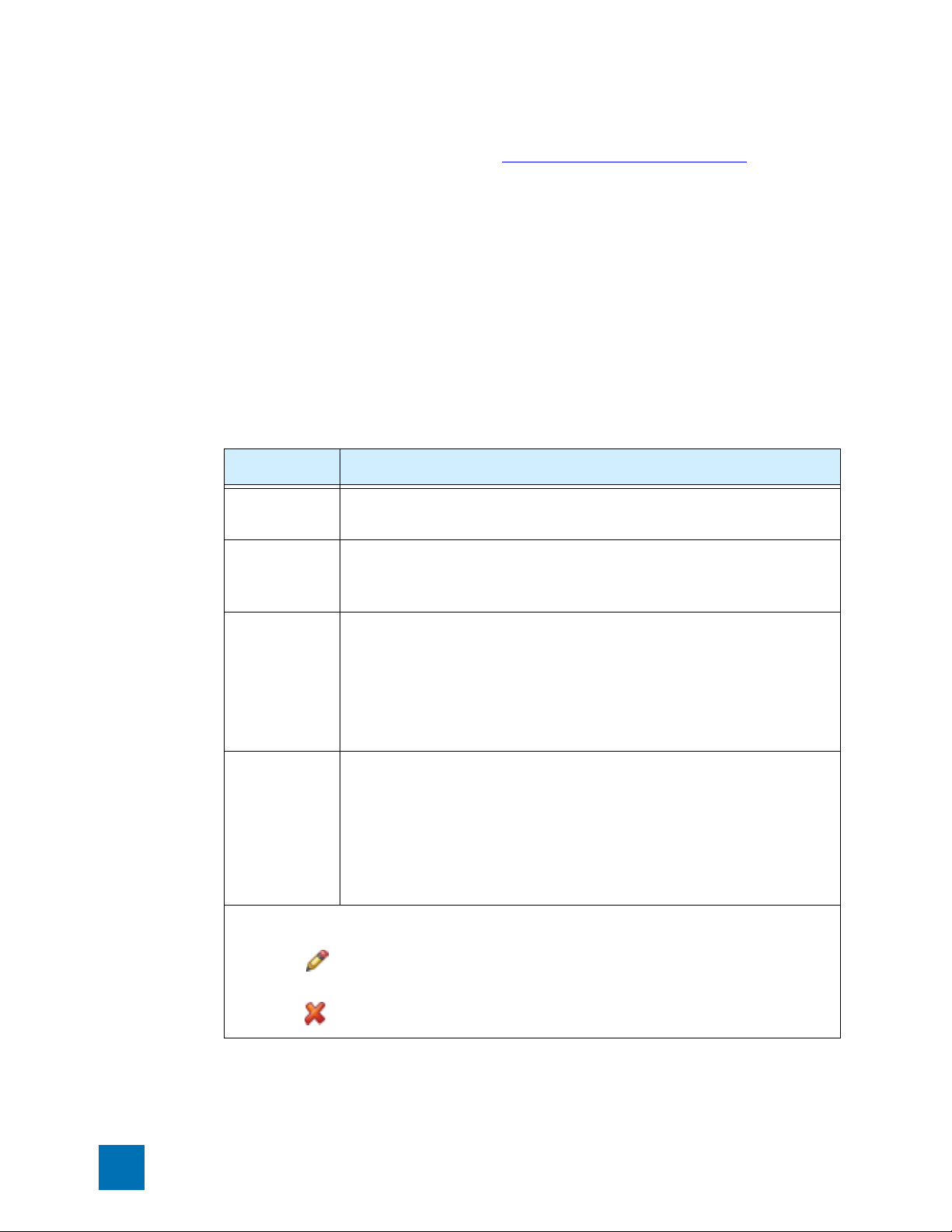
Chapter 4 Firewall
Configuring Virtual Servers
For device maximum configurable values, see “Appendix D‚ “Device Maximum Values”. The following
information applies to Virtual Server configuration:
• Virtual Server traffic is subject to firewall rules. You must set up a firewall rule to allow the traffic for
the desired services through the device firewall. To allow incoming traffic, use the IP address, or the
zone containing the IP address of the LAN device as the destination address of the firewall rule.
• When a Virtual Server is created for all services on the external IP interface of the device, all incoming
sessions, not otherwise intercepted as other private LAN servers for other services, are directed to the
server’s IP address. This configuration will result in loss of management access to the device from the
WA N .
Virtual Servers Configuration Parameters
The following table describes the configuration parameters for Virtual Servers.
Table 4–6: Virtual Servers Configuration Parameters
Column Description
Service The name of the Services or Service Group that are allowed to run on the Virtual
Server.
Local IP The IP address of the server on the LAN to which the Virtual Server is
redirecting traffic. Through one-to-one NAT or PAT, accesses to the public IP
address will be changed to accesses to the Local IP address/Port.
Public IP
Address
PAT
Local Port
Function(s) The functions available for the Virtual Servers:
The IP address for users to access the service or group of services, that is, the
Virtual Server IP address:
•Select Use external IP interface address to use the external IP interface
address for the device
•Select IP address and then type an IP address that is part of the device’s WAN
IP subnet, but different from the one the device is currently using.
Check PAT to enable Port Address Translation. Then, specify a local port number
to map a service to a different local port.
Normally, the Service would use its default port number, but PAT or NAPT
(Network Address Port Translation) performed by the device allows a user to
translate this to a different port number. This would allow, for example, the LAN
server to run multiple instances of a Web server.
• Edit a the configuration for a Virtual Server. (Click the linked Virtual Server
name to edit the schedule).
• Delete a Virtual Server.
84 X Family LSM User’s Guide V 2.5.1
 Loading...