

Page 1

HP
P9000 RAID Manager User Guide
Abstract
This guide provides information on using HP StorageWorks P9000 RAID Manager Software on HP StorgeWorks P9000 disk
arrays. Included is information on: command usage, configuration file examples, and information on High Availability failover
and failback, Fibre Channel addressing, and Standard input (STDIN) file formats.
HP Part Number: T1610-96043
Published: April 2012
Edition: Eighth
Page 2

© Copyright 2010, 2012 Hewlett-Packard Development Company, L.P.
Confidential computer software. Valid license from HP required for possession, use or copying. Consistent with FAR 12.211 and 12.212, Commercial
Computer Software, Computer Software Documentation, and Technical Data for Commercial Items are licensed to the U.S. Government under
vendor's standard commercial license.
The information contained herein is subject to change without notice. The only warranties for HP products and services are set forth in the express
warranty statements accompanying such products and services. Nothing herein should be construed as constituting an additional warranty. HP shall
not be liable for technical or editorial errors or omissions contained herein.
Acknowledgements
Microsoft®, Windows®, Windows® XP, and Windows NT® are U.S. registered trademarks of Microsoft Corporation.
Java and Oracle are registered trademarks of Oracle and/or its affiliates.
UNIX® is a registered trademark of The Open Group.
Export Requirements
You may not export or re-export this document or any copy or adaptation in violation of export laws or regulations.
Without limiting the foregoing, this document may not be exported, re-exported, transferred or downloaded to or within (or to a national resident
of) countries under U.S. economic embargo, including Cuba, Iran, North Korea, Sudan, and Syria. This list is subject to change.
This document may not be exported, re-exported, transferred, or downloaded to persons or entities listed on the U.S. Department of Commerce
Denied Persons List, Entity List of proliferation concern or on any U.S. Treasury Department Designated Nationals exclusion list, or to parties directly
or indirectly involved in the development or production of nuclear, chemical, biological weapons, or in missile technology programs as specified
in the U.S. Export Administration Regulations (15 CFR 744).
Revision History
DescriptionDateEdition
Applies to version 01.24.13 or later.October 2010First
Applies to version 01.24.13 or later.November 2010Second
Applies to version 01.24.16 or later.January 2011Third
Applies to version 01.25.03 or later.May 2011Fourth
Applies to version 01-25-03/06 or later.August 2011Fifth
Applies to version 01-25-03/06 or later.September 2011Sixth
Applies to version 01-26-03 or later.November 2011Seventh
Applies to version 01-27-03/xx or laterApril 2012Eighth
Page 3

Contents
1 Overview..................................................................................................8
About RAID Manager...............................................................................................................8
RAID Manager functions available on the P9500 storage system....................................................8
Provisioning function.............................................................................................................9
Asynchronous command processing.......................................................................................9
Command execution modes................................................................................................10
Precheck function...............................................................................................................10
Command execution by the out-of-band method.....................................................................11
User authentication............................................................................................................12
LDEV nickname function......................................................................................................12
LDEV grouping function......................................................................................................13
Resource group function......................................................................................................13
Resource group locking function...........................................................................................13
RAID Manager functions available on all RAID storage systems....................................................14
In-system replication...........................................................................................................14
Remote replication.............................................................................................................14
Data protection..................................................................................................................14
2 RAID Manager software environment..........................................................15
Overview of the RAID Manager software environment.................................................................15
RAID Manager components on the RAID storage system..............................................................15
Command device...............................................................................................................15
Command device guarding............................................................................................16
Alternate command device function.................................................................................17
Define the remote command device.................................................................................18
RAID Manager and the SCSI command interface...................................................................18
Command competition...................................................................................................19
Command flow.............................................................................................................19
Issuing commands for LDEVs within a LUSE device.............................................................20
RAID Manager instance components on the host server...............................................................20
HORCM operational environment........................................................................................20
RAID Manager instance configurations.................................................................................21
Host machines that can be paired........................................................................................23
Configuration definition file.................................................................................................24
Overview.....................................................................................................................24
Configuration definition file settings.................................................................................26
Configuration definition for cascading volume pairs...............................................................33
Configuration file and mirror descriptors...........................................................................33
Cascading connection and configuration files...................................................................34
Business Copy..............................................................................................................35
Cascading connections for Continuous Access Synchronous and Business Copy....................36
RAID Manager software files....................................................................................................39
RAID Manager files supplied with the software......................................................................39
RAID Manager files for UNIX-based systems.....................................................................39
RAID Manager files for Windows-based systems...............................................................40
RAID Manager files for OpenVMS-based systems..............................................................41
RAID Manager log and trace files.............................................................................................42
RAID Manager log files......................................................................................................42
RAID Manager trace files....................................................................................................44
RAID Manager trace control command.................................................................................44
Command error logging for audit........................................................................................45
User-created files....................................................................................................................46
Contents 3
Page 4

3 RAID Manager functions on P9500............................................................48
Command execution using in-band and out-of-band methods.......................................................48
User authentication.................................................................................................................49
Command operation authority and user authentication................................................................49
Controlling User Role..........................................................................................................49
Controlling user resources...................................................................................................50
The commands that are executed depending on the operation authorities managed by Remote
Web Console and the SVP..................................................................................................51
The relationship between resource groups and command operations.............................................53
Resource lock function.............................................................................................................55
Command execution modes.....................................................................................................56
Overview..........................................................................................................................56
Context check....................................................................................................................57
How to check...............................................................................................................57
Details of check contents................................................................................................58
Configuration check...........................................................................................................63
LDEV group function................................................................................................................63
Overview..........................................................................................................................63
Device group definition methods..........................................................................................65
Read operations and command device settings......................................................................66
Device group function.........................................................................................................66
Device group creation....................................................................................................68
LDEV addition to device group........................................................................................68
LDEV deletion from device group.....................................................................................69
Device group deletion....................................................................................................70
Copy group function...........................................................................................................71
Copy group creation.....................................................................................................73
LDEV addition to a copy group.......................................................................................73
LDEV deletion from copy group.......................................................................................74
Copy group deletion......................................................................................................75
Pair operation by specifying a copy group.......................................................................76
Pair operations with volumes for mainframe................................................................................79
Using dummy LU................................................................................................................79
Displayed pair statuses.......................................................................................................80
Multi-platform volumes........................................................................................................81
Differences in replication commands....................................................................................82
4 Starting up RAID Manager........................................................................84
Starting up on UNIX systems....................................................................................................84
Starting up on Windows systems..............................................................................................85
Starting up on OpenVMS systems.............................................................................................86
Starting RAID Manager as a service (Windows systems)..............................................................87
5 Provisioning operations with RAID Manager................................................89
About provisioning operations..................................................................................................89
Overview of the configuration setting command.....................................................................89
Synchronous command processing..................................................................................89
Asynchronous command processing................................................................................89
Asynchronous commands...............................................................................................90
Help on configuration setting commands...............................................................................91
LDEV nickname function......................................................................................................91
Available provisioning operations.............................................................................................91
Available provisioning operation (specifying device group)..........................................................97
Summary..........................................................................................................................97
Operation method.............................................................................................................98
Common operations when executing provisioning operations.......................................................99
4 Contents
Page 5

Resource group operations.....................................................................................................100
Creating resource groups..................................................................................................100
Deleting resource groups..................................................................................................100
Allocating resources that are allocated to resource groups to the other resource groups.............100
Execution example...........................................................................................................101
Internal volume operations.....................................................................................................101
Creating internal volumes (open volume).............................................................................101
Script examples...............................................................................................................102
Creating internal volumes (mainframe volume)..........................................................................104
Script examples....................................................................................................................105
Virtual volume (Thin Provisioning) operations............................................................................106
Creating virtual volumes (Thin Provisioning).........................................................................106
Script examples...............................................................................................................107
Virtual volume (Thin Provisioning Z) operations.........................................................................109
Creating virtual volumes (Thin Provisioning Z)......................................................................109
Script examples...............................................................................................................109
Virtual volume (Smart Tiers) operations....................................................................................110
Operational flow.............................................................................................................110
Creating virtual volumes (Smart Tiers).................................................................................112
Script examples...............................................................................................................113
External volume operations....................................................................................................116
Creating external volumes.................................................................................................116
Script Examples...............................................................................................................117
6 Data replication operations with RAID Manager.........................................120
About data replication operations...........................................................................................120
Features of paired volumes....................................................................................................120
Using RAID Manager with Business Copy and Continuous Access Synchronous............................121
Business Copy operations......................................................................................................122
Business Copy duplicated mirroring....................................................................................122
Business Copy cascading pairs..........................................................................................123
Restrictions for Business Copy cascading volumes............................................................124
Restriction for Continuous Access Synchronous/Business Copy cascading volumes...............125
Continuous Access Synchronous operations..............................................................................125
Continuous Access Synchronous takeover commands............................................................125
Continuous Access Synchronous remote commands..............................................................126
Continuous Access Synchronous local commands.................................................................127
Continuous Access Synchronous, Business Copy, and Continuous Access Journal operations...........128
Continuous Access Synchronous/Business Copy volumes.......................................................128
Continuous Access Synchronous/Business Copy/Continuous Access Journal volume status.........129
Continuous Access Asynchronous, Continuous Access Synchronous, and Continuous Access Journal
volumes..........................................................................................................................133
Sidefile cache for Continuous Access Asynchronous.........................................................135
Continuous Access Asynchronous transition states and sidefile control................................136
Continuous Access Asynchronous/Continuous Access Journal error state.............................137
Continuous Access Synchronous/Continuous Access Asynchronous and Continuous Access Journal
fence level settings...........................................................................................................138
Setting the fence level..................................................................................................139
Snapshot operations.............................................................................................................139
Snapshot volumes............................................................................................................140
Creating a Snapshot pair..................................................................................................140
Snapshot pair status.........................................................................................................140
Pair status relationship to Snapshot commands.....................................................................141
Controlling Auto LUN............................................................................................................142
Specifications for Auto LUN...............................................................................................142
Contents 5
Page 6

Commands to control Auto LUN.........................................................................................143
Relations between “cc” command issues and status..............................................................146
Restrictions for Auto LUN...................................................................................................147
Continuous Access Journal MxN configuration and control.........................................................147
Overview........................................................................................................................147
Policy ............................................................................................................................148
horcm.conf......................................................................................................................148
Command specifications...................................................................................................149
pairdisplay command..................................................................................................149
pairsplit command......................................................................................................150
Notice on system operation...............................................................................................152
Configuration examples....................................................................................................153
Remote volume discovery.......................................................................................................155
Discovering a remote volume.............................................................................................156
7 Data protection operations with RAID Manager..........................................158
Data protection operations.....................................................................................................158
Data Retention.................................................................................................................158
Restrictions on Data Retention volumes...........................................................................159
Database Validator..........................................................................................................159
Restrictions on Database Validator.................................................................................160
Protection parameters and operations......................................................................................161
Data Protection facility...........................................................................................................161
Data Protection Facility specifications..................................................................................162
Examples for configuration and protected volumes...............................................................162
Target commands for protection.........................................................................................163
permission command.......................................................................................................164
New options for security...................................................................................................164
raidscan –find inst.......................................................................................................164
raidscan –find verify [MU#]..........................................................................................164
raidscan –f[d].............................................................................................................165
pairdisplay –f[d].........................................................................................................165
Permitting protected volumes..............................................................................................165
With a $HORCMPERM file...........................................................................................165
Without a $HORCMPERM file: Commands to run on different operating systems.................166
Environment variables.......................................................................................................167
$HORCMPROMOD....................................................................................................167
$HORCMPERM..........................................................................................................167
Determining the protection mode command device...............................................................167
8 Examples of using RAID Manager commands............................................168
Group version control for mixed storage system configurations....................................................168
LDM volume discovery and flushing for Windows.....................................................................168
Volume discovery function.................................................................................................169
Mountvol attached to Windows systems..............................................................................170
System buffer flushing function...........................................................................................171
Special facilities for Windows systems.....................................................................................173
Signature changing facility for Windows systems.................................................................173
GPT disk for Windows......................................................................................................175
Directory mount facility for Windows systems.......................................................................175
Host group control................................................................................................................177
Specifying a host group....................................................................................................177
Commands and options including a host group...................................................................178
Using RAID Manager SLPR security.........................................................................................178
Specifying the SLPR Protection Facility.................................................................................179
SLPR configuration examples.............................................................................................180
6 Contents
Page 7

9 Troubleshooting......................................................................................184
General troubleshooting........................................................................................................184
Operational notes and restrictions for RAID Manager operations................................................184
Error messages and error codes.............................................................................................187
System log messages........................................................................................................187
Command error messages ................................................................................................188
Generic error codes (horctakeover and pair commands).......................................................194
Generic error codes (raidscan, raidqry, raidar, horcctl).........................................................195
Specific error codes.........................................................................................................196
SSB codes......................................................................................................................197
SSB code returned by a replication command.................................................................198
SSB code returned by the configuration setting command (raidcom command)....................198
10 Support and other resources...................................................................246
Contacting HP......................................................................................................................246
Subscription service..........................................................................................................246
Documentation feedback..................................................................................................246
Related information...............................................................................................................246
HP websites....................................................................................................................247
Conventions for storage capacity values..................................................................................247
Typographic conventions.......................................................................................................247
Glossary..................................................................................................249
Index.......................................................................................................252
Contents 7
Page 8

1 Overview
Unless otherwise specified, the term P9000 in this guide refers to the following disk array:
• P9500 Disk Array
NOTE: The raidcom commands described in this guide are supported only on the P9000 disk
arrays. All other commands are supported on both the P9000 and the XP24000/XP20000,
XP12000/XP10000, SVS200, and XP1024/XP128 disk arrays.
The GUI illustrations in this guide were created using a Windows computer with the Internet Explorer
browser. Actual windows may differ depending on the operating system and browser used. GUI
contents also vary with licensed program products, storage system models, and firmware versions.
RAID Manager (RAID Manager) enables you to perform storage system configuration and data
management operations by issuing commands to the RAID storage systems.
About RAID Manager
RAID Manager enables you to perform storage system configuration and data management
operations by issuing commands to the RAID storage systems. RAID Manager operations can be
used on the following storage systems:
• P9500 Disk Array
• XP24000/XP20000 Disk Array
• XP12000 Disk Array
• XP10000 Disk Array
• XP1024/XP128 Disk Array
RAID Manager continues to provide the proven functionality that has been available for the
XP24000/XP20000 Disk Array storage systems and previous storage system models, including
in-system replication, remote replication, and data protection operations.
In addition, RAID Manager now provides command-line access to the same provisioning and
storage management operations that are available in the Remote Web Console graphical user
interface. RAID Manager commands can be used interactively or in scripts to automate and
standardize storage administration functions, thereby simplifying the job of the storage administrator
and reducing administration costs. This new version of RAID Manager also provides improved
ease of use while at the same time reducing risk of error.
RAID Manager functions available on the P9500 storage system
The following table lists and describes new RAID Manager functions available on the P9500.
DescriptionItem
Supports configuration setting commands in addition to replication commands.Provisioning function
Asynchronous commands
Supports a command processing method, which returns a response when receiving a
command and executes the actual processing later.
Command execution modes
8 Overview
Supports the transaction mode that executes a script file specified by the -zt option
and the line-by-line mode that executs row-by-row input from the command line.
• Context Check. Checks the consistency of the contents in the script file.
• Configuration check. Checks the contents of the script file if it is operated for the
installed resource.
Page 9

DescriptionItem
At the transaction mode, these checks are performed when these are evaluated as
normal before executing script files. Also, the progress of the check and execution are
displayed in the console.
Precheck function
CLI command in out-of-band
User authentication
LDEV grouping function
Resource group function
Resource group locking
Executes the command checking only (processing is not executed even if no problem
found on the checking result). This is available to specify in both line-by-line mode
and transaction mode (see “Command execution modes” (page 10)).
Makes both replication/provisioning CLIs executable with out-of-band method (see
“Command execution by the out-of-band method” (page 11)).
Supports the user authentication function in conjunction with the Remote Web
Console/SVP. Once user authentication is enabled, a command can be executed in
accordance with the authentication controlled by the Remote Web Console/SVP.
User authentication is required in the following cases.
• When executing replication or provisioning operation with out-of-band method.
• When executing provisioning operation with in-band method .
However, user authentication is an option when executing just a replication series
operation with in-band method.
Supports the function to provide a nickname to an LDEV.LDEV nickname function
Puts the multiple LDEVs together so that it can be defined as one device group or one
copy group. By using one defined group, the multiple LDEVs can be operated all
together.
Each user can use resources effectively by grouping resources in the storage system
(LDEV, port, host groups, and pools).
Supports the user locking of the resource (LDEV, ports, and so on) for users between
RAID Manager and SVP or between RAID Manager and another RAID Manager.
Provisioning function
By executing a configuration setting command (raidcom command) from RAID Manager, the
provisioning function such as setting commands or creating LDEVs can be done. For the information
about the configuration setting command (raidcom command), see “Overview of the configuration
setting command” (page 89).
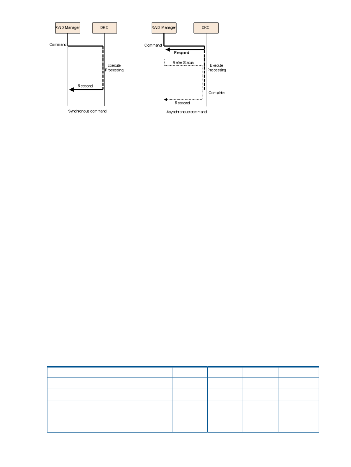
Asynchronous command processing
Within the configuration setting commands (raidcom commands), using asynchronous commands
is a method of command processing applied to a command that takes much time in processing on
the storage system. Once this processing method of command is issued, an additional command
can be executed without having to wait for the command completion that executed just before. It
is also possible to monitor the completion status by using a status reference command.
RAID Manager functions available on the P9500 storage system 9
Page 10
Command execution modes
RAID Manager provides two command execution modes: transaction mode that executes by
specifying a script file with the -zt option, and line-by-line mode that executes a command row-by-row
for the configuration setting commands (raidcom commands).
The transaction mode can execute the following checking.
• Context check: This check is executed when a script file is specified by the -zt option. It checks
the context of preceding commands and determines whether a subsequent command can be
executed.
Specifying example
> raidcom -zt <script_file>
• Configuration check: This check verifies that the actual storage system confirmation is valid
(implemented) for the resources specified in the commands (LDEVs, ports, pools, etc.).
Syntax example:
> raidcom get ldev -ldev_id -cnt 65280 -store<work_file>
> raidcom -zt <script_file> -load<work_file>
Precheck function
RAID Manager provides a precheck function that checks a configuration command before executing
the command for the configuration setting commands (raidcom commands):
In RAID Manager before supporting P9500, an error was returned when the syntax of a command
to be executed was not correct. With this precheck function, the command syntax can be checked
before the command is issued. This function can be specified using either the -checkmode
precheck option or the -zt option.
The following table shows the summary of checking function combinations between precheck
function and the transaction mode.
Table 1 Summary of the checking functions
raidcom -zt <script_file> -load <work_file>
10 Overview
ExecutionConfig checkContext checkSyntax checkCommand syntax
ExecutedNot executedNot executedExecutedraidcom <command>
Not executedNot executedNot executedExecutedraidcom <command> -checkmode precheck
ExecutedNot executedExecutedExecutedraidcom -zt <script file>
ExecutedExecutedExecutedExecutedraidcom get ldev -ldev -cnt 65280 -store<work_file>
Page 11

Table 1 Summary of the checking functions (continued)
raidcom -zt <script_file> -load <work_file> -checkmode
precheck
Command execution by the out-of-band method
In the RAID Manager before supporting P9500, a command can be executed only from the host
connected by the fibre channel directly. This is known as in-band operations. In the RAID Manager
supporting P9500, a command can be executed from any client PC connected to the storage
system via LAN, not just from connected hosts. This is known as out-of-band operations.
• For in-band RAID Manager operations, the command device is used, which is a user-selected
and dedicated logical volume on the storage system that functions as the interface to the
storage system on the UNIX/PC host. The command device accepts read and write commands
that are executed by the storage system.
• For out-of-band RAID Manager operations, a virtual command device is used. The virtual
command device is defined in the configuration definition file by an IP address on the SVP.
RAID Manager commands are issued from the client or the host server and transferred via
LAN to the virtual command device, and the requested operations are then performed by the
storage system.
The following table illustrates in-band and out-of-band RAID Manager operations.
ExecutionConfig checkContext checkSyntax checkCommand syntax
Not executedNot executedExecutedExecutedraidcom -zt <script file> -checkmode precheck
Not executedExecutedExecutedExecutedraidcom get ldev -ldev -cnt 65280 -store<work_file>
RAID Manager functions available on the P9500 storage system 11
Page 12
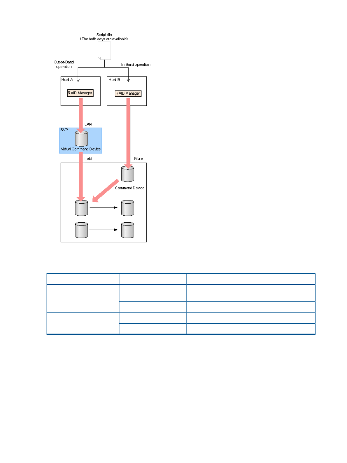
Figure 1 Overview of out-of-band and in-band operations
The following table provides a comparison of in-band and out-of-band operations.
Table 2 Comparison of in-band and out-of-band operations
as if it were a command for the
command device)
directly with the SVP)
User authentication
To enable user authentication, it is required to enable user authentication mode for the command
device of RAID Manager. If the authentication is disabled, provisioning commands and out-of-band
commands cannot be executed.
The user information to be used (user ID or password) are the same with that of Remote Web
Console and SVP.
LDEV nickname function
A unique nickname with up to 32 characters can be given to an LDEV.
SpecificationCommandRoute
ReplicationIn-band (issued from the host
The required or not required of user authentication is
changed by the setting of user authentication.
User authentication is required.Provisioning
User authentication is required.ReplicationOut-of-band (communicating
User authentication is required.Provisioning
12 Overview
Page 13

LDEV grouping function
In the RAID Manager before supporting P9500, it was required to define a copy group for the
configuration definition file on each host. When changing copy group information, editing of the
configuration definition file was required on each host. In the RAID Manager supporting P9500,
the group information can be defined at a time and stored in the storage system. When changing
group information, only one configuration file needs to be edited, saving time and effort and
eliminating the chance for error due to mismatching edits.
This new functionality is implemented using LDEV names, device groups, and copy groups:
• Copy group: A group that is defined by specifying two device groups: one device group from
the primary side and one device group from the secondary side.
• Device group:
A group that is configured with one or more LDEV.◦
◦ A device group can only belong to one copy group.
◦ When creating a mirrored or cascaded pair, each copy group must have unique device
groups and devices names.
• Device name:
A name that can be given to one LDEV per the device group.◦
◦ Each name is associated with a device group in which the LDEV belongs to.
◦ An LDEV nickname can be given to the LDEV as a unique name for the LDEV that is not
related with device group. Only one LDEV nickname can be given for each LDEV.
◦ Device group:
A group that is configured with one or more LDEVs.–
– A device group can belong to only one copy group
– When creating a mirrored of cascaded pair, each copy group must have unique
device groups and device names.
◦ Copy group: A group that is defined by specifying two device groups: one device group
from primary side and one device group from the secondary side.
Resource group function
Using Resource Group function, a storage administrator in each resource group can access
respective resource groups only. The storage administrator in each resource group cannot access
the other resources except the one that the administrator manages. This can prevent the risk of
destroying the data by another storage administrator in the other resource groups or of leaking
out the data.
Resource group locking function
The resource group locking function prevents conflict among multiple users:
User scripts cannot be guaranteed to work correctly when there are multiple users (Remote Web
Console and SVP). You can use the Lock command while the script is running to ensure completion.
To use the Lock command, user authentication is required.
RAID Manager functions available on the P9500 storage system 13
Page 14

RAID Manager functions available on all RAID storage systems
RAID Manager provides the following functionality on all HP RAID storage systems.
• In-system replication
• Remote replication
• Data protection
In-system replication
RAID Manager provides command-line control for in-system replication operations, including
Business Copy and Snapshot. RAID Manager displays Business Copy and Snapshot information
and allows you to perform operations by issuing commands or by executing a script file.
Remote replication
RAID Manager provides command-line control for remote replication operations, including
Continuous Access Synchronous and Continuous Access Journal. RAID Manager displays Continuous
Access Synchronous and Continuous Access Journal information and allows you to perform
operations by issuing commands or by executing a script file.
For remote copy operations, RAID Manager interfaces with the system software and high-availability
(HA) software on the host as well as the software on the RAID storage system. RAID Manager
provides failover operation commands that support mutual hot standby in conjunction with
industry-standard failover products (e.g., MC/ServiceGuard, HACMP, FirstWatch®). RAID Manager
also supports a scripting function for defining multiple operations in a script (or text) file. Using
RAID Manager scripting, you can set up and execute a large number of commands in a short
period of time while integrating host-based high-availability control over copy operations.
Data protection
RAID Manager continues to support data protection operations, including Database Validator and
Data Retention.
• Database Validator. The RAID Manager software provides commands to set and verify
parameters for volume-level validation checking of Oracle database operations. Once validation
checking is enabled, all write operations to the specified volumes must have valid Oracle
checksums. RAID Manager reports a validation check error to the syslog file each time an
error is detected. Database Validator requires the operation of RAID Manager software product
but cannot be controlled via the Remote Web Console software.
• Data Retention. The RAID Manager software enables you to set and verify the parameters for
guarding at the volume level. Once guarding is enabled, the RAID storage system conceals
the target volumes from SCSI commands such as SCSI Inquiry and SCSI Read Capacity,
prevents reading and writing to the volume, and protects the volume from being used as a
copy volume (the Continuous Access Synchronous or Business Copy paircreate operation
fails).
14 Overview
Page 15

2 RAID Manager software environment
The RAID Manager software environment involves components on the RAID storage system(s) and
RAID Manager instance components on the host server(s).
Overview of the RAID Manager software environment
The RAID Manager software environment involves components on the RAID storage systems and
RAID Manager instance components on the host server(s). The RAID Manager components on the
storage systems include the command devices and the data volumes. Each RAID Manager instance
on a host server includes:
• RAID Manager application files, referred to as HORC Manager (HORCM):
Log and trace files◦
◦ A command server
◦ Error monitoring and event reporting files
◦ A configuration management feature
• Configuration definition file (user-defined)
• User execution environments for the HP features, including the commands, a command log,
and a monitoring function.
The RAID Manager commands also have interface considerations (see “RAID Manager and the
SCSI command interface” (page 18)).
RAID Manager components on the RAID storage system
Command device
RAID Manager commands are issued by the RAID Manager software to the RAID storage system
command device. The command device is a user-selected, dedicated logical volume on the storage
system that functions as the interface to the RAID Manager software on the host. The command
device is dedicated to RAID Manager communications and cannot be used by any other
applications. The command device accepts RAID Manager read and write commands that are
issued by the storage system. The command device also returns read requests to the host. The
volume designated as the command device is used only by the storage system and is blocked from
the user. The command device uses 16 MB, and the remaining volume space is reserved for RAID
Manager and its utilities. The command device can be any OPEN-x device (e.g., OPEN-V) that is
accessible to the host. A LUN Expansion volume cannot be used as a command device. A Virtual
LVI/Virtual LUN volume as small as 36 MB (e.g., OPEN-3-CVS) can be used as a command device.
CAUTION: Make sure the volume to be selected as the command device does not contain any
user data. The command device will be inaccessible to the host.
The RAID Manager software on the host issues read and write commands to the command device.
When RAID Manager receives an error notification in reply to a read or write request to the RAID
storage system, the RAID Manager software switchs to an alternate command device, if one is
defined. If a command device is blocked (e.g., for online maintenance), you can switch to an
alternate command device manually. If no alternate command device is defined or available, all
Continuous Access Synchronous and Business Copy commands terminate abnormally, and the
host will not be able to issue commands to the storage system. Therefore, one or more alternate
command devices (see “Alternate command device function” (page 17)) must be set to avoid data
loss and storage system downtime.
Overview of the RAID Manager software environment 15
Page 16

Each command device must be set using the LUN Manager software on Remote Web Console. In
addition, for using a Provisioning command, user authentication is required. Set the security attribute
of the command device with user authentication. For information and instructions on setting a
command device, see the HP P9000 Provisioning for Open Systems User Guide.
Each command device must also be defined in the HORCM_CMD section of the configuration file
for the RAID Manager instance on the attached host. If an alternate command device is not defined
in the configuration file, the RAID Manager software may not be able to use the device.
The RAID Manager Data Protection Facility uses an enhanced command device that has an attribute
to indicate protection ON or OFF.
NOTE:
• For Solaris operations, the command device must be labeled.
• To enable dual pathing of the command device under Solaris systems, make sure to include
all paths to the command device on a single line in the HORCM_CMD section of the
configuration file. Example 1 “Example of alternate path for command device for solaris
systems” shows an example with two controller paths (c1 and c2) to the command device.
Putting the path information on separate lines may cause parsing issues, and failover may not
occur unless the HORCM startup script is restarted on the Solaris system.
Example 1 Example of alternate path for command device for solaris systems
HORCM_CMD
#dev_name dev_name dev_name
/dev/rdsk/c1t66d36s2 /dev/rdsk/c2t66d36s2
Command device guarding
In the customer environment, a command device may be attacked by the maintenance program
of the Solaris Server. After that usable instance is exhausted, the RAID Manager instance would
not start up on all servers (except attacked server). This may happen due to incorrect operation of
the maintenance personnel for the UNIX Server. In this case, the command device should be
protected against operator error, as long as it can be seen as the device file from the maintenance
personnel.
Thus, the RAID microcode (for the command device) and RAID Manager support this protection in
order to guard from similar access.
Guarding method
Currently, assignment of the instance via the command device is ONE phase. Therefore, if the
command device reads a special allocation area of the instance through the maintenance tool and
so on, then it causes a fault of full space of the instance, because the command device interprets
as assignment of the instance from RAID Manager.
RAID Manager has TWO phases that it reads to acquire usable LBA, and writes with the acquired
LBA in attaching sequence to the command device, so the command device will be able to confirm
whether it was required as the assignment for RAID Manager or not, by detecting and adding two
status bits to the instance assignment table.
16 RAID Manager software environment
Page 17
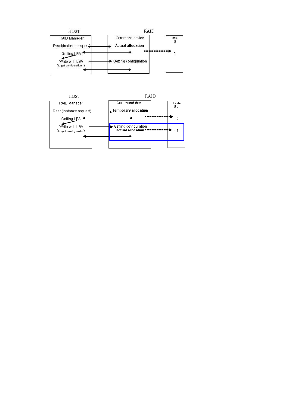
Figure 2 Current assignment sequence
Figure 3 Improved assignment sequence
The command device performs the assignment of an instance through TWO phase that has
“temporary allocation (1 0)” and “actual allocation (1 1)” to the instance assignment table.
If the command device is attacked, the instance assignment table will be filled with “temporary
allocation (1 0)” status, after that the command device will detect a fault of full space as the instance
assignment, and then will clear up all “temporary allocation (1 0)”, and re-assigns the required
instance automatically.
This does not require service personnel to do “OFF/ON” of the command device for clear up the
instance table.
Verifying the RAID Manager instance number
RAID Manager provides a way to verify the number of “temporary allocations (1 0)” and “actual
allocations (1 1)” on the instance table so that you can confirm validity of the RAID Manager
instance number in use. The horcctl -DI command shows the number of RAID Manager
instances since HORCM was started as follows.
Example without command device security:
# horcctl -DICurrent control device = /dev/rdsk/c0t0d0 AI = 14 TI = 0 CI = 1
Example with command device security:
# horcctl -DI
Current control device = /dev/rdsk/c0t0d0*AI = 14 TI = 0 CI = 1
AI : NUM of Actual instances in use
TI : NUM of temporary instances in RAID
CI : NUM of instances using current (own) instance
Alternate command device function
The RAID Manager software issues commands to the command device via the UNIX/PC raw I/O
interface. If the command device fails in any way, all RAID Manager commands are terminated
abnormally, and you cannot use any commands. Because the use of alternate I/O pathing is
platform dependent, restrictions are placed upon it. For example, on HP-UX systems, only devices
RAID Manager components on the RAID storage system 17
Page 18
subject to the LVM can use the alternate path PV-LINK. To avoid command device failure, RAID
Manager supports an alternate command device function.
• Definition of alternate command devices. To use an alternate command device, you must
define two or more command devices for the HORCM_CMD item in the configuration definition
file. When two or more devices are defined, they are recognized as alternate command
devices.
• Timing of alternate command devices. When the HORCM receives an error notification in
reply from the operating system via the raw I/O interface, the alternate command device is
used. It is possible to force a switch to use the alternate the command device by issuing the
horcctl -C switch command provided by RAID Manager.
• Operation of alternating command. If the command device is blocked due to online
maintenance, the switch command should be issued in advance. If the switch command is
issued again after completion of the online maintenance, the previous command device is
activated.
• Multiple command devices on HORCM startup. If at least one command device is available
during one or more command devices described to the configuration definition file, then
HORCM can start with a warning message to the startup log by using the available command
device. Confirm that all command devices can be changed by using the horcctl -C
command option, or HORCM has been started without the warning message to the HORCM
startup log.
Figure 4 Alternate command device function
Define the remote command device
The command device of external storage system that is mapped as a command device of the local
storage system is called as remote command device. By issuing a command to the remote command
device, the operation at the external storage system is realized.
The remote command device is defined by the Remote Web Console. For more information, see
HP StorageWorks P9000 External Storage for Open and Mainframe Systems User Guide.
RAID Manager and the SCSI command interface
When RAID Manager commands are converted into a special SCSI command format, a SCSI
through driver that can send specially formatted SCSI commands to the RAID storage system is
needed. As a result, OS support for RAID Manager depends on the OS capabilities. It is necessary
to use a read/write command that can easily be issued by many UNIX/PC server platforms. For
example, ioctl() can be used for the following platforms: HP-UX, Linux, Solaris, Windows, IRIX64,
OpenVMS and zLinux.
SCSI command format used. Use a RD/WR command that can be used with special LDEVs, since
they should be discriminated from the normal RD/WR command.
Recognition of the control command area (LBA#). The host issues control commands through the
raw I/O special file of a special LDEV. Since the specific LU (command device) receiving these
18 RAID Manager software environment
Page 19

commands is viewed as a normal disk by the SCSI interface, the OS can access its local control
area. The RAID storage system must distinguish such accesses from the control command accesses.
Normally, several megabytes of the OS control area are used starting at the initial LBA#. To avoid
using this area, a specific LBA# area is decided and control commands are issued within this area.
The command LBA# recognized by the storage system is shown below, provided the maximum
OS control area is 16 MB.
Figure 5 Relationship of the special file to the special LDEV
Acceptance of commands. A command is issued in the LBA area of the special LDEV explained
above. The RD/WR command meeting this requirement should be received especially as a RAID
Manager command. A command is issued in the form of WR or WR-RD. When a command is
issued in the form of RD, it is regarded as an inquiry (equivalent to a SCSI inquiry), and a RAID
Manager recognition character string is returned.
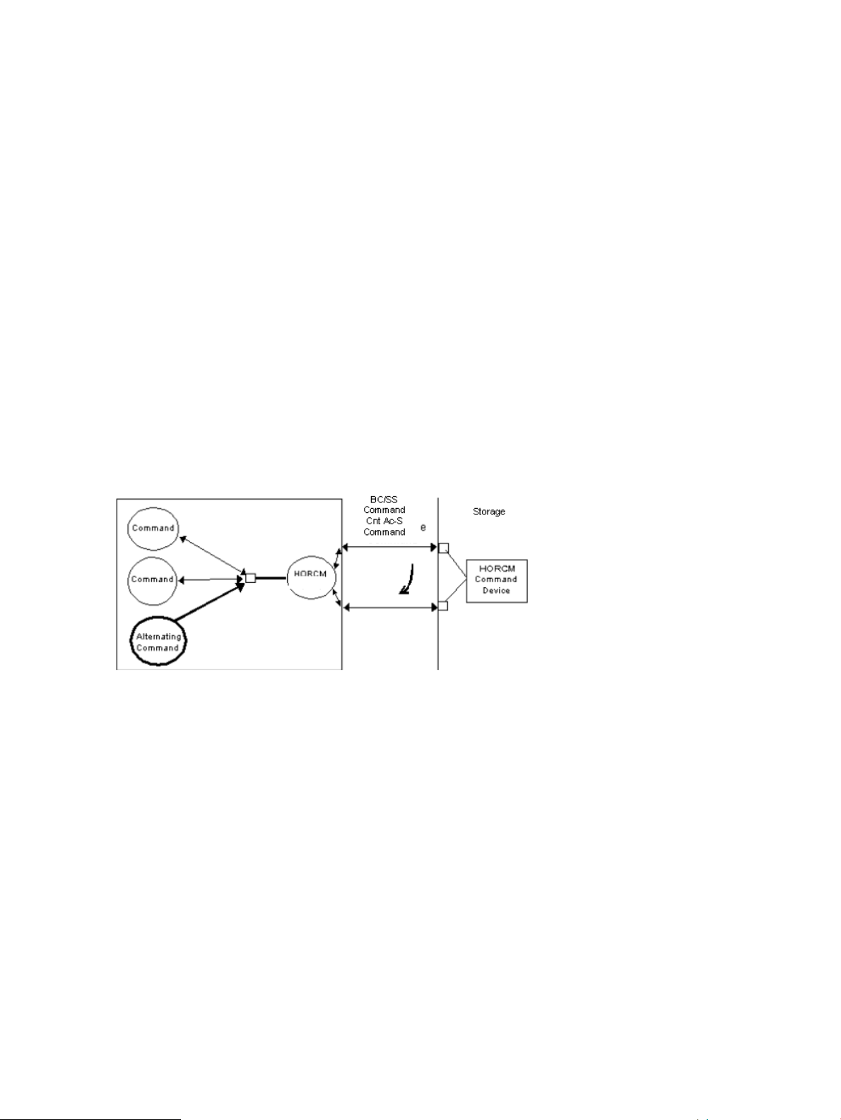
Command competition
The RAID Manager commands are asynchronous commands issued via the SCSI interface. As a
result, if several processes issue these commands to a single LDEV, the storage system cannot take
the proper action. To avoid such a problem, two or more write commands should not be issued
to a single LDEV. The command initiators should not issue two or more write commands to a single
LDEV unless the storage system can receive commands with independent initiator number * LDEV
number simultaneously.
Figure 6 HORCM and command issue process
Command flow
This figure shows the flow of read/write command control for a specified LBA#.
RAID Manager components on the RAID storage system 19
Page 20
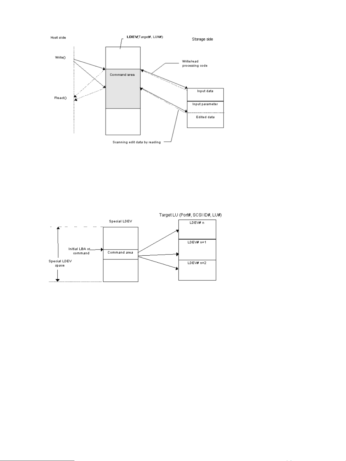
Figure 7 Command flow
Issuing commands for LDEVs within a LUSE device
A LUSE device is a group of LDEVs regarded as a single logical unit. Because it is necessary to
know the configuration of the LDEVs when issuing a command, a new command is used to specify
a target LU and acquire LDEV configuration data (see figure).
Figure 8 LUSE device and command issue
RAID Manager instance components on the host server
HORCM operational environment
The HORCM operates as a daemon process on the host server and is activated either automatically
when the server machine starts up or manually by the startup script. HORCM reads the definitions
specified in the configuration file upon startup. The environment variable HORCM_CONF is used
to define the location of the configuration file to be referenced.
20 RAID Manager software environment
Page 21
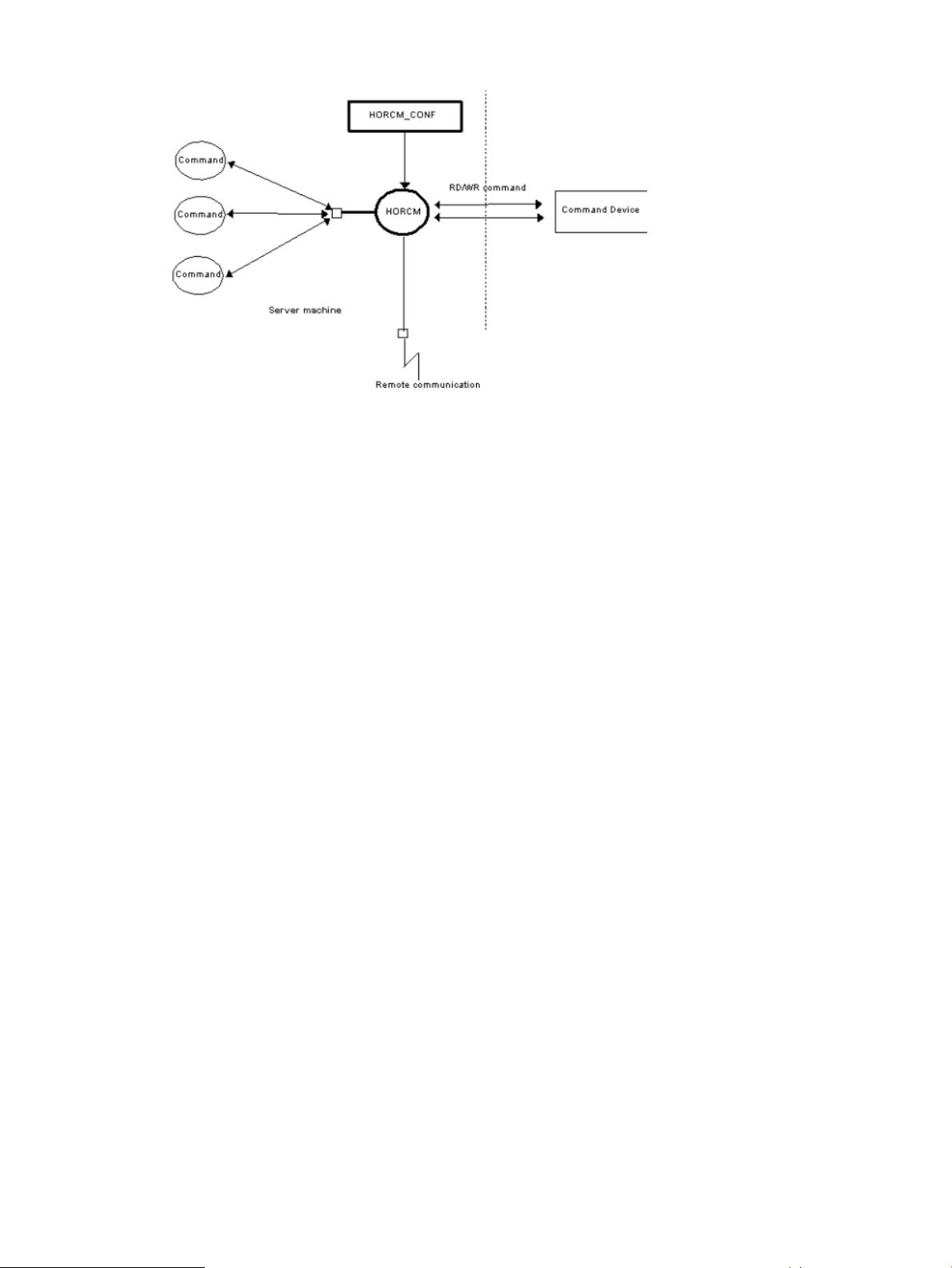
Figure 9 HORCM operational environment
RAID Manager instance configurations
The basic unit of the RAID Manager software structure is the RAID Manager instance. Each copy
of RAID Manager on a server is a RAID Manager instance. Each instance uses its own configuration
definition file to manage volume relationships while maintaining awareness of the other RAID
Manager instances. Each RAID Manager instance normally resides on separate servers (one node
per instance). If two or more instances are run on a single server (e.g., for test operations), it is
possible to activate two or more instances using instance numbers. The RAID Manager commands
to be used are selected by the environment variable (HORCC_MRCF). The default command
execution environment for RAID Manager is Continuous Access Synchronous.
The RAID Manager instance shown in the following figure has a remote execution link and a
connection to the RAID storage system. The remote execution link is a network connection to another
PC to allow you to execute RAID Manager functions remotely. The connection between the RAID
Manager instance and the storage system illustrates the connection between the RAID Manager
software on the host and the command device. The command device accepts RAID Manager
commands and communicates read and write I/Os between the host and the volumes on the
storage system. The host does not communicate RAID Manager commands directly to the volumes
on the storage system -- the RAID Manager commands always go through the command device.
RAID Manager instance components on the host server 21
Page 22

Figure 10 RAID Manager instance configuration & components
The four possible RAID Manager instance configurations are:
• One host connected to one storage system. Connecting one host to one storage system allows
you to maintain multiple copies of your data for testing purposes or as an offline backup. Each
RAID Manager instance has its own operation manager, server software, and scripts and
commands, and each RAID Manager instance communicates independently with the command
device. The RAID storage system contains the command device that communicates with the
RAID Manager instances as well as the primary and secondary volumes of both RAID Manager
instances.
• One host connected to two storage systems. Connecting the host to two storage systems enables
you to migrate data or implement disaster recovery by maintaining duplicate sets of data in
two different storage systems. You can implement disaster recovery solutions by placing the
storage systems in different geographic areas. Each RAID Manager instance has its own
operation manager, server software, and scripts and commands, and each RAID Manager
instance communicates independently with the command device. Each RAID storage system
has a command device that communicates with each RAID Manager instance independently.
Each storage system contains the primary volumes of its connected RAID Manager instance
and the secondary volumes of the other RAID Manager instance (located on the same host in
this case).
• Two hosts connected to one storage system. Having two attached hosts to one storage system,
one host for the primary volume and the other host for the secondary volume, allows you to
maintain and administer the primary volumes while the secondary volumes can be taken offline
for testing. The RAID Manager instances of separate hosts are connected via the LAN so that
they can maintain awareness of each other. The RAID storage system contains the command
device that communicates with both RAID Manager instances (one on each host) and the
primary and secondary volumes of both RAID Manager instances
• Two hosts connected to two storage systems. Two hosts connected to two storage systems also
allows the most flexible disaster recovery plan, because both sets of data are administered
22 RAID Manager software environment
Page 23
by different hosts. This guards against storage system failure as well as host failure. The RAID
Manager instances of separate hosts are connected via the LAN so that they can maintain
awareness of each other. Each RAID storage system has a command device that communicates
with each RAID Manager instance independently. Each storage system contains the primary
volumes of its connected RAID Manager instance and the secondary volumes of the other RAID
Manager instance (located on a different host in this case).
Host machines that can be paired
When you perform a pair operation, the version of RAID Manager should be the same on the
primary and secondary sites. As a particular application uses HORC, users sometimes use a HORC
volume as the data backup volume for the server. In this case, RAID Manager requires that the
RAID Manager instance correspond to each OS platform that is located on the secondary site for
the pair operation of data backup on the primary servers of each OS platform.
However, it is possible to prepare only one server at a secondary site by supporting RAID Manager
communications among different OSs (including the converter for little-endian vs big-endian).
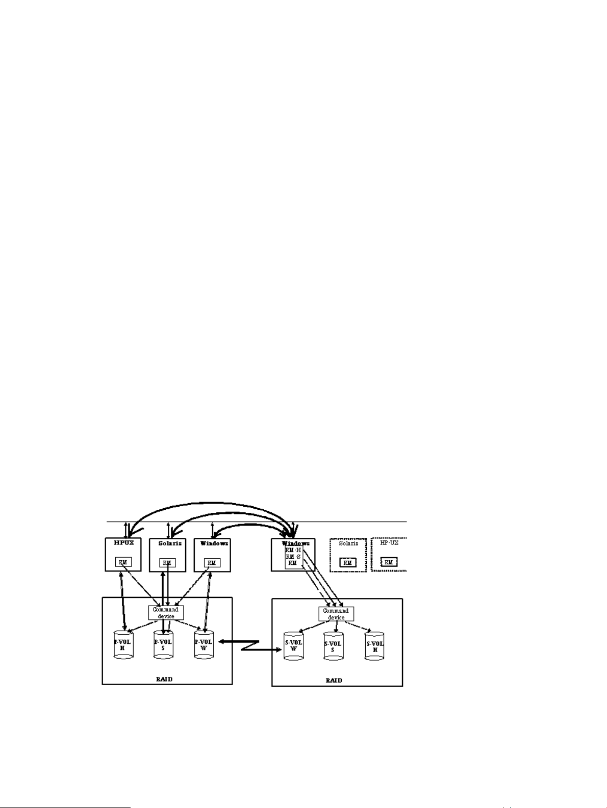
However, it is possible to prepare only one server at a secondary site by supporting RAID Manager
communications among different OSs (including the converter for little-endian vs big-endian).
Figure 11 (page 23) represents RAID Manager’s communication among different OSs, and
Table 3 (page 24) shows the supported communication (32-bit, 64-bit, MPE/iX) among different
OSs. Please note the following terms that are used in the example:
• RM-H: Value of HORCMFCTBL environment variable for an HP-UX RAID Manager instance
on Windows
• RM-S: Value of HORCMFCTBL environment variable for a Solaris RAID Manager instance on
Windows
Restriction: RAID Manager for MPE/iX cannot communicate with 64-bit HORCM.
Restriction: RAID Manager’s communications among different operating systems is supported on
HP-UX, Solaris, AIX, Linux, and Windows (this is not supported on Tru64 UNIX/Digital UNIX).
Also, RAID Manager does not require that the HORCMFCTBL environment variable be set—except
for RM-H and RM-S instances (to ensure that the behavior of the operating system platform is
consistent across different operating systems).
Figure 11 RAID Manager communication among different operating systems
RAID Manager instance components on the host server 23
Page 24

Table 3 Supported RAID Manager (HORCM) communication
Configuration definition file
Overview
The RAID Manager configuration definition file is a text file that defines a RAID Manager instance.
The connected hosts, volumes and groups known to the RAID Manager instance are defined in the
configuration definition file. Physical volumes (special files) used independently by the servers are
combined when paired logical volume names and group names are given to them. The configuration
definition file describes the correspondence between the physical volumes used by the servers and
the paired logical volumes and the names of the remote servers connected to the volumes. See the
HP StorageWorks P9000 RAID Manager Installation and Configuration User Guide for instructions
on creating the RAID Manager configuration definition file.
Figure 12 (page 24) illustrates the configuration definition of paired volumes.
Example 2 “Configuration file example — UNIX-based servers” shows a sample configuration file
for a UNIX-based operating system. Figure 13 (page 25) shows a sample configuration file for a
Windows operating system.
MPE/iXHORCM 64 bitHORCM 32 bitHORCM
bigbiglittlebiglittle
AV-AVAVAVlittle32 bit
AV-AVAVAVbig
NA-AVAVAVlittle64 bit
-----big
AV-NAAVAVbigMPE/iX
Figure 12 Configuration definition of paired volumes
24 RAID Manager software environment
Page 25

# at the head of each line is used to insert a comment in the configuration file.
Example 2 Configuration file example — UNIX-based servers
HORCM_MON
#ip_addressservicepoll(10ms)timeout(10ms)
HST1horcm10003000
HORCM_CMD
#unitID 0... (seq#30014)
#dev_name dev_name dev_name
dev/rdsk/c0t0d0
#unitID 1... (seq#30015)
#dev_name dev_name dev_name
/dev/rdsk/c1t0d0
HORCM_DEV
#dev_groupdev_nameport#TargetIDLU#MU#
oradboradb1CL1-A3 10
oradboradb2CL1-A3 11
oralogoralog1CL1-A5 0
oralogoralog2CL1-A15 0
oralogoralog3CL1-A15 1
oralogoralog4CL1-A15 1 h1
HORCM_INST
#dev_groupip_addressservice
oradbHST2horcm
oradbHST3horcm
oralogHST3horcm
Figure 13 Configuration file example — Windows servers
The following table lists the parameters defined in the configuration file and specifies the default
value, type, and limit for each parameter.
Table 4 Configuration (HORCM_CONF) parameters
RAID Manager instance components on the host server 25
LimitTypeDefaultParameter
64 charactersCharacter stringNoneip_address
15 charactersCharacter string or numeric valueNoneService
NoneNumeric value*1000poll (10 ms)
Page 26

Table 4 Configuration (HORCM_CONF) parameters (continued)
HORCM_DEV
HORCM_CMD
LimitTypeDefaultParameter
NoneNumeric value*3000timeout (10 ms)
31 charactersCharacter stringNonedev_name for
31 charactersCharacter stringNonedev_group
Recommended value = 8 char.
or less
31 charactersCharacter stringNoneport #
7 charactersNumeric value*Nonetarget ID
7 charactersNumeric value*NoneLU#
7 charactersNumeric value*0MU#
12 charactersNumeric valueNoneSerial#
6 charactersNumeric valueNoneCU:LDEV(LDEV#)
63 charactersCharacter stringNonedev_name for
Recommended value = 8 char.
or less
*Use decimal notation for numeric values (not hexadecimal).
Do not edit the configuration definition file while RAID Manager is running. Shut down RAID
Manager, edit the configuration file as needed, and then restart RAID Manager.
Do not mix pairs created with the "At-Time Split" option (-m grp) and pairs created without this
option in the same group defined in the RAID Manager configuration file. If you do, a pairsplit
operation might end abnormally, or S-VOLs of the P-VOLs in the same consistency group (CTG)
might not be created correctly at the time the pairsplit request is received.
Configuration definition file settings
(1) HORCM_MON
The monitor parameter (HORCM_MON) defines the following values:
• Ip_address: The IP address of the local host. When HORCM has two or more network addresses
on different subnets for communication, this must be set to NONE.
• Service: Specifies the UDP port name assigned to the HORCM communication path, which is
registered in "/etc/services" ("\WINNT\system32\drivers\etc\services" in Windows,
"SYS$SYSROOT:[000000.TCPIP$ETC]SERVICES.DAT" in OpenVMS). If a port number is
specified instead of a port name, the port number will be used.
• Poll: The interval for monitoring paired volumes. To reduce the HORCM daemon load, make
this interval longer. If set to -1, the paired volumes are not monitored. The value of -1 is specified
when two or more RAID Manager instances run on a single machine.
• Timeout: The time-out period of communication with the remote server.
(2) HORCM_CMD
When using the in-band method, this command parameter (HORCM_CMD) defines the UNIX
device path or Windows physical device number and specifies a command device that can access
the RAID Manager.
The detailed are described in the following.
In-band method
26 RAID Manager software environment
Page 27

The command device must be mapped to the SCSI/fibre using LUN Manager. You can define
more than one command device to provide failover in case the original command device becomes
unavailable (see “Alternate command device function” (page 17)). The mapped command devices
can be identified by the “-CM” of product ID field of the inqraid command.
# ls /dev/rdsk/c1t0* | /HORCM/usr/bin/inqraid -CLI -sortDEVICE_FILE PORT SERIAL LDEV CTG H/M/12 SSID R:Group
PRODUCT_ID
c1t0d0s2 CL2-E 63502 576 - - - - OPEN-V-CM
c1t0d1s2 CL2-E 63502 577 - s/s/ss 0006 1:02-01 OPEN-V -SUN
c1t0d2s2 CL2-E 63502 578 - s/s/ss 0006 1:02-01 OPEN-V -SUN
The command device of UNIX host (Solaris) on the above example is described in the following.
/dev/rdsk/c1t1d0s2
The command device of Windows host is described in the following.
\\.\PhysicalDrive2 or \\.\CMD-63502
After the process of command device mapping, set HORCM_CMD of the configuration definition
file as follows.
• \\.\CMD-<Serial Number>:<Device special file name>
<Serial Number>: Sets the serial number.
<Device special file name>: Sets the device special file name of a command device.
Example
When the serial number, 64015 and device special file name, /dev/rdsk/*is specified:
HORCM_CMD
#dev_name dev_name dev_name
\\.\CMD-64015:/dev/rdsk/*
Out-of-band method
When executing commands using the out-of-band method, create a virtual command device. To
create a virtual command device, specify as the following to the configuration definition file.
• \\.\IPCMD-<SVP IP address>-<UDP communication port number>[-Unit ID]
<SVP IP address>: Sets an IP address of SVP.
<UDP communication port number>: Sets the UDP communication port number. This value is
fixed (31001).
[-Unit ID]: Sets the unit ID of the storage system for the multiple units connection configuration.
This can be omitted.
The following expresses the case of IPv4.
HORCM_CMD#dev_name dev_name dev_name\\.\IPCMD-158.214.135.113-31001
The following expresses the case of IPv6.
HORCM_CMD#dev_name dev_name dev_name\\.\IPCMD-fe80::209:6bff:febe:3c17-31001
NOTE: To enable dual pathing of the command device under Solaris systems, make sure to
include all paths to the command device on a single line in the HORCM_CMD section of the config
file. Putting the path information on separate lines may cause parsing issues, and failover may not
occur unless the HORCM startup script is restarted on the Solaris system.
When a server is connected to two or more storage systems, the HORCM identifies each storage
system using the unit ID (see Figure 14 (page 28)). The unit ID is assigned sequentially in the order
described in this section of the configuration definition file. When the storage system is shared by
two or more servers, each server must be able to verify that the unit ID is the same Serial# (Seq#)
among servers. This can be verified using the raidqry command.
RAID Manager instance components on the host server 27
Page 28

Figure 14 Configuration and Unit IDs for Multiple Storage systems
dev_name for Windows
In Windows SAN environment, “Volume{guid}” will be changed on every re-boot under
MSCS/Windows2k3, if Windows finds the same signature on the command device connected
with Multi-Path.Therefore, find NEW “Volume{guid}”, and change “Volume{guid}” described in
the RAID Manager configuration file. Thus, RAID Manager supports the following naming format
specifying Serial#/LDEV#/Port# as notation of the command device for only Windows.
\\.\CMD-Ser#-ldev#-Port#
HORCM_CMD
#dev_name dev_name dev_name
\\.\CMD-30095-250-CL1-A
To allow more flexibility, RAID Manager allows the following format.
• For minimum specification
Specifies to use any command device for Serial#30095 \\.\CMD-30095 If Windows has
two different array models that share the same serial number, fully define the serial number,
ldev#, port and host group for the CMDDEV.
• For under Multi Path Driver
Specifies to use any port as the command device for Serial#30095, LDEV#250
\\.\CMD-30095-250
• For full specification
Specifies the command device for Serial#30095, LDEV#250 connected to Port CL1-A, Host
group#1 \\.\CMD-30095-250-CL1-A-1
• Other example
\\.\CMD-30095-250-CL1-A
\\.\CMD-30095-250-CL1
dev_name for UNIX
In the UNIX SAN environment, a device file name is changed at the failover operation under the
UNIX SAN environment, or each reboot process under the Linux when the SAM is reconfigured.
RAID Manager user is required to change the HORCM_CMD described in the RAID Manager
configuration file by searching new “Device special file”. Therefore, RAID Manager supports the
following naming format to specify “Serial#/LDEV#/Port#:HINT” as an expression way of command
device for UNIX.
\\.\CMD-Ser#-ldev#-Port#:HINT
28 RAID Manager software environment
Page 29

HORCM_CMD
#dev_name dev_name dev_name
\\.\CMD-30095-250-CL1-A-1:/dev/rdsk/
once this name is specified, HORCM finds the “\CMD-Serial#-Ldev#-Port#” from the device file
specified by the HINT at the time of HORCM startup. HINT must specifies to be end with “/” for
the directory of the device file name or the directory that includes the pattern of device filename,
as shown in the following.
Finds CMD, which is specified by /dev/rdsk/:/dev/rdsk/*
Finds CMD, which is specified by /dev/rdsk/c10:/dev/rdsk/c10*
Finds CMD, which is specified by /dev/rhdisk:/dev/rhdisk*
A device file is displayed while HINT is filtered with the following pattern.
HP-UX: /dev/rdsk/* or /dev/rdisk/disk*
Solaris: /dev/rdsk/*s2, AIX: /dev/rhdisk*
Linux: /dev/sd...., zLinux : /dev/sd....
MPE/iX: /dev/...
Tru64: /dev/rrz*c or /dev/rdisk/dsk*c or /dev/cport/scp*
DYNIX: /dev/rdsk/sd*
IRIX64: /dev/rdsk/*vol or /dev/rdsk/node_wwn/*vol/*
If HINT is already specified, “:HINT” can be omitted with the following command devices, and
the command devices are retrieved from the already stored Inquiry information, which is not
required to execute device scanning.
HORCM_CMD
#dev_name dev_name dev_name
\\.\CMD-30095-250-CL1:/dev/rdsk/ \\.\CMD-30095-250-CL2
• Basic Specification
Specifies when an optional command device of Serial#30095 is used.
\\.\CMD-30095:/dev/rdsk/
• Driver in the multi-path environment
Specifies when an optional port is used as a command device for Serial#30095, LDEV#250.
\\.\CMD-30095-250:/dev/rdsk/
• For full specification
Specifies a command device for Serial#30095, LDEV#250:, which is connected to Port CL1-A,
Host group#1.
• Other example
\\.\CMD-30095-250-CL1:/dev/rdsk/ \\.\CMD-30095-250-CL2
\\.\CMD-30095:/dev/rdsk/c1 \\.\CMD-30095:/dev/rdsk/c2
(3) HORCM_DEV
The device parameter (HORCM_DEV) defines the RAID storage system device addresses for the
paired logical volume names. When the server is connected to two or more storage systems, the
unit ID is expressed by port# extension. Each group name is a unique name discriminated by a
server that uses the volumes, the attributes of the volumes (such as database data, redo log file,
UNIX file), recovery level, etc. The group and paired logical volume names described in this item
must reside in the remote server. The hardware SCSI/fibre bus, target ID, and LUN as hardware
components need not be the same.
RAID Manager instance components on the host server 29
Page 30

The following values are defined in the HORCM_DEV parameter:
• dev_group: Names a group of paired logical volumes. A command is executed for all
corresponding volumes according to this group name.
• dev_name: Names the paired logical volume within a group (i.e., name of the special file or
unique logical volume). The name of paired logical volume must be different to the dev name
in another group.
• Port#: Defines the RAID storage system port number of the volume that corresponds to the
dev_name volume. The following “n” shows unit ID when the server is connected to two or
more storage systems (e.g., CL1-A1 = CL1-A in unit ID 1). If the “n” option is omitted, the unit
ID is 0. The port is not case sensitive (e.g., CL1-A= cl1-a= CL1-a= cl1-A).
OptionOptionOptionBasic-
RnQnPnNnMnLnKnJnHnGnFnEnDnCnBnAnCL1
RnQnPnNnMnLnKnJnHnGnFnEnDnCnBnAnCL2
The following ports can be specified only for the XP1024/XP128 Disk Array:
OptionOptionOptionBasic-
rnqnpnnnmnlnknjnhngnfnendncnbnanCL3
rnqnpnnnmnlnknjnhngnfnendncnbnanCL4
For XP1024/XP128 Disk Array, RAID Manager supports four types of port names for host groups:
• Specifying the port name without a host group: CL1-A CL1-An where n is the unit ID if
there are multiple RAID storage systems
• Specifying the Port name without a host group CL1-A-g where g is the host group CL1-An-g
where n-g is the host group g on CL1-A in unit ID=n
The following ports can be specified only for XP12000 Disk Array:
OptionOptionOptionBasic-
rnqnpnnnmnlnknjnhngnfnendncnbnanCL5
rnqnpnnnmnlnknjnhngnfnendncnbnanCL6
rnqnpnnnmnlnknjnhngnfnendncnbnanCL7
rnqnpnnnmnlnknjnhngnfnendncnbnanCL8
rnqnpnnnmnlnknjnhngnfnendncnbnanCL9
rnqnpnnnmnlnknjnhngnfnendncnbnanCLA
rnqnpnnnmnlnknjnhngnfnendncnbnanCLB
rnqnpnnnmnlnknjnhngnfnendncnbnanCLC
30 RAID Manager software environment
rnqnpnnnmnlnknjnhngnfnendncnbnanCLD
rnqnpnnnmnlnknjnhngnfnendncnbnanCLE
rnqnpnnnmnlnknjnhngnfnendncnbnanCLF
rnqnpnnnmnlnknjnhngnfnendncnbnanCLG
Page 31

• Target ID: Defines the SCSI/fibre target ID (TID) number of the physical volume on the specified
port.
• LU#: Defines the SCSI/fibre logical unit number (LU#) of the physical volume on the specified
target ID and port.
NOTE: In case of fibre channel, if the TID and LU# displayed on the system are different
than the TID on the fibre address conversion table, then you must use the TID and LU# indicated
by the raidscan command in the RAID Manager configuration file.
• MU# for Business Copy (HOMRCF): Defines the mirror unit number (0 - 2) for the identical LU
on the Business Copy. If this number is omitted it is assumed to be zero (0). The cascaded
mirroring of the S-VOL is expressed as virtual volumes using the mirror descriptors (MU#1-2)
in the configuration definition file. The MU#0 of a mirror descriptor is used for connection of
the S-VOL. Snapshot will have 64 mirror descriptions in the Business Copy and Snapshot
feature.
S-VOLP-VOLSMPLFeature
MU#1 - 63MU#0MU#3 - 63MU#0-2MU#3 - 63MU#0-2
Not validValidNot validValidNot validValidBusiness Copy
Not validValidValidValidValidValidSnapshot
• MU# for HORC/Cnt Ac-J: Defines the mirror unit number (0 - 3) of one of four possible
HORC/Cnt Ac-J bitmap associations for an LDEV. If this number is omitted, it is assumed to
be zero (0). The Cnt Ac-J mirror description is described in the MU# column by adding “h”
in order to identify identical LUs as the mirror descriptor for Cnt Ac-J. The MU# for HORC
must specify “blank” as “0”. There is only one mirror description for HORC, but Cnt Ac-J will
have four mirrors, as shown below.
S-VOLP-VOLSMPLFeature
MU#h1 - h3MU#0MU#h1 - h3MU#0MU#h1 - h3MU#0
Not validValidNot validValidNot validValidHORC
ValidValidValidValidValidValidCnt Ac-J
(4) HORCM_INST
The instance parameter (HORCM_INST) defines the network address (IP address) of the remote
server (active or standby). It is used to see or change the status of the paired volume in the remote
server (active or standby). When the primary volume is shared by two or more servers, there are
two or more remote servers using the secondary volume. Thus, it is necessary to describe the
addresses of all of these servers.
The following values are defined in the HORCM_INST parameter:
• dev_group: The server name described in dev_group of HORC_DEV.
• ip_address: The network address of the specified remote server.
• service: The port name assigned to the HORCM communication path (registered in the
/etc/services file). If a port number is specified instead of a port name, the port number will
be used.
When HORCM has two or more network addresses on different subnets for communication, the
ip_address of HORCM_MON must be NONE. This configuration for multiple networks can be
found using the raidqry -r <group> command option on each host. The current HORCM network
address can be changed using horcctl -NC <group> on each host.
RAID Manager instance components on the host server 31
Page 32

Figure 15 Configuration for multiple networks
(5) HORCM_LDEV
The HORCM_LDEV parameter is used for specifying stable LDEV# and Serial# as the physical
volumes corresponding to the paired logical volume names. Each group name is unique and
typically has a name fitting its use (e.g., database data, Redo log file, UNIX file). The group and
paired logical volume names described in this item must also be known to the remote server.
• dev_group: This parameter is the same as the HORCM_DEV parameter.
• dev_name: This parameter is the same as the HORCM_DEV parameter.
• MU#: This parameter is the same as the HORCM_DEV parameter.
• Serial#: This parameter is used to describe the Serial number of the RAID box.
• CU:LDEV(LDEV#): This parameter is used to describe the LDEV number in the RAID storage
system and supports three types of format as LDEV#.
#dev_group dev_name Serial# CU:LDEV(LDEV#) MU#
oradb dev1 30095 02:40 0
oradb dev2 30095 02:41 0
◦ Specifying “CU:LDEV” in hex used by SVP or Web console Example for LDEV# 260 01:
04
◦ Specifying “LDEV” in decimal used by the inqraid command of RAID Manager Example
for LDEV# 260 260
◦ Specifying “LDEV” in hex used by the inqraid command of RAID Manager Example for
LDEV# 260 0x104
NOTE: The HORCM_LDEV format can only be used on the XP12000 Disk
Array/XP10000 Disk Array and XP1024/XP128 Disk Array. LDEV# will be converted
to “Port#, Targ#, Lun#” mapping to this LDEV internally, because the RAID storage system
needs to specify “Port#, Targ#, Lun#” for the target device. This feature is XP12000 Disk
Array/XP10000 Disk Array and XP1024/XP128 Disk Array microcode dependent; if
HORCM fails to start, use HORCM_DEV.
32 RAID Manager software environment
Page 33
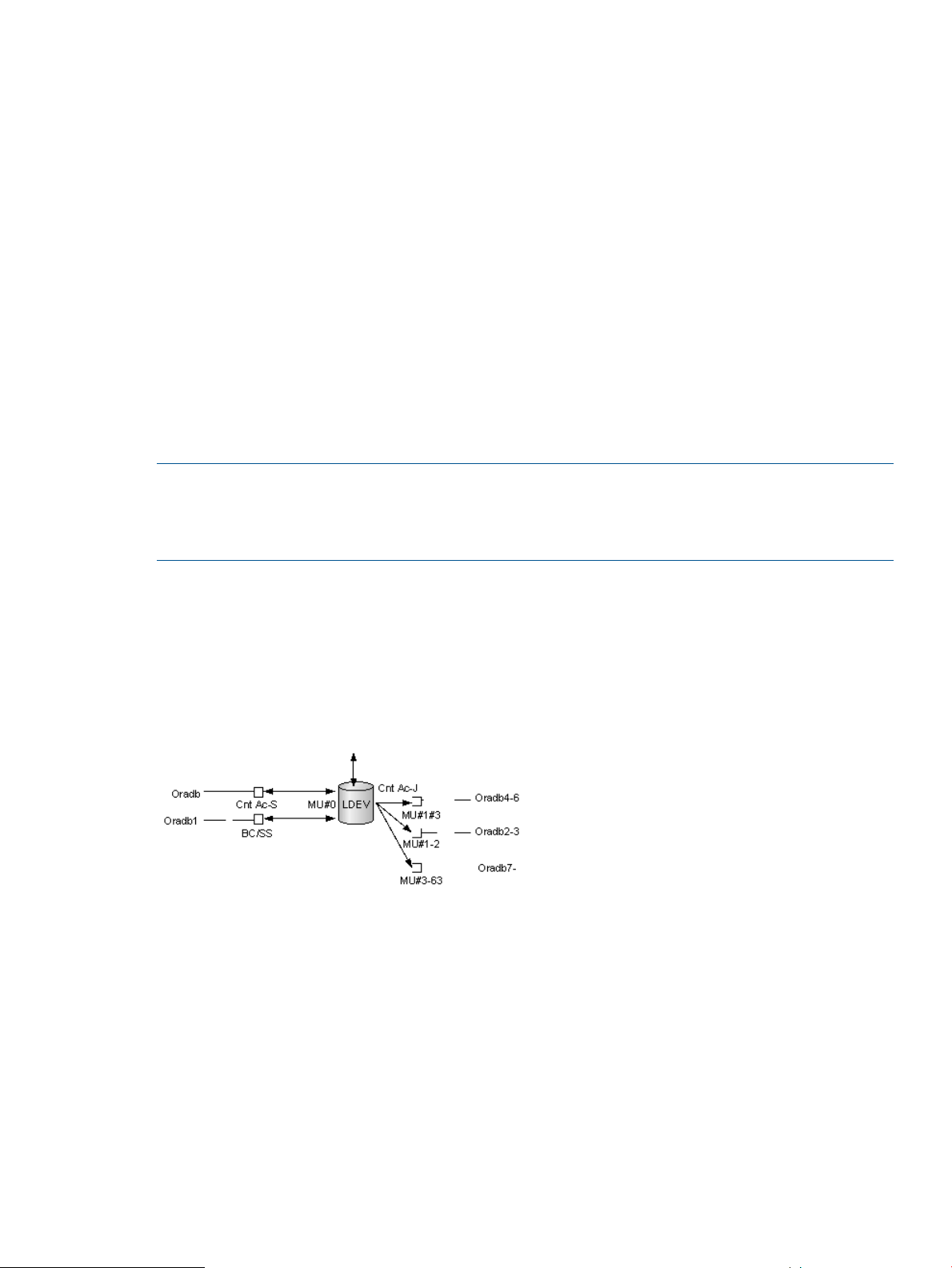
(6) HORCM_LDEVG
The HORCM_LDEVG parameter defines the device group information that the RAID Manager
instance reads. For details about device group, see“LDEV group function” (page 63).
The following values are defined.
• Copy group: specifies a name of copy group. This is equivalent to the dev_group of
HORCM_DEV and HORCM_LDEV parameters.
RAID Manager operates by using the information defined here.
• ldev_group: Specifies a name of device group that the RAID Manager instance reads.
• Serial#: Specifies a DKC serial number.
(7) HORCM_INSTP
The HORCM_INSTP parameter uses when specifying a path ID for the link of Continuous Access
Synchronous as well as HORCM_INST parameter.
HORCM_INSTP
dev_group ip_address service pathID
VG01 HSTA horcm 1
VG02 HSTA horcm 2
NOTE: The path ID can be specified at Continuous Access Synchronous. It cannot be specified
at Cnt Ac-J. Because the path ID is used at the paircreate command and the pairresync
-swapp[s], it must be specified at the both site of P-VOL and S-VOL. If the path ID is not specified,
it is used as a CU free.
Configuration definition for cascading volume pairs
The RAID Manager software (HORCM) is capable of keeping track of up to seven pair associations
per LDEV (1 for Continuous Access Synchronous/Cnt Ac-J, 3 for Cnt Ac-J, 3 for Business
Copy/Snapshot, 1 for Snapshot). By this management, RAID Manager can be assigned to seven
groups per LU that describe seven mirror descriptors for a configuration definition file.
Figure 16 Mirror descriptors and group assignment
Configuration file and mirror descriptors
The group name and MU# described in the HORCM_DEV parameter of a configuration definition
file are assigned the corresponding mirror descriptors, as outlined in Table 5 (page 34). “Omission
of MU#” is handled as MU#0, and the specified group is registered to MU#0 on Business Copy
and Continuous Access Synchronous. Also, the MU# that is noted for HORCM_DEV in Table 5 (page
34) reflects a random numbering sequence (for example, 2, 1, 0).
RAID Manager instance components on the host server 33
Page 34

Table 5 Mirror descriptors and group assignments
HORCM_DEV
#dev_group dev_name port# TargetID LU# MU#
Oradb oradev1 CL1-D 2 1
HORCM_DEV
#dev_group dev_name port# TargetID LU# MU#
Oradb oradev1 CL1-D 2 1
Oradb1 oradev11 CL1-D 2 1 1
Oradb2 oradev21 CL1-D 2 1 2
HORCM_DEV
#dev_group dev_name port# TargetID LU# MU#
Oradb oradev1 CL1-D 2 1
Oradb1 oradev11 CL1-D 2 1 0
Oradb2 oradev21 CL1-D 2 1 1
Oradb3 oradev31 CL1-D 2 1 2
MU#0HORCM_DEV parameter in configuration file
Access
Synchronous/
Cnt Ac-J
Business Copy
(Snapshot) only
Business CopyContinuous
(MU#3-#63)
oradev21
oradev31
Cnt Ac-J
only
MU#1-#3MU#1-#2
--oradev1oradev1
-oradev11oradev1oradev1
-oradev21oradev11oradev1
HORCM_DEV
#dev_group dev_name port# TargetID LU# MU#
Oradb oradev1 CL1-D 2 1 0
HORCM_DEV
#dev_group dev_name port# TargetID LU# MU#
Oradb oradev1 CL1-D 2 1 0
Oradb1 oradev11 CL1-D 2 1 1
Oradb2 oradev21 CL1-D 2 1 2
HORCM_DEV
#dev_group dev_name port# TargetID LU# MU#
Oradb oradev1 CL1-D 2 1
Oradb1 oradev11 CL1-D 2 1 0
Oradb2 oradev21 CL1-D 2 1 h1
Oradb3 oradev31 CL1-D 2 1 h2
Oradb4 oradev41 CL1-D 2 1 h3
Cascading connection and configuration files
A volume of the cascading connection describes entity in a configuration definition file on the same
instance, and classifies connection of volume through the mirror descriptor. Also, in the case of
Continuous Access Synchronous/Business Copy cascading connection, the volume entity describes
to a configuration definition file on the same instance. The following figure shows an example of
this.
--oradev1-
-oradev11oradev1-
oradev21
oradev21-oradev11oradev1
oradev31
oradev41
34 RAID Manager software environment
Page 35

Figure 17 Business Copy cascade connection and configuration file
Business Copy
Since Business Copy is a mirrored configuration within one storage system, it can be described
as a volume of the cascading connection according to two configuration definition files. For a
Business Copy-only cascading connection, the specified group is assigned to the mirror descriptor
(MU#) of Business Copy, specifically defining “0” as the MU# for Business Copy. Figure 18 (page
35) - Figure 20 (page 36) show Business Copy cascading configurations and the pairdisplay
information for each configuration.
Figure 18 Pairdisplay on HORCMINST0
RAID Manager instance components on the host server 35
Page 36
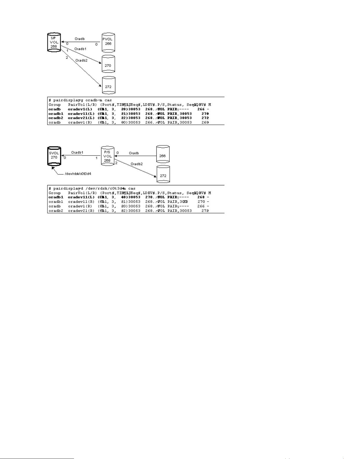
Figure 19 Pairdisplay on HORCMINST1
Figure 20 Pairdisplay on HORCMINST0
Cascading connections for Continuous Access Synchronous and Business Copy
The cascading connections for Continuous Access Synchronous/Business Copy can be set up by
using three configuration definition files that describe the cascading volume entity in a configuration
definition file on the same instance. The mirror descriptor of Business Copy and Continuous Access
Synchronous definitely describe “0” as MU#, and the mirror descriptor of Continuous Access
Synchronous does not describe “0” as MU#.
36 RAID Manager software environment
Page 37
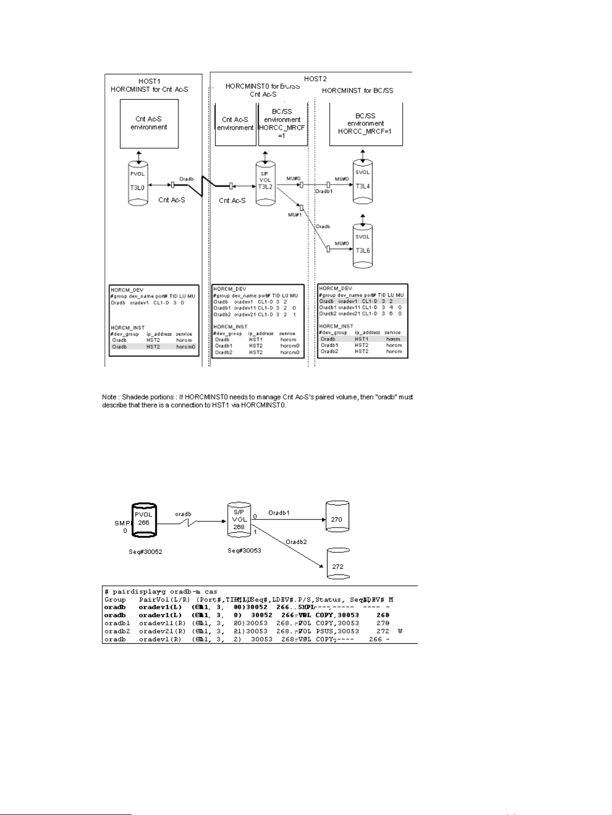
Figure 21 Continuous Access Synchronous/Business Copy cascading connection and configuration
file
Figure 22 (page 37) through Figure 25 (page 38) show Continuous Access Synchronous/Business
Copy cascading configurations and the pairdisplay information for each configuration.
Figure 22 Pairdisplay for Continuous Access Synchronous on HOST1
RAID Manager instance components on the host server 37
Page 38
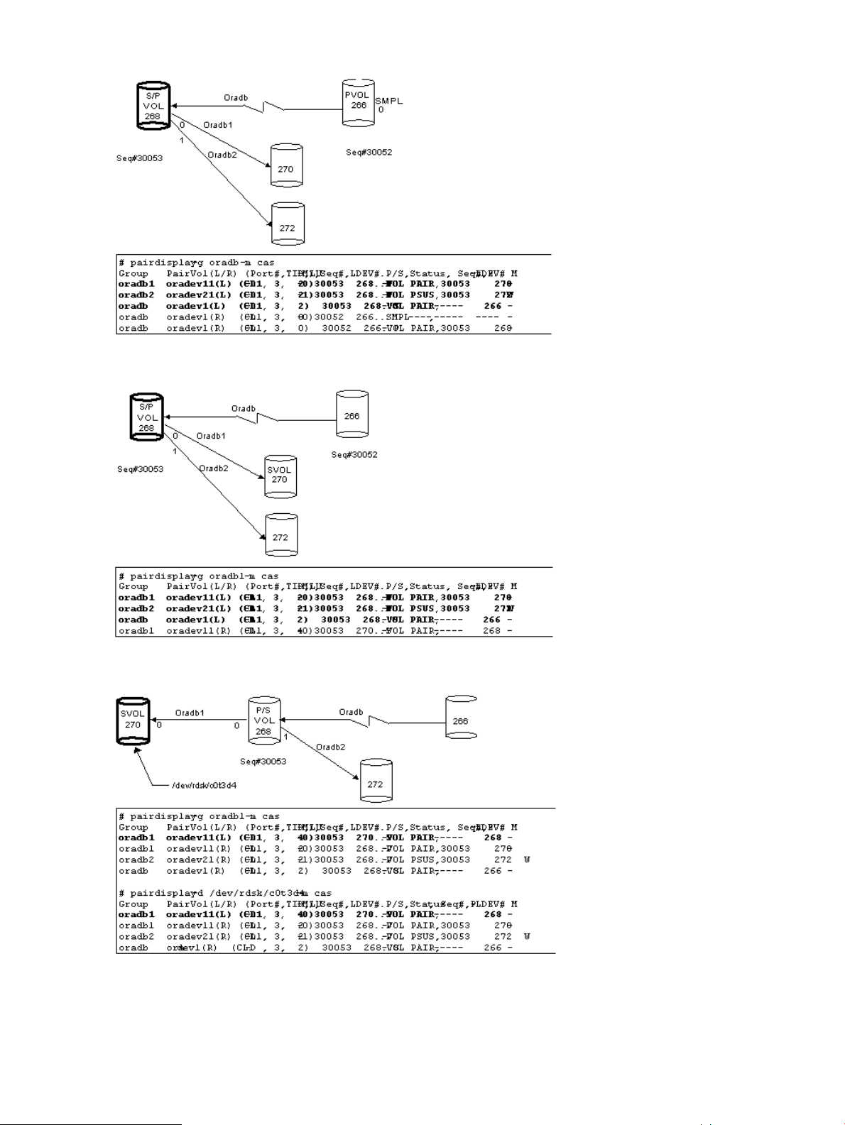
Figure 23 Pairdisplay for Continuous Access Synchronous on HOST2 (HORCMINST)
Figure 24 Pairdisplay for Business Copy on HOST2 (HORCMINST)
Figure 25 Pairdisplay for Business Copy on HOST2 (HORCMINST0)
38 RAID Manager software environment
Page 39

RAID Manager software files
The RAID Manager software consists of files supplied with the software, log files created internally,
and files created by the user. These files are stored on the local disk in the server machine.
• “RAID Manager files supplied with the software” (page 39)
• “RAID Manager log and trace files” (page 42)
• “User-created files” (page 46)
RAID Manager files supplied with the software
• “RAID Manager files for UNIX-based systems” (page 39)
• “RAID Manager files for Windows-based systems” (page 40)
• “RAID Manager files for OpenVMS-based systems” (page 41)
RAID Manager files for UNIX-based systems
GroupUser*1ModeCommand nameFile nameTitle
sysroot0544horcmd/etc/horcmgrHORCM
sysroot0444-/HORCM/etc/horcm.confHORCM_CONF
sysroot0544horctakeover/usr/bin/horctakeoverTakeover
sysroot0544paircurchk/usr/bin/paircurchkAccessibility check
sysroot0544paircreate/usr/bin/paircreatePair generation
sysroot0544pairsplit/usr/bin/pairsplitPair splitting
sysroot0544pairresync/usr/bin/pairresyncPair resynchronization
sysroot0544pairevtwait/usr/bin/pairevtwaitEvent waiting
sysroot0544pairmon/usr/bin/pairmonError notification
sysroot0544pairvolchk/usr/bin/pairvolchkVolume check
sysroot0544pairdisplay/usr/bin/pairdisplayPair configuration confirmation
sysroot0544raidscan/usr/bin/raidscanRAID scanning
sysroot0544raidar/usr/bin/raidarRAID activity reporting
sysroot0544raidqry/usr/bin/raidqryConnection confirming
sysroot0544horcctl/usr/bin/horcctlTrace control
sysroot0544horcmstart.sh/usr/bin/horcmstart.shHORCM activation script
sysroot0544horcmshutdown.sh/usr/bin/horcmshutdown.shHORCM shutdown script
sysroot0544--/HORCM/usr/bin/inqraidConnection confirming
sysroot0544pairsyncwait/usr/bin/pairsyncwaitSynchronous waiting
confirmation
confirmation
sysroot0544--/HORCM/usr/bin/mkconf.shConfiguration file making
sysroot0544raidvchkset/usr/bin/raidvchksetDatabase Validator setting
sysroot0544raidvchkdsp/usr/bin/raidvchkdspDatabase Validator
sysroot0544raidvchkscan/usr/bin/raidvchkscanDatabase Validator
sysroot0544rmsra/HORCM/usr/bin/rmsraStorage Replication Adapter
RAID Manager software files 39
Page 40

NOTE:
• The \HORCM\etc\ commands are used from the console window. If these commands are
executed without an argument, the interactive mode will start up.
• The \HORCM\usr\bin commands have no console window, and can therefore be used from
the application.
• The \HORCM\usr\bin commands do not support the directory mounted volumes in
subcommands.
For information and instructions on changing the UNIX user for the RAID Manager software, please
see the HP StorageWorks P9000 RAID Manager Installation and Configuration User Guide.
RAID Manager files for Windows-based systems
GroupUser*1ModeCommand nameFile nameTitle
sysroot0544raidcomHORCM/usr/bin/raidcomConfiguration setting command
sysroot0644-HORCM/etc/Raidcom_Dic_Raid_RMXP_Patch.txtA file for management
sysroot0644-HORCM/etc/Raidcom_Help_Raid_RMXP.txtA file for management
sysroot0644-HORCM/etc/Raidcom_Dic_Raid_RMXP.txtA file for management
Command nameFile nameTitle
horcmd\HORCM\etc\horcmgr.exeHORCM
-\HORCM\etc\horcm.confHORCM_CONF
horctakeover\HORCM\etc\horctakeover.exeTakeover
paircurchk\HORCM\etc\paircurchk.exeAccessibility check
paircreate\HORCM\etc\paircreate.exePair generation
pairsplit\HORCM\etc\pairsplit.exePair split
pairresync\HORCM\etc\pairresync.exePair re-synchronization
pairevtwait\HORCM\etc\pairevtwait.exeEvent waiting
pairmon\HORCM\etc\pairmon.exeError notification
pairvolchk\HORCM\etc\pairvolchk.exeVolume checking
pairdisplay\HORCM\etc\pairdisplay.exePair configuration confirmation
raidscan\HORCM\etc\raidscan.exeRAID scanning
raidar\HORCM\etc\raidar.exeRAID activity reporting
raidqry\HORCM\etc\raidqry.exeConnection confirmation
horcctl\HORCM\etc\horcctl.exeTrace control
horcmstart\HORCM\etc\horcmstart.exeHORCM activation script
40 RAID Manager software environment
horcmshutdown\HORCM\etc\horcmshutdown.exeHORCM shutdown script
pairsyncwait\HORCM\etc\pairsyncwait.exeSynchronous waiting
inqraid\HORCM\etc\inqraid.exeConnection confirmation
mkconf\HORCM\Tool\mkconf.exeConfiguration file making
raidvchkset\HORCM\etc\raidvchkset.exeOracle Validation setting
Page 41

Command nameFile nameTitle
raidvchkdsp\HORCM\etc\raidvchkdsp.exeOracle Validation confirmation
raidvchkscan\HORCM\etc\raidvchkscan.exeOracle Validation confirmation
raidcom\HORCM\etc\raidcom.exeConfiguration setting command
-\HORCM\etc\Raidcom_Dic_Raid_RMXP_Patch.txtA file for management
-\HORCM\etc\Raidcom_Help_Raid_RMXP.txtA file for management
-\HORCM\etc\Raidcom_Dic_Raid_RMXP.txtA file for management
chgacl\HORCM\Tool\chgacl.exeTool
svcexe\HORCM\Tool\svcexe.exeTool
-\HORCM\Tool\HORCM0_run.txtSample script for svcexe
TRCLOG\HORCM\Tool\TRCLOG.batTool
rmsra\HORCM\etc\rmsra.exeStorage Replication Adapter
horctakeover\HORCM\usr\bin\horctakeover.exeTakeover
paircurchk\HORCM\usr\bin\paircurchk.exeAccessibility check
paircreate\HORCM\usr\bin\paircreate.exePair generation
pairsplit\HORCM\usr\bin\pairsplit.exePair split
RAID Manager files for OpenVMS-based systems
pairresync\HORCM\usr\bin\pairresync.exePair re-synchronization
pairevtwait\HORCM\usr\bin\pairevtwait.exeEvent waiting
pairvolchk\HORCM\usr\bin\pairvolchk.exeVolume check
pairsyncwait\HORCM\usr\bin\pairsyncwait.exeSynchronous waiting
pairdisplay\HORCM\usr\bin\pairdisplay.exePair configuration confirmation
raidscan\HORCM\usr\bin\raidscan.exeRAID scanning
raidqry\HORCM\usr\bin\raidqry.exeConnection confirmation
raidvchkset\HORCM\usr\bin\raidvchkset.exeOracle Validation setting
raidvchkdsp\HORCM\usr\bin\raidvchkdsp.exeOracle Validation confirmation
raidvchkscan\HORCM\usr\bin\raidvchkscan.exeOracle Validation confirmation
raidcom\HORCM\usr\bin\raidcom.exeConfiguration setting command
UserCommand nameFile nameTitle
syshorcmd$ROOT:[HORCM.etc]horcmgr.exeHORCM
sys-$ROOT:[HORCM.etc]horcm.confHORCM_CONF
syshorctakeover$ROOT:[HORCM.usr.bin]horctakeover.exeTakeover
syspaircurchk$ROOT:[HORCM.usr.bin]paircurchk.exeVolume Accessibility check
syspaircreate$ROOT:[HORCM.usr.bin]paircreate.exePair generation
syspairsplit$ROOT:[HORCM.usr.bin]pairsplit.exePair splitting
syspairresync$ROOT:[HORCM.usr.bin]pairresync.exePair re-synchronization
syspairevtwait$ROOT:[HORCM.usr.bin]pairevtwait.exeEvent waiting
RAID Manager software files 41
Page 42

confirmation
confirmation
UserCommand nameFile nameTitle
syspairmon$ROOT:[HORCM.usr.bin]pairmon.exeError notification
syspairvolchk$ROOT:[HORCM.usr.bin]pairvolchk.exeVolume checking
syspairdisplay$ROOT:[HORCM.usr.bin]pairdisplay.exePair configuration
sysraidscan$ROOT:[HORCM.usr.bin]raidscan.exeRAID scan
sysraidar$ROOT:[HORCM.usr.bin]raidar.exeRAID activity report
sysraidqry$ROOT:[HORCM.usr.bin]raidqry.exeConnection confirmation
syshorcctl$ROOT:[HORCM.usr.bin]horcctl.exeTrace control
syshorcmstart.sh$ROOT:[HORCM.usr.bin]horcmstart.exeHORCM activation script
syshorcmshutdown.sh$ROOT:[HORCM.usr.bin]horcmshutdown.exeHORCM shutdown script
sys-$ROOT:[HORCM.usr.bin]inqraid.exeConnection confirmation
syspairsyncwait$ROOT:[HORCM.usr.bin]pairsyncwait.exeSynchronous waiting
sys-$ROOT:[HORCM.usr.bin]mkconf.exeConfiguration file making
sysraidvchkset$ROOT:[HORCM.usr.bin]raidvchkset.exeDatabase Validator setting
sysraidvchkdsp$ROOT:[HORCM.usr.bin]raidvchkdsp.exeDatabase Validator
confirmation
NOTE:
• $ROOT is defined as SYS$POSIX_ROOT. $POSIX_ROOT is necessary when using C RTL.
• The user name for OpenVMS is “System”.
RAID Manager log and trace files
The RAID Manager software (HORCM) maintains internal startup log files, execution log files, and
trace files that can be used to identify the causes of errors and to keep records of the status transition
history of the paired volumes.
• “RAID Manager log files” (page 42)
• “RAID Manager trace files” (page 44)
• “RAID Manager trace control command” (page 44)
• “Command error logging for audit” (page 45)
sysraidvchkscan$ROOT:[HORCM.usr.bin]raidvchkscan.exeDatabase Validator
sysrmsra$ROOT:[HORCM.usr.bin]rmsra.exeStorage Replication Adapter
sys-$ROOT:[HORCM]loginhorcm*.comSample file for horcmstart
sys-$ROOT:[HORCM]runhorcm*.comSample file for horcmstart
RAID Manager log files
HORCM logs are classified into startup logs and execution logs. The startup logs contain data on
errors that occur before the HORCM becomes ready to provide services. Thus, if the HORCM fails
to start up due to improper environment setting, see the startup logs to resolve the problem. The
HORCM execution logs (error log, trace, and core files) contain data on errors that are caused
by software or hardware problems. These logs contain internal error data that does not apply to
any user settings, therefore, you do not need to see the HORCM execution logs. When an error
42 RAID Manager software environment
Page 43

occurs in execution of a command, data on the error is collected in the command log file. Users
may see the command log file if a command execution error occurs. The following figure shows
a graphical understanding of the RAID Manager log and trace files within the RAID Manager
configuration environment.
Figure 26 Logs and traces
The startup log, error log, trace, and core files are stored as shown in Table 6 (page 43). Specify
the directories for the HORCM and command log files using the HORCM_LOG and HORCC_LOG
environment variables as shown in Table 7 (page 44). If it is not possible to create the log files,
or if an error occurs before the log files are created, the error logs are output in the system log
file. If the HORCM activation fails, the system administrator should check the system log file, identify
the error cause, and take the proper action. The system log file for UNIX-based systems is the syslog
file. The system log file for Windows-based systems is the Event Log file.
Table 6 Log file names and locations
Windows-based systemsUNIX-based systemsFile
HORCM startup log:HORCM startup log:startup log
$HORCM_LOG\horcm_HOST_log.txt$HORCM_LOG/horcm_HOST.log
Command log: $HORCC_LOG\horcc_HOST_log.txtCommand log: $HORCC_LOG/horcc_HOST.log
$HORCC_LOG\horcc_HOST_oldlog.txt$HORCC_LOG/horcc_HOST.oldlog
HORCM error log:HORCM error log:Error log
$HORCM_LOG\horcmlog_HOST\horcm_log.txt$HORCM_LOG/horcmlog_HOST/horcm.log
HORCM trace:HORCM trace:Trace
$HORCM_LOG\horcmlog_HOST\horcm_PID_trc.txt$HORCM_LOG/horcmlog_HOST/horcm_PID.trc
Command trace:Command trace:
$HORCM_LOG\horcmlog_HOST\horcc_PID_trc.txt$HORCM_LOG/horcmlog_HOST/horcc_PID.trc
$HORCM_LOG/core_HOST_PID/core
HORCM core: $HORCM_LOG\core_HOST_PID\coreHORCM core:Core
Command core:$HORCM_LOG/core_HOST_PID/core
$HORCM_LOG\core_HOST_PID\coreCommand core:
RAID Manager log and trace files 43
Page 44

NOTE: HOST denotes the host name of the corresponding machine. PID denotes the process ID
of that machine.
The location of the directory containing the log file depends on your command execution environment
and the HORCM execution environment. The command trace file and core file reside together
under the directory specified in the HORCM execution environment. A directory specified using
the environment variable HORCM_LOG is used as the log directory in the HORCM execution
environment. If no directory is specified, the directory /tmp is used. A directory specified using
the environment variable HORCC_LOG is used as the log directory in the command execution
environment. If no directory is specified, the directory /HORCM/log* is used (* = instance number).
A nonexistent directory may be specified as a log directory using the environment variable.
Table 7 Environment variables for log directories
DefinitionDirectory name
$HORCM_LOG
$HORCC_LOG
A directory specified using the environment variable HORCM_LOG. The HORCM log file, trace file, and
core file as well as the command trace file and core file are stored in this directory. If no environment variable
is specified, “/HORCM/log/curlog” is used.
A directory specified using the environment variable HORCC_LOG. The command log file is stored in this
directory. If no environment variable is specified, the directory “/HORCM/log*” is used (* is the instance
number). While the HORCM is running, the log files are stored in the $HORCM_LOG directory shown in
(a). When the HORCM starts up, the log files created in the operation are stored automatically in the
$HORCM_LOGS directory shown in (b).
a. HORCM log file directory in operation
$HORCM_LOG = /HORCM/log*/curlog (* is instance number)
b. HORCM log file directory for automatic storing
$HORCM_LOGS = /HORCM/log*/tmplog (* is instance number)
RAID Manager trace files
The command trace file is used for maintenance aiming at troubleshooting. It is not created normally.
If a cause of an error cannot be identified using the log file, the environment variables or trace
control commands with trace control parameters are issued to start tracing and the trace file is
created. The trace control parameters include trace level, file size, mode, etc. More detailed tracing
is enabled by increasing the trace level. Tracing is made in wraparound within the range of the
file size. HORCM makes the trace file according to the trace level specified in the HORCM startup
shell script set to activate the HORCM.
RAID Manager trace control command
The trace control command (one of the HORCM control commands) sets or changes the trace
control parameters. This command is used for troubleshooting and maintenance. If no trace control
parameters can be specified using the environment variables in your command execution
environment, it is possible to change the trace control parameters into the global parameters using
this command. Table 8 (page 44) lists and describes the parameters of the trace control command.
Table 8 Trace command parameters
FunctionParameter
Specifies the trace level, range = 0 to 15.Trace level parameter
Specifies the trace file size in KB.Trace size parameter
Specifies the buffer mode or non-buffer mode for writing data in the trace file.Trace mode parameter
44 RAID Manager software environment
Page 45

Table 8 Trace command parameters (continued)
FunctionParameter
Specifies the trace type defined internally.Trace type parameter
Trace change instruction
Specifies the command or RAID Manager instance for which the trace control parameters
are changed.
Command error logging for audit
RAID Manager supports command error logging only, so this logging function cannot be used for
auditing the script issuing the command. Thus, RAID Manager supports the function logging the
result of the command executions by expanding the current logging.
This function has the following control parameters.
• $HORCC_LOGSZ variable
This variable is used to specify a maximum size (in units of KB) and normal logging for the
current command. /HORCM/log*/horcc_HOST.log file is moved to
/HORCM/log*/horcc_HOST.old log file when reaching in the specified maximum size. If
this variable is not specified or specified as 0, it is same as the current logging for only
command error.
This variable is able to define to the environment variable and/or horcc_HOST.conf as
discussed below.
For example setting 2MB size: HORCC_LOGSZ=2048 Export HORCC_LOGSZ
• /HORCM/log*/horcc_HOST.conf file
This file is used to describe HORCC_LOGSZ variable and the masking variable for logging.
If the HORCC_LOGSZ as the environment variable is not specified, then HORCC_LOGSZ
variable of this file is used. If both variable is not specified, then it is same as the current
logging for only command error.
• HORCC_LOGSZ variable
This variable must be described as follows: HORCC_LOGSZ=2048
• The masking variable
This variable is used to mask (disable) the logging by specifying a condition of the command
and exit code (except inqraid or EX_xxx error code). This variable is valid for NORMAL exit.
If executing the pairvolchk command repeatedly at every interval (i.e., 30 sec), logging
of this command may not be wanted. Therefore, you can mask it by specifying
HORCC_LOGSZ=0 as below, however you may need to change your scripts if tracing is ON.
Example of masking pairvolchk on a script:
Export HORCC_LOGSZ=0 Pairvolchk -g xxx -s Unset HORCC_LOGSZ
The masking feature is to enable the tracing without changing their scripts. And this feature
is available for all RAID Manager commands (except inqraid or EX_xxx error code).
For example, if you want to mask pairvolchk (returns 22) and raidqry, specify the following:
pairvolchk=22 raidqry=0
RAID Manager log and trace files 45
Page 46

You can track script performance, and then decide to mask by auditing the command logging
file, as needed.
• Relationship between an environment variable and horcc_HOST.conf
Logging depends on the $HORCC_LOGSZ environment variable and/or the
HORCC_HOST.conf file as shown below.
PerformingHORCC_HOST.conf$HORCC_LOGSZ
Tracing within this APPDon't care=value
NO tracing within this APP=0
Global Tracing within this RAID Manager instanceHORCC_LOGSZ=valueUnspecified
HORCC_LOGSZ=0
Unspecified or Nonexistent
Global NO tracing within this RAID Manager
instance
Use the default value (0) The same as the current
logging for only command error
• Examples for execution
/HORCM/log* directory
[root@raidmanager log9]# ls l
total 16
drwxr-xr-x 3 root root 4096 Oct 27 17:33 curlog
-rw-r--r-- 1 root root 3936 Oct 27 17:36 horcc_raidmanager.log
-rw-r--r-- 1 root root 2097452 Oct 27 17:29 horcc_raidmanager.oldlog
-rw-r--r-- 1 root root 46 Oct 27 17:19 horcc_raidmanager.conf
drwxr-xr-x 3 root root 4096 Oct 27 17:19 tmplog
/HORCM/log*/horcc_HOST.log file
COMMAND NORMAL : EUserId for HORC : root (0) Tue Nov 1 12:21:53 2005
CMDLINE : pairvolchk ss g URA
12:21:54-2d27f-10090- [pairvolchk][exit(32)]
COMMAND NORMAL : EUserId for HORC : root (0) Thu Oct 27 17:36:32 2005
CMDLINE : raidqry l
17:36:32-3d83c-17539- [raidqry][exit(0)]
COMMAND ERROR : EUserId for HORC : root (0) Thu Oct 27 17:31:28 2005
CMDLINE : pairdisplay g UR
17:31:28-9a206-17514- ERROR:cm_sndrcv[rc < 0 from HORCM]
17:31:28-9b0a3-17514- [pairdisplay][exit(239)]
[EX_ENOGRP] No such group
[Cause ]:The group name which was designated or the device name doesn't exist in the configuration
file, or the network address for remote communication doesn't exist.
[Action]:Please confirm if the group name exists in the
configuration file of the local and remote host
/HORCM/log*/horcc_HOST.conf file
# For Example
HORCC_LOGSZ=2048
#The masking variable
#This variable is used to disable the logging by the command and exit code.
#For masking below log pairvolchk returned '32'(status is S-VOL_COPY)
#COMMAND NORMAL : EUserId for HORC : root (0) Tue Nov 1 12:21:53 2005
#CMDLINE : pairvolchk ss g URA
#12:21:54-2d27f-10090- [pairvolchk][exit(32)]
pairvolchk=32
pairvolchk=22
User-created files
RAID Manager supports scripting to provide automated and unattended copy operations. A RAID
Manager script contains a list of RAID Manager commands that describes a series of Continuous
Access Synchronous and/or Business Copy operations. The scripted commands for UNIX-based
platforms are defined in a shell script file. The scripted commands for Windows-based platforms
46 RAID Manager software environment
Page 47

are defined in a text file. The host reads the script file and sends the commands to the command
device to execute the Continuous Access Synchronous/Business Copy operations automatically.
The RAID Manager scripts are:
• HORCM startup script (horcmstart.sh, horcmstart.exe). A script that starts HORCM
(/etc/horcmgr), sets environment variables as needed (e.g., HORCM_CONF, HORCM_LOG,
HORCM_LOGS), and starts HORCM.
• HORCM shutdown script. (horcmshutdown.sh, horcmshutdown.exe): A script for stopping the
HORCM (/etc/horcmgr).
• HA control script. A script for executing takeover processing automatically when the cluster
manager (CM) detects a server error.
When constructing the HORCM environment, the system administrator should make a copy of the
horcm.conf file. The copied file should be set according to the system environment and registered
as the following file (* is the instance number):
UNIX systems: /etc/horcm.conf or /etc/horcm*.conf
Windows systems:\WINNT\horcm.conf or \WINNT\horcm*.conf
User-created files 47
Page 48

3 RAID Manager functions on P9500
The RAID Manager functions available on the P9500 storage system are more comprehensive than
on previous RAID storage systems.
Command execution using in-band and out-of-band methods
The methods of executing commands provided by RAID Manager can be classified into the in-band
and out-of-band methods.
• In-band method. This method transfers a command from the client or the server to the command
device of the storage system via Fibre and executes a RAID Manager operation instruction.
• Out-of-band method. This method transfers a command from the client or the server to the
virtual command device in the SVP via LAN, assigning a RAID Manager operation instruction
to the storage system, and executes it.
For the out-of-band method, an IP address of the SVP is specified in the configuration definition
file.
The following figure shows a system configuration example and a setting example of a command
device and a virtual command device using the in-band and out-of-band methods.
Figure 27 System configuration example and setting example of command device and virtual
command device by in-band and out-of-band methods
To set these two methods, a command device or a virtual command device must be set to
HORCM_CMD of a configuration definition file.
48 RAID Manager functions on P9500
Page 49

When executing a command using the in-band method, set an LU path in a configuration definition
file and create a command device. The command device in the storage system specified by the
LU path accepts the command from the client, and executes the operation instruction.
When executing a command using the out-of-band method, create a virtual command device. The
virtual command device is created by specifying an IP address of the SVP, a UDP communication
port number, and a storage system unit number in the configuration definition file.
See ??? for details of the contents to be defined to HORCM_CMD.
User authentication
RAID Manager allows user authentication by using the user information managed by Remote Web
Console and the SVP.
User authentication is arbitrary in the Replication operation in the in-band method while the operation
by user authentication is mandatory in the configuration information operation and in the out-of-band
method.
To enable the user authentication function, the user authentication mode of the command device
accessed by RAID Manager must be enabled.
The user authentication function inputs a login command from the client (server) and, to authenticate
the user ID and password sent from RAID Manager and the same types of information maintained
by the storage system, issues an authentication request to the authentication module (SVP).
If the user ID and password sent from RAID Manager are authenticated, RAID Manager, for the
once authenticated user (the user on the client starting up RAID Manager), stores the user ID and
password. This saves the necessity of inputting the user ID and password each time a command
is executed. If the user logs out, the user ID and password stored by RAID Manager are deleted.
If the user ID and password are different, the command is rejected and RAID Manager automatically
performs the logout processing for it, and requires the user authentication processing (user ID and
password input) again.
NOTE:
• The only function that can be used if the user authentication function is disabled is the
Replication function (replication command). If the user authentication function is disabled, the
Provisioning function (configuration setting command) cannot be used.
• If specific user information or authority information is changed, delete the user ID and password
maintained by the storage system from the SVP. Therefore, perform the user authentication
processing on RAID Manager again.
• If the communication with the SVP in the out-band method cannot be performed, the new
authentication cannot be performed.
Command operation authority and user authentication
If RAID Manager is operated with the user authentication function enabled, commands are executed
complying with the operation authority managed by Remote Web Console and the SVP.
Controlling User Role
RAID Manager verifies whether or not the user executing the command on the host was already
authenticated by checking the command device being in the authentication mode. After that, RAID
Manager obtains the execution authority of the command that is configured on the user role, and
then compares the relevant command and the execution authority.
User authentication 49
Page 50

Checking the execution authority
If the configuring commands authenticated are compared with the execution authorities of commands
configured on the user role and they do not correspond, RAID Manager rejects the command with
an error code "EX_EPPERM".
Normally, the user role needs to be the consistent and integrated authority among the large storage
systems. In case of HORCM instances that are configured by the multiple large storage systems,
the execution authorities are obtained by the serial number of the storage systems. If the user role
is for the multiple storage systems and is not consistent among these storage systems, RAID Manager
makes the integrated authority by performing the logical AND of the execution authorities among
the storage systems.
The target commands
RAID Manager checks execution authorities on the following commands that use command devices.
• horctakeover, horctakeoff
• paircreate, pairsplit, pairresync
• raidvchkset
Controlling user resources
RAID Manager verifies the user who executes the command has been authenticated already. After
that, RAID Manager obtains the access authority of the resource groups that are configured on the
user roles, and then compares the access authority of the relevant user and the specified resources.
Checking resource authorities
If the access is not permitted by comparing the access authorities of the resource groups configured
on the user roles and the specified resource, RAID Manager rejects the command with an error
code "EX_EGPERM". If the resource groups are defined among the large storage systems, the
specified resource is compared with the resource specified by obtaining the access authority
configured to each large storage system.
Target commands
RAID Manager checks resource authorities on the following commands that use command devices.
• raidcom commands (commands for setting configurations)
• horctakeover, horctakeoff, paircurchk, paircreate, pairsplit, pairresync, pairvolchk, pairevtwait,
pairsyncwait, pairmon
• raidscan (-find verify, -find inst, -find sync except for [d]), pairdisplay, raidar, raidqry (except
for -l and -r)
• raidvchkset, raidvchkscan (except for -v jnl), raidvchkdsp
The relationship between the user authentication and the resource groups
In user authentication mode, RAID Manager verifies the access authority of the relevant resource
based on the user authentication and the role of it. Also, on the user authentication unnecessary
mode and the undefined resource groups, RAID Manager checks the access authorities shown in
the following table.
50 RAID Manager functions on P9500
Page 51

Table 9 The relationship between the resource groups and the command devices
CommandsResource Groups
raidcompairXX*1
Authenticated userNot authenticated
user*2
*3
group
Defined resource
group
*1
: Above-described commands except for the raidcom command
*2
: User who uses the mode without the command authentication
*3
: Undefined as the resource group
*4
: Command execution is rejected by the relevant error
PermittedUndefined resource
EX_EGPERM
*4
Permitted by the
authority of resource
ID 0
Permitted by the
authority of the
relevant resource ID
user*2
EX_EPPERM
EX_EGPERM
EX_EPPERM
*4
*4
Authenticated userNot authenticated
Permitted by the
authority of resource
ID 0
Permitted by the
authority of the
relevant resource ID
Target resources
The following objects are arbitrarily defined as the resource groups by each user.
• LDEV
• Physical port
• Host group
• RAID group
• External connection group
The commands that are executed depending on the operation authorities managed by Remote Web Console and the SVP
The commands and operation authority managed by Remote Web Console and SVP are listed in
the following table.
For information about creating the Remote Web Console user accounts, registering user accounts
to user groups, and user group authorities, see HP StorageWorks P9000 Remote Web Console
User Guide.
Table 10 Commands and operation authority managed by Remote Web Console and SVP
Executable commandAuthorityOperation targetOperation
MP blade setting authorityMP bladeSetting (entire apparatus)
LDEVResource creation, deletion
raidcom add ldev
• raidcom modify ldev
• raidcom modify journal
• raidcom modify
external_grp
raidcom add ldevLDEV creation authority
raidcom delete ldevLDEV deletion authority
Command operation authority and user authentication 51
Page 52

Table 10 Commands and operation authority managed by Remote Web Console and SVP (continued)
Executable commandAuthorityOperation targetOperation
External volume (External
Storage)
Pool
Thin Provisioning virtual volume
External volume creation
authority
External path operation
authority
External volume disconnection
authority
External volume connection
check and resumption authority
release authority
Pool creation and capacity
change authority
creation authority
deletion authority
• raidcom add external_grp
• raidcom discover
external_storage
• raidcom discover lun
• raidcom check_ext_storage
path
• raidcom disconnect path
• raidcom check_ext_storage
external_grp
• raidcom disconnect
external_grp
raidcom delete external_grpExternal volume mapping
• raidcom add thp_pool
• raidcom add snap_pool
raidcom delete poolPool deletion authority
raidcom add ldev -poolThin Provisioning virtual volume
raidcom delete ldevThin Provisioning virtual volume
Snapshot virtual volume
LDEV group
creation authority
deletion authority
LUN security setting authorityPort
creation authority
deletion authority
raidcom add ldev -poolSnapshot virtual volume
raidcom delete ldevSnapshot virtual volume
raidcom modify port
-security_switch
raidcom add host_grpHost group creation authorityHost group
raidcom delete host_grpHost group deletion authority
raidcom add lunLU path creation authorityLUN
raidcom delete lunLU path deletion authority
raidcom add hba_wwnWWN addition authorityWWN
raidcom delete hba_wwnWWN deletion authority
raidcom add device_grpDevice group and Copy group
raidcom add copy_grp
raidcom delete device_grpDevice group and Copy group
raidcom delete copy_grp
paircreatePair creation authorityLocal copy
52 RAID Manager functions on P9500
pairsplit -SPair deletion authority
paircreateAuto LUN pair creation
authority
Page 53

Table 10 Commands and operation authority managed by Remote Web Console and SVP (continued)
Executable commandAuthorityOperation targetOperation
pairsplit -SAuto LUN pair deletion
authority
paircreatePair creation authorityRemote copy
pairsplit -SPair deletion authority
raidcom add pathExternal path setting authorityExternal VolumeAttribute change
raidcom modify poolPool setting authorityPool
LDEV nickname
Remote copy
Port attribute setting authorityPort
Port setting authority
WWN setting authorityWWN
LDEV nickname setting
authority
Environment construction
authority
raidcom modify port
-port_attribute
• raidcom modify port
-loop_id
• raidcom modify port
-topology
• raidcom modify port
-port_speed
raidcom add host_grpHost group setting authorityHost group
• raidcom set hba_wwn
• raidcom reset hba_wwn
raidcom modify ldev
-ldev_name
pairresyncPairsplit and resync authorityLocal copy
• raidcom add rcu
• raidcom delete rcu
• raidcom modify rcu
• raidcom add rcu_path
• raidcom delete rcu_path
• raidcom add journal
• raidcom delete journal
• raidcom modify journal
pairresyncPairsplit and resync authority
The relationship between resource groups and command operations
The operation for using resource groups are different by the command devices (the In-Band method)
or the Out-of-Band method that are used when you start RAID Manager.
You can create resource groups for each resource. And you can share them with multiple users.
When user 10 and user 20 share the port like the following figure, the relation between the
command devices and resource groups that user can use is like Table 11 (page 54).
The relationship between resource groups and command operations 53
Page 54
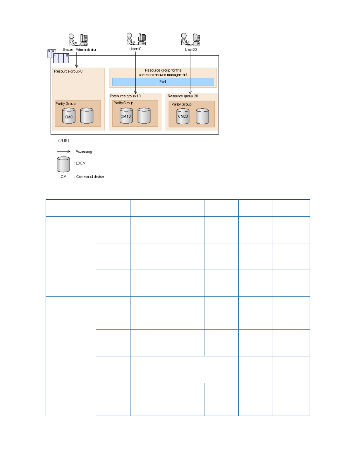
Figure 28 The relationship among user, command devices, and resource groups
Table 11 The relationship between resource groups and command devices
Login user
device
Can operate all resource
groups.
Can operate only in the range
of resource group 10.
Can operate only in the range
of resource group 20.
Can operate in the range of
resource group 10 and shared
ports.
Can operate only in the range
of resource group 10.
ReferenceOperating rangeCommand
change
Out-of-BandConfiguration
OKOKOKOK:CM0System administrator
-OKOKOK:CM10
-OKOKOK:CM20
OKOKOKOK:CM0User 10
-OKOKOK:CM10
CM20
54 RAID Manager functions on P9500
NG:
Nothing is displayed or the operation authority
error.
Can operate in the range of
resource group 20 and shared
ports.
-Operation
authority
error
OKOKOKOK:CM0User 20
Page 55

Table 11 The relationship between resource groups and command devices (continued)
Login user
device
CM10
ReferenceOperating rangeCommand
NG:
Nothing is displayed or the operation authority
error.
Can operate only in the range
of resource group 20.
change
authority
error
Out-of-BandConfiguration
-Operation
-OKOKOK:CM20
OK: Operable
NG: Inoperable
Shown in above table, the relationship among users, command devices, and operations of resource
groups are the following.
• The range that can be operated by command device 0 (CM0) or Out-of-Band is the shared
range (AND) of resource groups that are allocated to each user and all resource groups.
• The range that can be operated by command device 10 (CM10) is the shared range (AND)
of resource groups that are allocated to each user and resource group 10 that the command
devices are allocated.
Therefore, in the range of resource group 10 can be operated.
The following shows the example of the case that the execution results of the commands change
by the case of having or not having the authority of the operated resources, specifies only the
objects or specifies to the parameters.
When user has the authority using CL1-A, CL3-A and CL5-A ports, and CL1-A, CL2-A, CL3-A, CL4-A
and CL5-A ports are implemented in the system, executes the following command.
When only the objects are specified:
# raidcom get port
The execution results of CL1-A, CL3-A and CL5-A are displayed. The execution results of CL2-A
and CL4-A (the user does not have the authority of the resource) are not displayed (filtered).
When parameters are also specified:
# raidcom get port -port CL1-A
The execution result of CL1-A is only displayed.
# raidcom get port -port CL2-A
The error is displayed because the user does not have the execution authority.
The following shows the output example when -cnt that is used in get ldev is used.
The following command is executed when the user has the authorities of LDEV number 10 and 12.
# raidcom get ldev -ldev_id 10 -cnt 3
Execution results of LDEV number 10 and 12 are displayed. LDEV number 11 is not displayed
because the user does not have the authority of the resource.
Resource lock function
When the configuration changes from multiple RAID Manager, SVP, or Remote Web Console are
done to the same resource, unexpected change is executed on each other and it might not be
configure the expected configuration.
To prevent from the changing configuration for the same resource by each of the users, the resource
lock command is provided. When this command is used, the resource group can be locked for
the other users so that they cannot use the specified resource group. And even if the lock is not
Resource lock function 55
Page 56

performed, each configuration change command can be performed. However, the competition
with the other application might cause an error.
The commands for performing the exclusive control and exclusive control release (lock and unlock)
of resource groups are as follows.
• raidcom lock resource -resource_name <resource group name > [-time <time(sec)>] (Locking
a specified resource group)
• raidcom unlock resource -resource_name <resource group name > (Unlocking a specified
resource group)
If multiple users (IDs) operate the same resource, by confirming by the raidcom lock resource
command that no other user is using the resource, the operation competition for the relevant resource
can be prevented.
After the configuration change is completed, release the lock status by the raidcom unlock resource
command.
Command execution modes
Overview
Provisioning operations are performed using a configuration setting command. For details about
the configuration setting command, see “Overview of the configuration setting command” (page 89)
or HP StorageWorks P9000 RAID Manager Reference Guide.
Two modes can be used for executing the configuration setting command:
• Line-by-line mode.
This mode executes commands input from the command line one at a time.
• Transaction mode.
Executes a script file specified by the -zt option.
When executing the configuration setting command, the following checks can be done depending
on the above two mode types.
• Syntax check
This function checks if there is no syntax error in the specified command. This is executed
every time at the both line-by-line mode and transaction mode.
• Context check
This function checks the consistency of one specified line in the script and the preceding lines
in the order from the top. This function is available only at the Transaction mode. For details
about context checking, see “Context check” (page 57).
• Configuration check
Acquire the current configuration information to a configuration file, and then this function
checks whether the resources specified in the script (LDEVs, ports, or host groups) are configured
in the storage system or not. This function is available only at the transaction mode. For details
about context checking, see “Context check” (page 57).
The configuration setting command also has a execution option described in the following.
• Precheck
Specify the checkmode precheck option. It operates checking only (it does not execute
processing even if no error is detected.) This can be specified at the both line-by-line mode
and transaction mode.
The following table shows the overview of execution modes and options of the configuration setting
command.
56 RAID Manager functions on P9500
Page 57
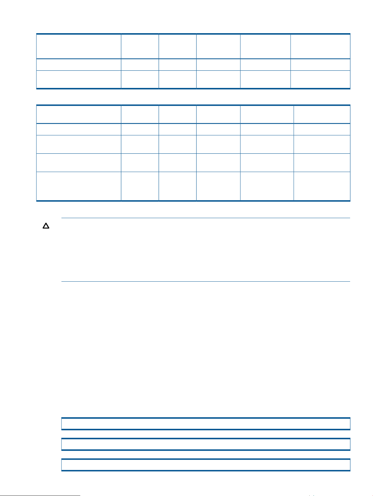
Table 12 Execution modes and options of the configuration setting command (line-by-line mode)
RemarksCommand
DefaultYesNoNoYesraidcom <action>
Check onlyNoNoNoYesraidcom <action> -checkmode
precheck
Context checkSyntax checkCommand syntax
Configuration
check
execution with no
error
Table 13 Execution modes and options of the configuration setting command (transaction mode)
RemarksCommand execution
DefaultExecutedNot executedExecutedExecutedraidcom -zt <script file>
With configuration
Check
Check onlyNot executedNot executedExecutedExecutedraidcom -zt < script file>
With configuration
Check
Check only
<work file>
-checkmode precheck
work file> -checkmode precheck
Context checkSyntax checkCommand syntax
Configuration
check
with no error
ExecutedExecutedExecutedExecutedraidcom -zt < script file> -load
Not executedExecutedExecutedExecutedraidcom -zt < script file> -load <
Detailed descriptions are provided in the following:
CAUTION:
• For raidcom -zt <script file>, specify an executable file name.
• Forraidcom -zt < script file> -load <work file>, either specify a full path name or store under
the c:\HORCM\etc folder.
• For raidcom -zt < script file> -checkmode precheck, either specify a full path name or store in
the current directory.
Context check
This check can be performed to ensure consistent content of the created script file. For example,
it can check if the script refers to an ldev_id that is already deleted in the preceding lines.
The script is executed only when no error is detected by the checking of whole script contents.
The following resources can be the target of the check:
• LDEV
• Port
• Host group
Checking the contents before executing the script helps reduce debugging after running the script.
How to check
The script is performed by specifying it as follows.
raidcom -zt <created script file name>
raidcom -zt <created script file name> -load <configuration file>
raidcom -zt <created script file name> -checkmode precheck
Command execution modes 57
Page 58

raidcom -zt <created script file name> -load<configuration file> -checkmode precheck
Details of check contents
Details of Context check is described below. Checking contents before issuing a script can reduce
load for the debug operation in a way of executing script.
LDEV check
The check is performed from the following perspective. Note that checking for the object information
that is related to the LDEV such as pool or device group, or an attribute of LDEV is not executed.
Check with the additional operation
It is checked to ensure that the same LDEV as the already existing LDEV is added. Attempting to
add the same LDEV generates an error.
If it is not clear whether the LDEV to be added exists or not (if the target LDEV information does
not exist in the configuration definition file), the error is not detected. Therefore, the script is executed
and the LDEV is added.
The command as the target of the check is shown below.
raidcom add ldev {-parity_grp_id <gno-sgno>| - external_grp_id <gno-sgno> | -pool {<pool ID#> | <pool naming>
| snap}} -ldev_id <ldev#> -capacity <size> [-emulation <emulation type>][-location <lba>][-mp_blade_id <mp#>]
Check with the attribute setting
It is checked whether the operation is performed for the existing LDEV or not. If the operation is
attempted to be performed for an LDEV that does not exist, an error is detected.
If it is not clear whether the LDEV as the target of the operation exists in the configuration definition
file or not (if the target LDEV information does not exist in the configuration definition file), the error
is not detected.
The command as the target of the check is shown below.
raidcom add lun -port <port> [host group name] {-ldev_id <ldev#> [-lun_id<lun#>] | -grp_opt <group option>
-device_grp_name <device group name> [<device name>]}
raidcom delete lun -port <port> [<host group name>] { -ldev_id <ldev#> | -grp_opt <group option> -device_grp_name
<device group name> [<device name>]}
raidcom add journal -journal_id <journal ID#> {-ldev_id <ldev#> …[-cnt <count>] | -grp_opt <group option>
-device_grp_name <device group name> [<device name>]} [-cnt <count>] [-mp_blade_id <mp#> | -timer_type <timer
type> ]
raidcom delete journal -journal_id <journal ID#> {-ldev_id <ldev#> | -grp_opt <group option> -device_grp_name
<device group name> [<device name>]}
raidcom add snap_pool {{-pool_id <pool ID#> [-pool_name <pool naming>] | -pool_name <pool naming>[-pool_id
<pool ID#>]} | -pool_id <pool ID#> -pool_name <pool naming>}} {-ldev_id <ldev#> …[-cnt<count>] | -grp_opt <group
option> -device_grp_name <device group name> [<device name>]}[-user_threshold <%> ]
raidcom add thp_pool {{-pool_id <pool ID#> [-pool_name <pool naming>] | -pool_name <pool naming>[-pool_id
<pool ID#>]} | -pool_id <pool ID#> -pool_name <pool naming>} {-ldev_id <ldev#> …[-cnt <count>] | -grp_opt <group
option> -device_grp_name <device group name> [<device name>]}[ -user_threshold <threshold_1> [<threshold_2>]
raidcom extend ldev {-ldev_id <ldev#> | -grp_opt <group option> -device_grp_name <device group name> [<device
name>]} -capacity <size>
raidcom check_ext_storage external_grp {-ldev_id <ldev#>| -grp_opt <group option> -device_grp_name <device
group name> [<device name>]}
raidcom add device_grp -device_grp_name <ldev group name> <device name> -ldev_id <ldev#>… [-cnt <count>]
raidcom delete device_grp -device_grp_name <device group name> -ldev_id<ldev#>… [-cnt <count>]
58 RAID Manager functions on P9500
Page 59

raidcom modify ldev -ldev_id <ldev#> {-status <status> | -device_name <ldev naming> | -mp_blade_id <mp#>}
raidcom initialize ldev {-ldev_id <ldev#> | -grp_opt <group option> -device_grp_name <device group name> [<device
name>]} -operation <type>
Check with the deletion operation
It is checked to ensure that the operation is not intended to be performed for the LDEV that is already
deleted. If it is, an error is detected.
If it is not clear whether the LDEV as the target of the operation exists in the configuration definition
file or not (if the target LDEV information does not exist in the configuration definition file), the error
is not detected.
The command as the target of the check is shown below.
raidcom delete ldev {-ldev_id <ldev#> | -grp_opt <group option> -device_grp_name <device group name> [<device
name>]}
The example of the script where the same LDEV is attempted to be added to the already created
LDEV and the execution result of the Context check is shown below.
• Example of the script
raidcom add ldev -parity_grp_id 01-01 -ldev_id 1 -capacity 100M
raidcom add ldev -parity_grp_id 01-01 -ldev_id 2 -capacity 100M
raidcom add ldev -parity_grp_id 01-01 -ldev_id 3 -capacity 100M
• Execution result
C:\HORCM\etc>raidcom get ldev -ldev_id 1 -cnt 65280 -store ldevconf_65 > ldevconf_65.txt
C:\HORCM\etc>raidcom -zt 3_defined_ldev.bat -load ldevconf_65.dat -checkmode precheck
C:\HORCM\etc>raidcom add ldev -parity_grp_id 01-01 -ldev_id 1 -capacity 100M
C:\HORCM\etc>raidcom add ldev -parity_grp_id 01-01 -ldev_id 2 -capacity 100M
C:\HORCM\etc>raidcom add ldev -parity_grp_id 01-01 -ldev_id 3 -capacity 100M
• Example of script (The text in bold indicates the part of incorrect configuration definition.)
raidcom add ldev -parity_grp_id 01-01 -ldev_id 1 -capacity 100M
raidcom add ldev -parity_grp_id 01-01 -ldev_id 2 -capacity 100M
raidcom add ldev -parity_grp_id 01-01 -ldev_id 3 -capacity 100M
raidcom add ldev -parity_grp_id 01-01 -ldev_id 1 -capacity 100M
raidcom add ldev -parity_grp_id 01-01 -ldev_id 2 -capacity 100M
raidcom add ldev -parity_grp_id 01-01 -ldev_id 3 -capacity 100M
for /l %%i in (1,1,3) do (
raidcom add ldev -parity_grp_id 01-01 -ldev_id %%i -capacity 100M
)
for /l %%i in (1,1,3) do (
raidcom add ldev -parity_grp_id 01-01 -ldev_id %%i -capacity 100M
)
Command execution modes 59
Page 60

• Execution result (The text in bold indicates the contents of the error accompanying the invalid
configuration definition in the script.)
C:\HORCM\etc>raidcom get ldev -ldev_id 1 -cnt 65280 -store ldevconf_65 > ldevconf_65.txt
C:\HORCM\etc>raidcom -zt 3_defined_ldev.bat -load ldevconf_65.dat -checkmode precheck
C:\HORCM\etc>raidcom add ldev -parity_grp_id 01-01 -ldev_id 1 -capacity 100M
C:\HORCM\etc>raidcom add ldev -parity_grp_id 01-01 -ldev_id 2 -capacity 100M
C:\HORCM\etc>raidcom add ldev -parity_grp_id 01-01 -ldev_id 3 -capacity 100M
C:\HORCM\etc>raidcom add ldev -parity_grp_id 01-01 -ldev_id 1 -capacity 100M
raidcom: LDEV(1) is already existing as status is [1] on UnitID# 0.
raidcom_#5: [EX_CTXCHK] Context Check error
C:\HORCM\etc>raidcom add ldev -parity_grp_id 01-01 -ldev_id 2 -capacity 100M
raidcom: LDEV(2) is already existing as status is [1] on UnitID# 0.
raidcom_#6: [EX_CTXCHK] Context Check error
C:\HORCM\etc>raidcom add ldev -parity_grp_id 01-01 -ldev_id 3 -capacity 100M
raidcom: LDEV(3) is already existing as status is [1] on UnitID# 0.
raidcom_#7: [EX_CTXCHK] Context Check error
The number in raidcom # of raidcom_#7: [EX_CTXCHK] Context Check error is the number of times
of performing the raidcom command by using <work file>. The number of times is incremented
each time the raidcom command is executed.
Port check
The check is performed from the following perspective. Note that checking for object information
related to the port, such as external volume group or RCU, or an attribute of port, is not executed.
Checking for attribute setting
It is checked whether the operation is performed for the existing port. If the port does not exist, an
error is detected.
If it is not clear whether the port as the target of the operation exists in the configuration definition
file or not (if the target port information does not exist in the configuration definition file), the error
is not detected.
The command as the target of the check is shown below.
raidcom modify port -port <port>{[-port_speed <value>] [-loop_id <value>][-topology <topology>] [-security_switch <
y|n >] | -port_attribute <port attribute>}
raidcom add external_grp -path_grp <path group#> -external_grp_id <gnosgno> -port <port> -external_wwn <wwn
strings> -lun_id <lun#> [-emulation <emulation type>]
raidcom add path -path_grp <path group#> -port <port> -external_wwn <wwn strings>
raidcom delete path -path_grp <path group#> -port <port> -external_wwn <wwn strings>
raidcom check_ext_storage path -path_grp <path group#> -port <port> -external_wwn <wwn strings>
raidcom disconnect path -path_grp <path group#> -port <port> -external_wwn <wwn strings>
raidcom add rcu cu_free <serial#> <id> <pid> mcu_port <port> rcu_port <port>
60 RAID Manager functions on P9500
Page 61

For example, if a path is attempted to be added to a port that does not exist, an error is detected.
An example of the script where the error is detected and the execution result of the actual Context
check are shown below.
• Example of script (The text in bold indicates the part of incorrect configuration definition.)
raidcom add path -path_grp 1 -port CL1-C -external_wwn 50060e80,06fc4180
raidcom add path -path_grp 1 -port CL1-D -external_wwn 50060e80,06fc4190
raidcom add path -path_grp 1 -port CL1-E -external_wwn 50060e80,06fc41a0
• Execution result (The text in bold indicates the contents of the error accompanying the invalid
configuration definition in the script.)
C:\HORCM\etc>raidcom get port -store portcnf_27.dat
PORT TYPE ATTR SPD LPID FAB CONN SSW SL Serial# WWN
CL1-A FIBRE TAR AUT EF N FCAL N 0 64539 06fc1b000000fc1b
CL1-B FIBRE TAR AUT EF N FCAL N 0 64539 50060e8006fc1b01
CL2-A FIBRE TAR AUT EF N FCAL N 0 64539 50060e8006fc1b10
CL2-B FIBRE TAR AUT EF N FCAL N 0 64539 50060e8006fc1b11
CL3-A FIBRE TAR AUT E8 N FCAL N 0 64539 50060e8006fc1b20
CL3-B FIBRE TAR AUT E0 N FCAL N 0 64539 50060e8006fc1b21
CL4-A FIBRE TAR AUT D6 N FCAL N 0 64539 50060e8006fc1b30
CL4-B FIBRE TAR AUT D2 N FCAL N 0 64539 50060e8006fc1b31
CL5-A FIBRE TAR AUT E4 N FCAL N 0 64539 50060e8006fc1b40
CL5-B FIBRE TAR AUT DC N FCAL N 0 64539 50060e8006fc1b41
CL6-A FIBRE TAR AUT D5 N FCAL N 0 64539 50060e8006fc1b50
CL6-B FIBRE TAR AUT D1 N FCAL N 0 64539 50060e8006fc1b51
CL7-A FIBRE ELUN AUT E2 N FCAL N 0 64539 50060e8006fc1b60
CL7-B FIBRE ELUN AUT DA N FCAL N 0 64539 50060e8006fc1b61
CL8-A FIBRE TAR AUT D4 N FCAL N 0 64539 50060e8006fc1b70
CL8-B FIBRE TAR AUT CE N FCAL N 0 64539 50060e8006fc1b71
C:\HORCM\etc>raidcom -zt 4_no_port.bat -load portcnf_27.dat -checkmode precheck
C:\HORCM\etc>raidcom add path -path_grp 1 -port CL1-C -external_wwn 50060e80,06fc4180
raidcom: PORT(2) does not exist as status is [2] on UnitID# 0.
raidcom_#2: [EX_CTXCHK] Context Check error
C:\HORCM\etc>raidcom add path -path_grp 1 -port CL1-D -external_wwn 50060e80,06fc4190
raidcom: PORT(3) does not exist as status is [2] on UnitID# 0.
raidcom_#3: [EX_CTXCHK] Context Check error
C:\HORCM\etc>raidcom add path -path_grp 1 -port CL1-E -external_wwn 50060e80,06fc41a0
raidcom: PORT(4) does not exist as status is [2] on UnitID# 0.
raidcom_#4: [EX_CTXCHK] Context Check error
Host group check
The check is performed from the following perspective. Note that checking for an attribute of host
group is not executed.
Check with the attribute setting
It is checked whether the operation is performed for the existing host group. If the host group does
not exist, an error is detected.
Command execution modes 61
Page 62

If it is not clear whether the target port or host group exists (if the target port or host group
information does not exist in the configuration definition file), the error is not detected.
The command as the target of the check is shown below.
raidcom modify host_grp -port <port> [<host group name>] -host_mode < host mode> [-host_mode_opt <host mode
option> … ]
raidcom add hba_wwn -port <port> [<host group name>] -hba_wwn <WWN strings>
raidcom delete hba_wwn -port <port> [<host group name>] -hba_wwn <WWN strings>
raidcom set hba_wwn -port <port> [<host group name>] -hba_wwn <WWN strings> -wwn_nickname <WWN
Nickname>
raidcom reset hba_wwn -port <port> [<host group name>] -hba_wwn <WWN strings>
raidcom add lun -port <port> [<host group name>] {-ldev_id <ldev#> [-lun_id<lun#>] | -grp_opt <group option>
-device_grp_name <device group name> [<device name>]}
raidcom delete lun -port <port> [<host group name>] {-lun_id <lun#> | -ldev_id <ldev#> | -grp_opt <group option>
-device_grp_name <device group name> [<device name>]}
Check with deletion operation
It is checked to ensure that the operation is not intended to be performed for the host group that
is already deleted. If the host group is already deleted, an error is detected.
If it is not clear whether the target port or host group exists or not (if the target port or host group
information does not exist in the configuration definition file), the error is not detected.
The command as the target of the check is shown below.
raidcom delete host_grp -port <port> [<host group name>]
For example, if attempting to delete a nonexistent host group, an error is detected. An example
of the script where the error is detected and the execution result of the actual context check are
shown below.
• Example of script (The text in bold indicates the part of incorrect configuration definition.)
raidcom delete host_grp -port CL1-A-0
raidcom delete host_grp -port CL1-A-1
raidcom delete host_grp -port CL1-A-2
• Execution result (The text in bold indicates the contents of the error accompanying the invalid
configuration definition in the script.)
C:\HORCM\etc>raidcom get host_grp –port CL1-A -store hostgrpcnf_27_cl1-a.dat
PORT GID GROUP_NAME Serial# HMD HMO_BITs
CL1-A 0 1A-G00 64539 LINUX/IRIX
C:\HORCM\etc>raidcom -zt 6_no_hstgrp.bat -load hostgrpcnf_27_cl1-a.dat
-checkmode precheck
C:\HORCM\etc>raidcom delete host_grp -port CL1-A-0
C:\HORCM\etc>raidcom delete host_grp -port CL1-A-1
raidcom: PORT-HGRP(0-1) does not exist as status is [2] on UnitID# 0.
raidcom_#3: [EX_CTXCHK] Context Check error
C:\HORCM\etc>raidcom delete host_grp -port CL1-A-2
raidcom: PORT-HGRP(0-2) does not exist as status is [2] on UnitID# 0.
62 RAID Manager functions on P9500
Page 63

raidcom_#4: [EX_CTXCHK] Context Check error
Configuration check
The contents of a script file can be checked whether the operation is performed for the existing
resource or not.
Before performing the configuration check, execute the following command, acquire the current
configuration information, and store it in the work file specified by the -store option.
Check the operation for LDEV
raidcom get ldev {-ldev_id <ldev#> … [-cnt <count>] | -grp_opt <group option> -device_grp_name <device group
name> [<device name>]} -store <work file>
Check the operation for Port
raidcom get port –port –store <work file>
Check the operation for Host group
raidcom get host_grp –port <port> –store <work file>
After acquiring the configuration information, execute the script by specifying the configuration
file.
raidcom -zt <created script file name> -load <work file>
LDEV group function
Overview
The DEV group function can create a group of multiple LDEVs (device group or copy group).
For RAID storage systems up to and including the XP24000/XP20000 Disk Array, RAID Manager
can be used to create a group of multiple LDEVs by defining copy groups, which are a group of
copy pairs. This is accomplished in both the primary and secondary configuration definition files
by defining the group names of the combined LDEVs (dev_name of HORCM_DEV or HORCM_LDEV).
To change copy group information, modify the primary and secondary configuration definition
files. For example, to change the LDEV configuration of copy group dbA (see following figure),
change the LDEV information in configuration definition files A and B.
LDEV group function 63
Page 64

Figure 29 LDEV grouping up to and including XP24000/XP20000 Disk Array
For P9500 RAID storage systems, RAID Manager can be used to create a group of multiple LDEVs
by defining device groups. This is accomplished by defining device groups in either the primary
or secondary configuration definition file, but not both. By defining a device group, LDEV information
can be changed or defined in one operation. It is not required to modify LDEV information in both
configuration definition files. For example, referencing LDEVs or creating pools can be executed
at the same time because the whole LDEV in the device group is subjected to the operation.
64 RAID Manager functions on P9500
Page 65
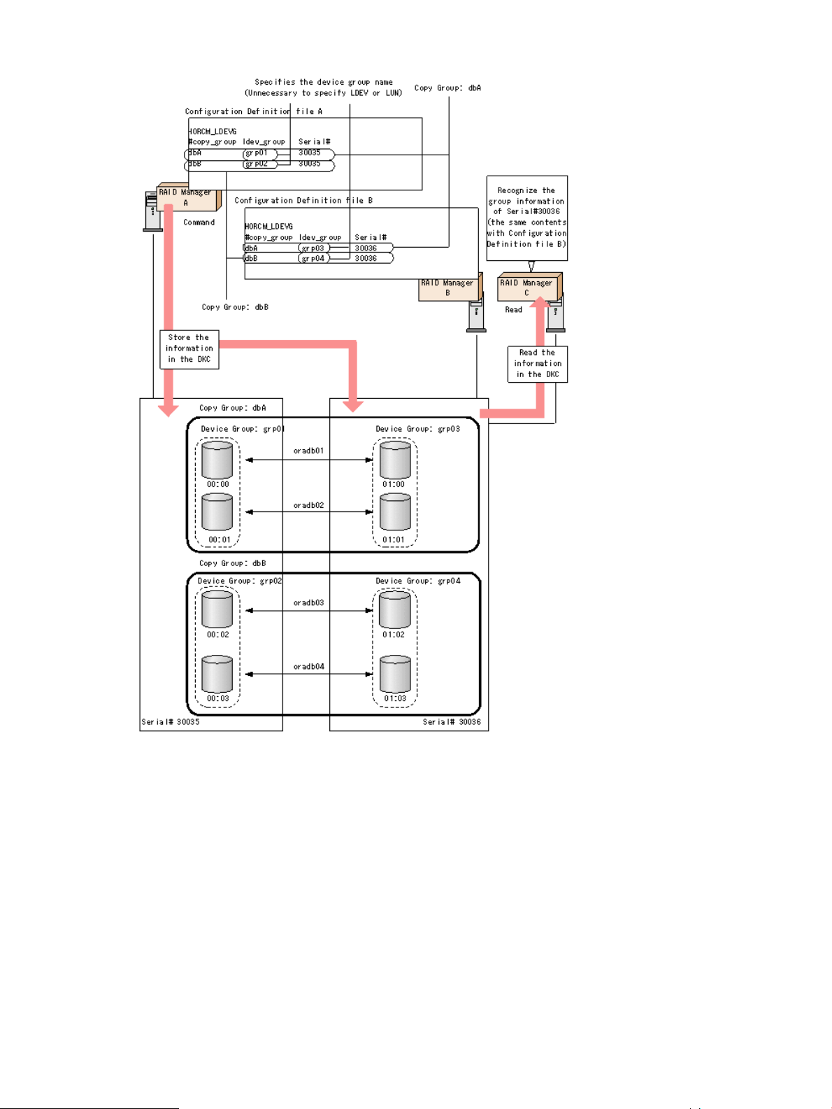
Figure 30 LDEV grouping from P9500 (device group and copy group)
However, for executing replication function commands in RAID Manager, two device groups must
be combined and defined as a copy group.
When defining a device group or copy group by a command, it can be used from multiple RAID
Manager instances because the group information is defined in the storage system.
Device group definition methods
To define a device group or copy group in the RAID Manager that supports P9500 or later, use
one or both of following methods.
• Execute a command
Creates a device group with the raidcom add device_grp, and specifies a device name and
device group name with which to define a copy group, and then executes the raidcom add
copy_grp command. Once the command is executed, the RAID Manager description of
LDEV group function 65
Page 66

HORCM_LDEV of the RAID Manager is defined within the storage system. It can be executed
by RAID Manager supporting P9500 or later.
• Define a configuration definition file
Defines HORCM_LDEV, HORCM_DEV, and HORCM_LDEVG of the configuration definition
files of the primary and secondary volumes. For definition details, see “Configuration definition
file” (page 24).
A device name is a name given to an LDEV in each device group.This is equivalent to the dev_name
definition of HORCM_DEV. A device name is not required, but it is convenient to use to specify
device group or device name instead of LDEV number. However, to create a pool or a journal,
specifying LDEV number is required.
The LDEVs that have the same device name are recognized as a pair in the primary and secondary
device group. Therefore, match the device name for the LDEV to be a pair. Also, the number of
LDEVs in the device group must be the same at the primary and secondary sides. Pairs are operated
in the ascending sequence of the LDEV numbers. If there is no corresponding device name of LDEV
in the device group to be paired, an error might occur on the pair operation.
Read operations and command device settings
When grouping LDEVs, if HORCM_LDEVG on the primary side and secondary side is not defined,
the read operation of RAID Manager is different depending on the command device settings. The
following table shows the details.
Table 14 Reading of command device setting and group information
Command device settingHORCM_LDEVG
User authenticationSecurity
setting
*1
: Read the entire group information in the storage system.
*2
: Read the information of device group and copy group from the contents of the configuration
Device group
definition
NoYesNo
NoNoYes
NoYesYes
---Defined
Reading of device group or copy
group information
Do not readNoNoNoNot defined
Do not readYes
*1
Read
Do not readYes
*1
Read
Do not readYes
*1
Read
Do not readYes
*2
Read
definition file regardless the setting of command device.
Device group function
A device group is created by specifying a device name and a device group name. Once a device
group is created, the device group name, the LDEV number, and the information if there is copy
group definition or not are stored in the storage system as a configuration information.
The maximum number of device groups is 1,024 in one storage system. The maximum 65,279
LDEVs can be placed under the device group. And one LDEV can be placed in multiple device
groups.
66 RAID Manager functions on P9500
Page 67

Notes when specifying a device name
• Multiple device names can be defined in one LDEV (Max: 1,024names).
• The length of a device name must be up to 32 characters.
• In the device group that does not become an element of copy a group, the same device name
can be used in the same device group.
• In the device group that becomes an element of a copy group, a device group name must be
unique in the device group. It is because a pair is created between LDEVs that have same
device names in respective primary and secondary volumes at the group operation of a
replication series command.
Notes when specifying a device group name
• The length of a device group name must be up to 32 characters.
• A device group name must be unique within the storage system. The device group name
cannot be duplicated in one storage system.
The contents of the following operations that can be executed for a device group are expressed
hereafter with its use cases.
1. Device group creation
2. LDEV addition to device group
3. LDEV deletion from device group
4. Device group deletion
Note: The following symbols are used in the use cases described hereafter.
LDEV group function 67
Page 68
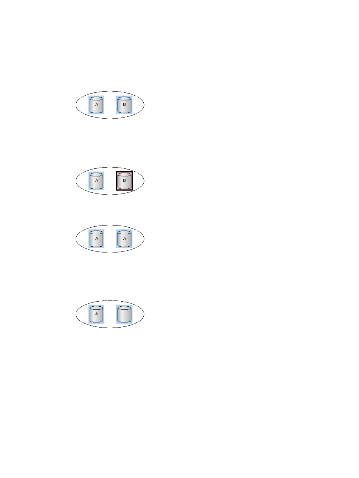
Device group creation
Creating a device group by specifying a subject of multiple LDEV IDs and device group names of
the device groups to be created.
• Use Cases
The following shows use cases that can be created a device group.
◦ Creating a device group configured of simplex volumes with different LDEV names.
In this example, the device group can be created.
◦ Creating a device group configured of a single volume and a paired volume with different
LDEV names.
◦ Creating a device group configured of the same LDEV names.
As there are use cases other than duplication, (the same LDEV name is) permitted (e.g.
Map LUN and others).
◦ Creating a device group including an LDEV without an LDEV name in the group.
As there are use cases other than duplication, (the absence of an LDEV name is) permitted
(e.g. Map LUN and others).
LDEV addition to device group
Adding an LDEV to the device group by specifying a created device group name and the LDEV
ID of the LDEV to be added.
68 RAID Manager functions on P9500
Page 69
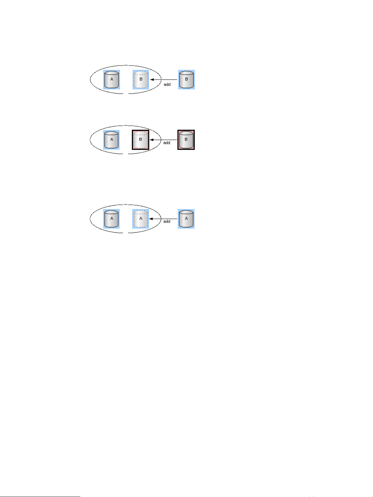
• Use Cases
The following shows use cases that can be added an LDEV to a device group.
◦ Adding an LDEV (simplex volume) with a different device name to a device group.
◦ Adding an LDEV (paired volume) with a different device name to a device group.
◦ Adding an LDEV to a device group already including the same device name.
The device name can be duplicated in the case of not creating the copy group by
specifying a device group.
LDEV deletion from device group
Deleting an LDEV from the device group by specifying a created device group name and an LDEV
ID of the LDEV to be deleted.
LDEV group function 69
Page 70

LDEV can be deleted from the device group associating a copy group. The pair status does not
change even if the LDEV is deleted from the device group.
• Use Cases
The following shows use cases that can be deleted an LDEV from a device group.
◦ Deleting an LDEV (simplex volume) not associated with a copy group from a device group.
• Deleting an LDEV (paired volume) not associated with a copy group from a device group.
• Deleting an LDEV (simplex volume) associated with a copy group from a device group.
• Deleting an LDEV (paired volume) associated with a copy group from a device group.
Device group deletion
Deleting an LDEV that configuring a device group by specifying a created device group name and
an LDEV ID of the LDEV to be deleted. If all the LDEVs configuring the device group are deleted
70 RAID Manager functions on P9500
Page 71
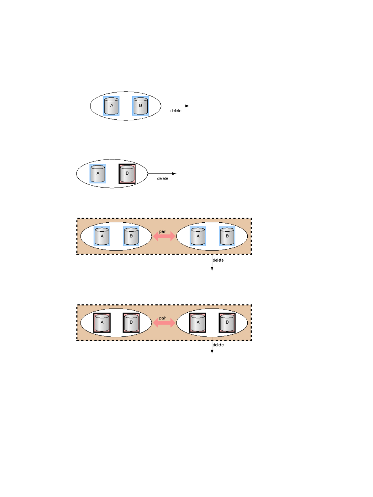
from the device, the relevant device group is deleted. And, even if a device group is deleted, the
pair status of the pair in the device group does not change.
• Use Cases
The following shows use cases that can be deleted an LDEV from a device group.
◦ Deleting a device group configured of simplex volumes and not associated with a copy
group.
• Deleting a device group configured of a simplex volume and a paired volume and not
associated with a copy group.
• Deleting a device group configured of simplex volumes and associated with a copy group.
• Deleting a device group configured of paired volumes and associated with a copy group.
Copy group function
Defining a copy group by specifying two device groups: one device group from primary side and
one device group from secondary side, whether they are inside or outside the storage system. A
copy group cannot be defined by specifying more than one device group from just one side of
primary or secondary.
When a copy group is created, which device group is primary and which is secondary cannot be
specified. Therefore, it is specified at the time of actual pair creation. As configuration information,
a copy group name, a device group name (primary and secondary), and an MU# are maintained
in the storage system.
The notes when operating copy groups are shown below.
LDEV group function 71
Page 72
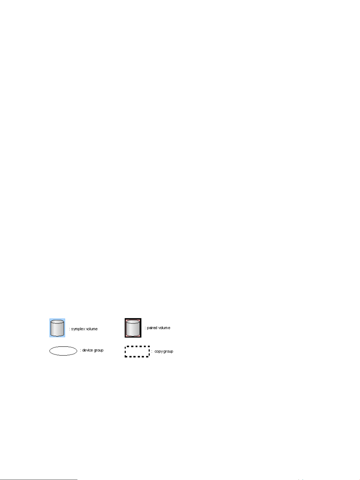
When creating a copy group
• In case of creating a copy group by executing a command, a copy group cannot be created
through direct specification of multiple LDEVs. Create a copy group by specifying a device
group.
• In one device group associated as a copy group, the same device name cannot be defined.
• Copy groups with the same name cannot be defined within the same storage system.
• One device group cannot be defined to multiple copy groups.
• The number of copy groups must be up to 16384 per storage system.
• At the time of consistency group creation (pair creation) and consistency group deletion (pair
deletion), the collaboration with the group operations (device group creation/deletion, copy
group creation/deletion) is not performed.
When deleting a copy group
• If a copy group is deleted, the association of two device groups is deleted. However, the
actual pair status, the consistency group ID and others are not changed (not affected). Even
if the pair status in the copy group is not single and the copy group is deleted, the copy group
deletion processing is performed.
• If an LDEV is deleted from a device group associated as a copy group, the relevant LDEVs
are deleted from all the associated copy groups.
• A copy group defines the relationship of device groups. Therefore, it is not possible to specify
an LDEV and remove it from the copy group.
• Regardless of the pair status (copy status), it is possible to exclude LDEVs from device groups
associated as a copy group.
The contents of the following operations that can be executed for a copy group are expressed
hereafter with its use cases.
1. Copy group creation
2. LDEV addition to copy group
3. LDEV deletion from copy group
4. Copy group deletion
5. Pair operation by specifying a copy group
Note: The following symbols are used in the use cases described hereafter.
72 RAID Manager functions on P9500
Page 73
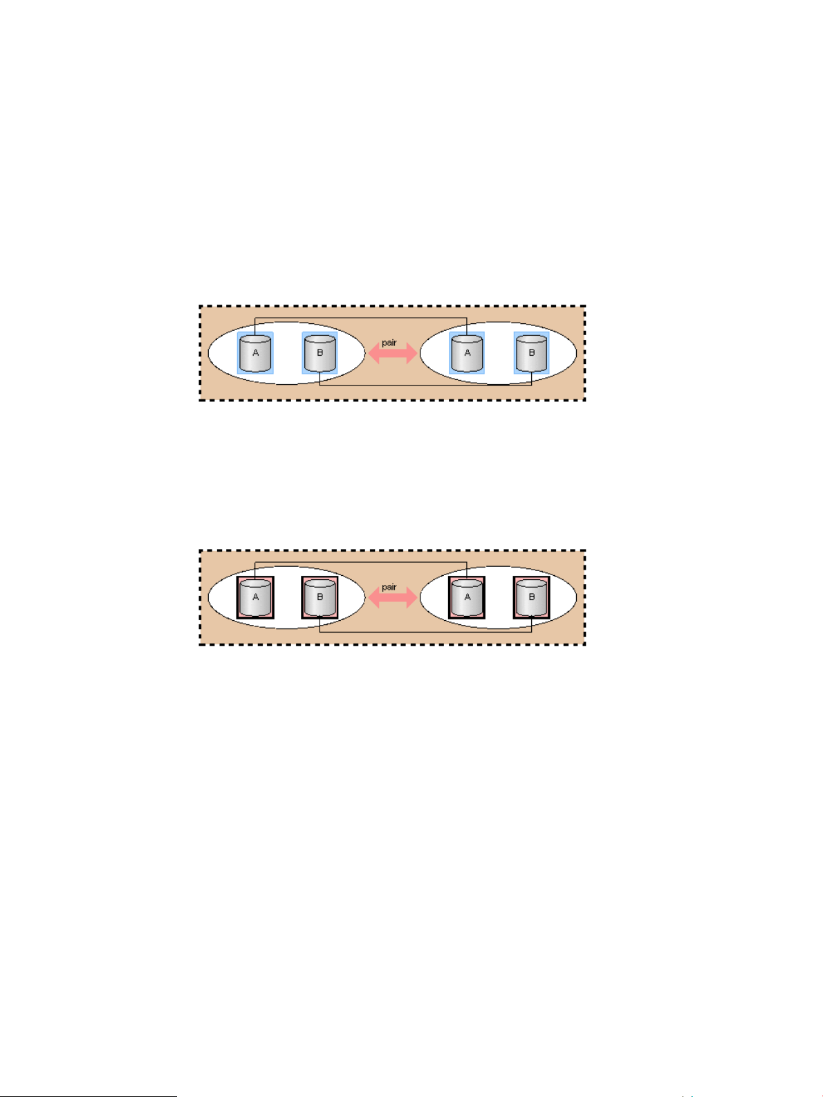
Copy group creation
Specifying two device groups and creating a copy group. The same device name must not be
defined for any LDEVs in a specified device group. A copy group can be created whether the
LDEV in the device group is paired status or not.
• Use cases
The following shows use cases that can be created a copy group.
◦ Creating a copy group in cases where two device groups are configured of simplex
volumes and the device names and the LDEV numbers in the respective device groups
are the same.
In the following example, when a copy group is created, the LDEVs within the device
names of A to A and B to B become a subject of pair operation.
◦ Creating a copy group in cases where two device groups are configured of paired
volumes and the device names and the LDEV numbers in the respective device groups
are the same.
In the following example, although pairs have been created on the device names of A
to A and B to B, a copy group can be created.
LDEV addition to a copy group
Adding an LDEV to a device group by specifying a device group name forming a copy group. It
is not possible to add LDEVs directly to the copy group.
LDEV group function 73
Page 74

With the same device name, the operation for the device group associated with a copy group
cannot be performed.
• Use cases
The following shows use cases that can be added an LDEV to the device group associating a
copy group.
◦ Adding an LDEV with a different device name (simplex volume) to a device group forming
a copy group.
◦ Adding an LDEV with a different device name (paired volume) to a device group forming
a copy group.
LDEV deletion from copy group
Deleting an LDEV from a device group forming a copy group. It can be deleted both the simplex
volume or paired volume LDEVs.
74 RAID Manager functions on P9500
Page 75

It is not possible to delete LDEVs directly from the copy group.
• Use cases
The following shows use cases that can be deleted LDEVs from the device group forming a
copy group.
◦ Deleting an LDEV (simplex volume) from a device group forming a copy group.
◦ Deleting an LDEV (paired volume) from a device group forming a copy group.
Copy group deletion
Deleting a copy group by specifying a defined copy group.
LDEV group function 75
Page 76

• Use cases
A copy group can be deleted even if it is configured of simplex volumes or paired volumes.
The following shows use cases that can be deleted a copy group.
◦ Deleting a copy group configured of simplex volumes.
◦ Deleting a copy group configured of paired volumes.
Pair operation by specifying a copy group
Specifying a copy group and creating a pair. Pairs are created for which the same device names
of LDEV defined in respective device groups of the LDEVs. Therefore, it is required to give a same
device name for the item to be operated as a pair.
If a consistency group attribute is valid and no consistency group ID is specified, automatically
assign a consistency group ID (1 copy group=1 consistency group). If the automatic consistency
group assignment is specified and the other pairs in a copy group already have consistency group
IDs, assign the same consistency group ID.
76 RAID Manager functions on P9500
Page 77

If there is no target LDEV to be a pair in the copy group, the process is terminated by detecting
an error.
LDEV group function 77
Page 78

• Use cases
As an example of pair operation, the following shows use cases that can be created a pair
by specifying a copy group.
◦ Creating a pair in cases where the device names and the numbers of LDEVs in two device
groups in a copy group configured of simplex volumes are the same.
In the following example, pairs are created with LDEVs that have the same device name,
A to A and B to B.
◦ Creating a pair in cases where the device names and the numbers of LDEVs in two device
groups in a copy group configured of simplex volumes and paired volumes are the same.
In the following example, a pair is created with LDEVs for the device name A. And no
operation is performed for the volumes of device name B that are already formed into
copy pairs.
◦ Creating a pair in cases where different device names exist in two device groups in a
copy group configured of simplex volumes.
In the following example, a pair for device name A can be created, but not for device
name B and C because they have different names.
◦ Creating a pair in cases where the device names in two device groups in a copy group
configured of simplex volumes and paired volumes are different.
In the following example, a pair for device name A to A can be created. For the device
name B and C, although it does not change the paired status, but an error occurs because
they have different device names.
78 RAID Manager functions on P9500
Page 79

◦ Creating a pair in cases where the numbers of LDEVs in two device groups in a copy
group configured of simplex volumes are different.
In the following example, pairs are created for the device name A to A and B to B.
Pair operations with volumes for mainframe
For the P9500 storage system, you can create a pair with LDEVs for mainframe by using RAID
Manager. Because there are some unusable functions, see the HP P9000 Continuous Access
Synchronous for Mainframe Systems User Guide, HP P9000 Continuous Access Journal for
Mainframe Systems User Guide, and HP P9000 Business Copy Mainframe Systems User Guide
for more detailed information.
Using dummy LU
To use LDEVs for mainframe, you must define pseudo LUs (dummy LUs). The dummy LUs are
unconditionally defined when the emulation types of LDEVs are for mainframe systems. Since the
dummy LUs are used by only RAID Manager, other user interfaces, for example Remote Web
Console and host servers, do not display the dummy LUs. You cannot define host modes for dummy
LUs. Two dummy LUs are assigned to an LDEV for mainframe. The port IDs of mainframe PCBs are
assigned as the port IDs for dummy LUs.
The port number of dummy LUs are derived from the following formula.
Port#:Installed Port#(*1) (LDEV# / 0x4000)x32
Installed Port#(*1) (LDEV# / 0x4000)x32+1
*1: The minimum port number of installed ports for mainframe.
TID: (LDEV# & 03xFCO)/64
LU-M: (LDEV# &0x3F)
The mainframe volume pair can be executed just like the open volume when specifying LDEV# of
the mainframe at the HORCM_LDEV in a configuration definition file.
If you specify existing mainframe pairs, verify their MU # by using the raidscan command.
Pair operations with volumes for mainframe 79
Page 80

Displayed pair statuses
Pair statuses of mainframe LDEVs are displayed in a same way as those of open LDEVs. However,
access permissions to mainframe P-VOLs or S-VOLs are different from those of open volumes. The
pair statuses and access permissions to mainframe LDEVs are shown below. For more information
about displayed pair statuses of open LDEVs, see (page 129).
Table 15 Pair statuses of Continuous Access Synchronous/Continuous Access Synchronous Z
#
Console
4
suspended
split)
5
suspended
error)
Notes:
1. When the option mode 20 is on, this is a read only volume.
2. PDUB (inconsistency in LUSE status) does not exist in the mainframe system.
3. SSWS does not exist in the mainframe system.
Pair statuses in RAID ManagerPair statuses in Remote Web
MainframeOpenMainframeOpen
SMPLSMPLSimplexSMPL1
COPYCOPYPendingCOPY2
PAIRPAIRDuplexPAIR3
PSUSPSUSSuspendedPSUS (pair
PSUEPSUESuspendedPSUE (pair
2
PDUB-PDUB6
SSWS-SSWS7
-
3
-
Access to
mainframe
P-VOL
Read / Write
enabled
enabled
enabled
Read / Write
enabled
Read / Write
enabled
enabled
enabled
mainframe
S-VOL
enabled
1
1
-Read / Write
-Read / Write
NotesAccess to
not in pairRead / Write
in copyingRejectRead / Write
pairRejectRead / Write
suspendReject
suspend by failureReject
inconsistency in
LUSE status
ESAM only/
horctakeover only
Table 16 Pair statuses of Continuous Access Journal/Continuous Access Journal Z
#
Console
4
suspended
split)
5
suspended
error)
80 RAID Manager functions on P9500
Pair statuses in RAID ManagerPair statuses in Remote Web
MainframeOpenMainframeOpen
SMPLSMPLSimplexSMPL1
COPYCOPYPendingCOPY2
PAIRPAIRDuplexPAIR3
PSUSPSUSSuspendPSUS (pair
PSUEPSUESuspendPSUE (pair
PAIRPAIRSuspendingSuspending6
Access to
mainframe
P-VOL
Read / Write
enabled
enabled
enabled
enabled
enabled
enabled
mainframe
S-VOL
enabled
NotesAccess to
not in pairRead / Write
in copyingRejectRead / Write
pairRejectRead / Write
suspendReject*Read / Write
suspendReject*Read / Write
pairRejectRead / Write
Page 81

Table 16 Pair statuses of Continuous Access Journal/Continuous Access Journal Z (continued)
#
Console
*When the system option 20 is on, this is a read only volume.
Pair statuses in RAID ManagerPair statuses in Remote Web
MainframeOpenMainframeOpen
PAIR / COPYPAIR / COPYDeletingDeleting7
PSUSPSUSHoldHOLD8
PSUSPSUSHoldingHOLDING9
PSUEPSUEHldePSUS (HLDE)10
PFULPFULSuspendPFUL11
PFUSPFUSSuspendPFUS12
SSWSSSWSSuspendSSWS13
Table 17 Pair statuses of Business Copy/Business Copy Z
Access to
mainframe
P-VOL
enabled
enabled
enabled
enabled
enabled
enabled
enabled
NotesAccess to
mainframe
S-VOL
pair / in copyRejectRead / Write
suspendReject*Read / Write
suspend-Read / Write
suspendRejectRead / Write
suspendRejectRead / Write
suspendRejectRead / Write
suspendRejectRead / Write
#
6
7
Console
suspended
split)
suspended
error)
Pair statuses in RAID ManagerPair statuses in Remote Web
MainframeOpenMainframeOpen
SMPLSMPLSimplexSMPL1
COPYCOPYPendingCOPY(PD)2
PAIRPAIRDuplexPAIR3
COPYCOPYSP-PendCOPY (SP)4
PSUSPSUSV-splitPSUS (SP)5
PSUSPSUSSplitPSUS (pair
PSUEPSUESuspendPSUE (pair
Access to
mainframe
P-VOL
Read / Write
enabled
enabled
enabled
enabled
Read / Write
enabled
Read / Write
enabled
enabled
mainframe
S-VOL
enabled
RejectRead / Write
Read / Write
enabled
enabled
NotesAccess to
simplexRead / Write
in copyingRejectRead / Write
pairRejectRead / Write
suspend (in
COPY(SP)
COPY-COPY)
suspend (in Quick
Split PSUS-COPY)
suspendRead / Write
suspend by failureRejectRead / Write
in resynchronizingRejectRejectCOPYCOPYResyncCOPY (RS)8
Multi-platform volumes
Differences in Continuous Access Synchronous, Continuous Access Journal, and Business Copy
multi-platform volumes performance are shown below.
RCPYRCPYResync-RCOPY (RS-R)9
enabled
Pair operations with volumes for mainframe 81
in restoringRejectRead / Write
Page 82

Table 18 Comparing multi-platform volumes performance
LU path information
reported to RAID
Manager
Actual LU path
information is
reported.
Dummy LU number is
reported.
2
LU path definition#
LU path is defined.1
LU path is not
defined.
Differences in replication commands
Differences between open volumes and mainframe volumes in replication commands are shown
below. For details on the differences, see the manual for each program product.
Table 19 Differences in replication commands
DescriptionOptionCommand#
-c <size>paircreate*1
Specifies track
size when
copying.
Business Copy
performance
Business Copy Z
performance
Business Copy Z
performance
Performance in
open system
Continuous
Access
Synchronous:
1 to 15 tracks. There is no difference
Continuous Access
Synchronous
performance
Commands are
rejected.
Commands are
rejected.
mainframe
system
Continuous
Access
Synchronous Z:
3 or 15 tracksYou can specify
When you
specify the
number 1 to 3,
the copy speed is
3 tracks.
When you
specify the
number 4 to 15,
the copy speed is
15 tracks.
Continuous Access
Journal performance
Commands are
rejected.
Commands are
rejected.
NotesPerformance in
This option is not supported
in Continuous Access
Journal and Continuous
Access Journal Z.
between Business Copy
and Business Copy Z.
2
pairsplit3
-m grp
[CTGID]
-r
-rw
• If CTGID is not
specified,
CTGID is
automatically
assigned and
a pair is
registered to
the CT group.
• If CTGID is
specified, a
pair is
registered to
the CTGID in
use.
Specifies access
mode to S-VOL
after splitting a
pair.
You can specify
this option.
-r: Read only
-rw: Read /
Write enabled
You can specify
this option.
The volume
cannot be read
regardless of
specified options.
Business Copy pairs and
Business Copy Z pairs
cannot be registered to the
same CTG ID.
If both Business Copy pairs
and Business Copy Z pairs
are registered to one
group, the command ends
abnormally.
This option is only for
Continuous Access
Synchronous, Continuous
Access Synchronous Z,
Continuous Access Journal,
and Continuous Access
Journal Z.
82 RAID Manager functions on P9500
Page 83

Table 19 Differences in replication commands (continued)
DescriptionOptionCommand#
*If the capacity of the secondary volume (S-VOL) is larger than that of the primary volume (P-VOL), you cannot create
a pair with RAID Manager. To create a Continuous Access Synchronous Z pair with volumes that differ in capacity,
use Business Continuity Manager or Remote Web Console.
Notes:
• A primary volume may be called an source volume or a main volume in a mainframe system.
• A secondary volume may be called a target volume or a remote volume in a mainframe system.
Performance in
open system
mainframe
system
NotesPerformance in
You cannot specify this
option in Business Copy
and Business Copy Z.
Pair operations with volumes for mainframe 83
Page 84

4 Starting up RAID Manager
After you have installed the RAID Manager software, set the command device, created the
configuration definition file(s), and (for OpenVMS only) followed the porting requirements and
restrictions, you can begin using the RAID Manager software. One or two instances of RAID
Manager can be used simultaneously in the UNIX, Windows, and OpenVMS operating system
environments.
Starting up on UNIX systems
One instance
To start up one instance of RAID Manager on a UNIX system:
1. Modify /etc/services to register the port name/number (service) of each configuration definition
file. The port name/number must be different for each RAID Manager instance.
horcm0 xxxxx/udp
xxxxx = the port name/number for horcm0.conf
horcm1 yyyyy/udp
yyyyy = the port name/number for horcm1.conf
2. If you want HORCM to start automatically each time the system starts up, add
/etc/horcmstart.sh 0 1 to the system automatic startup file (e.g., /sbin/rc).
3. Execute the horcmstart.sh script manually to start the RAID Manager instances: # horcmstart.sh
0 1
4. Set an instance number to the environment that executes a command:
For B shell: # HORCMINST=X
X = instance number = 0 or 1 # export HORCMINST
For C shell: # setenv HORCMINST X
5. Set the log directory (HORCC_LOG) in the command execution environment as needed.
6. If you want to perform Continuous Access Synchronous operations, do not set the HORCC_MRCF
environment variable. If you want to perform Business Copy operations, set the HORCC_MRCF
environment variable for the HORCM execution environment.
For B shell:
# HORCC_MRCF=1 # export HORCC_MRCF
For C shell:
# setenv HORCC_MRCF 1 # pairdisplay -g xxxx xxxx = group name
Two instances
To start up two instances of RAID Manager on a UNIX system:
1. Modify /etc/services to register the port name/number (service) of each configuration definition
file. The port name/number must be different for each RAID Manager instance.
horcm0 xxxxx/udp
xxxxx = the port name/number for horcm0.conf
horcm1 yyyyy/udp
yyyyy = the port name/number for horcm1.conf
2. If you want HORCM to start automatically each time the system starts up, add
/etc/horcmstart.sh 0 1 to the system automatic startup file (e.g., /sbin/rc).
84 Starting up RAID Manager
Page 85

3. Execute the horcmstart.sh script manually to start the RAID Manager instances: # horcmstart.sh
0 1
4. Set an instance number to the environment that executes a command:
For B shell:
# HORCMINST=X
X = instance number = 0 or 1 # export HORCMINST
For C shell:
# setenv HORCMINST X
5. Set the log directory (HORCC_LOG) in the command execution environment as needed.
6. If you want to perform Continuous Access Synchronous operations, do not set the HORCC_MRCF
environment variable. If you want to perform Business Copy operations, set the HORCC_MRCF
environment variable for the HORCM execution environment.
For B shell:
# HORCC_MRCF=1 # export HORCC_MRCF
For C shell:
# setenv HORCC_MRCF 1 # pairdisplay -g xxxx
xxxx = group name
Starting up on Windows systems
One instance
To start up one instance of RAID Manager on a Windows system:
1. Modify \WINNT\system32\drivers\etc\services to register the port name/number (service)
of the configuration definition file. Make the port name/number the same on all servers:
horcm xxxxx/udp xxxxx = the port name/number of horcm.conf
2. If you want HORCM to start automatically each time the system starts up, add
\HORCM\etc\horcmstart to the system automatic startup file (e.g., \autoexec.bat).
3. Execute the horcmstart script manually to start RAID Manager: D:\HORCM\etc> horcmstart
4. Set the log directory (HORCC_LOG) in the command execution environment as needed.
5. If you want to perform Continuous Access Synchronous operations, do not set the HORCC_MRCF
environment variable. If you want to perform Business Copy operations, set the HORCC_MRCF
environment variable for the HORCM execution environment:
D:\HORCM\etc> set HORCC_MRCF=1 D:\HORCM\etc> pairdisplay -g xxxx
xxxx = group name
Two instances
To start up two instances of RAID Manager on a Windows system:
1. Modify \WINNT\system32\drivers\etc\services to register the port name/number (service)
of the configuration definition files. Make sure that the port name/number is different for each
instance:
horcm0 xxxxx/udp
xxxxx = the port name/number of horcm0.conf
horcm1 xxxxx/udp
xxxxx = the port name/number of horcm1.conf
2. If you want HORCM to start automatically each time the system starts up, add
\HORCM\etc\horcmstart 0 1 to the system automatic startup file (e.g., \autoexec.bat).
Starting up on Windows systems 85
Page 86

3. Execute the horcmstart script manually to start RAID Manager: D:\HORCM\etc> horcmstart 0
1
4. Set an instance number to the environment that executes a command: D:\HORCM\etc> set
HORCMINST=X
X = instance number = 0 or 1
5. Set the log directory (HORCC_LOG) in the command execution environment as needed.
6. If you want to perform Continuous Access Synchronous operations, do not set the HORCC_MRCF
environment variable. If you want to perform Business Copy operations, set the HORCC_MRCF
environment variable for the HORCM execution environment:
D:\HORCM\etc> set HORCC_MRCF=1 D:\HORCM\etc> pairdisplay -g xxxx
xxxx = group name
Starting up on OpenVMS systems
One instance
To start up one instance of RAID Manager on an OpenVMS system:
1. Create the configuration definition file.
For a new installation, the configuration definition sample file is supplied
(SYS$POSIX_ROOT:[HORCM.etc]horcm.conf). Make a copy of the file: $ COPY
SYS$POSIX_ROOT:[HORCM.etc]horcm.conf SYS$POSIX_ROOT:[etc]
Edit this file according to the system configuration using a text editor (e.g., eve).
Register the port name (service) of the configuration definition file in
"SYS$SYSROOT:[000000.TCPIP$ETC]SERVICES.DAT ".
[horcm xxxxx/udp. where "xxxxx" denotes a port number]
Use the same port number in all servers. The port number can be directly specified without
registering it in "SYS$SYSROOT:[000000.TCPIP$ETC]SERVICES.DAT".
2. Manually execute the HORCM startup command.
$ spawn /nowait /process=horcm horcmstart
NOTE: The subprocess(HORCM) created by SPAWN is terminated when the terminal is in
the LOGOFF state or the session is terminated. If you want independence Process to the terminal
LOGOFF, then use “RUN /DETACHED” command.
3. Confirm the configuration.
Set the log directory (HORCC_LOG) in the command execution environment as required.
NOTE: If the log directory under SYS$POSIX_ROOT is shared with other nodes, the log
directory of Horc Manager must be set for each node. The log directory of Horc Manager
can be changed by setting the parameter of horcmstart. See the HP StorageWorks P9000
RAID Manager Reference Guide for information on horcmstart parameters.
When the command issued is for HOMRCF, set the environment variable (HORCC_MRCF).
$ HORCC_MRCF:=1 $ pairdisplay -g xxxxWhere “xxxx” denotes a group name.
NOTE: If a system configuration change or a RAID configuration change causes this file to
change, (e.g., cache size change or microcode change), these changes will not take effect until
you stop HORCM (horcmshutdown) and restart HORCM (horcmstart). Use the “-c” option of the
pairdisplay command to verify that there are no configuration errors.
86 Starting up RAID Manager
Page 87

Two instances
To start up two instances of RAID Manager on an OpenVMS system:
1. Create the configuration definition files.
For a new installation, the configuration definition sample file is supplied
(SYS$POSIX_ROOT:[HORCM.etc]horcm.conf). Copy the file twice, once for each instance.
$ COPY SYS$POSIX_ROOT:[HORCM.etc]horcm.conf SYS$POSIX_ROOT:[etc] horcm0.conf
$ COPY SYS$POSIX_ROOT:[HORCM.etc]horcm.conf SYS$POSIX_ROOT:[etc] horcm1.conf
Edit these two files according to the system configuration using a text editor (e.g., eve).
Register the port name (service) of the configuration definition file in
“SYS$SYSROOT:[000000.TCPIP$ETC]SERVICES.DAT”.
horcm0 xxxxx/udp. Where "xxxxx" denotes a port number. horcm1 yyyyy/udp. Where
"xxxxx" denotes a port number.
Each instance should have a unique port number.
The port number can be directly specified without registering it in
“SYS$SYSROOT:[000000.TCPIP$ETC]SERVICES.DAT”.
2. Execute the HORCM startup command.
$ spawn /nowait /process=horcm0 horcmstart 0 $ spawn /nowait /process=horcm1 horcmstart
1
NOTE: The subprocess(HORCM) created by SPAWN is terminated when the terminal is
LOGOFF or the session is terminated. If you want independence Process to the terminal
LOGOFF, then use “RUN /DETACHED” command.
3. Set the HORCM instance numbers in the environment in which the command is to be executed:
$ HORCMINST:=X where “X” denotes an instance number (0 or 1)
4. Confirm the configuration using a RAID Manager command.
Set the log directory (HORCC_LOG) in the command execution environment as required.
NOTE: If the log directory under SYS$POSIX_ROOT is shared with other nodes, the log
directory of Horc Manager must be set for each node. The log directory of Horc Manager
can be changed by setting the parameter of horcmstart. See the HP StorageWorks P9000
RAID Manager Reference Guide for information on horcmstart parameters.
When the command issued is for HOMRCF, set the environment variable (HORCC_MRCF). $
HORCC_MRCF:=1 $ pairdisplay -g xxxx xxxx denotes a group name.
NOTE: If a system configuration change or a RAID configuration change causes this file to
change (e.g., cache size change, microcode change), these changes will not take effect until you
stop HORCM (horcmshutdown 0 1) and restart HORCM (horcmstart 0 and horcmstart 1). Use the
“-c” option to pairdisplay command to verify that there are no configuration errors.
Starting RAID Manager as a service (Windows systems)
Usually, RAID Manager (HORCM) is started by executing the startup script from the Windows
services. However, in the VSS environment, there is no interface to automatically start RAID Manager.
As a result, RAID Manager provides the following svcexe.exe command and a sample script
(HORCM0_run.txt) file so that RAID Manager can be started automatically from the services:
Starting RAID Manager as a service (Windows systems) 87
Page 88

C:\HORCM\tool\>svcexe
• Usage for adding [HORCM_START_SVC]: svcexe /A=command_path
◦ for deleting [HORCM_START_SVC]: svcexe /D
◦ for specifying a service: svcexe /S=service_name
◦ for dependent services: svcexe /C=service_name,service_name
This command example uses HORCM0 for registering the service name for HORCM instance#0:
• Example for adding [HORCM0]: svcexe /S=HORCM0 “/A=C:\HORCM\tool\svcexe.exe”
◦ for deleting [HORCM0]: svcexe /S=HORCM0 /D
◦ for starting [HORCM0]:
1. Make a C:\HORCM\tool\HORCM0_run.txt file.
2. Set a user account to this service.
3. Confirm to start by horcmstart 0.
4. Confirm to stop by horcmshutdown 0.
5. Start from a service by net start HORCM0.
Performing Additional Configuration Tasks
1. Registering the HORCM instance as a service. The system administrator must add the HORCM
instance using the following command:
C:\HORCM\tool\>svcexe /S=HORCM0 “/A=C:\HORCM\tool\svcexe.exe”
2. Customizing a sample script file. The system administrator must customize the sample script
file (HORCM0_run.txt) according to the HORCM instance. For details, see the descriptions in
the HORCM0_run.txt file.
3. Setting the user account. The system administrator must set the user account for the RAID
Manager administrator as needed.
When using the GUI, use “Administrative Tools - Services - Select HORCM0 - Logon”.
When using the CUI, use “sc config” command as follows:
C:\HORCM\tool\>sc config HORCM0 obj= AccountName password= password
If the system administrator uses default account (LocalSystem), add “HORCM_EVERYCLI=1”:
# **** For INSTANCE# X, change to HORCMINST=X as needed ****
START:
set HORCM_EVERYCLI=1
set HORCMINST=0
set HORCC_LOG=STDERROUT
C:\HORCM\etc\horcmstart.exe
exit 0
4. Starting the HORCM instance from the service. After you have confirmed starting and stopping
using “horcmstart 0” and “horcmshutdown 0”, you must verify that HORCM0 starts from the
service and that HORCM0 started automatically from REBOOT, using the following command:
C:\HORCM\tool\>net start HORCM0
5. Stopping HORCM instance as a service. Instead of using the “horcmshutdown 0” command,
you must use the following command to stop HORCM0:
C:\HORCM\tool\>net stop HORCM0
(By using the “horcmshutdown 0” command, the script written into HORCM0_run.txt will
automatically restart HORCM0).
88 Starting up RAID Manager
Page 89

5 Provisioning operations with RAID Manager
Provisioning operations can be performed using RAID Manager.
About provisioning operations
Provisioning operations can be performed using RAID Manager.
For details about the provisioning, see HP StorageWorks P9000 Provisioning for Open Systems
User Guide.
NOTE: The operation of refreshing window on Remote Web Console or SVP might be delayed
while executing provisioning operation on RAID Manager. During the maintenance work in the
DKC (SVP is in modify mode), the command is rejected (2E10, 8000).
Overview of the configuration setting command
RAID Manager functions enable provisioning operations such as host setting, LDEV creation, and
device group creation. These operations are required for performing the data replication operations.
The is done by using the configuration setting command.
The configuration setting command is specified using the following syntax:
raidcom <action> <resource> <parameter>
The content of operation such as add or delete is specified in the action, and a resource object
such as LDEV or path is specified in the resource. The necessary value to operate the resource
object is specified in the parameter. For the details about contents of specification for the
configuration setting command, see HP StorageWorks P9000 RAID Manager Reference Guide.
Some provisioning operations take much processing time. Therefore RAID Manager provides two
ways to execute the configuration setting command: synchronously and asynchronously.
The processing difference between these two command types are described in “Synchronous
command processing” (page 89) and “Asynchronous command processing” (page 89).
Synchronous command processing
In addition to the replication commands, the process is executed by synchronizing with a command
execution, and then returning a response after the processing is completed. When an error occurs,
the error is returned to RAID Manager at each occurrence.
Asynchronous command processing
When an asynchronous command is executed, the command is received at the storage system,
and a response is returned before the processing is executed. The actual processing is executed
asynchronously with command input.
The completion of the asynchronous command processing can be checked with the raidcom get
command_status command. Executing raidcom get command_status command after executing an
asynchronous command, the raidcom get command_status command is terminated after completing
all the asynchronous command processing.
When an error occurs by executing asynchronous command, the error information, such as the
total number of errors or error code (SSB1 and SSB2), is provided. After executing the asynchronous
command, execute the raidcom get command_status command to check the error information if
the asynchronous command processing completed normally.
Error codes SSB1 and SSB2 are stored only at the first error occurrence. For an error from the
second time occurrence, only the number of the error occurrence is stored with no error code.
About provisioning operations 89
Page 90

Therefore, when executing an asynchronous command, reset the error information in the storage
system by executing a raidcom reset command_status command before executing.
When executing an asynchronous command, execute a command or a script with the following
procedures.
1. Execute a raidcom reset command_status command.
Resets the error information of asynchronous command in the storage system.
2. Execute an asynchronous command.
Executes the asynchronous command.
3. Execute a raidcom get command_status command.
Checks if all the asynchronous command processing are done or if no error is occurred.
Asynchronous commands
The asynchronous commands associated with the configuration setting command provide
provisioning functions. The table lists the functions performed by asynchronous commands and
describes the required syntax.
Table 20 Asynchronous commands of the configuration setting command
Command syntaxFunction
raidcom modify ldev -ldev_id <ldev#> -status blkBlocking an LDEV
Adding an LDEV
Deleting an LDEV
LDEV Quick Format
Creating virtual volume for Thin Provisioning,
Thin Provisioning Z, Smart Tiers, or Snapshot
Deleting virtual volume for Thin Provisioning,
Thin Provisioning Z, Smart Tiers, or Snapshot
Creating a pool/adding a pool volume for
Thin Provisioning or Thin Provisioning Z.
Creating a pool /adding a pool volume for
Snapshot
raidcom add ldev {-parity_grp_id <gno-sgno>| - external_grp_id <gno-sgno> |
-pool {<pool ID#> | <pool naming> | snap}} -ldev_id <ldev#> { -capacity <size>
| -offset_capacity <size> | -cylinder <size>} [-emulation <emulation type>][-location
<lba>][-mp_blade_id <mp#>]
raidcom delete ldev {-ldev_id <ldev#> | -grp_opt <group option> -device_grp_name
<device group name> [<device name>]}
raidcom initialize ldev {-ldev_id <ldev#> | -grp_opt <group option>
-device_grp_name <device group name> [<device name>]} -operation qfmt
raidcom modify ldev -ldev_id <ldev#> -status nmlRestoring an LDEV
raidcom add ldev -pool {<pool ID#> | <pool naming>| snap} -ldev_id <ldev#>
-capacity <size>
raidcom delete ldev {-ldev_id <ldev#> | -grp_opt <group option> -device_grp_name
<device group name> [<device name>]}
raidcom add thp_pool {{-pool_id <pool ID#> [-pool_name <pool naming>] |
-pool_name <pool naming>[-pool_id <pool ID#>]} | -pool_id <pool ID#> -pool_name
<pool naming>} {-ldev_id <ldev#> …[-cnt<count>] | -grp_opt <group option>
-device_grp_name <device group name> [<device name>]}[ -user_threshold
<threshold_1> [<threshold_2>] ]
raidcom add snap_pool {{-pool_id <pool ID#> [-pool_name <pool naming>] |
-pool_name <pool naming>[-pool_id <pool ID#>]} | -pool_id <pool ID#> -pool_name
<pool naming>}} {-ldev_id <ldev#> …[-cnt<count>] | -grp_opt <group option>
-device_grp_name <device group name> [<device name>]}[-user_threshold <%> ]
raidcom delete pool -pool {<pool ID#> | <pool naming>}[-ldev <ldev#>]Deleting or shrinking a pool
raidcom modify pool -pool {<pool ID#> | <pool naming>} -status nmlReleasing a blocked pool
raidcom add rcu -cu_free <serial#> <id> <pid>-mcu_port <port> -rcu_port <port>RCU registration
RCU logical path addition
90 Provisioning operations with RAID Manager
raidcom add rcu_path -cu_free <serial#> <id> <pid> -mcu_port <port> -rcu_port
<port>
raidcom delete rcu -cu_free <serial#> <id> <pid>RCU deletion
Page 91

Table 20 Asynchronous commands of the configuration setting command (continued)
Command syntaxFunction
RCU logical path deletion
Creating Journal/ registering journal volume
the journal
Deleting Journal/ Deleting journal volume
from the journal
Restoration of path for the external path.
Setting the external path
Mapping the External Volume
Deleting the external path
Disconnect the connection to external volume
raidcom delete rcu_path -cu_free <serial#> <id> <pid> -mcu_port <port> -rcu_port
<port>
raidcom add journal -journal_id <journal ID#> {-ldev_id <ldev#> …[-cnt <count>]
| -grp_opt <group option> -device_grp_name <device group name> [<device
name>]}
raidcom delete journal -journal_id <journal ID#> [-ldev_id <ldev#> | -grp_opt
<group option> -device_grp_name <device group name> [<device name>]]
raidcom check_ext_storage path -path_grp <path group#> -port <port>
-external_wwn <wwn strings>
raidcom add path -path_grp <path group#> -port <port> -external_wwn <wwn
strings>
raidcom add external_grp -path_grp <path group#> -external_grp_id <gno-sgno>
-port <port> -external_wwn <wwn strings> -lun_id <lun#> [-emulation <emulation
type>]
raidcom delete path -path_grp <path group#> -port <port> -external_wwn <wwn
strings>
raidcom delete external_grp -external_grp_id <gno-sgno>Release the mapping of external volume
raidcom disconnect path -path_grp <path group#> -port <port> -external_wwn
<wwn strings>
Help on configuration setting commands
To see the configuration setting command help, execute any command using the -h option, for
example, raidcom - h.
raidcom -h
LDEV nickname function
As a function of configuration setting command, a nickname (device name) can be set for each
LDEV.
The details of the definition for the LDEV nickname function are shown below.
The length of a device name must be up to 32 characters. For one LDEV, multiple nicknames (up
to 65536) can be defined.
A nickname can be defined by specifying as the following.
raidcom modify ldev -ldev_id <ldev#> -ldev_name <ldev naming>
Available provisioning operations
The following provisioning operations can be performed using RAID Manager.
Corresponding commandDescriptionOperation type
radon -login <user_name> <password>Log in.Login and logout
raidcom -logoutLog out.
Lock resource.Resource
raidcom lock resource -resource_name
<resource group name > [-time <time(sec)>]
Available provisioning operations 91
Page 92

Corresponding commandDescriptionOperation type
(See the manual: HP P9000
Provisioning for Open Systems
User Guide)
Unlock resource.
Add resource group.
Delete resource group.
Create host group.Host
Set host mode.
Register a host to host group.
Delete host group.
raidcom unlock resource -resource_name
<resource group name >
raidcom get resourceDisplay resource group information.
raidcom add resource -resource_name
<resource group name> [-resource_id
<resource group_id > |-ldev_id <ldev#> |
-port <port#> | -port <port#> <host group
name> | -parity_grp_id <gno-sgno> |
-external_grp_id <gno-sgno>]
raidcom delete resource -resource_name
<resource group name> [-ldev_id <ldev#>
| -port <port#> | -port <port#> <host group
name> | -parity_grp_id <gno-sgno> |
-external_grp_id <gno-sgno>]
raidcom add host_grp -port <port>
-host_grp_name <host group name>
raidcom modify host_grp -port <port> [<host
group name>] -host_mode < host mode>
[-host_mode_opt <host mode option> … ]
raidcom add hba_wwn -port <port> [<host
group name>] -hba_wwn <WWN strings>
raidcom delete host_grp -port <port> [<host
group name>]
(See the manual: HP P9000
Provisioning for Open Systems
User Guide)
(See the manual: HP P9000
Provisioning for Open Systems
User Guide or HP P9000
Provisioning for Mainframe
Systems User Guide
Display host group information.
Set port.Port
Set port attribute.
Create LDEV.Internal volume
Display LDEV information.
Display parity group information.
Define SSID.
raidcom get host_grp -port <port> [<host
group name>]
raidcom modify port -port
<port>{[-port_speed <value>]
[-loop_id<value>][-topology <topology>]
[-security_switch < y/n >]}
raidcom modify port -port <port>
-port_attribute <port attribute>
raidcom get port [-port <port>]Display port information.
raidcom add ldev {-parity_grp_id
<gno-sgno>| - external_grp_id <gno-sgno>
| -pool {<pool ID#> | <pool naming> |
snap}} -ldev_id <ldev#> {-capacity <size> |
-offset_capacity <size> | -cylinder <size>}
[-emulation <emulation type>][-location
<lba>][-mp_blade_id <mp#>]
raidcom get ldev {-ldev_id <ldev#> … [-cnt
<count>] | -grp_opt <group option>
-device_grp_name <device group name>
[<device name>]} [-key <keyword>]
raidcom get parity_grp [-parity_grp_id
<gno-sgno>]
raidcom add ssid -rcu <serial#> <mcu#>
<rcu#> <id> -ssid <ssid>
raidcom delete ssid -rcu <serial#> <mcu#>
<rcu#> -ssid <ssid>
Virtual volume
(Thin Provisioning/
92 Provisioning operations with RAID Manager
Create pool for Thin Provisioning or Thin
Provisioning Z.
raidcom add thp_pool {{-pool_id <pool ID#>
[-pool_name <pool naming>] | -pool_name
<pool naming>[-pool_id <pool ID#>]} |
Page 93

Corresponding commandDescriptionOperation type
Thin Provisioning Z/ -pool_id <pool ID#> -pool_name <pool
Smart Tiers/Snapshot)
(See the manual: HP P9000
Provisioning for Open Systems
User Guide or HP P9000
Provisioning for Mainframe
Systems User Guide)
Create pool for Snapshot.
Provisioning/Thin Provisioning Z/Smart
Tiers/Snapshot.
naming>}} {-ldev_id <ldev#> …[-cnt<count>]
| -grp_opt <group option>
-device_grp_name <device group name>
[<device name>]}[-user_threshold
<threshold_1> [<threshold_2>] ]
raidcom add snap_pool {{-pool_id <pool
ID#> [-pool_name <pool naming>] |
-pool_name <pool naming>[-pool_id <pool
ID#>]} | -pool_id <pool ID#> -pool_name
<pool naming>}} {-ldev_id <ldev#>
…[-cnt<count>] | -grp_opt <group option>
-device_grp_name <device group name>
[<device name>]}[-user_threshold <%> ]
raidcom get pool [-key <keyword>]Display pool information for Thin
Delete pool for Thin Provisioning/Thin
Provisioning Z/ Smart Tiers/Snapshot.
Change the threshold value of a pool for Thin
Provisioning/Thin Provisioning Z/Smart
Tiers/Snapshot.
Restore a pool for Thin Provisioning/Thin
Provisioning Z/Smart Tiers/Snapshot.
Set the maximum rate of subscription of a pool
for Thin Provisioning/Thin Provisioning Z/ Smart
Tiers.
Change the pool for Thin Provisioning to the pool
for Smart Tiers.
Change the pool for Smart Tiers to the pool for
Thin Provisioning.
Set the newly allocation free space percentage
of the pool for Smart Tiers.
Create virtual volume for Thin Provisioning/Thin
Provisioning Z/Smart Tiers/Snapshot.
raidcom delete pool -pool {<pool ID#> |
<pool naming>}
raidcom modify pool -pool {<pool ID#> |
<pool naming>} -user_threshold
<threshold_1> [<threshold_2>]
raidcom modify pool -pool {<pool ID#> |
<pool naming>} -status nml
raidcom modify pool -pool {<pool ID#> |
<pool naming>} -subscription <%>
raidcom modify pool -pool {<pool ID#> |
<pool naming>} -pool_attribute
smart_manual
raidcom modify pool -pool {<pool ID#> |
<pool naming>} -pool_attribute thp
raidcom modify pool -pool {<pool ID#> |
<pool naming>} -tier <Tier number><ratio>
raidcom add ldev -pool {<pool ID#> | <pool
naming> | snap} -ldev_id <ldev#> -capacity
<size> [-emulation <emulation
type>][-location <lba>][-mp_blade_id
<mp#>]
Extend capacity of virtual volume for Thin
Provisioning/Thin Provisioning Z/Smart Tiers.
Set enabled or disabled of virtual volume tier
reallocation for Smart Tiers.
Release a page of virtual volume for Thin
Provisioning/Thin Provisioning Z/Smart Tiers.
Provisioning/Thin Provisioning Z/Smart Tiers.
Extend the capacity of a pool for Thin
Provisioning/Thin Provisioning Z/Smart Tiers.
raidcom extend ldev{-ldev_id <ldev#> |
-grp_opt <group option> -device_grp_name
<device group name> [<device name>]}
-capacity <size>
raidcom modify ldev -ldev_id <ldev#> -status
{enable_reallocation | disable_reallocation}
raidcom modify ldev -ldev_id <ldev#> -status
discard_zero_page
raidcom get thp_pool [ -key <keyword>]Display the information of a pool for Thin
raidcom get snap_poolDisplay the information of a pool for Snapshot.
raidcom add thp_pool {{-pool_id <pool ID#>
[-pool_name <pool naming>] | -pool_name
<pool naming>[-pool_id <pool ID#>]} |
Available provisioning operations 93
Page 94

Corresponding commandDescriptionOperation type
-pool_id <pool ID#> -pool_name <pool
naming>}} {-ldev_id <ldev#> …[-cnt<count>]
| -grp_opt <group option>
-device_grp_name <device group name>
[<device name>]}[-user_threshold
<threshold_1> [<threshold_2>] ]
(See the manual: HP P9000
Provisioning for Open Systems
User Guide)
Extend the capacity of a pool for Snapshot.
Start or stop the performance monitor for Smart
Tiers
Start or stop the tier reallocation of a pool for
Smart Tiers.
Set LU path.LU path
Delete LU path.
Display LU path information.
raidcom add snap_pool {{-pool_id <pool
ID#> [-pool_name <pool naming>] |
-pool_name <pool naming>[-pool_id <pool
ID#>]} | -pool_id <pool ID#> -pool_name
<pool naming>}}{-ldev_id <ldev#>
…[-cnt<count>] | -grp_opt <group option>
-device_grp_name <device group name>
[<device name>]}[-user_threshold <%> ]
raidcom monitor pool -pool {<pool ID#> |
<pool naming>} -operation <type>
raidcom reallocate pool -pool {<pool ID#>
| <pool naming>} -operation <type>
raidcom add lun -port <port> [<host group
name>] {-ldev_id <ldev#> [-lun_id<lun#>] |
-grp_opt <group option> -device_grp_name
<device group name> [<device name>]}
raidcom delete lun -port <port> [<host group
name>] {-lun_id <lun#> | -ldev_id <ldev#>
| -grp_opt <group option>
-device_grp_name <device group name>
[<device name>]}
raidcom get lun -port <port> [<host group
name>]
(External Storage)
(See the manual: HP P9000
Provisioning for Open Systems
User Guide)
Search external storage.External volume
Search external volume.
Map external volume.
Disconnect the connection for external volume.
Check the connection for external volume and
restore it.
Unmap external volume.
Display mapped external volume information.
Create LDEV in external volume.
raidcom discover external_storage -port
<port>
raidcom discover lun -port <port>
-external_wwn <wwn strings>
raidcom add external_grp -path_grp <path
group#> -external_grp_id <gno-sgno> -port
<port> -external_wwn <wwn strings> -lun_id
<lun#> [-emulation <emulation type>]
raidcom disconnect external_grp
{-external_grp_id <gno-sgno> | -ldev_id
<ldev#>}
raidcom check_ext_storage external_grp
{-external_grp_id <gno-sgno> | -ldev_id
<ldev#>}
raidcom delete external_grp -external_grp_id
<gno-sgno>
raidcom get external_grp [-external_grp_id
<gno-sgno>]
raidcom add ldev - external_grp_id
<gno-sgno> -ldev_id <ldev#> -capacity
<size> [-emulation <emulation
type>][-location <lba>][-mp_blade_id
<mp#>]
94 Provisioning operations with RAID Manager
Page 95

Corresponding commandDescriptionOperation type
Display LDEV information created in external
volume.
Change cache mode of external volume.
Control cache write of external volume.
Modify ownership MP Blade of external volume.
Add external path.
Delete external path.
Stop the usage of external path.
raidcom get ldev {-ldev_id <ldev#> … [-cnt
<count>] | -grp_opt <group option>
-device_grp_name <device group name>
[<device name>]} [-key <keyword>]
raidcom modify external_grp
-external_grp_id <gno-sgno> -cache_mode
< y|n >
raidcom modify external_grp
-external_grp_id <gno-sgno> -cache_inflow
< y|n >
raidcom modify external_grp
-external_grp_id <gno-sgno> -mp_blade_id
<mp#>
raidcom add path -path_grp <path group#>
-port <port> -external_wwn <wwn strings>
raidcom delete path -path_grp <path
group#> -port <port> -external_wwn <wwn
strings>
raidcom get path [-path_grp <path group#>]Display external path information.
raidcom disconnect path -path_grp <path
group#> -port <port> -external_wwn <wwn
strings>
Restore the external path.
Define SSID.
Add WWN of host path adapter.HostMaintenance
Delete WWN of host path adapter.
Set nickname for WWN of host path adapter.
Delete nickname from WWN of host path
adapter.
Display registered WWN information of host path
adapter.
Blockade or restore LDEV.LDEV
Create nickname for LDEV.
raidcom check_ext_storage path -path_grp
<path group#> -port <port> -external_wwn
<wwn strings>
raidcom add ssid -rcu <serial#> <mcu#>
<rcu#> <id> -ssid <ssid>
raidcom delete ssid -rcu <serial#> <mcu#>
<rcu#> -ssid <ssid>
raidcom add hba_wwn -port <port> [<host
group name>] -hba_wwn <WWN strings>
raidcom delete hba_wwn -port <port> [<host
group name>] -hba_wwn <WWN strings>
raidcom set hba_wwn -port <port>[<host
group name>] -hba_wwn <WWN strings>
-wwn_nickname <WWN Nickname>
raidcom reset hba_wwn -port <port>[<host
group name>] -hba_wwn <WWN strings>
raidcom get host_grp -port <port> [<host
group name>]
raidcom modify ldev -ldev_id <ldev#> -status
discard_zero_page
raidcom modify ldev -ldev_id <ldev#>
-ldev_name <ldev naming>
Modify allocated MP Blade to LDEV.
Format LDEV.
raidcom modify ldev -ldev_id <ldev#>
-mp_blade_id <mp#>
raidcom initialize ldev {-ldev_id <ldev#> |
-grp_opt <group option> -device_grp_name
<device group name> [<device name>]}
-operation <type>
Available provisioning operations 95
Page 96

Corresponding commandDescriptionOperation type
Remote copy
environment
(See the
following
manuals: HP
P9000
Continuous
Access
Synchronous
User Guide
Guide, HP
P9000
Continuous
Access
Synchronous for
Mainframe
Systems User
Guide, and HP
P9000
Continuous
Access Journal
User Guide
Create device group.Device group
Delete LDEV from device group.
Display device group information.
Create copy group.Copy group
Delete copy group.
Register RCU.RCU
Delete RCU.
Set RCU attribute.
Display RCU information.
raidcom add device_grp -device_grp_name
<ldev group name> <device name> -ldev_id
<ldev#>… [-cnt <count>]
raidcom delete device_grp
-device_grp_name <device group name>
-ldev_id <ldev#>… [-cnt <count>]
raidcom get device_grp [-device_grp_name
<device group name>]
raidcom add copy_grp -copy_grp_name
<copy group name> <device group name>
[device group name] [-mirror_id <mu#>
-journal_id <journal ID#>]
raidcom delete copy_grp -copy_grp_name
<copy group name>
raidcom get copy_grpDisplay copy group information.
raidocom get clprView CLPR configuration.CLPR
raidcom add rcu -cu_free <serial#> <id>
<pid> -mcu_port <port> -rcu_port <port>
raidcom delete rcu -cu_free <serial#> <id>
<pid>
raidcom modify rcu -cu_free <serial#> <id>
<pid> -rcu_option <mpth> <rto> <rtt>
raidcom get rcu [-cu_free <serial#> <id>
<pid>]
Add RCU logical path.RCU path
(See the
following
manuals: HP
P9000
Continuous
Access
Synchronous
User Guide
Guide, HP
P9000
Continuous
Access
Synchronous for
Mainframe
Systems User
Guide, and the
HP P9000
Continuous
Access Journal
User Guide
96 Provisioning operations with RAID Manager
Delete RCU logical path.
raidcom add rcu_path -cu_free <serial#>
<id> <pid> -mcu_port <port> -rcu_port
<port>
raidcom delete rcu_path -cu_free <serial#>
<id> <pid> -mcu_port <port> -rcu_port
<port>
Page 97

Corresponding commandDescriptionOperation type
raidcom add journal -journal_id <journal
ID#> {-ldev_id <ldev#> …[-cnt <count>] |
-grp_opt <group option> -device_grp_name
<device group name> [<device name>]}
[-mp_blade_id <mp#> | -timer_type <timer
type> ]
raidcom delete journal -journal_id <journal
ID#> [-ldev_id <ldev#> | -grp_opt <group
option> -device_grp_name <device group
name> [<device name>]]
raidcom modify journal -journal_id <journal
ID#>
{[-data_overflow_watch<time>][-cache_mode
<y/n>][-timer_type <type>]} |
-path_blocked_watch <time> [-mirror_id
<mun#>] | -mp_blade_id <mp#>
raidcom get journal [ -key
<keyword>]raidcom get journal[t]
(See the
following
manuals: HP
P9000
Continuous
Access
Synchronous
User Guide
Guide, HP
P9000
Continuous
Access
Synchronous for
Mainframe
Systems User
Guide, and HP
P9000
Continuous
Access Journal
User Guide
Register journal volume to Journal.Journal
Delete journal volume from Journal/ Delete
journal.
Change the Continuous Access Journal option to
be used at Journal.
Display journal information.
Available provisioning operation (specifying device group)
Summary
RAID Manager can execute provisioning operation by specifying a device group. When specifying
a device group, the LDEVs belonging to the device group can be operated at a time. For details
about device group, see “LDEV group function” (page 63).
The provisioning operations that can be execute by specifying a device group are listed in the
following table.
Table 21 Provisioning operation that can be operated (by specifying a device group)
CommandContents of operation
raidcom add journalRegister a journal group to a journal
raidcom delete journalDelete a journal group from a journal/delete a journal
raidcom delete ldevDelete a LDEV/V-VOL
raidcom extend ldevExtend the capacity of V-VOL for Thin Provisioning/Thin
Provisioning Z/Smart
raidcom get ldevDisplay the LDEV information
raidcom initialize ldevFormat an LDEV
raidcom add lunCreate an LU path
raidcom delete lunDelete an LU path
raidcom add snap_poolCreate a pool for Snapshot
Provisioning Z/Smart Tiers
raidcom add snap_poolExtend the capacity of a pool for Snapshot
raidcom add thp_poolCreate a pool for Thin Provisioning/Thin Provisioning Z
raidcom add thp_poolExtend the capacity of a pool for Thin Provisioning/Thin
raidcom add resourceCreate a resource group
raidcom delete resourceDelete a resource group
Available provisioning operation (specifying device group) 97
Page 98

Operation method
Specify the name of device group (max: 32 characters) and the device name in the device group
(max: 32 characters), and execute a command.
The following shows an example to map the LDEV to the LUN by specifying a device group.
When the both of device group name and device name, the operation is executed for the LDEV
that matches to the specified device name in the device group. If the device name is omitted to
specify, the operation is executed for all of the LDEVs belonging to the device group.
Information of the device group to be operated
C:\HORCM\etc>raidcom get device_grp -device_grp_name grp1
LDEV_GROUP LDEV_NAME LDEV# Serial#
grp1 data0 17000 64577
grp1 data0 17001 64577
grp1 data1 17002 64577
grp1 data1 17003 64577
Result
The following shows the result when the raidcom add lun command is executed by specifying
device group name: grp1, and device name: data 0.
C:\HORCM\etc>raidcom add lun -port CL8-A -grp_opt ldev -device_grp_name grp1 data0
GROUP = grp1 , DEVICE = data0 , UnitID = 0 , LDEV = 17000(0x4268)[1] , PORT = CL8-A , LUN = none :
raidcom: LUN 0(0x0) will be used for adding.
done
GROUP = grp1 , DEVICE = data0 , UnitID = 0 , LDEV = 17001(0x4269)[1] , PORT = CL8-A , LUN = none :
raidcom: LUN 1(0x1) will be used for adding.
done
C:\HORCM\etc>raidcom get lun -port CL8-A-0
PORT GID HMD LUN NUM LDEV CM Serial# HMO_BITs
CL8-A 0 LINUX/IRIX 0 1 17000 - 64577
CL8-A 0 LINUX/IRIX 1 1 17001 - 64577
The following shows the result when the raidcom add lun command is executed by specifying
device group name: grp1 only (omitting device name).
C:\HORCM\etc>>raidcom add lun -port CL8-A -grp_opt
ldev -device_grp_name grp1
GROUP = grp1 , DEVICE = data0 , UnitID = 0 , LDEV = 17000(0x4268)[1] , PORT = CL8-A , LUN = none :
raidcom: LUN 0(0x0) will be used for adding.
done
GROUP = grp1 , DEVICE = data0 , UnitID = 0 , LDEV = 17001(0x4269)[1] , PORT = CL8-A , LUN = none :
raidcom: LUN 1(0x1) will be used for adding.
done
GROUP = grp1 , DEVICE = data1 , UnitID = 0 , LDEV = 17002(0x426A)[1] , PORT = CL8-A , LUN = none :
raidcom: LUN 2(0x2) will be used for adding.
done
GROUP = grp1 , DEVICE = data1 , UnitID = 0 , LDEV = 17003(0x426B)[1] , PORT = CL8-A , LUN = none :
raidcom: LUN 3(0x3) will be used for adding.
done
C:\HORCM\etc>>raidcom get lun -port CL8-A-0
98 Provisioning operations with RAID Manager
Page 99

PORT GID HMD LUN NUM LDEV CM Serial# HMO_BITs
CL8-A 0 LINUX/IRIX 0 1 17000 - 64577
CL8-A 0 LINUX/IRIX 1 1 17001 - 64577
CL8-A 0 LINUX/IRIX 2 1 17002 - 64577
CL8-A 0 LINUX/IRIX 3 1 17003 - 64577
The following shows the example for specifying device groups and creating a journal.
C:\HORCM\etc>raidcom add device_grp -device_grp_name dg_jnl1 data1 -ldev_id 512 513 514 515
C:\HORCM\etc>raidcom get device_grp
LDEV_GROUP Serial#
dg_jnl1 64539
C:\HORCM\etc>raidcom get device_grp -device_grp_name dg_jnl1
LDEV_GROUP LDEV_NAME LDEV# Serial#
dg_jnl1 data1 512 64539
dg_jnl1 data1 513 64539
dg_jnl1 data1 514 64539
dg_jnl1 data1 515 64539
C:\HORCM\etc>raidcom add journal -journal_id 2 -grp_opt ldev -device_grp_name dg_jnl1
GROUP = dg_jnl1 , DEVICE = data1 , UnitID = 0 , LDEV = 512(0x0200)[1] , PORT = none , LUN = none :done
GROUP = dg_jnl1 , DEVICE = data1 , UnitID = 0 , LDEV = 513(0x0201)[1] , PORT = none , LUN = none :done
GROUP = dg_jnl1 , DEVICE = data1 , UnitID = 0 , LDEV = 514(0x0202)[1] , PORT = none , LUN = none :done
GROUP = dg_jnl1 , DEVICE = data1 , UnitID = 0 , LDEV = 515(0x0203)[1] , PORT = none , LUN = none :done
Common operations when executing provisioning operations
When executing each provisioning operation, log in, logout, lock resources or unlock resources
using the following operational flow.
Command of ExecutionContents of operationSummaryStep
Log-in1
specifying a user name or a password.
Locks the resource groupLocking resource2
3
operation
Unlocks the resource groupUnlocking resource4
5
Displaying resource
group information
confirms resource group information and
lock information.
raidcom -login <user_name> <password>Executes the user authentication by
raidcom lock resource -resource_name
<resource group name> [-time <time(sec)>]
-Executes each provisioning operation.Provisioning
raidcom unlock resource -resource_name
<resource group name>
raidcom get resource [ -key <keyword>]Displays resource group information, and
raidcom –logoutLogs out.Log-out6
Common operations when executing provisioning operations 99
Page 100

Resource group operations
Creating resource groups
To create resource groups, perform the following provisioning operations.
CommandDescriptionOperationStep
1
groups
2
3
Allocationg resources
to resource groups
Displaying a
resource group
information
Deleting resource groups
To delete resource groups, perform the following provisioning operations.
1
2
Deleting resources
that are allocated to
resource groups.
Confirming resource
deletions
Creates resource groups.Creating resource
Specifies resources that are allocated to
meta_resource (resource group), and
groups. group name> | -parity_grp_id <gno-sgno>
confirms execution results of commands.
Deletes resources that are allocated to
resource groups. In other words, this
group: meta_resource. group name> | -parity_grp_id <gno-sgno>
to resource groups that you want to delete.
At that time, allocation of resources to the
resource group: meta_resource must be
finished.
raidcom add resource -resource_name
<resource group name>
raidcom add resource -resource_name
<resource group name> [-ldev_id <ldev#>
| -port <port#> | -port <port#> <hostallocates resources to created resource
| -external_grp_id <gno-sgno>]
raidcom get resourceDisplays a resource group information, and
CommandDescriptionOperationStep
raidcom delete resource -resource_name
<resource group name> [-ldev_id <ldev#>
| -port <port#> | -port <port#> <hostoperation allocates resources to resource
| -external_grp_id <gno-sgno>]
raidcom get resourceConfirms that resources are not allocated
3
groups
4
Displaying a
resource group
information
Deletes resource groups.Deleting resource
confirms results of command executions.
raidcom delete resource -resource_name
<resource group name>
raidcom get resourceDisplays a resource group information and
Allocating resources that are allocated to resource groups to the other resource groups
When you want to allocate resources that are already allocated to resource groups to the other
resource groups, resources must be once allocated to resource group: meta_resource. After that,
allocate resources to the resource groups that you want to allocate. LDEVs that configure journals,
pools, LUSEs or device groups must be allocated to resource groups particularly. The following
shows the necessary provisioning operations.
CommandDescriptionOperationStep
1
2
Deleting resources
that are allocated to
resource groups
Confirming resource
deletions
Deletes resources that are allocated to
resource groups. In other words, this
group: meta_resource. group name> | -parity_grp_id <gno-sgno>
to resource groups that you want to delete.
raidcom delete resource -resource_name
<resource group name> [-ldev_id <ldev#>
| -port <port#> | -port <port#> <hostoperation allocates resources to resource
| -external_grp_id <gno-sgno>]
raidcom get resourceConfirms that resources are not allocated
100 Provisioning operations with RAID Manager
 Loading...