

Page 1

HP StorageWorks
LUN Configuration and Security Manager XP user
guide
for the XP10000/XP12000
Part number: T1714-96003
Second edition: December 2005
Page 2

Legal and notice information
© Copyright 2005 Hewlett-Packard Development Company, L.P.
Confidential computer software. Valid license from HP required for possession, use or copying. Consistent with FAR 12.211 and 12.212,
Commercial Computer Software, Computer Software Documentation, and Technical Data for Commercial Items are licensed to the U.S. Government
under vendor’s standard commercial license.
The information contained herein is subject to change without notice. The only warranties for HP products and services are set forth in the express
warranty statements accompanying such products and services. Nothing herein should be construed as constituting an additional warranty. HP shall
not be liable for technical or editorial errors or omissions contained herein.
Adobe® and Acrobat® are trademarks of Adobe Systems Incorporated.
AIX, FICON, ESCON, and z/OS are registered trademarks of International Business Machines Corporation.
Internet Explorer, Windows 2000, and Windows NT are trademarks or registered trademarks of Microsoft Corporation.
Java, Java Runtime Environment™ (JRE), Java Virtual Machine (JVM), Solaris and SPARC are trademarks or registered trademarks of Sun
Microsystems, Inc.
Netscape is a registered trademark of Netscape Communications Corporation.
All other brand or product names are or may be registered trademarks, trademarks or service marks of and are used to identify products or services
of their respective owners.
LUN Configuration and Security Manager XP user guide for the XP10000/XP12000
Page 3

Contents
About this guide. . . . . . . . . . . . . . . . . . . . . . . . . . . . . . . . . . . . . . . . . . . . . . . . . . . . . . . 7
Intended audience . . . . . . . . . . . . . . . . . . . . . . . . . . . . . . . . . . . . . . . . . . . . . . . . . . . . . . . . . . . . . . . 7
Prerequisites. . . . . . . . . . . . . . . . . . . . . . . . . . . . . . . . . . . . . . . . . . . . . . . . . . . . . . . . . . . . . . . . . . . . 7
Firmware versions . . . . . . . . . . . . . . . . . . . . . . . . . . . . . . . . . . . . . . . . . . . . . . . . . . . . . . . . . . . . . 7
Related documentation . . . . . . . . . . . . . . . . . . . . . . . . . . . . . . . . . . . . . . . . . . . . . . . . . . . . . . . . . . . . 8
Document conventions and symbols . . . . . . . . . . . . . . . . . . . . . . . . . . . . . . . . . . . . . . . . . . . . . . . . . . . 8
HP technical support . . . . . . . . . . . . . . . . . . . . . . . . . . . . . . . . . . . . . . . . . . . . . . . . . . . . . . . . . . . . . . 8
Subscription service . . . . . . . . . . . . . . . . . . . . . . . . . . . . . . . . . . . . . . . . . . . . . . . . . . . . . . . . . . . . . . 9
Helpful web sites . . . . . . . . . . . . . . . . . . . . . . . . . . . . . . . . . . . . . . . . . . . . . . . . . . . . . . . . . . . . . . . . 9
1 LUN Manager for the XP10000/XP12000 . . . . . . . . . . . . . . . . . . . . . . . . . . . . . . . . . 11
LU configuration overview . . . . . . . . . . . . . . . . . . . . . . . . . . . . . . . . . . . . . . . . . . . . . . . . . . . . . . . . . 11
Fibre Channel environment . . . . . . . . . . . . . . . . . . . . . . . . . . . . . . . . . . . . . . . . . . . . . . . . . . . . . . 11
Supported emulation types. . . . . . . . . . . . . . . . . . . . . . . . . . . . . . . . . . . . . . . . . . . . . . . . . . . . . . . . . 11
LU paths . . . . . . . . . . . . . . . . . . . . . . . . . . . . . . . . . . . . . . . . . . . . . . . . . . . . . . . . . . . . . . . . . . . . . 11
Configuring LU paths in a Fibre Channel environment . . . . . . . . . . . . . . . . . . . . . . . . . . . . . . . . . . . . . . 11
Host storage domains. . . . . . . . . . . . . . . . . . . . . . . . . . . . . . . . . . . . . . . . . . . . . . . . . . . . . . . . . . 11
16-Port FC/CA CHIP product . . . . . . . . . . . . . . . . . . . . . . . . . . . . . . . . . . . . . . . . . . . . . . . . . . . . . . . 13
Host groups . . . . . . . . . . . . . . . . . . . . . . . . . . . . . . . . . . . . . . . . . . . . . . . . . . . . . . . . . . . . . . . . . . . 13
Host modes . . . . . . . . . . . . . . . . . . . . . . . . . . . . . . . . . . . . . . . . . . . . . . . . . . . . . . . . . . . . . . . . . . . 14
LUN Security . . . . . . . . . . . . . . . . . . . . . . . . . . . . . . . . . . . . . . . . . . . . . . . . . . . . . . . . . . . . . . . . . . 15
RAID Manager command devices. . . . . . . . . . . . . . . . . . . . . . . . . . . . . . . . . . . . . . . . . . . . . . . . . . . . 16
Restrictions . . . . . . . . . . . . . . . . . . . . . . . . . . . . . . . . . . . . . . . . . . . . . . . . . . . . . . . . . . . . . . . . . 16
Fibre Channel port attributes . . . . . . . . . . . . . . . . . . . . . . . . . . . . . . . . . . . . . . . . . . . . . . . . . . . . . . . 17
Fibre Channel topologies . . . . . . . . . . . . . . . . . . . . . . . . . . . . . . . . . . . . . . . . . . . . . . . . . . . . . . . 17
Arbitrated loop physical addresses . . . . . . . . . . . . . . . . . . . . . . . . . . . . . . . . . . . . . . . . . . . . . . . . 17
Data transfer speed for Fibre Channel ports . . . . . . . . . . . . . . . . . . . . . . . . . . . . . . . . . . . . . . . . . . 18
Standard, high-speed, and high-speed (2 port) modes . . . . . . . . . . . . . . . . . . . . . . . . . . . . . . . . . . . 18
LUN Manager operations . . . . . . . . . . . . . . . . . . . . . . . . . . . . . . . . . . . . . . . . . . . . . . . . . . . . . . . . . 19
Starting LUN Manager . . . . . . . . . . . . . . . . . . . . . . . . . . . . . . . . . . . . . . . . . . . . . . . . . . . . . . . . . 19
LUN Manager pane. . . . . . . . . . . . . . . . . . . . . . . . . . . . . . . . . . . . . . . . . . . . . . . . . . . . . . . . . . . 20
LU Path tree . . . . . . . . . . . . . . . . . . . . . . . . . . . . . . . . . . . . . . . . . . . . . . . . . . . . . . . . . . . . . . 20
Fibre Channel folder . . . . . . . . . . . . . . . . . . . . . . . . . . . . . . . . . . . . . . . . . . . . . . . . . . . . . . . . 20
LU Path table . . . . . . . . . . . . . . . . . . . . . . . . . . . . . . . . . . . . . . . . . . . . . . . . . . . . . . . . . . . . . 21
WWN name table . . . . . . . . . . . . . . . . . . . . . . . . . . . . . . . . . . . . . . . . . . . . . . . . . . . . . . . . . 21
LDEV table . . . . . . . . . . . . . . . . . . . . . . . . . . . . . . . . . . . . . . . . . . . . . . . . . . . . . . . . . . . . . . . 22
Buttons . . . . . . . . . . . . . . . . . . . . . . . . . . . . . . . . . . . . . . . . . . . . . . . . . . . . . . . . . . . . . . . . . 22
Defining LU paths . . . . . . . . . . . . . . . . . . . . . . . . . . . . . . . . . . . . . . . . . . . . . . . . . . . . . . . . . . . . 23
Creating host groups . . . . . . . . . . . . . . . . . . . . . . . . . . . . . . . . . . . . . . . . . . . . . . . . . . . . . . . . 23
Registering hosts in host groups . . . . . . . . . . . . . . . . . . . . . . . . . . . . . . . . . . . . . . . . . . . . . . . . 24
Associating host groups to logical volumes. . . . . . . . . . . . . . . . . . . . . . . . . . . . . . . . . . . . . . . . . 26
Changing or viewing LU path settings . . . . . . . . . . . . . . . . . . . . . . . . . . . . . . . . . . . . . . . . . . . . . . 26
Deleting LU paths . . . . . . . . . . . . . . . . . . . . . . . . . . . . . . . . . . . . . . . . . . . . . . . . . . . . . . . . . . 26
Changing the name and host mode of a host group . . . . . . . . . . . . . . . . . . . . . . . . . . . . . . . . . . 26
Deleting host groups . . . . . . . . . . . . . . . . . . . . . . . . . . . . . . . . . . . . . . . . . . . . . . . . . . . . . . . . 27
Initializing the host group 0 (zero). . . . . . . . . . . . . . . . . . . . . . . . . . . . . . . . . . . . . . . . . . . . . . . 27
Changing WWNs and nicknames . . . . . . . . . . . . . . . . . . . . . . . . . . . . . . . . . . . . . . . . . . . . . . 28
Deleting HBAs from host groups . . . . . . . . . . . . . . . . . . . . . . . . . . . . . . . . . . . . . . . . . . . . . . . . 29
Deleting unneeded WWNs from the WWN table. . . . . . . . . . . . . . . . . . . . . . . . . . . . . . . . . . . . 29
Viewing a list of concatenated parity groups . . . . . . . . . . . . . . . . . . . . . . . . . . . . . . . . . . . . . . . 29
Defining alternate paths . . . . . . . . . . . . . . . . . . . . . . . . . . . . . . . . . . . . . . . . . . . . . . . . . . . . . . . . 30
Copying paths from one Fibre Channel to another . . . . . . . . . . . . . . . . . . . . . . . . . . . . . . . . . . . 30
Viewing alternate paths . . . . . . . . . . . . . . . . . . . . . . . . . . . . . . . . . . . . . . . . . . . . . . . . . . . . . . . . 30
Deleting WWNs . . . . . . . . . . . . . . . . . . . . . . . . . . . . . . . . . . . . . . . . . . . . . . . . . . . . . . . . . . . . . 30
LUN Configuration and Security Manager XP user guide for the XP10000/XP12000 3
Page 4

Applying and removing LUN security . . . . . . . . . . . . . . . . . . . . . . . . . . . . . . . . . . . . . . . . . . . . . . . 31
Creating RAID Manager Command Devices . . . . . . . . . . . . . . . . . . . . . . . . . . . . . . . . . . . . . . . . . . 31
Setting an LU as a command device . . . . . . . . . . . . . . . . . . . . . . . . . . . . . . . . . . . . . . . . . . . . . 31
Stopping the use of an LU as a command device . . . . . . . . . . . . . . . . . . . . . . . . . . . . . . . . . . 31
Applying command device security . . . . . . . . . . . . . . . . . . . . . . . . . . . . . . . . . . . . . . . . . . . 31
Removing command device security . . . . . . . . . . . . . . . . . . . . . . . . . . . . . . . . . . . . . . . . . . . 31
Port Operations . . . . . . . . . . . . . . . . . . . . . . . . . . . . . . . . . . . . . . . . . . . . . . . . . . . . . . . . . . . . . . . . 31
Starting Port Operations . . . . . . . . . . . . . . . . . . . . . . . . . . . . . . . . . . . . . . . . . . . . . . . . . . . . . . . . 31
Port pane . . . . . . . . . . . . . . . . . . . . . . . . . . . . . . . . . . . . . . . . . . . . . . . . . . . . . . . . . . . . . . . . . . 32
Package tree . . . . . . . . . . . . . . . . . . . . . . . . . . . . . . . . . . . . . . . . . . . . . . . . . . . . . . . . . . . . . 32
Port table. . . . . . . . . . . . . . . . . . . . . . . . . . . . . . . . . . . . . . . . . . . . . . . . . . . . . . . . . . . . . . . . 33
Change Port Mode box . . . . . . . . . . . . . . . . . . . . . . . . . . . . . . . . . . . . . . . . . . . . . . . . . . . . . . 33
Setting the Fibre Channel Topology . . . . . . . . . . . . . . . . . . . . . . . . . . . . . . . . . . . . . . . . . . . . . . . . 33
Setting Fibre Channel Port Addresses . . . . . . . . . . . . . . . . . . . . . . . . . . . . . . . . . . . . . . . . . . . . . . . 33
Setting the Data Transfer Speed. . . . . . . . . . . . . . . . . . . . . . . . . . . . . . . . . . . . . . . . . . . . . . . . . . . 33
Switching to standard or high-speed mode . . . . . . . . . . . . . . . . . . . . . . . . . . . . . . . . . . . . . . . . . . . 34
Operational restrictions . . . . . . . . . . . . . . . . . . . . . . . . . . . . . . . . . . . . . . . . . . . . . . . . . . . . . . . . . . . 34
Restrictions on LUN Manager operations . . . . . . . . . . . . . . . . . . . . . . . . . . . . . . . . . . . . . . . . . . . . 34
Restrictions on port operations. . . . . . . . . . . . . . . . . . . . . . . . . . . . . . . . . . . . . . . . . . . . . . . . . . . . 35
2 Volume Management for the XP10000/XP12000. . . . . . . . . . . . . . . . . . . . . . . . . . . . 37
Volume Management (LU Size Expansion) . . . . . . . . . . . . . . . . . . . . . . . . . . . . . . . . . . . . . . . . . . . . . 37
Drawbacks . . . . . . . . . . . . . . . . . . . . . . . . . . . . . . . . . . . . . . . . . . . . . . . . . . . . . . . . . . . . . . . . . 37
LUSE rules. . . . . . . . . . . . . . . . . . . . . . . . . . . . . . . . . . . . . . . . . . . . . . . . . . . . . . . . . . . . . . . . . . 37
LUSE operations that handle a path-defined LDEV . . . . . . . . . . . . . . . . . . . . . . . . . . . . . . . . . . . . . . 38
Volume Size Configuration (VSC) . . . . . . . . . . . . . . . . . . . . . . . . . . . . . . . . . . . . . . . . . . . . . . . . . . . . 38
VSC operations . . . . . . . . . . . . . . . . . . . . . . . . . . . . . . . . . . . . . . . . . . . . . . . . . . . . . . . . . . . . . . 39
Parity group configuration . . . . . . . . . . . . . . . . . . . . . . . . . . . . . . . . . . . . . . . . . . . . . . . . . . . . . . 40
Volume to Space operation. . . . . . . . . . . . . . . . . . . . . . . . . . . . . . . . . . . . . . . . . . . . . . . . . . . . . . 41
Restrictions. . . . . . . . . . . . . . . . . . . . . . . . . . . . . . . . . . . . . . . . . . . . . . . . . . . . . . . . . . . . . . . 41
Install Custom Volume (CV) operation. . . . . . . . . . . . . . . . . . . . . . . . . . . . . . . . . . . . . . . . . . . . . . . 41
Calculating CV capacity for mainframe systems . . . . . . . . . . . . . . . . . . . . . . . . . . . . . . . . . . . . . 43
Calculating CV capacity for open systems . . . . . . . . . . . . . . . . . . . . . . . . . . . . . . . . . . . . . . . . . 43
Emulation type is OPEN-V . . . . . . . . . . . . . . . . . . . . . . . . . . . . . . . . . . . . . . . . . . . . . . . . . . 43
Emulation types other than OPEN-V . . . . . . . . . . . . . . . . . . . . . . . . . . . . . . . . . . . . . . . . . . . 45
Volume Initialize and Make Volume operations . . . . . . . . . . . . . . . . . . . . . . . . . . . . . . . . . . . . . . . . 47
Restrictions. . . . . . . . . . . . . . . . . . . . . . . . . . . . . . . . . . . . . . . . . . . . . . . . . . . . . . . . . . . . . . . 47
LUSE operations . . . . . . . . . . . . . . . . . . . . . . . . . . . . . . . . . . . . . . . . . . . . . . . . . . . . . . . . . . . . . . . . 48
Starting LUSE operations . . . . . . . . . . . . . . . . . . . . . . . . . . . . . . . . . . . . . . . . . . . . . . . . . . . . . . . 48
Volume Management pane . . . . . . . . . . . . . . . . . . . . . . . . . . . . . . . . . . . . . . . . . . . . . . . . . . . . . . 48
LDEV Information tree . . . . . . . . . . . . . . . . . . . . . . . . . . . . . . . . . . . . . . . . . . . . . . . . . . . . . . . 48
LDEV Information table . . . . . . . . . . . . . . . . . . . . . . . . . . . . . . . . . . . . . . . . . . . . . . . . . . . . . . 48
Select an LDEV list. . . . . . . . . . . . . . . . . . . . . . . . . . . . . . . . . . . . . . . . . . . . . . . . . . . . . . . . . . 49
Volume Count list . . . . . . . . . . . . . . . . . . . . . . . . . . . . . . . . . . . . . . . . . . . . . . . . . . . . . . . . . . 50
Free LDEVs table. . . . . . . . . . . . . . . . . . . . . . . . . . . . . . . . . . . . . . . . . . . . . . . . . . . . . . . . . . . 50
Expanded LDEVs list . . . . . . . . . . . . . . . . . . . . . . . . . . . . . . . . . . . . . . . . . . . . . . . . . . . . . . . . 50
Buttons . . . . . . . . . . . . . . . . . . . . . . . . . . . . . . . . . . . . . . . . . . . . . . . . . . . . . . . . . . . . . . . . . 50
Viewing LUSE configuration information . . . . . . . . . . . . . . . . . . . . . . . . . . . . . . . . . . . . . . . . . . . . . 51
Viewing concatenated parity groups . . . . . . . . . . . . . . . . . . . . . . . . . . . . . . . . . . . . . . . . . . . . . . . 51
Creating a LUSE volume using the Volume Count list . . . . . . . . . . . . . . . . . . . . . . . . . . . . . . . . . . . . 51
Creating a LUSE volume using the Select an LDEV list . . . . . . . . . . . . . . . . . . . . . . . . . . . . . . . . . . . . 52
Creating a LUSE volume using the LDEV information table . . . . . . . . . . . . . . . . . . . . . . . . . . . . . . . . 52
Releasing a LUSE volume . . . . . . . . . . . . . . . . . . . . . . . . . . . . . . . . . . . . . . . . . . . . . . . . . . . . . . . 52
Changing LUSE capacities . . . . . . . . . . . . . . . . . . . . . . . . . . . . . . . . . . . . . . . . . . . . . . . . . . . . . . 53
Resetting an unregistered LUSE volume . . . . . . . . . . . . . . . . . . . . . . . . . . . . . . . . . . . . . . . . . . . . . . 53
VSC Operations . . . . . . . . . . . . . . . . . . . . . . . . . . . . . . . . . . . . . . . . . . . . . . . . . . . . . . . . . . . . . . . . 53
Starting VSC operations . . . . . . . . . . . . . . . . . . . . . . . . . . . . . . . . . . . . . . . . . . . . . . . . . . . . . . . . 53
Customized Volume pane . . . . . . . . . . . . . . . . . . . . . . . . . . . . . . . . . . . . . . . . . . . . . . . . . . . . . . . 54
Parity Group - LDEV tree . . . . . . . . . . . . . . . . . . . . . . . . . . . . . . . . . . . . . . . . . . . . . . . . . . . . . 54
4
Page 5

Parity Group - LDEV table. . . . . . . . . . . . . . . . . . . . . . . . . . . . . . . . . . . . . . . . . . . . . . . . . . . . . 54
Capacity unit list . . . . . . . . . . . . . . . . . . . . . . . . . . . . . . . . . . . . . . . . . . . . . . . . . . . . . . . . . . . 55
Buttons . . . . . . . . . . . . . . . . . . . . . . . . . . . . . . . . . . . . . . . . . . . . . . . . . . . . . . . . . . . . . . . . . 55
Viewing VSC configuration information . . . . . . . . . . . . . . . . . . . . . . . . . . . . . . . . . . . . . . . . . . . . . 56
Viewing concatenated parity groups . . . . . . . . . . . . . . . . . . . . . . . . . . . . . . . . . . . . . . . . . . . . . . . 56
Converting volumes to space (Volume to Space) . . . . . . . . . . . . . . . . . . . . . . . . . . . . . . . . . . . . . . . 56
Creating custom volumes (Install CV) . . . . . . . . . . . . . . . . . . . . . . . . . . . . . . . . . . . . . . . . . . . . . . . 57
Deleting custom volumes (Volume to Space) . . . . . . . . . . . . . . . . . . . . . . . . . . . . . . . . . . . . . . . . . . 63
Creating initial custom volumes for OPEN-V (Make Volume) . . . . . . . . . . . . . . . . . . . . . . . . . . . . . . . 63
Initializing custom volumes for other than OPEN-V (Volume Initialize) . . . . . . . . . . . . . . . . . . . . . . . . . 68
Formatting LDEVs . . . . . . . . . . . . . . . . . . . . . . . . . . . . . . . . . . . . . . . . . . . . . . . . . . . . . . . . . . . . . 71
Formatting all blocked volumes . . . . . . . . . . . . . . . . . . . . . . . . . . . . . . . . . . . . . . . . . . . . . . . . . . . 72
Writing to control blocks. . . . . . . . . . . . . . . . . . . . . . . . . . . . . . . . . . . . . . . . . . . . . . . . . . . . . . . . 72
Making external mainframe volumes usable . . . . . . . . . . . . . . . . . . . . . . . . . . . . . . . . . . . . . . . . . . 73
To overwrite control blocks in volumes in an external volume group . . . . . . . . . . . . . . . . . . . . . . . 74
Operational restrictions . . . . . . . . . . . . . . . . . . . . . . . . . . . . . . . . . . . . . . . . . . . . . . . . . . . . . . . . . . . 74
Restrictions on VSC and LUSE operations . . . . . . . . . . . . . . . . . . . . . . . . . . . . . . . . . . . . . . . . . . . . 75
Index . . . . . . . . . . . . . . . . . . . . . . . . . . . . . . . . . . . . . . . . . . . . . . . . . . . . . . . . . . . . . 77
Figures
1 LU paths configuration in a Fibre Channel environment . . . . . . . . . . . . . . . . . . . . . . . . . . . . . . . . . 12
2 16-Port CHIP pair labeling . . . . . . . . . . . . . . . . . . . . . . . . . . . . . . . . . . . . . . . . . . . . . . . . . . . . . 13
3 Host group example 1 . . . . . . . . . . . . . . . . . . . . . . . . . . . . . . . . . . . . . . . . . . . . . . . . . . . . . . . . 14
4 Host group example 2 . . . . . . . . . . . . . . . . . . . . . . . . . . . . . . . . . . . . . . . . . . . . . . . . . . . . . . . . 14
5 Host group example 3 (LUN security) . . . . . . . . . . . . . . . . . . . . . . . . . . . . . . . . . . . . . . . . . . . . . . 16
6 Differences between high-speed and high-speed (2 port) modes . . . . . . . . . . . . . . . . . . . . . . . . . . . 19
7 LUN Manager pane . . . . . . . . . . . . . . . . . . . . . . . . . . . . . . . . . . . . . . . . . . . . . . . . . . . . . . . . . . 20
8 WWN name table. . . . . . . . . . . . . . . . . . . . . . . . . . . . . . . . . . . . . . . . . . . . . . . . . . . . . . . . . . . 21
9 Add New Host Group pane . . . . . . . . . . . . . . . . . . . . . . . . . . . . . . . . . . . . . . . . . . . . . . . . . . . . 23
10 Add New WWN dialog box . . . . . . . . . . . . . . . . . . . . . . . . . . . . . . . . . . . . . . . . . . . . . . . . . . . 25
11 Add New WWN dialog box (when registering a host that was previously connected to the disk array) 25
12 Change Host Group dialog box . . . . . . . . . . . . . . . . . . . . . . . . . . . . . . . . . . . . . . . . . . . . . . . . . 27
13 Change WWN & Nickname dialog box . . . . . . . . . . . . . . . . . . . . . . . . . . . . . . . . . . . . . . . . . . . 28
14 Check WWNs dialog box . . . . . . . . . . . . . . . . . . . . . . . . . . . . . . . . . . . . . . . . . . . . . . . . . . . . . 29
15 Port pane . . . . . . . . . . . . . . . . . . . . . . . . . . . . . . . . . . . . . . . . . . . . . . . . . . . . . . . . . . . . . . . . . 32
16 LUSE configuration. . . . . . . . . . . . . . . . . . . . . . . . . . . . . . . . . . . . . . . . . . . . . . . . . . . . . . . . . . . 37
17 VSC process (all supported emulation types except for OPEN-V) . . . . . . . . . . . . . . . . . . . . . . . . . . . 39
18 VSC process (OPEN-V) . . . . . . . . . . . . . . . . . . . . . . . . . . . . . . . . . . . . . . . . . . . . . . . . . . . . . . . . 39
19 Parity group configuration for other than OPEN-V . . . . . . . . . . . . . . . . . . . . . . . . . . . . . . . . . . . . . 40
20 Virtual VSC volume configuration for other than OPEN-V . . . . . . . . . . . . . . . . . . . . . . . . . . . . . . . . 40
21 Volume Management pane . . . . . . . . . . . . . . . . . . . . . . . . . . . . . . . . . . . . . . . . . . . . . . . . . . . . . 48
22 Customized Volume pane (Volume Management screen) . . . . . . . . . . . . . . . . . . . . . . . . . . . . . . . . 54
23 Install CV pane (1) for OPEN-V (when two or more free spaces are available). . . . . . . . . . . . . . . . . . 57
24 Install CV pane (1) for other than OPEN-V . . . . . . . . . . . . . . . . . . . . . . . . . . . . . . . . . . . . . . . . . . 58
25 Install CV pane (1) for OPEN-V after clicking Set . . . . . . . . . . . . . . . . . . . . . . . . . . . . . . . . . . . . . . 59
26 Install CV pane (1) for other than OPEN-V after clicking Set . . . . . . . . . . . . . . . . . . . . . . . . . . . . . . 60
27 Install CV pane (2). . . . . . . . . . . . . . . . . . . . . . . . . . . . . . . . . . . . . . . . . . . . . . . . . . . . . . . . . . . 60
28 Select an LDEV number. . . . . . . . . . . . . . . . . . . . . . . . . . . . . . . . . . . . . . . . . . . . . . . . . . . . . . . . 61
29 Setting the SSID. . . . . . . . . . . . . . . . . . . . . . . . . . . . . . . . . . . . . . . . . . . . . . . . . . . . . . . . . . . . . 62
30 Customized volume screen . . . . . . . . . . . . . . . . . . . . . . . . . . . . . . . . . . . . . . . . . . . . . . . . . . . . . 63
31 Make Volume pane (1). . . . . . . . . . . . . . . . . . . . . . . . . . . . . . . . . . . . . . . . . . . . . . . . . . . . . . . . 64
32 Make Volume pane (1) after clicking Set. . . . . . . . . . . . . . . . . . . . . . . . . . . . . . . . . . . . . . . . . . . . 65
33 Make Volume pane (2). . . . . . . . . . . . . . . . . . . . . . . . . . . . . . . . . . . . . . . . . . . . . . . . . . . . . . . . 66
34 Select an LDEV number. . . . . . . . . . . . . . . . . . . . . . . . . . . . . . . . . . . . . . . . . . . . . . . . . . . . . . . . 67
35 Volume Initialize pane . . . . . . . . . . . . . . . . . . . . . . . . . . . . . . . . . . . . . . . . . . . . . . . . . . . . . . . . 69
36 Select an LDEV number. . . . . . . . . . . . . . . . . . . . . . . . . . . . . . . . . . . . . . . . . . . . . . . . . . . . . . . . 70
37 Write to Control Blocks pane. . . . . . . . . . . . . . . . . . . . . . . . . . . . . . . . . . . . . . . . . . . . . . . . . . . . 73
LUN Configuration and Security Manager XP user guide for the XP10000/XP12000 5
Page 6

Tables
1 Recommended and minimum firmware versions. . . . . . . . . . . . . . . . . . . . . . . . . . . . . . . . . . . . . . . . . 7
2 Document conventions . . . . . . . . . . . . . . . . . . . . . . . . . . . . . . . . . . . . . . . . . . . . . . . . . . . . . . . . . . 8
3 Host modes for host operating systems . . . . . . . . . . . . . . . . . . . . . . . . . . . . . . . . . . . . . . . . . . . . . . 14
4 AL-PA and loop IDs . . . . . . . . . . . . . . . . . . . . . . . . . . . . . . . . . . . . . . . . . . . . . . . . . . . . . . . . . . . 17
5 LUN Manager tabs . . . . . . . . . . . . . . . . . . . . . . . . . . . . . . . . . . . . . . . . . . . . . . . . . . . . . . . . . . . 20
6 Fibre Channel port icons for LUN Manager operations. . . . . . . . . . . . . . . . . . . . . . . . . . . . . . . . . . . 20
7 LUN icons for LUN Manager operations. . . . . . . . . . . . . . . . . . . . . . . . . . . . . . . . . . . . . . . . . . . . . 21
8 LDEV icons for LUN Manager operations . . . . . . . . . . . . . . . . . . . . . . . . . . . . . . . . . . . . . . . . . . . . 22
9 Host mode options. . . . . . . . . . . . . . . . . . . . . . . . . . . . . . . . . . . . . . . . . . . . . . . . . . . . . . . . . . . . 24
10 Channel adapter package icons for Port operations. . . . . . . . . . . . . . . . . . . . . . . . . . . . . . . . . . . . . 32
11 LUN Manager operation restrictions. . . . . . . . . . . . . . . . . . . . . . . . . . . . . . . . . . . . . . . . . . . . . . . . 34
12 Port operation restrictions . . . . . . . . . . . . . . . . . . . . . . . . . . . . . . . . . . . . . . . . . . . . . . . . . . . . . . . 35
13 Creating VSC volumes by Install CV (for OPEN-V) . . . . . . . . . . . . . . . . . . . . . . . . . . . . . . . . . . . . . . 41
14 VSC supported emulations . . . . . . . . . . . . . . . . . . . . . . . . . . . . . . . . . . . . . . . . . . . . . . . . . . . . . . 42
15 Install Custom Volume operation parameters for mainframe and open system volumes . . . . . . . . . . . . . 42
16 Capacities of open system custom volume sizes. . . . . . . . . . . . . . . . . . . . . . . . . . . . . . . . . . . . . . . . 43
17 Management area capacity of mainframe volumes . . . . . . . . . . . . . . . . . . . . . . . . . . . . . . . . . . . . . 46
18 Management area capacity of open-system volumes . . . . . . . . . . . . . . . . . . . . . . . . . . . . . . . . . . . . 46
19 Boundary value for RAID levels . . . . . . . . . . . . . . . . . . . . . . . . . . . . . . . . . . . . . . . . . . . . . . . . . . . 46
20 Capacity of slots . . . . . . . . . . . . . . . . . . . . . . . . . . . . . . . . . . . . . . . . . . . . . . . . . . . . . . . . . . . . . 46
21 Settings for the Make Volume operation (OPEN-V only) . . . . . . . . . . . . . . . . . . . . . . . . . . . . . . . . . . 47
22 LDEV status icons for LUSE operations . . . . . . . . . . . . . . . . . . . . . . . . . . . . . . . . . . . . . . . . . . . . . . 48
23 Parity group status icons . . . . . . . . . . . . . . . . . . . . . . . . . . . . . . . . . . . . . . . . . . . . . . . . . . . . . . . . 54
24 VDEV status icons . . . . . . . . . . . . . . . . . . . . . . . . . . . . . . . . . . . . . . . . . . . . . . . . . . . . . . . . . . . . 54
25 LDEV status icons for VSC operations . . . . . . . . . . . . . . . . . . . . . . . . . . . . . . . . . . . . . . . . . . . . . . . 55
26 Volume status . . . . . . . . . . . . . . . . . . . . . . . . . . . . . . . . . . . . . . . . . . . . . . . . . . . . . . . . . . . . . . . 55
27 VSC and LUSE operation restrictions . . . . . . . . . . . . . . . . . . . . . . . . . . . . . . . . . . . . . . . . . . . . . . . 75
6
Page 7

About this guide
This guide provides information about:
• ”LUN Manager for the XP10000/XP12000”
•”LU configuration overview” on page 11”
•”Supported emulation types” on page 11
•”LU paths” on page 11
•”Configuring LU paths in a Fibre Channel environment” on page 11
•”16-Port FC/CA CHIP product” on page 13
•”Host groups” on page 13
•”Host modes” on page 14
•”LUN Security” on page 15
•”RAID Manager command devices” on page 16
•”Fibre Channel port attributes” on page 17
•”LUN Manager operations” on page 19
•”Port Operations” on page 31
•”Operational restrictions” on page 34
• ”Volume Management for the XP10000/XP12000”
•”Volume Management (LU Size Expansion)” on page 37
•”Volume Size Configuration (VSC)” on page 38
•”LUSE operations” on page 48
•”VSC Operations” on page 53
•”Operational restrictions” on page 74
Intended audience
This guide is intended for customers and HP-authorized service providers with knowledge of the following:
• Disk array hardware and software
• Data processing and RAID storage subsystems and their basic functions
Prerequisites
Prerequisites for using this product include:
• Knowledge of HP StorageWorks XP disk arrays and storage systems
• Installation of the HP StorageWorks disk array(s)
• Installation of the license key for this product
Firmware versions
The recommended firmware versions, shown below, provide the optimal level of support for the features
provided with this product. Older firmware versions can be used; however, product features enabled with
newer firmware will not appear.
Table 1 Recommended and minimum firmware versions
XP disk array Minimum Recommended
XP12000 50-04-31-00/00 50-04-41-00/00 or later
XP10000 50-04-31-00/00 50-04-41-00/00 or later
LUN Configuration and Security Manager XP user guide for the XP10000/XP12000 7
Page 8
Related documentation
In addition to this guide, please refer to other documents for this product:
• HP StorageWorks XP Remote Web Console User Guide. for XP12000/XP10000
• HP StorageWorks XP Disk/Cache Partition User Guide
• HP StorageWorks Snapshot XP User Guide
• HP StorageWorks LUN Security XP Extension User Guide
• HP StorageWorks External Storage XP User Guide
• You can find these documents at http://www.hp.com/support/rwc/manuals
Document conventions and symbols
Table 2 Document conventions
Convention Element
Blue text: Table 1
Blue, underlined text:
(
http://www.hp.com)
Bold text
Italic text
Monospace text
Monospace, italic text
Monospace, bold text
CAUTION: Indicates that failure to follow directions could result in damage to equipment or data.
Cross-reference links and e-mail addresses
Web site addresses
• Keys that are pressed
• Text typed into a GUI element, such as a box
• GUI elements that are clicked or selected, such as menu and list
items, buttons, and check boxes
Text emphasis
• File and directory names
• System output
• Code
• Commands, their arguments, and argument values
• Code variables
• Command variables
Emphasized monospace text
IMPORTANT: Provides clarifying information or specific instructions.
NOTE: Provides additional information.
TIP: Provides helpful hints and shortcuts.
HP technical support
Telephone numbers for worldwide technical support are listed on the HP web site:
http://www.hp.com/support/
Collect the following information before calling:
• Technical support registration number (if applicable)
8
.
Page 9

• Product serial numbers
• Product model names and numbers
• Applicable error messages
• Operating system type and revision level
• Detailed, specific questions
For continuous quality improvement, calls may be recorded or monitored.
Subscription service
HP strongly recommends that customers register online using the Subscriber's choice web site:
http://www.hp.com/go/e-updates
Subscribing to this service provides you with e-mail updates on the latest product enhancements, newest
driver versions, and firmware documentation updates as well as instant access to numerous other product
resources.
After subscribing, locate your products by selecting Business support and then Storage under Product
Category.
Helpful web sites
For additional information, see the following HP web sites:
.
• http://www.hp.com
• http://www.hp.com/go/storage
• http://www.docs.hp.com
• http://www.hp.com/support/rwc/manuals
LUN Configuration and Security Manager XP user guide for the XP10000/XP12000 9
Page 10

10
Page 11

1 LUN Manager for the XP10000/XP12000
You can connect XP arrays to open system and mainframe hosts using Fibre Channel. Use LUN Manager to
configure host groups, logical units (LUs), and Fibre Channel ports.
LU configuration overview
One of the important tasks in logical unit (LU) configuration is to define I/O paths from hosts to LUs. After
the paths are defined, the hosts can send commands and data to the LUs and can receive data from them.
LUN Manager can also configure security policies to protect LUs from unauthorized access.
Fibre Channel environment
In a Fibre Channel environment, you must configure the Fibre Channel ports on the disk array. With LUN
Manager, you can set addresses and speed, and specify topology for Fibre Channel ports.
Supported emulation types
LUN Manager supports the following device emulation types:
• OPEN-3, OPEN-9, OPEN-8 (XP128/XP1024 only), OPEN-E, OPEN-L, and OPEN-V for open systems
• 3390-3A/B/C and 3380-KA/B/C for mainframe systems
LU paths
After hosts and the disk array are physically connected by cables, switches, and so on, use LUN Manager
to establish paths between the hosts and LUs. These paths are called LU paths and they determine which
host can access which LU.
• Up to 256 LU paths can be defined for a host group in a Fibre Channel environment
• Up to 1,024 LU paths can be defined for a Fibre Channel port for the XP10000/XP12000 array
• Up to 256 host groups can be defined for a Fibre Channel port for the XP10000/XP12000 array
• Up to 65,536 host groups can be defined for one disk array (256 x 256)
• Up to 255 hosts can be included in all the host groups for one Fibre Channel port
Configuring LU paths in a Fibre Channel environment
Before defining LU paths, you must classify server hosts by host storage domains. For example, if Linux and
Windows
host type. When this is done, register the host bus adapters for each host type in the appropriate host
storage domain.
Host storage domains
A host storage domain can contain only hosts that are connected to the same port and cannot contain
hosts that are connected to different ports. For example, if two Windows hosts are connected to port 1A
and three Windows hosts are connected to port 1B, you cannot register all five Windows hosts in one host
storage domain. You must register the first two Windows hosts in one host storage domain and the
remaining three Windows hosts in another host storage domain.
After server hosts are classified into host storage domains, you must associate host storage domains to
logical volumes. In Figure 1, the host storage domain hg-lnx is associated with the logical volumes 00:00,
® hosts are connected to the disk array, you must create a separate host storage domain for each
LUN Configuration and Security Manager XP user guide for the XP10000/XP12000 11
Page 12
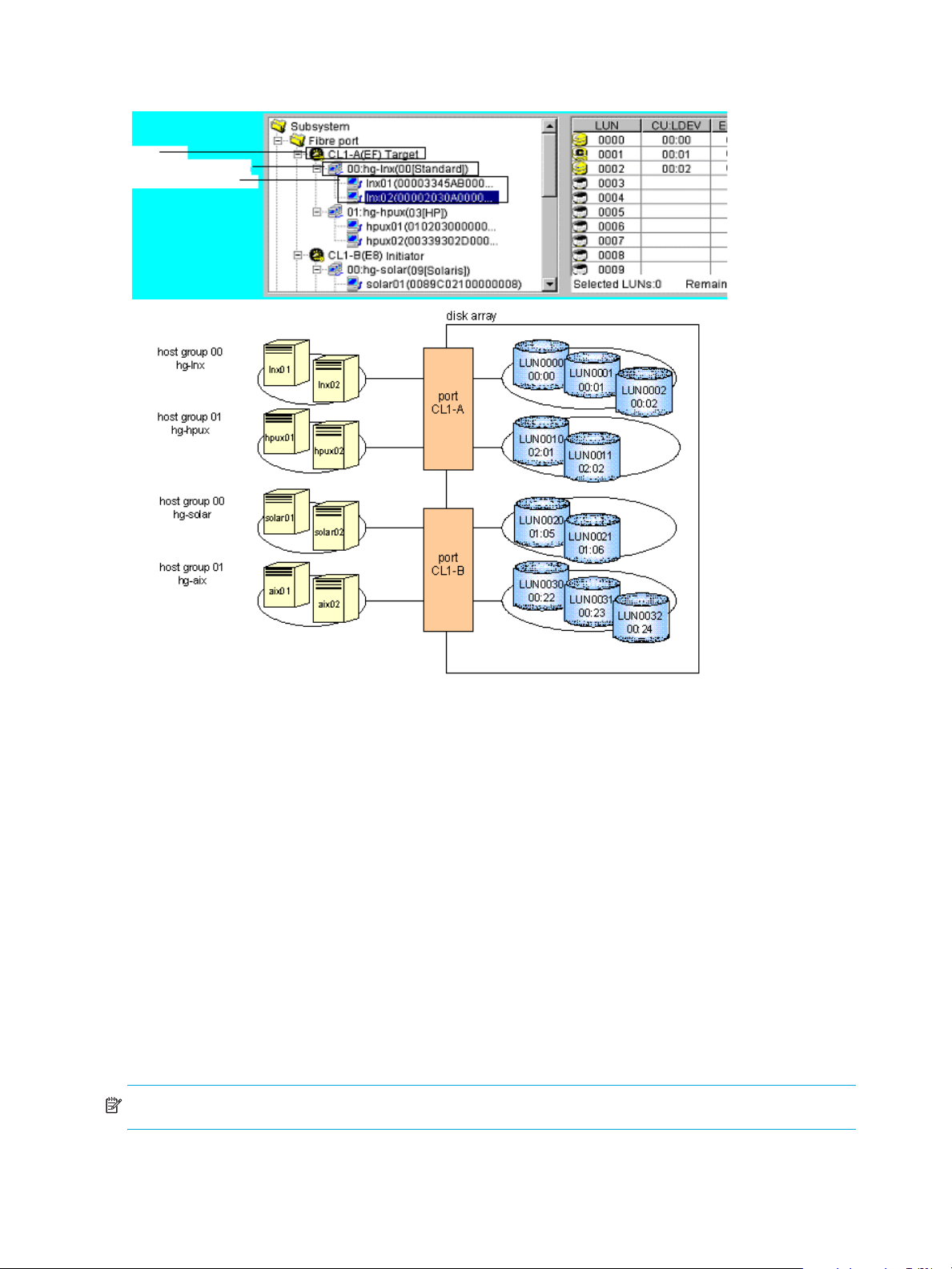
00:01, and 00:02. LU paths are defined between the two hosts in the hg-lnx group and the three logical
volumes.
Por t
Host Storage Domain
Host Groups
Figure 1 LU paths configuration in a Fibre Channel environment
LUN Manager lets you define paths between a single server host and multiple LUs. In Figure 1, both hosts
in the hg-lnx host storage domain can access the three available LUs.
LUN Manager lets you define paths between multiple server hosts and a single LU. In Figure 1, the LU
identified as CU-LDEV 00:00 is accessible to the two hosts in the hg-lnx host storage domain.
In Figure 1, the LUs associated with the hg-lnx domain are addressed by numbers 0 to 2. The address
number of an LU is referred to as the logical unit number (LUN). When HP StorageWorks Continuous
Access XP and other optional features manipulate LUs, they use LUNs to specify the LUs to be manipulated.
You can add, change, and delete LU paths when the system is operational. For example, if new disks or
server hosts are added to your disk array, you can add new LU paths. If an existing server host is to be
replaced, you can delete the corresponding LU paths before replacing the host. You do not need to restart
the system when you add, change, and delete LU paths.
If a hardware failure (such as a CHA failure) occurs, there is a chance that some LU paths are disabled
and some I/O operations are stopped. To avoid this, the system administrator can define alternate LU
paths. If one LU path fails, the alternate path takes over the host I/O.
In a Fibre Channel environment, up to 1,024 LU paths can be defined for one host storage domain. Up to
1,024 LU paths can be defined for one port.
NOTE: You cannot define an LU path to LUN On Demand volumes or volumes reserved by Auto LUN XP.
• Up to 256 host storage domains can be created for one Fibre Channel port. Up to 57,344 host storage
domains can be created for one disk array. The maximum number of ports per subsystem is 224.
12 LUN Manager for the XP10000/XP12000
Page 13
• Up to 255 host groups can be created for one Fibre Channel port.
• You cannot define any LU path to journal volumes.
• You cannot define any LU path to pool volumes.
16-Port FC/CA CHIP product
Although there is not a significant performance gain compared to the 8-port FC/CA CHIP product, the
primary advantage of the 16-port FC/CA CHIP product is its increased FC connectivity (or port count).
High-speed mode is currently unavailable on the 16-port FC/CA CHIP product.
Odd/even LUN data path handling through the processor does not exist on the XP10000/XP12000.
There is no odd/even LUN mapping issue associated with this product. Each processor of the 16-port CHIP
product handles the data flow of two ports (eight total processors for 16 total ports = two ports per
processor).
For load balancing, the two ports serviced by a processor should be considered as one port. Although
volumes can be mapped to both ports handled by a processor, the I/O will go through one processor. For
redundancy and performance reasons, consider distributing the load across multiple CHIPs.
When deciding whether to map volumes to ports (LUN mapping) for host connectivity, after considering
load balancing across processors, there is no reason to not use all 16 ports immediately. After considering
load balancing among processors, there is no reason not to use both ports in the I/O path of one
processor or to use both ports in the I/O path of a processor.
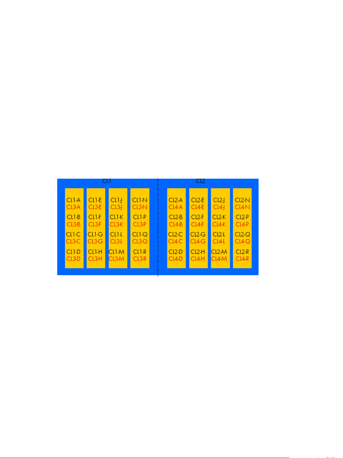
Figure 2 16-Port CHIP pair labeling
Port numbering is as follows: Cluster 1 uses CL1-* and CL3-*, while Cluster 2 uses CL2-* and CL4-*,
where * is an alphabetical character designation of the port such as A, B, C, and so on. Ports A, for
example, CL1-A and CL3-A, share the same processor for I/O purposes.
Host groups
Begin by grouping server hosts into host groups. For example, if HP-UX and Windows hosts are connected
to the disk array, you must create a separate host group for each host type. When this is done, register the
hosts in their corresponding host groups. After hosts are classified into host groups, associate the host
groups with LUs.
LUN Configuration and Security Manager XP user guide for the XP10000/XP12000 13
Page 14
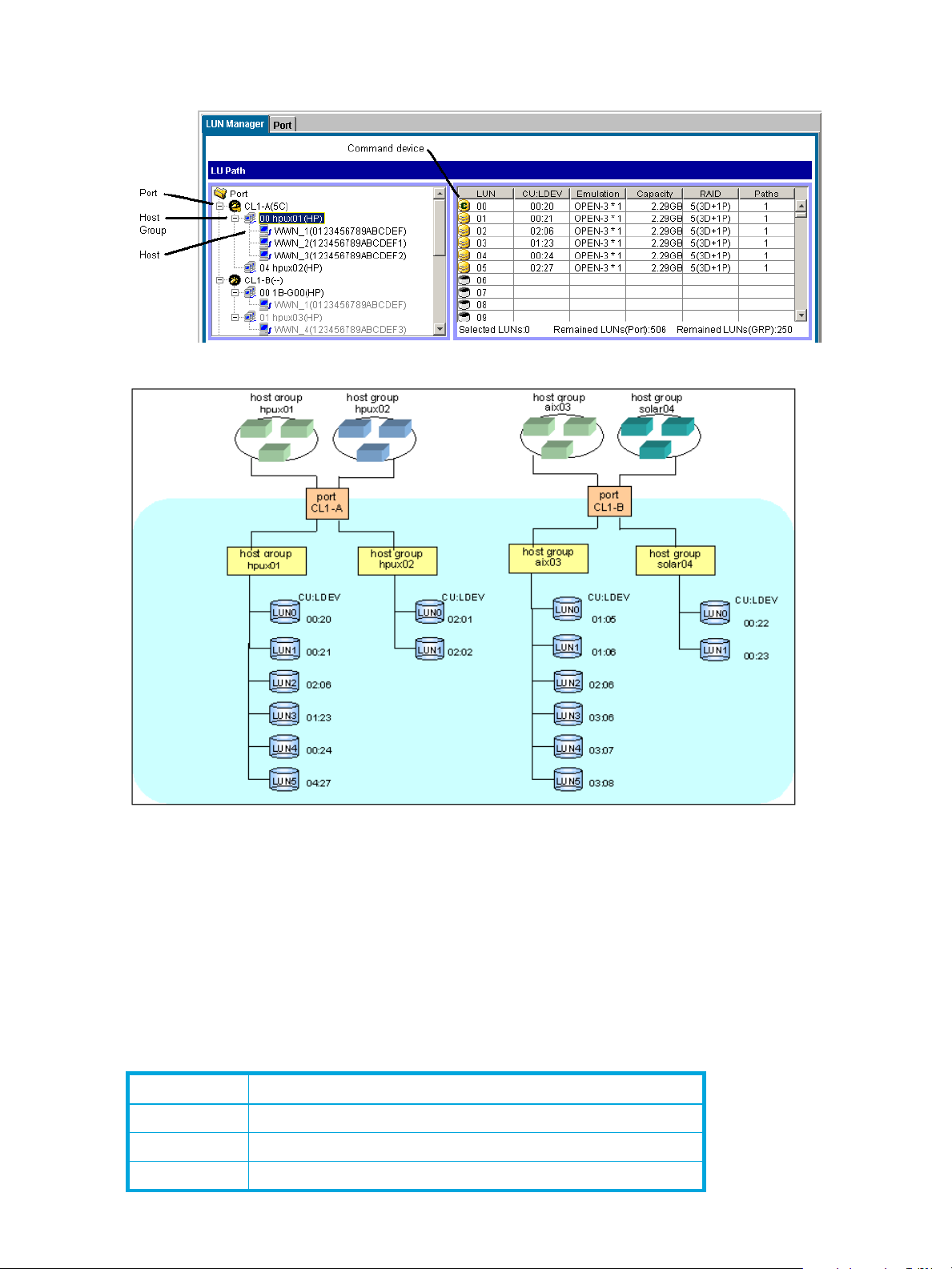
In Figure 3, the host group hpux01 is associated with six LUs. LU paths are defined between the three hosts
in the hpux01 group (WWN_1, WWN_2, WWN_3) and the six logical units LUN00-LUN05.
Figure 3 Host group example 1
Figure 4 Host group example 2
LUN Manager can define paths between a single host and multiple LUs. In Figure 4, each of the three
hosts in the host group hpux01 can access the six LUs. LUN Manager can also define paths between
multiple hosts and a single LU.
Hosts can be members of only one host group for a given port. Host group definitions and members apply
only to the port that they are defined for.
Host modes
As part of registering hosts in host groups, you will be asked for the host mode. Use Table 3 to determine
the host mode.
Table 3 Host modes for host operating systems
Host mode Host operating system
00 Red Hat Linux, IRIX, or Windows1 (Standard)
01 - 03 Reserve
04 DYNIX/ptx (Sequent)
14 LUN Manager for the XP10000/XP12000
Page 15

Table 3 Host modes for host operating systems (continued)
Host mode Host operating system
05 OpenVMS
06 Reserve
07 Tru64
08 HP-UX or Windows
09 Solaris®
0A NetWare
0B Reserve
0C Windows
3, 4
0D, 0E Reserve
0F AIX®
10 - 19 Reserve
1A - 1F Reserve
20 - 29 Reserve
2A, 2B Reserve
2C Windows Extension
2
3, 4
2D - 2F Reserve
29 Solaris
1. For Windows with any FC HBAs when MSCS is not needed.
2. For Windows with D8602 FC HBAs with or without MSCS.
3. For Windows with Emulex or QLogic FC HBAs with or without MSCS.
4. If you register Windows server hosts in a host group, verify that the host mode of the host group is 0C:
Windows or 2C: Windows Extension. If you are thinking about creating LUSE volumes, such as
expanded LUs, consider setting the host mode 2C: Windows Extension to the host group. If the host
mode is 0C: Windows and an LU path is defined for a volume, you cannot execute LUSE operations
on the volume without unmapping the volume first.
5. When registering Sun Cluster server hosts in the host group (Use this host mode both VERITAS Cluster
Server and Sun Cluster are used).
LUN Security
To protect data from unauthorized access, apply security policies to LUNs. LUN Manager can apply LUN
security to ports to safeguard LUs. If a port has the External attribute, you cannot apply LUN security to the
port.
If LUN security is applied, it limits which host can access which LUs. A host can only access LUs associated
with its host group. Hosts cannot access LUs associated with other host groups.
5
LUN Configuration and Security Manager XP user guide for the XP10000/XP12000 15
Page 16
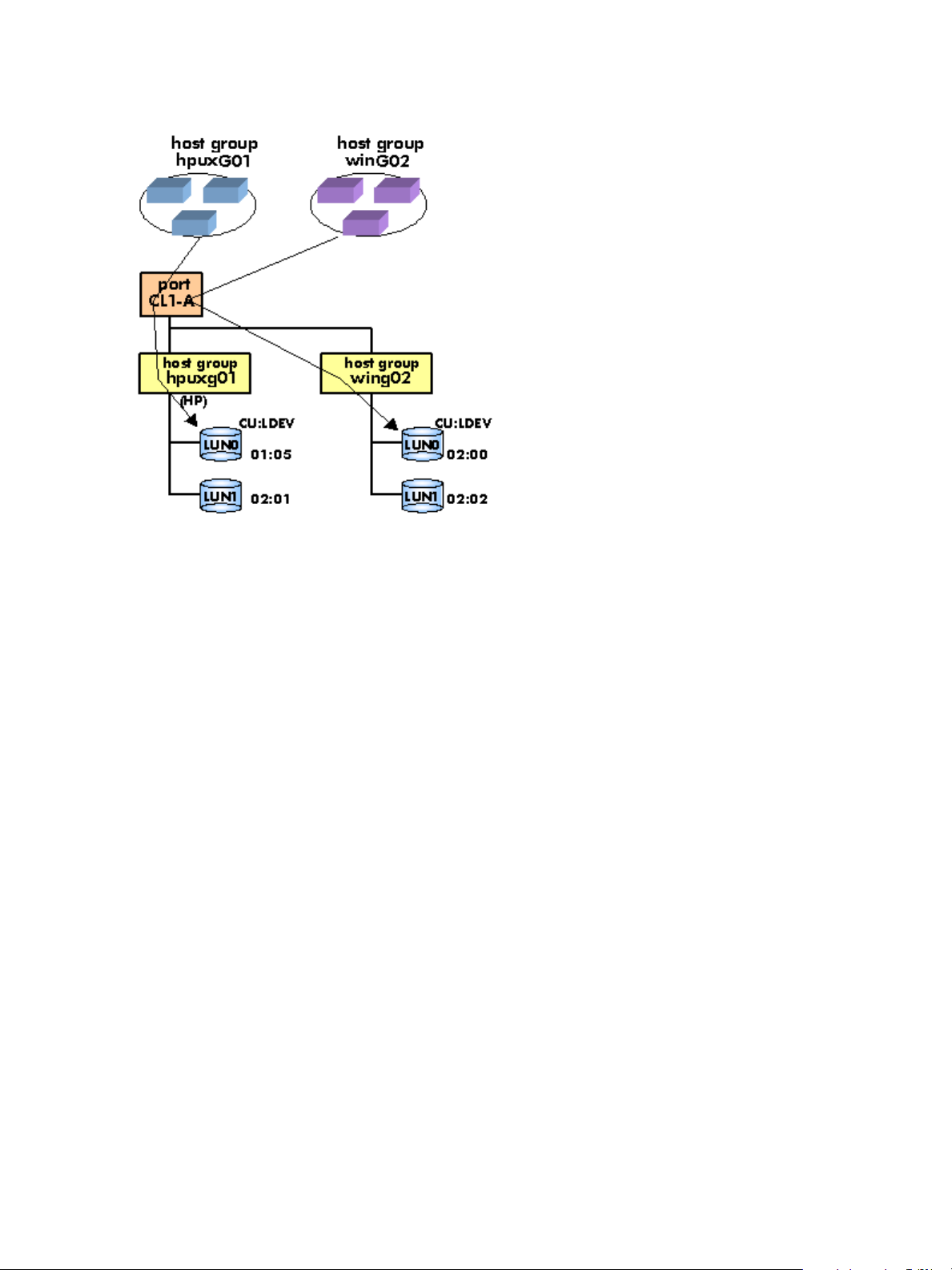
In Figure 5, the hosts in the hpux-G01 group can access LUN0 and LUN1 associated with the same host
group, but cannot access LUN0 and LUN1 in the winG02 host group. The hosts in hpuxG01 can only
access the two LUs, identified by 01:05 and 02:01; the hosts cannot access the LUs 02:00 and 02:02.
Figure 5 Host group example 3 (LUN security)
If LUN security is disabled, the hosts will not be able to access most of the LUs. Hosts will have access to
only those LUs defined in host group 0.
By default, LUN security is disabled on a port, so host group 0 is the only accessible host group reserved
for the port. Initially it contains no LUs or WWNs.
When security is disabled, only LUs defined in host group 0 are accessible to hosts connected to the port,
regardless of any WWNs that may be defined for a host group. After security is enabled, WWNs are
used, permitting or restricting access based on WWN.
If you have more than one host group defined on a port, you can locate host group 0 by disabling LUN
security from the port. When done, the tree display will “gray” out all host groups except host group 0.
RAID Manager command devices
To use RAID Manager commands for Business Copy XP and Continuous Access XP operations, you must
designate at least one LDEV on the disk array as a command device. A command device receives RAID
Manager commands entered from hosts. When you enter a RAID Manager command from a host, the
command is transferred to the target device via the command device.
If you want to restrict access to LUs and by RAID Manager, you can apply command device security in LUN
Manager.
Restrictions
You cannot use the following LDEVs as command devices:
• Volumes that do not have read/write access
• Volumes reserved by Auto LUN
• Continuous Access XP volumes
• BC volumes
• External LUs
• Flex Copy volumes
• Volumes on which VMA is set
• Virtual volumes
16 LUN Manager for the XP10000/XP12000
Page 17

If you want to use a LUSE volume as a command device, you must specify only the first LU as the command
device.
Fibre Channel port attributes
In Fibre Channel environments, you must configure and set addresses for the Fibre Channel ports. You can
enhance system performance by adjusting the data transfer speed at the Fibre Channel ports and
changing the channel adapter mode.
Fibre Channel topologies
Fibre Channel provides the following topologies:
• Fabric: Uses a fabric switch to connect a large number of devices. Each device has the full bandwidth
of 100 MB/sec.
• FC-AL (Fibre Channel-Arbitrated Loop): A shared-bandwidth topology that can connect up to 126
devices (AL ports).
• Point-to-point: A simple Fibre Channel topology in which two devices are connected directly.
When configuring the disk array, use LUN Manager to specify whether the hosts and the disk array are
connected by a fabric switch. Also, you must specify FC-AL or point-to-point in the LUN Manager pane. The
default is FC-AL.
If you are using a fabric switch, consult the switch’s documentation to learn whether FC-AL or point-to-point
should be used. Some fabric switches require that you specify point-to-point to get the system running.
Arbitrated loop physical addresses
You will need to set addresses for Fibre Channel ports. When addressing Fibre Channel ports, you can use
AL-PA (arbitrated loop physical address) or loop IDs as the addresses (see Table 4).
Table 4 AL-PA and loop IDs
AL-PA Loop ID AL-PA Loop ID AL-PA Loop ID AL-PA Loop ID
EF 0 B2 32 72 64 3A 96
E81 B13371653997
E42 AE346E663698
E2 3 AD 35 6D 67 35 99
E1 4 AC 36 6C 68 34 100
E0 5 AB 37 6B 69 33 101
DC 6 AA 38 6A 70 32 102
DA 7 A9 39 69 71 31 103
D9 8 A7 40 67 72 2E 104
D6 9 A6 41 66 73 2D 105
D5 10 A5 42 65 74 2C 106
D4 11 A3 43 63 75 2B 107
D3 12 9F 44 5C 76 2A 108
D2 13 9E 45 5A 77 29 109
D1 14 9D 46 59 78 27 110
CE 15 9B 47 56 79 26 111
CD 16 98 48 55 80 25 112
CC 17 97 49 54 81 23 113
CB 18 90 50 53 82 1F 114
LUN Configuration and Security Manager XP user guide for the XP10000/XP12000 17
Page 18
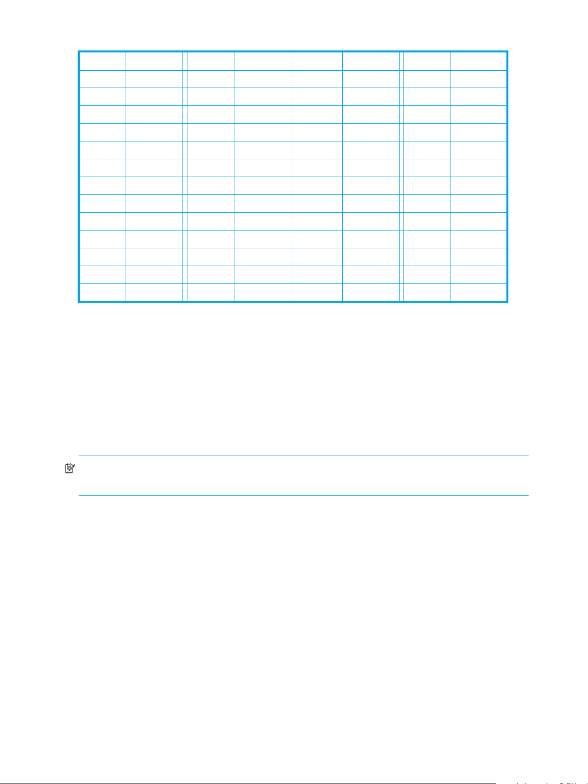
Table 4 AL-PA and loop IDs (continued)
AL-PA Loop ID AL-PA Loop ID AL-PA Loop ID AL-PA Loop ID
CA 19 8F 51 52 83 1E 115
C9 20 88 52 51 84 1D 116
C7 21 84 53 4E 85 1B 117
C6 22 82 54 4D 86 18 118
C5 23 81 55 4C 87 17 119
C3 24 80 56 4B 88 10 120
BC 25 7C 57 4A 89 0F 121
BA 26 7A 58 49 90 08 122
B9 27 79 59 47 91 04 123
B6 28 76 60 46 92 02 124
B5 29 75 61 45 93 01 125
B4 30 74 62 43 94
B3 31 73 63 3C 95
Data transfer speed for Fibre Channel ports
As disk array operation continues, you may notice that a larger amount of data is transferred at some ports
and a smaller amount is transferred at other ports. To improve system performance, set a faster data
transfer speed for ports where a larger amount of data is transferred, and a slower data transfer speed for
ports where a smaller amount of data is transferred.
Standard, high-speed, and high-speed (2 port) modes
The channel adapter boards can operate in standard, high-speed, or high-speed (2-port) mode. Standard
mode is the default. If a channel adapter board satisfies certain conditions, you can set it to high-speed or
high-speed (2 port) mode to improve port performance.
NOTE: High-speed (2 port) mode is available only if firmware version 21.06.22 or later is installed on
the disk array.
High-speed mode can be applied to channel adapter boards that satisfy the following conditions:
• Only one port is planned for use.
• All ports take the same Fibre topology option (on or off).
• All ports take FC-AL as the Connection option.
• All ports use different port addresses and no matching addresses.
• All ports take the same port attribute (Initiator, RCU target, or Target).
If high-speed mode is applied to a channel adapter board, only one of the ports on the channel adapter
board can be used. This port can exclusively use channel processors and fibre optic processors (FOPs) that
would otherwise be reserved for the other ports. Balancing the workload on the processors can improve
system performance.
If high-speed (2 port) mode is applied to a four-port channel adapter board, two ports out of the four ports
cannot be used. The remaining two ports can exclusively use channel processors and FOPs that would
otherwise be reserved for the other two ports.
18 LUN Manager for the XP10000/XP12000
Page 19
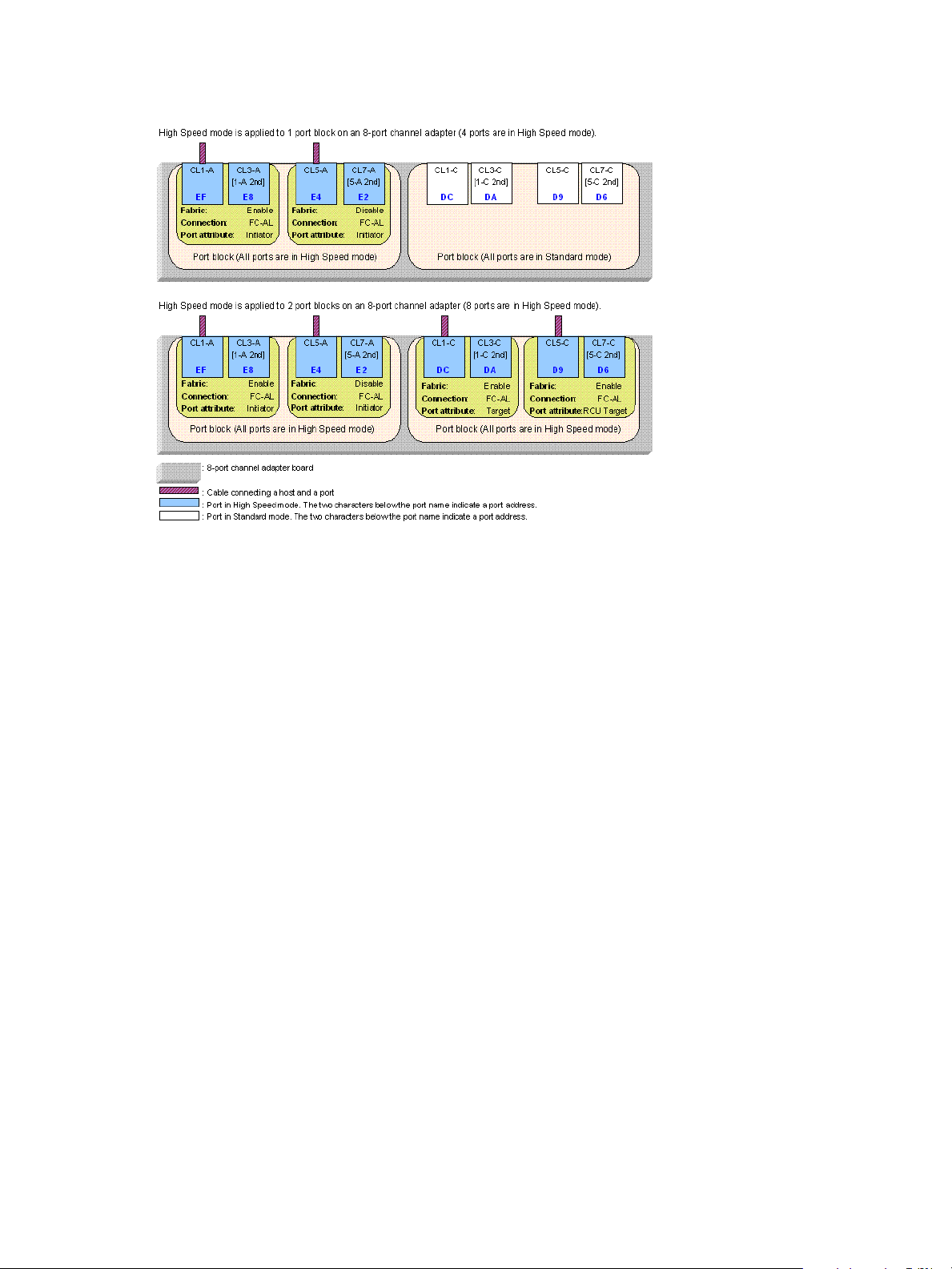
Figure 6 shows an example of High Speed mode applied for one or two port clocks when the channel
adapter board has 8 ports. In case that the channel adapter board has 16 ports, you can also apply High
Speed mode in the same way though there are four port blocks.
Figure 6 Differences between high-speed and high-speed (2 port) modes
If High Speed mode is applied to the four ports in a port block, only two of the ports can be used for
connecting the host. These two ports can exclusively use channel processors and fibre optic processors
(FOPs) that would otherwise be reserved for the other two ports. Therefore, system performance improves.
By balancing workloads on processors, you can expect a greater improvement in system performance.
Before changing the configuration of a port that is being used, perform a backup operation. You cannot
switch between standard and high-speed while you are online to the hosts.
LUN Manager operations
This section includes procedures for performing the most common LUN Manager operations.
Starting LUN Manager
Click LUN Manager in the left pane. The LUN Manager pane appears.
The Command View XP or XP Remote Web Console main pane must be in Modify mode to use LUN
Manager. When the background color of the icon on the right of the pane is light yellow, Command View
XP or XP Remote Web Console is in Modify mode. When the background color is gray, Command View
XP or XP Remote Web Console is in View mode. If you click the grayed icon when the Unlocked icon is
displayed, the icon changes to light yellow and the mode changes to Modify. For more information about
changing modes, see the HP StorageWorks Command View XP User Guide for XP Disk Arrays or the
HP StorageWorks XP Remote Web Console User Guide for XP12000/XP10000.
LUN Configuration and Security Manager XP user guide for the XP10000/XP12000 19
Page 20
NOTE: Storage partition administrators can display information or operate only within the allocated SLPR.
For more information about SLPRs, see the HP StorageWorks XP Disk/Cache Partition User Guide.
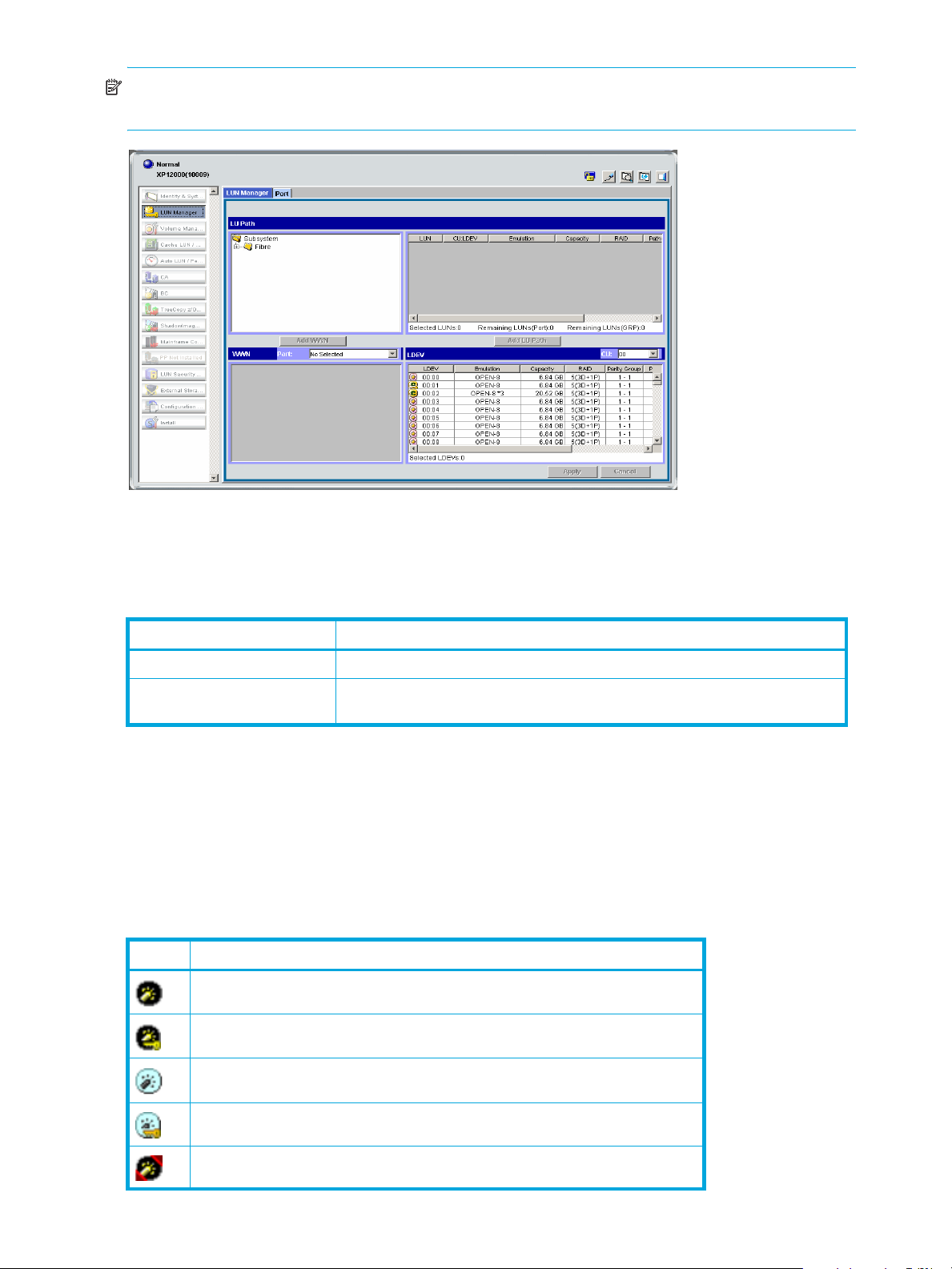
Figure 7 LUN Manager pane
LUN Manager pane
The LUN Manager pane contains the tabs listed in Table 5.
Table 5 LUN Manager tabs
Tab Use this tab to...
LUN Manager Define LU paths and apply LUN security for logical volumes.
Port Configure ports by setting the topology and port addresses (”Starting Port
LU Path tree
The LU Path tree on the upper left of the LUN Manager tab lists Fibre Channel ports in the disk array and
hosts connected to them. Hosts are identified by nicknames and WWNs and are classified by host groups.
The LU Path tree may contain different folders: Fibre Channel, and so on.
Fibre Channel folder
The following Fibre Channel port icons are used in the LU Path tree:
Table 6 Fibre Channel port icons for LUN Manager operations
Icon Status
A short-wave port in standard mode without LUN security
A short-wave port in standard mode with LUN security
Operations” on page 31).
A long-wave port in standard mode without LUN security
A long-wave port in standard mode with LUN security
A short-wave port in high-speed mode without LUN security
20 LUN Manager for the XP10000/XP12000
Page 21
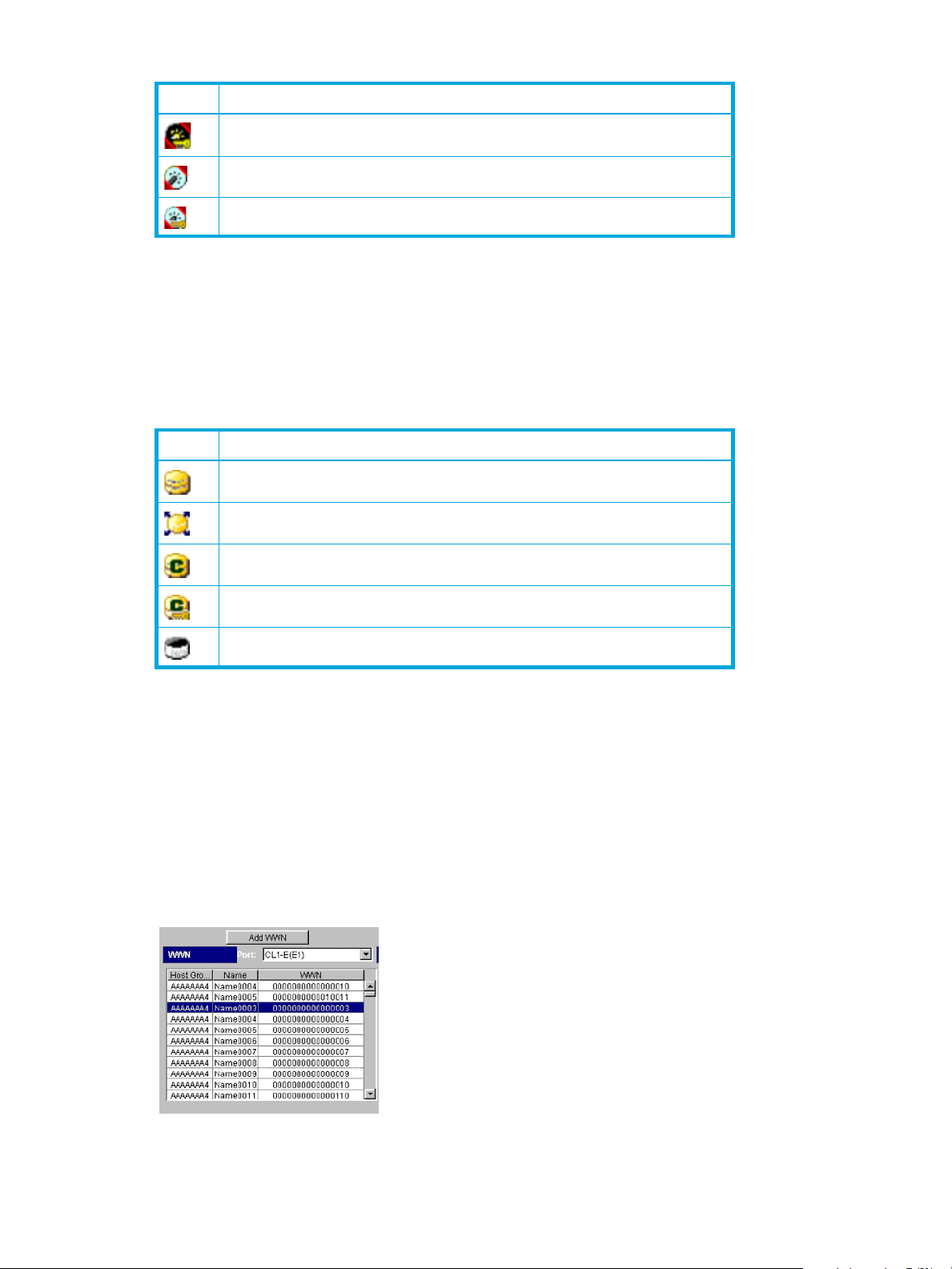
Table 6 Fibre Channel port icons for LUN Manager operations (continued)
Icon Status
LU Path table
On the right side of the LU Path tree is a table that displays LU Path information about the hosts in the tree.
The table contains the following information:
• LUN: LUNs (address numbers) assigned to LUs, which are LDEVs that can be accessed by hosts. If no
Table 7 LUN icons for LUN Manager operations
Icon Status
A short-wave port in high-speed mode with LUN security
A long-wave port in high-speed mode without LUN security
A long-wave port in high-speed mode with LUN security
paths are defined, the other table columns are blank.
The following icons indicate status.
A logical volume to which an LU path is defined
An expanded LU
A command device
A command device with security enabled
A LUN to which no LU path is defined
• CU:LDEV: The CU image and LDEV numbers. If an LDEV number ends with #, the logical volume is an
external LU. If an LDEV number ends with V, the logical volume is a virtual volume.
• Emulation: Emulation type for each LDEV
• Capacity: Size of each LDEV
• RAID: RAID level for each LDEV. If the logical volume is an external LU or virtual volume, the RAID
column displays a hyphen (-) instead of a RAID level.
• Paths: Number of alternate paths, if any
• VMA:Access Attribute: Access attribute of each LDEV. If a VMA is set on a logical volume, VMA:
appears at the beginning of the access attribute.
WWN name table
Figure 8 WWN name table
LUN Configuration and Security Manager XP user guide for the XP10000/XP12000 21
Page 22

When you select a Fibre Channel port in the LU Path tree, the WWN table appears in the lower-left corner
of the LUN Manager pane. The WWN table lists host bus adapters that are connected to Fibre Channel
ports on the disk array.
The table contains the following information:
• A list of ports
• Host Group: Host groups are used to classify servers (hosts) connected to the disk array. You can create
• Name: Indicates nicknames for hosts. Nicknames can be specified in the LUN Manager pane.
• WWN: Each worldwide name represents one host.
LDEV table
The LDEV table in the lower-left corner of the LUN Manager tab lists LDEVs in the disk array. The LDEV
table does not list Auto LUN-reserved LDEVs.
The table contains the following information:
• A list of CU images
• LDEV: A combination of the CU image number and LDEV number that identifies an LDEV. If an LDEV
Table 8 LDEV icons for LUN Manager operations
host groups in the LUN Manager pane.
number ends with #, the logical volume is an external LU. If an LDEV number ends with V, the logical
volume is a virtual volume.
The following icons indicate LDEV status:
Icon Status
Normal logical volume
Expanded LU
A VSC volume
A command device
A command device with security enabled
• Emulation: Emulation type for each LDEV
• Capacity: Size of each LDEV
• RAID: RAID level for each LDEV. If the logical volume is an external LU or a virtual volume, the RAID
column displays a hyphen (-) instead of a RAID level.
• Parity Group: Displays names of parity groups. If a parity group name begins with E, the parity group
consists of one or more external LUs. If a group name begins with V, the group is a V-VOL group
consisting of one or more virtual volumes.
• Paths: The number of alternate paths, if any
• VMA:Access Attribute: Access attribute of each logical volume. If a VMA is set on a logical volume,
VMA: appears at the beginning of the access attribute.
Buttons
• Apply: Applies settings in the pane to the disk array
• Cancel: Cancels settings in the pane
• Add LU Path: Adds LUs to LU Path table
• Add WWN: Registers host bus adapters in a host group. Applies to Fibre Channel ports only.
22 LUN Manager for the XP10000/XP12000
Page 23
Defining LU paths
To configure a Fibre Channel environment, complete the following major steps:
1. Find the WWNs of the host bus adapters connected to the Fibre Channel ports.
2. Create host groups (”Creating host groups” on page 23).
3. Register hosts in host groups (”Registering hosts in host groups” on page 24).
4. Associate host groups to logical volumes (”Associating host groups to logical volumes” on page 26).
Creating host groups
You can connect multiple server hosts of different platforms to one port of your disk array. When
configuring the system, you must group server hosts connected to the disk array by host groups. For
example, if HP-UX and Windows hosts are connected to a port, create a host group for each host type.
1. Start LUN Manager, and display the LUN Manager pane (Figure 7).
2. In the LU Path tree, locate the port and verify that LUN security is enabled.
NOTE: If the port icon has a key ( ), LUN security is enabled.
If LUN security is not enabled, right-click the port and select Disable->Enable in the shortcut menu.
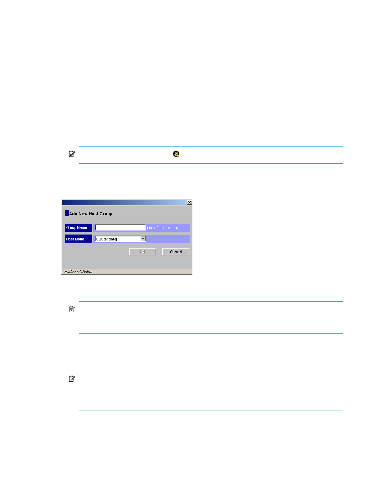
3. After LUN security is enabled, right-click the port in the LU Path tree and select Add New Host Group.
The Add New Host Group dialog box appears.
Figure 9 Add New Host Group pane
4. In the Group Name box, enter the host group name.
NOTE: It is convenient to name each host group after the host platform. For example, if you are
creating a host group for Windows NT
Host group names are case sensitive and can have up to 32 characters.
5. In the Host Mode list, select a host mode. Host groups on the same port can have different host modes.
6. If necessary, select Option, and select the host mode options. For detailed information about host mode
options, see Table 9 on page 24.
NOTE: After you select Option, the pane expands to display check boxes. The check boxes are
numbered sequentially from left to right. The left-most check box on the upper row is #0, and the
check box immediately to the right is #1, and so on. The numbers indicate option numbers; select
check box #0 to select option #0.
7. Click OK. The host group name and the host mode appear in blue in the LU Path tree.
8. In the LUN Manager main pane, click Apply. A confirmation message appears.
® hosts, the host group name could be WNT or WinNT.
LUN Configuration and Security Manager XP user guide for the XP10000/XP12000 23
Page 24
9. Click OK. The settings are applied to the disk array.
The next step is to register hosts to the appropriate host group.
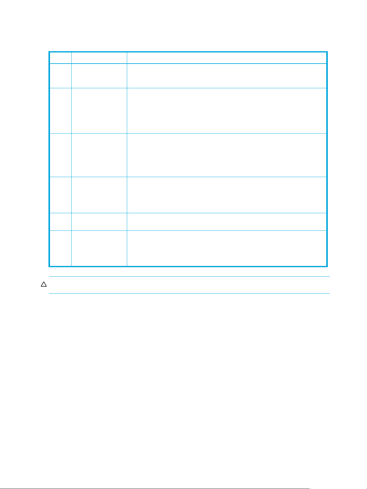
Table 9 Host mode options
No. Host Mode option When to select option
2VERITAS Database
Edition/Advanced
Cluster
6 TPRLO When all the following conditions are satisfied:
7Automatic
recognition function
of LUN
12 Undisplay function of
ghost LUN
13 SIM report at link
failure
14 HP TruCluster with
TrueCopy function
When VERITAS Database Edition/Advanced Cluster for Real Application Clusters
or VERITAS Cluster Server 4.0 (I/O fencing function) is used
• The host mode 0C Windows or 2C Windows Extension is used
• The Emulex host bus adapter is used
• The mini-port driver is used
• TPRLO=2 is specified for the mini-port driver parameter of the host bus adapter
When all the following conditions are satisfied:
• The host mode 00 Standard or 09 Solaris is used
• SUN StorEdge SAN Foundation Software Version 4.2 or later is used
• You want to automate recognition of increase and decrease of devices when a
genuine SUN HBA is connected
When all the following conditions are satisfied:
• The host mode 08 HP is used
• You want to suppress creation of device files for devices to which the paths are
not defined
When the user wants to be informed by SIM (service information message) that the
number of link failures detected between ports exceeds the threshold.
When all the following conditions are satisfied:
• The host mode 07 Tru64 is used
• You want to use TruCluster to set a cluster to the Continuous Access XP P-VOL
and S-VOL, respectively
CAUTION: Do not select options other than those listed in Table 9.
Registering hosts in host groups
Before you can set LU paths, you must register hosts in host groups. For example, if HP-UX and Windows
hosts are connected to a port, you must register them separately in two different host groups.
When registering a host, you can assign a nickname to the host bus adapter. If you assign a nickname,
you will be able to easily identify each host bus adapter in the LUN Manager main pane. Although
WWNs are also used to identify each host bus adapter, a nickname is more helpful because you can
name host bus adapters after the host installation site or the host owners.
When using nicknames, note the following:
• A nickname can consist of up to 32 ASCII characters (letters, numerals, and symbols). You cannot use
the following characters for nicknames:
\ / : , ; * ? " < > | ~
• You cannot use the space character for the first or the last nickname character.
• Nicknames are case sensitive. For example, hp and HP are different nicknames.
To register hosts in a host group:
1. Start LUN Manager, and display the LUN Manager pane (Figure 7).
24 LUN Manager for the XP10000/XP12000
Page 25
2. In the LU Path tree, locate the port the host group belongs to and verify that LUN security is enabled.
NOTE: If the port icon has a key ( ), LUN security is enabled.
If LUN security is not enabled, right-click the port and select Disable->Enable in the shortcut menu.
3. If the desired host has never been connected via a cable to another port in the disk array, skip to
step 9.
4. In the Port list on the upper right corner of the WWN table (Fibre Channel), select the port to which the
desired host is connected.
5. Select the desired host bus adapter from the WWN table.
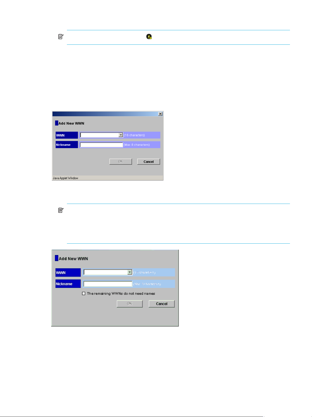
6. Select a host group from the tree, and click Add WWN. The Add New WWN (Fibre Channel) dialog
box appears.
Figure 10 Add New WWN dialog box
7. To assign a nickname to the host bus adapter, enter the nickname in the Nickname box and click OK.
NOTE: If you select two or more host bus adapters, the Add New WWN dialog box displays
repeatedly to let you assign a nickname to each selected HBA (see Figure 11). If you do not need to
assign nicknames to HBAs, select the The remaining WWNs do not need names check box, and
click OK. If you select this option, the Add New WWN dialog box does not prompt you for
additional nicknames.
Figure 11 Add New WWN dialog box (when registering a host that was previously connected to the disk
array)
8. Skip to step 12. If the desired host has never been connected via a cable to any port in the array, only
step 9 through step 11 apply.
9. Right-click the host group and select Add New WWN. The Add New WWN dialog box appears (see
Figure 10).
10.Select the desired host bus adapter from the WWN list. If the host bus adapter is not in the list, enter
the WWN in the box.
LUN Configuration and Security Manager XP user guide for the XP10000/XP12000 25
Page 26

11.If necessary, enter a nickname for the host bus adapter.
12.Click OK. The new WWN and nickname appear below the selected host group in the LU Path tree.
13.Click Apply in the LUN Manager main pane. A confirmation message appears.
14.Click OK. The settings are applied to the disk array.
NOTE: For Fibre Channel environments only: If the WWN table (located in the lower-left corner of the
pane) includes a host that you want to register, you can register the host by selecting the host group in the
LU Path tree, selecting the host from the WWN table, and then clicking Add WWN.
Associating host groups to logical volumes
You can use LUN Manager to define LU paths by associating host groups to logical volumes. For example,
if you associate a group of three hosts with logical volumes, LU paths are defined between the three hosts
and the logical volumes.
1. Start LUN Manager, and display the LUN Manager pane (Figure 7).
2. In the LU Path tree on the LUN Manager main pane, select a host group.
3. In the CU list above the LDEV table, select a CU number. The LDEV table shows LDEVs in the CU.
4. In the LDEV table, select one or more LDEVs. Press the Ctrl key to select multiple LDEVs.
5. In the LU Path table, select the LUs.
6. Click Add LU Path. A dialog box prompts you to confirm the LU Paths to be defined.
7. Click OK. The settings are shown in blue in the LU Path table.
8. Click Apply in the LUN Manager main pane. A confirmation message appears.
9. Click OK. The settings are applied to the disk array.
Changing or viewing LU path settings
Deleting LU paths
NOTE: Do not remove LU paths when host I/O is in progress.
1. Start LUN Manager, and display the LUN Manager pane (Figure 7).
2. In the LU Path tree on the LUN Manager main pane, select a port.
3. In the LU Path table, select one or more LUNs to which LDEVs are assigned (If an LDEV is assigned to a
LUN, the columns to the right of the LUN column are not empty).
4. Right-click the selected port and select Release LU Path. A dialog box displays information about the LU
paths to be deleted.
5. Click OK. The settings are shown in blue in the LU Path table.
6. Click Apply in the LUN Manager main pane. A confirmation message appears.
7. Click OK. The settings are applied to the disk array.
Changing the name and host mode of a host group
Before changing the host mode of a host group, back up the data on the host group’s port. The operation
for changing host mode should not be destructive, but data integrity cannot be guaranteed without a
backup.
To change the host mode for host group 0, port security can be enabled or disabled. For all other host
groups, you must enable port security before changing the host mode.
1. Start LUN Manager, and display the LUN Manager pane (Figure 7).
26 LUN Manager for the XP10000/XP12000
Page 27

2. In the LU Path tree on the LUN Manager main pane, right-click the host group and select Change Host
Group. The Change Host Group dialog box appears.
Figure 12 Change Host Group dialog box
NOTE: After you select the Option button, the pane expands to display check boxes. The check
boxes are numbered sequentially from left to right. The left-most check box on the upper row is #0,
and the check box immediately to the right is #1, and so on. The numbers indicate option numbers;
select check box #0 to select option #0.
3. To change the name of the host group, enter a new name in the Group Name box.
4. To change the host mode, select the new host mode from the Host Mode list.
5. If necessary, select Option, and select the host mode options. For detailed information about host mode
options, see Table 9 on page 24.
6. Click OK. The settings are shown in blue in the LU Path table.
7. Click Apply in the LUN Manager main pane. A confirmation message appears.
8. Click OK. The settings are applied to the disk array.
Deleting host groups
You cannot delete the host group 0 (zero). If you want to remove all the WWNs and LU paths from the host
group 0, you must initialize the host group 0 (”Initializing the host group 0 (zero)” on page 27).
1. Start LUN Manager, and display the LUN Manager pane (Figure 7).
2. In the LU Path tree on the LUN Manager main pane, right-click a host group and select Delete Host
Group. A confirmation message appears.
3. Click Yes to delete the host group. The host group you specified is removed from the LU Path tree.
4. Click Apply in the LUN Manager main pane. A confirmation message appears.
5. Click OK. The settings are applied to the disk array.
Initializing the host group 0 (zero)
Initializing the host group 0 sets the group to its default state. This process:
• Removes all the WWNs from the host group 0 and all the LU paths related to the host group 0.
• Changes the host mode of the host group 0 to Standard and initializes the host group name. For
example, if you initialize the host group 0 for the port CL1-A, the name of the host group 0 will change
to 1A-G00.
1. Start LUN Manager, and display the LUN Manager pane (Figure 7).
2. In the LU Path tree on the LUN Manager main pane, right-click the host group 0 and select Clear Host
Group. A confirmation message appears.
LUN Configuration and Security Manager XP user guide for the XP10000/XP12000 27
Page 28

3. Click Yes.
• The host mode and host group name are changed in the LU Path tree.
• WWNs are removed from host group 0.
• LU paths are removed from the LU Path table.
• The LUNs corresponding to the removed LU paths are shown in blue.
4. Click Apply in the LUN Manager main pane. A confirmation message appears.
5. Click OK. The settings are applied to the disk array.
Changing WWNs and nicknames
1. Start LUN Manager, and display the LUN Manager pane (Figure 7).
2. In the LU Path tree, locate the port the HBA is connected to and verify that LUN security is enabled.
NOTE: If the port icon has a key ( ), LUN security is enabled.
If LUN security is not enabled, right-click the port and select Disable->Enable in the shortcut menu.
3. In the LU Path tree, right-click the WWN and select Change WWN & Nickname. The Change WWN &
Nickname dialog box appears.
Figure 13 Change WWN & Nickname dialog box
\
If the selected WWN is not registered in a host group, Figure 13 is not displayed.
4. Enter the WWN appropriate box, or select it from the list.
5. In the Nickname box, enter the new nickname.
6. If necessary, select the Apply this change to other ports, too check box.
If this check box is selected, the change will affect other ports. For example, if you select a host bus
adapter located beneath ports CL1-A and CL2-A in the tree, and you change the host bus adapter
name under port CL1-A, the host bus adapter will also be renamed under port CL2-A.
NOTE: The change in the pane will not affect any port that satisfies at least one of the following
conditions:
• LUN security is OFF.
• The resulting nickname is already used as the nickname of a host bus adapter connected to the
port.
• The resulting nickname is already used as the name of a host group (that is, a host storage
domain) in the port.
• The resulting WWN exists in the port.
28 LUN Manager for the XP10000/XP12000
Page 29

7. Click OK.
The changes you made are shown in blue. If you selected the Apply this change to other ports, too
check box, the Check WWNs dialog box appears. To accept the changes to the other ports, click OK.
Figure 14 Check WWNs dialog box
8. Click Apply in the LUN Manager main pane. A confirmation message appears.
9. Click OK. The settings are applied to the disk array.
Deleting HBAs from host groups
1. Start LUN Manager, and display the LUN Manager pane (Figure 7).
2. In the LU Path tree, right-click the HBA and select Delete WWN. A confirmation message appears.
3. Click Yes. The WWN you specified is removed from the LU Path tree.
4. Click Apply in the LUN Manager main pane. A confirmation message appears.
5. Click OK. The settings are applied to the disk array.
Deleting unneeded WWNs from the WWN table
If you disconnect a host that has been connected through a cable to your disk array, the WWN for the
host remains in the WWN table of the LUN Manager pane until you remove it.
1. Start LUN Manager, and display the LUN Manager pane (Figure 7).
2. In the WWN table, locate the WWN that is not registered in any host group.
NOTE: If the Host Group column is blank, the WWN is not registered in any host group.
3. Right-click the WWN and select Erase WWN.
4. Click Apply in the LUN Manager main pane. A confirmation message appears.
5. Click OK. The settings are applied to the disk array.
Viewing a list of concatenated parity groups
The XP10000/XP12000 supports concatenation of parity groups. If parity groups are concatenated, a
logical volume can be dispersed across the concatenated parity groups. Dispersal of logical volumes can
provide faster access to data (particularly, faster sequential access to data).
1. Start LUN Manager, and display the LUN Manager pane (Figure 7).
2. In the LDEV table, right-click a logical volume (an LDEV).
If the parity groups are concatenated, the Concatenation List command is available in the shortcut
menu.
3. Select Concatenation List. The Concatenation List dialog box appears.
4. Click OK to return to the LUN Manager main pane.
LUN Configuration and Security Manager XP user guide for the XP10000/XP12000 29
Page 30
Defining alternate paths
LUN Manager can define alternate paths. If an LU path fails, you can switch to its alternate path.
To create an alternate path, copy the original path from one port to another. For example, to define an
alternate for the LU path between the CL1-A port and logical volume 00:01, copy the LU path from the
CL1-A port to another port.
If you want to define alternate paths when LUN security is removed, you must redefine the LU path.
Copying paths from one Fibre Channel to another
CAUTION: Before performing the following steps, see ”Restrictions on port operations” on page 35 for
important information.
1. Start LUN Manager, and display the LUN Manager pane (Figure 7).
2. In the LU Path tree, locate the port that you want to use as the copy destination and verify that LUN
security is enabled.
NOTE: If the port icon has a key ( ), LUN security is enabled.
If LUN security is not enabled, right-click the port and select Disable->Enable in the shortcut menu.
3. To copy all the LU paths defined to a host group, complete the following steps. To copy some LU paths,
skip to step 4.
a. Right-click a host group in the tree and select Copy. The selected host group turns green.
b. Right-click the copy destination port and select Paste.
4. To copy some, but not all of the LU paths defined to a host group, complete the following steps. To copy
all LU paths, see step 3.
a. Select a host group in the LU Path tree.
b. In the LU Path table, select one or more LUNs to which volumes are assigned.
c. Right-click the selection and select Copy Paths in the shortcut menu. The selected LUNs turn green.
d. Double-click the copy destination port.
e. Right-click the copy destination host group and select Paste Paths.
5. Click Apply in the LUN Manager main pane. A confirmation message appears.
6. Click OK. The settings are applied to the disk array.
Viewing alternate paths
1. Start LUN Manager, and display the LUN Manager pane (Figure 7).
2. From the LUN Manager main pane, do one of the following:
• In the LU Path table, select a LUN containing one or more paths.
• In the LDEV table, select an LDEV containing one or more paths.
3. Right-click the selection and select Alternate Paths. The Alternate Paths dialog box appears.
4. Click OK.
Deleting WWNs
1. In the LU Path tree, right-click a WWN and select Delete WWN. A confirmation message appears.
NOTE: If the selected WWN is not registered in a host group, the Delete WWN command is not
available.
2. Click Yes. The selected WWN is no longer listed in the LU Path tree.
3. Click Apply in the LUN Manager main pane. A confirmation message appears.
30 LUN Manager for the XP10000/XP12000
Page 31

4. Click OK. The settings are applied to the disk array.
Applying and removing LUN security
By default, LUN security is not applied to any ports. When configuring your system, you must apply LUN
security to the ports. If a port has the External attribute, you cannot apply LUN security to the port. The
icon indicates a port without LUN security and changes to the icon when LUN security is applied.
1. Start LUN Manager, and display the LUN Manager pane (Figure 7).
2. Right-click a port in the LU Path tree.
a. To apply LUN security, select Disable->Enable.
b. To remove LUN security, Enable->Disable.
A confirmation message appears.
3. Click Yes. The changes are shown in blue.
4. Click Apply in the LUN Manager main pane. A confirmation message appears.
5. Click OK. The settings are applied to the disk array.
Creating RAID Manager Command Devices
To enter RAID Manager commands, set up at least one LU as a command device.
The icon indicates an LDEV that is not a command device and changes to the icon when set to a
command device. When security is enabled, the icon changes to .
Setting an LU as a command device
1. Start LUN Manager, and display the LUN Manager pane (Figure 7).
2. In the LU Path tree, double-click a port and then select a host group.
3. In the LU Path or LDEV table, right-click the LUN and select Command Device: OFF->ON. A confirmation
message appears.
NOTE: If the shortcut menu includes the item Command Device: ON->OFF, the logical device is
already specified as a command device and you do not need to complete this procedure.
4. Click Yes. The changes are shown in blue.
5. Click Apply in the LUN Manager main pane. A confirmation message appears.
6. Click OK. The settings are applied to the disk array.
Stopping the use of an LU as a command device
Right-click the command device and select Command Device: ON->OFF.
Applying command device security
Right-click the command device and select Cmd. Dev. Security: OFF->ON.
Removing command device security
Right-click the command device and select Cmd. Dev. Security: ON->OFF.
Port Operations
Use the Port tab in the LUN Manager pane to configure Fibre Channel ports in your disk array. You can
also use this pane to modify the port configuration when the disk array is operating.
Starting Port Operations
1. Click LUN Manager in the left pane. The LUN Manager pane appears.
LUN Configuration and Security Manager XP user guide for the XP10000/XP12000 31
Page 32

2. Click the Port tab. The Port pane appears.
Figure 15 Port pane
NOTE: The storage partition administrators can display ports and operate within only the allocated SLPR.
For more information about SLPRs, see the HP StorageWorks XP Disk/Cache Partition User Guide.
Port pane
The Port pane includes the package tree, port table, and change port mode box.
Package tree
Use this tree to select the port. The Fibre folder appears under the Subsystem folder at the top of the tree.
When you double-click the Fibre folder, the folder opens and lists all Fibre Channel channel adapter (CHA)
packages. When you double-click a CHA package, port blocks appear below the channel adapter. When
you right-click a CHA package, you can choose standard mode, high-speed mode, or high-speed (2 port)
mode.
NOTE: High-speed (2 port) mode is available only if the XP disk array has firmware version 21.06.22 or
later installed.
The following icons are used to indicate status:
Table 10 Channel adapter package icons for Port operations
Icon Status
A short-wave CHA package in standard mode (Fibre Channel)
A long-wave CHA package in standard mode
A short-wave CHA package in high-speed or high-speed (2 port) mode
A long-wave CHA package in high-speed or high-speed (2 port) mode
32 LUN Manager for the XP10000/XP12000
Page 33

Port table
This table appears when you select an icon under the Fibre folder in the Package tree.
If you select a channel adapter in the tree, this table displays all ports on the channel adapter.
If you select a port block, this table displays all ports in the port block.
The table lists the following for Fibre Channel CHA packages:
• Port Name: Displays port names
• Type: Fibre indicates a Fibre Channel port, used for connecting open system hosts. MF-Serial indicates
an ESCON
• Host Speed: Specifies the data transfer speed for Fibre Channel ports. If Auto is selected, the disk array
automatically sets the data transfer speed to 1 GB/sec or 2 GB/sec.
• Addr (Loop ID): Displays addresses of ports. You can change port addresses.
• Fabric: Specify ON if a fabric switch is used, or OFF if no fabric switch is used
• Connection: Specifies the topology. The default is FC-AL. Some fabric switches require you to specify
point-to-point topology. Check the switch’s documentation.
• Attribute: Indicates whether the port is an initiator port, target port, RCU target port, or external port
• WWN: Displays WWNs of ports.
® port, used for connecting mainframe hosts.
Change Port Mode box
This is displayed when you select an icon under the Fibre folder in the Package tree.
Use this box to change information in the Port table.
Setting the Fibre Channel Topology
1. Start LUN Manager, and display the LUN Manager pane (Figure 7).
2. In the Port table or the Select a Port list, select a Fibre Channel port.
3. If a fabric switch is used, select ON in the Fabric list in the Mode area. If a fabric switch is not used,
select OFF in the Fabric list.
4. In the Connection list, select FC-AL or P-to-P.
If a fabric switch is used, consult the switch documentation to check if it requires point-to-point topology.
5. Click Set. A confirmation message appears.
6. Click OK. The settings are applied to the Port table (shown in blue), but not to the disk array.
7. Click Apply. A confirmation message appears.
8. Click OK. The settings are applied to the disk array.
Setting Fibre Channel Port Addresses
1. Start LUN Manager, and display the LUN Manager pane (Figure 7).
2. In the Port table or the Select a Port list, select a Fibre Channel port.
3. In the Fibre Address list in the Mode area, select an address.
4. Click Set. A confirmation message appears.
5. Click OK. The settings are applied to the Port table (shown in blue), but not to the disk array.
6. Click Apply. A confirmation message appears.
7. Click OK. The settings are applied to the disk array.
Setting the Data Transfer Speed
1. Start LUN Manager, and display the LUN Manager pane (Figure 7).
2. In the Port table or the Select a Port list, select a Fibre Channel port.
3. In the Host Speed list in the Mode area, select a data transfer speed.
4. Click Set. A confirmation message appears.
5. Click OK. The settings are applied to the Port table (shown in blue), but not to the disk array.
LUN Configuration and Security Manager XP user guide for the XP10000/XP12000 33
Page 34
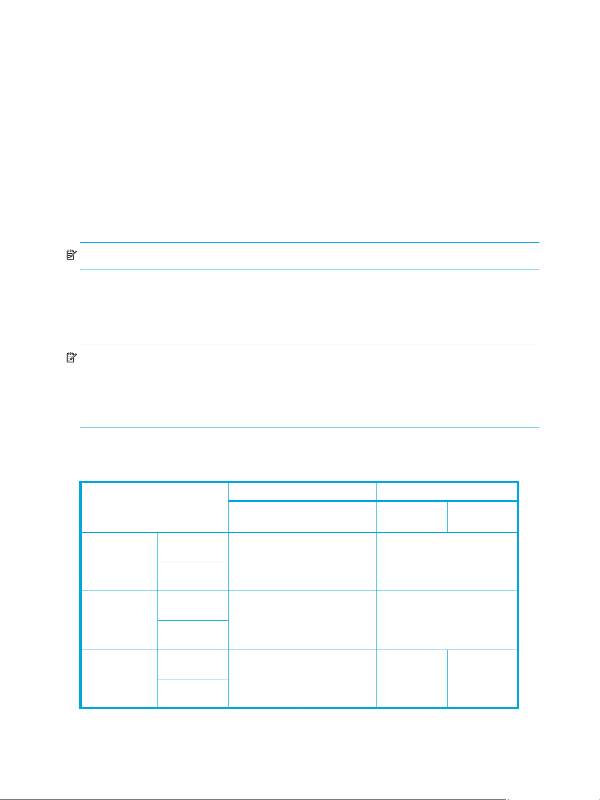
6. Click Apply. A confirmation message appears.
7. Click OK. The settings are applied to the disk array.
Switching to standard or high-speed mode
Channel adapter boards can be set for standard or high-speed mode. If possible, apply high-speed mode
to channel adapters to improve the system performance. Be aware that you can only apply high-speed or
high-speed (2 port) mode to channel adapters that satisfy certain requirements.
1. Start LUN Manager, and display the LUN Manager pane (Figure 7).
2. In the Package tree on the Port pane, right-click a channel adapter (CHA) package. A shortcut menu
appears. The current mode is preceded by a bullet.
3. Select the mode that you want. A confirmation message appears.
4. Click OK.
5. Click Apply. A confirmation message appears.
6. Click OK. The settings are applied to the disk array.
NOTE: Storage partition administrators cannot apply High Speed mode.
Operational restrictions
The success of some LUN Manager activities depends on the status of the security switch and whether I/O
is active or inactive to the port or LUN. The following tables describe those restrictions.
NOTE:
• Do not remove LU paths (see ”Changing or viewing LU path settings” on page 26) when the hosts are
performing I/O processing.
• Do not remove LUN security (see ”Applying and removing LUN security” on page 31) when the hosts
are performing I/O processing.
Restrictions on LUN Manager operations
Table 11 LUN Manager operation restrictions
Activity Security switch OFF Security switch ON
Host group 0 Host group
Setting the LUN
Security Switch
ON
Setting the LUN
Security Switch
OFF
With active I/O
on port
With no active
I/O on port
With active I/O
on port
With no active
I/O on port
Permitted with
confirmation
message
Invalid operation Permitted with confirmation
Host group 0 Host group
01-7F
Invalid operation Invalid operation
message
01-7F
Adding a host
group
34 LUN Manager for the XP10000/XP12000
With active I/O
on port
With no active
I/O on port
Default host
group
Not permitted Default host
group
Permitted
Page 35

Table 11 LUN Manager operation restrictions (continued)
Activity Security switch OFF Security switch ON
Adding a WWN
name
Adding a LUN With active I/O
Deleting a
WWN name
Deleting a LUN With active I/O
Deleting a
command device
With active I/O
on port
With no active
I/O on port
on port
With no active
I/O on port
With active I/O
on port
With no active
I/O on port
to deleted LUN
With no active
I/O on LUN
With active I/O
on LUN
Host group 0 Host group
01-7F
Invalid operation Permitted
Permitted Invalid operation Permitted
Invalid operation Permitted with confirmation
Not permitted Invalid operation Not permitted
Permitted Permitted
Not permitted Invalid operation Not permitted
Host group 0 Host group
01-7F
message
With no active
I/O on LUN
Deleting a host
group
With active I/O
on LUN
With no active
I/O on LUN
Restrictions on port operations
Table 12 Port operation restrictions
Activity
Changing topology With active I/O on LUN Not permitted
With no active I/O on LUN Permitted
Changing fibre address With active I/O on LUN Not permitted
With no active I/O on LUN Permitted
Changing host speed With active I/O on LUN Not permitted
With no active I/O on LUN Permitted
Changing PCB mode With active I/O on LUN Not permitted
With no active I/O on LUN Permitted
Permitted Permitted
Not permitted Invalid operation Not permitted
Not permitted Permitted
Changing host mode With active I/O on LUN Not permitted
With no active I/O on LUN Permitted
LUN Configuration and Security Manager XP user guide for the XP10000/XP12000 35
Page 36

36 LUN Manager for the XP10000/XP12000
Page 37

2 Volume Management for the XP10000/XP12000
Use Volume Management to perform the following tasks:
• ”Volume Management (LU Size Expansion)” on page 37)
• ”Volume Size Configuration (VSC)” on page 38)
Volume Management (LU Size Expansion)
Volume Management (LU Size Expansion or LUSE) combines two or more LDEVs to function as a larger
LDEV. As a result, a host can access a greater amount of storage with a smaller number of LDEVs.
Figure 16 shows the effect of a LUSE configuration.
Figure 16 LUSE configuration
LUSE can combine up to 36 LDEVs into a LUSE volume. The LDEV number of the LUSE volume is the first or
lowest number of the LDEVs making up the LUSE volume. This is the top LDEV, and is the number the host
will recognize.
Drawbacks
• Some operating systems may experience slow disk access times with large logical units, if they contain
• The size of a LUSE volume can increase the amount of time required to perform backups.
LUSE rules
• Open volume emulation types OPEN-3, OPEN-8, OPEN-9, OPEN-E, OPEN-L, or OPEN-V are
• The maximum number of LDEVs that can be used to create a LUSE is 36.
• LDEVs must be of the same emulation type.
• LDEVs must be at the same RAID level. Combining RAID 1 and RAID 5 volumes into the same LUSE
• LDEVs or LUSE volumes to be combined must have no assigned path definitions. These are known as
• LDEVs that are to be combined into LUSE volumes must not be reserved for Auto LUN.
a large number of high-use files.
supported.
volume is supported, but not recommended.
free (or available) LDEVs. For this reason, Business Copy, Continuous Access, TrueCopy (TC390),
ShadowImage (SI390), and Continuous Access XP - Journal pair volumes cannot be targets of LUSE
operations. For more information, see ”LUSE operations that handle a path-defined LDEV” on page 38.
LUN Configuration and Security Manager XP user guide for the XP10000/XP12000 37
Page 38

• When you combine a LUSE volume with another LUSE volume, the range of LDEVs should not be
overlapped.
For example, if you combine LDEV00, LDEV03 and LDEV05 into LUSE 1, LDEV02 and LDEV04 into
LUSE 2, and LDEV06 and LDEV07 into LUSE 3, you can also combine LUSE 1 and LUSE 3. However,
you cannot combine LUSE 1 and LUSE 2, because the LDEV range in LUSE 1 and LUSE 2 is overlapped.
• A maximum of 256 expanded logical units (LUs) can be configured on the same port.
• The maximum capacity of a LUSE volume is 60 TB for the XP10000/XP12000.
• The access attribute must be set to read/write when creating or releasing a LUSE volume.
• When releasing a LUSE volume, the volume should have no path definitions.
• Combining internal, external, and virtual volumes (V-VOLs) is not supported.
• The IO suppression mode and cache mode settings of the LDEVs combined into a LUSE volume must be
the same.
• All the LDEVs combined into a LUSE volume must be of the same drive type (either the SATA drive or
non-SATA drive).
• VMAs (volume management areas) are not set to LDEVs. For more information about VMAs, see the
HP StorageWorks LUN Security XP Extension User Guide.
• LDEVs are not pool volumes (pool-VOLs).
• LDEVs are not journal volumes.
LUSE operations that handle a path-defined LDEV
You can use an LDEV or another LUSE volume that has path definitions as the top LDEV of the resulting
LUSE volume, and can combine the top LDEV with other LDEVs or LUSEs that have no path definitions.
Creating this type of LUSE volume is referred to as “a LUSE operation that handles a path-defined LDEV.”
When creating a LUSE volume in this manner, the following rules apply:
• You can combine an LDEV or LUSE volume having no path definitions with another LDEV or LUSE
volume having no path definitions.
• You can perform a LUSE operation that handles a path-defined LDEV regardless of how many paths are
defined to the LDEV.
• If you want to use an LDEV or a LUSE volume having no path definitions as the top LDEV of the resulting
LUSE volume, you cannot combine this LDEV or LUSE volume with other LDEVs or LUSE volumes having
path definitions.
When performing a LUSE operation that handles a path-defined LDEV:
• If a path is defined from a Windows 2000
an LDEV, the LDEV can be used for LUSE operations that handle a path-defined LDEV. However, if a
path is defined from a host running another operating system to an LDEV, the LDEV cannot be used for
LUSE operations that handle a path-defined LDEV.
• If a path is defined from a Windows 2000 host or a Windows Server 2003 host to an LDEV and you
want to perform a LUSE operation that handles this path-defined LDEV, verify that the host mode of the
Windows host is 2C (Windows Extension). If the host mode is not 2C, change the host mode to 2C
before performing the LUSE operation.
• If the host mode is 0C (Windows Extension) and an LU path is defined for a volume, you cannot
perform LUSE operations on the volume without unmapping the volume first.
Volume Size Configuration (VSC)
The Volume Size Configuration (VSC) process configures custom volumes (CVs) that are smaller than
normal volumes. Custom volumes improve data access performance by reducing logical device contention
as well as host I/O queue times, which can occur when several frequently-accessed files are located on the
same volume.
® host, a Windows Server 2003 host, or an AIX 5.2 host to
If several frequently-accessed files are on the same LDEV, using VSC to set up smaller, separate custom
volumes for them can reduce conflicts and improve performance.
38 Volume Management for the XP10000/XP12000
Page 39

A small custom volume can be used as a command device. This leaves the rest of the LDEV free for other
uses.
VSC operations
VSC operations include the following:
• Volume to Space: Formats one or more LDEVs on a selected VDEV into free space, which can be used
to install one or more custom volumes using the Install CV function, or left as free space for future use.
• Install CV: Creates custom volumes from free space.
• Make Volume or Volume Initialize (supported for OPEN-V VDEVs only for XP12000 arrays): Converts a
custom volume back to a normal volume (VDEV).
The Make Volume function clears all custom volumes under a VSC volume and creates an initial volume
(VDEV) that consists of new user-defined custom volumes.
The Volume Initialize function uninstalls all custom volumes under a VSC volume, and reformats the VSC
volume as a normal volume (VDEV).
Compared to other emulation types, use OPEN-V to easily create volumes of any size. OPEN-V volumes
always consist of custom volumes, instead of fixed-size volumes.
CAUTION: VSC operations are destructive. Back up your data before performing VSC operations.
Figure 17 and Figure 18 show a sample VDEV (whose components are LDEVs) in its initial condition and
the VDEV after custom volumes are created.
Figure 17 VSC process (all supported emulation types except for OPEN-V)
Figure 18 VSC process (OPEN-V)
LUN Configuration and Security Manager XP user guide for the XP10000/XP12000 39
Page 40

Parity group configuration
This section explains the parity group configuration of emulation types other than OPEN-V. OPEN-V
volumes always consist of variable sized volumes instead of fixed-size volumes (FVs). To use OPEN-V,
parity groups must be enabled to support the OPEN-V emulation type. To enable OPEN-V, contact your
HP account support representative.
For emulation types other than OPEN-V, one parity group consists of a maximum of 16 VDEVs. For RAID-5
(7D + 1P) level or RAID-6 (6D + 2P) levels, a maximum of 512 fixed-size volumes (FVs), and a certain
amount of free space are available in one VDEV. For other RAID levels, a maximum of 256 FVs and a
certain amount of space are available. Each VDEV in a parity group has the same configuration, and is
assigned the same FVs of the same size and RAID level.
VSC functions (Volume to Space, Install CV, Volume Initialize, and Make Volume) are performed on each
VDEV. VDEVs are also separated from each other by the boundary limitation. You cannot define a volume
across two or more VDEVs beyond the boundaries.
Figure 19 Parity group configuration for other than OPEN-V
As the result of VSC operations, a VDEV contains fixed volumes, custom volumes, and free spaces that are
delimited in logical cylinders. Sequential free spaces are combined into a single free space.
Figure 20 Virtual VSC volume configuration for other than OPEN-V
40 Volume Management for the XP10000/XP12000
Page 41

Before changing ordinary target ports or RCU target ports to initiator ports, make sure that no I/Os (such
as Extended Copy commands) are being performed from the host server to the affected ports. You can
change the port type of free ports only.
Volume to Space operation
The Volume to Space function converts one or more LDEVs (fixed or custom volumes) into free space, which
deletes the selected LDEVs from that volume.
Restrictions
• The LDEV must not have a path definition, including TrueCopy (TC390), Continuous Access XP,
ShadowImage (SI390), Business Copy (BC), and Continuous Access XP Journal pair volumes.
• The LDEV must not be a component of a LUSE volume. This applies to all supported emulation types
except for OPEN-V.
• The LDEV must not be reserved for Auto LUN.
• The access attribute must be set to Read/Write.
• The LDEV or LUSE volume must not be a pool volume (pool-VOL).
Install Custom Volume (CV) operation
The Install CV function defines and installs one or more VSC volumes under an existing volume (free space
in a VDEV). You can assign a specific number of physical cylinders (for mainframe systems) or MB (for
open systems) to each VSC volume for maximum control over the volume size.
When you specify the capacity and the emulation type other than OPEN-V for a VSC volume to be
created, the Install CV function automatically creates and formats the VSC volume in sufficient free space.
You must specify a new CU number and LDEV number for the created VSC volume. The created VSC
volume contains the user-specified number of user cylinders and a predetermined number of control
cylinders by the emulation type.
If you select free space and perform an Install CV operation, VSC volumes will be created only in the
selected free space.
For OPEN-V volumes, there are four ways to create VSC volumes (Table 13). You can specify from 46 MB
(50 cylinders) up to the maximum capacity of VDEV for the capacity of a volume. If the specified capacity
exceeds 60 gigabytes (65,535 cylinders), the Install CV function creates the volume in LUSE configuration
automatically.
When there is only one free space in the VDEV, you can use any method to create VSC volumes. When
there are two or more free spaces, you can use the first method only. The other methods are not available.
NOTE: Virtual LUN operations are not available for OPEN-L volumes.
Table 13 Creating VSC volumes by Install CV (for OPEN-V)
No. Install CV method Description
1 Specify size and number Used to specify the capacity and the number of custom volumes in the
VSC volume that you want to create.
2 Divide free space by number Used to create VSC volumes by specifying the number of custom
volumes in the VSC volume to be created.
3 Divide free space by size Used to create VSC volumes by specifying the capacity of custom
volumes in the VSC volume to be created.
4 Set remaining space as volume Used to create a VSC volume using the remaining space on the VDEV.
NOTE: Volume Management functions are not available for OPEN-L and OPEN-M volumes.
LUN Configuration and Security Manager XP user guide for the XP10000/XP12000 41
Page 42

NOTE: Allocating custom volumes in descending order of capacity optimizes custom volume allocation
during the Install CV process.
As defined in Table 14, VSC does not work with OPEN-L and OPEN-M emulation types. VSC supports
OPEN-3, OPEN-8, OPEN-9, OPEN-E, and OPEN-V emulations.
Table 14 VSC supported emulations
Emulation Can create these volume size configurations
OPEN-3 3, 8, 9, E
OPEN-8 3, 8, 9, E
OPEN-9 3, 8, 9, E
OPEN-E 3, 8, 9, E
OPEN-V V
Table 15 lists specifications and the minimum and maximum volume capacities for mainframe and open
systems.
Table 15 Install Custom Volume operation parameters for mainframe and open system volumes
Item Mainframe system volumes Open system volumes
Track format 3380 or 3390 OPEN-3, OPEN-8,
OPEN-9, OPEN-E
Emulation type
NOTE: The emulation
types followed by an
asterisk (*) can only be
used with Fujitsu
mainframe systems. Do
not use these emulation
types if you are not using
Fujitsu mainframe
systems.
Maximum number of
LDEVs (fixed and custom
volumes) per VDEV
Maximum number of
LDEVs (fixed and custom
volumes) per disk array
Minimum custom volume
capacity
3380-E, -F*, -J, -K*,
-KA*/KB*/KC*, -3,
-3A/3B/3C
3390-1,-2,-3,-3R, -3A/3B/3C,
-9, -9A/9B/9C, -L, -LA/LB/LC,
-M, -MA/MB/MC
NF80-F*, -K*,
-KA*/KB*/KC*
512 for RAID5 (7D+1P) or
RAID6 (6D + 2P)
256 for other RAID levels
8192 (XP128/1024)
16,384 (XP12000)
1
1 cylinder (+ control cylinders) 36 MB (+ control
OPEN-3, OPEN-8,
OPEN-9, OPEN-E
512 for RAID5 (7D+1P)
or RAID6 (6D + 2P)
256 for other RAID levels
8192 (XP128/1024)
16,384 (XP12000)
cylinders)
OPEN-V
OPEN-V
512 for RAID5 (7D+1P)
or RAID6 (6D + 2P)
256 for other RAID levels
8192 (XP128/1024)
16,384 (XP12000)
48 MB (50 cylinders)
Maximum custom volume
capacity
Increment of custom
volume capacity
Custom volume disk
location
1. The value for the maximum number of LDEVs per disk array depends on the installed firmware version.
42 Volume Management for the XP10000/XP12000
Emulation volume size Emulation volume size Emulation volume size
1 cylinder 1 MB 1 MB (1 cylinder)
Anywhere Anywhere Anywhere
Page 43

Table 16 shows specified and actual capacities of various open system custom volume sizes.
Table 16 Capacities of open system custom volume sizes
Setting size (MB) User size (MB)
36 36.15625 Minimum custom volume size (other than OPEN-V)
46 48.875 Minimum custom volume size (OPEN-V)
500 500.625
1000 1000.546875
2000 2000.390625
2347 2347.03125 Maximum OPEN-3 volume size
7007 7007.34375 Maximum OPEN-8 volume size
7042 7042.5 Maximum OPE N -9 volume size
13893 13893.04688 Maximum OPEN-E volume size
1. The term user size refers to capacity available to users. User size does not include the number of control cylinders and the
number of cylinders for volume boundary control.
1
Notes
Calculating CV capacity for mainframe systems
When creating a CV, you can specify the CV capacity. However, there is a margin of error between the
user-specified CV capacity and the actual CV capacity. To estimate the actual CV capacity, use the
following formula. The resulting CV capacity is expressed in megabytes.
↑ (user-specified-CV-capacity + management-area-capacity) × 15 ÷ boundary-value ↑ ×
boundary-value ÷ 1024
NOTE:
• Round up the value enclosed by two up arrows (↑) to the nearest whole number.
• The user-specified CV capacity is expressed in cylinders.
• The management area capacity is expressed in cylinders (see Table 17 on page 46).
• The boundary value is expressed in kilobytes. The boundary value depends on volume emulation types
and RAID levels (see Table 19 on page 46).
Calculating CV capacity for open systems
When creating a CV, you can specify the CV capacity. However, there is a margin of error between the
user-specified CV capacity and the actual CV capacity.
This section explains how to calculate the user area capacity and the entire capacity of a CV. The term
“user area capacity” refers to the capacity of areas in a CV that can contain user data.
Emulation type is OPEN-V
The methods for calculating the user area capacity and the entire capacity of a CV vary depending on the
unit for CV capacity that you specified when creating the CV.
• If the unit for CV capacity is megabytes (MB):
To calculate the user area capacity of a CV, use the following formula. The resulting user area capacity
is expressed in kilobytes.
↑↑ user-specified-CV-capacity × 1024 ÷ 64 ↑ ÷ 15 ↑ × 64 × 15
NOTE:
• Round up the value enclosed by two up arrows (↑) to the nearest whole number.
LUN Configuration and Security Manager XP user guide for the XP10000/XP12000 43
Page 44

• The user-specified CV capacity is expressed in megabytes.
To calculate the entire capacity of a CV, use the following formula. The resulting entire capacity is
expressed in megabytes:
↑ user-area-capacity ÷ boundary-value ↑ × boundary-value ÷ 1024
NOTE:
• Round up the value enclosed by two up arrows (↑) to the nearest whole number.
• The user area capacity is expressed in kilobytes.
• The boundary value is expressed in kilobytes. The boundary value depends on volume
emulation types and RAID levels (see Table 19 on page 46).
• If the unit for CV capacity is cylinders (Cyl):
To calculate the user area capacity of a CV, use the following formula. The resulting user area capacity
is expressed in kilobytes.
user-specified-CV-capacity × 64 × 15
NOTE: The user-specified CV capacity is expressed in cylinders.
To calculate the entire capacity of a CV, use the following formula. The resulting entire capacity is
expressed in megabytes.
↑ user-area-capacity ÷ boundary-value ↑ × boundary-value ÷ 1024
NOTE:
• Round up the value enclosed by two up arrows (↑) to the nearest whole number.
• The user area capacity is expressed in kilobytes.
• The boundary value is expressed in kilobytes. The boundary value depends on volume
emulation types and RAID levels (see Table 19 on page 46).
• If the unit for CV capacity is “block”:
To calculate the user area capacity of a CV, use the following formula. The resulting user area capacity
is expressed in kilobytes.
user-specified-CV-capacity ÷ 2
NOTE: The user-specified CV capacity is expressed in blocks.
To calculate the entire capacity of a CV, use the following formula. The resulting entire capacity is
expressed in blocks. To convert the resulting entire capacity into megabytes, divide this capacity by
2,048.
↑ user-specified-CV-capacity ÷ (boundary-value × 2) ↑ × (boundary-value × 2)
NOTE:
• Round up the value enclosed by two up arrows (↑) to the nearest whole number.
• The user-specified CV capacity is expressed in blocks.
• The boundary value is expressed in kilobytes. The boundary value depends on volume
emulation types and RAID levels (see Table 19 on page 46).
44 Volume Management for the XP10000/XP12000
Page 45

Emulation types other than OPEN-V
• If the unit for CV capacity is MB (megabytes):
To calculate the user area capacity of a CV, use the following formula. The resulting user area capacity
is expressed in kilobytes.
↑↑ user-specified-CV-capacity × 1024 ÷ capacity of a slot ↑ ÷ 15 ↑ × capacity of a slot × 15
NOTE:
• Round up the value enclosed by two up arrows (↑) to the nearest whole number.
• The user-specified CV capacity is expressed in megabytes.
• The capacity of a slot is expressed in kilobytes. The capacity of a slot depends on volume
emulation types (see Table 20 on page 46).
To calculate the entire capacity of a CV, use the following formula. The resulting entire capacity is
expressed in megabytes.
↑ (user-area-capacity + management-area-capacity) ÷ boundary-value ↑ × boundary-value ÷ 1024
NOTE:
• Round up the value enclosed by two up arrows (↑) to the nearest whole number.
• The user area capacity is expressed in kilobytes.
• The management area capacity is expressed in kilobytes. The management area capacity
depends on volume emulation types (see Table 18 on page 46).
• The boundary value is expressed in kilobytes. The boundary value depends on volume
emulation types and RAID levels (see Table 19 on page 46).
• If the unit for CV capacity is “block”:
To calculate the user area capacity of a CV, use the following formula. The resulting user area capacity
is expressed in kilobytes.
user-specified-CV-capacity ÷ 2
NOTE: The user-specified CV capacity is expressed in blocks.
To calculate the entire capacity of a CV, use the following formula. The resulting entire capacity is
expressed in blocks. To convert the resulting entire capacity into megabytes, divide this capacity by
2,048.
↑ (user-specified-CV-capacity + management-area-capacity × 2) ÷ (boundary-value × 2) ↑ ×
(boundary-value × 2)
NOTE:
• Round up the value enclosed by two up arrows (↑) to the nearest whole number.
• The user-specified CV capacity is expressed in blocks.
• The management area capacity is expressed in kilobytes. The management area capacity
depends on volume emulation types (see Table 18 on page 46).
• The boundary value is expressed in kilobytes. The boundary value depends on volume
emulation types and RAID levels (see Table 19 on page 46).
LUN Configuration and Security Manager XP user guide for the XP10000/XP12000 45
Page 46
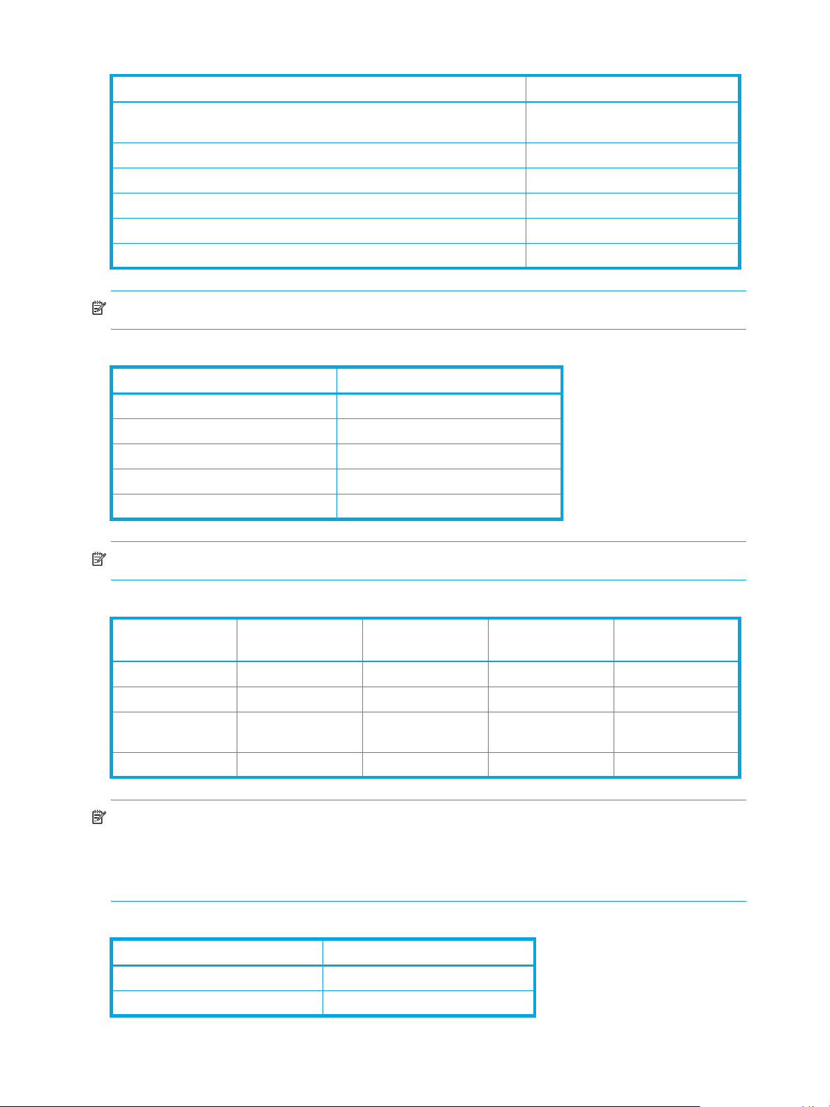
Table 17 Management area capacity of mainframe volumes
Emulation type Management area capacity
3380-3, 3380-3A, 3380-3B, 3380 -3C, 3380 -K, 3380-KA, 3380-KB,
3380-KC, NF80-K, NF80-KA, NF80-KB, NF80-KC
3390-3, 3390-3R, 3390-3A, 3390-3B, 3390-3C 6
3390-9, 3390-9A, 3390-9B, 3390-9C 25
3390-M, 3390-MA, 3390-MB, 3390-MC 53
3390-L, 3390-LA, 3390-LB, 3390-LC 23
3380-F, NF80-F 22
7
NOTE: A mainframe volume’s management area capacity is expressed in cylinders.
Table 18 Management area capacity of open-system volumes
Emulation type Management area capacity
OPEN-V 0
OPEN-3 5,760
OPEN-8 19,440
OPEN-9 19,440
OPEN-E 13,680
NOTE: An open system volume’s management area capacity is expressed in kilobytes.
Table 19 Boundary value for RAID levels
Emulation type Boundary value
for RAID1 (2D+2D)
3380-xx 768 1,152 2,688 2,304
3390-xx 1,024 1,536 3,584 3,072
OPEN-xx (except for
OPEN-V)
OPEN-V 1,024 1,536 3,584 3,072
768 1,1 52 2,68 8 2,304
Boundary value
for RAID5 (3D+1P)
Boundary value
for RAID5 (7D+1P)
Boundary value
for RAID6 (6D+2P)
NOTE:
• The xx is a variable indicating one or more numbers or letters.
• Boundary values are expressed in kilobytes.
• Boundary values of external volumes are always one kilobyte, regardless of RAID levels.
Table 20 Capacity of slots
Emulation type Capacity of slot
3380-xx, NF80-xx 48
3390-xx 64
46 Volume Management for the XP10000/XP12000
Page 47
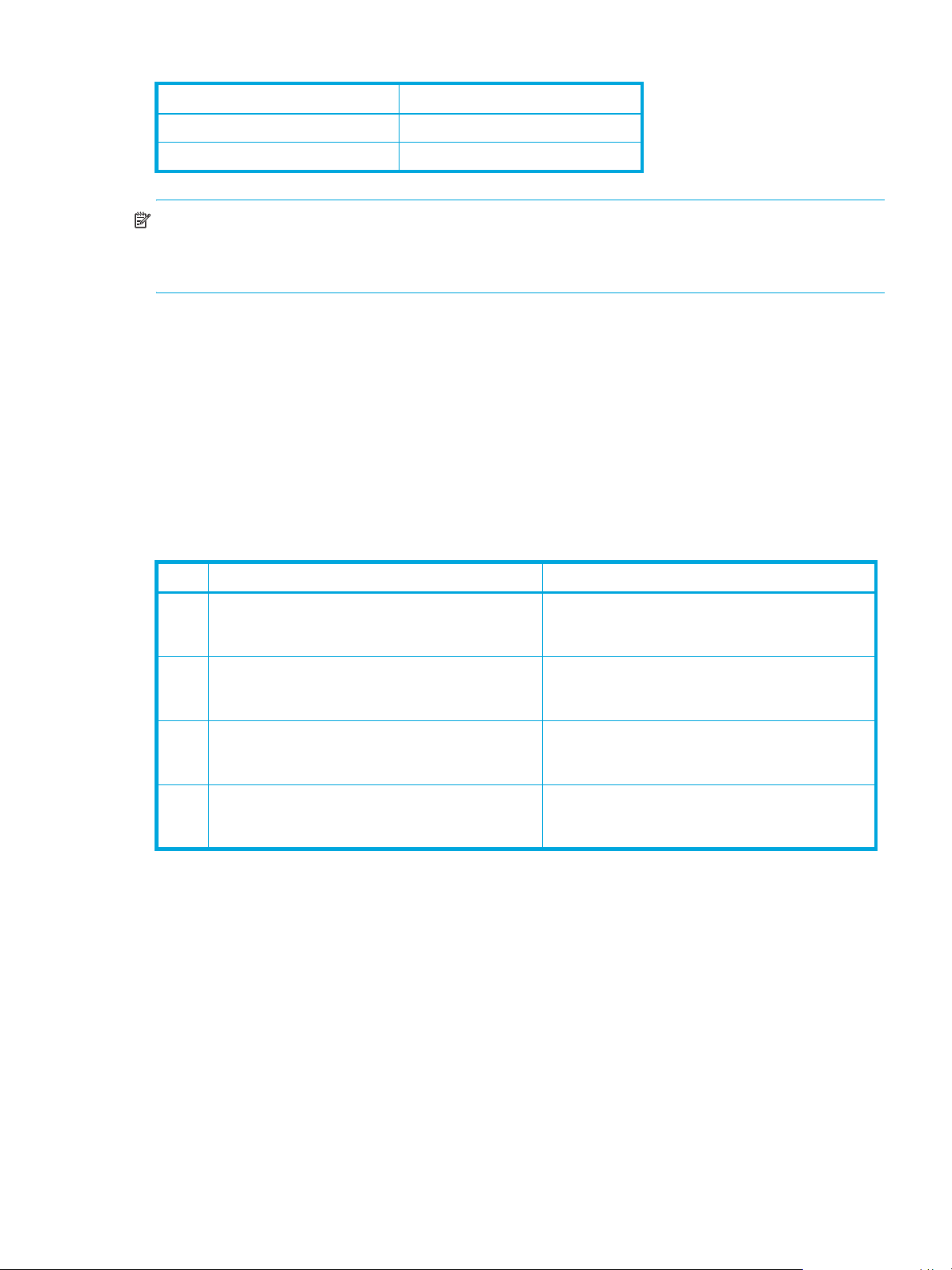
Table 20 Capacity of slots (continued)
Emulation type Capacity of slot
OPEN-xx (except for OPEN-V) 48
OPEN-V 256
NOTE:
• The xx is a variable indicating one or more numbers or letters.
• Slot capacity is expressed in kilobytes.
Volume Initialize and Make Volume operations
The Volume Initialize and the Make Volume functions reset a VDEV to its original configuration.
If you are not using OPEN-V, use the Volume Initialize function. The Volume Initialize function removes all
custom volume areas and free spaces on the VDEV and regenerates and formats initial fixed volumes. The
newly-formatted fixed volumes must be assigned CU and LDEV numbers. Existing fixed volumes on the
VDEV are not reformatted.
If you are using OPEN-V, use the Make Volume function. The Make Volume function deletes all volumes in
a VDEV, and creates new custom volumes according to the specified settings. Table 21 shows the
available settings.
Table 21 Settings for the Make Volume operation (OPEN-V only)
If the specified capacity exceeds 60 gigabytes (65,535 cylinders), the Make Volume function
automatically creates the VSC volume in LUSE configuration.
Restrictions
If the VDEV contains a custom volume that violates any of the restrictions, the Volume Initialize and Make
Volume functions are disabled. You must eliminate invalid custom volumes before performing the Volume
Initialize and Make Volume functions.
No. Specifies… VSC volumes to be created
1 The capacity and number of custom volumes under
a VSC volume.
2 The number of custom volumes. A VSC volume with the specified number of custom
3 The capacity of custom volumes. A VSC volume with custom volumes of the specified
4 The remaining capacity for a VSC volume. If some space remains in the VDEV after VSC
A VSC volume with the specified number of custom
volumes of the specified capacity is created. This is
the same as the Install CV operation.
volumes is created. The VDEV is divided by the
specified number.
capacity is created. The VDEV is divided by the
specified capacity.
volumes are created by settings 1 - 3, the remaining
space can be converted into a VSC volume.
• The LDEV must not have a path definition, including TrueCopy (TC390), Continuous Access XP,
ShadowImage (SI390), Business Copy (BC), and Continuous Access XP Journal pair volumes.
• The LDEV must not be a component of a LUSE volume (Volume Initialize only).
• The LDEV must not be reserved for Auto LUN.
• The access attribute must be set to Read/Write (Volume Initialize only).
• The CV must not be a pool volume (pool-VOL)
LUN Configuration and Security Manager XP user guide for the XP10000/XP12000 47
Page 48

LUSE operations
Users belonging to the Administrator and StorageAdmin groups can perform Modify VSC and Modify
LUSE operations.
Starting LUSE operations
1. Click the Volume Management button ( ). The Volume Management pane appears.
Figure 21 Volume Management pane
Volume Management pane
The Volume Management pane includes the following sections.
LDEV Information tree
The top of the pane shows a tree and list of CU numbers (CUxx) and LDEV numbers (xx:xx). When an
LDEV is made up of LUSE volumes, the top LUSE number is displayed with the number of members
preceded by an asterisk (*n). The number is the number of LDEVs that the LUSE volume contains, such as
00:02*2.
LDEV Information table
The status of each LDEV is indicated by one of the following icons.
Table 22 LDEV status icons for LUSE operations
Icon LDEV status
Normal LDEV
Custom volume
LUSE volume
When you select a CU in the LDEV Information tree, this table shows information about all LDEVs in the
CU. When you select an LDEV, the table shows detailed information about the LDEV. When you select a
LUSE volume, the table shows detailed information about all LDEVs in the LUSE volume.
48 Volume Management for the XP10000/XP12000
Page 49

The table contains the following information:
• LDEV: An LDEV status icon (Table 22), a CU number, and an LDEV number. If the selected LDEV is a
LUSE volume, the LDEV number of the top LDEV in the LUSE volume is displayed. An LDEV number that
ends with a # indicates that the LDEV is an external LU (for example, 00:01#).
NOTE: If an LDEV number ends with V (for example, 00:01V), the LDEV is a virtual volume
(V-VOL). For more information about V-VOLs, see the HP StorageWorks Snapshot XP User Guide.
• Emulation: The emulation type of the LDEV. If the selected LDEV is a VSC volume, the emulation type is
displayed together with CVS (for example, OPEN-3 CVS). If the selected LDEV is a LUSE volume, the
emulation type is displayed with an asterisk and the number of volumes in the LUSE volume (for
example, OPEN-E*5). If the LDEVs that comprise a LUSE volume extend over two or more VDEVs, the
emulation type is not displayed with an asterisk and the number of volumes (*n), and each LDEV in the
LUSE volume is displayed.
• Capacity: The capacity of the LDEV in either MB or GV, depending on which unit you selected in the
Capacity Unit box.
• RAID: The RAID level of the LDEV. The RAID level column contains a hyphen (-) when the LDEV is an
external LU or virtual volume (V-VOL).
• PG: A combination of a disk group and a parity group. If the LDEV extends over two or more parity
groups, the PG column displays the smaller parity group number. A parity group number that starts
with a letter E indicates that the parity group consists of one or more external LUs (for example, E1-1).
NOTE: If a parity group number starts with V (for example, V1-1), the parity group consists of one
or more virtual volumes (V-VOLs).
• Paths: The number of paths that is set for the LDEV. If this column displays the number of paths for an
LDEV, you can use the LDEV as the top LDEV of a LUSE volume. For more information, see ”LUSE
operations that handle a path-defined LDEV” on page 38.
• Access Attribute: The access attribute that is set for the LDEV
• IO Suppression: Displays Disable when the I/O request from the host is suppressed, or Enable if the
I/O request from the host is not suppressed
• Cache mode: Displays Disable when the cache is not set to be used for responding to the I/O request
from the host, or Enable when the cache is set to be used for responding to the I/O request from the
host
• Ex-Dev Info.: Displays the drive type of the LDEV. Displays an asterisk (*) when the drive type is SATA.
Nothing is displayed when the drive type is not SATA.
• CLPR: The ID of the CLPR (cache logical partition) to which the displayed volumes belong. The CLPR ID
is a CLPR number (two-digit) and a CLPR name (16 characters maximum)
• Selected LDEVs: The number of LDEVs selected in the LDEV Information table
• Capacity Unit button: Select a capacity unit (GB or MB) to describe LDEVs
Select an LDEV list
Displays the LDEVs, VSC volumes, and LUSE volumes of the selected CU that are eligible to become part of
a LUSE volume. The selected LDEV number becomes the top LDEV number of a LUSE volume.
NOTE: An LDEV selected in the LDEV Information Tree appears in the Select an LDEV list.
LUN Configuration and Security Manager XP user guide for the XP10000/XP12000 49
Page 50

Volume Count list
Specifies the number of LDEVs that should form a LUSE volume. For example, if you select 3 in the Volume
Count list, three LDEVs are expected to form a LUSE volume and then three LDEVs are added to the
Expanded LDEVs list. You can select an LDEV only from the Volume Count list. You cannot select a LUSE
volume.
Free LDEVs table
Lists the LDEVs, VSC volumes, and LUSE volumes that can constitute a LUSE volume in combination with the
LDEV selected as a top LDEV in the Select an LDEV list. The table contains the following information:
• LDEV: An LDEV status icon (Table 22), a CU number, and an LDEV number. If the selected LDEV is a
LUSE volume, the LDEV number of the top LDEV in the LUSE volume is displayed. An LDEV number that
ends with a # indicates that the LDEV is an external LU (for example, 00:01#).
NOTE: If an LDEV number ends with V (for example, 00:01V), the LDEV is a virtual volume
(V-VOL). For more information about V-VOLs, see the HP StorageWorks Snapshot XP User Guide.
• Capacity: Capacity of the LDEV represented in units (GB or MB), based on the capacity you indicate
with the Capacity Unit box.
• RAID: RAID level of the LDEV. The RAID level column contains a hyphen (-) when the LDEV is an external
LU or virtual volume (V-VOL).
• PG: A combination of the disk group and the parity group. If the LDEV extends over two or more parity
groups, the PG column displays the smaller parity group number. A parity group number that starts
with a letter E indicates that the parity group consists of one or more external LUs (for example, E1-1).
NOTE: If a parity group number starts with V (for example, V1-1), the parity group consists of one
or more virtual volumes (V-VOLs).
• CLPR: The cache logical partition (CLPR) number and name. The CLPR number consists of two digits.
The CLPR name consists of up to six characters. For detailed information about CLPRs, see the
HP StorageWorks XP Disk/Cache Partition User Guide.
• Selected LDEVs: The number of LDEVs selected in the Free LDEVs table
Expanded LDEVs list
Lists the LDEVs that are selected as LUSE volume components. An LDEV from the Free LDEVs table is added
to this list by clicking Add. The Expanded LDEVs list contains the following information:
• Selected LDEVs: Number of LDEVs selected in the Expanded LDEVs list
• Number of LDEVs: Number of LDEVs contained in a LUSE volume
• Capacity: The capacity of a LUSE volume. The number is displayed in GB or MB depending on the
selected capacity unit.
Buttons
• Add: Adds the selected LDEVs from the Free LDEVs table to the Expanded LDEVs list
• Delete: Removes the selected LDEVs from the Expanded LDEVs list and moves it back to the Free LDEVs
table
• Set: Creates a LUSE volume consisting of the volumes in the Expanded LDEVs list. The LDEVs that are
set as LUSE volume components are shown in blue in the LDEV Information table and the free LDEVs are
deleted from the table.
• Apply: Registers the LUSE settings with the disk array
• Cancel: Cancels the LUSE settings
50 Volume Management for the XP10000/XP12000
Page 51

Viewing LUSE configuration information
• The LDEV Information tree displays an outline view of the CU and LDEV numbers installed on the disk
array in a hierarchical structure.
• The LDEV Information table displays detailed information for all open system LDEVs in the selected CU.
If you select a normal LDEV, the information in this section is for the top LDEV. If you select a LUSE
volume, the information in this table is for all of the LDEVs in the LUSE volume.
An LDEV number that ends with a # indicates that the LDEV is an external LU (for example, 00:01#).
Viewing concatenated parity groups
1. From the Volume Management pane, select a CU number in the LDEV Information tree. The LDEV
Information table displays all the LDEVs in the selected CU.
2. In the LDEV Information table, select the free LDEVs for the LUSE volume and right-click. If the parity
groups are concatenated, the Concatenation List command is available in the shortcut menu.
3. Select Concatenation List. The Concatenation List dialog box appears.
4. Click OK to return to the Volume Management pane.
Creating a LUSE volume using the Volume Count list
CAUTION: Creating a LUSE volume destroys existing data. To protect your data, make a backup copy of
the existing data before starting the LUSE creation operation.
1. From the Volume Management pane, select a CU number in the LDEV Information tree.
2. In the Select an LDEV list, select a top LDEV of the LUSE volume. The Expanded LDEVs list displays the
selected volume. The Free LDEVs table displays normal LDEVs, allocated LDEVs, VSC volumes, and
LUSE volumes that can be used for a LUSE volume.
If you select a LUSE volume as the top LDEV, the Volume Count list is unavailable, and step 3 cannot be
performed. In this case, select the LDEVs in the Free LDEVs table and click Add. To delete LDEVs, select
the LDEVs in the Expanded LDEVs list and click Delete.
3. In the Volume Count list, select the number of LDEVs that should form a LUSE volume.
The Expanded LDEVs list displays as many LDEVs as specified in the Volume Count list. For example, if
3 is specified, the Expanded LDEVs list displays three LDEVs.
NOTE: You cannot select the LUSE volumes in the Volume Count list. To select LUSE volumes, select
the LDEVs in the Free LDEVs table and click Add.
• To add more LDEVs to the Expanded LDEVs list, select one or more LDEVs in the Free LDEVs table
and click Add.
• To delete LDEVs from the Expanded LDEVs list, select one or more LDEVs in the Expanded LDEVs list
and click Delete.
4. Click Set. A confirmation message appears.
• If you are performing a LUSE operation on a path-defined volume, a confirmation message
appears. Click OK to confirm. Another confirmation message appears. Go to step 5.
• If you are performing a LUSE operation on a volume that does not have a path definition, a
confirmation message appears.
5. To create a LUSE volume, click OK. The changes are shown in blue in the LDEV Information table.
6. Click Apply. A confirmation message appears.
7. Click OK. The LUSE settings are registered with the disk array. A dialog box appears when the
requested action is complete.
8. Click OK.
LUN Configuration and Security Manager XP user guide for the XP10000/XP12000 51
Page 52

Creating a LUSE volume using the Select an LDEV list
CAUTION: Creating a LUSE volume destroys existing data. To protect your data, make a backup copy of
the existing data before starting the LUSE creation operation.
1. In the Volume Management pane, select a CU number in the LDEV Information tree.
2. In the Select an LDEV list, select a top LDEV of the LUSE volume. The Expanded LDEVs list displays the
selected volume. The Free LDEVs table displays normal LDEVs, allocated LDEVs, VSC volumes, and
LUSE volumes that can be used for a LUSE volume.
• To add LDEVs to the Expanded LDEVs list, select one or more LDEVs in the Free LDEVs table and
click Add. The selected LDEVs are added to the Expanded LDEVs list and deleted from the Free
LDEVs table.
• To delete LDEVs from the Expanded LDEVs list, select one or more LDEVs in the Expanded LDEVs list
and click Delete. The selected LDEVs are deleted from the Expanded LDEVs list and displayed in the
Free LDEVs table.
3. Click Set. A confirmation message appears.
4. To perform a LUSE operation on a volume that has a path definition, click OK. If a message appears
asking if you want to perform a LUSE operation that will affect more than one SLPR or CLPR, go to
step 5. Otherwise, go to step 6.
5. To perform a LUSE operation that will affect more than one SLPR or CLPR, click OK. A confirmation
message appears.
6. Click OK. The changes are shown in blue in the LDEV Information table.
7. Click Apply. A confirmation message appears.
8. Click OK. The LUSE settings are registered with the disk array. A dialog box appears when the
requested action is complete.
9. Click OK.
Creating a LUSE volume using the LDEV information table
CAUTION: Creating a LUSE volume destroys existing data. To protect your data, make a backup copy of
the existing data before starting the LUSE creation operation.
1. In the Volume Management pane, select a CU number in the LDEV Information tree.
2. In the LDEV Information table, select the normal LDEVs, VSC volumes, or LUSE volumes. Right-click the
selection and select Set LUSE Volume.
a. To perform a LUSE operation on a volume that has a path definition, click OK. If a message
appears asking if you want to perform a LUSE operation that will affect more than one SLPR or
CLPR, go to step 2. Otherwise, go to step 3.
b. To perform a LUSE operation on a volume that will affect more than one SLPR or CLPR, click OK. A
confirmation message appears.
3. Verify the information in the dialog box and click OK. The LUSE creation starts. The changes are shown
in blue in the LDEV Information table.
4. Click Apply. A confirmation message appears.
5. Click OK. The LUSE setting is registered. A dialog box appears when the requested action is complete.
6. Click OK.
Releasing a LUSE volume
CAUTION: This operation destroys data. To protect data, be sure to make a backup copy before starting
the LUSE releasing operation.
52 Volume Management for the XP10000/XP12000
Page 53

1. In the Volume Management pane, select the CU number from which you want to release a LUSE
volume. The LDEV Information table shows all LDEVs that the selected CU contains.
2. In the LDEV Information table, right-click the desired LUSE volume and select Release LUSE Volume. A
LUSE release confirmation message appears.
3. Verify that the information is correct and click OK. The LUSE release starts. The changes are shown in
blue in the LDEV Information table.
4. Click Apply. A confirmation message appears.
5. Click OK. The LUSE volume is released. A dialog box appears when the requested action is complete.
6. Click OK.
Changing LUSE capacities
• Expanding LUSE capacities
To expand the capacity of a LUSE volume, select the LUSE volume you want to expand, and then add
LDEVs or LUSE volumes, or first select the LDEVs or LUSE volumes you want to add, and then select a
LUSE volume to be expanded. For more information, see ”Creating a LUSE volume using the Volume
Count list” on page 51, ”Creating a LUSE volume using the Select an LDEV list” on page 52, or
”Creating a LUSE volume using the LDEV information table” on page 52.
Each LDEV or LUSE volume that you want to add must have the same capacity as each LDEV in a LUSE
volume to be expanded.
• Reducing LUSE capacities
You may not reduce the capacity of an existing LUSE volume. If you want a LUSE volume to have a
smaller capacity, you must release and then redefine the LUSE volume.
Resetting an unregistered LUSE volume
When you create a LUSE volume, the screen shows the changes in blue bold italics until you register the
volume into the disk array by clicking Apply. The LUSE volume in blue bold italics indicates that you can
reset this LUSE volume to the state before it was created.
If the XP disk array has firmware version 21.06.22 or later installed, you can reset an unregistered LUSE
volume to the state before it was created. However, you cannot recover any LUSE volumes that have been
released already to the state when they were created. If the LUSE volume that you have created consists of
any LDEVs (those in blue bold italics) that have once been released from a different LUSE volume, you can
only reset your LUSE volume to the state when the constituting LDEVs were released from the other LUSE
volume.
1. In the Volume Management pane, select the CU number from which you want to reset an unregistered
LUSE volume. The LDEV Information table shows all LDEVs that the selected CU contains.
2. In the LDEV Information table, right-click an unregistered LUSE volume (displayed in blue bold italics)
and select Reset Selected Volume. A confirmation message appears.
3. Verify the information in the dialog box and click OK. The unregistered LUSE volume will be reset to the
state before this LUSE volume was created. The LDEV Information table displays the LUSE volumes or the
LDEVs constituting the selected LUSE volume that has just been reset.
VSC Operations
Before beginning VSC operations, put the volumes in an offline state or unmount them (deallocate LUN
paths).
Users belonging to the Administrator and StorageAdmin groups can perform VSC operations.
Starting VSC operations
1. Click the Volume Management button ( ). The Volume Management pane appears.
LUN Configuration and Security Manager XP user guide for the XP10000/XP12000 53
Page 54

2. Click the Customized Volume tab. The Customized Volume pane appears.
Figure 22 Customized Volume pane (Volume Management screen)
Customized Volume pane
Parity Group - LDEV tree
This tree shows a hierarchical structure of a disk group number (Box 1), parity group numbers (for
example, 1-1), RAID levels (for example, 3D+1P), and VDEV numbers (for example, 1-1-1).
If a parity group number starts with V (for example, V1-1), the parity group consists of one or more virtual
volumes.
If an LDEV number ends with # (for example, 00:01#) the LDEV is an external LU.
The RAID level is left unspecified with a hyphen (-) when the LDEV is an external LU.
The status of each parity group is indicated by one of the following icons.
Table 23 Parity group status icons
Icon Status
Parity group
A set of parity groups that are concatenated into one. Each LDEV in this set of parity groups usually
extends over more than one parity group.
The status of each VDEV is indicated by one of the following icons.
Table 24 VDEV status icons
Icon Status
No pending VSC actions
VSC actions have been stored, but not yet implemented on the subsystem
Parity Group - LDEV table
This table shows information about volumes in a VDEV selected in the Parity Group - LDEV tree.
54 Volume Management for the XP10000/XP12000
Page 55

The status of each LDEV is indicated by one of the following icons.
Table 25 LDEV status icons for VSC operations
Icon Status
Normal LDEV
LUSE volume
LDEV reserved for Auto LUN
VSC volume
VSC volume reserved for Auto LUN
Free space
The table contains the following information:
• No.: The number of a volume in the VDEV
• CU:LDEV: A CU number/LDEV number combination. Free indicates a free space. If an LDEV number
ends with # (for example, 00:01#), the LDEV is an external LU. If an LDEV number ends with V (for
example, 00:00V), the LDEV is a virtual volume. For more information about virtual volumes, see the
HP StorageWorks Snapshot XP User Guide.
• Emulation: Emulation type of the volume
• Capacity: Capacity of the volume represented in the selected unit (MB, Cyl, or block)
• Paths: Number of LU paths that the volume has. This box is blank when the volume has no LU paths.
• Access Attribute: Access attribute of the volume
• Status: Status of the volume. You must click LDEV Status to display the volume status. Table 26 describes
the volume status displayed in the Status column.
Table 26 Volume status
Status Description
Normal Volume is in a normal status.
Blocked Volume is in a blocked status. Hosts cannot access the blocked volume.
Warning Volume has a problem.
Format Volume is being formatted.
Correction Access Volume’s access attribute is being changed.
Copying Volume’s data is being copied.
Read Only Hosts can only read the volume. Hosts cannot write any data to the volume.
Shredding The Shredding operation is in progress.
Unknown System does not recognize the volume’s status.
Capacity unit list
The Capacity Unit list allows you to select the unit (MB, Cyl, or block) to display for volume capacity.
When you manipulate mainframe volumes, you can only select Cyl.
Buttons
• Apply: Registers the VSC settings
• Cancel: Cancels the VSC settings
• LDEV Status: Displays the current volume status
LUN Configuration and Security Manager XP user guide for the XP10000/XP12000 55
Page 56

• Shredding Param: Displays the Shredding Param (Parameter) pane where you can define shredding
settings.
• Download: Downloads the file containing the results of Shredding operations.
NOTE: Currently, the Shredding Param and Download buttons are not supported.
Viewing VSC configuration information
Use the Customized Volume pane and its associated panes to view the current VSC configuration
information:
• View the VDEV and LDEV configuration information on the Customized Volume pane. This pane shows
an outline of group numbers, parity group numbers, RAID levels, and VDEV numbers and a table of
CU:LDEV numbers, emulation types, LDEV capacities, and path settings of VDEVs selected in the
outline.
• View the LDEV number setting information from the Install CV, Make Volume, and Volume Initialize
panes. In the table, gray indicates LDEV numbers that are already in use, white indicates unused LDEV
numbers, and blue indicates available LDEV numbers.
Viewing concatenated parity groups
1. In the Customized Volume pane, select a set of parity groups from the Parity Group - LDEV tree and
right-click. If the parity groups are concatenated, the Concatenation List command is available in the
shortcut menu.
2. Select Concatenation List. The Concatenation List dialog box appears.
3. Click OK.
Converting volumes to space (Volume to Space)
Use the Volume to Space function to convert logical volumes to space (free areas).
CAUTION: The Volume to Space operation destroys data on the logical volumes that are converted.
1. From the Customized Volume pane, select a disk group, a parity group, and a VDEV in the Parity
Group - LDEV tree. The Parity Group - LDEV table displays information about LDEVs in the selected
VDEV.
2. Select one or more LDEVs (normal or custom volumes) you want to convert to space.
For the OPEN-V emulation type, LUSE volumes can also be converted into free space. If the available
LDEV is a LUSE volume, the emulation type is displayed together with an asterisk and the number of
volumes in the LUSE volume (for example, OPEN-V*3) in the Emulation column of the table.
To select two or more consecutive LDEVs, click the LDEVs while pressing the Shift key. To select two or
more non-consecutive LDEVs, click the LDEVs while pressing the Ctrl key.
NOTE: You cannot change all LDEVs in the selected VDEV into space. You cannot select the last
normal or custom volume.
3. Right-click the selected LDEV and select Volume to Space. A volume confirmation dialog box is
displayed.
4. Click OK. The Parity Group - LDEV table is displayed and the selected LDEVs are marked Free. The
figures in the Capacity column are not yet updated, and the color of the VDEV icon that you
manipulated changes from red to blue. You cannot manipulate blue VDEVs until you click Apply or
Cancel.
5. Click Apply. A confirmation message appears.
6. Click OK. The LDEVs are converted to space. A dialog box appears when the requested action is
complete.
56 Volume Management for the XP10000/XP12000
Page 57

7. Click OK.
Creating custom volumes (Install CV)
Use the Install CV function to create and install one or more custom volumes in the free space that is
prepared by the Volume to Space function. The Install CV function can define (install) one or more new
custom volumes in the free space prepared when volumes are created in VDEVs.
1. In the Customized Volume pane, click the LDEV folder in the Parity Group - LDEV tree to open a list of
CUs, and then select a VDEV. The Parity Group - LDEV table displays information about LDEVs in the
selected VDEV.
2. Right-click any part of the Parity Group - LDEV tree and select Install CV.
If the selected VDEV is an OPEN-V volume, the Install CV pane (1) for OPEN-V appears (Figure 23).
Go to step 3.
If the VDEV you selected is not an OPEN-V volume, the Install CV pane (1) for non-OPEN-V appears
(Figure 24). Go to step 4.
Figure 23 Install CV pane (1) for OPEN-V (when two or more free spaces are available)
LUN Configuration and Security Manager XP user guide for the XP10000/XP12000 57
Page 58
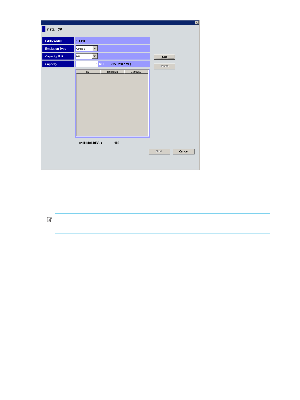
Figure 24 Install CV pane (1) for other than OPEN-V
3. From the Install CV pane (1) for OPEN-V, do the following:
a. In the Capacity Unit area, select MB, Cyl, or block for the capacity unit.
b. Select one of methods by clicking Specify capacity and number, Divide free space by number,
Divide free space by capacity, or Set remaining space as volume.
NOTE: If there are two or more free spaces in the VDEV, only the Specify capacity and number
option is available.
c. Specify the capacity of the volume and/or the number of volumes according to the selected
method. For example:
•If you selected Specify capacity and number, enter the capacity, either in MB, Cyl, or blocks, in
the Capacity box and the number of custom volumes in the Number box.
•If you selected Divide free space by number, enter the number of custom volumes in the Number
box.
•If you selected Divide free space by capacity, enter the capacity in the Capacity box.
•If you selected Set remaining space as volume, go to step 3d.
The Install CV Volume function allocates custom volumes in the order in which the function finds
sufficient free space for the custom volumes, so for optimum space allocation you should allocate
custom volumes in descending order of capacity.
58 Volume Management for the XP10000/XP12000
Page 59

d. Click Set. The pane displays the selected custom volumes.
Figure 25 Install CV pane (1) for OPEN-V after clicking Set
e. To create other custom volumes, repeat step 3a through step 3d.
f. To delete a custom volume, select the custom volume, click Delete, and then click OK to the
confirmation message. To delete all custom volumes, click Clear, and then click OK. Go to step 5.
4. From the Install CV pane (1) for other than OPEN-V, do the following:
a. In the Emulation Type list, select the emulation type.
b. In the Capacity box, enter the capacity of the custom volume you want to create. Use MB or blocks
for open systems and cylinders (Cyl) for mainframe volumes. The available capacity range
(minimum - maximum) appears to the right of the Capacity box. The value can be increased
incrementally by one MB or block (open systems) or by one cylinder (mainframe systems).
The Install CV function allocates custom volumes in the order in which the function finds free space
sufficient enough to hold them. Allocate custom volumes in descending order of capacity for
optimum space allocation.
LUN Configuration and Security Manager XP user guide for the XP10000/XP12000 59
Page 60

c. Click Set. The pane displays the selected custom volumes.
Figure 26 Install CV pane (1) for other than OPEN-V after clicking Set
d. Repeat step 4a through step 4c to create additional custom volumes.
e. To delete a custom volume, click the custom volume, click Delete, and then click OK.
5. After configuring custom volumes, click Next. The Install CV pane (2) is displayed.
Figure 27 Install CV pane (2)
60 Volume Management for the XP10000/XP12000
Page 61
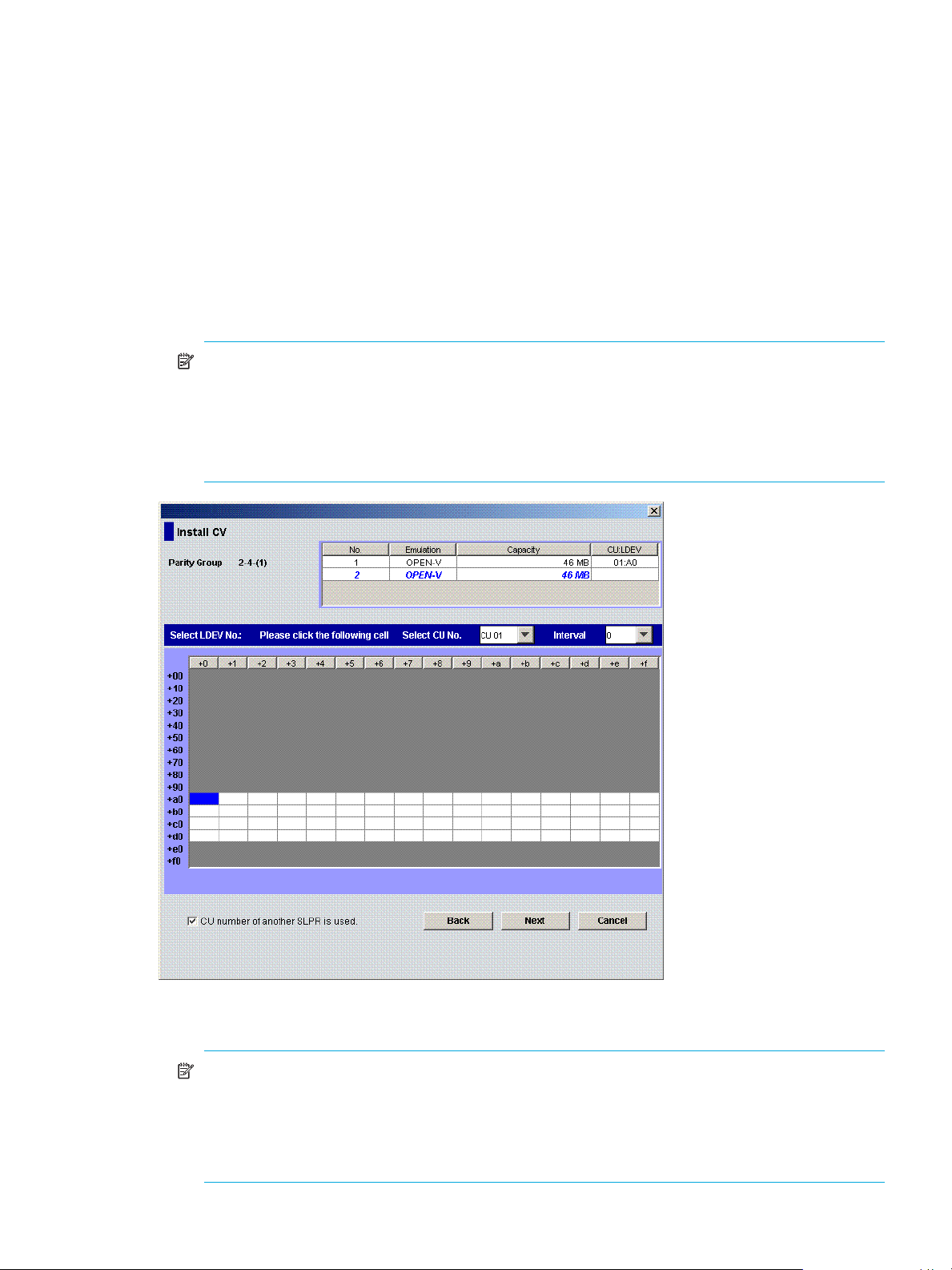
Use this pane to assign the CU and LDEV numbers of a custom volume to be created. The top area is
the CV setting information area and shows detailed information about the custom volumes to be
created. The bottom area is the LDEV number setting area and is used to set the CU and LDEV numbers
for the custom volume to be created.
6. In the CV setting information area, select one or more custom volumes.
7. In the Select CU No. list, select a CU number. The LDEV number setting area is updated to reflect the
selected CU number.
8. If you selected multiple custom volumes, select an interval from the Interval list. This value specifies the
interval between the LDEV numbers that need to be assigned to the new volumes. The default value is
0. When you select 0, consecutive LDEV numbers are assigned. The value you specify as the interval
between LDEV numbers counts only the available LDEV numbers.
9. In the LDEV number setting area, select an LDEV number by clicking the appropriate white box. For
example, to select an LDEV number of 96, click the +90/+6 box as shown in Figure 28.
NOTE: The CU number of another SLPR is used check box is displayed only when you logged in
as a user in the StorageAdmin group with full array access and when there are two or more SLPRs.
When the CU number of another SLPR is used check box is selected, you can select the number of
an LDEV that does not exist in an SLPR to which the priority group does not belong. When the check
box is cleared, you can only select the number of an LDEV in the SLPR to which the parity group
belongs.
Figure 28 Select an LDEV number
The CU:LDEV number in the CV setting information area is updated.
NOTE: If you specify an LDEV number in the selected CU, free sequential LDEV numbers in LUSE
configuration are automatically assigned. You cannot specify an LDEV number, if free LDEV
numbers in LUSE configuration are not available in either of the following CUs:
• The CU displayed in the Select CU No. list.
• A CU whose CU number is larger than the CU number displayed in the Select CU No. list.
LUN Configuration and Security Manager XP user guide for the XP10000/XP12000 61
Page 62

10.Repeat step 6 - step 9 to set additional custom volumes.
11.To change a set volume, right-click the volume in the CV setting information area, and select Clear.
12.After setting all CU and LDEV numbers, click Next.
If the boundary area of the selected LDEV number does not have an SSID, a dialog box is displayed for
setting the SSID (Figure 29). Go to step 13.
Figure 29 Setting the SSID
If the boundary area of the selected LDEV number has an SSID, go to step 15.
13.In the SSID setting area, select a CU number to assign an SSID to, enter a new SSID in the Input SSID
box, and click Set. The SSID is displayed in the SSID box of the SSID setting area. Repeat this step until
all the SSIDs are set.
NOTE: You can enter the SSID only when logged in as a user in the StorageAdmin group with full
array access.
NOTE: The SSID of another SLPR is used check box is displayed only when you logged in as a
user in the StorageAdmin group with full array access and when there are two or more SLPRs.
When the SSID of another SLPR is used check box is selected, you can select the number of an SSID
that does not exist in an SLPR to which the parity group does not belong. When the check box is
cleared, you can only select the number of the SSID in the SLPR to which the parity group belongs.
You cannot enter the number in the Input SSID box when the SSID number of another SLPR is used
check box is cleared.
14.After setting all the SSIDs, click Next. The Install CV confirmation dialog box is displayed.
62 Volume Management for the XP10000/XP12000
Page 63

15.Verify that the information in the Install CV confirmation dialog box is correct, and click OK. The
Customized Volume screen is displayed with the new settings in blue.
Figure 30 Customized volume screen
16.Click Apply. A confirmation message appears.
17. Click OK. The custom volume is created. A dialog box appears when the requested action is complete.
18.Click OK.
Deleting custom volumes (Volume to Space)
To delete a custom volume from a VDEV, convert the custom volume into free space with the Volume to
Space function (see ”Converting volumes to space (Volume to Space)” on page 56).
Creating initial custom volumes for OPEN-V (Make Volume)
Use the Make Volume function to clear all custom volumes under a VSC volume and create an initial
volume (VDEV) that consists of new user-defined custom volumes.
CAUTION:
• The Make Volume function is a destructive operation and destroys the data on selected custom volumes.
Back up the data as needed before performing this operation.
• An error message might appear if Volume Initialize and Make Volume operations are performed
concurrently. For this error message, the part code is 0003 and the error number is 1041. If this
message appears, ensure that these operations are performed separately.
1. From the Customized Volume pane, click the LDEV folder in the Parity Group - LDEV tree to open a list
of CUs, and then select a VDEV. The Parity Group - LDEV table displays information of LDEVs in the
selected VDEV.
NOTE: If the selected VDEV contains one or more custom volumes that violates any restriction for
the Make Volume function (see ”Volume to Space operation” on page 41), you cannot perform the
Make Volume function. Remove all invalid custom volumes before performing the Make Volume
function.
LUN Configuration and Security Manager XP user guide for the XP10000/XP12000 63
Page 64
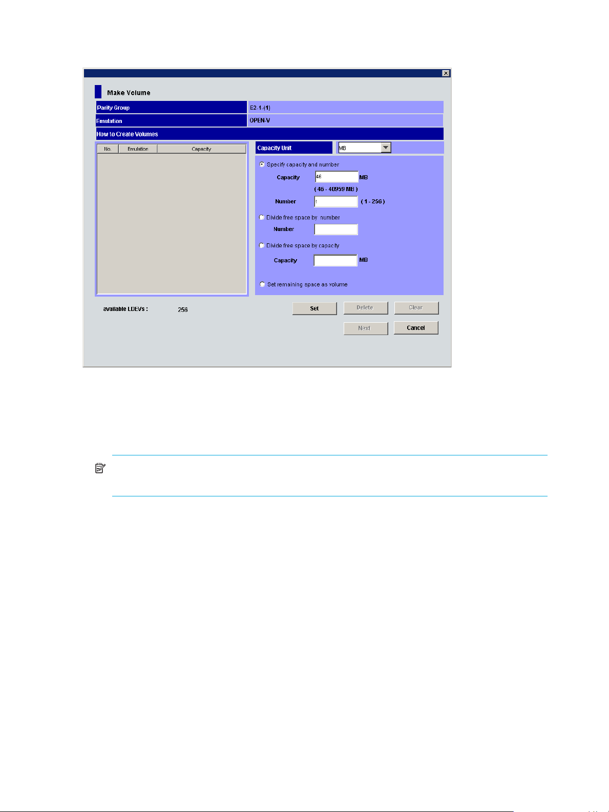
2. Right-click any part of the Parity Group - LDEV tree and select Make Volume. The Make Volume pane
(1) appears.
Figure 31 Make Volume pane (1)
3. From the Make Volume pane (1), do the following:
a. In the Capacity Unit list, select MB, Cyl, or block for the capacity unit.
b. Select one of methods by clicking Specify capacity and number, Divide free space by number,
Divide free space by capacity, or Set remaining space as volume.
NOTE: If there are two or more free spaces in the VDEV, only the Specify capacity and number
option is available.
c. Specify the capacity of the custom volume and/or the number of custom volumes according to the
selected method. For example:
•If you selected Specify capacity and number, enter the capacity, in MB, Cyl, or blocks, in the
Capacity box and the number of custom volumes in the Number box.
•If you selected Divide free space by number, enter the number of custom volumes in the Number
box.
•If you selected Divide free space by capacity, enter the capacity in the Capacity box.
•If you selected Set remaining space as volume, go to the next step.
64 Volume Management for the XP10000/XP12000
Page 65

d. Click Set. The pane displays the setting in the table.
Figure 32 Make Volume pane (1) after clicking Set
e. To set other custom volumes, repeat step 3a through step 3d.
f. To remove a setting, select the custom volume, click Delete, and then click OK. To remove all
settings, click Clear, and then click OK.
4. After setting all custom volumes, click Next. The Make Volume pane (2) appears.
LUN Configuration and Security Manager XP user guide for the XP10000/XP12000 65
Page 66

NOTE: If no CV is set, the Make Volume operation does not create a volume in the VDEV. In this
case, a message appears and the Volume Management pane appears.
Figure 33 Make Volume pane (2)
Use this pane to assign CU and LDEV numbers to the custom volumes to be created. The top area is the
CV setting information area and shows detailed information about the custom volumes to be initialized.
The bottom area is the LDEV number setting area and is used to set the CU and LDEV numbers for the
custom volume to be initialized.
5. In the CV setting information area, select one or more custom volumes.
6. In the Select CU No. list, select a CU number.
7. If you selected multiple custom volumes, select an interval from the Interval list. This value specifies the
interval between the LDEV numbers that need to be assigned to the new volumes. The default value is
0. When you select 0, consecutive LDEV numbers are assigned. The value you specify as the interval
between LDEV numbers counts only the available LDEV numbers.
8. In the LDEV number setting area, select an LDEV number by clicking the appropriate white box. For
example, to select an LDEV number of 97, click the +90/+7 box as shown in Figure 34.
66 Volume Management for the XP10000/XP12000
Page 67

NOTE: The CU number of another SLPR is used check box is displayed only when you logged in
as a user in the StorageAdmin group with full array access and when there are two or more SLPRs.
When the CU number of another SLPR is used check box is selected, you can select the number of
an LDEV that does not exist in an SLPR to which the parity group does not belong. When the check
box is cleared, you can only select the number of an LDEV in an SLPR to which the parity group
belongs.
Figure 34 Select an LDEV number
The CU:LDEV number in the CV setting information area is updated.
NOTE: If you specify an LDEV number in the selected CU, free sequential LDEV numbers in LUSE
configuration are automatically assigned. You cannot specify an LDEV number if free LDEV numbers
in LUSE configuration are not available in either of the following CUs:
• The CU displayed in the Select CU No. list.
• A CU whose CU number is larger than the CU number displayed in the Select CU No. list.
9. Repeat step 5 - step 8 to set additional volumes.
10.To change a set volume, right-click the volume and select Clear from the shortcut menu.
11.After setting all CU and LDEV numbers, click Next.
If the boundary area of the selected LDEV number does not have an SSID, a dialog box is displayed for
setting the SSID. Go to step 12.
If the boundary area of the selected LDEV number has an SSID, the Make Volume confirmation dialog
box is displayed. Go to step 14.
12.In the SSID setting area, select a CU number to assign an SSID to it, enter a new SSID in the Input SSID
box, and click Set. The SSID is displayed in the SSID box of the SSID setting area. Repeat this step until
all the SSIDs are set.
13.After setting all the SSIDs, click Next. The Make Volume confirmation pane is displayed.
LUN Configuration and Security Manager XP user guide for the XP10000/XP12000 67
Page 68

14.Verify that the information is correct and click OK. The Customized Volume pane is displayed. The
created custom volumes are shown in blue.
NOTE: You cannot manipulate the VDEVs denoted by blue icons until you apply the changes to
the disk array or cancel them, but you can initialize additional custom volumes in VDEVs denoted
by red icons.
15.Click Apply. A confirmation message appears.
16.Click OK. The Make Volume operation begins. When LDEV formatting is in progress and at
completion, a notation is displayed across the bottom of the screen to indicate the progress. A dialog
box is displayed when the requested action is complete.
17. Click OK.
Initializing custom volumes for other than OPEN-V (Volume Initialize)
Use the Volume Initialize function to uninstall all custom volumes under a VSC volume, and reformat the
VSC volume as a normal volume (VDEV).
CAUTION:
• The Volume Initialize function is a destructive operation and destroys the data on selected custom
volumes. Back up the data as needed before performing this operation.
• An error message might appear if Volume Initialize and Make Volume operations are performed
concurrently. For this error message, the part code is 0003 and the error number is 1041. If this
message displays, ensure that these operations are performed separately.
1. From the Customized Volume pane, click the LDEV folder in the Parity Group - LDEV tree to open a list
of CUs, and then select a VDEV. The Parity Group - LDEV table displays information about the LDEVs in
the selected VDEV.
NOTE: If the selected VDEV contains one or more custom volumes that violates any restriction for
the Volume Initialize function (see ”Volume to Space operation” on page 41), you cannot perform
the Volume Initialize function. Remove all invalid custom volumes before performing the Volume
Initialize function.
68 Volume Management for the XP10000/XP12000
Page 69

2. Right-click any part of the Parity Group - LDEV tree and select Volume Initialize. The Volume Initialize
pane is displayed.
Figure 35 Volume Initialize pane
Use this pane to initialize custom volumes other than OPEN-V. The top area is the CV setting
information area and shows detailed information about the custom volumes to be initialized. The
bottom area is the LDEV number setting area and is used to set the CU and LDEV numbers for the
custom volume to be initialized.
3. In the CV setting information area at the top of the pane, select one or more custom volume numbers.
4. In the Select CU No. list, select a CU number. The LDEV number setting area is updated to reflect the
selected CU number.
5. In the LDEV number setting area, select an LDEV number by clicking the appropriate white box. For
example, to select an LDEV number of 16, click the +10/+6 box as shown in Figure 36.
LUN Configuration and Security Manager XP user guide for the XP10000/XP12000 69
Page 70

NOTE: The CU number of another SLPR is used check box is displayed only when you logged in
as a user in the StorageAdmin group with full array access and when there are two or more SLPRs.
When the CU number of another SLPR is used check box is selected, you can select the number of
an LDEV that does not exist in an SLPR to which the parity group does not belong. When the check
box is cleared, you can only select the number of an LDEV in an SLPR to which the parity group
belongs.
Figure 36 Select an LDEV number
The CU:LDEV number in the CV setting information area is updated.
6. To set additional volumes, repeat step 3 - step 5.
7. To change a set volume, right-click the volume and select Clear from the shortcut menu.
8. After setting all CU and LDEV numbers, click Next.
If the boundary area of the selected LDEV number does not have an SSID, a dialog box is displayed for
setting the SSID. Go to step 9.
If the boundary area of the selected LDEV number has an SSID, the Volume Initialize confirmation
dialog box is displayed. Go to step 11.
9. In the SSID setting area, click a CU number to assign an SSID to it, select or enter a new SSID in the
Input SSID box, and click Set. The SSID is displayed in the SSID box of the SSID setting area. Repeat
this step until all the SSIDs are set.
NOTE: You can enter the SSID in the Input SSID box only when logged in as a user in the
StorageAdmin group with full array access.
70 Volume Management for the XP10000/XP12000
Page 71

NOTE: The SSID of another SLPR is used check box is displayed only when you logged in as a
user in the StorageAdmin group with full array access and when there are two or more SLPRs.
When the SSID of another SLPR is used check box is selected, you can select the number of an SSID
that does not exist in an SLPR to which the parity group does not belong. When the check box is
cleared, you can only select the number of the SSID in the SLPR to which the parity group belongs.
You cannot enter the number in the Input SSID box when the SSID number of another SLPR is used
check box is cleared.
10.After setting all the SSIDs, click Next. The Volume Initialize confirmation pane is displayed.
11.Verify that the information in the Volume Initialize pane is correct and click OK. The Customized Volume
pane is displayed.
A notation is displayed across the top of the screen to indicate that the volume has been initialized,
and the color of the VDEV icon that you manipulated in the Parity Group - LDEV outline view changes
from red to blue.
NOTE: You cannot manipulate VDEVs with blue icons until you apply the changes to the subsystem
or cancel them, but you can initialize additional custom volumes in VDEVs with red icons.
12.Click Apply. a confirmation message appears.
13.Click OK. The Volume Initialize operation begins. When LDEV formatting is in progress and at
completion, a notation is displayed across the bottom of the screen to indicate the progress.
Formatting LDEVs
Use the LDEV Format feature to format external volumes, including external volumes.
NOTE: You cannot format virtual volumes.
To format volumes, use the following procedure to ensure that the volumes are in block status:
1. Click the LDEV Status button in the Customized Volume pane.
2. Confirm that the current status of the desired external mainframe volume is displayed as Normal in the
Status column of the Parity Group - LDEV table.
3. Right-click an external mainframe volume and select Blockade from the shortcut menu. A confirmation
message appears. Click OK.
4. The status of the volume in the Parity Group - LDEV table changes to Blocked, and the selected volume
is displayed in blue.
5. Click Apply. When prompted to confirm the changes, click OK. The new setting is implemented into the
subsystem and a message notifies you that the implementation is complete. Click OK.
6. Confirm that the volume is listed as Blocked in the Status column of the Parity Group - LDEV table.
7. To specify blocked volumes to format, do one of the following:
• Select the volume with Blocked status in the LDEV Information table, right-click, and select Format.
• To format all blocked internal and external volumes, right-click LDEV at the top of the tree, and select
Format All. In the Format All pane, select All Type from the Parity Group Type list. Confirm that the
list displays internal and external volumes to be formatted, and click OK to close the Format All
pane.
• To format all blocked internal volumes, right-click LDEV at the top of the tree, and select Format All.
In the Format All pane, select Internal PG from the Parity Group Type list. Confirm that the list
displays internal volumes to be formatted, and click OK to close the Format All pane.
8. Confirm that the volume is listed in blue with a status of Format in the Parity Group - LDEV table.
LUN Configuration and Security Manager XP user guide for the XP10000/XP12000 71
Page 72

9. Click the Apply button in the Customized Volume pane. When prompted for confirmation, click OK. The
words Format in progress appear next to the Progress Bar.
10.When the percentage shown on the Progress Bar reaches 100%, a message informs you that the
format operation is complete. Click OK.
11.Confirm that the status of the volume is Normal.
Formatting all blocked volumes
Use the Format All pane to format all blocked volumes in parity groups in the local disk array and/or
external disk array.
CAUTION: You cannot format virtual volumes.
The Format All pane contains the following:
• Parity Group Type: Volumes to be formatted.
• All Type: Formats blocked volumes in all parity groups in the local and external disk arrays.
• Internal PG: Formats blocked volumes in all parity groups in the local disk array.
• External PG: Formats block volumes in all parity groups in the external disk array.
• List: Information about volumes to be formatted.
• PG: Parity groups containing volumes to be formatted.
• Blocked Count: Number of blocked volumes to be formatted.
• OK: Applies settings to the Volume Management pane, and closes the Format All pane.
NOTE: After you click OK, the tree in the Volume Management main pane displays VDEVs
immediately below parity groups containing volumes to be formatted.
• Cancel: Cancels settings, and closes the Format All pane.
Writing to control blocks
Use the Write to Control Blocks pane to make external mainframe volumes usable. This pane overwrites
control blocks in external volumes in the specified external volume group. Control blocks contain
information used for managing volumes.
72 Volume Management for the XP10000/XP12000
Page 73

CAUTION: Operations in this pane must be performed only on external volumes with data areas that are
zero-formatted.
Figure 37 Write to Control Blocks pane
• Target ExG: External volume groups containing volumes to be made usable.
• ExG: External volume group numbers
• External Storage: Information about external disk arrays
• Add button: Moves external volume groups selected in the Candidate ExG list to the Target ExG list.
• Delete button: Moves external volume groups selected in the Target ExG list to the Candidate ExG list.
• Candidate ExG: List of external volume groups.
• ExG: External volume group numbers
• External Storage: Information about external disk arrays
• OK button: Applies settings in the Write to Control Blocks pane to the Volume Management main pane,
and closes the Write to Control Blocks pane.
• Cancel button: Cancels settings in the Write to Control Blocks pane, and closes the Write to Control
Blocks pane.
Making external mainframe volumes usable
To use external volumes with the XP10000/XP12000, you must usually use External Storage XP to perform
external volume mapping, and then use Volume Management’s Format or Format All command to format
the volumes (see ”Formatting LDEVs” on page 71). However, when you format external mainframe volumes
in this way, the formatting operation might take a lot of time.
If you use the following procedure, you can make external mainframe volumes usable more quickly.
CAUTION: Only storage administrators can perform the following operation. Storage partition
administrators cannot perform this operation.
1. Zero-format external mainframe volumes.
LUN Configuration and Security Manager XP user guide for the XP10000/XP12000 73
Page 74

NOTE: The term “zero-formatting” refers to a formatting operation that writes the number 0 (zero)
to the entire disk area. For more information about zero-format volumes, see the documentation for
the mainframe system or external disk array you are using.
2. Use External Storage XP to map the zero-formatted external volumes and register the volumes in an
external volume group. For more information, see the HP StorageWorks External Storage XP Users
Guide.
CAUTION: Ensure that the external volume group does not include volumes that are not
zero-formatted. If an external volume group includes volumes that are not zero-formatted, the
volumes are blocked when you perform the operation described in the next step. Therefore, hosts
cannot read from or write to the volumes. If you have not zero-formatted external volumes but you
want to make the external volumes usable with the XP 10000/XP12000, use Volume
Management’s Format or Format All command.
3. Use Volume Management to specify the external volume group, and overwrite control blocks in the
volumes in the specified external volume groups. After overwriting finishes, the external volumes are
usable with the XP10000/XP12000.
NOTE: Control blocks are a type of area in a volume that contains information other than user
data. Information required for managing a volume is recorded in control blocks.
To overwrite control blocks in volumes in an external volume group
1. On the Customized Volume tab, right-click the LDEV folder at the top of the tree.
2. Select Write to Control Blocks.
3. In the Write to Control Blocks pane, select the desired external volume group from the Candidate ExG
list, and click Add.
The selected external volume group moves to the Target ExG list.
NOTE:
• You can select one or more external volume groups.
• To remove external volume groups from the Target ExG list, select the external volume groups
from the list, and click Delete. The external volume groups move to the Candidate ExG list.
4. Click OK to close the Write to Control Blocks pane.
5. Click Apply on the Customized Volume tab.
A message appears asking if you want to continue the operation.
CAUTION: Cancel the operation if the external volume group includes volumes that are not
zero-formatted. If you continue the operation, hosts cannot access the volumes.
6. To continue the operation, click OK to close the message.
Volume Management starts overwriting the control blocks.
Operational restrictions
The success of some volume management activities depends on the status of the security switch and
whether I/O is active or inactive to the port or LUN. The following tables describe those restrictions.
74 Volume Management for the XP10000/XP12000
Page 75

Restrictions on VSC and LUSE operations
Table 27 VSC and LUSE operation restrictions
Activity Security switch OFF Security switch ON
Host group 0 Host group 01-7F Host group 0 Host group 01-7F
Volume to Space
(VSC operation)
Make Volume/
Volume Initialize
(VSC operation)
Deleting a LUSE
volume
With active I/O
on LUN
With no active
I/O on LUN
With active I/O
on LUN
With no active
I/O on LUN
With active I/O
on
With no active
I/O on
Not permitted Invalid operation Not permitted
Permitted Permitted
Not permitted Invalid operation Not permitted
Permitted Permitted
Not permitted Invalid operation Not permitted
Permitted Permitted
LUN Configuration and Security Manager XP user guide for the XP10000/XP12000 75
Page 76

76 Volume Management for the XP10000/XP12000
Page 77

Index
Numerics
16-Port FC/CA CHIP 13
2 port mode
18, 34
A
addresses, Fibre Channel ports 17, 33
AL-PA addresses
alternate paths
defining
viewing
arbitrated loop physical address (AL-PA)
audience, documentation
17
30
30
17
7
B
Blockade function 71
C
channel adapters (CHAs) package status icons 32
CHAs (channel adapters) package status icons
command devices
concatenated parity groups
control blocks
conventions, document
copying paths
custom volumes
configuration information, viewing
Customized Volume pane
defined
Install Custom Volume function
Install CV function
Make Volume function
restrictions
samples
starting VSC operations
Volume Initialize function
Volume to Space function
customer support
Customized Volume pane
38
39
16, 31
29, 51
74
8
30
56
54
41
57
47, 63
74
53
47, 68
41, 56
8
54
32
D
data transfer speed, Fibre Channel ports 18, 33
deleting
HBAs from host groups
host groups
LU paths
WWNs
document conventions
documentation, related
DYNIX host modes
27
26
29, 30
29
8
8
14
expanded LDEVs
external mainframe volumes
making usable
writing to control blocks
external volume groups
50, 51
73
72
74
F
fabric topology 17
FC/CA CHIP mapping
FC-AL topology
Fibre Channel ports
addresses
configuring
copying paths
data transfer speed
LU paths
LUN Path tree
Package tree
status
20
topology
formatting LDEVs
free LDEVs
17
17, 33
31
11, 23
32
17, 33
50, 51
13
30
18, 33
20
71
H
HBAs, deleting from host groups 29
help
HP technical support
high-speed modes
host bus adapters (HBAs), deleting from host groups
host groups
associating to logical volumes
creating
deleting
deleting HBAs
initializing group 0
mode, changing
name, changing
hosts
modes
registering in host groups
storage domains
user information, changing
HP
Subscriber’s choice web site
technical support
HP-UX host modes
13, 23
27
14
8
18, 34
26
29
27
26
26
24
11
34
9
8
15
I
Install CV function 39, 41, 57
29
E
emulation types supported 11
L
LDEVs
associating host groups to logical volumes
LUN Configuration and Security Manager XP user guide for the XP10000/XP12000 77
26
Page 78

combining 37
command devices
expanded
formatting
free
Information table
Information tree
LUN Path table
LUSE volume capacity, changing
LUSE volumes, creating
parity group tree
releasing a LUSE volume
resetting an unregistered volume
status table
Volume to Space function
Linux host modes
logical volumes, associating host groups
loop IDs
LU Path table
LU Path tree
LU paths
alternate, defining
alternate, viewing
associating host groups to logical volumes
defining
deleting
Fibre Channel environment
limitations
LUN Manager
emulation types supported
LU Path table
main pane
restrictions
starting
LUN security
applying
enabling and disabling
removing
LUSE operations
creating a LUSE volume
path-defined LDEVs
restrictions
starting
LUSE volumes
capacities, changing
combining LDEVs
concatenated parity groups
creating
releasing
resetting unregistered
rules
viewing configuration information
50, 51
71
50, 51
17
21
20, 31
23
26
11
20
34
19
31
31
74
48
51, 52
52
37
16, 31
48, 52
48
21
53
51
54
52
53
22
41
14
30
30
11
11
21
15
52
38
53
37
51
53
51
M
Make Volume function 39, 47, 63, 74
N
NetWare host modes 15
Novell NetWare host modes
15
26
26
O
OPEN volumes, LUSE rules 37
OPEN-V
Install Custom Volume function
Make Volume function
Make Volume operation
parity group configuration
size, volume
OpenVMS host modes
overwriting
overwriting control blocks
39
74
63
15
74
41
47
40
P
Package tree 32
parity groups
concatenated
configuration
status icons
point-to-point topology
Port pane
ports
16-Port FC/CA CHIP product
alternate paths, defining
LU paths
LUN security
operation restrictions
security
speed modes
WWN Name table
prerequisites
29, 51
40
54
17
32
13
30
23
31
35
15
18, 34
21
7
R
RAID Manager command devices 16, 31
RAID parity group status
RAID volumes
combining LDEVs
status table
releasing a LUSE volume
restrictions
LUN Manager
volume management
22
34
54
37
52
74
S
security
applying to ports
ports
15
RAID Manager
Sequent host modes
Solaris host modes
speed, Fibre Channel ports data transfer
standard speed mode
Subscriber’s choice, HP
31
16
14
15
18, 34
9
T
technical support, HP 8
Tru64 host modes
15
18, 33
78
Page 79

U
unregistered LUSE volumes, resetting 53
user information, changing
34
V
VDEVs 54, 68
Volume Count list
Volume Initialize function
Volume Management pane
Volume to Space function
VSC operations
configuration information, viewing
Customized Volume pane
defined
Install Custom Volume function
Install CV function
Make Volume function
restrictions
samples
starting
Volume Initialize function
Volume to Space function
38
39
53
50, 51
39, 47, 68, 74
48
39, 41, 56, 74
56
54
41
57
47, 63
74
47, 68
41, 56
W
web sites
HP Subscriber’s choice
Windows host modes
writing to control blocks
WWNs
deleting
Name table
names, changing
29, 30
21
9
14
72
28
LUN Configuration and Security Manager XP user guide for the XP10000/XP12000 79
Page 80

80
Page 81

Figures
1 LU paths configuration in a Fibre Channel environment . . . . . . . . . . . . . . . . . . . . . . . . . . . . . . . . . 12
2 16-Port CHIP pair labeling . . . . . . . . . . . . . . . . . . . . . . . . . . . . . . . . . . . . . . . . . . . . . . . . . . . . . 13
3 Host group example 1 . . . . . . . . . . . . . . . . . . . . . . . . . . . . . . . . . . . . . . . . . . . . . . . . . . . . . . . . 14
4 Host group example 2 . . . . . . . . . . . . . . . . . . . . . . . . . . . . . . . . . . . . . . . . . . . . . . . . . . . . . . . . 14
5 Host group example 3 (LUN security) . . . . . . . . . . . . . . . . . . . . . . . . . . . . . . . . . . . . . . . . . . . . . . 16
6 Differences between high-speed and high-speed (2 port) modes . . . . . . . . . . . . . . . . . . . . . . . . . . . 19
7 LUN Manager pane . . . . . . . . . . . . . . . . . . . . . . . . . . . . . . . . . . . . . . . . . . . . . . . . . . . . . . . . . . 20
8 WWN name table. . . . . . . . . . . . . . . . . . . . . . . . . . . . . . . . . . . . . . . . . . . . . . . . . . . . . . . . . . . 21
9 Add New Host Group pane . . . . . . . . . . . . . . . . . . . . . . . . . . . . . . . . . . . . . . . . . . . . . . . . . . . . 23
10 Add New WWN dialog box . . . . . . . . . . . . . . . . . . . . . . . . . . . . . . . . . . . . . . . . . . . . . . . . . . . 25
11 Add New WWN dialog box (when registering a host that was previously connected to the disk array) 25
12 Change Host Group dialog box . . . . . . . . . . . . . . . . . . . . . . . . . . . . . . . . . . . . . . . . . . . . . . . . . 27
13 Change WWN & Nickname dialog box . . . . . . . . . . . . . . . . . . . . . . . . . . . . . . . . . . . . . . . . . . . 28
14 Check WWNs dialog box . . . . . . . . . . . . . . . . . . . . . . . . . . . . . . . . . . . . . . . . . . . . . . . . . . . . . 29
15 Port pane . . . . . . . . . . . . . . . . . . . . . . . . . . . . . . . . . . . . . . . . . . . . . . . . . . . . . . . . . . . . . . . . . 32
16 LUSE configuration. . . . . . . . . . . . . . . . . . . . . . . . . . . . . . . . . . . . . . . . . . . . . . . . . . . . . . . . . . . 37
17 VSC process (all supported emulation types except for OPEN-V) . . . . . . . . . . . . . . . . . . . . . . . . . . . 39
18 VSC process (OPEN-V) . . . . . . . . . . . . . . . . . . . . . . . . . . . . . . . . . . . . . . . . . . . . . . . . . . . . . . . . 39
19 Parity group configuration for other than OPEN-V . . . . . . . . . . . . . . . . . . . . . . . . . . . . . . . . . . . . . 40
20 Virtual VSC volume configuration for other than OPEN-V . . . . . . . . . . . . . . . . . . . . . . . . . . . . . . . . 40
21 Volume Management pane . . . . . . . . . . . . . . . . . . . . . . . . . . . . . . . . . . . . . . . . . . . . . . . . . . . . . 48
22 Customized Volume pane (Volume Management screen) . . . . . . . . . . . . . . . . . . . . . . . . . . . . . . . . 54
23 Install CV pane (1) for OPEN-V (when two or more free spaces are available). . . . . . . . . . . . . . . . . . 57
24 Install CV pane (1) for other than OPEN-V . . . . . . . . . . . . . . . . . . . . . . . . . . . . . . . . . . . . . . . . . . 58
25 Install CV pane (1) for OPEN-V after clicking Set . . . . . . . . . . . . . . . . . . . . . . . . . . . . . . . . . . . . . . 59
26 Install CV pane (1) for other than OPEN-V after clicking Set . . . . . . . . . . . . . . . . . . . . . . . . . . . . . . 60
27 Install CV pane (2). . . . . . . . . . . . . . . . . . . . . . . . . . . . . . . . . . . . . . . . . . . . . . . . . . . . . . . . . . . 60
28 Select an LDEV number. . . . . . . . . . . . . . . . . . . . . . . . . . . . . . . . . . . . . . . . . . . . . . . . . . . . . . . . 61
29 Setting the SSID. . . . . . . . . . . . . . . . . . . . . . . . . . . . . . . . . . . . . . . . . . . . . . . . . . . . . . . . . . . . . 62
30 Customized volume screen . . . . . . . . . . . . . . . . . . . . . . . . . . . . . . . . . . . . . . . . . . . . . . . . . . . . . 63
31 Make Volume pane (1). . . . . . . . . . . . . . . . . . . . . . . . . . . . . . . . . . . . . . . . . . . . . . . . . . . . . . . . 64
32 Make Volume pane (1) after clicking Set. . . . . . . . . . . . . . . . . . . . . . . . . . . . . . . . . . . . . . . . . . . . 65
33 Make Volume pane (2). . . . . . . . . . . . . . . . . . . . . . . . . . . . . . . . . . . . . . . . . . . . . . . . . . . . . . . . 66
34 Select an LDEV number. . . . . . . . . . . . . . . . . . . . . . . . . . . . . . . . . . . . . . . . . . . . . . . . . . . . . . . . 67
35 Volume Initialize pane . . . . . . . . . . . . . . . . . . . . . . . . . . . . . . . . . . . . . . . . . . . . . . . . . . . . . . . . 69
36 Select an LDEV number. . . . . . . . . . . . . . . . . . . . . . . . . . . . . . . . . . . . . . . . . . . . . . . . . . . . . . . . 70
37 Write to Control Blocks pane. . . . . . . . . . . . . . . . . . . . . . . . . . . . . . . . . . . . . . . . . . . . . . . . . . . . 73
Page 82

Page 83

Tables
1 Recommended and minimum firmware versions . . . . . . . . . . . . . . . . . . . . . . . . . . . . . . . . . . . . . . . . . 7
2 Document conventions . . . . . . . . . . . . . . . . . . . . . . . . . . . . . . . . . . . . . . . . . . . . . . . . . . . . . . . . . . 8
3 Host modes for host operating systems . . . . . . . . . . . . . . . . . . . . . . . . . . . . . . . . . . . . . . . . . . . . . . 14
4 AL-PA and loop IDs . . . . . . . . . . . . . . . . . . . . . . . . . . . . . . . . . . . . . . . . . . . . . . . . . . . . . . . . . . . 17
5 LUN Manager tabs . . . . . . . . . . . . . . . . . . . . . . . . . . . . . . . . . . . . . . . . . . . . . . . . . . . . . . . . . . . 20
6 Fibre Channel port icons for LUN Manager operations. . . . . . . . . . . . . . . . . . . . . . . . . . . . . . . . . . . 20
7 LUN icons for LUN Manager operations . . . . . . . . . . . . . . . . . . . . . . . . . . . . . . . . . . . . . . . . . . . . . 21
8 LDEV icons for LUN Manager operations . . . . . . . . . . . . . . . . . . . . . . . . . . . . . . . . . . . . . . . . . . . . 22
9 Host mode options . . . . . . . . . . . . . . . . . . . . . . . . . . . . . . . . . . . . . . . . . . . . . . . . . . . . . . . . . . . . 24
10 Channel adapter package icons for Port operations . . . . . . . . . . . . . . . . . . . . . . . . . . . . . . . . . . . . . 32
11 LUN Manager operation restrictions. . . . . . . . . . . . . . . . . . . . . . . . . . . . . . . . . . . . . . . . . . . . . . . . 34
12 Port operation restrictions . . . . . . . . . . . . . . . . . . . . . . . . . . . . . . . . . . . . . . . . . . . . . . . . . . . . . . . 35
13 Creating VSC volumes by Install CV (for OPEN-V) . . . . . . . . . . . . . . . . . . . . . . . . . . . . . . . . . . . . . . 41
14 VSC supported emulations . . . . . . . . . . . . . . . . . . . . . . . . . . . . . . . . . . . . . . . . . . . . . . . . . . . . . . 42
15 Install Custom Volume operation parameters for mainframe and open system volumes . . . . . . . . . . . . . 42
16 Capacities of open system custom volume sizes. . . . . . . . . . . . . . . . . . . . . . . . . . . . . . . . . . . . . . . . 43
17 Management area capacity of mainframe volumes . . . . . . . . . . . . . . . . . . . . . . . . . . . . . . . . . . . . . 46
18 Management area capacity of open-system volumes . . . . . . . . . . . . . . . . . . . . . . . . . . . . . . . . . . . . 46
19 Boundary value for RAID levels . . . . . . . . . . . . . . . . . . . . . . . . . . . . . . . . . . . . . . . . . . . . . . . . . . . 46
20 Capacity of slots . . . . . . . . . . . . . . . . . . . . . . . . . . . . . . . . . . . . . . . . . . . . . . . . . . . . . . . . . . . . . 46
21 Settings for the Make Volume operation (OPEN-V only) . . . . . . . . . . . . . . . . . . . . . . . . . . . . . . . . . . 47
22 LDEV status icons for LUSE operations . . . . . . . . . . . . . . . . . . . . . . . . . . . . . . . . . . . . . . . . . . . . . . 48
23 Parity group status icons . . . . . . . . . . . . . . . . . . . . . . . . . . . . . . . . . . . . . . . . . . . . . . . . . . . . . . . . 54
24 VDEV status icons . . . . . . . . . . . . . . . . . . . . . . . . . . . . . . . . . . . . . . . . . . . . . . . . . . . . . . . . . . . . 54
25 LDEV status icons for VSC operations . . . . . . . . . . . . . . . . . . . . . . . . . . . . . . . . . . . . . . . . . . . . . . . 55
26 Volume status . . . . . . . . . . . . . . . . . . . . . . . . . . . . . . . . . . . . . . . . . . . . . . . . . . . . . . . . . . . . . . . 55
27 VSC and LUSE operation restrictions . . . . . . . . . . . . . . . . . . . . . . . . . . . . . . . . . . . . . . . . . . . . . . . 75
Page 84

 Loading...