

Page 1

HP StorageWorks
XP24000 External Storage Software User’s
Guide
Part number: T5206–96001
irst edition: June 2007
F
Page 2

Legal and notice information
© Copyright 2007 Hewlett-Packard Development Company, L.P.
Confidential computer software. Valid license from HP required for possession, use or copying. Consistent with FAR 12.211 and
12.212, Commercial Computer Software, Computer Software Documentation, and Technical Data for Commercial Items are licensed
to the U.S. Government under vendor’s standard commercial license.
The information contained herein is subject to change without notice. The only warranties for HP products and services are set forth
in the express warranty statements accompanying such products and services. Nothing herein should be construed as constituting
an additional warranty. HP shall not be liable for technical or editorial errors or omissions contained herein.
Microsoft, Windows, and Windows XP are U.S. registered trademarks of Microsoft Corporation.
Java is a US trademark of Sun Microsystems, Inc.
Export Requirements
You may not export or re-export this document or any copy or adaptation in violation of export laws or regulations.
Without limiting the foregoing, this document may not be exported, re-exported, transferred or downloaded to or within (or to
a national resident of) countries under U.S. economic embargo, including Cuba, Iran, North Korea, Sudan, and Syria. This list
is subject to change.
This document may not be exported, re-exported, transferred, or downloaded to persons or entities listed on the U.S. Department
of Commerce Denied Persons List, Entity List of proliferation concern or on any U.S. Treasury Department Designated Nationals
exclusion list, or to parties directly or indirectly involved in the development or production of nuclear, chemical, biological weapons,
or in missile technology programs as specified in the U.S. Export Administration Regulations (15 CFR 744).
Revision History
Edition
First
Date
June 2007
Description
This edition applies to microcode version 60-01-31-00/00 or later.
Page 3

Contents
AboutthisGuide .......................... 11
IntendedAudience...................................... 11
RelatedDocumentation.................................... 11
DocumentConventions.................................... 11
ConventionsforStorageCapacityValues ............................ 11
WindowIllustrations.................................... 12
HPTechnicalSupport.................................... 12
SubscriptionService .................................... 12
HPWebsites ....................................... 12
Documentation Feedback . . . . . . . . . . . . . . . . . . . . . . . . . . . . . . . . . . 12
1OverviewofHPStorageWorksXPExternalStorageSoftware. . . . . . . 13
UnifyingCopyOperationsbetweenDifferentStorageSystems .................. 13
UnifyingConnectionsfromaHosttoDifferentStorageSystems .................. 14
2AboutExternalStorageOperations ................. 17
ConnectingExternalStorageSystem ............................. 17
ExternalStorageComponents................................ 18
StorageSystemsandCross-subsystemPaths ........................ 19
VolumesandMappingPaths .............................. 19
ExternalStorageOperations................................. 20
ConfiguringExternalStorage ................................ 20
ChoosingtheExternalPort ............................... 21
ChoosingandMappingExternalVolumes......................... 21
RegisteringaVolumetoanExternalVolumeGroup(ExG) .................. 21
ConfiguringExternalVolumeAttributes .......................... 22
Cross-subsystemPaths ................................. 23
PathMode .................................... 23
ExamplesofAlternatePaths............................. 23
ExamplesofSwitchingI/OExecutionPathstoAlternatePaths............... 25
ConnectingMainframeVolumes............................. 29
ConnectingOpenSystemsVolumes............................ 30
ChoosingMappingPolicy.................................. 30
DifferencebetweenAutomaticMappingandManualMapping................ 30
PortDiscoveryandVolumeDiscovery........................... 30
UsingaMappedExternalVolumefromaConnectedHost.................... 31
StoringNewDataintheMappedExternalVolume ..................... 31
UsingExistingDataintheMappedExternalVolume .................... 32
InteroperabilitywithotherProductsandFunctions........................ 33
HPStorageWorksXPLUNManager ........................... 33
HPStorageWorksXPLUNExpansion(LUSE)........................ 33
HPStorageWorksXPVirtualLVI/LUN(VLL)......................... 34
CacheResidencyManager ............................... 34
HP StorageWorks XP Performance Monitor and HP StorageWorks XP Auto LUN Software . . . . . 34
HPStorageWorksXPContinuousAccessSoftware ..................... 34
TrueCopyforMainframe ................................ 34
HPStorageWorksXPContinuousAccessJournalSoftware .................. 34
UniversalReplicatorforMainframe............................ 35
HPStorageWorksXPBusinessCopySoftware ....................... 35
ShadowImageforMainframe .............................. 35
XP24000 External Storage Software User’s Guide
3
Page 4

HPStorageWorksXPSnapshot.............................. 35
SNMPAgent ..................................... 35
ExamplesofUsingExternalVolumeswithOtherProducts .................... 35
AutoLUNOperations ................................. 35
ContinuousAccessOperations.............................. 36
ContinuousAccessJournalOperations .......................... 37
BusinessCopyOperations ............................... 39
XPSnapshotOperations ................................ 40
3PreparingforExternalStorageOperations ............. 43
SystemRequirements.................................... 43
StorageSystemsSupportedasExternalStorageSystems................... 43
ExternalStorageRequirements.............................. 43
GuidelinesforExternalStorageOperations .......................... 44
MappingGuidelines.................................. 44
RecommendedApplicationsaccordingtotheHDDType................... 44
CapacityGuidelines.................................. 45
GuidelinesforMainframeVolumes............................ 47
VolumeAttributeGuidelines............................... 47
CreatingLUSEVolumeGuidelines ............................ 47
MaintenanceGuidelinesforanExternalStorageSystem................... 47
PerformanceandStatusGuidelines............................ 48
RAIDLevelConsiderations ............................... 48
InstallingandUninstallingExternalStorage .......................... 48
InstallingExternalStorage................................ 49
UninstallingExternalStorage .............................. 49
StartingExternalStorage .................................. 49
4UsingtheExternalStorageGUI ................... 51
VolumeOperationWindow................................. 51
VolumeOperationTree................................. 52
VolumeOperationList(WhenSubsystemorProductNameisClicked)............. 53
VolumeOperationList(WhenPathGroupisClicked) .................... 54
PreviewDialogBox .................................. 57
PathOperationWindow .................................. 58
PathOperationTree .................................. 60
PathOperationList(WhenSubsystemisClicked)...................... 61
PathOperationList(WhenProductNameisClicked) .................... 62
PathOperationList(WhenPortorWWNisClicked) .................... 63
PortOperationWindow .................................. 63
PortOperationTree .................................. 65
PortOperationList................................... 65
5PerformingExternalStorageOperations .............. 67
OverviewofSettingOperations ............................... 67
SettingPortofExternalStorageSystem ............................ 68
SettingPortAttributeforLocalStorageSystem ......................... 68
MappinganExternalVolumeAutomatically.......................... 69
MappinganExternalVolumeManually............................ 69
AddVolumeDialogBox ................................ 71
SetExternalVolumeParameterDialogBox......................... 72
LDEVMapping(Auto)DialogBox ............................ 74
LDEVMapping(Manual)DialogBox........................... 75
SSIDDialogBox.................................... 76
Example:HowtoMapLDEVsAutomatically........................ 77
Example:HowtoMapLDEVsManually.......................... 77
SettingtheCross-subsystemPaths............................... 78
ConfigureCross-subsystemPathsDialogBox........................ 78
4
Page 5

ConfiguringCross-subsystemPath ............................ 81
Changing the ConfiguredCross-subsystemPathPriority ................... 82
Canceling the Cross-subsystem Path Configuration ..................... 83
ChangingtheCross-subsystemPath............................ 83
CheckingtheExternalVolumeDetails............................. 83
LDEVInformationDialogBox .............................. 84
MappingPathInformationDialogBox .......................... 84
TurningOnorOfftheStorageSystem............................. 87
CommandsforTurningOnorOffOnlytheExternalStorageSystem.............. 87
TurningOnorOffOnlytheExternalStorageSystem .................... 88
TurningOnorOffOnlytheLocalStorageSystem...................... 88
TurningOnorOffBothStorageSystems.......................... 89
DisconnectingExternalStorageSystemorDisconnectingExternalVolume ............. 89
DisconnectingAllExternalVolumes(DisconnectSubsystem) ................. 90
DisconnectinganIndividualExternalVolume(DisconnectVolume)............... 90
CheckingConnectionStatusandResumingExternalVolumeOperation .............. 91
ResumingAllExternalVolumes(CheckPaths&RestoreVolume)................ 91
ResuminganIndividualExternalVolume(CheckPaths&RestoreVolume)............ 92
StoppingtheUseofPathstotheExternalVolume(DisconnectPaths)................ 92
RestoringthePathstotheExternalVolume(CheckPaths)..................... 93
ChangingtheCacheModeSettingoftheExternalVolume.................... 93
Changing the InflowControlSettingoftheExternalVolume ................... 94
ChangingthePortSettingoftheExternalStorageSystem .................... 94
ChangeWWNParameterDialogBox .......................... 95
EditingMappingPolicy................................... 95
EditPolicyDialogBox ................................. 95
DeletingtheExternalVolumeMapping ............................ 96
6RemoteCommandDevices.................... 99
OverviewofRemoteCommandDevices............................ 99
GuidelinesforRemoteCommandDevices........................... 100
MappingaCommandDeviceasaRemoteCommandDevice .................. 102
Using Continuous Access or Continuous Access Journal with Remote Command Device . . . . . . . . 102
ProceduretoUseInitiator/ExternalMIXMode ....................... 104
RestrictionsonInitiator/ExternalMIXMode ........................ 105
7Troubleshooting......................... 107
TroubleshootingforExternalStorage ............................. 107
CallingHPTechnicalSupport ................................ 111
AConnectingExternalStorageSystems................ 113
TagmaStoreAMSStorageSystem,TagmaStoreWMSStorageSystem............... 113
System Parameters for Connecting TagmaStore AMS Storage System, TagmaStore WMS Storage
System........................................ 113
Relationship between Serial Number in Device List of Volume Operation Window and TagmaStore
AMSStorageSystem,TagmaStoreWMSStorageSystemModel ............... 114
Relationship between WWN of Port of TagmaStore AMS Storage System or TagmaStore WMS
StorageSystemandController.............................. 115
Path Status and Examples of Recovery Procedure (For TagmaStore AMS Storage System, TagmaStore
WMSStorageSystem) ................................. 115
Thunder9500VStorageSystem ............................... 116
SystemParametersforConnectingThunder9500VStorageSystem .............. 116
RelationshipbetweenSerialNumberandThunder9500VModel............... 118
Relationship between WWN of Port of Thunder 9500V Storage System and Controller . . . . . . 118
Path Status and Examples of Recovery Procedure (For Thunder 9500V Storage System) . . . . . . 119
USPVStorageSystem ................................... 119
PathStatusandExamplesofRecoveryProcedure(ForUSPVStorageSystem).......... 119
TagmaStoreUSPStorageSystem,TagmaStoreNSCStorageSystem................ 120
XP24000 External Storage Software User’s Guide
5
Page 6

Path Status and Examples of Recovery Procedure (For TagmaStore USP Storage System, TagmaStore
NSCStorageSystem).................................. 120
Lightning9900VStorageSystem............................... 121
Path Status and Examples of Recovery Procedure (For Lightning 9900V Storage System) . . . . . 121
Lightning9900StorageSystem ............................... 122
Path Status and Examples of Recovery Procedure (For Lightning 9900 Storage System) . . . . . . 122
SVS200StorageSystem .................................. 123
PathStatusandExamplesofRecoveryProcedure(ForSVS200StorageSystem)......... 123
EVAStorageSystem .................................... 124
SystemParameterSettingsforConnectingEVAStorageSystem................ 124
IdentifyingLogicalVolumeofEVAStorageSystem(UsingCharacteristic2)........... 124
NoteonBehaviorofAlternatePathwhenEVAStorageSystemisConnected .......... 125
SystemParameterSettingsforConnectingSunStorEdge6120/6320 ............... 125
SystemParameterSettingsforConnectingStorageTekFlexLine380 ................ 126
SystemParameterSettingsforConnectingCLARiiONCX600................... 126
Non-HPStorageSystems .................................. 126
BRequiredVolumeCapacityforEachEmulationType.......... 127
HowtoFigureOutRequiredExternalVolumeCapacity ..................... 127
CapacityListforEachEmulationType............................. 129
CAdjustingVolumeCapacitiesforPairs ............... 133
DAcronymsandAbbreviations ................... 135
Index .............................. 137
6
Page 7

Figures
1
..
2
..
3
..
4
..
5
..
6
..
7
..
8
..
9
..
10
..
11
..
12
..
13
..
14
..
15
..
16
..
17
..
18
..
19
..
20
..
Type(ExampleoftheOPEN-3emulationtype).................... 46
21
..
EmulationType................................. 47
22
..
23
..
24
..
25
..
26
..
27
..
28
..
29
..
30
..
31
..
32
..
33
..
34
..
35
..
UnifyingCopyOperationsbetweenDifferentStorageSystems ............ 14
UnifyingConnectionsfromaHosttoDifferentStorageSystems ............ 15
ConceptofExternalStorage........................... 18
ExternalStorageComponents .......................... 19
ExampleofAlternatePathSetting ........................ 24
ExampleofAvailableAlternatePathSetting .................... 24
Example of U
WhenthePathModeisMultiMode ....................... 26
WhenthePathModeisSingleMode....................... 27
SingleModewithAlternatePathsinNormalandStandby .............. 28
Single Mod
Storing the New Data in the Mapped External Volume . . . . . . . . . . . . . . . 32
UsingtheExistingDataintheMappedExternalVolume............... 33
ExampleoftheAutoLUNOperation ....................... 36
ExampleoftheContinuousAccessOperation ................... 37
ExampleoftheContinuousAccessJournalOperation................ 39
ExampleoftheBusinessCopyOperation ..................... 40
ExampleoftheXPSnapshotOperation ...................... 41
Exampl
When the External Volume Capacity is Bigger than the Basic Capacity of Specified Emulation
When the External Volume Capacity is Smaller than the Basic Capacity of Specified
VolumeOperationWindow........................... 51
VolumeOperationListwhenSubsystemoraProductNameisClicked ......... 54
VolumeOperationListwhenPathGroupisClicked ................. 55
PreviewDialogBox .............................. 58
PathOperationWindow ............................ 59
PathOperationListwhenSubsystemisClicked................... 61
PathOperationListwhenProductNameisClicked ................. 62
PathOperationListwhenPortorWWNisClicked ................. 63
PortOperationWindow ............................ 64
perationsofMakingExternalVolumesUsablefromaHost ............. 67
O
AddVolumeDialogBox ............................ 71
SetExternalVolumeParameterDialogBox..................... 73
LDEVMapping(Auto)DialogBox ........................ 74
LDEVMapping(Manual)DialogBox....................... 75
navailableAlternatePathSetting ................... 25
ewithAlternatePathsinStandbyonly.................. 29
eofExternalVolumeof2TBorLess .................... 46
XP24000 External Storage Software User’s Guide
7
Page 8

36
..
SSIDDialogBox................................ 76
37
..
SetSSIDDialogBox .............................. 77
38
..
ExampleofLDEVMapping(Manual)DialogBox.................. 78
39
..
ConfigureCross-subsystemPathsDialogBox.................... 79
40
..
PortDiscoveryDialogBox............................ 80
41
..
Pop-up Menu of ConfigureCross-subsystemPathsDialogBox............. 82
42
..
LDEV Inform
43
..
MappingPathInformationDialogBox ...................... 85
44
..
ChangeWWNParameterDialogBox ...................... 95
45
..
EditPolicyDialogBox ............................. 96
46
..
Outline of
47
..
Difference between Standard Mode and Initiator/External MIX Mode . . . . . . . . . 103
48
..
Example of Using Continuous Access or Continuous Access Journal with Remote Command
ationDialogBox .......................... 84
RemoteCommandDevice ....................... 100
Device..................................... 104
49
..
Configuration Example for which Logical Volumes Cannot be Identified only by Characteristic
1....................................... 125
50
..
IdeaofLDEVCapacity............................. 128
51
..
Example of How to Figure Out the Volume Capacity (In the Case of OPEN-3) . . . . . . 129
52
..
Copying Data from External Storage System (Using an External Volume as P-VOL) . . . . 133
53
..
Copying Data to External Storage System (Setting an External Volume as S-VOL) . . . . 134
8
Page 9

Tables
1
2
3
4
5
6
7
8
9
10
11
12
13
14
15
16
17
18
19
20
21
22
23
24
25
26
27
28
29
30
31
32
33
..
DocumentConventions .............................. 11
..
ExternalStorageRequirements .......................... 44
..
When the Emulation Type of the External Volume is for OPEN ... ... ... ... 45
..
When the Emulation Type of the External Volume is for Mainframe . . . . . . . . . . 45
..
TheItems Clickedinthe Volume OperationTreeand theContentsDisplayed . . . . . . 52
..
Pop-up Menu that can be Displayed in the Volume Operation Tree . ... ... ... 53
..
Status of the External Volume displayed in the Ext. VOL Status ... ... ... ... 54
..
Pop-up Menu in the External Volumes (Volume Operation Window) . ... ... ... 57
..
Pop-up Menu in the Cross-subsystem Paths (Volume Operation Window) . . . . . . . . 57
..
The Items Clicked in the Path Operation Tree and the Contents Displayed . . . . . . . . 60
..
Status of the Cross-subsystem Path displayed in the Status .. ... ... ... ... 62
..
Pop-up Menu in the Path Operation List (when Subsystem is clicked) . ... ... ... 62
..
Pop-up Menu in the Path Operation List (when Product Name is clicked) . . . . . . . . 63
..
Pop-upMenuinthePortInformation ....................... 66
pMenuintheAddVolumedialogbox .. ... ... ... ... ... ... 72
..
Pop-u
..
Pop-up Menu in the Configure Cross-subsystem Paths dialog box . . ... ... ... 80
..
Status of the Mapping Paths in the Mapping Path Information Dialog Box . . . . . . . 86
..
Displayed Information in Device Column for Remote Command Device ... ... ... 101
ictionsonRemoteCommandDevice ..................... 102
..
Restr
..
GeneralTroubleshootingforExternalStorage . ... ... ... ... ... ... 107
..
System Parameter Settings (TagmaStore AMS Storage System and TagmaStore WMS Storage
System) .................................... 114
..
Relationship between Serial Number and Storage System Model of TagmaStore AMS Storage
System,TagmaStoreWMSStorageSystem ... ... ... ... ... ... ... 115
ationship between WWN of Port and Controller (TagmaStore AMS Storage System,
..
Rel
TagmaStoreWMSStorageSystem) ........................ 115
..
Path Status and Examples of Recovery Procedure (For TagmaStore AMS Storage System,
TagmaStoreWMSStorageSystem) ........................ 116
..
System Parameter Settings (Thunder 9500V Storage System) . ... ... ... ... 117
..
Relationship between Serial Number and Storage System Model of Thunder 9500V Storage
System .................................... 118
lationship between WWN of Port and Controller (Thunder 9500V Storage System) . . 118
..
Re
..
Path Status and Examples of Recovery Procedure (For Thunder 9500V Storage System) . . 119
..
Path Status and Examples of Recovery Procedure (For USP V Storage System) . . . . . . 120
..
Path Status and Examples of Recovery Procedure (For TagmaStore USP Storage System,
TagmaStoreNSCStorageSystem) ......................... 121
..
Path Status and Examples of Recovery Procedure (For Lightning 9900V Storage System) . 122
..
Path Status and Examples of Recovery Procedure (For Lightning 9900 Storage System) . . 123
..
Path Status and Examples of Recovery Procedure (For SVS200 Storage System) . . . . . 124
XP24000 External Storage Software User’s Guide
9
Page 10

34
..
SystemParameterSettingsforConnectingEVAStorageSystem ............ 124
35
..
SystemParameterSettingsforConnectingSunStorEdge6120/6320.......... 126
36
..
SystemParameterSettingsforConnectingStorageTekFlexLine380 .......... 126
37
..
SystemParameterSettingsforConnectingCLARiiONCX600............. 126
38
..
Maximum Usable Capacity of External Volume . . . . . . . . . . . . . . . . . . . 127
39
..
LDEVCapacityInformationforEachEmulationType................. 130
40
..
VolumeCapacityInformationonEachEmulationType................ 131
41
..
AcronymsandAbbreviations .......................... 135
10
Page 11
About this Guide
This user’s guide describes and provides instructions for performing External Storage operations on
the HP storage system.
The term storage system in this guide refers to an HP StorageWorks XP24000 Disk Array.
Intended Audience
This user’s gu
• the user has a background in data processing and understands RAID storage systems and their
basic functions,
• the user is familiar with the storage system and the Remote Web Console computer,
• the user has r
Guide,and
• the user is familiar with the operating system and web browser software on the system hosting the
Remote Web Console remote console software.
For details
StorageWorks XP24000 Remote Web Console User’s Guide.
Related Documentation
You can find related HP StorageWorks documents from the Manuals page of the HP Business Support
Center website:
ide assumes that:
ead and understands the HP StorageWorks XP24000 Remote Web Console User’s
on the applicable operating systems and web browser software, see the HP
http://www.hp.com/support/manuals.
In the Storage section, click Storage Software and then select the product.
Document Conventions
Table 1 Document Conventions
Convention
Blue text: Table 1 Cross-reference links and e-mail addresses
Blue, underlined text:
h
ttp://www.hp.com
Bold text
Element
Website addresses
• Text emphasis
• UI elements
Conventions for Storage Capacity Values
HP XP storage systems use the following values to calculate physical storage capacity values (hard
disk drives):
• 1 KB (kilobyte) = 1,000 bytes
2
3
4
bytes
bytes
bytes
• 1MB (megabyte) =1,000
• 1 GB (gigabyte) = 1,000
• 1 TB (terabyte) = 1,000
XP24000 External Storage Software User’s Guide
11
Page 12

HP XP storage systems use the following values to calculate logical storage capacity values (logical
devices):
• 1KB(kilobyte)=1,024bytes
3
4
bytes
2
bytes
bytes
• 1MB(megabyte)= 1,024
• 1GB (gigabyte) = 1,024
• 1 TB (terabyte) = 1,024
• 1 block = 512 bytes
Window Illus
The windows shown in this guide were displayed on a Windows computer with the Internet Explorer
browser. The windows may appear different on your computer depending on the operating system
and browser being used. Window contents also vary depending on installed program products and
the storage s
trations
ystem being managed.
HP Technical Support
For worldwide technical support information, see the HP support website:
h
ttp://www.hp.com/support
Before contacting HP, collect the following information:
• Product model names and numbers
• Technical support registration number (if applicable)
• Product serial numbers
• Error messages
• Operating system type and revision level
• Detailed questions
Subscription Service
HP recommends that you register your product at the Subscriber’s Choice for Business website:
ttp://www.hp.com/go/e-updates
h
After registering, you will receive e-mail notification of product enhancements, new driver versions,
firmware updates, and other product resources.
HP Websites
For additional information, see the following HP websites:
ttp://www.hp.com
• h
• http://www.hp.com/go/storage
• http://www.hp.com/service_locator
• http://www.hp.com/support/manuals
Documentation Feedback
HP welc
To make comments and suggestions about product documentation, send a message to
storagedocsFeedback@hp.com. All submissions become the property of HP.
12
omes your feedback.
About this Guide
Page 13

1 Overview of HP StorageWorks XP External Storage Software
External Storage is a program product that enables you to operate multiple storage systems, including
the HP StorageWorks XP24000 Disk Array, as if they are all in one storage system. This allows system
administrators to easily manage different types of multiple storage systems.
For example, External Storage enables you:
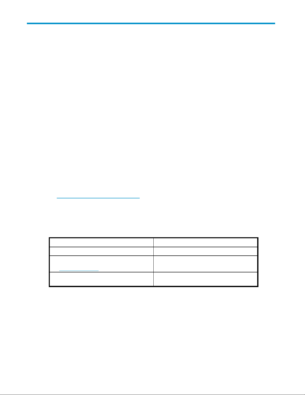
• To unify copy operations between different storage systems.
• To unify connections from a host to different storage systems.
The following subsections explain how the copy operations and the host connection will change after
Universal Volume Manager is installed.
Unifying Copy Operations between Different Storage Systems
When you copy data between different storage systems, the copy operations are usually different
depending
on the storage system which you use.
If you inst
you copy data between volumes in the storage system.
• To copy databetween avolumeinthe storagesystemandavolumeinanexternalstorage system.
• To copy dat
all External Storage, you can perform the following copy operations in the same way as when
a between a volume in an external storage system and a volume in another external
storage system.
XP24000 External Storage Software User’s Guide
13
Page 14

Figure 1 Unifying Copy Operations between Different Storage Systems
Unifying Connections from a Host to Different Storage Systems
When a system has multiple storage systems, a host usually needs to connect all storage systems. When
a system administrator configures the connections from a host to volumes, they need to follow the different
instructions depending on the storage systems.
If you install External Storage, a system administrator only needs to configure the connection from a host
to the storage system. After the configuration is completed, a host can manipulate volumes in the external
storage system in the same way as volumes in the storage system.
14
Overview of HP StorageWorks XP External Storage Software
Page 15
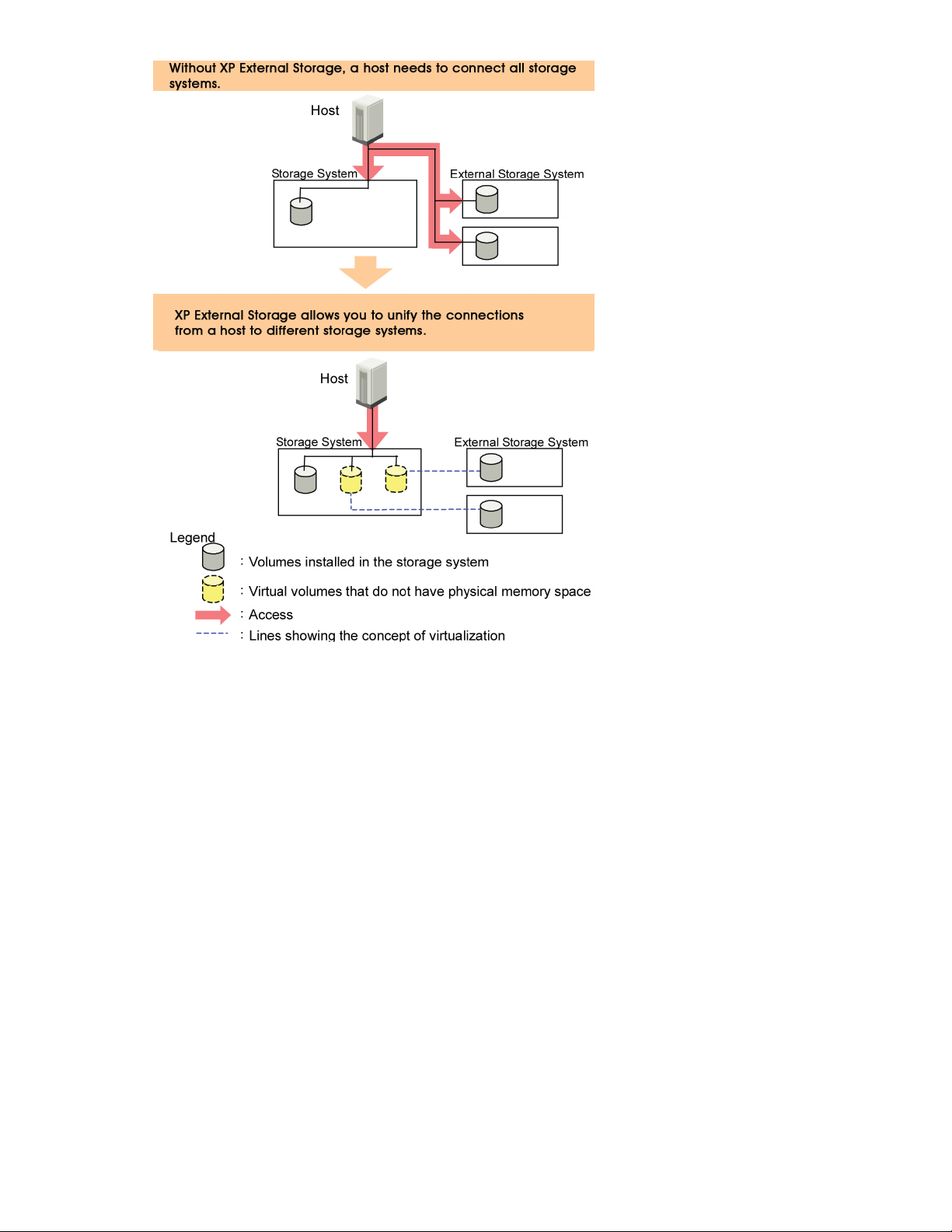
Figure 2
Unifying Connections from a Host to Different Storage Systems
XP24000 External Storage Software User’s Guide
15
Page 16

16
Overview of HP StorageWorks XP External Storage Software
Page 17

2 About External Storage Operations
This chapter explains the functions and the applications of External Storage.
This user’s guide uses the following terms:
• An original storage system is called the local storage system.
• A connected storage system is called the external storage system (other user’s guides call this
the external device).
• The volume managed in the local storage system is called the internal volume.
• The volume in the external storage system is called the external volume.
Connecting
External St
systems, and other vendors’ storage systems (such as IBM or EMC) as connectable external storage
systems. Hosts will recognize these volumes as internal volumes of the storage system.
External volume mapping is required for manipulating external volumes from storage system.
Mapping means assigning the management numbers to the external volumes. This management
numbers are required for the manipulating external volumes from storage system. By assigning the
managemen
not only i
XP Remote
sequential number (Example: E2-1, E50-3). For details on the external volume group number, see
“Registering a Volume to an External Volume Group (ExG)”onpage21.
Figure 3 on page 18 shows the idea of connection between a storage system and an external storage
system which are connected by the External Storage function. In the Figure 3 on page18, theexternal
storage system is connected to the external port of the storage system via a switch using the Fibre
Channel interface. The external port is a kind of port attribute, which is used for External Storage. In the
3 on page 18, the external volumes are mapped as storage system volumes.
Figure
Note:
Make sure that you do not access the external volume, which has been mapped as a storage
system volume, from the host that is connected to the external storage system. Also make sure that you do
not access the mapped external volume using the function (for example, copy function) of the external
storagesystem. Once youhavemappedanexternalvolumeasastoragesystem volume, you haveto
access the mapped external volume only from the storage system side.
:
From the host, you can access the external storage system volumes that have not been mapped as
Note
the storage system volumes. There is no restriction.
External Storage System
orage enables you to use HP storage systems, original equipment manufacturer (OEM) storage
t numbers to the external volumes, the system administrator will be able to manipulate
nternal volumes of storage system but also external volumes using HP StorageWorks
Web Console. The management numbers consist of external volume group number -
XP24000 External Storage Software User’s Guide
17
Page 18
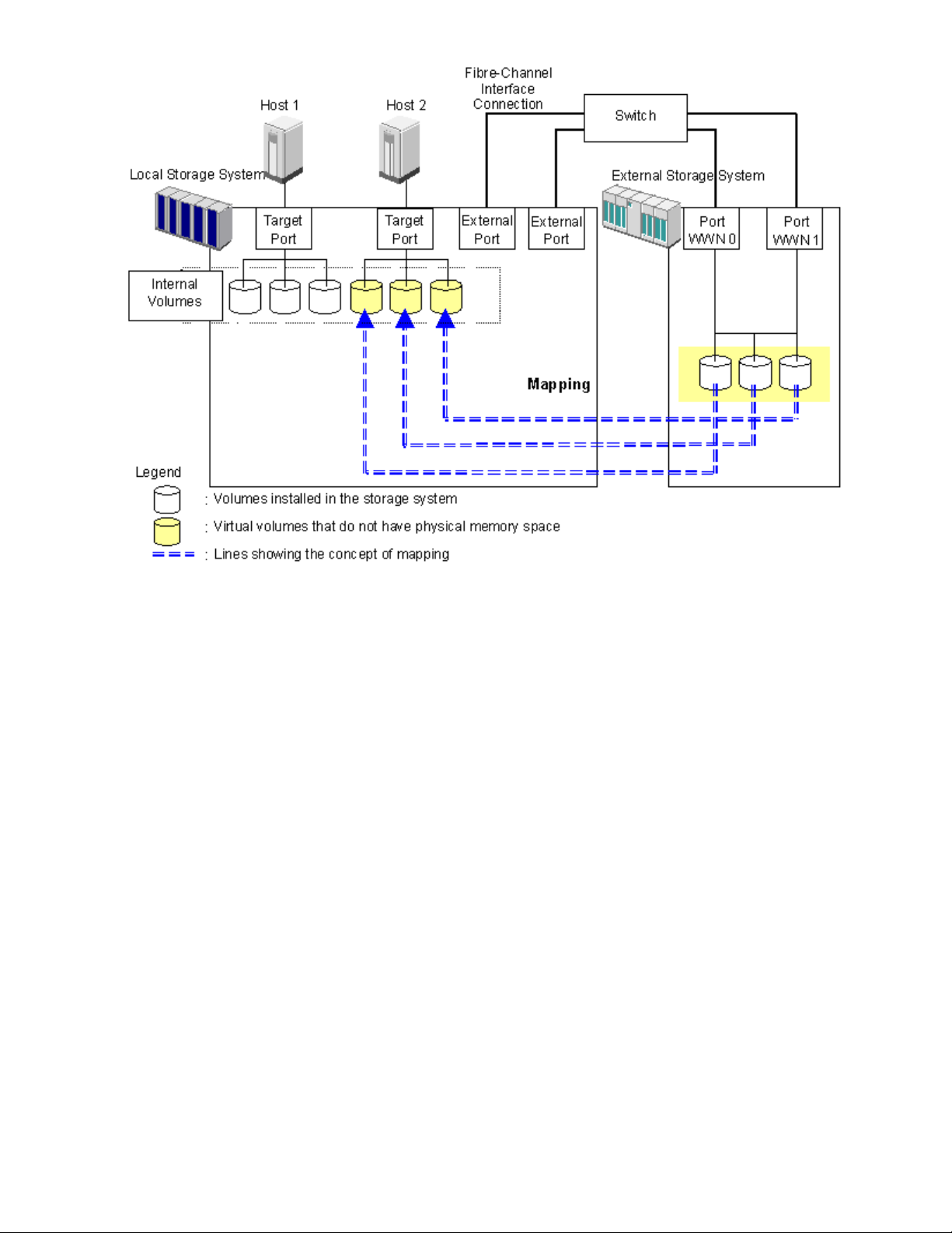
Figure 3 Concept of External Storage
By mapping an external volume as an internal volume using External Storage as shown in
Figure 3
if it is a
on page 18, it becomes possible to operate the external volume using Remote Web Console as
volume in the storage system.
External Storage Components
Systems using External Storage usually contain the following components:
• Local storage system (storage system)
• External storage system
• Remote Web Console computer
• External Storage
• External volume
• Internal volume, which is a virtual representation of an external volume
• LDEVs(LogicalDevices)inanexternalvolume
• Cross-subsystem path
• Mapping path
The following figure illustrates the relations of the External Storage components.
18
About External Storage Operations
Page 19
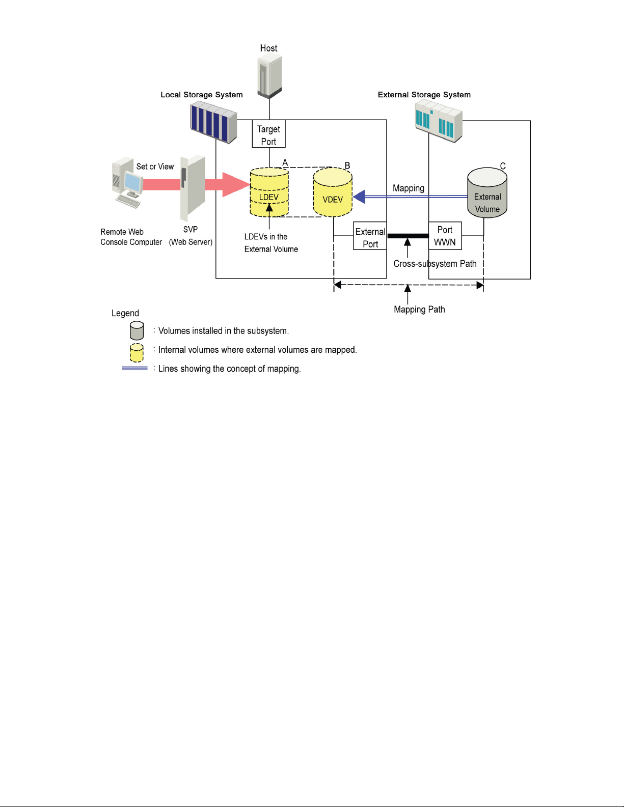
Figure 4
is section describes the details on the storage systems, cross-subsystem paths, volumes and mapping
Th
aths as shown in the above figure.
p
External Storage Components
Storage Systems and Cross-subsystem Paths
Before using External Storage, connect the Fibre Channel port of the local storage system to the external
storage system port with the fibre cable. The route between ports, which is connected with the cable, is
called the cross-subsystem path.
The Fibre Channel port of the local storage system is set to connect to the host by default. The Fibre
Channel port can be connected to an external storage system if you change the attribute of the Fibre
Channel port so that it is an external port, which can be connected to an external storage system. The
external storage system port can be a target port, which can be connected to a host.
To manipulate External Storage, you need to install External Storage by using the license key. Use your
Remote Web Console computer to access the local storage system via SVP (web server) and perform the
External Storage operations.
Volumes and Mapping Paths
Volumes in the external storage system (see C in Figure 4 on page 19) are called external volumes.
Mapping is necessary to manipulate an external volume from the local storage system. The system
administrator maps an external volume as an internal volume (see B in Figure 4 on page 19) in the local
storage system. After the mapping, you can manipulate the external volume from the local storage system
in the same way as manipulating an internal volume.
Note:
When external volumes in external storage systems are mapped as internal volumes in your
storage systems, the external volumes can be accessed and copied by hosts connecting to your storage
systems, but not by hosts connecting to the external storage systems.
XP24000 External Storage Software User’s Guide
19
Page 20

This document sometimes uses the term external volume or mapped external volume to mention an
internal volume where an external volume is mapped (see B in Figure 4 on page 19), because this
internal volume is a virtual representation of an external volume.
When you perform mapping, a path is automatically created between an internal volume and an
external volume. This path is called a mapping path, which connects one volume with another volume. A
cross-subsystem path is a part of a mapping path.
To use the external volumes, which you mapped as an internal volume (see B in Figure 4 on page 19),
from the host or other program products, the system administrator needs to create LDEVs in the external
volume (see A in Figure 4 on page 19). To create LDEVs, use External Storage at the time of mapping, or
use VLL function to an internal volume where an external volume is mapped after mapping. The LDEVs
created by these methods are called LDEVs in the external volume in this document. These LDEVs are
usually called external volumes in other documents.
An external volume corresponds to a VLL VDEV (Virtual Device). An LDEV in the external volume
corresponds to a VLL LDEV. Therefore, you can use VLL function to create custom-sized volumes in an
external volume after mapping, in the same way as creating custom-sized volumes in the normal internal
volumes. For details on VDEVs and LDEVs, see the HP StorageWorks XP24000 Virtual LVI/LUN (VLL)
and Volume Shredder User’s Guide.
External Storage Operations
External Storage enables you to execute the following operations.
• Preparing to use external volumes
You can map
paths. For details, see “Configuring External Storage” on page 20, and section
“Overview of Setting Operations”onpage67.
• Preparing to manipulate the power supply of the storage systems
You must follow specific procedures if you want to manipulate the power supply of the storage
systems when external volumes are used. To turn on or off the power supply of the external
storage
Externa
• Setting up and removing the cross-subsystem paths
When you set up or remove the path (cable) connecting the storage systems, you need
to use Ex
“Disconnecting External Storage System or Disconnecting External Volume” on page 89 and
section “Checking Connection Status and Resuming External Volume Operation” on page 91. For
details on setup, see “Configuring Cross-subsystem Path” on page 81.
• Refer
You ca
“ Checking the External Volume Details” on page 83.
• Stopping the use of external volumes
You can cancel mapping of external volumes. For details, see
“Dele
• Setting the remote command device
By using the remote command device, you can manipulate volumes in the external storage
system from the HP StorageWorks XP RAID Manager on host computers. For details, see
“Rem
l Storage. For details, see “Turning On or Off the Storage System” on page 87.
ring to the status of external volumes
n see the status and the configuration of external volumes. For details, see
ting the External Volume Mapping” on page 96.
ote Command Devices”onpage99.
external volumes, set port attributes, and set cross-subsystem
system after starting to use the external volumes, you need to execute the commands of
ternal Storage to make settings on the path. For details on removal, see
Configuring External Storage
Before configuring the External Storage settings, you need to answer the following:
• Which ports can be connected to external storage systems (see
“Choosing the External Port”on page21).
• Which external storage system and volumes should be mapped as the internal volumes (see
“Choosing and Mapping External Volumes” on page 21).
20
About External Storage Operations
Page 21

• How to configure external volume groups (see
“Registering a Volume to an External Volume Group (ExG)”onpage21).
• What external volume attributes to be configured (see
“Configuring External Volume Attributes”onpage22).
•
How to configure cross-subsystem paths (see “Cross-subsystem Paths”onpage23).
• How tomakevolumeusablefromthe localstorage system (see
“Connecting Mainframe Volumes” on page 29 and section
“Connecting Open Systems Volumes”onpage30).
Each item above is explained in the following sections.
Choosing the External Port
The port used for External Storage must be set as the external port. When the external storage system
is connected to the external port of the local storage system, you can view the information on the
external storage system from the Remote Web Console computer. The external storage system cannot be
connected
In order to set the port attribute to external, the LU paths set to the port must be released. The attribute of
theport where theLUpaths arealready set cannotbechanged to external. Therefore,you must identify
ports whose attributes can be changed to external before starting the External Storage operations.
Note:
or other features cannot be used as external ports for External Storage. In addition, change the port
attribute to external if the port attribute is set to other than external.
For instr
“Settin
to the ports other than the external port.
The ports whose attributes are set for remote copy software (for example, RCU target, initiator)
uctions on configuring port attributes, see
g Port Attribute for Local Storage System”onpage68.
Choosing and Mapping External Volumes
When you connect an external storage system to an external port, volumes in the external storage
system (external volumes) become available for mapping as volumes in the local storage system (internal
volumes). Identify the volumes in each external storage system that should be mapped as internal volumes.
• You cannot access the data that is stored in an external volume beyond the maximum available
capacity.
For example, if an external volume of 100 GB was mapped as an internal volume of 70 GB, then
30 GB of theexternalvolume would notbeaccessiblefrom the localstorage system side.
• You cannot map an external volume whose capacity is smaller than the minimum available
capacity.
For example, you cannot map an external volume of 10 GB as an internal volume which requires
at least 30 GB.
The maximum or minimum available capacity of an external volume depends on the emulation type that is
set when the volume is mapped. See “Required Volume Capacity for Each Emulation Type” on page 127
for the capacity of the external volume for each emulation type. For the maximum number of external
volumeswhich canbemapped, see“External Storage Requirements”onpage43.
stering a Volume to an External Volume Group (ExG)
Regi
When you map an external volume as an internal volume, you need to register the external volume
to an external volume group.
External volumes, which are set by External Storage, can be classified into groups by usage. Any group
of this type is called an external volume group (ExG). For instance, you can register multiple volumes
ne external storage system to one external volume group. Or you can register the volumes in one
in o
external volume group and manage them in block, even though the data you want to manage in a lump
is stored in volumes in the different external storage systems.
XP24000 External Storage Software User’s Guide
21
Page 22

You need to assign numbers to external volume groups. See “External Storage Requirements” on page 43
for details on a maximum number of external volume groups, or a maximum number of volumes to be
registered in one external volume group.
Configuring Ex
When you map an
volume. External volume attributes can be set using the mapping policy or the Set External
Volume Parameter dialog box of the External Storage. For details on the mapping policy, see
“Choosing Mapping Policy” on page 30. For details on the Set External Volume Parameter dialog box,
see “Set Exte
The attribut
• Emulation type
Select an emulation type for the mapped external volume from the drop-down list.
The emulatio
existing dat
migrate the existing data in the external volume to the local storage system volume, you have to
set the OPEN-V emulation type when the external volume is mapped.
If you selec
for management data. Once this area is provided, volume capacity after the mapping becomes
less than the actual external volume capacity for the area (volume). For details on volume
capacity, see “Capacity Guidelines”onpage45.
• Cache Mode
Cache mode specifies whether the write data from the host to the external storage system is
propagated synchronously or asynchronously. All I/O to and from the local storage system (either
Enable or Disable) always uses cache. Write operations are always backed up in duplex cache.
•If you sel
the local
asynchronously destages the data to the external storage system cache where it is then
asynchronously destaged to disk.
•If you se
complet
external storage system cache. The external storage system cache then asynchronously
destages this data to disk.
If you perform the HP StorageWorks XP Cache Residency Manager operation on the external
volume, which the Cache Mode is set to Disable, the bind mode of Cache Residency Manager
cannot be specified. For the Cache Residency Manager operation, see the HP StorageWorks
XP240
• Inflow Control (Enable or Disable)
Inflow control specifies whether the writing operation to the cache memory is stopped (Enable)or
continued (Disable) when the writing operation to the external volume is impossible. By default,
inflow control is set to Disable
•If yo
accepted when the writing operation to the external volume is impossible.
•If you select Disable, the I/O from the host during the retry operation is written to the cache
memory even after the writing operation to the external volume is impossible. Once the
wri
is written to the external volume (all the data is destaged).
• CLPR
n the cache memory is partitioned using HP StorageWorks XP Disk/Cache Partition,
Whe
figure a cache logical partition (CLPR) to access the mapped volume. Please see the HP
con
orageWorks XP24000 Disk/Cache Partition User’s Guide for the detailed information on CLPR.
St
ternal Volume Attributes
external volume as an internal volume, you set the attributes of the external
rnal Volume Parameter Dialog Box” on page 72.
es of the external volume are as follows:
ntype OPEN-V must be selected if, after the mapping, you are planning to use the
a in the external volume from the local storage system. For example, if you want to
t the emulation type other than OPEN-V,the volume requires aspecificareaprovided
(Enable or Disable)
ect Enable, after receiving the data into the local storage system cache memory,
storage system signals the host that an I/O operation has completed and then
lect Disable, the local storage system signals the host that an I/O operation has
ed only after the local storage system has synchronously written the data to the
00 Cache Residency Manager User’s Guide.
.
uselect Enable,the writingoperation to cacheisstoppedand theI/O from thehostisnot
ting operation to the external volume becomes normal, all the data in the cache memory
22
About External Storage Operations
Page 23

Cross-subsyste
A cross-subsystem path is a route from a local storage system port to an external storage system port. To
prepare for possible failures of the cable, the switch, or the channel processor, it is recommended that
you create redu
operations to the external volumes when you maintain the cable. You can set up to eight paths.
A group of redundant cross-subsystem paths is called a path group. In a path group, the cross-subsystem
path that has the highest priority is called the primary path. The cross-subsystem paths other than priority
path are calle
• Setting of the path groups
A path group is automatically set when you map the external volume. You cannot set a new
path group by itself.
• Setting of cr
Use fibre cabl
storage syst
of the local
If multiple
(that is, e
show the po
an external volume. In this dialog box, you can set cross-subsystem paths by selecting the starting
points and the ending points of the paths according to the actual cable connections. For details on
how to set cross-subsystem paths, see “Configure Cross-subsystem Paths Dialog Box”onpage78.
• Setting of redundant cross-subsystem paths
You can se
cross-subsystem paths. You can also add an alternate path or change the priority after completing
the mapping of the external volume (see “Setting the Cross-subsystem Paths” on page 78).
mPaths
ndant cross-subsystem paths. This redundancy allows you to continue performing the I/O
d alternate paths.
oss-subsystem paths
es to establish multiple paths between the external storage system and the local
em. At this time, connect to the external storage system from the different cluster port
storage system.
paths are established between the two storage systems, the starting points of the paths
xternal ports of the local storage system) and the ending points (that is, WWNs which
rts of the external storage system) will be displayed in a dialog box when you map
t redundant cross-subsystem paths (add alternate paths) when you set the
Path Mode
Path mode is either Single mode or Multi mode, depending on the connected external storage system.
• In the Single mode, only the path with the highest priority (primary path) is used to execute the
I/O to the external volume. When an error occurs in the primary path, the path with the second
highest priority is used.
• In the Multi mode, all of the set paths are used at the same time. The multiple paths are used to
executethe I/Os to theexternalvolumethusdistributing the work load (round-robin processing).
For example, when a volume in the external storage system with the path mode of the Single mode is
mapped as an internal volume using External Storage, the host I/O operations to the external volume are
enabled using the primary path set in the mapping operation. The path is automatically switched to the
alternate path when the primary path set in mapping operation cannot be used due to, for instance,
maintenance operation in the storage system, or a failure in the channel processor. Because the path is
switched to the alternate path, the I/O operation to the external volume continues even though an error
occurred in the original path.
Note:
When the primary path cannot be used for three minutes continuously, the path is switched
to the alternate path.
Examples of Alternate Paths
Figure 5 on page 24 illustrates an example of setting an alternate path. In Figure 5 on page 24, external
rage system ports, WWN A and WWN B, are connected to CL1-A and CL2-A respectively, which are
sto
t to the external ports in the local storage system. You need to specify the port of a different cluster
se
the local storage system for the alternate path. Therefore, CL1 port and CL2 port are specified as
in
shown in Figure 5 on page 24.
XP24000 External Storage Software User’s Guide
23
Page 24
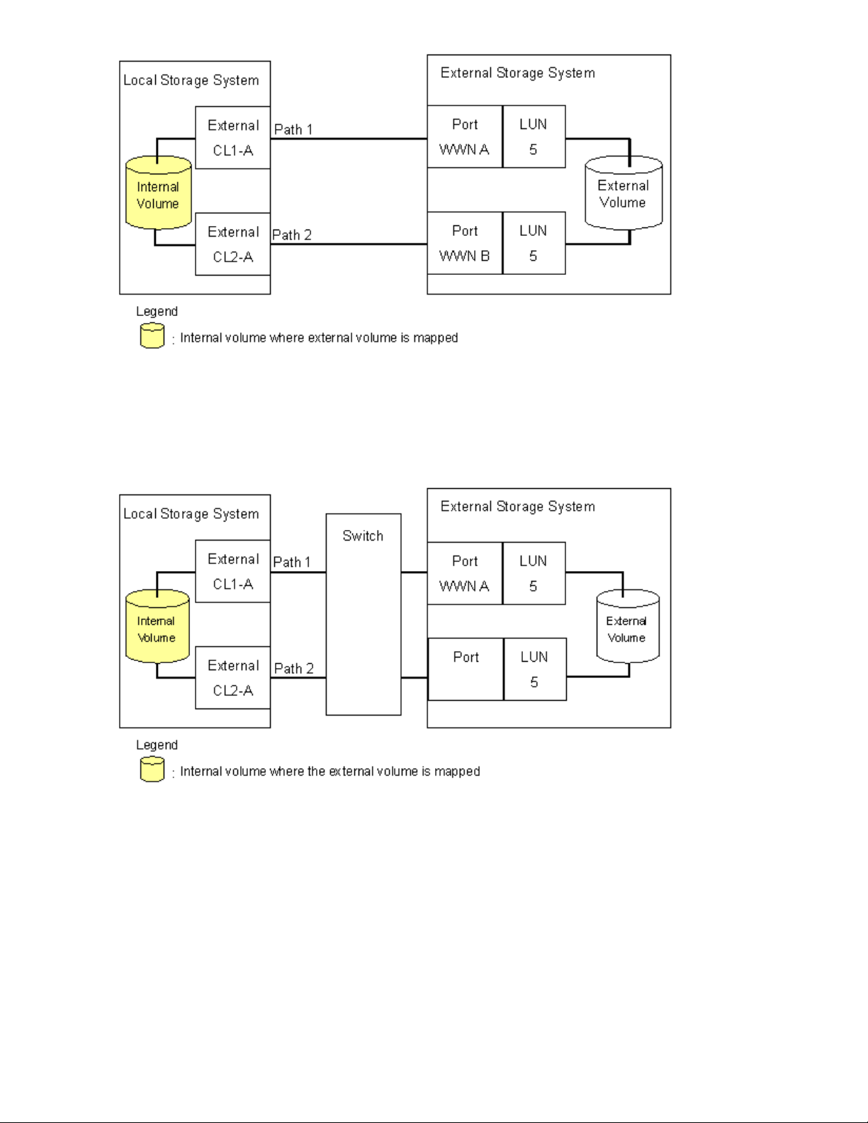
Figure 5 Example of Alternate Path Setting
Figure 6 on page 24 illustrates an example of setting an alternate path when a switch is used. In
Figure 6 on page 24, two ports are specified in the local storage system, and connected to the ports in
the external storage system through the switch. In this case, two ports of different clusters are specified in
the local storage system. Therefore, the setting of the alternate path is enabled.
Figure 6 Example of Available Alternate Path Setting
In Figure 7 on page 25, two paths are also set between the internal volume and the external volume.
However, one port is specified in the local storage system, and two ports are specified in the external
storage systems over the switch. This configuration is not recommended because two ports of different
clusters need to be set in the local storage system for alternate path settings in External Storage.
24
About External Storage Operations
Page 25

Figure 7 Example of Unavailable Alternate Path Setting
Examples of Switching I/O Execution Paths to Alternate Paths
This section describes the case examples of the performance when the I/O execution path is switched to
the alternate path for each path mode as follows:
• When the path mode is Multi mode.
• When thepathmodeis Singlemode.
• When the path mode is Single mode and there is at least one alternate path in the Standby status.
For the description about the path status, see “Mapping Path Information Dialog Box” on page 84.
• When the path mode is Multi mode
Figure 8 on page 26 shows an example of the case when the path mode is Multi mode. When
an error occurs in one path, I/Os are executed using the paths other than the error path.
Note:
As you restore the error path, the use of the restored path is automatically resumed.
XP24000 External Storage Software User’s Guide
25
Page 26

Figure 8 When the Path Mode is Multi Mode
• When t
Figur
an err
he path mode is Single mode
e 9 on page 27 shows an example of the case when the path mode is Single mode. When
or occurs in the path that is being used for I/Os, the I/O execution path is switched to the
path with the second highest priority.
Note:
As you restore the path with the priority higher than the currently used path, the I/O
execution path is automatically switched to the restored path that has the highest priority.
26
About External Storage Operations
Page 27
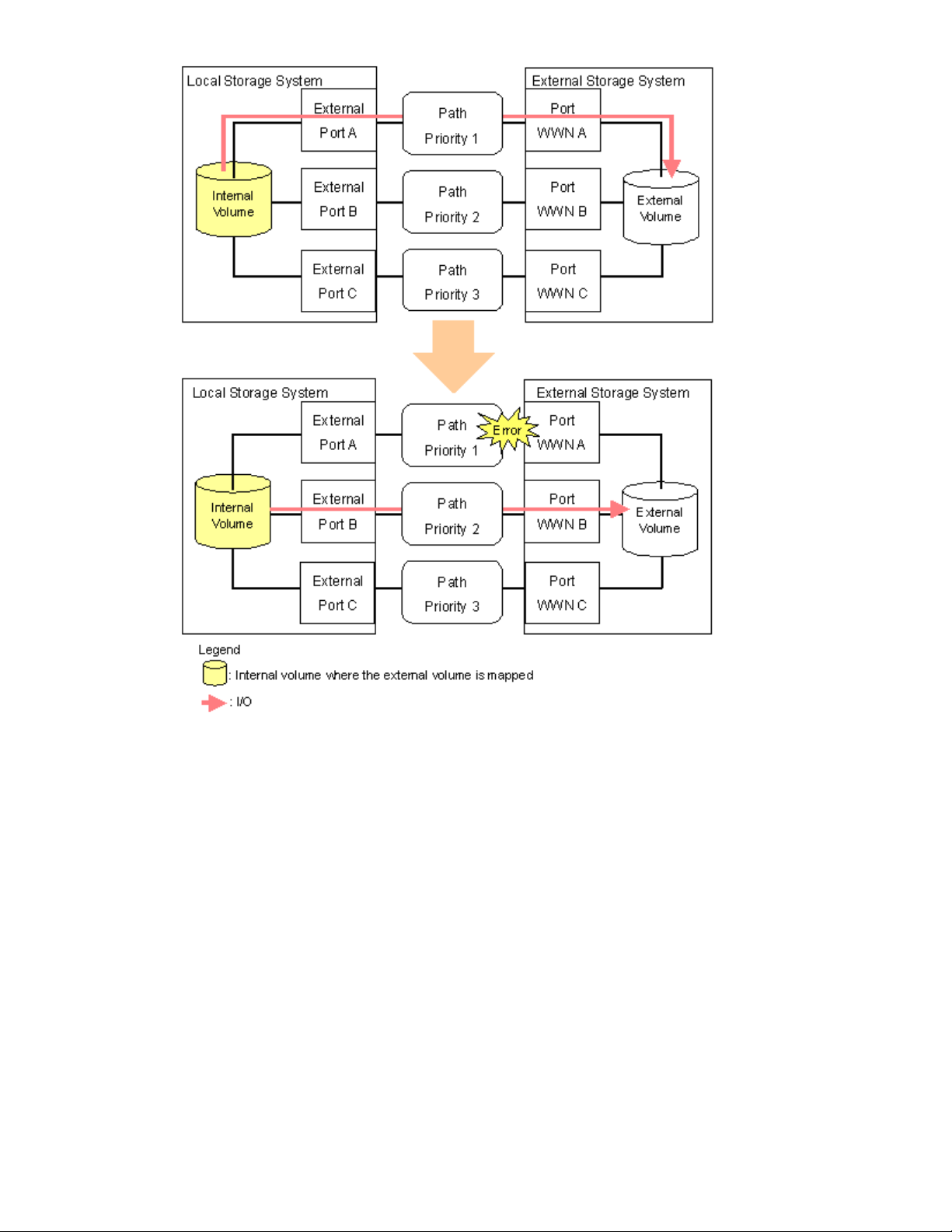
Figure 9 When the Path Mode is Single Mode
• When t
Figur
he path mode is Single mode and there is at least one alternate path in the Standby status
e10 on page 28 shows an example of the case when the path mode is Single mode, and
there are the alternate paths in the Normal status and the Standby status. Figure 11 on page 29
shows another example of the case when the path mode is Single mode. In the case of
Figure 11 on page 29, there are alternate paths in the Standby status only.
When an error occurs in the path that is being used for I/Os, the I/O execution path is switched
to the path with the second highest priority in the Normal status (see Figure 10 on page 28). If
there is no path in the Normal status other than the path that is being used for I/Os, the status of
the path in the Standby status is automatically changed to Normal, and the I/O execution path is
tched to that path (see Figure 11 on page 29).
swi
Note:
Only when the external storage system is EVA storage system, as you restore the path with
the highest priority, the I/O execution path is switched back to the restored highest priority path.
In this case, the status of the path for which the status has been changed to Normal when the
error has occurred is changed back to Standby.
XP24000 External Storage Software User’s Guide
27
Page 28
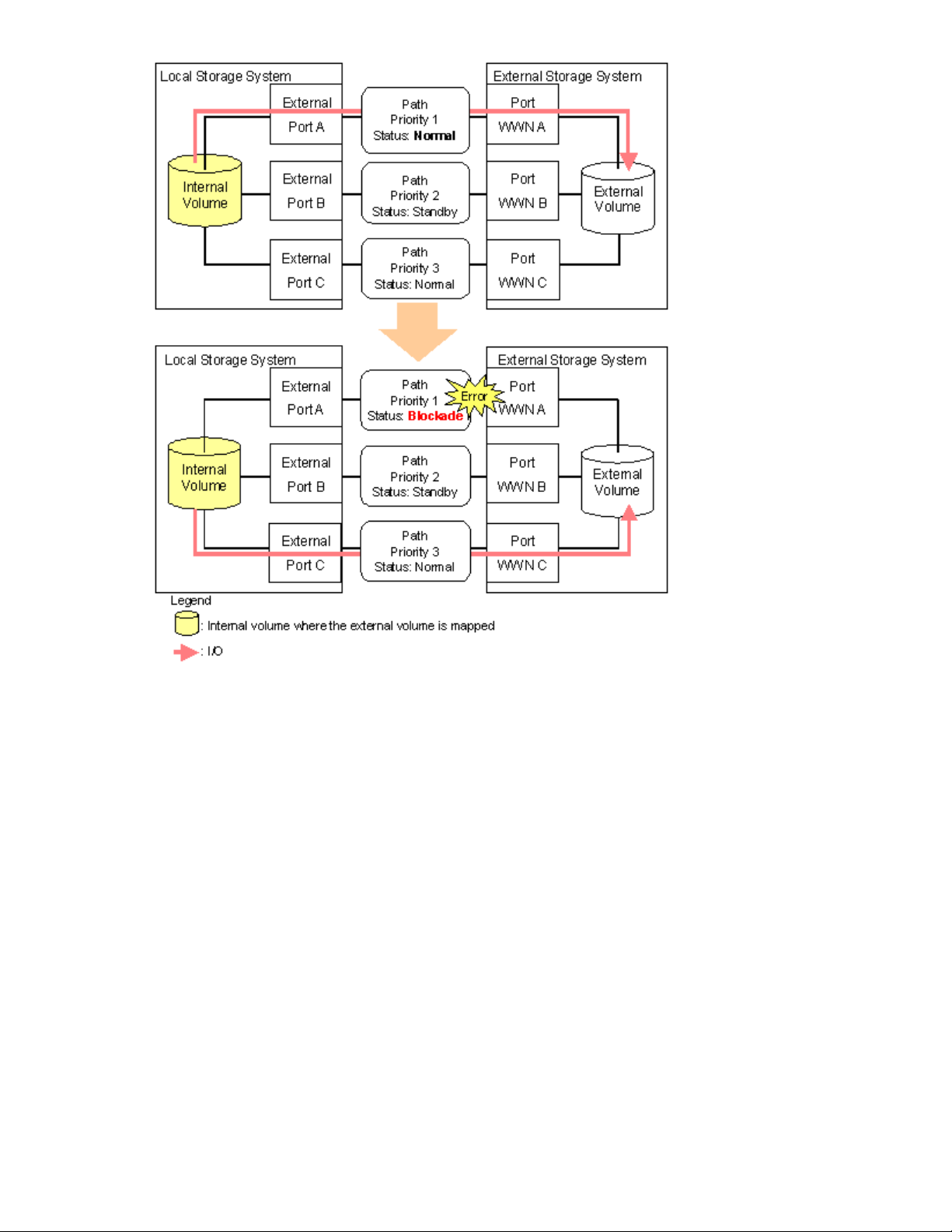
Figure 10 Single Mode with Alternate Paths in Normal and Standby
28
About External Storage Operations
Page 29
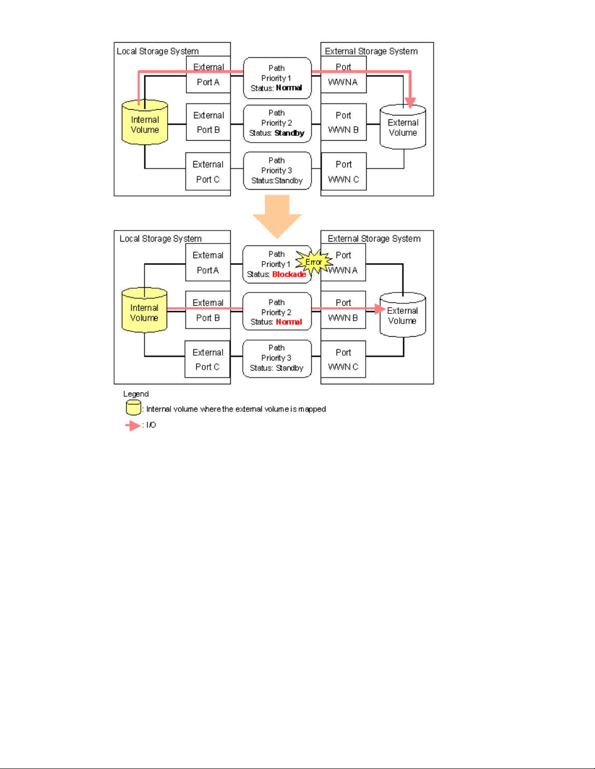
Figure 11 Single Mode with Alternate Paths in Standby only
Connecting Mainframe Volumes
Mainframe volumes, that pre-exist on an external storage system and are accessed by ESCON or FICON
channels, cannot connect directly to the storage system as an external volume. The storage system does
not recognize these volumes because of the Fibre Channel.
To use external volumes as mainframe volumes, there are two ways:
• Zero-format external volumes on the external storage system side, map the external volumes to the
internal volumes using External Storage on the local storage system side, and then perform the
Write to Control Blocks operation using the VLL function on the local storage system side.
• Map the external volumes to the internal volumes using External Storage on the local storage
system side, and then format the mapped external volumes using the VLL function on the local
storage system side.
If you set the emulation type for the mainframe system (such as 3380 or 3390, shown in
“Required Volume Capacity for Each Emulation Type” on page 127) as you map the external volume,
the status of the mapped volume becomes Blockade after the mapping operation. After the system
administrator performs the Write to Control Blocks operation or formats the mapped external volumes
using VLL function on the local storage system side, the mainframe host can then access the new
mainframe volume through the local storage system’s ESCON or FICON channels.
XP24000 External Storage Software User’s Guide
29
Page 30

Note:
If you format the mapped volume of the external storage system from the external storage system
side, the existing data before formatting cannot be assured. When you use the mapped external volume
from the mainframe OS, format the mapped volume from the local storage system side.
For the procedure of the volume formatting operation and the Write to Control Blocks operation, see the
HP StorageWorks XP24000 Virtual LVI/LUN (VLL) and Volume Shredder User’s Guide.
Connecting Open Systems Volumes
Open systems
as open syst
connection
to initiali
of the volu
Volume Shredder User’s Guide.
OPEN-V emulation is recommended because, in most cases, OPEN-V emulation provides the most
efficient u
retain ex
volumes in external storage system connect to and are recognized by the storage system
ems volumes, without requiring reformatting. Reformatting is not required because the
between the storage system and the external storage system is Fibre Channel. If you need
ze the data area for the volume, format the volume using the VLL function. For the procedure
me formatting operation, see the HP StorageWorks XP24000 Virtual LVI/LUN (VLL) and
se of storage and the best performance. Also, emulation types other than OPEN-V may not
isting data after being mapped.
Choosing Mapping Policy
Policy is a list of settings of the necessary information for mapping the external volume. By setting the
mapping policy in advance, the setting at the time of mapping will be easier.
Two policies are prepared in advance. The user can change the default value of the policy. For details on
the default value, see “Edit Policy Dialog Box” on page 95.
Difference between Automatic Mapping and Manual Mapping
When you map the external volume, you need to configure:
• cross-subsystem paths
• extern
• LDEV number to LDEVs in the external volume
• SSID
When yo
settings above are automatically made by External Storage according to the mapping policy. When you
perform manual mapping, users configure all the settings.
al volume parameters
u perform automatic mapping, users configure only cross-subsystem paths and all the other
Automatic mapping maps all the external volume found by the Volume Discovery to the internal volumes.
Automatic mapping requires less settings but you are not allowed to set different parameters to each
external volumes or to specify LDEV number to each LDEVs. You can set the parameters such as emulation
type to mapping policy in advance.
For the procedure of automatic mapping, see “Mapping an External Volume Automatically” on page 69.
For the procedure of manual mapping, see “Mapping an External Volume Manually” on page 69.
Port Discovery and Volume Discovery
Port Discovery and Volume Discovery are the methods used to find external volumes, and will be executed
when you map external volumes or when you add cross-subsystem paths.
Port Discovery is a process to search for and get information about target ports of the connected external
storage system from an external port of the local storage system. The latest information about the external
storage system can be displayed in a dialog box of External Storage when you execute Port Discovery.
You can set in advance the mapping policy on whether to execute the Port Discovery automatically or
manually. If Port Discovery is executed automatically, WWNs connected to all the external ports of the
local storage system will be searched for. If Port Discovery is executed manually, you can select a specific
30
About External Storage Operations
Page 31

external port and limit the scope to search WWNs. If you can specify which external port to search for,
you can reduce the operation time by executing the Port Discovery manually.
Volume Discovery is a process to search for and get information about external volumes from the
target ports of the external storage system. Volume Discovery is automatically executed after the Port
Discovery process.
Using a Mapped External Volume from a Connected Host
There are two ways of using the mapped external volume from a host that is connected the local
storage syste
• Storing the new data in the mapped external volume (see
“Storing New Data in the Mapped External Volume” on page 31)
• Using the exi
“Using Existing Data in the Mapped External Volume” on page 32)
Storing New Data in the Mapped External Volume
To store new data in a mapped external volume from a host that is connected to the local storage system:
1. Map the volume in the external storage system as an internal volume of the local storage system
using External Storage.
Select the emulation type of the mapped volume as you required. If you select the emulation
type for the open system (such as OPEN-V), go to step 2. If you select the emulation type for the
mainframe system (such as 3390-3), go to step 3.
For information on mapping operations, see
“Mapping an External Volume Automatically”onpage69.
2. If you set the emulation type for the open system when you map the volume, the status of the
mapped volume automatically becomes Normal. If you need to initialize the data area of the
mapped volume, format the volume using the VLL function. For the volume formatting procedure,
see the HP StorageWorks XP24000 Virtual LVI/LUN (VLL) and Volume Shredder User’s Guide.
Go to step 4.
3. If you set the emulation type for the mainframe system when you map the volume, the status of
the mapped volume becomes Blockade. Format the volume using the VLL function.
Note: For zero-formatted external volumes, when you select that volume to map, you can use
the VLL function to perform the Write to Control Blocks operation to restore the volume. For
instructions on how to format volumes and the Write to Control Blocks operation, see the HP
StorageWorks XP24000 Virtual LVI/LUN (VLL) and Volume Shredder User’s Guide.
Go to step 4.
4. To perform the host I/O operations, set the LU path from the Target port to the mapped volume.
After the LU path is set, the host I/O operation to the mapped volume becomes available.
m.
sting data in the mapped external volume (see
XP24000 External Storage Software User’s Guide
31
Page 32

Figure 12 Storing the New Data in the Mapped External Volume
Using Existing Data in the Mapped External Volume
To use the existing data in the mapped external volume from the host that is connected to the local
storage system:
1. Store the data from the host that is connected to the external storage system to the volume in
the external storage system.
2. Map the volume containing data in the external storage system as an internal volume of the
local storage system using External Storage.
When you map the external volume, set the attributes of the mapped volume as follows:
•Emulation type: OPEN-V
For information on mapping operations, see
“Mapping an External Volume Automatically”onpage69.
Note:
You have to set the emulation type to OPEN-V to read the existing data in the mapped
external volume from the local storage system side.
3. Set the LU path from the Target port to the mapped volume to perform the host I/O operation.
After the LU path is set, the host I/O operation to the mapped volume can be initiated.
Note:
Make sure that you do not access the external volume, which has been mapped as a internal
volume, from the host that is connected to the external storage system. Also make sure that you do not
access the mapped external volume using the function (for example, copy function) of the external storage
system. Once you have mapped an external volume as an internal volume, you can access the mapped
external volume only from the local storage system side.
Note:
From the host, you can access the external storage system volumes that have not been mapped
as the internal volumes. There is no restriction.
32
About External Storage Operations
Page 33

Figure 13 Using the Existing Data in the Mapped External Volume
Interope
rability with other Products and Functions
Youcan usethe storagesystemprogram products to utilizeand to manage theexternalvolumes you
have set using External Storage.
The storage system program products that support the use of mapped external volume are explained in
the following subsections. For the operations and notes on each program product, see the respective
user’s g
uides.
HP StorageWorks XP LUN Manager
If you set the emulation type for the open system as you map the external volume, you need to set the LU
path for the mapped volume using LUN Manager.
Consider the following for the Configuration File Loader function:
• You can to set the LU path definition for the external volume (add, delete, or change LU paths).
• You can to set the command device for the external volume (add or delete the setting).
• The setting of the channel adapter (CHA) mode, host group, and WWN for the external port
is not supported. When an external volume is mapped through that external port, the setting
operation of the topology is not available, either.
HP StorageWorks XP LUN Expansion (LUSE)
Consider the following for LUN Expansion (LUSE):
• The s
torage system internal volume and the external volume cannot be combined to form a
LUSE volume.
XP24000 External Storage Software User’s Guide
33
Page 34

• Do not combine LDEVs of multiple external volumes to create a LUSE volume. Only the LDEVs in
the same external volume can be used to configure the LUSE volumes.
• The external volumes, for which the different Cache Mode is set, cannot be combined to form
aLUSE volume.
HP StorageWorks XP Virtual LVI/LUN (VLL)
Consider the following for Virtual LVI/LUN (VLL):
• If you set the e
to format the mapped volume or perform the Write to Control Blocks operation using the VLL
function before you use the external volume.
For the formatting operation procedure and the Write to Control Blocks operation procedure, see
the HP StorageWorks XP24000 Virtual LVI/LUN (VLL) and Volume Shredder User’s Guide.
• If you create
LDEVs becom
mulation type for the mainframe system as you map the external volume, you need
LDEVs in an external volume using the VLL function, the cache mode of the created
e the same as those of the source external volume.
Cache Residency Manager
Consider the following for Cache Residency Manager:
• Thebindmodeofthe CacheResidency Manageroperation cannot be specified for the external
volume if the Cache Mode is set to Disable.
• If you use the mapped external volume for the Cache Residency Manager operation and set
the bind mode, a cache of twice as much capacity as the user data is required for the Cache
Residency Manager operation.
HP Stora
LUN Soft
geWorks XP Performance Monitor and HP StorageWorks XP Auto
ware
Consider the following for Performance Monitor and Auto LUN:
• Performance Monitor can be used to display the monitoring information about the external
volumes
• Mapped volumes can be used for Auto LUN. For adjusting volume capacity, see
“Adjusting Volume Capacities for Pairs”onpage133.
For the configuration example of Auto LUN, see “Auto LUN Operations” on page 35.
.
HP StorageWorks XP Continuous Access Software
Mapped volumes can be used for Continuous Access. For adjusting volume capacity, see
“Adjusting Volume Capacities for Pairs” on page 133.
For the configuration example of Continuous Access, see “Continuous Access Operations” on page 36.
TrueCopy for Mainframe
ed volumes can be used for TrueCopy for Mainframe. For adjusting volume capacity, see
Mapp
usting Volume Capacities for Pairs” on page 133.
“Adj
HP StorageWorks XP Continuous Access Journal Software
Mapped volumes can be used for Continuous Access Journal. For adjusting volume capacity, see
“Adjusting Volume Capacities for Pairs” on page 133.
For the configuration example of Continuous Access Journal, see
“Continuous Access Journal Operations” on page 37.
34
About External Storage Operations
Page 35

Universal Repli
Mapped volumes can be used for Universal Replicator for Mainframe. For adjusting volume capacity, see
“Adjusting Volume Capacities for Pairs”onpage133.
cator for Mainframe
HP StorageWorks XP Business Copy Software
Mapped volumes can be used for Business Copy. For adjusting volume capacity, see
“Adjusting Volume Capacities for Pairs”onpage133.
For the configuration example of Business Copy, see “Business Copy Operations” on page 39.
ShadowImage for Mainframe
Mapped volumes can be used for Business Copy for Mainframe. For adjusting volume capacity, see
“Adjusting Volume Capacities for Pairs”onpage133.
HP StorageWorks XP Snapshot
Mappedvolumes canbeusedfor XP Snapshot. For adjusting volume capacity, see
“Adjusting Volume Capacities for Pairs”onpage133.
SNMP Agent
Consider the following for SNMP Agent:
• The inform
• The information on the External port is displayed.
ation on the mapped external volume is displayed.
Examples of Using External Volumes with Other Products
For the following storage system program products, the examples of using external volumes are described
in the following subsections:
•
Auto LUN (see “Auto LUN Operations” on page 35)
•
Continuous Access (see “Continuous Access Operations” on page 36)
•
Continuous Access Journal (see “Continuous Access Journal Operations” on page 37)
•
Business Copy (see “Business Copy Operations” on page 39)
•
XP Snapshot(see“XP Snapshot Operations” on page 40)
Auto LUN Operations
Figure 14 on page 36 shows the use of an external volume for the Auto LUN operation. In
Figure 14 on page36, themappedexternalvolumeisset as thesourcevolumeand thelocal internal
e is set as the target volume. Existing data in the external volume is migrated manually to the local
volum
ge system internal volume using Auto LUN. For detailed information on the Auto LUN operation, see
stora
PStorageWorksXP24000AutoLUNSoftwareUser’sGuide.
the H
rocedure for the operation is described as follows:
The p
1. Use External Storage to map a volume in the external storage system as an internal volume
of thelocal storagesystem.
For the case such as Figure 14 on page 36, set the attributes of the mapped volume as follows:
• Emulation type: OPEN-V
details on the mapping operation, see
For
“Mapping an External Volume Automatically”onpage69.
XP24000 External Storage Software User’s Guide
35
Page 36

Note:
To migrate the existing data in the mapped external volume to the local storage system
volume using Auto LUN, set the emulation type to OPEN-V as you map the volume. The
emulationtypemustbe OPEN-V to read out the existing data in the external volume from the
local storage system side.
Caution:
products of Remote Web Console such as Continuous Access and Business Copy, the emulation
type of the mapped external volume also has to be OPEN-V.
2. Prepare the local internal volume that has the same capacity as the mapped external volume.
Adjust the capacity of the internal volume as it is required using the LUSE function and VLL
function.
For the LUSE function, see the HP StorageWorks XP24000 LUN Expansion User’s Guide.For the
VLL function, see the HP StorageWorks XP24000 Virtual LVI/LUN (VLL) and Volume Shredder
User’s Guide.
Note:
3. Set the mapped external volume as the source volume and local storage system internal volume
as the target volume.
4. Migrate the existing data in the mapped external volume to the local storage system internal
volume manually using Auto LUN.
To copy the existing data in the mapped external volume using the copy program
The emulation type of the prepared internal volume must be OPEN-V.
Figure 14 Example of the Auto LUN Operation
Continuous Access Operations
Figure 15 on page 37 shows the use of an external volume for the Continuous Access operation. In
Figure 15 on page 37, the mapped external volume is set as the S-VOL of the Continuous Access pair,
and the volume in the local storage system that is connected as the multipoint control unit (MCU) is set as
the P-VOL of the Continuous Access pair. For details on Continuous Access, see the HP StorageWorks
XP24000 Continuous Access Software User and Reference Guide.
rocedure for the operation is described as follows:
The p
1. Use External Storage to map a volume in the external storage system as an internal volume of
the local storage system, which is used as remote control unit (RCU) for the Continuous Access
operation.
an select the emulation type of the mapped volume as you required. If you select the
You c
emulation type for the open system (such as OPEN-V), go to step 2. If you select the emulation
type forthe mainframesystem(such as 3390-3), gotostep3.
36
About External Storage Operations
Page 37

For details on the mapping operation, see
“Mapping an External Volume Automatically”onpage69.
2. If you set the emulation type for the open system when you map the volume, the status of the
mapped volume automatically becomes Normal. However, the volume formatting processing
is not executed automatically. If you need to format the mapped volume, format the volume
using the VLL function.
For the volume formatting operation procedure, see the HP StorageWorks XP24000 Virtual
LVI/LUN (VLL) and Volume Shredder User’s Guide.
Go to step 4.
3. If you set the emulation type for the mainframe system when you map the volume, the status of
the mapped volume becomes Blockade. Format the volume using the VLL function. Or if you
have mapped the volume for which the data area has already been zero-formatted on the
external storage system side, perform the Write to Control Blocks operation using the VLL function
to restore the volume.
For the volume formatting operation procedure and the Write to Control Blocks operation
procedure, see the HP StorageWorks XP24000 Virtual LVI/LUN (VLL) and Volume Shredder
User’s Guide.
Go to step 4.
4.
Set the P-VOL and S-VOL of the Continuous Access pair, as shown in Figure 15 on page 37.
Figure 15 Example of the Continuous Access Operation
Continuous Access Journal Operations
Figure 16 on page 39 shows the use of an external volume for the Continuous Access Journal operation.
In Figure 16 on page 39, the mapped external volume is set as the S-VOL of the Continuous Access
Journal pair, and the volume in the local storage system that is connected as the MCU is set as the
P-VOL of the Continuous Access Journal pair. For details on Continuous Access Journal, see the HP
StorageWorks XP24000 Continuous Access Journal Software User and Reference Guide.
The procedure for the operation is described as follows:
XP24000 External Storage Software User’s Guide
37
Page 38

1. Use External Storage to map the volume in the external storage system as an internal volume of
the local storage system, which is used as RCU for the Continuous Access Journal operation.
You can select the emulation type of the mapped volume as you required. If you select the
emulation type for the open system (such as OPEN-V), go to step 2. If you select the emulation
type forthe mainframesystem(such as 3390-3), gotostep3.
For details on the mapping operation, see
“Mapping an External Volume Automatically”onpage69.
2. If you set the emulation type for the open system when you map the volume, the status of the
mapped volume automatically becomes Normal. However, the volume formatting processing
is not executed automatically. If you need to format the mapped volume, format the volume
using the VLL function.
For the volume formatting operation procedure, see the HP StorageWorks XP24000 Virtual
LVI/LUN (VLL) and Volume Shredder User’s Guide.
Go to step 4.
3. If you set the emulation type for the mainframe system when you map the volume, the status of
the mapped volume becomes Blockade. Format the volume using the VLL function. Or if you
have mapped the volume for which the data area has already been zero-formatted on the
external storage system side, perform the Write to Control Blocks operation using the VLL function
to restore the volume.
For the volume formatting operation procedure and the Write to Control Blocks operation
procedure, see the HP StorageWorks XP24000 Virtual LVI/LUN (VLL) and Volume Shredder
User’s Guide.
Go to step 4.
4. Set the P-VOL and S-VOL of the Continuous Access Journal pair, as shown in
Figure 16 on page 39.
38
About External Storage Operations
Page 39
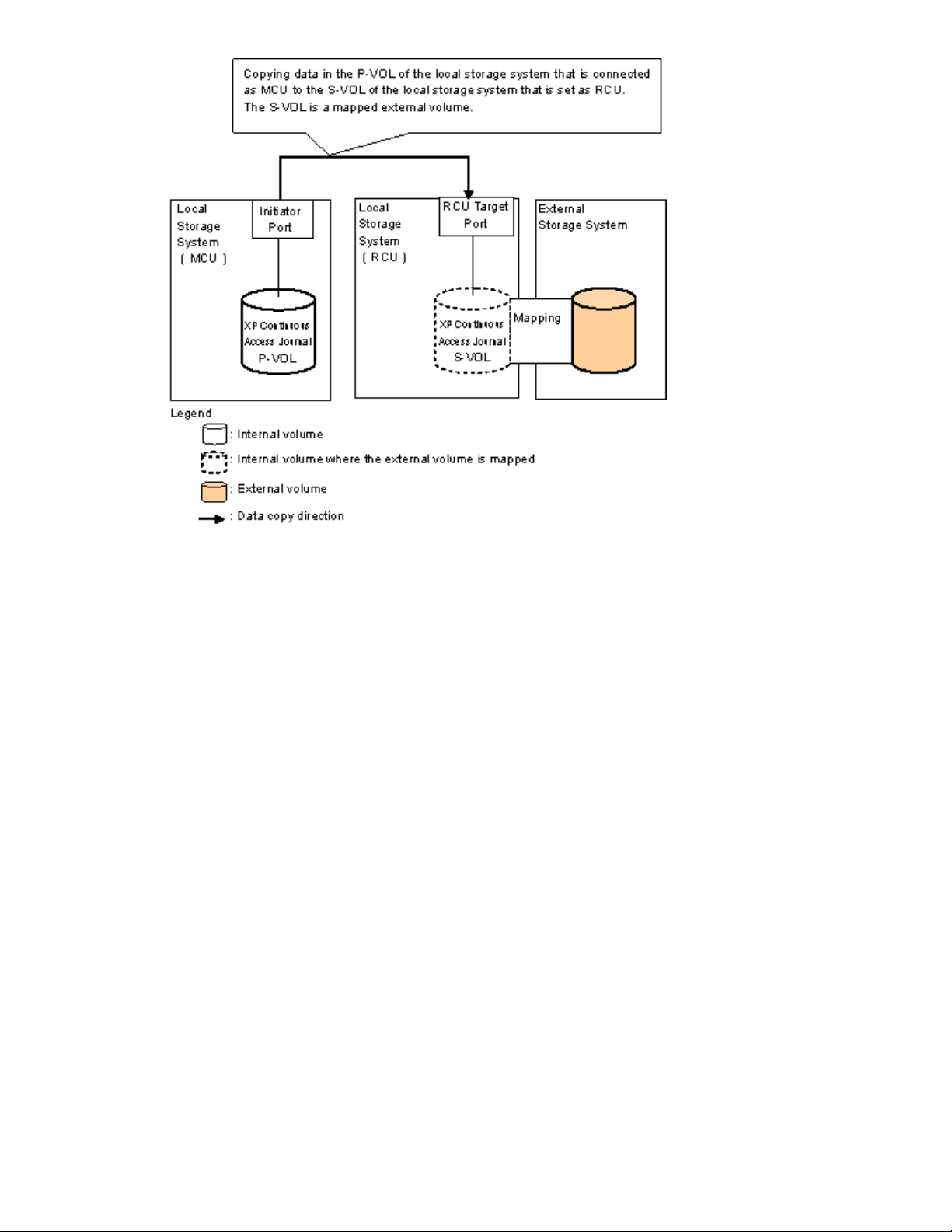
Figure 16
Example of the Continuous Access Journal Operation
Business Copy Operations
Figure 17 on page 40 shows the use of an external volume for the Business Copy operation. In
Figure 17 on page 40, the mapped external volume is set as the S-VOL of the Business Copy pair, and
the local storage system internal volume is set as the P-VOL of the Business Copy pair. For details on
Business Copy, see the HP StorageWorks XP24000 Business Copy Software User’s Guide.
The procedure for the operation is described as follows:
1. Use External Storage to map a volume in the external storage system as an internal volume
of thelocal storagesystem.
You can select the emulation type of the mapped volume as you required. If you select the
emulation type for the open system (such as OPEN-V), go to step 2. If you select the emulation
type for the mainframe system (such as 3390-3), go to step 3.
For details on the mapping operation, see
“Mapping an External Volume Automatically”onpage69.
2. If you set the emulation type for the open system when you map the volume, the status of the
mapped volume automatically becomes Normal. However, the volume formatting processing
is not executed automatically. If you need to format the mapped volume, format the volume
using the VLL function.
For the volume formatting operation procedure, see the HP StorageWorks XP24000 Virtual
LVI/LUN (VLL) and Volume Shredder User’s Guide.
Go to step 4.
3. If you set the emulation type for the mainframe system when you map the volume, the status of
the mapped volume becomes Blockade. Format the volume using the VLL function. Or if you
have mapped the volume for which the data area has already been zero-formatted on the
external storage system side, perform the Write to Control Blocks operation using the VLL function
to restore the volume.
XP24000 External Storage Software User’s Guide
39
Page 40

For the volume formatting operation procedure and the Write to Control Blocks operation
procedure, see the HP StorageWorks XP24000 Virtual LVI/LUN (VLL) and Volume Shredder
User’s Guide.
Go to step 4.
4.
Set the P-VOL and S-VOL of the Business Copy pair, as shown in Figure 17 on page 40.
Figure 17 Example of the Business Copy Operation
XP Snapsh
Figure 18 on page 41 shows the use of an external volume for the XP Snapshot operation. In
Figure 18 on page 41, the mapped external volume is set as a pool-VOL of the XP Snapshot pair. For
details
The proc
1. Use External Storage to map a volume in the external storage system as an internal volume
2. The status of the mapped volume automatically becomes Normal. However, the volume
3. Crea
4. Set the P-VOL and S-VOL of the XP Snapshot pair with specifying the pool you have created
ot Operations
on XP Snapshot, see the HP StorageWorks XP24000 Snapshot User’s Guide.
edure for the operation is described as follows:
of the local storage system.
Caution:
the volume with the OPEN-V emulation type can only be set as a pool-VOL of XP Snapshot.
For det
“Mapping an External Volume Automatically”onpage69.
formatting processing is not executed automatically. If you need to format the mapped volume,
format the volume using the VLL function. For the volume formatting operation procedure, see the
HP StorageWorks XP24000 Virtual LVI/LUN (VLL) and Volume Shredder User’s Guide.
at step 3.
Set the emulation type of the volume to OPEN-V when you map the volume, because
ails on the mapping operation, see
te a pool and add the mapped external volume to that pool as a pool-VOL.
40
About External Storage Operations
Page 41

Figure 18
Example of the XP Snapshot Operation
XP24000 External Storage Software User’s Guide
41
Page 42

42
About External Storage Operations
Page 43

3 Preparing for External Storage Operations
This chapter describes the requirements, preparations, and notes on the External Storage operations.
System Requirements
The system requirements for External Storage are:
• Storage syst
All the neces
installed a
• Storage system other than the first storage system
A second storage system must be available and operate as an external storage system. The
kinds of storage systems that can be used as an external storage system include the EVA
8000, EVA 50
informati
“Storage Systems Supported as External Storage Systems”onpage43.
• Remote Web Console computer (user-supplied computer)
Please see
on installing and using the Remote Web Console computer.
Note:
Storage operations. Users in View mode can only view External Storage information.
• License k
You need a license key to install External Storage.
em (First storage system)
sary hardware and microcode required for External Storage operations must be
nd enabled. In this user’s guide, the first storage system is called local storage system.
00, and MSA storage systems, and other similar storage systems. For detailed
on on the storage systems that can be used as the external storage system, see
the HP StorageWorks XP24000 Remote Web Console User’s Guide for instructions
You must operate the Remote Web Console computer in Modify mode to perform External
ey for External Storage program product
Storage Systems Supported as External Storage Systems
For the storage systems that are currently supported as external storage, contact HP.
External Storage Requirements
The following table describes the External Storage requirements.
XP24000 External Storage Software User’s Guide
43
Page 44

Table2ExternalStorageRequirements
Item
Maximum number of ports in the
connected external storage system
(WWN is used as
number)
Maximum number of external volumes
which can be connected
Maximum number of mapping paths
can be set for one external volume
Maximum capacity of an external
volume
Minimum capacity of an external volume
Maximum number of external volume
groups
a port identification
Requirement
1, 02 4 p e r p o r t
63,232 volumes can be connected.
4,096 volumes can be connected per port.
Note:
If you use XP Snapshot or HP StorageWorks XP Thin
Provisioning Software, the number of external volumes which
can be connected is as follows:
Number of external volumes + Number of virtual volumes ≤
63,232
8
2TBper external volume
If you specify an external volume which is more than 2 TB you
can access the data stored in the field up to 2 TB. You cannot
access the data that is stored in the field over 2 TB.
77,760 blocks (about 38 MB) per external volume.
However, when the emulation type of the volume is OPEN-V,
the minimum capacity becomes 96,000 blocks (about 47 MB)
per external volume
16 ,3 8 4
Maximum n
which can
volume g
umber of external volumes
be registered in one external
roup
4,096
Guidelines for External Storage Operations
Guidelines for the External Storage operations are as follows:
Mappin
Recommended Applications according to the HDD Type
gGuidelines
• Make sure that you do not access the external volume, which has been mapped as a storage
system volume, from the host that is connected to the external storage system. Also make sure that
you do not access the mapped external volume using the function (for example, copy function) of
ternal storage system. Once you have mapped an external volume as a storage system
the ex
e, you have to access the mapped external volume only from the storage system side.
volum
• From the host, you can access the external storage system volumes that have not been mapped as
the storage system volumes. There is no restriction.
• Do no
Table 3 on page 45 and Table 4 on page 45 show the recommended level of the application of mapped
external volume according to the HDD type of the external volume.
t map multiplatform volumes of external storage systems as internal volumes.
44
Preparing for External Storage Operations
Page 45

Table3WhentheEmulationTypeoftheExternalVolumeisforOPEN
Application
HDD Type
FC SATA
Database
Online Transac
File Operation from Host
(Both of Read and Write)
File Operation from Host
(Mainly Read)
Backup
Archive
tion Processing (OLTP)
Not Recommended Not Recommended
OK
OK OK
OK
OK
Not Recommended
Recommended
Recommended
Table4WhentheEmulationTypeoftheExternalVolumeisforMainframe
Application
HDD Type
FC SATA
Database
Online Transaction Processing (OLTP)
System Volumes
(Journal, Check points)
Operation from TPF
Not Recommen
Not Recommended Not Recommended
NotSupported NotSupported
ded
Not Recommen
ded
File Operati
(Both of Read
File Operation from Host
(Mainly Read)
Backup
Archive
on from Host
and Write)
Capacity Guidelines
• When a volume, which has the capacity of 2 TB or less, in the external storage system (external
volume) is mapped with the setting of OPEN-V emulation type, the volume is defined as the
internal volume that has the same capacity as the mapped external volume.
OK
OK OK
OK
OK
Not Recommended
Recommended
Recommende
d
XP24000 External Storage Software User’s Guide
45
Page 46

Figure 19 Example of External Volume of 2 TB or Less
• You cannot access the data that is stored in the field over the maximum capacity of the external
volume.
The maximum volume capacity differs depending on the emulation type that you specify at the
external volume mapping. See “Required Volume Capacity for Each Emulation Type”on page127
for more details.
• When an external volume is mapped as internal volume(s) with the setting of the emulation type
other than OPEN-V, the number of volumes and the volume capacity of the mapped external
volume(s) depend on the capacity of the original external volume and the basic capacity of each
emulation type. When an external volume is mapped with the setting of emulation type other
than OPEN-V, the data management information area is required to be provided in the mapped
volume. This means that the capacity that can be used after the mapping becomes smaller
than the actual external volume capacity. The available capacity decreases as much capacity
as the data management information area.
Figure 20 on page 46 showsanexample of thecasethatthe original capacity of theexternal
volume is bigger than the basic capacity of the emulation type. In Figure 20 on page 46, the
emulation type is OPEN-3. Figure 21 on page 47 shows an example of the case that the original
capacity of the external volume is smaller than the basic capacity of the emulation type.
Figure 20 When the External Volume Capacity is Bigger than the Basic Capacity of
Specified Emulation Type (Example of the OPEN-3 emulation type)
46
Preparing for External Storage Operations
Page 47

Figure 21 Whe
Specified Em
n the External Volume Capacity is Smaller than the Basic Capacity of
ulation Type
Guidelines for Mainframe Volumes
• If you plan to use the mapped external volume from the mainframe OS (the volume is mapped
with the setting of 3380-x or 3390-x mainframe emulation type), you need to select the external
volume that consists of one LDEV or you need to adjust the capacity of the external volume to
be mapped beforehand. If multiple LDEVs exist in one external volume and if a lot of I/Os are
made to these LDEVs, the read, write commands may become timeout. When the commands
become timeout, the SIM (21D2xx) is reported.
• When you use the mappedexternalvolumefrom the mainframeOS, setthe MIH (M
nterrupt Handler) timer to 45 seconds (which is the recommended value).
I
Volume Attribute Guidelines
• The external volume attributes for all the LDEVs created in an external volume become the same.
The attributes are taken over, when the LDEVs are reconfigured using the VLL function.
• The Cach
• The attributes that are set for the external volume originally on the external storage system side
(such as the port security, the LUN security, the HP StorageWorks XP Volume Retention Manager
attributes, and so on) are not kept, when the external volume is mapped as an internal volume. If
the ori
from t
• For the external volume, for which the Cache Mode is set to Disable, the bind mode for the Cache
Residency Manager operation is not available.
• If you
bind
Residency Manager operation.
eMode becomes the same for all the LDEVs in one external volume.
ginal attributes are required to be set, set the attributes on the mapped external volume
he local storage system side.
use the mapped external volume for the Cache Residency Manager operation and set the
mode, the cache of twice as much capacity as the user data is required for the Cache
issing
Creating LUSE Volume Guidelines
• Do not combine LDEVs of multiple external volumes to create a LUSE volume. The LDEVs in the
same external volume can only be used to set the LUSE volumes.
• The mapped volumes that have different cache mode settings cannot be used to create one
LUSE volume.
ntenance Guidelines for an External Storage System
Mai
• Before you change settings of the external storage system, you must delete the external volume
mapping. After you change settings of the external storage system, you must remap the external
volume. If you do not remap the volume, the external volume cannot be used in the local
torage system.
s
XP24000 External Storage Software User’s Guide
47
Page 48

The examples of external storage system settings which require the re-mapping of external volume
are as follows:
• Changing WWNs of target ports which connect to the local storage system
• Changing the serial number of the external storage system
• Changing LUNs of volumes of the external storage system
• Reducing the volume capacity of the external storage system so that the volume capacity is
smaller than when volume mapping was performed
Besides, re-mapping is required for External Storage after you change external storage system
settings that require modification on the host side when hosts are connected directly to a external
storage system.
Before you delete the external volume mapping, make sure that the volume has no
LU paths, and that the volume is not a component of any pairs (such as Continuous
Access pairs). For detailed information on deleting the external volume mapping, see
“Deleting the External Volume Mapping” on page 96. For detailed information on mapping
external volume, see “Mapping an External Volume Automatically” on page 69.
Performan
• The performance and status of the external storage system affect the Read and Write performance
• If the ho
• When you execute the commands of the storage system program products to the mapped external
• When you use an external volume from the host, note the Path Blockade Watch time for the
ce and Status Guidelines
of the mapped external volume. If there is a heavy load on the external storage system, the
processing speed of the Read and Write operation becomes slow. In this case, the I/Os from
the mainframe host may become MIH error.
st connected to the local storage system issues too many I/Os to be processed by the
al storage system, the commands from the host may possibly be timed out.
extern
When th
I/Os that the external storage system can accept, the commands from the host to the local storage
system may possibly be timed out. As you configure the system using the external volumes,
consider the capability for the I/O amount of the external storage system.
volume and thus too many I/Os are issued to be processed by the external storage system, the
comm
When the amount of I/Os from the program products to the external volume exceeds the maximum
amount of I/Os that the external storage system can accept, the commands from the program
products may possibly be timed out and an error may occur. As you configure the system using
the external volumes, consider the capability for the I/O amount of the external storage system.
ext
com
or when an error occurs for the external storage system. If the host I/O is a significant concern,
make sure that the Path Blockade Watch time of the external volume is the same as or shorter
than the timeout period of the host command.
eamountofI/Osfrom the host to theexternalvolumeexceeds themaximum amount of
ands may possibly be timed out and an error may occur.
ernal volume. If the Path Blockade Watch time is longer than the timeout period of the host
mand, the commands from the host may possibly be timed out when the power supply is off
RAID Level Considerations
In the internal processing, the RAID level of the external volume is handled as RAID-1 across the board.
The bar (−) is displayed on the Remote Web Console windows. The RAID level of external volumes is
reported as RAID-1 when information about external storage system is reported to the higher-level device
(OS).
nstalling and Uninstalling External Storage
I
This section explains how to install and uninstall External Storage.
48
Preparing for External Storage Operations
Page 49

Installing Exte
rnal Storage
You need to inst
the Remote Web Console computer.
To install the External Storage license key:
1. Start the Remote Web Console Java application program for the desired storage system.
2. Enable the Exte
storage system.
For detail instructions, see the HP StorageWorks XP24000 Remote Web Console User’s Guide.
all External Storage using the license key to perform the External Storage operations on
rnal Storage options on the Remote Web Console computer and on each
Uninstalling External Storage
To uninstall External Storage, you must remove all the pairs and then delete the external volume mapping.
To uninstallExternalStorage:
1. Start Remote Web Console, and open the Remote Web Console main window.
For instructions, see the HP StorageWorks XP24000 Remote Web Console User’s Guide.
2.
Delete external volume mapping (see “Deleting the External Volume Mapping” on page 96).
3. Disable the External Storage option on the Remote Web Console computer and on each
storage system.
For detailed information about the uninstallation procedure, see the HP StorageWorks XP24000
Remote Web Console User’s Guide.
Starting Ex
ternal Storage
This section explains how to start External Storage.
To start External Storage and display the window you need:
1. Start Remo
For instructions, see the HP StorageWorks XP24000 Remote Web Console User’s Guide.
2. Click Go and then External Storage on the menu bar of the Remote Web Console main window.
Names of the windows which you need for External Storage operations are displayed in the
submenu.
3. Click the n
External Storage starts up, and the window whose name you clicked in the submenu is displayed.
For details about the displayed windows, see “Using the External Storage GUI” on page 51.
4. Switch to Modify mode if necessary.
For detail
Guide.
te Web Console, and open the Remote Web Console main window.
ame of the window you want to display.
s on the instructions, see the HP StorageWorks XP24000 Remote Web Console User’s
XP24000 External Storage Software User’s Guide
49
Page 50

50
Preparing for External Storage Operations
Page 51

4UsingtheExternalStorageGUI
External Storage involves the Volume Operation window, the Path Operation window and the Port
Operation window. When you click the tab of the window name, the window is switched to the
corresponding window.
Volume Operation Window
The Volume Operation window enables you to perform the operations, such as mapping external volumes
and setting c
and then Volu
ross-subsystem paths. To display the Volume Operation window, click Go, External Storage,
me Operation on the menu bar of the Remote Web Console main window.
Figure 22 Volume Operation Window
The Volume Operation window consists of:
• Volume Operation Tree (left of the wind
Theleft paneofthe window is composed of atree, andadrop-downlistwhich is used to switch
thedisplay of thetree. Thecontentsdisplayed in the list(rightofthe window)switchcorresponding
to the items selected in the tree. For d
• Status:Disable button or Status:Enable button (upper right of the window)
When you click Status:Disable, the button name changes to Status:Enable and you can display
the external volume status in the Ext.
The Ext. VOL Status column does not display any status when you open the Volume Operation
window, because to display the external volume status takes longer than displaying other items
in the window.
ow)
etails on the tree, see “Volume Operation Tree” on page 52.
VOL Status column in the Volume Operation list.
XP24000 External Storage Software User’s Guide
51
Page 52

•
Note
: To update all items in the window including the Ext. VOL Status column, make sure
the button name isStatus:Enable,thenclick File and Refresh on the menu bar of the Remote
Web Console main window.
• Volume Operation List(rightof the window)
Information on the local storage system and external storage system is displayed corresponding to
the items selected in the tree.
The list can be sorted by the displayed items. For instance, if you want to sort the list in the
order of LDEV numbers, click LDEV on the list.
The items clicked in the tree and the information displayed in the list are as follows:
Table 5 The Items Clicked in the Volume Operation Tree and the Contents Displayed
Items selected in
the drop-down
list
Items displayed in
the tree
(Clicked items are
Contents displayed in the list
Reference
underlined)
Fibre
S
ubsystem
+Product name
+Path group
Subsystem
roduct name
+P
+Path group
Subsystem
+Product name
ath group
+P
Information about the external
storage system.
Thesamecontents are displayed
when you click the product name
in the tree.
Information about the external
storage system.
Thesamecontents are displayed
when you click the Subsystem in
the tree.
The list of external volumes and
cross-subsystem paths which are
set in the selected path group.
Section Volume
Operation List (When
Subsystem or Product
Name is Clicked) on
page 53.
Section Volume
Operation List (When
Path Group is Clicked)
on page 54.
• Operation (lower left of the window)
The name of the performed setting operation is displayed. You can check the details in the
Preview dialog box by clicking the Preview button.
• Preview button (lower right of the window)
When you click Preview, the Preview dialog box is displayed and you can confirm the contents
which was set in the list of the Volume Operation window. The contents displayed in the Preview
dialog box have not been applied to the local storage system, yet. For details on the Preview
dialog box, see “Preview Dialog Box” on page 57.
• Apply button
Applies the settings in the Preview dialog box to the local storage system.
When the settings are applied successfully, they are removed from the Preview dialog box and the
settings in blue and italics in the Volume Operation window is displayed normally.
When the settings are not applied, the error messages are displayed and the settings in blue
and italics remain displayed in the Volume Operation window. To see the error detail, click
Preview to open the Preview dialog box.
• Cancel button
Cancels all the settings in the Preview dialog box.
Volume Operation Tree
TheVolumeOperation tree is atreeonthe left side of theVolumeOperation window consisting of atree
and a drop-down list which is used to switch the display of the tree.
The Volume Operation tree consists of:
• Drop-down list
A drop-down list to switch the items displayed in the Volume Operation tree. You can select
Fibre from the drop-down list as a PCB type.
52
Using the External Storage GUI
Page 53

• Tree
Thefollowing itemsare displayedintreeformat. Thecontentsdisplayed in thelist(rightofthe
window) switch corresponding to the items clicked in this tree. For details, see Table 5 on page 52.
• Subsystem: The root node of the Volume Operation tree which is always displayed.
• Product name of the external volume: The product name of the external storage system whose
volumes are mapped by External Storage is displayed below Subsystem.The display format is
Vendor name: Product name (Serial number).
• Path group: The path group set in the external storage system is displayed under the product
name of the external storage system. When multiple path groups are set, the registration
numbers are added after the Path Group (Example: Path Group 2).
• Pop-up menu
Right-click the item in the Volume Operation tree to perform the following operations from the
pop-up menu.
Table6Pop-upMenuthatcanbeDisplayedintheVolumeOperationTree
Items displayed in
the tree
(Clicked items are
underlined)
Subsystem
+Product name
+Pathgroup
Subsystem
roduct name
+P
+Pathgroup
Subsystem
+Product name
ath group
+P
Pop-up Menu
• Add Volume (Auto)
• Add Volume
(Manual)
• Edit Policy
• Disconnect
Subsystem
• Check Paths &
Restore Volume
• Add Volume (Auto)
• Add Volume
(Manual)
Reference
• Section Mapping
an External Volume
Automatically on
page 69.
• Section Mapping
an External Volume
Manually on page
69.
• Section Editing
Mapping Policy on
page 95.
• Section
Disconnecting
External Storage
System or
Disconnecting
External Volume
on page 89.
• Section Checking
Connection Status
and Resuming
External Volume
Operation on page
91 .
• Section Mapping
an External Volume
Automatically on
page 69.
• Section Mapping
an External Volume
Manually on page
69.
Description
Displays the Configure
Cross-subsystem Paths
dialog box or the Add
Volume (Manual) dialog
box. These dialog boxes
allow you to set a new
path group, and add
external volumes to the
new path group.
Displays the Edit Policy
dialog box. This dialog
box allows you to edit
the mapping policy.
Disconnects or
reconnects the external
volumes in the selected
external storage system.
Displays the Configure
Cross-subsystem Paths
dialog box or the Add
Volume (Manual) dialog
box. These dialog
boxes allow you to add
external volumes to the
existing path group.
Volume Operation List (When Subsystem or Product Name is Clicked)
When you click Subsystem or a product name in the Volume Operation tree, the external storage system
information is displayed in the list.
XP24000 External Storage Software User’s Guide
53
Page 54

Figure 23 Volum
e Operation List when Subsystem or a Product Name is Clicked
The Volume Ope
ration list consists of:
• External Subsystem
The following items are displayed:
• Vendor:Name o
f the vendor.
• Product Name: Name of the storage system.
• Serial Number: Serial number of the storage system.
• Ext. VOL Stat
us: Status of the operation executed to the external volume or status of the
connection of the mapping path. The displayed items are shown in the following table.
Table7Status of theExternal Volumedisplayed in theExt. VOL Status
Displayed I
Normal The path is normal.
-
Unknown
Blockade The mapping path is blocked.
Warning
Checking
Cache Destage
tem
Description
The status of the mapping path is not retrieved yet. Click Status in the Volume
Operation window to display the status of the mapping path.
The status o
There are mapping paths whose status is not normal. Check the status of the
mapping paths in the Mapping Path Information dialog box.
The proces
The writing processing of all the data in cache memory to the volume is in
progress.
f the mapping path is unknown.
sing of checking the mapping path status is in progress.
Disconnect
Connecting to the external storage system or the external volume is intentionally
stopped using the Disconnect Subsystem command or the Disconnect Volume
command.
• Information Area
Information according to the contents of the External Subsystem on the Volume Operation window
is displayed in the information area. The displayed information is as follows:
• Total Number of Ext. Subsystems: the number of external storage systems that have the
mapped external volumes.
• Total Number of Ext. Volumes: the number of the mapped external volumes and the number
of the external volumes that can be mapped.
• Pop-up menu
The External Subsystem does not have a pop-up menu that can be displayed.
Volume Operation List (When Path Group is Clicked)
When you click a path group in the Volume Operation tree, the external storage system information and
the cross-subsystem path information is displayed in the list.
54
Using the External Storage GUI
Page 55

Figure 24 Volume Operation List when Path Group is Clicked
TheVolumeOperation list consists of:
• Externa
l Volumes
The following items are displayed:
• ExG: external volume group number and reference number assigned to each volume in the
external volume group. This is displayed in the format of external volume group number reference number of volume in the group. The reference numbers of volumes in the group are
automa
tically assigned by External Storage when the external volumes are mapped.
• LDEV: LDKC:CU:LDEV number* which is assigned to the external volume. When multiple
LDEVs are created in the external volume, the top LDEV number is displayed, and [...] is
yed at the end of the number.
displa
* LDKC: Logical Disk Controller
CU: Control Unit
• Charac
teristic1:identification number of the external volume.
• Device: product name that is reported to the host by the external volume. The displayed items
differs depending on the vendor of the storage system.
• Capac
ity (blocks): capacity of the external volume in Blocks.
• Cache Mode: displays whether the write data from the host to the external storage system is
propagated synchronously (Disable) or asynchronously (Enable).
• Inflow
Control: displays whether the writing operation to the cache memory is stopped
(Enable) or continued (Disable) when the writing operation to the external volume is impossible.
• Path Mode: Indicates how the cross-subsystem paths work. The displayed modes of the
s-subsystem path are as follows:
cros
• Single: For the Single mode, the only cross-subsystem path with the highest priority
(primary path) is used to execute the I/O to the external volume. When an error occurred
in the primary path, the path with the second highest priority is used.
XP24000 External Storage Software User’s Guide
55
Page 56

• Multi: For the Multi mode, all of the cross-subsystem paths that you configured are used
at thesametime. Themultiplepaths areusedtoexecute theI/Ostothe external volume
distributing the work load.
• Ext. VOL Info: information about the external volume. When the external volume is a SATA
drive of the TagmaStore AMS storage system, the TagmaStore WMS storage system, or the
Thunder 9500V series storage system, an asterisk (*) is displayed. For the operation of the
SATA drive, follow the method of the TagmaStore AMS storage system, the TagmaStore WMS
storage system, or the Thunder 9500V storage system.
• Ext. VOL Status: status of the operation executed to the external volume or status of the
connection of the mapping path. For the displayed statuses, see Table 7 on page 54.
• Progress: displays when the Status is Cache Destage. The progress status of destaging
processing is displayed in 1 % to 100 %.
• Characteristic2:extended identification number of the external volume. This information is
used for identifying volumes in the EVA storage system. For detail about Characteristic2,see
“Connecting External Storage Systems” on page 113.
• Cross-subsystem Paths
The following items are displayed:
• Priority: Priority of the cross-subsystem paths. 1 indicates the cross-subsystem path with the
highest priority.
• Port: The port number in the local storage system connecting to the external storage system.
• WWN:Identification number of the port in the external storage system.
• Pop-up Menu
Right-click a row in the External Volumes (at the top of the window) to perform the following
operations from the pop-up menu.
56
Using the External Storage GUI
Page 57

Table8Pop-up Menu in theExternalVolumes (Volume Operation Window)
Pop-up menu
Mapping Path
Information
LDEV Information
Delete Volume
Disconnect Volume
Check Paths & Restore
Volume
Change Cache Mode
Reference
Section Checking
the External Volume
Details on page 83.
Section Deleting
the External Volume
Mapping on page
96.
Section
Disconnecting an
Individual External
Volume (Disconnect
Volume) on page
90.
Section Checking
Connection Status
and Resuming
External Volume
Operation on page
(p. 91).
Section Changing
the Cache Mode
Setting of the
External Volume
on page 93.
Description
Displays the Mapping Path Information dialog box. This
dialog box allows you to see the list of the mapping
paths set to the selected external volume.
Displays the LDEV Information dialog box. This dialog
box allows you to see the emulation type and the
capacity of the selected external volume.
Cancels the mapping of the selected external volume.
Disconnects the selected external volume.
Reconnects the selected external volume.
Changes the cache mode set to the selected external
volume.
Inflow Control
Right-click a row in the Cross-subsystem Paths (atthe bottom of thewindow) to performthe
following operations from the pop-up menu.
Table 9 Pop-up Menu in the Cross-subsystem Paths (Volume Operation Window)
Pop-up menu
Configure Crosssubsystem Paths
Preview Dialog Box
The Preview dialog box allows you to check or cancel the settings that will be applied to the local storage
system. To display the Preview dialog box, click Preview in the Volume Operation window, the Path
Operation window, or the Port Operation window. This document uses the term the External Storage
windows to call these three windows.
The contents displayed in the Preview dialog box are displayed in blue and italics in the list of the External
Storage windows. The contents displayed in the Preview dialog box have not been applied to the local
storage system, yet. When you click Apply on the External Storage windows, the settings in the Preview
dialog box are applied to the local storage system. When the settings are applied, the contents of the
Section Changing
the Inflow Control
Setting of the
External Volume
on page 94.
Reference
Section Configure
Cross-subsystem
Paths Dialog Box
on page 78.
Allows you to select whether to stop writing to the
cachememorywhenitis impossibletowrite to the
selected external volume.
Description
Displays the Configure Cross-subsystem Paths dialog
box. This dialog box allows you to add and delete
cross-subsystem paths, and also change the priority of
the selected cross-subsystem path.
XP24000 External Storage Software User’s Guide
57
Page 58

Preview dialog box disappear, and the list of the External Storage windows is displayed normally. When
you click Cancel on the External Storage windows, all the settings in the Preview dialog box are canceled.
When the settings in the Preview dialog box are not applied to the local storage system even if you click
Apply on the External Storage windows, an error message is displayed and the erroneous settings are
displayed in blue and italics in the External Storage windows. To see the error detail, click Preview to
open the Preview dialog box.
Note:
The identical error codes may be displayed for all the errors listed in the Preview dialog box
depending on the type of errors occurred. In this case, check the status of settings and identify the
error source.
Figure 25 Preview Dialog Box
The Preview dialog box consists of:
• Preview Area
The items set in the list of the External Storage windows are displayed. The contents displayed
in the preset area differ depending on the items set in the list of the External Storage windows.
The contents displayed in the preset area are displayed in blue and italics in the list of the
External Storage windows.
• Operation Information Area
Theoperation informationonthe settings displayedinthe Previewdialogbox is displayed in the
operation information area. Following information is displayed:
• Operation: name of the setting operation.
• Total Number of Objects in Preview: the number of settings displayed in the Preview dialog
box.
• Close button
The Preview dialog box closes, and returns to the External Storage windows.
• Pop-up menu
Right-click a row in the Preview dialog box to perform the following operations from the pop-up
menu.
• Error Message: Displays the error message of the selected setting.
• Delete: Cancels the settings selected in the Preview dialog box.
Path Operation Window
th Operation window enables you to stop or resume using cross-subsystem paths. To display the
The Pa
peration window, click Go, External Storage, and then Path Operation on the menu bar of the
Path O
Remote Web Console main window.
58
Using the External Storage GUI
Page 59

Figure 26 Path Operation Window
The Path Operation window consists of:
• Path Operation Tree (left of the window)
The left p
ane of the window is composed of a tree, and a drop-down list which is used to switch
thedisplay of thetree. Thecontentsdisplayed in the list(rightofthe window)switchcorresponding
to the items selected in the tree. For details on the tree, see “Path Operation Tree” on page 60.
• Status b
utton (upper right of the window)
When you click Status, you can display the cross-subsystem path status in the Status column
in the Path Operation list.
The Statu
s column does not display any status when you open the Path Operation window,
because to display the cross-subsystem path status takes longer than displaying other items
in the window.
•To displ
ay the status in the Status column, click Status.
• To update the all items in the window including the Status column, click Status first and
make sure the Status button is depressed, then click File and Refresh on the menu bar of the
Remote Web Console main window.
• List (r
ight of the window)
ation on the local storage system and external storage system is displayed corresponding to
Inform
the items selected in the tree.
Thelistcan be sorted by thedisplayed items. Forinstance, if youwantto sort the list in the
order o
fportnumbers, click Port on the list.
The items clicked in the tree and the information displayed in the list are as follows:
XP24000 External Storage Software User’s Guide
59
Page 60

Table 10 The Items Clicked in the Path Operation Tree and the Contents Displayed
Items selected in
the drop-down list
Fibre - Local
Subsystem
Fibre - External
Subsystem
Items displayed in
the tree
(Clicked items are
underlined)
Subsystem
+Portnumber
Subsystem
ort number
+P
Product name
+ WWN
Product name
WN
+W
Contents displayed in the list
List of external ports of the local
storage system.
List of cross-subsystem paths
which are set to the selected
external ports of the local storage
system.
The same contents are displayed
when you click the WWN in the
tree.
List of WWNs of the external
storage system.
List of cross-subsystem paths
which are set to the selected
WWN of the external storage
system.
The same contents are displayed
when you click the port number
in the tree.
Reference
Section Path
Operation List
(When Subsystem
is Clicked) on page
61 .
Section Path
Operation List
(When Port or
WWN is Clicked)
on page63.
Section Path
Operation List
(When Product
Name is Clicked)
on page62.
Section Path
Operation List
(When Port or
WWN is Clicked)
on page 63.
• Operation (lower left of the window)
The name of the performed setting operation is displayed. You can check the details in the
Preview dialog box by clicking the Preview button.
• Preview button (lower right of the window)
When you click Preview, the Preview dialog box is displayed and you can confirm the contents
which was set in the list of the Path Operation window. The contents displayed in the Preview
dialog box have not been applied to the local storage system, yet. For details on the Preview
dialog box, see “Preview Dialog Box” on page 57
• Apply button
Applies the settings in the Preview dialog box to the local storage system.
When the settings are applied successfully, they are removed from the Preview dialog box and the
settings in blue and italics in the Path Operation window is displayed normally.
When the settings are not applied, the error messages are displayed and the settings in blue and
italics remain displayed in the Port Operation window. To see the error detail, click Preview to
open the Preview dialog box.
• Cancel button
Cancels all the settings in the Preview dialog box.
Path Operation Tree
The Path Operation tree is a tree on the left side of the Path Operation window consisting of a tree and a
drop-down list which is used to switch the display of the tree.
The Path Operation tree consists of:
• Drop-down list
A drop-down list to switch the items displayed in the Path Operation tree. You can select which
side to display the information on cross-subsystem paths from.
60
Using the External Storage GUI
Page 61

• Fibre - Local Subsystem: Displays ports in the local storage system.
• Fibre - External Subsystem: Displays ports (WWNs) in the external storage system.
• Tree
Thefollowing itemsare displayedintreeformat. Thecontentsdisplayed in thelist(rightofthe
window) switch corresponding to the items clicked in this tree. For details, see the description
of the Path Operation list.
When you select Fibre - Local Subsystem from the drop-down list, the following items are
displayed in the tree:
• Subsystem: The root node of the Path Operation tree which is always displayed.
• Port number: The port number of the local storage system, which the port attribute is set
to External, is displayed below Subsystem.
When you select Fibre - External Subsystem from the drop-down list, the following items are
displayed in the tree:
• Product name of the external volume: The product name of the external storage system which
is connected by External Storage is displayed as a root node. The display format is Vendor
name: Product name (Serial number).
• WWN: The WWNs of the external storage system is displayed below the product name of
the external storage system.
• Pop-up menu
The Path Operation tree does not have a pop-up menu that can be displayed.
Path Operation List (When Subsystem is Clicked)
When you cl
the local storage system is displayed in the list.
Figure 27 Path Operation List when Subsystem is Clicked
The Path Operation list consists of:
• Port
The foll
• Port: The external port of the local storage system.
• PLI_TOV: The wait time (in seconds) of PLOGI to the external storage system when the switch
• FLI_TOV: The wait time (in seconds) from the switch to FLOGI when the switch is connected.
• Margin: The additional wait time (in seconds) to FLI_TOV (FLOGI wait time) or PLI_TOV (PLOGI
• Status: Status of the cross-subsystem path. The following table shows the displayed statuses.
ick Subsystem in the Path Operation tree, the external port information which is set to
owing items are displayed:
is not co
the value.
This va
wait time). This value is automatically set by External Storage. You cannot change the value.
As a result, the sum of FLI_TOV time and the margin time, or the sum of PLI_TOV time and
the ma
nnected. This value is automatically set by External Storage. You cannot change
lue is automatically set by External Storage. You cannot change the value.
rgin time is set as a total wait time.
XP24000 External Storage Software User’s Guide
61
Page 62

Table 11 Status of the Cross-subsystem Path displayed in the Status
Displayed Item
Normal The cross-subsystem path is normal.
-
Unknown
Blockade The cross-subsystem path is blocked.
Disconnect
Warning
Checking
Description
The status of the cross-subsystem path is not retrieved yet. Click Status in the
Path Operation window to display the status of the cross-subsystem path.
Thestatusofthe cross-subsystempathisunknown.
Connecting to the external storage system or the external volume is
intentionally stopped using the Disconnect Subsystem command or the
Disconnect Volume command.
There are cross-subsystempaths whose statusisnot normal. Check thestatus
of the cross-subsystem paths.
Theprocessingofchecking the cross-subsystem path statusisin progress.
• Pop-up menu
Right-click a row in the Path Operation list to perform the following operations from the pop-up
menu.
Table 12 Pop-up Menu in the Path Operation List (when Subsystem is clicked)
Pop-up menu
Disconnect Paths
Reference
Section Stopping
the Use of Paths to
the External Volume
(Disconnect Paths) on
page 92.
Description
Allows you to stop the use of the cross-subsystem paths
which are connected to the selected external port of
the local storage system.
Check Paths
Section Restoring the
Paths to the External
Volume (Check Paths)
on page 93.
Allows youtoresumeusing thecross-subsystem paths
which are connected to the selected external port of
the local storage system.
Path Operation List (When Product Name is Clicked)
When you click a product name in the Path Operation tree, WWN which indicate the port in the external
storage system is displayed in the list.
Figure 28 Path Operation List when Product Name is Clicked
The Path Operation list consists of:
• WWN
The following items are displayed:
• WWN: WWN indicating the port in the external storage system that the connection setting is
completed.
• QDepth: The number of Read/Write commands which can be issued (queued) to the external
volume at a time.
• I/O TOV:Value specified as the time over of the I/O to the external volume.
62
Using the External Storage GUI
Page 63

• Path Watch: The time from when the connection of all the cross-subsystem paths to the external
volume have been down to when the external volume is blocked.
•
Status: Status of the cross-subsystem path. For the displayed statuses, see Table 11 on page 62
• Pop-up menu
Right-click a row in the Path Operation list to perform the following operations from the pop-up
menu.
Table13Pop-upMenuinthe Path OperationList(when ProductNameisclicked)
Pop-up menu
Disconnect Paths
Check Paths
Change WWN Parameter
Reference
Section Stopping
the Use of Paths to
the External Volume
(Disconnect Paths) on
page 92.
Section Restoring the
Paths to the External
Volume (Check Paths)
on page 93.
Section Changing
the Port Setting of
the External Storage
System on page 94.
Description
Allows you to stop the use of the cross-subsystem
paths which are connected to the selected
external port of the local storage system.
Allows you to restart the use of the
cross-subsystem paths which are connected to
the selected external port of the local storage
system.
Displays the Change WWN Parameter dialog
box. This dialog box allows you to change the
parameters on the port of the external storage
system.
Path Operation List (When Port or WWN is Clicked)
When you click a port or WWN in the Path Operation tree, a cross-subsystem path is displayed in the list.
Figure 29 Path Operation List when Port or WWN is Clicked
The Path Operation list consists of:
• Cross-subsystem Paths
The following items are displayed:
• Port: external port in the local storage system.
• WWN: WWN indicating the target port in the external storage system.
• Vendor: vendor name of the external storage system.
• Product Name: product name of the external storage system.
• Serial Number: serial number of the external storage system.
•
Status: Status of the cross-subsystem path. For the displayed statuses, see Table 11 on page 62
• Pop-up menu
When you click port or WWN in the Path Operation tree, the Path Operation list does not
have a pop-up menu that can be displayed.
Port Operation Window
The Port Operation window enables you to check the settings of ports and set the port attributes. To
display the Port Operation window, click Go, External Storage, and then Port Operation on the menu
bar of the Remote Web Console main window.
XP24000 External Storage Software User’s Guide
63
Page 64

Figure 30 Port Operation Window
The Port Operation window consists of:
• Port Oper
ationTree(left of thewindow)
The left pane of the window is composed of a tree, and a drop-down list which is used to switch
the display of the tree. The contents displayed in the list (right of the window) switch corresponding
to the ite
ms selected in the tree. For details on the tree, see “Port Operation Tree”onpage65.
• Port OperationList(rightofthe window)
Information on the port is displayed corresponding to the items selected in the tree. The list
can be sorted by the displayed items. For example, if you want to sort the list in the order of
port numbers, click Port on the list.
• Operati
on (lower left of the window)
The name of the performed setting operation is displayed. You can check the details in the
Preview dialog box by clicking the Preview button.
• Previe
w button (lower right of the window)
When yo
which w
uclick Preview, the Preview dialog box is displayed and you can confirm the contents
as set in the list of the Port Operation window. The contents displayed in the Preview
dialog box have not been applied to the local storage system, yet. For details on the Preview
dialog box, see “Preview Dialog Box” on page 57
• Apply
button
Applies the settings in the Preview dialog box to the local storage system.
When the settings are applied successfully, they are removed from the Preview dialog box and the
settings in blue and italics in the Port Operation window is displayed normally.
When t
he settings are not applied, the error messages are displayed and the settings in blue and
italics remain displayed in the Port Operation window. To see the error detail, click Preview to
open the Preview dialog box.
• Cance
l button
Cancels all the settings in the Preview dialog box.
64
Using the External Storage GUI
Page 65

Port Operation T
The Port Operation tree is a tree on the left side of the Port Operation window consisting of a tree and a
drop-down list which is used to switch the display of the tree.
The Port Operat
• Drop-down list
A drop-down list to switch the items displayed in the Port Operation tree. You can select Fibre
from the drop-d
• Tree
The ports in the local storage system are displayed in the tree. The contents displayed in the list
(right of the window) switch corresponding to the items clicked in this tree. For instance, when
you click Exte
in the Port Operation list.
• Subsystem: Nothing is displayed in the list when you select Subsystem. Subsystem is selected,
when you disp
• Port attribute: The following attributes are displayed:
• External:When you click External , the ports set to the external port are displayed in the
list. The ex
not have the High Speed mode.
• Target:When you click Target ,the portsset as thetargetportare displayedinthe list.
• Initiator:
Access, TrueCopy for Mainframe, Continuous Access Journal, Universal Replicator for
Mainframe, and so on) are displayed in the list.
• RCU Target
Continuou
Replicator for Mainframe, and so on) are displayed in the list.
• Initiator/External:When you click Initiator/External, the ports for which the
Initiato
• Pop-up menu
The Port Operation tree does not have a pop-up menu that can be displayed.
ree
ion tree consists of:
own list as a PCB type.
rnal in the tree, only the ports that port attributes are set to external are displayed
lay the Port Operation window.
ternal port is the port attribute used for External Storage. The external port does
When you click Initiator, the ports set as the initiator port (used for Continuous
:When you click RCU Target, the ports set as the RCU target port (used for
s Access, TrueCopy for Mainframe, Continuous Access Journal, Universal
r/External MIXmodeisset aredisplayed in thelist.
Port Operation List
When you click the items in the Port Operation tree, the port in the local storage system is displayed
in the list. The list can be sorted by the displayed items. For instance, if you want to sort the list in
the order of port numbers, click Port on the list.
The Port Operation list consists of:
• Port Information
The following items are displayed:
• Port: Port number. One of the following icons is displayed on the left of each port:
•
: Ports in the Standard mode.
•
: Ports in the High Speed mode.
•
: Ports in the Initiator/External MIX mode.
• Attribute: Port attribute. The external ports are used for connecting to the external storage
system. When you want to set the remote command device, you can use the port for which the
Initiator/External MIX mode has been set.
• PCB Mode: The PCB mode of the port is displayed. Standard, High Speed,or MIX (for
Initiator/External MIX mode) is displayed. The external ports do not have the High Speed
mode. For detailed information on the PCB mode, see the HP StorageWorks XP24000 LUN
Manager User’s Guide. For information on the Initiator/External MIX mode, see
“Using Continuous Access orContinuous Access Journalwith Remote Command Device”onpage102.
• Information Area
XP24000 External Storage Software User’s Guide
65
Page 66

The total number of ports in the Port Operation list (Total Number of Ports)isdisplayed.
• Pop-up Menu
Right-click a row in the Port Information to perform the following operations from the pop-up menu.
Table 14 Pop-up Menu in the Port Information
Pop-up menu
Change to External
Change to Target
Reference
Section Setting Port
Attribute for Local
Storage System on
page 68.
Description
Allows you to change the selected port attribute to
external.
Allows you to
target.
change the selected port attribute to
66
Using the External Storage GUI
Page 67

5 Performing External Storage Operations
External Storage enables you to perform the operation to access the external volume, such as setting the
port attribute to the external port, and mapping the external volume as an internal volume.
This chapter describes the procedure of setting external volume using External Storage.
Overview of Setting Operations
The following figure illustrates the flow chart of the setting operations, which make external volumes
usable from a host, by using External Storage.
Figure 31 Operations of Making External Volumes Usable from a Host
The outlined procedure for making the external volumes usable from a host is as follows.
1. Prepare a volume in the external storage system.
2. Set the port and system parameters for the external storage system.
For the procedure, see the documents for your external storage system.
Also see “Setting Port of External Storage System” on page 68 and
“Connecting External Storage Systems”onpage113.
3. Start Remote Web Console and set the attribute of the port connecting the external
storage system to External in the Port Operation window of External Storage (see
“Setting Port Attribute for Local Storage System”onpage68).
XP24000 External Storage Software User’s Guide
67
Page 68

4. Map the external volume to the internal volume.
You can map external volumes automatically or manually in the Volume Operation
window. For the difference between automatic mapping and manual mapping, see
“Difference between Automatic Mapping and Manual Mapping” on page 30.
5. Perform the following operation according to the emulation type that you set for mapping.
• If you select the emulation type of mainframe, you need to format the volume or perform the
Write to Control Blocks operation using Virtual LVI/LUN (VLL). For the procedure to format
thevolumeand perform the Write to Control Blocks operation, see the HP StorageWorks
XP24000 Virtual LVI/LUN (VLL) and Volume Shredder User’s Guide.
• If you select the emulation type of open-system, you need to define LU paths to a host using
LUN Manager. For the procedure of defining LU paths, see the HP StorageWorks XP24000
LUN Manager User’s Guide.
Setting Por
This secti
informati
To set the p
1. Set the to
2. Accordin
3. Set the system parameters.
4. Define th
tofExternalStorage System
on describes the procedure of setting port of the external storage system. For detailed
on, see the documents for the external storage system you use.
ort of the external storage system:
pology information according to the configuration of the connection.
gto the configuration, set the data transfer speed.
See “Connecting External Storage Systems” on page 113 to set the system parameters for the
external
storage systems.
eLUN to theport that isset.
Setting Port Attribute for Local Storage System
The attribute of the port used for External Storage needs to be set to the external port.
Note:
If the storage system is partitioned by using Disk/Cache Partition, the ports that can be set as
external ports are only the ports allocated to SLPR 0.
To set the port attribute to the external port:
1. Start Remote Web Console, and open the Port Operation window.
2. Make sure that Remote Web Console is in Modify mode.
3. Right-click the port that you want to set to external port in the Port Operation list.
Apop-upmenuisdisplayed.
Note:
To set multiple ports to external ports at a time, select and right-click all the ports you
want to set.
4. Click Change to External in the pop-up menu.
In the Port Operation list, the attribute of the selected port is changed to External,and therow of
the selected port is displayed in blue and italics.
5. Verify the settings in the Preview dialog box (see “Preview Dialog Box”onpage57).
6. Click Apply in thePortOperation window.
The settings are applied to the local storage system and the Port Operation window is displayed
normally. When an error occurs, an error message is displayed. Verify the details in the
Preview dialog box.
7. Set the topology information according to the configuration of the connection.
When the switch is connected, set the Fabric to Enable. When the switch is not connected, set
the Fabric to Disable and set FC-AL. Set the Connection according to the configuration of the
actual connection. For detailed information on setting the topology information, see the HP
StorageWorks XP24000 LUN Manager User’s Guide.
8. According to the configuration, set the data transfer speed.
For the data transfer speed, select Auto Negotiation setting.
68
Performing External Storage Operations
Page 69

Note:
When you connect a TagmaStore AMS storage system or a TagmaStore WMS storage
system, use LUN Manager to set the data transfer speed of the external port which you use to a
fixed value other than the Auto. Also, setthe datatransferspeed of thetargetportofthe
TagmaStore AMS storage system or the TagmaStore WMS storage system to the fixed value
according to the data transfer speed of the external port.
Mapping an Ex
After settin
map the external volume as an internal volume.
External volumes can be mapped either automatically or manually. This section explain
“Mapping an
and manual m
Caution:
type is 3380 series except for 3380-3, 3380-3A, 3380-3B, 3380-3C. Before you apply the mapping
configuration, make sure the LDKC number which is automatically assigned is 00.
Note:
(for example, RAID Manager) that is using the command device is in progress. If the execution of any
applicat
To map the external volume automatically:
1. Start Remote Web Console, and open the Volume Operation window.
2. Make sure
3. Right-click one of the following in the Volume Operation tree:
4. Click Ad
5. Config
6. Clic
7. Verify the settings in the Preview dialog box (see “Preview Dialog Box” on page 57).
8. Click Apply in theVolumeOperation window.
g the attribute of the port used for External Storage to the external port, you are enabled to
s the automatic mapping. For details on manual mapping, see
External Volume Manually” on page 69. For the difference between automatic mapping
apping, see “Difference between Automatic Mapping and Manual Mapping” on page 30.
not specify 01 for the LDKC number when you map a volume of which the emulation
Do
Before you map the external volume, you need to check whether the execution of any application
ion that is using the command device is in progress, stop the application.
that Remote Web Console is in Modify mode.
• Subsystem: Allows you to create a new path group, and add external volumes to the new
path gro
• Path group: Allows you to add external volumes to the existing path group.
Apop-up menuis displayed.
dVolume(Auto) in the pop-up menu and click the desired mapping policy in the
submenu.
• When you click the Subsystem in the Volume Operation tree, the Configure Cross-subsystem
Paths d
• When you click the path group in the Volume Operation tree, the Volume Discovery is
executed and all the external volumes found by the Volume Discovery are displayed in blue
and italics in the Volume Operation window. Go to step 7.
“Confi
Config
You are returned to the Volume Operation window. The Volume Discovery is executed, and all
the external volumes found by the Volume Discovery are mapped. The settings are displayed in
blue
The s
played normally. Whenanerror occurs,anerror message is displayed. Verify thedetails
dis
in the Preview dialog box.
ialog box is displayed. Go to step 5.
ure cross-subsystem paths in the Configure Cross-subsystem Paths dialog box (section
guring Cross-subsystem Path” on page 81).
ure at least two cross-subsystem paths and change the priority if necessary.
k OK to close the Configure Cross-subsystem Paths dialog box.
and italics.
ettings are applied to the local storage system and the Volume Operation window is
ternal Volume Automatically
up.
Mapping an External Volume Manually
After setting the attribute of the port used for External Storage to the external port, you are enabled to map the external volume as an internal volume. This section explains the manual mapping. For details on automatic mapping, see “Mapping an External Volume Automatically” on page 69.
XP24000 External Storage Software User’s Guide
69
Page 70

Caution:
Do not specify 01 for the LDKC number when you map a volume of which the emulation type
is 3380 series except for 3380-3, 3380-3A, 3380-3B, 3380-3C.
Note:
Before you map the external volume, you need to check whether the execution of any application
(for example, RAID Manager) that is using the command device is in progress. If the execution of any
application that is using the command device is in progress, stop the application.
To map the external volume manually:
1. Start Remote Web Console, and open the Volume Operation window.
2. Make sure that Remote Web Console is in Modify mode.
3. Right-click one of the following in the Volume Operation tree:
• Subsystem: Allows you to create a new path group, and add external volumes to the new
path group
• Path group: Allows you to add external volumes to the existing path group.
Apop-upmenuisdisplayed.
4. Click Add Volume (Manual) in the pop-up menu and click the desired mapping policy in the
submenu.
• When you click the Subsystem in the Volume Operation tree, the Configure Cross-subsystem
Paths dialog box is displayed. Go to step 5.
• When you click the path group in the Volume Operation tree, the Volume Discovery is
executed and the Add Volume dialog box is displayed. Go to step 7.
5. Configure cross-subsystem paths in the Configure Cross-subsystem Paths dialog box (section
“Configuring Cross-subsystem Path” on page 81).
Configure at least two cross-subsystem paths and change the priority if necessary.
6. Click OK to close the Configure Cross-subsystem Paths dialog box.
The Volume Discovery is executed and all the external volumes found by the Volume Discovery
are displayed in the Add Volume dialog box.
The Add Volume dialog box displays a list of all the external volumes which can be mapped to
the local storage system. To map these volumes, you need to set the external volume parameter
or the LDEV number as explained in the following steps.
7. In the Add Volume dialog box (section “Add Volume Dialog Box” on page 71), right-click
theexternalvolumethat you want to map.
Apop-upmenuisdisplayed.
Note:
You can select multiple external volumes to make the same settings to them at a time.
When you map LDEVs, you can select the multiple external volumes which have the same
emulation type.
8. Click the each following command in the pop-up menu and make the settings in the displayed
dialog box. Execute the operations in the following order (a and then b).
a. The Set External Volume Parameter command (section
“Set External Volume Parameter Dialog Box” on page 72) : Allows you
to configure the external volume parameters. After you configure parameters, click OK to
close the displayed dialog box.
b. You need to configure the LDKC:CU:LDEV number to the LDEVs in the external volume. After
you configure the number, click OK to close the displayed dialog box.
The LDEV Mapping (Auto) command (section “LDEV Mapping(Auto)DialogBox”onpage74)
: Allows you to specify the LDEV number to the first LDEV in the external volume. The rest
of LDEVs are automatically allocated to the subsequent LDEV number. For the example of
operation, see “Example: How to Map LDEVs Automatically”onpage77.
The LDEV Mapping (Manual) command (section
“LDEV Mapping (Manual) Dialog Box” on page 75) : Allows you to
specify the LDEV number to all the LDEVs in the external volume. For the example of
operation, see “Example: How to Map LDEVs Manually” on page 77.
Both commands allow you to specify the interval between LDEV numbers.
When you close the displayed dialog box, the Add Volume dialog box is displayed.
9. In the Add Volume dialog box, make the settings to all the volumes you want to map (repeat
step 7 and step 8).
70
Performing External Storage Operations
Page 71

Note:
Delete the external volume that you do not want to map in the Add Volume dialog box. To
delete the external volume, right-click the external volume and click Delete in the pop-up menu.
10. Click OK to closethe AddVolumedialogbox.
•
When the SSID setting is required, the SSID dialog box (section “SSID Dialog Box” on page 76)
is displayed. Go to step 11 .
• When the SSID setting is not required, the Volume Operation window is displayed. Go
to step 15 .
11 . In the SSID dialog box, right-click an LDEV for which SSID is not specified, and then click SSID
in the pop-up menu.
The Set SSID dialog box is displayed.
12. In the Set SSID dialog box, select a value from the SSID drop-down list and click OK.
The selected value is displayed in the SSID dialog box.
13. In the SSID dialog box, make the settings to all the LDEVs that you need to set SSID to (repeat
step 11 and step 12 ).
14. Click OK to close the SSID dialog box.
You are returned to the Volume Operation window. The settings are displayed in blue and italics.
15. Verify the settings in the Preview dialog box (see “Preview Dialog Box” on page 57).
16. Click Apply in theVolumeOperation window.
The settings are applied to the local storage system and the Volume Operation window is
displayed normally. When an error occurs, an error message is displayed. Verify the details
in the Preview dialog box.
Add Volume Dialog Box
The Add Vol
configure
when you click the Add Volume (Manual) command in theVolumeOperation window.
The Add Volume dialog box displays the list of the external volumes which can be mapped to the local
storage system. To map the external volume, you need to configure the external volume parameter and
the LDEV number. The parameter which you have not configured is displayed with a hyphen (-) . To
configure such parameter, click the external volume having the parameter which you have not configured,
and open the other dialog boxes from the Add Volume dialog box. Delete the external volume if the Add
Volume
Figure 32 Add Volume Dialog Box
ume dialog box allows you to view the external volume parameter or LDEV number which are
d to the LDEVs in the external volume. The Add Volume dialog box is automatically displayed
dialog box contains the external volume that you do not want to map.
The Add Volume dialog box consists of:
•
List (for more information, see “Volume Operation List (When Path Group is Clicked)” on page 54)
• Characteristic1: identification number of the external volume.
• ExG: external volume group number and its reference number.
XP24000 External Storage Software User’s Guide
71
Page 72

• Emulation Type: emulation type of the external volume that you configured when you mapped
the external volume.
• LDEV: LDKC:CU:LDEV number which is assigned to the external volume.
• Number of LDEVs: number of LDEVs which are actually created in the external volume.
• SLPR/CLPR: SLPR, and CLPR which is used to access the external volume. This is displayed
when the cache memory is partitioned using Disk/Cache Partition.
• Cache Mode: displays whether the write data from the host to the external storage system is
propagated synchronously (Disable) or asynchronously (Enable).
• Inflow Control: displays if the writing operation to the cache memory is stopped (Enable)or
continued (Disable) when the writing operation to the external volume is impossible.
• Path Mode: indicates how the cross-subsystem paths work.
• Device: product name that is reported to the host by the external volume.
• Ext. VOL Info: information about the external volume.
• Capacity (blocks): capacity of the external volume in Blocks.
• Characteristic2: extended identification number of the external volume.
• OK button
Saves the settings and closes the dialog box.
• Cancel button
Cancels the settings and closes the dialog box.
• Pop-up Menu
Right-click a row in the Add Volume dialog box to perform the following operations from the
pop-up menu.
Table15Pop-upMenuintheAddVolumedialogbox
Pop-up menu
Set Extern
Paramete
LDEV Mapping (Auto)
LDEV Mapping
(Manual)
Delete
al Volume
r
Reference
Section Se
Volume Par
Dialog Bo
72.
Section LDEV
Mapping (Auto)
Dialog Box on
page 74.
Section LDEV
Mapping (Manual)
Dialog Box.on
page 75
N/A
tExternal
ameter
x on page
Description
Displays t
This dial
Displays the LDEV Mapping (Auto) dialog box. This
dialog box allows you to specify the LDEV number to
the first LDEV in the external volume.
Displays the LDEV Mapping (Manual) dialog box. This
dialog box allows you to specify the LDEV number to
all the LDEVs in the external volume.
Allows
Volume
Set External Volume Parameter Dialog Box
The Set External Volume Parameter dialog box allows you to set the external volume parameter. The Set
External Volume Parameter dialog box is displayed when you right-click the external volume in the Add
Volume dialog box and click the Set External Volume Parameter in the pop-up menu.
he Set External Volume Parameter dialog box.
og box allows you to set the parameters.
you to delete the external volume from the Add
dialog box.
72
Performing External Storage Operations
Page 73
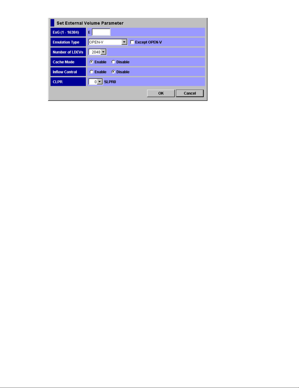
Figure 33 Set External Volume Parameter Dialog Box
The Set External Volume Parameter dialog box consists of:
• ExG (1 -163 84 )
Group numbe
numbers fro
r of the connected external volume. You need to specify the number using decimal
m1to 16384. E displayed outside of the text box is the capital letter of the external
volume group.
• Emulation Type
You can sel
ect the emulation type of the mapped external volume from the drop-down list.
To map the external volume as an open system volume, you need to first decide the emulation type
for the mapped volume, OPEN-V or other than OPEN-V. To map the external volume as an open
system vol
ume with the emulation type other than OPEN-V, select the Except OPEN-V check box.
•As you clear the Except OPEN-V check box, OPEN-V and available mainframe emulation
types are displayed in the drop-down list.
•As you sel
ect the Except OPEN-V check box, the emulation types for the open system other
than OPEN-V are also displayed in the drop-down list.
• Number of LDEVs
You can se
lect the maximum number of LDEVs which can be created in the external volume when
you map the external volume. The number of LDEVs that can be created in the external volume is
different corresponding to the capacity supported by the emulation type specified in the Emulation
Type. The number of LDEVs which are actually created in the external volume is displayed in
the Numb
er of LDEVs column in the Add Volume dialog box after you set this parameter in the
Set External Volume Parameter dialog box.
• Cache mode
Cache mo
de specifies if the write I/O from the host is propagated synchronously (Disable)or
asynchronously (Enable)tothe External Storagedevice.
Caution:
If you set Disable, the bind mode of Cache Residency Manager cannot be set.
• Inflow Control
Inflow Co
ntrol specifies if the writing operation to the cache memory is stopped (Enable)or
continued (Disable) when the writing operation to the external volume is impossible.
• CLPR
When th
for acc
that se
emula
e cache memory is partitioned using Disk/Cache Partition, you can select CLPR used
essing to the mapped external volume from the drop-down list. The number of SLPR
lected CLPR belongs is displayed at the right of the drop-down list. However, when the
tion type for the mainframe is selected in Emulation Type, you can only select CLPR that
belongs to SLPR number 0.
• OK button
the settings and closes the dialog box.
Saves
• Cancel button
Cancels the settings and closes the dialog box.
XP24000 External Storage Software User’s Guide
73
Page 74

LDEV Mapping (Au
to) Dialog Box
The LDEV Mappin
the external vo
are automatically assigned for the rest of LDEVs.
g (Auto) dialog box allows you to specify the LDEV number only to the first LDEV in
lume. If you specify the LDEV number to the firstLDEV, thesubsequentLDEVnumbers
Figure 34 LDEV Mapping (Auto) Dialog Box
The LDEV Mapping (Auto) dialog box consists of:
• SLPR Limited
To restrict the CU in the CU drop-downlisttothe CU whichbelongs to theSLPR, select the Limited.
To display all the CU in the CU drop-down list without any restriction, select the Unlimited.By
default, the Limited is selected.
• LDKC drop-down list
You can select the LDKC number of the local storage system to which you want to map the
external volume.
• CU drop-down list
You can select the CU number of the local storage system to which you want to map the external
volume. When you select Limited in the SLPR Limited, the selection range is limited to CU which
belongs to the SLPR.
• Interval drop-down list
You can select the interval of the LDKC:CU:LDEV number for mapping each volume. The LDEV
number is settoeachLDEVwiththe interval that youspecified in this drop-down list.
• LDEV Map
LDEV map allows you to allocate the LDEV number to each LDEV by clicking cells in a table.
Each cell in the LDEV map represents an internal volume. In the LDEV map, the horizontal scale
indicates tens place digit of the LDEV number, and the vertical scale indicates ones place digit of
74
Performing External Storage Operations
Page 75

the LDEV number. Select a cell for the internal volume on the LDEV map, the selected cell turns to
blue, and the LDEV number which the cell indicates is defined to the LDEV. The defined internal
volume is grayed out, and undefined internal volumes to be mapped are displayed in white.
• OK button
Saves the settings and closes the dialog box.
• Cancel button
Cancels the settings and closes the dialog box.
• Pop-up menu
This dialog box does not have a pop-up menu that can be displayed.
LDEV Mapping (Manual) Dialog Box
The LDEV Mapping (Manual) dialog box allows you to specify the LDEV number to all the LDEVs in the
external volume.
Figure 35 LDEV Mapping (Manual) Dialog Box
The LDEV Mapping (Manual) dialog box consists of:
• List
• ExG
The external volume group number of the connected external volume, which you specified in
the Set External Volume Parameter dialog box, is displayed.
• LDKC:CU:LDEV
You use the LDKC:CU:LDEV with the LDEV map for assigning the LDEV number. You can either
map an LDEV number to each LDEV one by one, or map a numbers to multiple LDEVs at once.
The LDKC:CU:LDEV shows the LDKC numbers, CU numbers, and LDEV numbers of the external
volumesmappedasinternalvolumes. A hyphen (-) indicates that the external volumes are
not mapped as internal volumes.
To assign an LDEV number to an LDEV, select one or more external volume whose LDEV
number is a hyphen (-) in the LDKC:CU:LDEV, and select one cell in the LDEV map.
XP24000 External Storage Software User’s Guide
75
Page 76

When you select two or more external volumes in the LDKC:CU:LDEV, the other cells are
automatically added to match the number of external volumes that you previously selected in
the LDKC:CU:LDEV.When Interval is set, mapping is performed in intervals of that number.
• Pop-up menu
This dialog box does not have a pop-up menu that can be displayed.
Other items are same as the LDEV Mapping (Auto) dialog box. For details, see
“LDEV Mapping(Auto)DialogBox”onpage74.
SSID Dialog Box
The SSID dialo
assigns a SSI
SSID, you need to assign one using the SSID dialog box. The SSID dialog box is displayed during the
mapping operation when the SSID setting is required.
Figure 36 SSID Dialog Box
The SSID dialog box consists of:
g box allows you to set the SSID to the LDEVs in the external volume. The storage system
D which identifies each group of LDEV number. If the LDEVs that you created do not have
• SLPR drop-down list
When the storage system is partitioned using Disk/Cache Partition, use the SLPR drop-down list.
If you select the SLPR Limited check box and select the SLPR number in the SLPR drop-down list,
only the SSIDs that can be used for the selected SLPR can be set in the Set SSID dialog box. If
you do not select the SLPR Limited check box, you can set the SSID from all the unused SSIDs
regardless of the selected SLPR number.
• List
• LDEV Boundary
The range of LDEVs in the selected external volume is displayed.
• SSID
The SSIDs allocated to each LDEV are displayed. If SSID is not set, a hyphen (-) is displayed.
• OK button
Saves the settings and closes the dialog box.
• Cancel button
Cancels the settings and closes the dialog box.
• Pop-up Menu
Right-click a row in the SSID column to execute the Set SSID command in the pop-up menu. The
Set SSID command allows you to set the SSID to the selected LDEV. When you click the Set
SSID, the following dialog box is displayed.
76
Performing External Storage Operations
Page 77

Figure 37 Set SSID Dialog Box
SSID (0004–FFFE):Selectthe SSID from theSSIDdrop-down list. You canselect the valuefor
an SSID from 0x0004 to 0xFFFE.
• If you have selected the SLPR Limited check box on the SSID dialog box, only the SSIDs that
can be used in SLPR selected on the SSID dialog box are displayed in the drop-down list.
• If you have not selected the SLPR Limited check box on the SSID dialog box, all of the unused
SSIDs are displayed in the drop-down list regardless of the selected SLPR.
Example: How to Map LDEVs Automatically
For instance, you map two external volumes which have the same emulation type, and create two
LDEVs in each external volume.
To assign the number which starts 00:01:01 with 255 intervals to total four LDEVs that you created:
1. Select the two external volumes and right-click them in the Add Volume dialog box, and then
click the LDEV Mapping (Auto) in the pop-up menu.
The LDEV Mapping (Auto) dialog box is displayed.
2. Configure the starting LDEV number and interval as follows:
•LDKC: 00
•CU: 01
•Interval: 255
• LDEV map: Select the cell in the row 1 and column 00.
3. Click OK.
LDEV numbers are automatically assigned as follows:
•the first LDEV: 00:01:01
• the second LDEV: 00:02:01
• the third LDEV: 00:03:01
• the fourth LDEV: 00:04:01
However, the Add Volume dialog box displays only the LDEV number assigned for the first
LDEV of each external volume. In this case, 00:01:01... and 00:03:01... are displayed in the
Add Volume dialog box.
Example: How to Map LDEVs Manually
For instance, you map two external volumes which have the same emulation type, and create two
LDEVs in each external volume.
To assign the desired number to total four LDEVs that you created:
1. Select the two external volumes and right-click them in the Add Volume dialog box, and then
click the LDEV Mapping (Manual) in the pop-up menu.
The LDEV Mapping (Manual) dialog box is displayed.
2. Click the LDEV to which you want to assign an LDEV number in the LDKC:CU:LDEV column on the
left of the LDEV Mapping (Manual) dialog box.
3. Select the desired LDKC number and the desired CU number to the specified LDEV from the
drop-downlistonthe rightofthe LDEV Mapping(Manual)dialogbox.
4. Click the cell of the desired LDEV number in the LDEV map on the right of the LDEV Mapping
(Manual) dialog box (see Figure 38 on page 78).
The selected cell turns blue and the assigned LDEV number is displayed in the LDKC:CU:LDEV
column.
XP24000 External Storage Software User’s Guide
77
Page 78

5. Make the settings to all the LDEVs in the LDKC:CU:LDEV column (repeat step 2 through step 4).
6. Click OK.
The specified numbers are assigned to the LDEVs. However, the Add Volume dialog box displays
only the LDEV number assigned for the fi rst LDEV of each external volume.
Figure 38 Example of LDEV Mapping (Manual) Dialog Box
Note:
You can also assign contiguous LDEV numbers to LDEVs using this dialog box. To assign
contiguous LDEV numbers to LDEVs, select multiple LDEVs at step 2, and specify the starting LDEV number
at step 3 and 4.You can set Interval if necessary.
Settin
g the Cross-subsystem Paths
You nee
using the external volume mapped as an internal volume. For details on the cross-subsystem path, see
“Cross-subsystem Paths”onpage23.
You can configure the cross-subsystem path when you map the external volume as the internal volume.
You can also add or change the cross-subsystem paths after the mapping operation is completed. To
configure the cross-subsystem paths, use the Configure Cross-subsystem Paths dialog box.
dtoconfigure the cross-subsystem path from the internal volume to the external volume before
Configure Cross-subsystem Paths Dialog Box
The Configure Cross-subsystem Paths dialog box allows you to configure cross-subsystem paths. This
dialog box is automatically displayed when you add a volume to a new path group using the Add
Volume (Auto) command or the Add Volume (Manual) command. You can also open this dialog box by
clicking the Configure Cross-subsystem Paths command in the Volume Operation window.
78
Performing External Storage Operations
Page 79

You can change the priority, add and delete the cross-subsystem path in the Configure Cross-subsystem
Paths dialog box.
The Volume Operation window displays only the external storage system which you have configured the
mapping. However, the Configure Cross-subsystem Paths dialog box displays all the external storage
system connected to the local storage system even without the mapping configuration. To update the
dialog box, click the Port Discovery button in the upper right of the dialog box.
Figure 39 Configure Cross-subsystem Paths Dialog Box
The Configure Cross-subsystem Paths dialog box consists of:
• Available Paths (Upper part of the dialog box)
The following three panes are displayed from the left,
•The left
pane displays the external storage systems connected to the local storage system.
• Vendor: vendor name.
• Product Name:product name.
• Serial
Number: serial number of the product.
• The middle pane displays external ports of the local storage system, which connects to the
external storage system that you clicked in the left pane. One of the following icons is
displayed for each port:
• Port: external port of the local storage system.
•The r
ight pane displays WWN of the external storage system that the port attribute is set to
Target. The WWN which connects to the port that you clicked in the middle pane is displayed
outofthe WWN ofthe external storagesystem which youclicked in theleftpane.
• WWN:Identification number of the port in the external storage system.
tDiscovery button (Upper right of the dialog box)
• Por
ows you to update information displayed in the Available Paths or display the information on
All
all the external storage system connected to the local storage system even without the mapping
configuration. When you click Port Discovery, the Port Discovery dialog box is displayed.
XP24000 External Storage Software User’s Guide
79
Page 80

Figure 40 Port Discovery Dialog Box
The Port Discovery dialog box displays the list of the external ports in the local storage system.
When you click the external port in the list, WWNs of the external storage system connected
to the clicked external port are searched for, and that the Available Paths in the Configure
Cross-sub
system Paths dialog box is updated.
• Selected Paths (Lower part of the dialog box)
The cross-subsystem paths that you have added in the Available Paths are displayed.
• Priority:
Priority of the cross-subsystem paths connecting to the external volume. 1 indicates
thepathwiththe highestpriority.
• Port: Port of the local storage system that the port attribute is set to External.
• WWN:WWN o
f the external storage system that the port attribute is set to Target.
• OK button
Saves the settings and closes the dialog box.
• Cancel bu
tton
Cancels the settings and closes the dialog box.
• Pop-up Menu
ick a row in the Configure Cross-subsystem Paths dialog box to perform the following
Right-cl
operati
ons from the pop-up menu.
Table 16 Pop-up Menu in the Configure Cross-subsystem Paths dialog box
licked Area
Right-c
WWN in the
Available Paths
ed Paths
Select
80
Performing External Storage Operations
Pop-up menu
Add
Delete
Raise Priority
Lower Priority
Reference
Section Configuring
Cross-subsystem Path
on page81.
Section Canceling
the Cross-subsystem
Path Configuration on
page 83.
Section Changing
the Configured
Cross-subsystem Path
Priority on page 82.
Descrip
Allows you to add
cross-subsystem paths.
Allows you to delete the selected
cross-subsystem path.
Allows you to raise the priority
of the selected cross-subsystem
path.
Allows you to lower the priority
of the selected cross-subsystem
path.
tion
Page 81

Configuring Cros
s-subsystem Path
You can configur
section explains the procedure to add a cross-subsystem path to an existing path group. To create a new
path group and configure cross-subsystem paths, you need to operate the mapping operation. For the
procedure, see “Mapping an External Volume Automatically” on page 69.
To add the cross
1. Start Remote Web Console, and open the Volume Operation window.
2. Make sure that Remote Web Console is in Modify mode.
3. Click the path
4. Right-click the cross-subsystem path in Cross-subsystem Paths in theVolumeOperation list.
Apop-up menuis displayed.
5. Click Configu
The Configure
“Configure Cr
6. In the Avail
WWN (see Figure 41 on page 82).
• External storage system: Click the external storage system.
• Port:Clic
cross-subsystem path.
• WWN: Click the WWN of the external storage system which is the ending point of the
cross-sub
Note:
in the dialog box, you can update the information by clicking the Port Discovery button, selecting
the port which connects to the WWN, and then clicking OK.
Apop-up m
7. Click Add in the pop-up menu.
The cross-subsystem path is added to the Selected Paths with the selected information. Configure
more than two cross-subsystem paths for one path group. Change the priority or delete
unnecessary cross-subsystem paths if necessary.
8. Click OK
You are returned to the Volume Operation window. The settings are displayed in blue and italics.
9. Verify the settings in the Preview dialog box (see “Preview Dialog Box” on page 57).
10. Click Apply in theVolumeOperation window.
The sett
displa
in the Preview dialog box.
e the cross-subsystem path using the Configure Cross-subsystem Paths dialog box. This
-subsystem path to an existing path group:
group that you want to add a cross-subsystem path in the Volume Operation tree.
re Cross-subsystem Paths in the pop-up menu.
Cross-subsystem Paths dialog box is displayed (see
oss-subsystem Paths Dialog Box”onpage78).
able Paths, click the following three items, and then right-click the WWN in the
k the external port of the local storage system which is the starting point of the
system path.
When the external storage system or the WWN that you want to choose is not displayed
enu is displayed.
to close the Configure Cross-subsystem Paths dialog box.
ings are applied to the local storage system and the Volume Operation window is
yed normally. When an error occurs, an error message is displayed. Verify the details
XP24000 External Storage Software User’s Guide
81
Page 82

Figure 41 Pop-up Menu of Configure Cross-subsystem Paths Dialog Box
Changing the Configured Cross-subsystem Path Priority
To change
command d
The follo
raising
1. Start Remote Web Console, and open the Volume Operation window.
2. Make sure that Remote Web Console is in Modify mode.
3. Click t
4. Right-click the cross-subsystem path in Cross-subsystem Paths in the Volume Operation list.
5. Click C
6. Right
7. Click Raise Priority in the pop-up menu
8. Repeat the operation of the Raise Priority command until the row of the selected path is
9. Click OK to close the Configure Cross-subsystem Paths dialog box.
10. Veri
11 . Click Apply in theVolumeOperation window.
the cross-subsystem path priority, use the Raise Priority command and the Lower Priority
isplayed in the Configure Cross-subsystem Paths dialog box.
wing is an example of procedure to make the cross-subsystem path to the currently used path by
the priority of the cross-subsystem path:
he path group to which the cross-subsystem path belongs in the Volume Operation tree.
Apop-upmenuisdisplayed.
onfigure Cross-subsystem Paths in the pop-up menu.
The Con
“Config
in the
Apop-upmenuisdisplayed.
The ro
displayed in the head of the Selected Paths list and its Priority column changes to 1.
When t
used one (primary path).
You a
The settings are applied to the local storage system and the Volume Operation window is
displayed normally. When an error occurs, an error message is displayed. Verify the details
in t
figure Cross-subsystem Paths dialog box is displayed (see
ure Cross-subsystem Paths Dialog Box” on page 78).
-click the cross-subsystem path that you want to change the priority of in the Selected Paths
Configure Cross-subsystem Paths dialog box.
w of the selected path switches with the one row above.
he Priority column changes to 1, it means the cross-subsystem path is set as the usually
re returned to the Volume Operation window. The settings are displayed in blue and italics.
fy the settings in the Preview dialog box (see “Preview Dialog Box”onpage57).
he Preview dialog box.
82
Performing External Storage Operations
Page 83

Canceling the Cr
oss-subsystem Path Configuration
You can cancel t
dialog box.
To cancel the cross-subsystem path configuration:
1. Start Remote Web Console, and open the Volume Operation window.
2. Make sure that R
3. Click the path group to which the cross-subsystem path belongs in the Volume Operation tree.
4. Right-click the cross-subsystem path in Cross-subsystem Paths in theVolumeOperation list.
Apop-up menui
5. Click Configure Cross-subsystem Paths in the pop-up menu.
The Configure Cross-subsystem Paths dialog box is displayed (see
“Configure Cross-subsystem Paths Dialog Box”onpage78).
6. Right-click the cross-subsystem path that you want to cancel the configuration in the Selected
Paths in the Configure Cross-subsystem Paths dialog box.
Apop-up menuis displayed.
7. Click Delet
The configuration of the selected cross-subsystem path is canceled, and the cross-subsystem path
is deleted from the Cross-subsystem Paths.
8. Click OK to close the Configure Cross-subsystem Paths dialog box.
You are retu
9. Verify the
10. Click Apply in theVolumeOperation window.
The settings are applied to the local storage system and the Volume Operation window is
displayed normally. When an error occurs, an error message is displayed. Verify the details
in the Prev
he configuration of the cross-subsystem path using the Configure Cross-subsystem Paths
emote Web Console is in Modify mode.
sdisplayed.
e in the pop-up menu
rned to the Volume Operation window. The settings are displayed in blue and italics.
settings in the Preview dialog box (see “Preview Dialog Box” on page 57).
iew dialog box.
Changing the Cross-subsystem Path
To change the cross-subsystem path, cancel the current cross-subsystem path, and configure another
cross-subsystem path as a new cross-subsystem path. For how to cancel the current cross-subsystem
path, see “Canceling the Cross-subsystem Path Configuration” on page 83 For how to configure an
cross-subsystem path, see “Configuring Cross-subsystem Path”onpage81.
Checkin
g the External Volume Details
You can c
the deta
To check the external volume details:
1. Start Remote Web Console, and open the Volume Operation window.
2. Click t
3. Right-click the external volume that you want to check in the Volume Operation list.
4. Click t
5. Verify the details in the displayed dialog box.
6. Clic
heck the details on the mapped external volume using the LDEV Information dialog box, and
ils on the mapping path using the Mapping Path Information dialog box.
he path group in the Volume Operation tree.
Apop-up menuis displayed.
he following command in the pop-up menu.
• LDEV information: Displays the LDEV Information dialog box (section
“LDEV Information Dialog Box”onpage84).
• Mapping Path Information: Displays the Mapping Path Information dialog box (section
“Mapping Path Information Dialog Box”onpage84).
k Close to close the displayed dialog box.
You are returned to the Volume Operation window.
XP24000 External Storage Software User’s Guide
83
Page 84
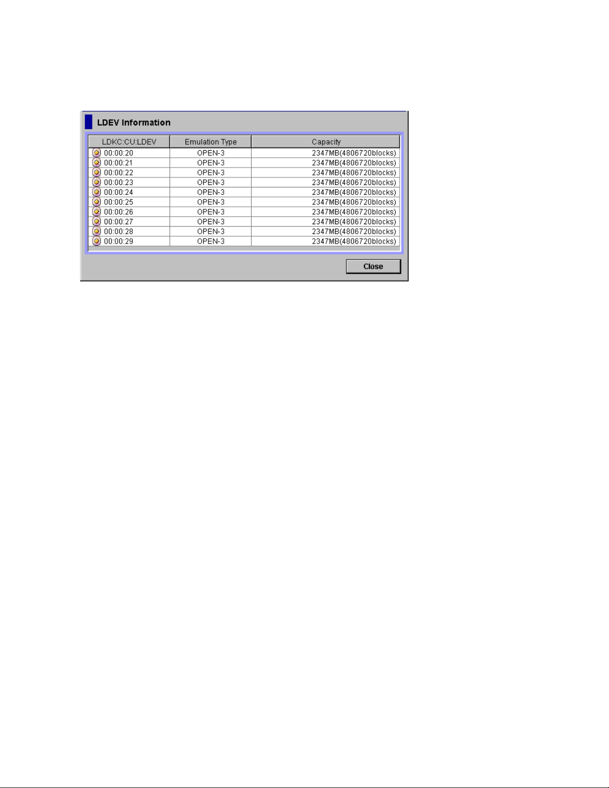
LDEV Information Dialog Box
The LDEV Information dialog box displays the information on the LDEVs created in the external volumes.
Each row displays one LDEV information.
Figure 42 LDEV Information Dialog Box
The LDEV Information dialog box consists of:
• List
• LDKC:CU:LDEV: The LDKC:CU:LDEV number of the LDEVs created in the external volume.
• Emulation Type: The emulation type of the external volume set when it was mapped.
• Capacity: Capacity of the external volume is displayed. When the emulation type of the
mapped external volume is for the open system, the capacity is displayed in Blocks. When
the emulation type of the mapped external volume is for the mainframe system, the capacity
is displayed in Cylinder.
• Close button
Closes the LDEV Information dialog box.
• Pop-up menu
The LDEV Information dialog box does not have a pop-up menu that can be displayed.
Mapping Path Information Dialog Box
The Mapping Path Information dialog box displays the information on the mapping paths which connect
the inter
84
nal volume and the external volume.
Performing External Storage Operations
Page 85

Figure 43 Mapping Path Information Dialog Box
The Mapping Path Information dialog box consists of:
• List
• Priority: Priority of the mapping path. 1 indicates the mapping path with the highest priority.
• Port: The port number in the local storage system connecting to the external storage system.
• WWN:Identification number of the port in the external storage system.
• LUN: LU number set to the external volume.
• Status: Status of the mapping path. One of the following statuses is displayed. For how to
react to the displayed status, see “Troubleshooting for External Storage” on page 107.
XP24000 External Storage Software User’s Guide
85
Page 86

Table 17 Status of the Mapping Paths in the Mapping Path Information Dialog
Box
Displayed Item
Normal The mapping path is normal.
-
Unknown
Blockade The mapping path is blocked.
External device
setting changed
LDEV size reduced
Not ready
Illegal request Thereply of theexternalstorage system was ILLEGALREQUEST.
Command aborted
Busy
LDEV reserved The external storage system is in the Reserve status.
Response error
Initiator port
Description
The status of the mapping path is not retrieved yet. Click Status in the Volume
Operation window to display the status of the mapping path.
The statusofthe mappingpathisunknown.
The setting of the external storage system has been changed. For example, the
path definition was deleted, or the external storage system itself was replaced
by another device.
Thesetting of thevolumecapacityofthe external storagesystemhas been
changed (the volume capacity was reduced).
The reply of the external storage system was NOTREADY.
Thereply of theexternalstorage system was ABORTEDCOMMAND.
The external storage system is in the BUSY status.
The external storage system is in the blocked status caused by the abnormal
reply (Response).
The port attribute of the external storage system has been changed to the
initiator port.
Unknown port
Cannot detect port
Internal error The program error occurred. Or there is a logical contradiction.
Timeout
Standby
Target error
Checking
Disconnect
Unavailable
Backoff
The port attribute of the external storage system is unknown.
The path has been removed or the port of the external storage system cannot
be found.
The processing was retried because the abnormal reply (Response) was
returned, however, the processing has been stopped by timeout.
The port of the external storage system is standing by. The port status is normal
but cannot receive I/O.
Port failures, such as controller blockade are detected on the external storage
system side.
The processing of checking the mapping path status is in progress.
Connecting to the external storage system or the external volume is intentionally
stopped using the Disconnect Subsystem command or the Disconnect Volume
command.
The reply of the external storage system was Unavailable. The external storage
system demands to change the connected port. Once the status becomes
Unavailable, the primary path is changed to the alternate path that is in the
Standby status. When the primary path has been changed, the status of the
path becomes Normal.
The reply of the external storage system was Backoff. The status of the path is
waiting for recovery because a temporary error has occurred in the volume of
the external storage system. Even if the status of the primary path becomes this
status, the primary path is not changed to the alternate path immediately. After
the error recovery, the status becomes Normal. If the status cannot be recovered
from the error, the path status is changed to the other status.
86
Performing External Storage Operations
Page 87

• Close button
Close the Mapping Path Information dialog box.
• Pop-up menu
The Mapping Path Information dialog box does not have a pop-up menu that can be displayed.
Turning On or Of
This section de
system after th
This section e
• Turning on or off the power supply of only external storage system (see
“Turning On or Off Only the External Storage System” on page 88).
• Turning on or off the power supply of only local storage system (see
“Turning On or Off Only the Local Storage System” on page 88).
• Turning on or
“Turning On
This section explains taking the case where Business Copy is used as an example.
When you turn on or off the power supply of only external storage system, you need
to execute the External Storage commands. For details on these commands, see
“Commands for Turning On or Off Only the External Storage System” on page 87.
Caution:
first need turn off the local storage system, and then turn off the external storage system.
Caution:
first need t
e External Storage operation has been started.
xplainsasfollows:
When you want to turn off both the local storage system and the external storage system, you
hen you want to turn on both the local storage system and the external storage system, you
W
oturnonthe external storagesystem, andthenturnonthe localstorage system.
f the Storage System
scribes the procedure to turn on or off the local storage system and the external storage
offthe powersupplyofbothstorage systems(see
or Off Both Storage Systems”onpage89).
Commands for Turning On or Off Only the External Storage System
When you turn on or off the power supply of only external storage system while the power supply of the
local storage system keeps on, you need to execute the following External Storage commands.
Thecommandsusedfor theprocedure areasfollows:
• Disconnect Subsystem command
The Disconnect Subsystem command should be executed when the external storage system is
maintained or stopped on purpose. When the Disconnect Subsystem command is executed, the
acceptance of the host I/O to the external volume that is mapped as the internal volume is
stopped. Then all the data that should belong to the external volume is written to the external
volume from the cache memory of the local storage system (all the data is destaged).
For the procedure to execute the Disconnect Subsystem command, see
“Disconnecting External Storage System or Disconnecting External Volume” on page 89.
Note:
When you want to perform the same processing of the Disconnect Subsystem command
on individual volume, you can use the Disconnect Volume command. To delete the external
volume mapping individually, you first need to execute the Disconnect Volume command and
then the Delete Volume command. For the procedure to delete the external volume mapping, see
“Deleting the External Volume Mapping” on page 96.
• Check Paths & Restore Volume command
The Check Paths & Restore Volume command checks if the defined information about the mapped
external volume and the actual external volume status match. If the external volume can be used
as the mapped volume as the result of the check, the external volume is set to accept the I/Os,
and you can continue using the external volume as a mapped volume.
The Check Paths & Restore Volume command can be used to restore the external volume, which
is set to reject the host I/O by the Disconnect Subsystem command or the Disconnect Volume
command, as the mapped volume. The Check Paths & Restore Volume command can be executed
for both the whole storage system and for the individual volume.
If an error occurs in the path, fi rstly remove the error in the path to make the path restorable,
and then execute the Check Paths & Restore Volume command.
XP24000 External Storage Software User’s Guide
87
Page 88

For the procedure to execute the Check Paths & Restore Volume command, see
“Checking Connection Status and Resuming External Volume Operation” on page 91.
Note:
When the Check Paths & Restore Volume command is executed and the external volume is
ready to be restored as the mapped volume, the external volume is set to accept the I/Os and
you can resume using the external volume as a mapped volume. However, if the external volume
is not ready to be restored, the external volume status remains blocked.
Turning On or Off Only the External Storage System
• To turn off the
1. Stop the read
internal vol
2. Execute the
to turn off.
The additional I/O to the external volume is stopped and all the data in the local cache memory
is written in the external volume (all the data is destaged).
For the proc
“Disconnecting External Storage System or Disconnecting External Volume” on page 89.
3. Perform other operations that are required before turning off the local storage system, if there is
some.
4. Turn off th
power supply of the external storage system (to turn off on purpose):
or write I/O to the external volume that is mapped as a local storage system
ume and is contained in the external storage system that you want to turn off.
Disconnect Subsystem command for the external storage system that you want
edure to execute the Disconnect Subsystem command, see
e power supply of the external storage system.
Caution:
external volume again, execute the Check Paths & Restore Volume command.
• To turn on the power supply of the external storage system to restart from the turned off status:
1. Turn on th
2. Execute the Check Paths & Restore Volume command of the External Storage.
Caution:
executed, you cannot access the mapped external volume from the local storage system as you just turn
the external storage system on. It is necessary to execute the Check Paths & Restore Volume command to
resume u
defined
external volume is ready to be used as a mapped volume, the volume is set to accept the I/Os and you
can resume using the volume as a mapped volume.
fter you have executed the Disconnect Subsystem command, but you need to use the mapped
A
e external storage system that contains the external volume, which is mapped as
an internal volume.
For the pr
“Checking Connection Status and Resuming External Volume Operation” on page 91.
ocedure to execute the Check Paths & Restore Volume command, see
When the external storage system is turned off after the Disconnect Subsystem command is
sing the mapped external volume. The Check Paths & Restore Volume command checks the
information and the actual status of the external volume mapped as an internal volume. If the
Turning On or Off Only the Local Storage System
• To turn off the power supply of the local storage system (to turn off on purpose):
1. Stop the read or write I/O to the external volume that is mapped as a local storage system
internal volume.
2. Perform other operations that are required before turning off the local storage system, if there is
some.
3. Turn off the power supply of the local storage system.
Note:
As you turn off the power supply of the local storage system, all the data, which is for the external
volume, in the local cache memory is written in the external volume (all the data is destaged).
• To turn on the power supply of the local storage system to restart from the turned off status:
1. Turn on the external storage system that contains the external volume, which is mapped as
an internal volume.
2. Turn on the power supply of the local storage system.
Caution:
executed, you cannot access the mapped external volume from the local storage system as you just turn
88
When the local storage system is turned off after the Disconnect Subsystem command is
Performing External Storage Operations
Page 89

the local storage system on. It is necessary to execute the Check Paths & Restore Volume command to
resume using the mapped external volume. The Check Paths & Restore Volume command checks if the
defined information and the actual status of the external volume mapped as an internal volume match. If
the external volume is ready to be used as a mapped volume, the volume is set to accept the I/Os and
you can resume using the volume as a mapped volume.
Caution:
all the data in the cache memory is written to the external volume, the displayed information for Ext.
VOL Status in theVolumeOperation window becomes Disconnect.
When the Disconnect Subsystem command or the Disconnect Volume command is executed and
Turning On or Off Both Storage Systems
This section explains how to turn on or off the power supply of both the local storage system and the
external storage system taking the case where Business Copy is used as an example.
• To turn off th
1. Stop the rea
All read and
2. Split all Business Copy pairs (pairsplit operation).
For details on the pairsplit operation, see the HP StorageWorks XP24000 Business Copy
Software User’s Guide.
3. Turn off th
Caution:
then go on to the next step.
4. Turn off the power supply of the external storage system.
Caution:
• To turn on the power supply of both storage systems:
1. Turn on the power supply of the external storage system.
Caution:
then go o
2. Turn on t
Caution
then go on to the next step.
3. Resynchronize all Business Copy pairs (pairresync operations).
For deta
Softwa
4. Start the read or write I/O to the local storage system.
All read and write I/Os with Fibre Channel connections should be started.
e power supply of both storage systems:
d or write I/O to the local storage system.
write I/Os with Fibre Channel connections should be stopped.
e power supply of the local storage system.
ake sure that the power supply of the local storage system is completely off and
M
Make sure that the power supply of the external storage system is completely off.
Make sure that the power supply of the external storage system is completely on and
n to the next step.
he power supply of the local storage system.
:
Make sure that the power supply of the local storage system is completely on and
ils on the pairresync operation, see the HP StorageWorks XP24000 Business Copy
re User’s Guide.
Disconnecting External Storage System or Disconnecting
External Volume
The Disconnect Subsystem command and the Disconnect Volume command allow you to disconnect the
external volume. You need to disconnect the external volume(s), for example, before you turn the power
supply off of the local storage system or the external storage system for maintenance, or before you
delete the external volume mapping.
As you execute the Disconnect Subsystem command or the Disconnect Volume command, the acceptance
of the host I/O to the mapped external volume is stopped and all the data in the cache memory is written
into the external volume (all the data is destaged).
The settings of the mapping are preserved, even though the external volume is disconnected using
the Disconnect Subsystem command or the Disconnect Volume command. Therefore, you can resume
using the external volume as a mapped volume with the former settings, even though once you have
disconnected the external volume. For the procedure to resume using the disconnected external volume,
see “Checking Connection Status and Resuming External Volume Operation” on page 91.
XP24000 External Storage Software User’s Guide
89
Page 90

Caution:
as follows:
• After you have executed the Disconnect Subsystem command or the Disconnect Volume command,
• If you execute the Disconnect Subsystem command or the Disconnect Volume command when
• If thevolumeisonlinefromthe mainframehost, the Disconnect Subsystem command or the
• The Disconnect Subsystem command or the Disconnect Volume command cannot be executed
• The Disconnect Subsystem command or the Disconnect Volume command cannot be executed
• When the Disconnect Subsystem command or the Disconnect Volume command is executed, the
• When the Disconnect Subsystem command or the Disconnect Volume command is executed and
The cautions on the Disconnect Subsystem command and the Disconnect Volume command are
click the Refresh command (
information,
I/Os from theopensystem hostare in progress,the host I/Os to thespecified volume are forcibly
stopped. When
command, stop the host I/Os and unmount from the host.
Disconnect V
the Vary Offline operation.
for externa
Continuous
for Mainframe, or XP Snapshot. However, if the pair status is PSUE, these commands can be
executed. When the external volume is set as a pool volume (pool-VOL) and the status of that
XP Snapsho
for external volumes including the LDEVs for which the migration processing of Auto LUN is in
progress.
displayed information for Ext. VOL Status in theVolumeOperation window becomes Cache
Destage.
Cache De
Volume command has been completed.
all the d
Ext. VOL Status in theVolumeOperation window becomes Disconnect.
and check the current progress status.
you execute the Disconnect Subsystem command or the Disconnect Volume
olume command cannot be executed. Stop the host I/Os to the volume and perform
l volumes that are set as the pair of Business Copy, ShadowImage for Mainframe,
Access Journal, Universal Replicator for Mainframe, Continuous Access, TrueCopy
t pair is PAIR, these commands can be executed.
Even if there is no data left in the cache memory, the displayed status remains as
stage, until the processing of the Disconnect Subsystem command or the Disconnect
ata in the cache memory is written to the external volume, the displayed information for
) on the Remote Web Console main window to update the
Disconnecting All External Volumes (Disconnect Subsystem)
To disconnect all the external volumes in the external storage system at once:
1. Start Remote Web Console, and open the Volume Operation window.
2. Make sure that Remote Web Console is in Modify mode.
3. Right-clickthe productnamethatyou want to disconnect in theVolumeOperation tree.
Apop-upmenuisdisplayed.
4. Click Disconnect Subsystem in the pop-up menu.
The settings are displayed in blue and italics.
5. Verify the settings in the Preview dialog box (see “Preview Dialog Box”onpage57).
6. Click Apply in theVolumeOperation window.
The settings are applied to the local storage system and the Volume Operation window is
displayed normally. When an error occurs, an error message is displayed. Verify the details
in the Preview dialog box.
Caution:
command, you need to execute the Check Paths & Restore Volume command.
onnecting an Individual External Volume (Disconnect Volume)
Disc
To disconnect an individual external volume:
1. Start Remote Web Console, and open the Volume Operation window.
2. Mak
3. Click the product name in the Volume Operation tree.
4. Right-click the external volume that you want to change in the Volume Operation list.
To access the external storage system after you have executed the Disconnect Subsystem
esure thatRemoteWeb ConsoleisinModifymode.
90
Performing External Storage Operations
Page 91

Apop-up menuis displayed.
5. Click Disconnect Volume in the pop-up menu.
The settings are displayed in blue and italics.
6. Verify the settings in the Preview dialog box (see “Preview Dialog Box” on page 57).
7. Click Apply in theVolumeOperation window.
The settings are applied to the local storage system and the Volume Operation window is
displayed normally. When an error occurs, an error message is displayed. Verify the details
in the Preview dialog box.
Caution:
command, you need to execute the Check Paths & Restore Volume command.
To access the external storage system after you have executed the Disconnect Volume
Checking Con
Operation
You can resume external volume operation by executing the Check Paths & Restore Volume command
in the following cases:
• The Check Paths & Restore Volume command is required to be executed to resume using the
disconnect
Volume command.
• When the errors occur in all the cross-subsystem paths, the local storage system makes the status of
external v
If the status of the external volume cannot be restored even though the Check Paths & Restore
Volume command is executed, see “Troubleshooting for External Storage”onpage107 and
restore the path to the external storage system according to the procedure of the troubleshooting.
Then execute the Check Paths & Restore Volume command to make the external volume in the
Blockade
• When the Check Paths & Restore Volume command is executed for the disconnected external
volume for which the mapping settings are preserved, the defined mapping setting and the
current status of the external volume are compared and checked if the settings match the actual
status. The path status and all other mapping configuration definitions are checked. If the external
volume can be resumed as a mapped volume as a result of the checking processing, the volume
status is setto beavailablefor theI/O operation.
Cautio
and then the Refresh command (
and check the current progress status.
Note:
to be restored as the mapped volume, the external volume is set to accept the I/Os and you can resume
using the external volume as a mapped volume. However, if the external volume is not ready to be
resumed, the status of the disconnected volume remains as Blockade.
olume to Blockade. In this case, execute the Check Paths & Restore Volume command.
n:
After you have executed the Check Paths & Restore Volume command, click the Status button
When the Check Paths & Restore Volume command is executed and the external volume is ready
nection Status and Resuming External Volume
ed external volume using the Disconnect Subsystem command or the Disconnect
status usable.
) on the Remote Web Console main window to update the information,
Resuming All External Volumes (Check Paths & Restore Volume)
sume all the external volumes in the external storage system at once:
To re
1. Start Remote Web Console, and open the Volume Operation window.
2. Make sure that Remote Web Console is in Modify mode.
3. Rig
4. Click Check Paths & Restore Volume in the pop-up menu.
5. Ver
6. Click Apply in theVolumeOperation window.
ht-click the product name that you want to resume connection in the Volume Operation tree.
Apop-up menuis displayed.
ettings are displayed in blue and italics.
The s
ify the settings in the Preview dialog box (see “Preview Dialog Box” on page 57).
The Ext. VOL Status in the Volume Operation window changes to Checking. When the checking
processing of mapping path status is completed, and the external storage system can be
XP24000 External Storage Software User’s Guide
91
Page 92

resumed, the Ext. VOL Status changes to Normal. If the external storage system can not be
resumed, the Ext. VOL Status changes to Blockade.
Resuming an Ind
To resume an individual external volume:
1. Start Remote Web Console, and open the Volume Operation window.
2. Make sure that
3. Click the path group in the Volume Operation tree.
4. Right-click the external volume that you want to resume connection in the Volume Operation list.
Apop-upmenu
5. Click Check Paths & Restore Volume in the pop-up menu.
The settings are displayed in blue and italics.
6. Verify the settings in the Preview dialog box (see “Preview Dialog Box”onpage57).
7. Click Apply i
The Ext. VOL Status in theVolumeOperation window changesto Checking. When the checking
processing of mapping path status is completed, and the external volume can be resumed,
the Ext. VOL Status changes to Normal. If the external volume can not be resumed, the Ext.
VOL Status changes to Blockade.
ividual External Volume (Check Paths & Restore Volume)
Remote Web Console is in Modify mode.
is displayed.
nthe Volume Operationwindow.
Stopping the Use of Paths to the External Volume (Disconnect Paths)
You use the Disconnect Paths command to prepare for stopping the use of the cross-subsystem path. For
example, when you want to maintain one of the cross-subsystem paths, you can stop the specified
cross-subsystem path while the local storage system is still connected to the external volume. To resume
the use of the cross-subsystem path which is stopped by the Disconnect Paths command, use the Check
Paths command (see “Restoring the Paths to the External Volume (Check Paths)” on page 93).
Note:
The Disconnect Paths command is not for the actual disconnection of the cross-subsystem path to
the external volume. You need to confirm that some normal cross-subsystem paths to the external volume
is set, other than the cross-subsystem path for which you plan to execute the Disconnect Paths command.
To stop the use of the paths to the external volume:
1. Start Remote Web Console, and open the Path Operation window.
2. Make sure that Remote Web Console is in Modify mode.
3. Select one of the following from the drop-down list above the Path Operation tree.
• Fibre - Local Subsystem: Displays the ports in the local storage system. Select Fibre - Local
Subsystem to stop the use of all the cross-subsystem paths connected to the specified port in
thelocal storagesystem.
• Fibre - External Subsystem: Displays the WWNs in the external storage system. Select Fibre -
External Subsystem to stop the use of all the cross-subsystem paths connected to the specified
WWNs (ports) in the external storage system.
4. Click Subsystem or the product name in the Path Operation tree.
5. Right-click the port or WWN that you want to stop the use of in the Path Operation list.
Apop-upmenuisdisplayed.
6. Click Disconnect Paths in the pop-up menu.
The settings are displayed in blue and italics.
7. Verify the settings in the Preview dialog box (see “Preview Dialog Box”onpage57).
8. Click Apply in the Path Operation window.
The settings are applied to the local storage system and the Path Operation window is displayed
normally. When an error occurs, an error message is displayed. Verify the details in the
Preview dialog box.
92
Performing External Storage Operations
Page 93

Restoring the Pa
You use the Check Paths command to resume using the cross-subsystem path which was stopped by the
Disconnect Paths command.
Note:
The path h
To restore the path to the external volume:
1. Start Remote Web Console, and open the Path Operation window.
2. Make sure that
3. Select one of the following from the drop-down list above the Path Operation tree.
• Fibre - Local Subsystem: Displays the ports in the local storage system. Select Fibre - Local
Subsystem to restore all the cross-subsystem paths connected to the specified port in the
local storag
• Fibre - External Subsystem: Displays the WWNs in the external storage system. Select Fibre
-ExternalSubsystem to restore all the cross-subsystem paths connected to the specified
WWNs (ports) in the external storage system.
4. Click Subsy
5. Right-click the port or WWN that you want to restore in the Path Operation list.
Apop-up menuis displayed.
6. Click Check
The settings are displayed in blue and italics.
7. Verify the settings in the Preview dialog box (see “Preview Dialog Box” on page 57).
8. Click Apply in the Path Operation window.
The settin
normally.
Preview dialog box.
stem or the product name in the Path Operation tree.
gs are applied to the local storage system and the Path Operation window is displayed
When an error occurs, an error message is displayed. Verify the details in the
ths to the External Volume (Check Paths)
as to be in a status that can be restored.
Remote Web Console is in Modify mode.
esystem.
Paths in the pop-up menu.
Changing the Cache Mode Setting of the External Volume
You can change the cache mode of the external volume in the Volume Operation window. To change
the cache mode of the external volume, you need to right-click the external volume, click the Change
Cache Mode in the pop-up menu, and then click Enable or Disable.
You need to check the following before changing the cache mode of the external volume.
• Whether thevolumeisnot setasavolume whichconstitutes apartofaLUSE volume.
When it is setasavolume whichconstitutes apartofaLUSE volume,the cachemodesetting
should be same among all volumes which constitutes a LUSE volume.
• Whether the bind mode of Cache Residency Manager is not set.
When the bind mode is set, you cannot change the cache mode from Enable to Disable.To
change thecache modeto Disable, cancel the setting for Cache Residency Manager or change
the cache residency mode to the priority mode.
• Whether the volume is not a remote command device.
When the volume is a remote command device, you cannot change the cache mode from Disable
to Enable.
To change the cache mode of the external volume:
1. Start Remote Web Console, and open the Volume Operation window.
2. Make sure that Remote Web Console is in Modify mode.
3. Click the path group in the Volume Operation tree.
4. Right-click the external volume that you want to change in the Volume Operation list.
Apop-up menuis displayed.
5. Click Change Cache Mode in the pop-up menu and click Enable or Disable in the submenu.
The settings are displayed in blue and italics.
XP24000 External Storage Software User’s Guide
93
Page 94

6. Verify the settings in the Preview dialog box (see “Preview Dialog Box”onpage57).
7. Click Apply in theVolumeOperation window.
The settings are applied to the local storage system and the Volume Operation window is
displayed normally. When an error occurs, an error message is displayed. Verify the details
in the Preview dialog box.
Changing the I
You can change
change the infl
the Inflow Con
To change the inflow control setting of the external volume:
1. Start Remote Web Console, and open the Volume Operation window.
2. Make sure tha
3. Click the path group in the Volume Operation tree.
4. Right-click the external volume that you want to change in the Volume Operation list.
Apop-upmen
5. Click Inflow Control in the pop-up menu and click Enable or Disable in the submenu.
The settings are displayed in blue and italics.
6. Verify the settings in the Preview dialog box (see “Preview Dialog Box”onpage57).
7. Click Appl
The settings are applied to the local storage system and the Volume Operation window is
displayed normally. When an error occurs, an error message is displayed. Verify the details
in the Preview dialog box.
nflow Control Setting of the External Volume
the inflow control setting of the external volume in the Volume Operation window. To
ow control setting of the external volume, you need to right-click the external volume, click
trol in the pop-up menu, and then click Enable or Disable.
tRemoteWeb ConsoleisinModifymode.
uisdisplayed.
y in theVolumeOperation window.
Changing the Port Setting of the External Storage System
You can change the setting of the port of the external storage system in the Path Operation window. For
changing the setting of the port, use the Change WWN Parameter dialog box.
Caution:
Caution:
Caution:
system.
To change the port setting of the external storage system:
1. Start Remote Web Console, and open the Path Operation window.
2. Make sure that Remote Web Console is in Modify mode.
3. Select Fibre - External Subsystem from the drop-down list above the Path Operation tree.
4. Click the product name in the Path Operation tree.
5. Right-click the WWN that you want to change the setting in the Path Operation list.
6. Click Change WWN Parameter in the pop-up menu.
7. Change the set parameter of the selected port on the Change WWN Parameter dialog box.
8. Click OK to close the Change WWN Parameter dialog box.
9. Verify the settings in the Preview dialog box (see “Preview Dialog Box”onpage57).
10. Click Apply in the Path Operation window.
If thedefault settinghas no problem, usethe defaultsetting as it is.
For the volume used in usual I/O, set IO TOV within 15 seconds.
For changing the setting, match the value to the recommended value of the external storage
Apop-upmenuisdisplayed.
The Change WWN Parameter dialog box is displayed (see Figure 44 on page 95).
You are returned to the Path Operation window. The selected items are displayed in blue and
italics.
94
Performing External Storage Operations
Page 95

The settings are applied to the local storage system and the Path Operation window is displayed
normally. When an error occurs, an error message is displayed. Verify the details in the
Preview dialog box.
Change WWN Par
Figure 44 Change WWN Parameter Dialog Box
The Change WWN Parameter dialog box consists of:
• QDepth (2-128): The number of Read/Write commands which can be issued (queued) to the
external volume at a time. The value that can be set are from 2 to 128.
• IO TOV (5-240):Value specified as the time over of the I/O to the external volume. The value that
canbeset are5to 240(in second).
• Path Blockade Watch (5-180): The time from when the connection of all the paths to the external
volume have been down to when the external volume is blocked. The commands from the host are
accepted until the time set for this parameter has passed. After the time set for this parameter has
passed, the path status becomes Blockade. The value that can be set are from 5 to 180 (seconds).
ameter Dialog Box
Editing M
apping Policy
You choose mapping policy when you map an external volume as an internal volume using the Add
Volume commands. This section explains how to edit the default mapping policy. For details on mapping
policy, see “Choosing Mapping Policy” on page 30.
To edit t
1. Start Remote Web Console, and open the Volume Operation window.
2. Make sure that Remote Web Console is in Modify mode.
3. Right-c
4. Click Edit Policy in the pop-up menu.
5. Click D
6. Edit the settings in the Policy.
7. Click Close to close the Edit Policy dialog box.
he mapping policy:
lick Subsystem in the Volume Operation tree:
Apop-up menuis displayed.
The Edit
The map
Policy dialog box is displayed (see “Edit Policy Dialog Box” on page 95).
efault Policy in the Pattern.
ping policy is changed, and then the Volume Operation window is displayed.
Edit Policy Dialog Box
The Edit Policy dialog box allows you to edit the mapping policy.
XP24000 External Storage Software User’s Guide
95
Page 96

Figure 45 Edi
The Edit Policy dialog box consists of:
• Pattern: Mapping policies. Default Policy is prepared.
• Policy: The content of the selected mapping policy is displayed.
• Emulation Type: The emulation type of the external volume set when it was mapped. To
select an emulation type other than OPEN-V, select the Except OPEN-V check box and select
the emulation type from the drop-down list.
• CLPR: CLPR used for accessing to the mapped volume when the cache memory is partitioned
using Disk/Cache Partition.
• SLPR: SLPR that the selected CLPR belongs to. However, when the emulation type for the
mainframe is selected in Emulation Type, you can only select CLPR that belongs to SLPR
number 0.
• Cache mode: displays if the write I/O from the host is propagated synchronously (Disable)
or asynchronously (Enable) to the external storage device.
• Inflow Control: displays the writing operation to the cache memory is stopped (Enable)or
continued (Disable) when the writing operation to the external volume is impossible.
• Number of LDEVs: maximum number of LDEVs to be created in the external volume.
• Auto Discovery of Ports: displays whether to search for the WWN connected to all the
external ports (Enable) or to search for the WWN connected to only the external port which
you specify (Disable). If you set Enable, Port Discovery is automatically executed before the
Configure Cross-subsystem Paths dialog box is displayed.
• Close button
Close the Edit Policy dialog box.
• Pop-up menu
The Edit Policy dialog box does not have a pop-up menu that can be displayed.
t Policy Dialog Box
Deleting the External Volume Mapping
You can start the operation of deleting the external volume mapping from the Volume Operation window.
To delete the mapping of the external volume, click the Delete Volume command in the pop-up menu
displayed in the Volume Operation window. Though you can delete the setting of mapping for an
internal volume and an external volume using the Delete Volume command, you cannot delete data in the
external volume. You cannot delete data in the internal volume either.
You need to check the following before deleting the external volume mapping.
• Whether the execution of any application (for example, RAID Manager) that is using the
command device is in progress or not.
If the execution of any application that is using the command device is in progress, stop the
application.
• Whether the Disconnect Subsystem command or the Disconnect Volume command is executed.
96
Performing External Storage Operations
Page 97

All the data in the cache memory must be written into the mapped external volume using
the Disconnect Subsystem command or the Disconnect Volume command. For detailed
informationonthe Disconnect Subsystem command and the Disconnect Volume command, see
“Disconnecting External Storage System or Disconnecting External Volume” on page 89.
• Whether the volume is set as a volume which configures a LUSE volume.
When it is set as a volume which configures a LUSE volume, you cannot delete the external
volume mapping.
• Whether an LU path is set.
When an LU path is set to the mapped volume, you cannot delete the external volume mapping.
• Whether the volume is set to configure the Continuous Access pair, Continuous Access Journal
pair, Business Copy pair, or XP Snapshot pair.
When the volume is set to configure the Continuous Access pair, Continuous Access Journal pair,
Business Copy pair, or XP Snapshot pair, you cannot delete the external volume mapping.
• Whether the volume is set as a reserved volume for Business Copy or Auto LUN.
When the volume is set as the reserved volume for Business Copy or Auto LUN, you cannot
delete the external volume mapping.
• Whether the volume is set as a pool-VOL.
When the volume is set as a pool-VOL, you cannot delete the external volume mapping.
To delete the external volume mapping:
1. Start Remote Web Console, and open the Volume Operation window.
2. Make sure that Remote Web Console is in Modify mode.
3. Click the path group in the Volume Operation tree.
4. Right-click the external volume that you want to delete in the Volume Operation list.
Apop-up menuis displayed.
5. Click Delete Volume in the pop-up menu.
The settings are displayed in blue and italics.
6. Verify the settings in the Preview dialog box (see “Preview Dialog Box” on page 57).
7. Click Apply in theVolumeOperation window.
8. When a message asking if you have performed the Disconnect operation is displayed, click Yes
if you have already performed the Disconnect Subsystem command or the Disconnect Volume
command. Click No if you have not performed the Disconnect Subsystem command or the
Disconnect Volume command yet.
•If you click Yes, the setting is applied to the local storage system, and the external volume
where the mapping is deleted is removed from the Volume Operation list.
•If you click No, a message asking if you want to execute the Delete Volume operation without
writing the data in the cache memory into the external volume is displayed.
Click OK if you want to execute the Delete Volume operation without writing the data in the
cache memory into the external volume. Click Cancel if you want to cancel the operation.
As you click OK, the setting is applied to the local storage system, and the external volume
where the mapping is deleted is removed from the Volume Operation list.
Note:
As you click OK, the Delete Volume operation will be performed, however, the data in
the cache memory that is not written to the volume is not guaranteed.
When an error occurs, an error message is displayed. Verify the details in the Preview dialog
box.
Note:
The operation may not be performed if some parts of the local storage system are blocked. In this
case, restore the blocked parts of the local storage system first, and then retry the operation.
XP24000 External Storage Software User’s Guide
97
Page 98

98
Performing External Storage Operations
Page 99

6 Remote Command Devices
This chapter describes remote command device.
Overview of Remote Command Devices
A remote command device is a device in the local storage system to which a command device in the
external stor
As you send the RAID Manager commands to the remote command device, you can enter these RAID
Manager commands to the command device of the external storage system to operate the RAID Manager
in the external storage system.
Figure 46 on pa
sends the RAI
device, and this means that the commands are entered to the command device in the external storage
system to operate the Business Copy pair or the Continuous Access pair in the external storage system.
For detailed information about RAID Manager and the command device, see the HP StorageWorks XP
RAID Manager
age system is mapped.
ge 100 shows an example. The OPEN host that is connected to the local storage system
D Manager commands of Business Copy or Continuous Access to the remote command
User’s Guide.
XP24000 External Storage Software User’s Guide
99
Page 100

Figure46OutlineofRemoteCommandDevice
Guidelines for Remote Command Devices
Notices on remote command device are as follows:
• You can m
systems is connected as an external subsystem.
• Universal Storage Platform V
•TagmaS
• TagmaStore Network Storage Controller
• TagmaStore Adaptable Modular Storage
•TagmaS
• Lightning 9900V series
•Thunder 9500V series
•SANRI
• SANRISE Network Storage Controller
• SANRISE Adaptable Modular Storage
•SANR
•SANRISE9900V series
•SANRISE9500V series
•H240
• SANRISE H12000
• SANRISE H10000
•SAN
ap a command device as a remote command device when one of the following storage
tore Universal Storage Platform
tore Workgroup Modular Storage
SE Universal Storage Platform
ISE Workgroup Modular Storage
00
RISE H1024/H128
100
Remote Command Devices
 Loading...