

HP StorageWorks XP10000, XP12000 Disk Array, XP24000 Disk Array, XP20000 Disk Array Configuration Manual
Page 1

HP StorageWorks
XP Disk Array Configuration Guide for Tru64
UNIX
HP XP24000 Disk Array
nl
HP XP20000 Disk Array
nl
HP XP12000 Disk Array
nl
HP XP10000 Disk Array
This guide provides requirements and procedures for connecting an XP disk array to a host system, and for
configuring the disk array for use with the Tru64 UNIX operating system. This document is intended for system
administrators, HP representatives, and authorized service providers who are involved in installing, configuring,
and operating the HP XP storage systems.
Part number: A5951-96068
Tenth edition: February 2009
Page 2

Legal and notice information
© Copyright 2003, 2009 Hewlett-Packard Development Company, L.P.
Confidential computer software. Valid license from HP required for possession, use or copying. Consistent with FAR 12.211
and 12.212, Commercial Computer Software, Computer Software Documentation, and Technical Data for Commercial Items
are licensed to the U.S. Government under vendor's standard commercial license.
The information contained herein is subject to change without notice. The only warranties for HP products and services are set
forth in the express warranty statements accompanying such products and services. Nothing herein should be construed as
constituting an additional warranty. HP shall not be liable for technical or editorial errors or omissions contained herein.
Microsoft, Windows, Windows XP, and Windows NT are U.S. registered trademarks of Microsoft Corporation.
Oracle is a registered US trademark of Oracle Corporation, Redwood City, California.
UNIX is a registered trademark of The Open Group.
Page 3

Contents
1 Installing and configuring Tru64 for the XP disk array ............................. 7
Features and requirements ........................................................................................................... 7
Fibre Channel interface ............................................................................................................... 7
Device emulation types ................................................................................................................ 8
Failover ..................................................................................................................................... 8
SNMP configuration .................................................................................................................... 8
XP RAID Manager command devices ............................................................................................ 9
Installation roadmap ................................................................................................................... 9
Installing and configuring the disk array ...................................................................................... 10
Setting the host mode and host group mode for the disk array ports .......................................... 11
Setting the System Option Modes ......................................................................................... 12
Configuring the Fibre Channel ports ..................................................................................... 12
Fibre address .............................................................................................................. 13
Fabric and connection parameter settings ....................................................................... 13
Installing and configuring the host ............................................................................................... 13
Loading the operating system and software ........................................................................... 13
Installing and configuring the FCAs ..................................................................................... 13
Set FCA fabric mode .................................................................................................... 13
Using wwidmgr ........................................................................................................... 13
Configuring system files ................................................................................................ 15
Clustering and fabric zoning ................................................................................................ 15
Fabric zoning and LUN security for multiple operating systems ................................................. 15
Connecting the disk array .......................................................................................................... 16
Defining the paths ..............................................................................................................16
Verifying host recognition of disk array devices ...................................................................... 17
Configuring disk devices ............................................................................................................ 17
Writing the partition labels .................................................................................................. 18
Procedure to write the partition label: ............................................................................. 18
Creating the file systems ...................................................................................................... 18
Creating a file system for each device: ........................................................................... 18
Creating an advanced file system: ................................................................................. 18
Creating mount directories ................................................................................................... 19
Mounting the file systems ..................................................................................................... 19
Mounting a Tru64 file system: ........................................................................................ 19
Mounting an advanced file system: ................................................................................ 20
Verifying the file systems ......................................................................................................20
Setting and verifying automatic mounting at bootup ................................................................ 21
Checking path failover ........................................................................................................ 22
2 Troubleshooting ............................................................................... 23
Error conditions ........................................................................................................................ 23
3 Support and other resources .............................................................. 25
Related documentation .............................................................................................................. 25
XP Disk Array Configuration Guide for Tru64 UNIX 3
Page 4

Conventions for storage capacity values ...................................................................................... 25
HP technical support ................................................................................................................. 26
Subscription service .................................................................................................................. 26
HP websites ............................................................................................................................. 26
Documentation feedback ........................................................................................................... 26
A Path worksheet ................................................................................ 27
Worksheet ............................................................................................................................... 27
B Disk array supported emulations ........................................................ 29
Supported emulations ................................................................................................................ 29
Emulation specifications ............................................................................................................. 29
Glossary ............................................................................................ 33
Index ................................................................................................. 37
4
Page 5

Figures
SNMP configuration .................................................................................................. 91
Multi-cluster environment .......................................................................................... 152
XP Disk Array Configuration Guide for Tru64 UNIX 5
Page 6

Tables
Microprocessor port sharing ..................................................................................... 101
Host group mode (option) ........................................................................................ 122
Fabric zoning and LUN security settings ..................................................................... 163
Automatic mounting example explanation .................................................................. 224
Error conditions ...................................................................................................... 235
Path worksheet ....................................................................................................... 276
Supported emulations .............................................................................................. 297
Emulation specifications ........................................................................................... 298
6
Page 7

1 Installing and configuring Tru64 for the
XP disk array
You and the HP service representative each play a role in installation. The HP service representative
is responsible for installing the disk array and formatting the disk devices. You are responsible for
configuring the host server for the new devices with assistance from the HP service representative.
Features and requirements
The disk array has the following features:
• Storage capacity: The storage capacity for each model is listed below:
XP10000: Up to 240 drives for up to 69.2 TB, 48 FC ports
XP12000: Up to 1152 drives for up to 332 TB, 128 FC ports
XP20000: Up to 240 drives for up to 69.2 TB, 48 FC ports
XP24000: Up to 1152 drives for up to 332 TB, 256 FC ports
• Server support: PCI-based AlphaStation or AlphaServer
• Operating system support: For supported disk array microcode and OS versions, see the HP
StorageWorks Single Point of Connectivity Knowledge (SPOCK):
h
ttp://spock.corp.hp.com
Before installing the disk array, ensure the following requirements are met:
• Fibre Channel Adapters (FCAs): Install FCAs and all utilities and drivers. Refer to the adapter doc-
umentation for installation details.
• HP StorageWorks XP Remote Web Console, or HP StorageWorks XP Command View with LUN
management feature for configuring disk array ports and paths.
• HP StorageWorks XP Array Manager.
• Check with your HP representative for other XP software available for your system.
Fibre Channel interface
The XP family of disk arrays supports these Fibre Channel elements:
• Connection speeds of 1 Gbps, 2 Gbps, and 4 Gbps
• Short-wave non-OFC (open fiber control) optical interface
• Multimode optical cables with SC or LC connectors
• Fibre Channel switches
Even though the interface is Fibre Channel, this guide uses the term “SCSI disk” because disk array
devices are defined to the host as SCSI disks.
XP Disk Array Configuration Guide for Tru64 UNIX 7
Page 8

Device emulation types
The XP family of disk arrays supports these device emulation types:
• OPEN-x devices: OPEN-x logical units represent disk devices. Except for OPEN-V, these devices
are based on fixed sizes. OPEN-V is a user-defined size based on a CVS device. Supported
emulations include OPEN-3, OPEN-8, OPEN-9, OPEN-E, OPEN-L, and OPEN-V devices.
• LUSE devices (OPEN-x*n): Logical Unit Size Expansion (LUSE) devices combine 2 to 36 OPEN-x
devices to create expanded LDEVs larger than standard OPEN-x disk devices. For example, an
OPEN-x LUSE volume created from ten OPEN-x volumes is designated as OPEN-x*10.
• CVS devices (OPEN-x CVS): Volume Size Configuration (VSC) defines custom volumes (CVS) that
are smaller than normal fixed-sized logical disk devices (volumes). OPEN-V is a CVS-based custom
disk size that you determine. OPEN-L does not support CVS. Although OPEN-V is a CVS-based
device, the product name in the SCSI inquiry string is OPEN-V opposed to the fixed size OPEN[389E] devices that appear as OPEN-x-CVS.
• LUSE (expanded) CVS devices (OPEN-x*n CVS): LUSE CVS combines CVS devices to create an
expanded device. This is done by first creating CVS custom-sized devices and then using LUSE to
combine from 2 to 36 CVS devices. For example, if three OPEN-9 CVS volumes are combined to
create an expanded device, this device is designated as OPEN-9*3-CVS. OPEN-V devices are
designated as OPEN-V*n (without CVS).
NOTE:
For the XP24000/XP20000/XP12000/XP10000 when connected to external storage devices, HP
recommends using OPEN-V as the emulation the array makes visible to the host. This allows
configuration of external storage LDEVs without losing data. Using any other emulation may cause
data loss in the external storage LUNs. For new deployments, OPEN-V should be chosen because
some features (such as XP Snapshot or Continuous Access Journal) are only supported with OPEN-V.
Refer to Table 8 on page 29 for detailed information.
Failover
The XP family of disk arrays supports many standard software products that provide host, application,
or I/O path failover and management. TruCluster is one of the supported applications.
CAUTION:
Tru64 5.1B and later fully support dynamic load balancing and failover when multiple FCAs are
connected to the same LUN. This feature is ONLY available with version 5.1B and later.
SNMP configuration
The XP family of disk arrays supports standard Simple Network Management Protocol (SNMP) for
remotely managing the disk array. The SNMP agent on the SVP performs error-reporting operations
requested by the SNMP manager. SNMP properties are usually set from the SVP but they can also
be set remotely using XP Remote Web Console, or XP Command View. For procedures, refer to the
applicable user guide available at:
Installing and configuring Tru64 for the XP disk array8
Page 9
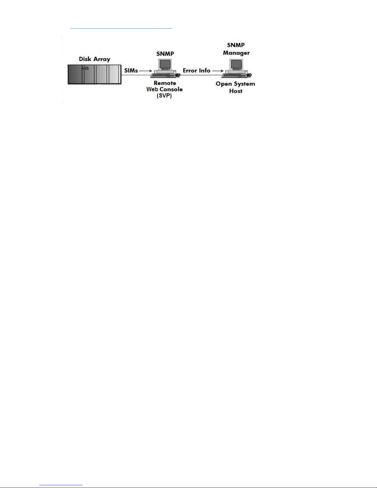
http://www.hp.com/support/manuals.
Figure 1 SNMP configuration
XP RAID Manager command devices
HP StorageWorks XP RAID Manager manages HP StorageWorks XP Business Copy Software or HP
StorageWorks XP Continuous Access Software operations from a host server. To use XP RAID Manager
with XP Business Copy Software or XP Continuous Access Software, you use XP Remote Web Console
or XP Command View, to designate at least one LDEV as a command device. Refer to the applicable
user's guide for information about how to designate a command device.
Installation roadmap
Perform these actions to install and configure the disk array:
1. Installing and configuring the disk array
• Setting the host mode for the disk array ports
• Setting the System Option Modes
• Configuring the Fibre Channel ports
2. Installing and configuring the host
• Loading the operating system and software
• Installing and configuring the FCAs
• Setting up clustering and fabric zoning
• Fabric zoning and LUN security for multiple operating systems
3. Connecting the disk array
• Defining the paths
• Verifying host recognition of disk array devices
4. Configuring disk devices
• Writing the partition labels
• Creating the file systems
• Creating mount directories
• Mounting the file systems
• Verifying the file systems
• Setting and verifying automatic mounting at bootup
XP Disk Array Configuration Guide for Tru64 UNIX 9
Page 10

Installing and configuring the disk array
The HP service representative performs these tasks:
• Assembling hardware and installing software
• Loading the microcode updates
• Installing and formatting devices
• Configuring array groups and creating LDEVs
After these tasks are finished, use XP Remote Web Console, XP Command View, or XP Array Manager
to complete the remaining tasks listed below. For procedures, refer to the applicable user guide
available at:
http://www.hp.com/support/manuals.
If you do not have these programs, your HP service representative can perform these tasks for you.
IMPORTANT:
For optimal performance when configuring any XP disk array with a Tru64 host, HP does not
recommend:
• Sharing of CHA (channel adapter) microprocessors
• Multiple host groups sharing the same CHA port
NOTE:
As illustrated in the following table, there is no microprocessor sharing with 8–port module pairs.
With 16– and 32–port module pairs, alternating ports are shared.
Table 1 Microprocessor port sharing
Ports SharedNr. of Ports
Adapter
DescriptionModelChannel
per Microprocessor
N/A18-port 2GB CHIP Pair8HSRAE020A
216-port 2GB CHIP Pair16HSRAE006A
232-port 2GB CHIP Pair32HSRAE007A
216-port 4GB CHIP Pair16FS2RAE022A
232-port 4GB CHIP Pair32FS2RAE023A
CL1 - 1 & 5; 3 & 7
CL2 - 2 & 6; 4 & 8
CL1 - 1 & 5; 3 & 7
CL2 - 2 & 6; 4 & 8
N/A18-port 4GB CHIP Pair8FS2RAE021A
CL1 - 1 & 5; 3 & 7
CL2 - 2 & 6; 4 & 8
CL1 - 1 & 5; 3 & 7
CL2 - 2 & 6; 4 & 8
Installing and configuring Tru64 for the XP disk array10
Page 11
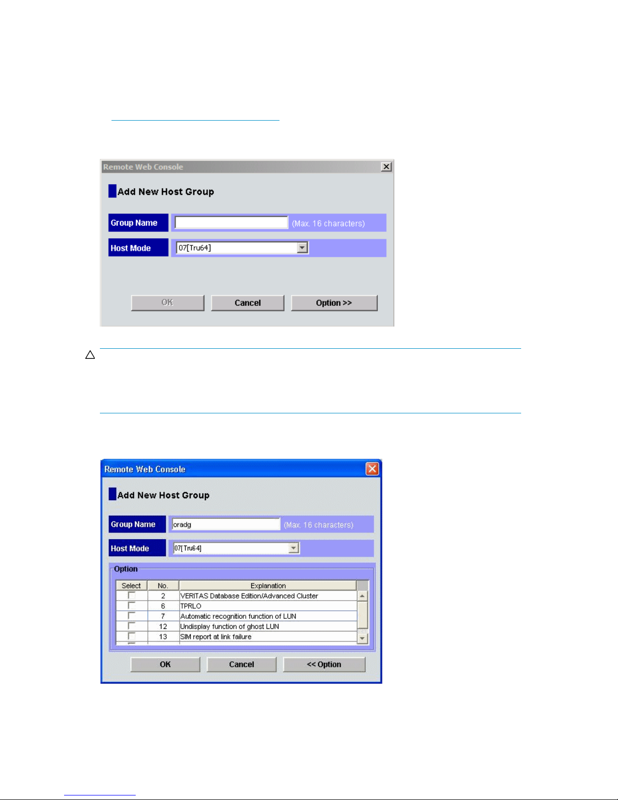
Setting the host mode and host group mode for the disk array ports
After the disk array is installed, you must set the host mode for each host group that is configured on
a disk array port to match the host OS. Set the host mode using LUN Manager in XP Remote Web
Console (shown), or XP Command View. For procedures, refer to the applicable user guide available
at http://www.hp.com/support/manuals. If these are not available, the HP service representative
can set the host mode using the SVP.
The required host mode setting for Tru64 is 07.
CAUTION:
The correct host mode must be set for all new installations (newly connected ports) to Tru64 hosts. Do
not select a mode other than 07 for Tru64. Changing a host mode after the host has been connected
is disruptive and requires the server to be rebooted.
When a new host group is added, additional host group modes (options) may be configured. The
storage administrator must verify if an additional host group mode is required for the host group.
XP Disk Array Configuration Guide for Tru64 UNIX 11
Page 12
The following host group mode (option) is available for Tru64:
Table 2 Host group mode (option)
Host
Group
Mode
CommentsDefaultFunction
14
CAUTION:
Changing host group modes for ports where servers are already installed and configured breaks all
LUN paths and will require the paths to be redefined. See “Defining the paths” on page 16. If host
group mode 14 is applied to an existing LUN, Tru64 will need to be installed again. If XP Continuous
Access is going to be used, the host group mode must be set before the installing Tru64.
Enable use of XP Continuous Access Software
on Tru64 TruClusters.
Setting the System Option Modes
The HP service representative sets the System Option Mode(s) based on the operating system and
software configuration of the host. Notify your HP representative if you install storage agnostic software
(such as backup or cluster software) that may require specific settings.
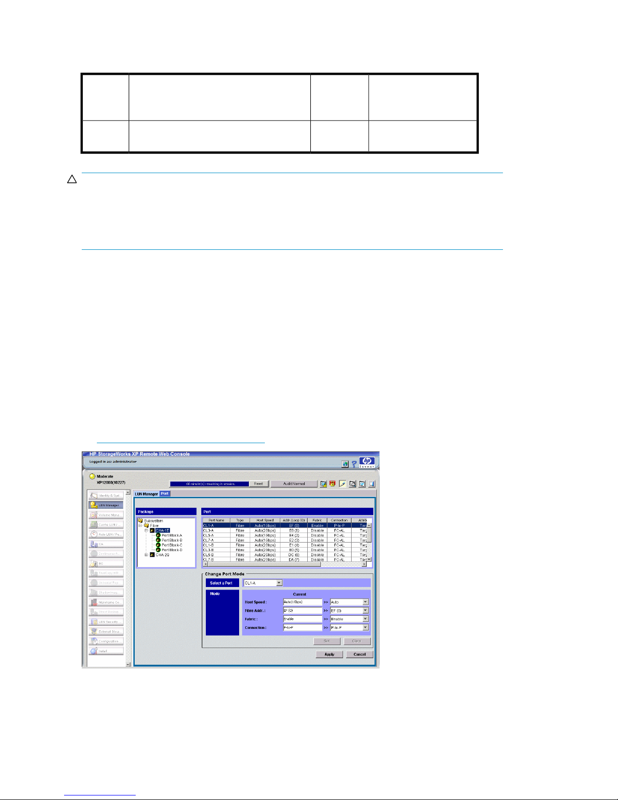
Configuring the Fibre Channel ports
Configure the disk array Fibre Channel ports by using Remote Web Console (shown), or XP Command
View. Select the settings for each port based on your storage area network topology. Use switch
zoning if you connect different types of hosts to the array through the same switch. For detailed
procedures, refer to HP StorageWorks XP LUN Manager User's Guide available at:
Inactive
Previously MODE272
http://www.hp.com/support/manuals.
Installing and configuring Tru64 for the XP disk array12
Page 13

Fibre address
In fabric environments, the port addresses are assigned automatically.
Fabric and connection parameter settings
Set each array port to FABRIC ENABLE with connections of POINT-TO -POINT (P-to-P). For detailed
topology information, refer to the HP StorageWorks SAN Design Reference Guide available at:
http://www.hp.com/go/sandesign.
Installing and configuring the host
This section explains how to install and configure Fibre Channel adapters (FCAs) that connect the
host to the disk array.
Loading the operating system and software
Follow the manufacturer's instructions to load the operating system and software onto the host. Load
all OS patches and configuration utilities supported by HP and the FCA manufacturer.
CAUTION:
If you plan to use XP Continuous Access Software, you must configure XP Continuous Access first
before installing Tru64. If you configure XP Continuous Access after installing Tru64, the unit identifier
returned to Tru64 is changed resulting in loss of recognition of current disks.
Installing and configuring the FCAs
Install and configure the Fibre Channel adapters using the FCA manufacturer's instructions.
Set FCA fabric mode
Set the FCAs to run in fabric mode as follows.
1. Display the FCA configuration.
P00>>>wwidmgr -show adapter
2. Set the FCA topology to fabric. The 9999 qualifier sets all adapters with one command.
P00>>>wwidmgr -set adapter -item 9999 -topo fabric
Using wwidmgr
When booting from an XP disk array, use the following procedure to create the bootable device within
the console:
XP Disk Array Configuration Guide for Tru64 UNIX 13
Page 14

1. Show all wwids.
P00>wwidmgr -show wwid
[0] UDID:176 WWID:01000010:6006-0e80-0350-6200-0009-0010-5062-00b0 (ev:none)
[1] UDID:177 WWID:01000010:6006-0e80-0350-6200-0009-0010-5062-00b1 (ev:none)
[2] UDID:178 WWID:01000010:6006-0e80-0350-6200-0009-0010-5062-00b2 (ev:none)
[3] UDID:179 WWID:01000010:6006-0e80-0350-6200-0009-0010-5062-00b3 (ev:none)
[4] UDID:180 WWID:01000010:6006-0e80-0350-6200-0009-0010-5062-00b4 (ev:none)
[5] UDID:181 WWID:01000010:6006-0e80-0350-6200-0009-0010-5062-00b5 (ev:none)
[6] UDID:182 WWID:01000010:6006-0e80-0350-6200-0009-0010-5062-00b6 (ev:none)
[7] UDID:183 WWID:01000010:6006-0e80-0350-6200-0009-0010-5062-00b7 (ev:none)
[8] UDID:184 WWID:01000010:6006-0e80-0350-6200-0009-0010-5062-00b8 (ev:none)
[9] UDID:185 WWID:01000010:6006-0e80-0350-6200-0009-0010-5062-00b9 (ev:none)
[10] UDID:186 WWID:01000010:6006-0e80-0350-6200-0009-0010-5062-00ba (ev:none)
2. Set the disk you installed the boot file system on:
P00>wwidmgr -quickset -item 2 -unit 1
3. Check the disk assignment and reachability.
P00>wwidmgr -show reach
Disk assignment and reachability after next initialization:
6006-0e80-0350-6200-0009-0010-5062-00b2
via adapter: via fc nport: connected:
dga1.1001.0.4.1 pga0.0.0.4.1 5006-0e80-0350-6211 Yes
dgb1.1001.0.3.0 pgb0.0.0.3.0 5006-0e80-0350-6211 Yes
4. Initialize the system.
P00>init
5. Show devices.
P00>show dev d
dga1.1001.0.4.1 $1$DGA1 HP OPEN-V 2114
dgb1.1001.0.3.0 $1$DGA1 HP OPEN-V 2114
dka0.0.0.2004.0 DKA0 COMPAQ BF01863644 3B05
dka500.5.0.2004.0 DKA500 COMPAQ BF01863644 3B05
dqa0.0.0.15.0 DQA0 Compaq CRD-8402B 1.03
dva0.0.0.1000.0 DVA0
The list of adapters is displayed, showing fabric topology.
6. Set the Boot default device.
P00>set bootdef_dev dga1.1001.0.4.1,dgb1.1001.0.3.0
7. Boot the system.
P00>boot
Installing and configuring Tru64 for the XP disk array14
Page 15

Configuring system files
Configure the Tru64 system to recognize the FCA as explained in the Tru64 Installation Guide or
New Hardware Delivery (NHD) kit. This consists of booting genvmunix and executing doconfig (as
explained in the Installation Guide). This can also be done by editing the system kernel configuration
file as explained below.
1. Use the doconfig -c config_file command to reconfigure the kernel, where
config_file is usually the system name.
2. When you add a new FCA after an FCA of the same type has already been installed, a simple
reboot causes the host to recognize the new FCA. No rebuilding or reconfiguration is required.
Clustering and fabric zoning
If you plan to use clustering, install and configure the clustering software on the servers.
Clustering is the organization of multiple servers into groups. Within a cluster, each server is a node.
Multiple clusters compose a multi-cluster environment. The following example shows a multi-cluster
environment with three clusters, each containing two nodes. The nodes share access to the disk array.
In this example, the array is configured so that Host Group 00 is presented only to Cluster 1, Host
Group 01 only to Cluster 2, and Host Group 02 only to Cluster 3. Always configure an array so that
a host group is presented to only 1 cluster.
Figure 2 Multi-cluster environment
Within the Storage Area Network (SAN), the clusters may be homogeneous (all the same operating
system) or they may be heterogeneous (mixed operating systems). How you configure LUN security
and fabric zoning depends on the operating system mix and the SAN configuration.
Fabric zoning and LUN security for multiple operating systems
You can connect multiple clusters of various operating systems to the same switch and fabric using
appropriate zoning and LUN security as follows:
• Storage port zones may overlap if more than one operating system needs to share an array port.
XP Disk Array Configuration Guide for Tru64 UNIX 15
Page 16

• Heterogeneous operating systems may share an XP array port if you use Secure Manager and set
the appropriate host group and mode. All others must connect to a dedicated XP array port.
• Use Secure Manager for LUN isolation when multiple hosts connect through a shared array port.
Secure Manager provides LUN security by allowing you to restrict which LUNs each host can access.
Table 3 Fabric zoning and LUN security settings
LUN SecurityFabric ZoningOS MixEnvironment
Standalone SAN
(non-clustered)
Clustered SAN
Multi-Cluster SAN
homogeneous (a single OS type
present in the SAN)
heterogeneous (more than one OS
type present in the SAN)
Connecting the disk array
The HP service representative connects the disk array to the host by:
1. Verifying operational status of the disk array channel adapters, LDEVs, and paths.
2. Connecting the Fibre Channel cables between the disk array and the fabric switch or host.
3. Verifying the ready status of the disk array and peripherals.
Defining the paths
Use XP Remote Web Console (shown), or XP Command View to define paths (LUNs) between hosts
and volumes in the disk array.
This process is also called “LUN mapping.” In XP Remote Web Console and XP Command View,
LUN mapping includes:
• Configuring ports
• Enabling LUN security on the ports
• Creating host groups
• Assigning Fibre Channel adapter WWNs to host groups
• Mapping volumes (LDEVs) to host groups (by assigning LUNs)
Not required
Required
Must be used when multiple hosts or cluster nodes
connect through a shared
port
Installing and configuring Tru64 for the XP disk array16
Page 17

Verifying host recognition of disk array devices
Use the hwmgr show scsi command at the UNIX prompt to see the list of new disk array devices.
The device files are created automatically in Tru64 UNIX during system startup. Device files are created
for each logical unit.
1. Verify the character-type device files have been automatically created:
Example — Tru64 5.1B
# file /dev/rdisk/dsk*
2. Verify the block-type device files have been automatically created:
Example — Tru64 5.1B
# file /dev/disk/dsk*
Configuring disk devices
Configure disks in the disk array using the same procedure for configuring any new disk on the host.
This includes the following procedures:
1. Writing the partition labels
2. Creating the file systems
3. Creating mount directories
4. Mounting the file systems
5. Verifying the file systems
6. Setting and verifying automatic mounting at bootup
7. Checking path failover
Creating scripts to configure all devices at once may save you considerable time.
XP Disk Array Configuration Guide for Tru64 UNIX 17
Page 18

Refer to Tru64 UNIX System Administration for detailed procedures.
Writing the partition labels
Use the disklabel command to label the partition for each logical unit. Partition c specifies the
entire area in the logical unit. Check that no errors are found in the partition settings after the labeling.
You can edit the disk partition size using the disklabel command with option –e. When the
disklabel –e command is executed, the vi editor for the environment in which you are working
starts up. After completing the editing, save the file and execute the disklabel command again;
the partition setting is renewed.
Procedure to write the partition label:
1. Enter disklabel –rw.
Specify the disk name.
Example — Tru64 5.1B
# disklabel –rw dsk10 OPEN-3
2. Enter disklabel –r to verify labeling and partition settings.
Specify the disk name.
Example — Tru64 5.1B
# disklabel –r dsk10
Creating the file systems
Create a file system for each new OPEN-x device. Optionally, you can create and use an advanced
file system (AdvFS) to overcome the size and speed limitations of the file system. If you are not sure
which file system is right for your setup, contact HP customer support.
Creating a file system for each device:
# newfs device_file_name
Creating an advanced file system:
You can create a new advanced file system domain, or you can add a new fileset to an existing
domain.
If you allocate multiple disk partitions to a domain, the advanced file system utilities must be installed.
Example
# addvol /dev/disk/dsk8c domain1
1. Create a new domain.
# mkfdmn device_file_name domain_name
Installing and configuring Tru64 for the XP disk array18
Page 19

2. Create a new fileset in the new or existing advanced file system domain.
# mkfset domain_name fileset_name
Creating mount directories
Create a mount directory for each device. Assign each mount directory a unique name that identifies
the device being mounted.
1. Create a mount directory.
# mkdir /mount_directory_name
Example
To create a mount directory for LUN 2 (partition c) on the disk array, enter:
# mkdir /HP5700_LU2c
2. Verify the new mount directory.
Example
# ls /
Mounting the file systems
After the file systems and mount directories have been created, mount the file system for each new
device.
Mounting a Tru64 file system:
1. Mount device:
# mount device_file_name mount_directory
Example — Tru64 5.1B
To mount device dsk10c with mount directory name HP5700_LU2c, enter:
# mount /dev/disk/dsk10c HP5700_LU2c
2. Assign the appropriate ownership and permissions:
# chown owner:group *device_file_name*
Example — Tru64 5.1B
To assign ownership to dsk10c with owner Oracle, group dba enter:
# chown oracle:dba *dsk10c*
XP Disk Array Configuration Guide for Tru64 UNIX 19
Page 20

Mounting an advanced file system:
1. Mount the file system:
# mount –t advfs domain_name#fileset_name mount_directory
Example
To mount the file system with mount directory:
mount –t advfs domain1#fileset1 /HP5700_LU2c
2. Assign the appropriate ownership and permissions:
# chown owner:group*device_file_name*
Example
To assign ownership to dsk10c with owner Oracle, group dba, enter:
chown oracle:dba *dsk10c*
Verifying the file systems
Verify that the new file systems were created correctly and are functioning properly.
1. Display all mounted file systems.
# df
The default display for drive capacity is 512-byte blocks. To view the capacity in kilobytes rather
than in 512-byte blocks, enter df –k.
2. Go to a new device directory:
# cd /mount_directory
Example
cd /HP5700_LU2c
3. Copy a file from the root directory to the new device:
# cp /filename file_name.back1
Example
To copy file vmunix from the root directory to the HP5700_LU2c device, enter:
cp /vmunix vmunix.back1
Installing and configuring Tru64 for the XP disk array20
Page 21

4. Copy a file to the new device again:
# cp /filename file_name.back2
Example
To copy the same file again, enter:
cp /vmunix vmunix.back2
5. List the files in the current directory:
Example
# ls –l
The vmunix.back1 and vmunix.back2 files should be shown.
6. Delete the files you copied:
# rm file_name
Example
To remove the file.
vmunix.back1
Setting and verifying automatic mounting at bootup
The /etc/fstab file contains boot time mounting parameters for disk devices.
XP Disk Array Configuration Guide for Tru64 UNIX 21
Page 22

1. After first making a backup copy of the file, edit the /etc/fstab file. Add a line for each new
device to be mounted.
Example
#vi /etc/fstab
/dev/disk/dsk4a / ufs rw 1 1
/proc /proc procfs rw 0 0
/dev/disk/dsk12a /usr ufs rw 1 2
/dev/disk/dsk12b swap1 ufs rw 0 2
/dev/disk/dsk15c /HP5700_LU2c ufs rw 1 3
Table 4 Automatic mounting example explanation
Notes: For UFS systems, you must File System Check (fsck) disks that contain mount points before
mounting other disks on those mount points.
2. Shut down and reboot the system.
3. Use the df or df –k command to verify file system auto mounting.
Checking path failover
The disk array supports Tru64 path failover (Tru64 v5.1B–2 and later only). You can connect multiple
FCAs to the disk array with shared LUNs. Confirm the existence of multiple paths for devices as follows:
1. Type hwmgr -view device to obtain the HWID for the device.
File systemMnt PointDevice
Options
(r/w)
yes=1)
fsck orderBackup (no=0,
11rwufs//dev/disk/dsk4a
00rwprocfs/proc/proc
21rwufs/usr/dev/disk/dsk12a
20rwufsswap1/dev/disk/dsk12b
31rwufs/HP700_LU2c/dev/disk/dsk15a
2. Type hwmgr -show scsi -full -id HWID to confirm the status of paths to the device.
If more than one path is currently connected, the status of each path shows as Valid. If you
change the cabling configuration, the old paths will show as Stale. Use the hwmgr -refresh
scsi command to remove the stale paths.
CAUTION:
Tru64 5.1B and later fully support dynamic load balancing and failover when multiple FCAs
are connected to the same LUN. This feature is ONLY available with version 5.1B and later.
Installing and configuring Tru64 for the XP disk array22
Page 23

2 Troubleshooting
This section includes resolutions for various error conditions you may encounter.
If you are unable to resolve an error condition, ask your HP support representative for assistance.
Error conditions
Depending on your system configuration, you may be able to view error messages (R-SIMS) as follows:
• In XP Remote Web Console (Status tab)
• In XP Command View (Event History or Event Notification panels)
Table 5 Error conditions
The logical devices are not recognized
by the host.
Recommended actionError condition
Verify the following:
• The READY indicator lights on the disk array are ON.
• Fiber cables are correctly installed and firmly connected.
• The target IDs are properly configured. The LUNs for each TID
must start at 0 and continue sequentially without skipping any
numbers.
• The TIDs/WWNs on each bus are unique. Do not install two
devices with the same ID on the same bus. Recheck the buses for
new devices.
• LUSE devices are not intermixed with normal LUNs on the same
port.
• The maximum number of LUSE devices per port has not been ex-
ceeded.
• The disk array host mode is set correctly.
• The data in the emx_data.c file correctly maps each WWN to
a TID between 0 and 7.
The host does not reboot properly after
hard shutdown.
Logical volumes cannot be created.
If you power off the host without executing the shutdown process,
wait three minutes to allow the disk array's internal timeout process
to purge queued commands. If the host restarts while the disk array
is processing queued commands, the host may not reboot successfully.
Verify that the disk array logical devices are correctly formatted.Physical volumes cannot be created.
Verify that the volume capacity for OPEN-x volumes is not greater
than the maximum capacity allowed. See “Disk array supported
emulations” on page 29 for capacities.
Verify that the capacity of the volume group is not less than the total
capacity of the partitioned logical volume.
Verify that logical volume name is a character-type volume.A file system cannot be created.
XP Disk Array Configuration Guide for Tru64 UNIX 23
Page 24

Recommended actionError condition
A file system is not mounted after rebooting.
The disk array performs a self reboot
because the disk array was busy or it
logged a panic message.
The disk array responds “Not Ready”
or the disk array has displayed “Not
Ready” and timed out.
The host detects a parity error.
The host hangs or devices are declared
and the host hangs.
Verify that the host was restarted correctly.
Verify that the file system attributes are correct.
Reboot the host.
Contact HP.
Check the FCA and make sure it was installed properly.
Reboot the host.
Make sure there are no duplicate disk array TIDs and that disk array
TIDs do not conflict with any host TIDs.
Troubleshooting24
Page 25

3 Support and other resources
Related documentation
The following documents provide related information:
• HP StorageWorks XP10000 Disk Array: Owner's Guide
• HP StorageWorks XP12000 Disk Array: Owner's Guide
• HP StorageWorks XP20000 Disk Array: Owner's Guide
• HP StorageWorks XP24000 Disk Array: Owner's Guide
• HP StorageWorks XP LUN Manager User's Guide
• HP StorageWorks SAN Design Reference Guide
• HP StorageWorks XP Secure Manager User's Guide
• Tru64 UNIX System Administration
You can find these documents on the HP Manuals website:
http://www.hp.com/support/manuals
In the Storage section, click Disk Storage Systems and then select a product.
Conventions for storage capacity values
HP XP storage systems use the following values to calculate physical storage capacity values (hard
disk drives):
• 1 KB (kilobyte) = 1,000 bytes
•
1 MB (megabyte) = 1,0002 bytes
•
1 GB (gigabyte) = 1,0003 bytes
•
1 TB (terabyte) = 1,0004 bytes
•
1 PB (petabyte) = 1,0005 bytes
HP XP storage systems use the following values to calculate logical storage capacity values (logical
devices):
• 1 KB (kilobyte) = 1,024 bytes
•
1 MB (megabyte) = 1,0242 bytes
•
1 GB (gigabyte) = 1,0243 bytes
•
1 TB (terabyte) = 1,0244 bytes
•
1 PB (petabyte) = 1,0245 bytes
• 1 block = 512 bytes
XP Disk Array Configuration Guide for Tru64 UNIX 25
Page 26

HP technical support
For worldwide technical support information, see the HP support website:
http://www.hp.com/support
Before contacting HP, collect the following information:
• Product model names and numbers
• Technical support registration number (if applicable)
• Product serial numbers
• Error messages
• Operating system type and revision level
• Detailed questions
Subscription service
HP recommends that you register your product at the Subscriber's Choice for Business website:
http://www.hp.com/go/e-updates
After registering, you will receive e-mail notification of product enhancements, new driver versions,
firmware updates, and other product resources.
HP websites
For additional information, see the following HP websites:
•http://www.hp.com
•http://www.hp.com/go/storage
•http://www.hp.com/support/manuals
•http://www.hp.com/storage/spock
Documentation feedback
HP welcomes your feedback.
To make comments and suggestions about product documentation, please send a message to
storagedocsFeedback@hp.com. All submissions become the property of HP.
Support and other resources26
Page 27

A Path worksheet
Worksheet
Table 6 Path worksheet
LDEV (CU:LDEV) (CU =
control unit)
0:00
0:01
0:02
0:03
0:04
0:05
0:06
Device Type
SCSI Bus
Number
Alternate PathsPath 1
TID:
LUN:
TID:
LUN:
TID:
LUN:
TID:
LUN:
TID:
LUN:
TID:
LUN:
TID:
LUN:
TID:
LUN:
TID:
LUN:
TID:
LUN:
TID:
LUN:
TID:
LUN:
TID:
LUN:
TID:
LUN:
TID:
LUN:
TID:
LUN:
TID:
LUN:
TID:
LUN:
TID:
LUN:
TID:
LUN:
TID:
LUN:
0:07
0:08
0:09
0:10
TID:
LUN:
TID:
LUN:
TID:
LUN:
TID:
LUN:
TID:
LUN:
TID:
LUN:
TID:
LUN:
TID:
LUN:
TID:
LUN:
TID:
LUN:
TID:
LUN:
TID:
LUN:
XP Disk Array Configuration Guide for Tru64 UNIX 27
Page 28

Path worksheet28
Page 29

B Disk array supported emulations
This appendix provides information about supported emulations and device type specifications. Some
parameters may not be relevant to your array. Consult your HP representative for information about
supported configurations for your system.
Supported emulations
HP recommends using OPEN-V as the emulation for better performance and features that may not be
supported with the legacy emulations (OPEN-[389LE]).
Table 7 Supported emulations
LUSE & CVSCVSLUSEFixed SizeEmulationXP model
YesYesYesYesOPEN-3
XP10000
XP12000
XP20000
XP24000
OPEN-K
OPEN-M
Emulation specifications
Table 8 Emulation specifications
Emulation
(Note 1)
Category
(Note 2)
Product name
(Note 3)
YesYesOPEN-L
Blocks
(512 bytes)
Sector
size
(bytes)
cylinders
YesYesYesYesOPEN-8
YesYesYesYesOPEN-9
YesYesYesYesOPEN-E
YesYesOPEN-V
Heads# of
Sectors
per
track
Capacity
MB*
(Note 4)
2347961533385124806720OPEN-3SCSI diskOPEN-3
70079615996651214351040OPEN-8SCSI diskOPEN-8
704296151001651214423040OPEN-9SCSI diskOPEN-9
1389396151975951228452960OPEN-ESCSI diskOPEN-E
3476196154943951271192160OPEN-LSCSI diskOPEN-L
XP Disk Array Configuration Guide for Tru64 UNIX 29
Page 30

Emulation
(Note 1)
LUSE
CVS
Category
(Note 2)
Product name
(Note 3)
Blocks
(512 bytes)
Sector
size
(bytes)
cylinders
Heads# of
Sectors
per
track
Capacity
MB*
(Note 4)
2347*n96153338*n5124806720*nOPEN-3*nSCSI diskOPEN-3*n
7007*n96159966*n51214351040*nOPEN-8*nSCSI diskOPEN-8*n
7042*n961510016*n51214423040*nOPEN-9*nSCSI diskOPEN-9*n
13893*n961519759*n51228452960*nOPEN-E*nSCSI diskOPEN-E*n
34761*n961549439*n51271192160*nOPEN-L*nSCSI diskOPEN-L*n
Note 79615Note 6512Note 5OPEN-3-CVSSCSI diskOPEN-3 CVS
Note 79615Note 6512Note 5OPEN-8-CVSSCSI diskOPEN-8 CVS
Note 79615Note 6512Note 5OPEN-9-CVSSCSI diskOPEN-9 CVS
Note 79615Note 6512Note 5OPEN-E-CVSSCSI diskOPEN-E CVS
Note 712815Note 6512Note 5OPEN-VSCSI diskOPEN-V
CVS LUSE
OPEN-3*n CVS
General notes:
*Capacity = (512 x number of blocks) ÷ 1024
The value n is the number of volumes combined together. For example, with 8 combined volumes:
OPEN-V*8.
Note 1:
The availability of an emulation depends on the disk array.
Note 2:
The devices are defined to the host as SCSI disk devices, even though the interface is Fibre Channel.
Note 79615Note 6512Note 5OPEN-3*n-CVSSCSI disk
Note 79615Note 6512Note 5OPEN-8*n-CVSSCSI diskOPEN-8*n CVS
Note 79615Note 6512Note 5OPEN-9*n-CVSSCSI diskOPEN-9*n CVS
Note 79615Note 6512Note 5OPEN-E*n-CVSSCSI diskOPEN-E*n CVS
Note 712815Note 6512Note 5OPEN-V*nSCSI diskOPEN-V*n
2
Note 3:
The command device (used for XP Raid Manager) is distinguished by -CM on the product name (for
example, OPEN-3-CM, OPEN-3-CVS-CM).
Disk array supported emulations30
Page 31

Note 4:
Note 5:
Note 6:
The device capacity can sometimes be changed by the BIOS or host adapter board. This may make
actual capacity different from that listed in the table.
The number of blocks for a CVS volume is calculated as follows:
# of blocks = (# of cylinders) × (# of heads) × (# of sectors per track)
Example
For an OPEN-3 CVS volume with capacity = 37 MB:
# of blocks = (53 cylinders–see Note 5) × (15 heads) ×
(96 sectors per track) = 76320
Example
For an OPEN-V CVS volume with capacity = 49 MB:
# of blocks = (53 cylinders–see Note 5) × (15 heads) ×
(128 sectors per track) = 101760
The number of cylinders for a CVS volume is calculated as follows ( ... means that the value should
be rounded up to the next integer):
OPEN-3/8/9/E: The number of cylinders for a CVS volume = # of cylinders = (capacity (MB)
specified by user) × 1024/720
Example
For an OPEN-3 CVS volume with capacity = 37 MB:
# of cylinders = 37 × 1024/720 = 52.62
(rounded up to next integer) = 53 cylinders
OPEN-V: The number of cylinders for a CVS volume = # of cylinders = (capacity (MB) specified by
user) × 16/15
Example
For an OPEN-V CVS volume with capacity = 49 MB:
# of cylinders = 49 × 16/15 = 52.26
(rounded up to next integer) = 53 cylinders
OPEN-3/8/9/E: The number of cylinders for a CVS LUSE volume = # of cylinders = (capacity (MB)
specified by user) × 1024/720 × n
Example
For a CVS LUSE volume with capacity = 37 MB and n = 4:
# of cylinders = 37 × 1024/720 × 4 = 52.62 × 4 = 53 × 4 = 212
OPEN-V: The number of cylinders for a CVS LUSE volume = # of cylinders = (capacity (MB) specified
by user) × 16/15 × n
Example
For an OPEN-V CVS LUSE volume with capacity = 49 MB and n = 4:
# of cylinders = 49 × 16/15 × 4 = 52.26 × 4 = 53 × 4 = 212
XP Disk Array Configuration Guide for Tru64 UNIX 31
Page 32

Note 7:
The capacity of an OPEN-3/8/9/E CVS volume is specified in MB, not number of cylinders. The
capacity of an OPEN-V CVS volume can be specified in MB or number of cylinders. You set the
volume size using XP Remote Web Console or XP Command View.
Disk array supported emulations32
Page 33

Glossary
AL-PA Arbitrated loop physical address.
array group A group of 4 or 8 physical hard disk drives (HDDs) installed in an XP disk array
CHA Channel Adapter: Front end PCBs in XP arrays responsible for communication
command device A volume on the disk array that accepts XP Continuous Access Software or XP
CU Control Unit. Contains LDEVs and is approximately equivalent to SCSI Target ID.
CVS Custom volume size. CVS devices (OPEN-x CVS) are custom volumes configured
and assigned a common RAID level. RAID1 array groups consist of 4 (2D+2D)
or 8 HDDs (4D+4D). RAID5 array groups include a parity disk but also consist
of 4 (3D+1P) or 8 HDDs (7D+1P). All RAID6 array groups are made up of 8
HDDs (6D+2P).
to other devices, typically Hosts, though they are also involved in data exchange
with external storage.
Business Copy Software control operations which are then executed by the disk
array.
using array management software to be smaller than normal fixed-size OPEN
system volumes. Synonymous with volume size customization (VSC). OPEN-V is
a CVS-based volume.
emulation modes The logical devices (LDEVs) associated with each RAID group are assigned an
emulation mode that makes them operate like OPEN system disk drives. The
emulation mode determines the size of an LDEV:
OPEN-3: 2.46 GB
OPEN-8: 7.38 GB
OPEN-9: 7.42 GB
OPEN-E: 13.56 GB
OPEN-L: 36 GB
OPEN-V: User-defined custom size
failover Using an alternate unit or path instead of a failed unit or path in order to continue
functioning.
FC Fibre Channel.
FCA Fibre Channel Adapter.
FC-AL Fibre Channel arbitrated loop.
FCP Fibre Channel Protocol.
HBA Host bus adapter.
XP Disk Array Configuration Guide for Tru64 UNIX 33
Page 34

host mode Each port can be configured for a particular host type. These modes are
represented as two-digit hexadecimal numbers. For example, host mode 08
represents an HP-UX host.
LDEV Logical device. An LDEV is created when a RAID group is carved into pieces
according to the selected host emulation mode (that is, OPEN-3, OPEN-8,
OPEN-E). The number of resulting LDEVs depends on the selected emulation
mode. The term LDEV is often used synonymously with the term volume.
LUN Logical unit number. A LUN results from mapping a SCSI logical unit number,
port ID, and LDEV ID to a RAID group. The size of the LUN is determined by the
emulation mode of the LDEV and the number of LDEVs associated with the LUN.
For example, a LUN associated with two OPEN-3 LDEVs has a size of 4,693
MB.
LUSE A LUN is normally associated with only a single LDEV. The LUSE feature allows
a LUN to be associated with 1 to 36 LDEVs. Essentially, LUSE makes it possible
for applications to access a single large pool of storage. The LUSE feature is
available when the HP StorageWorks Array Manager product is installed.
OFC Open Fibre Control.
OPEN-
x
A general term describing any one of the supported OPEN emulation modes (for
example, OPEN-E. There are two types of OPEN-x devices: legacy OPEN-x
devices with a fixed size (such as, OPEN-3, OPEN-8, OPEN-9, OPEN-E), and
OPEN-V, which has a variable size and is a CVS-based volume.
PA Physical address.
path “Path” and “LUN” are synonymous. Paths are created by associating a port and
a LUN ID with an LDEV.
port A physical connection that allows data to pass between a host and the disk
array. The number of ports on an XP disk array depends on the number of
supported I/O slots and the number of ports available per I/O adapter. The XP
family of disk arrays supports Fibre Channel (FC) ports as well as other port
types. Ports are named by port group and port letter, such as CL1-A. CL1 is the
group, and A is the port letter.
RAID Redundant array of independent disks.
R-SIM Remote service information message.
SCSI Small computer system interface.
SIM Service information message.
SNMP Simple Network Management Protocol.
SVP Service processor, which is the PC built into the disk array. The SVP provides a
direct interface into the disk array. SVP use is reserved for HP support
representatives only.
TID Target ID.
Volume On the XP array, a volume is a uniquely identified virtual storage device
composed of a control unit (CU) component and a logical device (LDEV)
component separated by a colon. For example 00:00 and 01:00 are two
Glossary34
Page 35

uniquely identified volumes; one is identified as CU = 00 and LDEV = 00, and
the other as CU = 01 and LDEV = 00; they are two unique separate virtual
storage devices within the XP array.
VSC Volume size customization. Synonymous with CVS.
WWN World Wide Name. A unique identifier assigned to a Fibre Channel device.
XP Command
View
XP Remote Web
Console
HP StorageWorks XP Command View, a software product for managing XP
arrays. Command View runs on a Windows-based management workstation.
HP StorageWorks XP Remote Web Console. A browser-based program installed
on the SVP that allows you to configure and manage the disk array.
XP Disk Array Configuration Guide for Tru64 UNIX 35
Page 36

Glossary36
Page 37

Index
A
advanced file system (AdvFS), 18
arbitrated-loop physical address, 13
automatic mounting, 21
C
clustering, 15
command device(s)
designate at least one LDEV as a, 9
XP RAID Manager, 9
configuration
device, 17
emulation types, 8
FCAs, 13
Fibre Channel ports, 12
host, 13
host mode, setting, 11
port, 12
system files, 15
System Mode, 12
console commands
df, 20
mkfset, 19
mount, 19
conventions
storage capacity values, 25
D
device(s)
automatic mounting, 21
configuration, 17
emulation types, 8
logical, not recognized by host, 23
mount file system, 19
recognition, 17
type specifications, 30
verifying, 17
directories, mount, 19
disk array(s)
connecting, 16
features, 7
installation, 10
installation overview, 9
Not Ready error message, 24
operating system versions, 7
self reboots, 24
server support, 7
storage capacity, 7
system requirements, 7
disk partition(s)
allocate multiple, 18
change size, 18
document
related documentation, 25
documentation
HP website, 25
providing feedback, 26
E
emulation(s)
device emulation types, 8
supported, 29
error conditions, 23
F
fabric environment
parameter settings, 13
port addresses, 13
zoning, 15
failover, 8
checking, 22
FCA(s)
configuring, 13
supported, 13
FCA(s) card, verify installation, 13
fiber parameter settings, 13
XP Disk Array Configuration Guide for Tru64 UNIX 37
Page 38

Fibre Channel
connection speed, 7
interface, 7
parameter settings, 13
ports, configuring, 12
supported elements, 7
topology example, 13
Fibre Channel adapters, see "FCAs", 7
file system(s)
advanced (AdvFS), 18, 20
cannot be created, 23
creating, 18
mounting, 19
not mounted after rebooting, 24
verify installation, 20
G
glossary, 33
H
help
obtaining, 26
host
configuration, 13
doesn't reboot properly, 23
hangs up, 24
host mode, setting, 11
HP
technical support, 26
I
installation
connecting disk array, 16
disk array, 10
overview, 9
verify FCA card, 13
verify file system, 20
interface, Fibre Channel, 7
L
LDEV(s)
designate at least one as a command device,
9
logical volumes, cannot be created, 23
LUN(s)
creating, 16
mapping, 16
LUN(s), security, 15
M
mount directories, creating, 19
multi-cluster environment, 15
O
operating system(s)
loading, 13
LUN security for, 15
multiple, fabric zoning for, 15
supported versions, 7
P
parity error, 24
partion labels, 18
path(s)
defining, 16
worksheet, 27
physical volumes, cannot be created, 23
port(s)
address, 13
Fibre Channel, 12
host mode, setting, 11
R
R-SIMS, 23
related documentation, 25
S
SCSI disk, Fibre Channel interface and term
"SCSI disk", 7
security, LUN, 15
server, support, 7
SNMP configuration, 8
storage capacity, 7
storage capacity values
conventions, 25
Subscriber's Choice, HP, 26
system file(s)
configuring, 15
System Mode, setting, 12
T
technical support, 26
HP, 26
topology, fabric, 13
troubleshooting, 23
error conditions, 23
38
Page 39

V
volume(s)
logical, cannot be created, 23
physical, cannot be created, 23
W
websites
HP, 26
HP Subscriber's Choice for Business, 26
product manuals, 25
worksheet, path, 27
X
XP Array Manager, 7, 10
XP arrays
storage capacity, 7
XP Business Copy Software, 9
XP Command View, 7, 9, 10, 12, 16
XP Continuous Access Software, 9
XP RAID Manager command devices, 9
XP Remote Web Console, 7, 9, 10, 12, 16
Z
zoning, fabric, 15
XP Disk Array Configuration Guide for Tru64 UNIX 39
Page 40

40
 Loading...