

Page 1

HP StorageWorks
XP24000/XP20000 External Storage
Software User Guide
Abstract
This guide describes how to connect and map external storage to HP StorageWorks XP24000/XP20000 storage systems.
Topics include instructions for setting ports and paths, mapping volumes, maintaining connections, using spreadsheets to map
external volumes, and mapping remote command devices. The intended audience is a storage system administrator or authorized
service provider with independent knowledge of HP StorageWorks XP storage systems and HP StorageWorks Remote Web
Console.
HP Part Number: T5206-96015
Published: May 2011
Edition: Fifteenth
Page 2

© Copyright 2007, 2011 Hewlett-Packard Development Company, L.P.
Confidential computer software. Valid license from HP required for possession, use or copying. Consistent with FAR 12.211 and 12.212, Commercial
Computer Software, Computer Software Documentation, and Technical Data for Commercial Items are licensed to the U.S. Government under
vendor's standard commercial license.
The information contained herein is subject to change without notice. The only warranties for HP products and services are set forth in the express
warranty statements accompanying such products and services. Nothing herein should be construed as constituting an additional warranty. HP shall
not be liable for technical or editorial errors or omissions contained herein.
Acknowledgments
Microsoft, Windows, and Windows XP are U.S. registered trademarks of Microsoft Corporation.
Hitachi and Universal Replicator are registered trademarks of Hitachi, Ltd.
ShadowImage and TrueCopy are registered trademarks of Hitachi, Ltd. and Hitachi Data Systems Corporation.
Export Requirements
You may not export or re-export this document or any copy or adaptation in violation of export laws or regulations.
Without limiting the foregoing, this document may not be exported, re-exported, transferred or downloaded to or within (or to a national resident
of) countries under U.S. economic embargo, including Cuba, Iran, North Korea, Sudan, and Syria. This list is subject to change.
This document may not be exported, re-exported, transferred, or downloaded to persons or entities listed on the U.S. Department of Commerce
Denied Persons List, Entity List of proliferation concern or on any U.S. Treasury Department Designated Nationals exclusion list, or to parties directly
or indirectly involved in the development or production of nuclear, chemical, biological weapons, or in missile technology programs as specified
in the U.S. Export Administration Regulations (15 CFR 744).
Revision History
DescriptionDateEdition
This edition applies to microcode version 60-01-31-00/00 or later.June 2007First
This edition applies to microcode version 60-01-68-00/00 or later.September 2007Second
This edition applies to microcode version 60-02-04-00/00 or later.November 2007Third
This edition applies to microcode version 60-02-25-00/00 or later.January 2008Fourth
This edition applies to microcode version 60-02-48-00/00 or later.April 2008Fifth
This edition applies to microcode version 60-03-04-00/00 or later.June 2008Sixth
This edition applies to microcode version 60-03-24-00/00 or later.September 2008Seventh
This edition applies to microcode version 60-04-04-00/00 or later.December 2008Eighth
This edition applies to microcode version 60-04-13-00/00 or later.February 2009Ninth
This edition applies to microcode version 60-05-00-00/00 or later.June 2009Tenth
This edition applies to microcode version 60-05-00-00/00 or later.August 2009Eleventh
This edition applies to microcode version 60-06-05-00/00 or later.December 2009Twelfth
This edition applies to microcode version 60-07-00-00/00 or later.June 2010Thirteenth
This edition applies to microcode version 60-07-50-00/00 or later.October 2010Fourteenth
This edition applies to microcode version 60-08-01-00/00 or later.May 2011Fifteenth
Page 3

Contents
1 Overview of HP StorageWorks XP External Storage Software...........................9
XP External Storage..................................................................................................................9
Unifying Copy Operations between Different Storage Systems........................................................9
Unifying Connections from a Host to Different Storage Systems.....................................................10
2 About XP External Storage Operations........................................................12
Connecting External Storage Systems........................................................................................12
XP External Storage Components..............................................................................................13
Storage Systems and Cross-subsystem Paths...........................................................................14
Volumes and Mapping Paths...............................................................................................14
XP External Storage Operations................................................................................................15
Configuring XP External Storage...............................................................................................16
Choosing the External Port..................................................................................................16
Choosing and Mapping External Volumes.............................................................................16
Registering a Volume to an External Volume Group (ExG).......................................................17
Configuring External Volume Attributes.................................................................................17
Cross-subsystem Paths.........................................................................................................18
Path Mode...................................................................................................................19
Examples of Alternate Paths............................................................................................19
Examples of Switching I/O Execution Paths to Alternate Paths.............................................21
Connecting Mainframe Volumes..........................................................................................25
Connecting Open Systems Volumes......................................................................................26
Choosing Mapping Policy........................................................................................................26
Difference between Automatic Mapping and Manual Mapping...............................................26
Port Discovery and Volume Discovery...................................................................................26
Using a Mapped External Volume from a Connected Host...........................................................27
Storing New Data in the Mapped External Volume.................................................................27
Using Existing Data in the Mapped External Volume...............................................................28
Interoperability with other Products and Functions.......................................................................29
LUN Manager and Configuration File Loader........................................................................29
LUN Expansion (LUSE)........................................................................................................29
Virtual LVI/LUN (VLL)..........................................................................................................30
Cache Residency Manager.................................................................................................30
Performance Monitor and XP Auto LUN.................................................................................30
XP Continuous Access and Hitachi TrueCopy™ for Mainframe.................................................30
HP StorageWorks XP Continuous Access Journal Software and Hitachi Universal Replicator™ for
Mainframe........................................................................................................................30
HP StorageWorks XP Business Copy Software and Hitachi ShadowImage™ for Mainframe.........30
HP StorageWorks XP Snapshot Software...............................................................................31
HP StorageWorks XP Thin Provisioning Software....................................................................31
SNMP Agent.....................................................................................................................31
Examples of Using External Volumes with Other Products.............................................................31
XP Auto LUN Operations.....................................................................................................31
XP Continuous Access Operations........................................................................................32
XP Continuous Access Journal Operations.............................................................................33
XP Business Copy Operations..............................................................................................35
XP Snapshot Operations.....................................................................................................36
Contents 3
Page 4

3 Preparing for XP External Storage Operations..............................................37
System Requirements...............................................................................................................37
Storage Systems Supported as External Storage Systems.........................................................37
XP External Storage Requirements........................................................................................37
Guidelines for XP External Storage Operations...........................................................................38
Mapping Guidelines..........................................................................................................38
Recommended Applications According to HDD Type..............................................................39
Capacity Guidelines..........................................................................................................40
Guidelines for Mainframe Volumes.......................................................................................41
Volume Attribute Guidelines................................................................................................41
Creating LUSE Volume Guidelines........................................................................................42
Maintenance Guidelines for an External Storage System.........................................................43
Performance and Status Guidelines......................................................................................43
RAID Level Considerations...................................................................................................43
AMS 2000 Series Guidelines..............................................................................................43
Installing and Uninstalling XP External Storage...........................................................................44
Installing XP External Storage..............................................................................................44
Uninstalling XP External Storage..........................................................................................44
Starting XP External Storage.....................................................................................................45
4 Using the XP External Storage GUI.............................................................46
Volume Operation Window.....................................................................................................46
Volume Operation Tree.......................................................................................................49
Volume Operation List (When Subsystem or Product Name is Clicked)......................................50
Volume Operation List (When Path Group is Clicked)..............................................................51
Preview Dialog Box............................................................................................................54
Path Operation Window..........................................................................................................55
Path Operation Tree...........................................................................................................58
Path Operation List (When Subsystem is Clicked)....................................................................58
Path Operation List (When Product Name is Clicked)..............................................................60
Path Operation List (When Port or WWN is Clicked)..............................................................60
Port Operation Window..........................................................................................................61
Port Operation Tree............................................................................................................63
Port Information List............................................................................................................63
5 Performing XP External Storage Operations..................................................65
Overview of Setting Operations................................................................................................65
Setting Port of External Storage System......................................................................................66
Setting Port Attribute for Local Storage System............................................................................67
Mapping an External Volume Automatically...............................................................................67
Mapping an External Volume Manually.....................................................................................68
Add Volume Dialog Box.....................................................................................................70
Set External Volume Parameter Dialog Box............................................................................72
LDEV Mapping (Auto) Dialog Box........................................................................................73
LDEV Mapping (Manual) Dialog Box....................................................................................74
SSID Dialog Box................................................................................................................75
Example: How to Map LDEVs Automatically..........................................................................77
Example: How to Map LDEVs Manually................................................................................77
Setting the Cross-subsystem Paths..............................................................................................78
Configure Cross-subsystem Paths Dialog Box..........................................................................79
Configuring the Cross-subsystem Path....................................................................................81
Changing the Configured Cross-subsystem Path Priority...........................................................82
Canceling the Cross-subsystem Path Configuration..................................................................83
4 Contents
Page 5

Changing the Cross-subsystem Path......................................................................................83
Replacing All Cross-subsystem Paths with Newly Added Cross-subsystem Paths...........................83
Checking the External Volume Details........................................................................................85
LDEV Information Dialog Box...............................................................................................85
Mapping Path Information Dialog Box..................................................................................86
Turning On or Off the Storage System.......................................................................................88
Commands for Turning On or Off Only the External Storage System.........................................88
Turning On or Off Only the External Storage System...............................................................89
Turning On or Off Only the Local Storage System...................................................................89
Turning On or Off Both Storage Systems...............................................................................90
Disconnecting External Storage System or Disconnecting External Volume......................................91
Disconnecting All External Volumes (Disconnect Subsystem).....................................................92
Disconnecting an Individual External Volume (Disconnect Volume Operation).............................92
Checking Connection Status and Resuming External Volume Operation.........................................93
Resuming All External Volumes (Check Paths & Restore Volume)................................................93
Resuming an Individual External Volume (Check Paths & Restore Volume Operation)...................94
Stopping the Use of Paths to the External Volume (Disconnect Paths)..............................................94
Restoring the Paths to the External Volume (Check Paths)..............................................................95
Changing the Cache Mode Setting of the External Volume...........................................................95
Changing the Inflow Control Setting of the External Volume..........................................................96
Changing the Port Setting of the External Storage System.............................................................97
Change WWN Parameter Dialog Box..................................................................................97
Performing Maintenance for External Subsystem..........................................................................98
Editing Mapping Policy...........................................................................................................98
Edit Policy Dialog Box.........................................................................................................98
Deleting the External Volume Mapping (Delete Volume Command)...............................................99
6 Using Spreadsheets for XP External Storage Operations..............................101
Introduction..........................................................................................................................101
Before Using Spreadsheets.....................................................................................................102
Available Types and Operation Tags.......................................................................................102
Saving Storage System Information.........................................................................................103
SSID Tag........................................................................................................................103
ExternalGroup Tag...........................................................................................................104
MappedVolume Tag.........................................................................................................104
Mapping External Volumes....................................................................................................106
AddVolumeSetting Tag.....................................................................................................106
How to Specify the LDEV Capacity................................................................................110
AddVolumeSetting2 Tag...................................................................................................111
Disconnecting an Individual External Volume (DisconnectVolume Tag)..........................................114
Resuming an Individual External Volume (CheckPath-RestoreVolume Tag)......................................114
Deleting the External Volume Mapping (DeleteVolume Tag)........................................................115
Changing Path Group...........................................................................................................115
DividePathGroup Tag.......................................................................................................115
UnitePathGroup Tag.........................................................................................................116
Example of a Spreadsheet.....................................................................................................117
7 Remote Command Devices......................................................................119
Overview of Remote Command Devices...................................................................................119
Guidelines for Remote Command Devices................................................................................120
Mapping a Command Device as a Remote Command Device....................................................122
Using XP Continuous Access or XP Continuous Access Journal with Remote Command Device.........122
Procedure to Use Initiator/External MIX Mode.....................................................................124
Contents 5
Page 6

Restrictions on Initiator/External MIX Mode.........................................................................125
8 Troubleshooting......................................................................................126
Troubleshooting for XP External Storage...................................................................................126
Troubleshooting the Mapping Path.....................................................................................127
Troubleshooting Volume Discovery.....................................................................................130
Calling HP Technical Support.................................................................................................131
9 Support and Other Resources...................................................................132
Related Documentation..........................................................................................................132
Conventions for Storage Capacity Values.................................................................................132
HP Technical Support............................................................................................................132
Subscription Service..............................................................................................................133
HP Websites........................................................................................................................133
Documentation Feedback.......................................................................................................133
A Connecting External Storage Systems........................................................134
AMS/WMS Storage System...................................................................................................134
System Parameters............................................................................................................134
Relationship between the Serial Number and the AMS/WMS Model.....................................135
Relationship between the WWN of the Port and Controller (AMS/WMS)................................135
Path Status and Examples of the Recovery Procedure (AMS/WMS)........................................136
P9500 Disk Array............................................................................................................137
Path status and examples of recovery procedure...................................................................137
Notes on Using the Power Savings Option (AMS/WMS).......................................................138
Thunder 9500V Storage System..............................................................................................138
System Parameters............................................................................................................138
Relationship between the Serial Number and Thunder 9500V Model.....................................140
Relationship between the WWN of the Port and Controller...................................................140
Path Status and Examples of the Recovery Procedure............................................................140
USP V/VM Storage System....................................................................................................141
Path Status and Examples of the Recovery Procedure............................................................141
TagmaStore USP/NSC Storage System....................................................................................142
Setting the Host Mode Option for a Volume Larger Than 2 TB (USP/NSC)...............................142
Path Status and Examples of the Recovery Procedure............................................................142
Lightning 9900V Storage System............................................................................................143
Path Status and Examples of the Recovery Procedure............................................................143
Lightning 9900 Storage System..............................................................................................144
Path Status and Examples of the Recovery Procedure............................................................144
SVS200 Storage System........................................................................................................145
Path Status and Examples of the Recovery Procedure............................................................145
HP StorageWorks EVA Storage System....................................................................................146
System Parameters............................................................................................................146
Identifying Logical Volumes (Using Characteristic2)..............................................................146
Behavior of the Alternate Path............................................................................................147
Sun StorEdge 6120/6320......................................................................................................147
Sun StorageTek FlexLine 380..................................................................................................147
Sun StorageTek 2540............................................................................................................148
Sun StorageTek V2X2............................................................................................................148
EMC CLARiiON CX Series.....................................................................................................148
Notes on Connecting an EMC CLARiiON CX Series.............................................................148
System Option mode........................................................................................................149
EMC Symmetrix Series...........................................................................................................149
6 Contents
Page 7

IBM DS3000/DS4000/DS5000 Series...................................................................................150
System Parameter for Connecting IBM SVC Series.....................................................................150
Notes on Connecting IBM XIV Series.......................................................................................150
Fujitsu FibreCAT CX Series.....................................................................................................151
System Option mode........................................................................................................151
System Parameter for Connecting Fujitsu FibreCAT CX Series..................................................151
Notes on Connecting Fujitsu FibreCAT CX Series..................................................................151
SGI IS4600 Series...........................................................................................................151
Non-HP Storage Systems.......................................................................................................151
B Required Volume Capacity for Each Emulation Type....................................152
Determining Required External Volume Capacity.......................................................................152
Capacity List for Each Emulation Type......................................................................................153
C Adjusting the Volume Capacities for Pairs..................................................156
D The ExPath Tool......................................................................................158
Overview of the ExPath Tool...................................................................................................158
Preparing for Using the ExPath Tool.........................................................................................158
Installing the ExPath Tool...................................................................................................159
Uninstalling the ExPath Tool...............................................................................................159
Upgrading the ExPath Tool................................................................................................159
Using the ExPath Tool............................................................................................................159
Creating an Authentication File..........................................................................................160
Syntax.......................................................................................................................160
Parameters.................................................................................................................160
Examples...................................................................................................................160
Editing the Java Security Policy..........................................................................................160
Creating a Command File.................................................................................................160
Running the ExPath Tool....................................................................................................161
Syntax.......................................................................................................................161
Parameters.................................................................................................................161
Example....................................................................................................................161
Termination Code........................................................................................................161
Command Reference.............................................................................................................162
svpip Command..............................................................................................................162
Syntax.......................................................................................................................162
Description.................................................................................................................162
Parameters.................................................................................................................162
Example....................................................................................................................162
login Command..............................................................................................................163
Syntax.......................................................................................................................163
Description.................................................................................................................163
Parameters.................................................................................................................163
Example....................................................................................................................163
disconnect Command.......................................................................................................163
Syntax.......................................................................................................................163
Description.................................................................................................................163
Parameters.................................................................................................................163
Example....................................................................................................................163
checkpath Command.......................................................................................................164
Syntax.......................................................................................................................164
Description.................................................................................................................164
Contents 7
Page 8

Parameters.................................................................................................................164
Example....................................................................................................................164
checkstatus Command......................................................................................................164
Syntax.......................................................................................................................164
Description.................................................................................................................164
Parameters.................................................................................................................164
Example....................................................................................................................164
Termination Code........................................................................................................165
Glossary..................................................................................................167
Index.......................................................................................................169
8 Contents
Page 9

1 Overview of HP StorageWorks XP External Storage
Software
This chapter provides an overview of XP External Storage.
• “XP External Storage” (page 9)
• “Unifying Copy Operations between Different Storage Systems” (page 9)
• “Unifying Connections from a Host to Different Storage Systems” (page 10)
Unless otherwise specified, the term storage system in this document refers to the following disk
arrays:
• HP StorageWorks XP24000 Disk Array
• HP StorageWorks XP20000 Disk Array
The GUI illustrations in this guide were created using a Windows computer with the Internet Explorer
browser. Actual windows may differ depending on the operating system and browser used. GUI
contents also vary with licensed program products, storage system models, and firmware versions.
XP External Storage
XP External Storage provides the virtualization of a multi-tiered storage area network comprised
of heterogeneous storage systems. It enables the operation of multiple storage systems connected
to an HP XP storage system as if they were all one storage system and provides common
management tools and software. The shared storage capacity comprised of external storage
volumes can be used with storage system-based software for data migration and replication, as
well as any host-based application. Combined with HP StorageWorks XP Auto LUN Software, XP
External Storage provides a data lifecycle management solution across multiple tiers of storage.
The key features and benefits of XP External Storage include:
• Virtualizes external storage attached to the XP storage system
• Enables deployment of multi-tiered storage
• Integrates heterogeneous systems
• Creates extended storage capacity independent of physical location
• Creates new opportunities based on enhanced capability of existing business continuity
software and management tools to manage external storage devices
Unifying Copy Operations between Different Storage Systems
When you copy data between different storage systems, the copy operations are usually different
depending on the storage system that you use.
If you install XP External Storage, you can perform the following copy operations in the same way
as when you copy data between volumes in the XP storage system.
• To copy data between a volume in the XP storage system and a volume in an external storage
system.
• To copy data between a volume in an external storage system and a volume in another external
storage system.
XP External Storage 9
Page 10
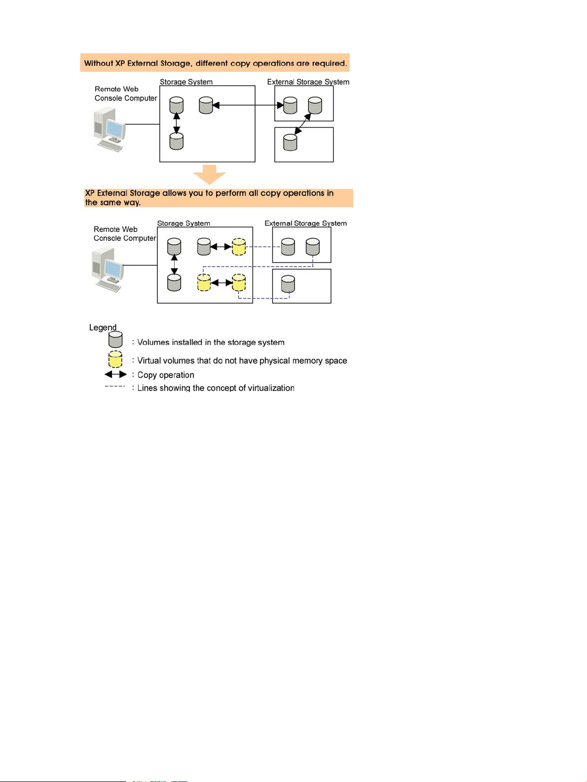
Figure 1 Unifying Copy Operations between Different Storage Systems
Unifying Connections from a Host to Different Storage Systems
When a system has multiple storage systems, a host usually needs to connect all storage systems.
When a system administrator configures the connections from a host to volumes, they need to
follow the different instructions depending on the storage systems.
If you install XP External Storage, a system administrator only needs to configure the connection
from a host to the XP storage system. After the configuration is completed, a host can manipulate
volumes in the external storage system in the same way as volumes in the XP storage system.
10 Overview of HP StorageWorks XP External Storage Software
Page 11
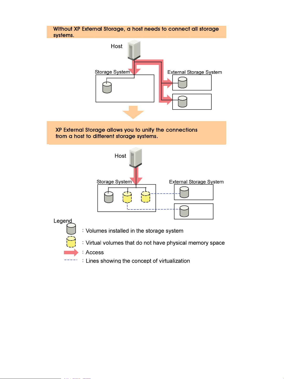
Figure 2 Unifying Connections from a Host to Different Storage Systems
Unifying Connections from a Host to Different Storage Systems 11
Page 12

2 About XP External Storage Operations
This chapter explains the functions and the applications of XP External Storage.
• “Connecting External Storage Systems” (page 12)
• “XP External Storage Components” (page 13)
• “XP External Storage Operations” (page 15)
• “Configuring XP External Storage” (page 16)
• “Choosing Mapping Policy” (page 26)
• “Using a Mapped External Volume from a Connected Host” (page 27)
• “Interoperability with other Products and Functions” (page 29)
• “Examples of Using External Volumes with Other Products” (page 31)
Connecting External Storage Systems
XP External Storage enables you to use HP XP storage systems and other vendors' storage systems
(such as IBM or EMC) as connectable external storage systems. Hosts will recognize these volumes
as internal volumes of the original XP storage system. From this section onward, the original storage
system is called local storage system and a connected storage system is called the external storage
system.
External volume mapping is required for manipulating external volumes from a local storage system.
Mapping means assigning management numbers to the external volumes. These management
numbers are required for manipulating external volumes from a local storage system. By assigning
management numbers to the external volumes, the system administrator will be able to manipulate
not only internal volumes of a local storage system but also external volumes using Remote Web
Console. The management numbers consist of external volume group number - sequential number
(for example, E2-1, E50-3).
Figure 3 (page 13) shows the concept of a local storage system and an external storage system
that are connected by XP External Storage. In the figure, the external storage system is connected
to the external port of the local storage system via a switch using the Fibre Channel interface. The
external port is a kind of port attribute that is used for XP External Storage. The external volumes
are mapped as internal volumes.
12 About XP External Storage Operations
Page 13
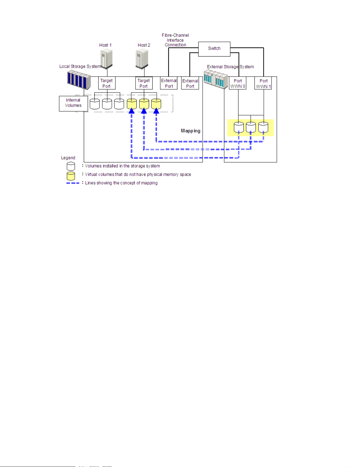
Figure 3 Concept of XP External Storage
By mapping an external volume as an internal volume using XP External Storage as shown in
Figure 3 (page 13), it becomes possible to operate the external volume using Remote Web Console
as if it is a volume in the local storage system.
XP External Storage Components
Systems using XP External Storage usually contain the following components:
• Local storage system
• External storage system
• Remote Web Console computer
• XP External Storage
• External volume
• Internal volume, which is a virtual representation of an external volume
• LDEVs (Logical Devices) in an external volume
• Cross-subsystem path
• Mapping path
Figure 4 (page 14) illustrates the relations of the XP External Storage components.
XP External Storage Components 13
Page 14
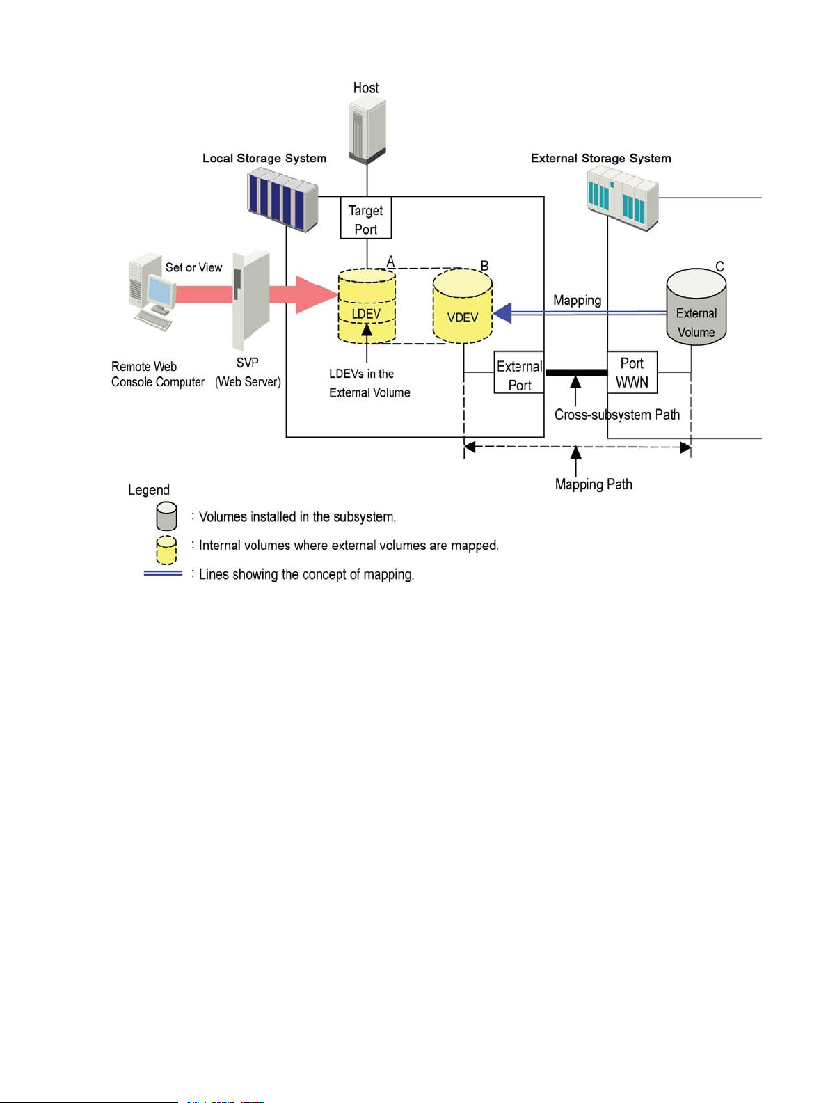
Figure 4 XP External Storage Components
This section describes the details on the storage systems, cross-subsystem paths, volumes and
mapping paths as shown in Figure 4 (page 14).
Storage Systems and Cross-subsystem Paths
Before using XP External Storage, connect the Fibre Channel port of the local storage system to
the external storage system port with the fiber cable. The route between the ports that are connected
with the cable, is called the cross-subsystem path.
The Fibre Channel port of the local storage system is set to connect to a host by default. The Fibre
Channel port can be connected to an external storage system if you change the attribute of the
Fibre Channel port to make it an external port. The external storage system port can be a target
port, that is, a port that would be connected to a host if the storage system were not being used
as external storage.
Two or more external storage systems can be connected to one external port. You can add an
external storage system to a port that is being used by another external storage system.
To manipulate XP External Storage, you need to install XP External Storage using the license key.
Use your Remote Web Console computer to access the local storage system via SVP (web server)
and perform the XP External Storage operations.
Volumes and Mapping Paths
Volumes in the external storage system (see C in Figure 4 (page 14)) are called external volumes.
Mapping is necessary to manipulate an external volume from the local storage system. The system
administrator maps an external volume as an internal volume (see B in Figure 4 (page 14)) in the
14 About XP External Storage Operations
Page 15

local storage system. After the mapping, you can manipulate the external volume from the local
storage system in the same way as manipulating an internal volume.
When external volumes in external storage systems are mapped as internal volumes in your storage
systems, the external volumes can be accessed and copied by hosts connecting to your storage
systems, but not by hosts connecting to the external storage systems.
This document sometimes uses the term external volume or mapped external volume to mention an
internal volume where an external volume is mapped (see B in Figure 4 (page 14)), because this
internal volume is a virtual representation of an external volume.
When you perform mapping, a path is automatically created between an internal volume and an
external volume. This path is called a mapping path, which connects one volume with another
volume. A cross-subsystem path is a part of a mapping path.
To use the external volumes that you mapped as an internal volume (see B in Figure 4 (page 14))
- from the host or other program products, the system administrator needs to create LDEVs in the
external volume (see A in Figure 4 (page 14)). To create LDEVs, use XP External Storage at the
time of mapping, or use the Virtual LVI/LUN (VLL) function on the internal volume where an external
volume is mapped after mapping. The LDEVs created by these methods are called LDEVs in the
external volume in this document. These LDEVs are usually called external volumes in other
documents.
An external volume corresponds to a VLL VDEV (Virtual Device). An LDEV in the external volume
corresponds to a VLL LDEV. Therefore, you can use the VLL function to create custom-sized volumes
in an external volume after mapping, in the same way as creating custom-sized volumes in the
normal internal volumes. For details on VDEVs and LDEVs, see the HP StorageWorks
XP24000/XP20000 Virtual LVI/LUN (VLL) and Volume Shredder User Guide.
XP External Storage Operations
Use XP External Storage to execute the following operations.
• Preparing to use external volumes
You can map external volumes, set port attributes, and set cross-subsystem paths. For details,
see “Configuring XP External Storage” (page 16) and “Overview of Setting Operations”
(page 65).
• Preparing to manipulate the power supply of the storage systems
You must follow specific procedures to manipulate the power supply of the storage systems
when external volumes are used. To turn on or off the power supply of the external storage
system after starting to use the external volumes, you need to execute the commands of XP
External Storage. For details, see “Turning On or Off the Storage System” (page 88).
• Setting up and removing the cross-subsystem paths
When you set up or remove the path (cable) connecting the storage systems, you need to use
XP External Storage to make settings on the path. For details on removal, see “Disconnecting
External Storage System or Disconnecting External Volume” (page 91) and “Checking
Connection Status and Resuming External Volume Operation” (page 93). For details on setup,
see “Configuring the Cross-subsystem Path” (page 81).
• Referring to the status of external volumes
You can see the status and the configuration of external volumes. For details, see “Checking
the External Volume Details” (page 85).
• Stopping the use of external volumes
You can cancel mapping of external volumes. For details, see “Deleting the External Volume
Mapping (Delete Volume Command)” (page 99).
XP External Storage Operations 15
Page 16

• Using spreadsheets to map external volumes
XP External Storage supports Configuration File Loader spreadsheets. These spreadsheets
allow you to configure the mapping of multiple external volumes at the same time, which is
efficient when mapping large numbers of volumes. For details, see “Using Spreadsheets for
XP External Storage Operations” (page 101).
• Setting the remote command device
By using the remote command device, you can manipulate volumes in the external storage
system from RAID Manager on host computers. For details, see “Remote Command Devices”
(page 119).
Configuring XP External Storage
Before configuring the XP External Storage settings, answer the following:
• Which ports can be connected to external storage systems? (see “Choosing the External Port”
(page 16))
• Which external storage system and volumes should be mapped as the internal volumes? (see
“Choosing and Mapping External Volumes” (page 16))
• How will you configure external volume groups? (see “Registering a Volume to an External
Volume Group (ExG)” (page 17))
• What external volume attributes will be configured? (see “Configuring External Volume
Attributes” (page 17)).
• How will you configure cross-subsystem paths? (see “Cross-subsystem Paths” (page 18))
• How will you make volumes usable from the local storage system? (see “Connecting Mainframe
Volumes” (page 25) and “Connecting Open Systems Volumes” (page 26))
Each item is explained in the following sections.
Choosing the External Port
The port used for XP External Storage must be set as the external port. When the external storage
system is connected to the external port of the local storage system, you can view the information
on the external storage system from the Remote Web Console computer. The external storage
system cannot be connected to ports other than the external port.
In order to set the port attribute to external, any LU paths set to the port must be released. The
attribute of the port where LU paths are already set cannot be changed to external. Therefore, you
must identify ports whose attributes can be changed to external before starting the XP External
Storage operations.
The ports whose attributes are set for remote copy software (for example, RCU target, initiator) or
other features cannot be used as external ports for XP External Storage. In addition, change the
port attribute to external if the port attribute is set to other than external.
For instructions on configuring port attributes, see “Setting Port Attribute for Local Storage System”
(page 67).
Choosing and Mapping External Volumes
When connecting an external storage system to an external port, volumes in the external storage
system (external volumes) become available for mapping as volumes in the local storage system
16 About XP External Storage Operations
Page 17

(internal volumes). Identify the volumes in each external storage system that should be mapped as
internal volumes.
• You cannot access the data that is stored in an external volume beyond the maximum available
capacity.
For example, if an external volume of 100 GB was mapped as an internal volume of 70 GB,
then 30 GB of the external volume would not be accessible from the local storage system side.
• You cannot map an external volume whose capacity is smaller than the minimum available
capacity.
For example, you cannot map an external volume of 10 GB as an internal volume requiring
at least 30 GB.
The maximum or minimum available capacity of an external volume depends on the emulation
type that is set when the volume is mapped. See “Required Volume Capacity for Each Emulation
Type” (page 152) for the capacity of the external volume for each emulation type. For the maximum
number of external volumes that can be mapped, see “XP External Storage Requirements” (page 37).
Registering a Volume to an External Volume Group (ExG)
When you map an external volume as an internal volume, you need to register the external volume
to an external volume group.
External volumes, which are set by XP External Storage, can be classified into groups by usage.
Any group of this type is called an external volume group (ExG). For instance, you can register
multiple volumes in one external storage system to one external volume group. Or you can register
the volumes in one external volume group and manage them in block, even though the data you
want to manage in a lump is stored in volumes in the different external storage systems.
You need to assign numbers to external volume groups. See “XP External Storage Requirements”
(page 37) for details on a maximum number of external volume groups, or a maximum number of
volumes to be registered in one external volume group.
Configuring External Volume Attributes
When you map an external volume as an internal volume, you set the attributes of the external
volume. External volume attributes can be set using the mapping policy or the Set External Volume
Parameter dialog box of XP External Storage. For details on the mapping policy, see “Choosing
Mapping Policy” (page 26). For details on the Set External Volume Parameter dialog box, see
“Set External Volume Parameter Dialog Box” (page 72).
The attributes of the external volume are as follows:
• Emulation type
Select an emulation type for the mapped external volume from the list.
The emulation type OPEN-V must be selected if, after the mapping, you are planning to use
the existing data in the external volume from the local storage system. For example, to migrate
the existing data in the external volume to the local storage system volume, set the OPEN-V
emulation type when the external volume is mapped.
If you select the emulation type other than OPEN-V, the volume requires a specific area to be
provided for management data. Once this area is provided, volume capacity after the mapping
becomes less than the actual external volume capacity for the area (volume). For details on
volume capacity, see “Capacity Guidelines” (page 40).
• Cache Mode (Enable or Disable)
Cache mode specifies whether the write data from the host to the external storage system is
propagated synchronously (Disable) or asynchronously (Enable). By default, cache mode is
Configuring XP External Storage 17
Page 18

set to Disable. All I/O to and from the local storage system (either Enable or Disable) always
uses cache mode. Write operations are always backed up in duplex cache.
◦ If you select Enable, after receiving the data into the local storage system cache memory
, the local storage system signals the host that an I/O operation has completed and then
asynchronously destages the data to the external storage system.
◦ When emulating OPEN volumes and selecting Disable, the local storage system signals
the host that an I/O operation has completed only after the local storage system has
synchronously written the data to the external storage system. When emulating mainframe
volumes, when you select Disable, after receiving the data into the local storage system
cache memory, the local storage system signals the host that an I/O operation has
completed and then asynchronously destages the data to the external storage system.
If you perform the Cache Residency Manager operation on an external volume with
Cache Mode set to Disable, the bind mode of Cache Residency Manager cannot be
specified. For Cache Residency Manager operations, see the HP StorageWorks
XP24000/XP20000 Cache Residency Manager User Guide.
When you set the cache mode, note the following:
◦ Data that is not written by the host (for example, data written by HP StorageWorks XP
Continuous Access Software) is asynchronously destaged to the external storage system
regardless of the Cache Mode setting.
◦ If you set the emulation type for a mainframe system (such as 3390-x), data that is written
by a host using a command such as Format Write is asynchronously destaged to the
external storage system regardless of the Cache Mode setting. Data that is written by a
host using a command such as Update Write is destaged to the external storage system
as configured in the Cache Mode setting.
• Inflow Control (Enable or Disable)
Inflow control specifies whether the writing operation to the cache memory is stopped (Enable)
or continued (Disable) when the writing operation to the external volume is impossible. By
default, inflow control is set to Disable.
◦ If you select Enable, the writing operation to cache is stopped and the I/O from the host
is not accepted when the writing operation to the external volume is impossible.
◦ If you select Disable, the I/O from the host during the retry operation is written to the
cache memory even after the writing operation to the external volume is impossible. Once
the writing operation to the external volume becomes normal, all the data in the cache
memory is written to the external volume (all the data is destaged).
• CLPR
When the cache memory is partitioned using HP StorageWorks XP Disk/Cache Partition
Software, configure a cache logical partition (CLPR) to access the mapped volume. It is strongly
recommended that you place External Storage array groups in a CLPR other than CLPR0. See
the HP StorageWorks XP24000/XP20000 Disk/Cache Partition User Guide for detailed
information on CLPR.
Cross-subsystem Paths
A cross-subsystem path is a route from a local storage system port to an external storage system
port. To prepare for possible failures of the cable, the switch, or the channel processor, HP
recommends that you create redundant cross-subsystem paths. This redundancy allows you to
continue performing the I/O operations to the external volumes when you maintain the cable. You
can set up to eight paths.
18 About XP External Storage Operations
Page 19

If two or more external volumes use the same redundant cross-subsystem paths, these external
volumes can be a group. This group is called a path group. In the redundant cross-subsystem paths,
the cross-subsystem path that has the highest priority is called the primary path. The cross-subsystem
paths other than the primary path are called alternate paths.
• Setting of the path groups
A path group is automatically set when you map the external volume or when you change a
path group by using spreadsheets. You cannot set a new path group by itself. For more
information about changing a path group by using spreadsheets, see “Changing Path Group”
(page 115).
• Setting of cross-subsystem paths
Use fiber cables to establish multiple paths between the external storage system and the local
storage system. At this time, connect to the external storage system from a different cluster
port of the local storage system.
If multiple paths are established between the two storage systems, the starting points of the
paths (that is, external ports of the local storage system) and the ending points (that is, WWNs
showing the ports of the external storage system) will be displayed in a dialog box when you
map an external volume. In this dialog box, you can set cross-subsystem paths by selecting
the starting points and the ending points of the paths according to the actual cable connections.
For details on how to set cross-subsystem paths, see “Configure Cross-subsystem Paths Dialog
Box” (page 79).
• Setting of redundant cross-subsystem paths
Path Mode
Path mode is either Single mode or Multi mode, depending on the connected external storage
system.
• In the Single mode, only the path with the highest priority (primary path) is used to execute
• In the Multi mode, all of the set paths are used at the same time. The multiple paths are used
For example, when a volume in the external storage system with the path mode of the Single mode
is mapped as an internal volume using XP External Storage, the host I/O operations to the external
volume are enabled using the primary path set in the mapping operation. The path is automatically
switched to the alternate path when the primary path set in mapping operation cannot be used
due to, for instance, maintenance operation in the storage system, or a failure in the channel
processor. Because the path is switched to the alternate path, the I/O operation to the external
volume continues even though an error occurred in the original path.
When the primary path cannot be used for three minutes continuously, the path is switched to the
alternate path.
You can set redundant cross-subsystem paths (add alternate paths) when you set the
cross-subsystem paths. You can also add an alternate path or change the priority after
completing the mapping of the external volume (see “Setting the Cross-subsystem Paths”
(page 78)).
the I/O to the external volume. When an error occurs in the primary path, the path with the
second highest priority is used.
to execute the I/Os to the external volume thus distributing the work load (round-robin
processing).
Examples of Alternate Paths
Figure 5 (page 20) illustrates an example of setting an alternate path. External storage system
ports, WWN A and WWN B, are connected to CL1-A and CL2-A respectively, which are set to
the external ports in the local storage system. You need to specify the port of a different cluster in
Configuring XP External Storage 19
Page 20
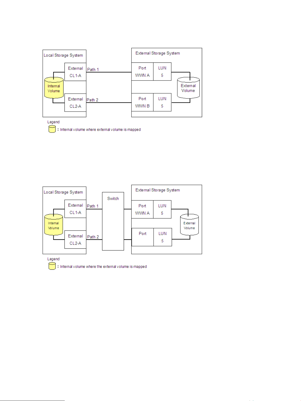
the local storage system for the alternate path. Therefore, CL1 port and CL2 port are specified as
shown in the figure.
Figure 5 Example of Alternate Path Setting
Figure 6 (page 20) illustrates an example of setting an alternate path when a switch is used. Two
ports are specified in the local storage system, and connected to the ports in the external storage
system through the switch. In this case, two ports of different clusters are specified in the local
storage system. Therefore, the setting of the alternate path is enabled.
Figure 6 Example of Available Alternate Path Setting
In Figure 7 (page 21), two paths are also set between the internal volume and the external volume.
However, one port is specified in the local storage system, and two ports are specified in the
external storage systems over the switch. This configuration is not recommended because two ports
of different clusters need to be set in the local storage system for alternate path settings in XP
External Storage.
20 About XP External Storage Operations
Page 21
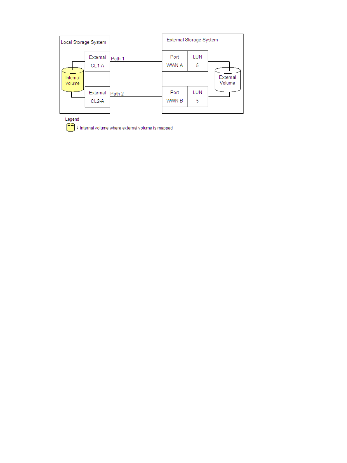
Figure 7 Example of Unavailable Alternate Path Setting
Examples of Switching I/O Execution Paths to Alternate Paths
This section describes examples of the performance when the I/O execution path is switched to
the alternate path for each path mode as follows:
• When the path mode is Multi mode
• When the path mode is Single mode
• When the path mode is Single mode and there is at least one alternate path in the Standby
status
For the description about the path status, see “Mapping Path Information Dialog Box” (page 86).
• When the path mode is Multi mode
Figure 8 (page 22) shows an example of when the path mode is Multi mode. When an error
occurs in one path, I/Os are executed using the paths other than the error path.
As you restore the error path, the use of the restored path is automatically resumed.
Configuring XP External Storage 21
Page 22
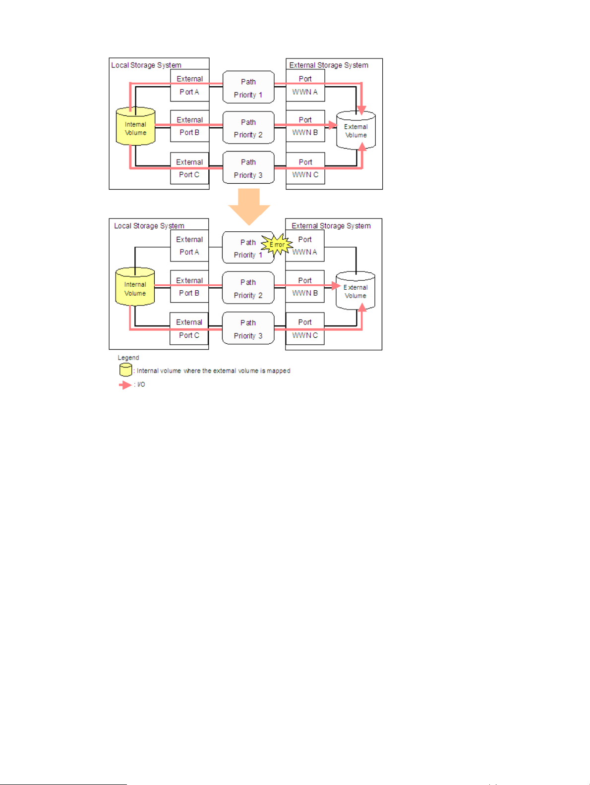
Figure 8 When the Path Mode is Multi Mode
• When the path mode is Single mode
Figure 9 (page 23) shows an example of when the path mode is Single mode. When an error
occurs in the path that is being used for I/Os, the I/O execution path is switched to the path
with the second highest priority.
As you restore the path with the priority higher than the currently used path, the I/O execution
path is automatically switched to the restored path that has the highest priority.
22 About XP External Storage Operations
Page 23
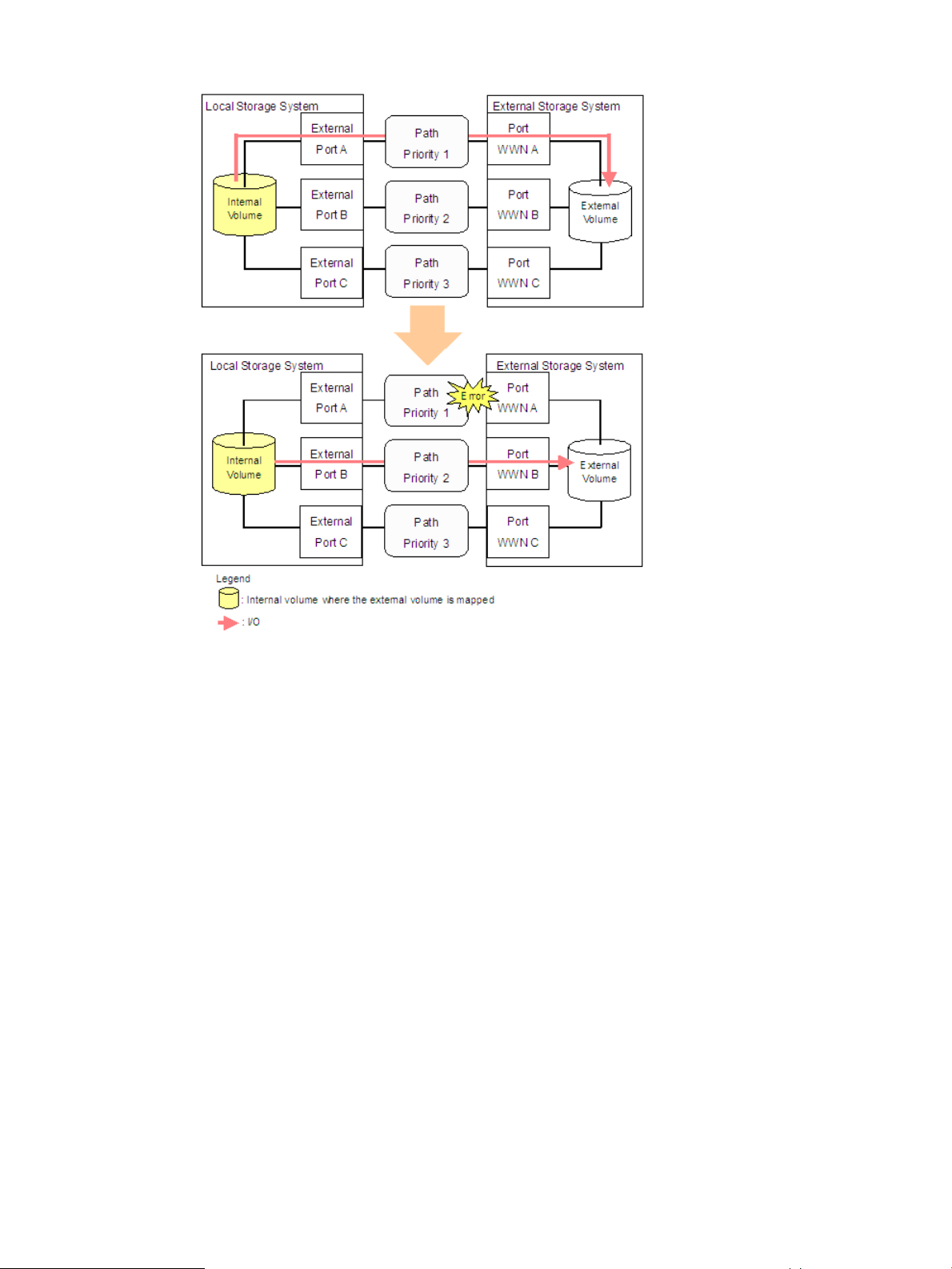
Figure 9 When the Path Mode is Single Mode
• When the path mode is Single mode and there is at least one alternate path in the Standby
status
Figure 10 (page 24) shows an example of when the path mode is Single mode, and there
are alternate paths in Normal status and Standby status. Figure 11 (page 25) shows another
example of when the path mode is Single mode. For Figure 11 (page 25), there are alternate
paths in Standby status only.
When an error occurs in the path that is being used for I/Os, the I/O execution path is
switched to the path with the second highest priority in Normal status (see Figure 10 (page
24)). If there is no path in Normal status other than the path that is being used for I/Os, the
status of the path in Standby status is automatically changed to Normal, and the I/O execution
path is switched to that path (see Figure 11 (page 25)).
As you restore the path with the highest priority, note that only when the external storage
system is an EVA storage system, the I/O execution path is switched back to the restored
highest priority path. In this case, the status of the path for which the status was changed to
Normal when the error occurred changes back to Standby.
Configuring XP External Storage 23
Page 24
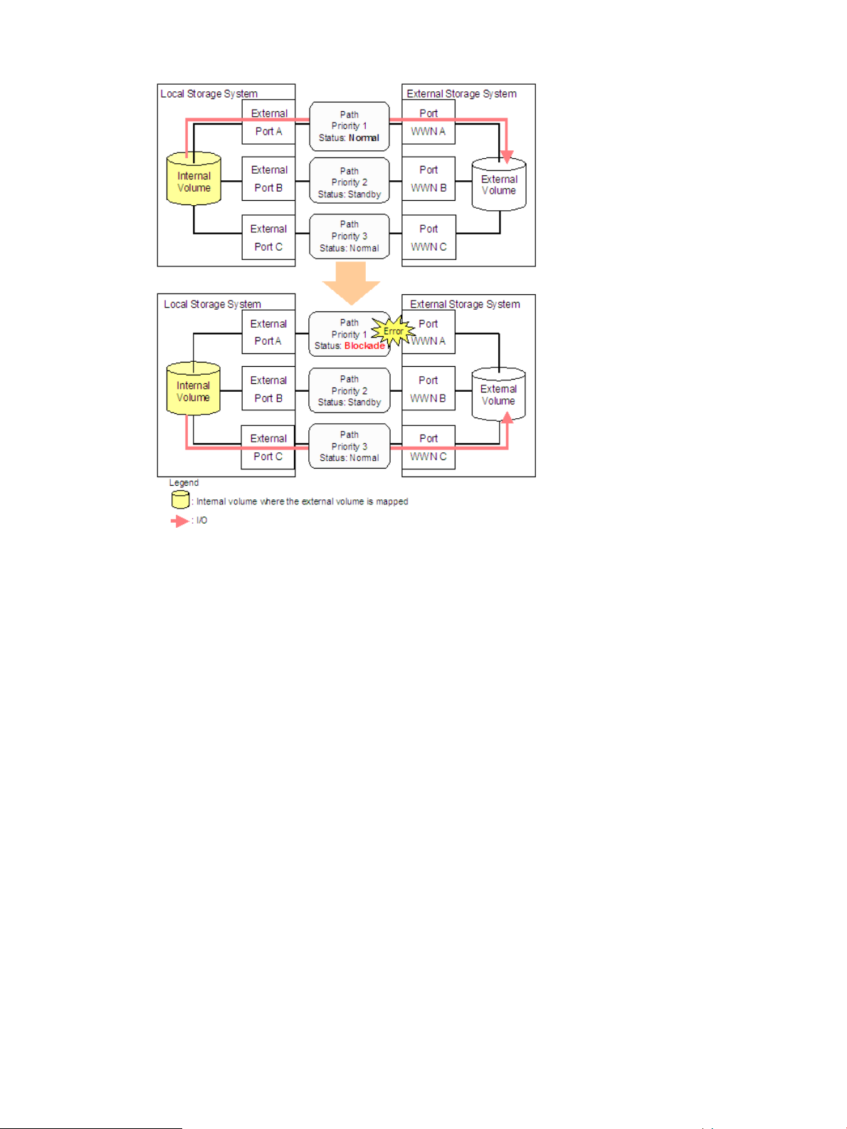
Figure 10 Single Mode with Alternate Paths in Normal and Standby
24 About XP External Storage Operations
Page 25
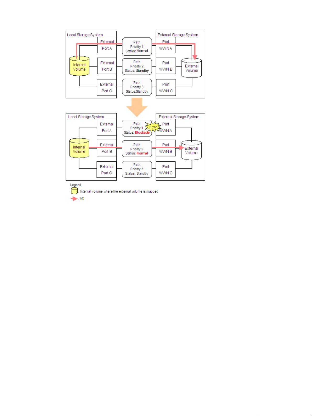
Figure 11 Single Mode with Alternate Paths in Standby Only
Connecting Mainframe Volumes
Mainframe volumes that pre-exist on an external storage system and are accessed by ESCON or
FICON channels cannot connect directly to the storage system as an external volume. The storage
system does not recognize these volumes because of Fibre Channel.
To use external volumes as mainframe volumes, there are two ways:
• Zero-format external volumes on the external storage system side, map the external volumes
to the internal volumes using XP External Storage on the local storage system side, and then
perform the Write to Control Blocks operation using the VLL function on the local storage system
side.
• Map the external volumes to the internal volumes using XP External Storage on the local storage
system side, and then format the mapped external volumes using the VLL function on the local
storage system side.
If you set the emulation type for the mainframe system (such as 3390) as you map the external
volume, the status of the mapped volume becomes Blockade after the mapping operation. After
the system administrator performs the Write to Control Blocks operation or formats the mapped
external volumes using the VLL function on the local storage system side, the mainframe host can
then access the new mainframe volume through the local storage system's ESCON or FICON
channels.
If you format the mapped volume of the external storage system from the external storage system
side, the existing data before formatting cannot be assured. When you use the mapped external
volume from the mainframe operating system, format the mapped volume from the local storage
system side.
Configuring XP External Storage 25
Page 26

For the volume formatting and Write to Control Blocks operation procedures, see the HP
StorageWorks XP24000/XP20000 Virtual LVI/LUN (VLL) and Volume Shredder User Guide.
Connecting Open Systems Volumes
Open systems volumes in external storage system connect to and are recognized by the storage
system as open systems volumes, without requiring reformatting. Reformatting is not required
because the connection between the storage system and the external storage system is Fibre
Channel. If you need to initialize the data area for the volume, format the volume using the VLL
function. For the volume formatting operation procedure, see the HP StorageWorks
XP24000/XP20000 Virtual LVI/LUN (VLL) and Volume Shredder User Guide.
OPEN-V emulation is recommended because, in most cases, OPEN-V emulation provides the most
efficient use of storage and the best performance. Also, emulation types other than OPEN-V may
not retain existing data after being mapped.
Choosing Mapping Policy
Mapping policy is a list of settings of the necessary information for mapping the external volume.
By setting the mapping policy in advance, the setting at the time of mapping will be easier.
The default mapping policy is prepared in advance. You can change the values of the default
mapping policy.
Difference between Automatic Mapping and Manual Mapping
When you map the external volume, you need to configure:
• Cross-subsystem paths
• External volume parameters
• LDEV number to LDEVs in the external volume
• SSID (storage system ID)
When you perform automatic mapping, users configure only cross-subsystem paths and all the
other settings are automatically made by XP External Storage according to the mapping policy.
When you perform manual mapping, users configure all the settings.
Automatic mapping maps all the external volumes found by volume discovery to internal volumes.
Automatic mapping requires fewer settings but you are not allowed to set different parameters for
each external volume or to specify an LDEV number for each LDEV. You can set the parameters
such as emulation type to the mapping policy in advance.
NOTE: In automatic mapping, external volumes are mapped in the order of the local storage
system recognizing. Therefore, the LDEV number is also specified in this order. Moreover, when
you copy external volumes with the program product for copying, the copy operation is performed
in the order of the LDEV number if you specify two or more external volumes for the initial copy or
resynchronization. Therefore, when you copy external volumes that are mapped automatically with
the program product for copying, the copy operation might focus on a specific RAID group and
cause insufficient performance. To prevent the copy operation from focusing on a specific RAID
group, HP recommends that the external volumes be mapped manually so that the copy operation
is distributed to two or more RAID groups.
Port Discovery and Volume Discovery
Port discovery and volume discovery are methods used to find external volumes, and are executed
when you map external volumes or when you add cross-subsystem paths.
• Port discovery searches for and gets information about target ports of the connected external
storage system from an external port of the local storage system. The latest information about
26 About XP External Storage Operations
Page 27

the external storage system can be displayed in a dialog box of XP External Storage when
you execute port discovery.
You can set in advance the mapping policy on whether to execute port discovery automatically
or manually. If port discovery is executed automatically, WWNs connected to all the external
ports of the local storage system will be searched for. If port discovery is executed manually,
you can select a specific external port and limit the scope to search WWNs. If you can specify
which external port to search for, you can reduce the operation time by executing the port
discovery manually.
• Volume discovery searches for and gets information about external volumes from the target
ports of the external storage system. Volume discovery is automatically executed after the port
discovery process.
When a port in an external storage system is connected to an XP storage system and has a
management LU (for example, Universal Xport LU), an extra operation is required. A management
LU is an LU that receives commands issued by a particular application. The management LU controls
or manages that application. The management LU stores control information from that application
and, therefore, the management LU cannot be used as an external volume. A command device is
not a management LU.
Before performing port discovery or volume discovery, perform one of the following operations on
the external storage system.
• Delete the management LU from the port connected to the XP storage system.
• Make sure that at least one LU is used for data storage and has a smaller LUN ID than the
LUN of the management LU. Also make sure that the data storage LU is set to the port connected
to the XP storage system.
• Use the security function and configure the access attribute of the management LU to prohibit
read and write operations.
If none of the operations is performed, an external storage system that has a management LU might
not be recognized by the local storage system.
Using a Mapped External Volume from a Connected Host
There are two ways of using the mapped external volume from a host that is connected the local
storage system.
• “Storing New Data in the Mapped External Volume” (page 27)
• “Using Existing Data in the Mapped External Volume” (page 28)
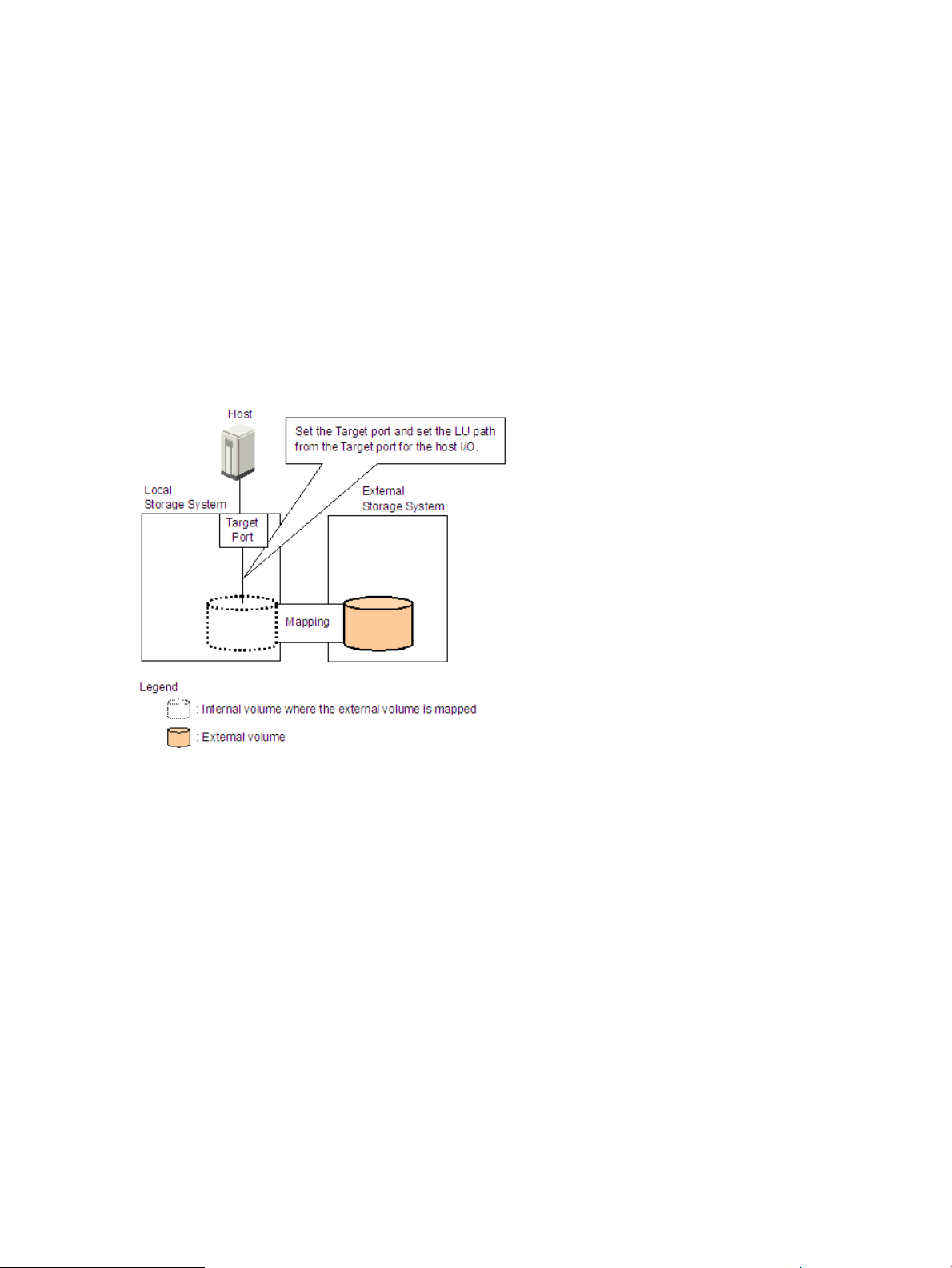
Storing New Data in the Mapped External Volume
To store new data in a mapped external volume from a host that is connected to the local storage
system:
1. Map the volume in the external storage system as an internal volume of the local storage
system using XP External Storage.
Select the emulation type of the mapped volume as you required. If you select the emulation
type for the open system (such as OPEN-V), go to step 2. If you select the emulation type for
the mainframe system (such as 3390-3), go to step 3.
For information on mapping operations, see “Mapping an External Volume Automatically”
(page 67).
2. If you set the emulation type for the open system when you map the volume, the status of the
mapped volume automatically becomes Normal. If you need to initialize the data area of the
mapped volume, format the volume using the VLL function. For the volume formatting procedure,
Using a Mapped External Volume from a Connected Host 27
Page 28
see the HP StorageWorks XP24000/XP20000 Virtual LVI/LUN (VLL) and Volume Shredder
User Guide.
Go to step 4.
3. If you set the emulation type for the mainframe system when you map the volume, the status
of the mapped volume becomes Blockade. Format the volume using the VLL function.
For zero-formatted external volumes, when you select that volume to map, you can use the
VLL function to perform the Write to Control Blocks operation to restore the volume. For
instructions on how to format volumes and the Write to Control Blocks operation, see the HP
StorageWorks XP24000/XP20000 Virtual LVI/LUN (VLL) and Volume Shredder User Guide.
Go to step 4.
4. To perform the host I/O operations, set the LU path from the Target port to the mapped volume.
After the LU path is set, the host I/O operation to the mapped volume becomes available.
Figure 12 Storing the New Data in the Mapped External Volume
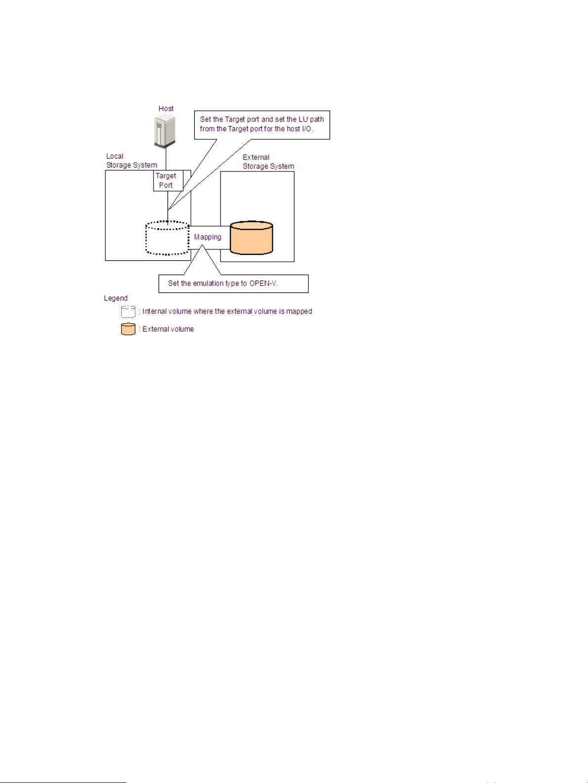
Using Existing Data in the Mapped External Volume
To use the existing data in the mapped external volume from the host that is connected to the local
storage system:
1. Store the data from the host that is connected to the external storage system to the volume in
the external storage system.
2. Map the volume containing data in the external storage system as an internal volume of the
local storage system using XP External Storage.
When you map the external volume, set the attributes of the mapped volume to Emulation
type = OPEN-V to read the existing data in the mapped external volume from the local storage
system side.
3. Set the LU path from the Target port to the mapped volume to perform the host I/O operation.
After the LU path is set, the host I/O operation to the mapped volume can be initiated.
Make sure that you do not access the external volume, which has been mapped as an internal
volume, from the host that is connected to the external storage system. Also make sure that you do
not access the mapped external volume using the function (for example, copy function) of the
external storage system. Once you have mapped an external volume as an internal volume, you
can access the mapped external volume only from the local storage system side.
28 About XP External Storage Operations
Page 29
From the host, you can access the external storage system volumes that have not been mapped as
internal volumes. There is no restriction. Figure 13 (page 29) illustrates using existing data in a
mapped external volume.
Figure 13 Using the Existing Data in the Mapped External Volume
Interoperability with other Products and Functions
You can use XP disk array program products to use and manage the external volumes you have
set using XP External Storage. For the operations and notes on each program product, see the
respective user's guides.
LUN Manager and Configuration File Loader
If you set the emulation type for the open system as you map an external volume, you need to set
the LU path for the mapped volume using LUN Manager.
Consider the following for the Configuration File Loader function:
• You can set the LU path definition for the external volume (add, delete, or change LU paths).
• You can set the command device for the external volume (add or delete the setting).
• The setting of the channel adapter (CHA) mode, host group, and WWN for the external port
is not supported. When an external volume is mapped through that external port, the setting
operation of the topology is not available, either.
LUN Expansion (LUSE)
Consider the following for LUN Expansion (LUSE):
• The internal volume in the local storage system and the external volume cannot be combined
to form a LUSE volume.
• Do not combine LDEVs of multiple external volumes to create a LUSE volume. Only the LDEVs
in the same external volume can be used to configure the LUSE volumes.
• All external volumes in a LUSE volume must be in the same Cache Mode.
Interoperability with other Products and Functions 29
Page 30

Virtual LVI/LUN (VLL)
Consider the following for Virtual LVI/LUN (VLL):
• If you set the emulation type for the mainframe system as you map the external volume, you
need to format the mapped volume or perform the Write to Control Blocks operation using the
VLL function before you use the external volume.
For the volume formatting operation and Write to Control Blocks operation procedures, see
the HP StorageWorks XP24000/XP20000 Virtual LVI/LUN (VLL) and Volume Shredder User
Guide.
• If you create LDEVs in an external volume using the VLL function, the cache mode of the created
LDEVs becomes the same as that of the source external volume.
Cache Residency Manager
Consider the following for Cache Residency Manager:
• The bind mode of the Cache Residency Manager operation cannot be specified for the external
volume if the Cache Mode is set to Disable.
• If you use the mapped external volume for the Cache Residency Manager operation and set
the bind mode, a cache of twice as much capacity as the user data is required for the Cache
Residency Manager operation.
Performance Monitor and XP Auto LUN
Consider the following for Performance Monitor and XP Auto LUN:
• Performance Monitor can be used to display the monitoring information about the external
volumes.
• Mapped volumes can be used for XP Auto LUN. For instructions on adjusting volume capacity,
see “Adjusting the Volume Capacities for Pairs” (page 156).
For the configuration example of XP Auto LUN, see “XP Auto LUN Operations” (page 31).
XP Continuous Access and Hitachi TrueCopy™ for Mainframe
Mapped volumes can be used for XP Continuous Access and for TrueCopy for Mainframe. For a
configuration example of XP Continuous Access, see “XP Continuous Access Operations” (page 32).
HP StorageWorks XP Continuous Access Journal Software and Hitachi Universal Replicator™ for Mainframe
Mapped volumes can be used for XP Continuous Access Journal and Universal Replicator for
Mainframe. For a configuration example of XP Continuous Access Journal, see “XP Continuous
Access Journal Operations” (page 33).
HP StorageWorks XP Business Copy Software and Hitachi ShadowImage™ for Mainframe
Mapped volumes can be used for XP Business Copy and ShadowImage for Mainframe. For a
configuration example of XP Business Copy, see “XP Business Copy Operations” (page 35).
30 About XP External Storage Operations
Page 31

HP StorageWorks XP Snapshot Software
Mapped volumes can be used for XP Snapshot. Consider the following for XP Snapshot:
• Both internal and external volumes cannot be mixed in one pool.
• All external volumes in the same pool must be in the same Cache Mode.
HP StorageWorks XP Thin Provisioning Software
Mapped volumes can be used for XP Thin Provisioning. Consider the following for XP Thin
Provisioning:
• Both internal and external volumes cannot be mixed in one pool.
• All external volumes in the same pool must be in the same Cache Mode.
SNMP Agent
Consider the following for SNMP Agent:
• The information on the mapped external volume is displayed.
• The information on the external port is displayed.
Examples of Using External Volumes with Other Products
For the following XP disk array program products, examples of using external volumes are described
in the following subsections:
• “XP Auto LUN Operations” (page 31)
• “XP Continuous Access Operations” (page 32)
• “XP Continuous Access Journal Operations” (page 33)
• “XP Business Copy Operations” (page 35)
• “XP Snapshot Operations” (page 36)
XP Auto LUN Operations
Figure 14 (page 32) shows the use of an external volume for the XP Auto LUN operation. The
mapped external volume is set as the source volume and the local internal volume is set as the
target volume. Existing data in the external volume is migrated manually to the local storage system
internal volume using XP Auto LUN. For detailed information on XP Auto LUN operations, see the
HP StorageWorks XP24000/XP20000 Auto LUN Software User Guide.
The procedure for the operation is as follows:
1. Use XP External Storage to map a volume in the external storage system as an internal volume
of the local storage system.
For Figure 14 (page 32), set the attributes of the mapped volume as follows:
Emulation type: OPEN-V
To migrate the existing data in the mapped external volume to the local storage system volume
using XP Auto LUN, set the emulation type to OPEN-V as you map the volume. The emulation
type must be OPEN-V to read out the existing data in the external volume from the local storage
system side.
Examples of Using External Volumes with Other Products 31
Page 32

To copy the existing data in the mapped external volume using the copy program products
of Remote Web Console such as XP Continuous Access and XP Business Copy, the emulation
type of the mapped external volume also has to be OPEN-V.
2. Prepare the local internal volume that has the same capacity as the mapped external volume.
Adjust the capacity of the internal volume as it is required using the VLL function.
For the VLL function, see the HP StorageWorks XP24000/XP20000 Virtual LVI/LUN (VLL) and
Volume Shredder User Guide.
The emulation type of the prepared internal volume must be OPEN-V.
3. Set the mapped external volume as the source volume and local storage system internal volume
as the target volume.
4. Migrate the existing data in the mapped external volume to the local storage system internal
volume manually using XP Auto LUN.
Figure 14 Example of the XP Auto LUN Operations
XP Continuous Access Operations
Figure 15 (page 33) shows the use of an external volume for the XP Continuous Access operation.
The mapped external volume is set as the S-VOL of the XP Continuous Access pair, and the volume
in the local storage system that is connected as the multipoint control unit (MCU) is set as the P-VOL
of the XP Continuous Access pair. For details on XP Continuous Access, see the HP StorageWorks
XP24000/XP20000 Continuous Access Software User Guide.
The procedure for the operation is as follows:
1. Use XP External Storage to map a volume in the external storage system as an internal volume
of the local storage system, which is used as remote control unit (RCU) for the XP Continuous
Access operation.
You can select the emulation type of the mapped volume as you required. If you select the
emulation type for the open system (such as OPEN-V), go to step 2. If you select the emulation
type for the mainframe system (such as 3390-3), go to step 3.
For details on the mapping operation, see “Mapping an External Volume Automatically”
(page 67).
2. If you set the emulation type for the open system when you map the volume, the status of the
mapped volume automatically becomes Normal. However, the volume formatting processing
32 About XP External Storage Operations
Page 33

is not executed automatically. If you need to format the mapped volume, format the volume
using the VLL function.
For the volume formatting operation procedure, see the HP StorageWorks XP24000/XP20000
Virtual LVI/LUN (VLL) and Volume Shredder User Guide.
Go to step 4.
3. If you set the emulation type for the mainframe system when you map the volume, the status
of the mapped volume becomes Blockade. Format the volume using the VLL function. Or if
you have mapped the volume for which the data area has already been zero-formatted on
the external storage system side, perform the Write to Control Blocks operation using the VLL
function to restore the volume.
For the volume formatting operation and Write to Control Blocks operation procedures, see
the HP StorageWorks XP24000/XP20000 Virtual LVI/LUN (VLL) and Volume Shredder User
Guide.
Go to step 4.
4. Set the P-VOL and S-VOL of the XP Continuous Access pair, as shown in Figure 15 (page 33).
Figure 15 Example of the XP Continuous Access Operations
XP Continuous Access Journal Operations
Figure 16 (page 34) shows the use of an external volume for the XP Continuous Access Journal
operation. The mapped external volume is set as the S-VOL of the XP Continuous Access Journal
pair, and the volume in the local storage system that is connected as the MCU is set as the P-VOL
of the XP Continuous Access Journal pair. For details on XP Continuous Access Journal, see the HP
StorageWorks XP24000/XP20000 Continuous Access Journal Software User Guide.
The procedure for the operation is as follows:
Examples of Using External Volumes with Other Products 33
Page 34

1. Use XP External Storage to map the volume in the external storage system as an internal volume
of the local storage system, which is used as RCU for the XP Continuous Access Journal
operation.
You can select the emulation type of the mapped volume as you required. If you select the
emulation type for the open system (such as OPEN-V), go to step 2. If you select the emulation
type for the mainframe system (such as 3390-3), go to step 3.
For details on the mapping operation, see “Mapping an External Volume Automatically”
(page 67).
2. If you set the emulation type for the open system when you map the volume, the status of the
mapped volume automatically becomes Normal. However, the volume formatting processing
is not executed automatically. If you need to format the mapped volume, format the volume
using the VLL function.
For the volume formatting operation procedure, see the HP StorageWorks XP24000/XP20000
Virtual LVI/LUN (VLL) and Volume Shredder User Guide.
Go to step 4.
3. If you set the emulation type for the mainframe system when you map the volume, the status
of the mapped volume becomes Blockade. Format the volume using the VLL function. Or if
you have mapped the volume for which the data area has already been zero-formatted on
the external storage system side, perform the Write to Control Blocks operation using the VLL
function to restore the volume.
For the volume formatting operation and Write to Control Blocks operation procedures, see
the HP StorageWorks XP24000/XP20000 Virtual LVI/LUN (VLL) and Volume Shredder User
Guide.
Go to step 4.
4. Set the P-VOL and S-VOL of the XP Continuous Access Journal pair, as shown in Figure 16 (page
34).
Figure 16 Example of the XP Continuous Access Journal Operations
34 About XP External Storage Operations
Page 35

XP Business Copy Operations
Figure 17 (page 35) shows the use of an external volume for the XP Business Copy operation. The
mapped external volume is set as the S-VOL of the XP Business Copy pair, and the local storage
system internal volume is set as the P-VOL of the XP Business Copy pair. For details on XP Business
Copy, see the HP StorageWorks XP24000/XP20000 Business Copy Software User Guide.
The procedure for the operation is as follows:
1. Use XP External Storage to map a volume in the external storage system as an internal volume
of the local storage system.
You can select the emulation type of the mapped volume as you required. If you select the
emulation type for the open system (such as OPEN-V), go to step 2. If you select the emulation
type for the mainframe system (such as 3390-3), go to step 3.
For details on the mapping operation, see “Mapping an External Volume Automatically”
(page 67).
2. If you set the emulation type for the open system when you map the volume, the status of the
mapped volume automatically becomes Normal. However, the volume formatting processing
is not executed automatically. If you need to format the mapped volume, format the volume
using the VLL function.
For the volume formatting operation procedure, see the HP StorageWorks XP24000/XP20000
Virtual LVI/LUN (VLL) and Volume Shredder User Guide.
Go to step 4.
3. If you set the emulation type for the mainframe system when you map the volume, the status
of the mapped volume becomes Blockade. Format the volume using the VLL function. Or if
you have mapped the volume for which the data area has already been zero-formatted on
the external storage system side, perform the Write to Control Blocks operation using the VLL
function to restore the volume.
For the volume formatting operation and Write to Control Blocks operation procedures, see
the HP StorageWorks XP24000/XP20000 Virtual LVI/LUN (VLL) and Volume Shredder User
Guide.
Go to step 4.
4. Set the P-VOL and S-VOL of the XP Business Copy pair, as shown in Figure 17 (page 35).
Figure 17 Example of the XP Business Copy Operations
Examples of Using External Volumes with Other Products 35
Page 36

XP Snapshot Operations
Figure 18 (page 36) shows the use of an external volume for the XP Snapshot operation. The
mapped external volume is set as a pool-VOL of the XP Snapshot pair. For details on XP Snapshot,
see the HP StorageWorks XP24000/XP20000 Snapshot User Guide.
The procedure for the operation is as follows:
1. Use XP External Storage to map a volume in the external storage system as an internal volume
of the local storage system.
CAUTION: Set the emulation type of the volume to OPEN-V when you map the volume,
because the volume with the OPEN-V emulation type can only be set as a pool-VOL of XP
Snapshot.
For details on the mapping operation, see “Mapping an External Volume Automatically”
(page 67).
2. The status of the mapped volume automatically becomes Normal. However, the volume
formatting processing is not executed automatically. If you need to format the mapped volume,
format the volume using the VLL function. For the volume formatting operation procedure, see
the HP StorageWorks XP24000/XP20000 Virtual LVI/LUN (VLL) and Volume Shredder User
Guide.
3. Create a pool and add the mapped external volume to that pool as a pool-VOL.
4. Set the P-VOL and S-VOL of the XP Snapshot pair with specifying the pool you have created
at step 3.
Figure 18 Example of the XP Snapshot Operations
36 About XP External Storage Operations
Page 37

3 Preparing for XP External Storage Operations
This chapter describes the requirements and preparations for XP External Storage operations.
• “System Requirements” (page 37)
• “Guidelines for XP External Storage Operations” (page 38)
• “Installing and Uninstalling XP External Storage” (page 44)
• “Starting XP External Storage” (page 45)
System Requirements
The system requirements for XP External Storage are:
• HP XP storage system (First storage system)
All the necessary hardware and microcode required for XP External Storage operations must
be installed and enabled. In this user's guide, the first storage system is called local storage
system.
• Storage system other than the first storage system
A second storage system must be available and operate as an external storage system. The
kinds of storage systems that can be used as an external storage system include HP
StorageWorks EVA storage systems, HP StorageWorks MSA storage systems, and other similar
storage systems. For detailed information on the storage systems that can be used as the
external storage system, see “Storage Systems Supported as External Storage Systems”
(page 37).
• Remote Web Console computer (user-supplied computer)
See the HP StorageWorks XP24000/XP20000 Remote Web Console User Guide for
instructions on installing and using the Remote Web Console computer.
NOTE: You must operate the Remote Web Console computer in Modify mode to perform
XP External Storage operations. Users in View mode can only view XP External Storage
information.
• License key for XP External Storage program product
You need a license key to install XP External Storage.
Storage Systems Supported as External Storage Systems
For the storage systems that are currently supported as external storage, contact HP.
XP External Storage Requirements
Table 1 (page 38) describes the XP External Storage requirements.
System Requirements 37
Page 38

Table 1 XP External Storage Requirements
RequirementItem
1,024 per portMaximum number of ports in the
connected external storage system
(WWN is used as a port identification
number
Maximum number of external volumes
that can be connected
be set for one external volume
Maximum capacity of an external volume
Minimum capacity of an external volume
groups
that can be registered in one external
volume group
63,232 volumes can be connected.
4,096 volumes can be connected per port.
If you use XP Snapshot or XP Thin Provisioning, the number of
external volumes that can be connected is as follows:
Number of external volumes + Number of virtual volumes
63,232
8Maximum number of mapping paths can
4 TB per external volume
If you specify an external volume that is more than 4 TB you can
access the data stored in the field up to 4 TB. You cannot access
the data that is stored in the field over 4 TB.
77,760 blocks (about 38 MB) per external volume.
However, when the emulation type of the volume is OPEN-V,
the minimum capacity becomes 96,000 blocks (about 47 MB)
per external volume
16,384Maximum number of external volume
4,096Maximum number of external volumes
Guidelines for XP External Storage Operations
This section provides guidelines for the XP External Storage operations.
Mapping Guidelines
• Before mapping external volumes, make sure that external volumes are not reserved by a host.
External volumes that are reserved by a host cannot be mapped as internal volumes.
If external volumes are reserved by a host, cancel the reserve settings and then map the external
volumes.
• Once external volumes are mapped, do not reserve the external volumes for a host.
If external volumes are reserved by a host, internal volumes to which the external volumes are
mapped will be blocked.
38 Preparing for XP External Storage Operations
Page 39

• Make sure that an external volume is accessed only from the local storage system side once
the external volume is mapped.
◦ Make sure that the external volume, which has been mapped as an internal volume, is
not accessed from the host that is connected to the external storage system.
◦ Make sure that the external volume, which has been mapped as an internal volume, is
not manipulated by the copy function or other function of the external storage system.
◦ If you need to access the mapped external volumes from the external storage system,
perform the operation explained in “Disconnecting External Storage System or
Disconnecting External Volume” (page 91).
Hosts can access the external storage system volumes that have not been mapped as the
internal volumes. There is no restriction.
• Do not map a volume from an external storage system if it has already been mapped as
internal storage in another storage system.
• When an external storage system that has an ownership is connected to a storage system,
configure the cross-subsystem path to the primary controller in the external storage system as
primary path.
Ownership is an exclusive right to control volumes. A controller that has an ownership is called
a primary controller. If a cross-subsystem path to a controller without ownership is configured
as primary path, the ownership will be transferred and it may affect the performance.
Recommended Applications According to HDD Type
Table 2 (page 39) and Table 3 (page 40) show the recommended level of the application of
mapped external volume according to the hard disk drive (HDD) type of the external volume.
Table 2 When the Emulation Type of the External Volume is for OPEN
HDD TypeApplication
1, 2
FC/SSD
Online Transaction Processing (OLTP)
(Both of Read and Write)
(Mainly Read)
1 FC = Fibre channel
2 SSD = Solid State Drive
3 SATA = Serial Advanced Technology Attachment
SATA
Not RecommendedYesDatabase
Not RecommendedYesFile Operation from Host
YesYesFile Operation from Host
RecommendedYesBackup
RecommendedYesArchive
3
Guidelines for XP External Storage Operations 39
Page 40

Table 3 When the Emulation Type of the External Volume is for Mainframe
Online Transaction Processing (OLTP)
(Journal, Check points)
(Both of Read and Write)
(Mainly Read)
Capacity Guidelines
HDD TypeApplication
SATAFC/SSD
Not RecommendedNot RecommendedDatabase
Not RecommendedNot RecommendedSystem Volumes
Not SupportedNot SupportedOperation from TPF
Not RecommendedYesFile Operation from Host
YesYesFile Operation from Host
RecommendedYesBackup
RecommendedYesArchive
• When a volume, which has the capacity of 4 TB or less, in the external storage system (external
volume) is mapped with the setting of OPEN-V emulation type, the volume is defined as the
internal volume that has the same capacity as the mapped external volume.
Figure 19 Example of External Volume of 4 TB or Less
• You cannot access the data that is stored in the field over the maximum capacity of the external
volume.
The maximum volume capacity differs depending on the emulation type that you specify at
the external volume mapping. See “Required Volume Capacity for Each Emulation Type”
(page 152) for more details.
• When an external volume is mapped as internal volumes with the setting of the emulation type
other than OPEN-V, the number of volumes and the volume capacity of the mapped external
volumes depend on the capacity of the original external volume and the basic capacity of
each emulation type. When an external volume is mapped with the setting of emulation type
other than OPEN-V, the data management information area is required to be provided in the
mapped volume. This means that the capacity that can be used after the mapping becomes
40 Preparing for XP External Storage Operations
Page 41

smaller than the actual external volume capacity. The available capacity decreases as much
capacity as the data management information area.
Figure 20 (page 41) shows an example of when the original capacity of the external volume
is bigger than the basic capacity of the emulation type. The emulation type is OPEN-3.
Figure 21 (page 41) shows an example of when the original capacity of the external volume
is smaller than the basic capacity of the emulation type.
Figure 20 When the External Volume Capacity is Bigger than the Basic Capacity of Specified
Emulation Type (Example of the OPEN-3 emulation type)
Figure 21 When the External Volume Capacity is Smaller than the Basic Capacity of Specified
Emulation Type
Guidelines for Mainframe Volumes
• If you plan to use the mapped external volume from the mainframe operating system (for
example, the volume is mapped with the setting of 3390–x mainframe emulation type), you
need to select the external volume that consists of one LDEV or you need to adjust the capacity
of the external volume to be mapped beforehand. If multiple LDEVs exist in one external volume
and if a lot of I/Os are made to these LDEVs, the read, write commands may time out. When
the commands may time out, the SIM (21D2xx) is reported.
• When you use the mapped external volume from the mainframe operating system, set the MIH
(Missing Interrupt Handler) timer to 45 seconds (which is the recommended value).
Volume Attribute Guidelines
• The external volume attributes for all the LDEVs created in an external volume become the
same. The attributes are taken over, when the LDEVs are reconfigured using the VLL function.
• The Cache Mode becomes the same for all the LDEVs in one external volume.
Guidelines for XP External Storage Operations 41
Page 42

• The attributes that are set for the external volume originally on the external storage system
side (such as the port security, the LUN security, the Volume Retention Manager attributes,
and so on) are not kept, when the external volume is mapped as an internal volume. If the
original attributes are required to be set, set the attributes on the mapped external volume
from the local storage system side.
• For the external volume, for which the Cache Mode is set to Disable, the bind mode for the
Cache Residency Manager operation is not available.
• If you use the mapped external volume for the Cache Residency Manager operation and set
the bind mode, the cache of twice as much capacity as the user data is required for the Cache
Residency Manager operation.
Creating LUSE Volume Guidelines
• Do not combine LDEVs of multiple external storage systems to create a LUSE volume. The
LDEVs in the same external storage system can only be used to set the LUSE volumes.
When you combine LDEVs of multiple external storage systems to create a LUSE volume, the
following problems will occur:
◦ If a LUSE volume consists of multiple external storage systems and one external storage
system volume has lower performance than the other storage system volumes, the lower
performance of the volume affects the performance of the LUSE volume.
◦ When an external storage system volume that is part of a LUSE volume is blocked, data
reliability of the LUSE volume will deteriorate because the LUSE volume has both accessible
area and inaccessible area from a host.
◦ When you disconnect an external volume or resume the use of an external volume, you
need to perform the operation at the same time on all the external volumes that are
components of the LUSE volume.
• The mapped volumes that have different cache mode settings cannot be used to create one
LUSE volume.
42 Preparing for XP External Storage Operations
Page 43

Maintenance Guidelines for an External Storage System
• Before you change settings of the external storage system, you must delete the external volume
mapping. After you change settings of the external storage system, you must remap the external
volume. If you do not remap the volume, the external volume cannot be used in the local
storage system.
The examples of external storage system settings requiring the re-mapping of external volume
are as follows:
◦ Changing WWNs of target ports that connect to the local storage system
◦ Changing the serial number of the external storage system
◦ Changing LUNs of volumes of the external storage system
◦ Reducing the volume capacity of the external storage system so that the volume capacity
is smaller than when volume mapping was performed
Besides, re-mapping is required for XP External Storage after you change external storage
system settings that require modification on the host side when hosts are connected directly
to a external storage system.
Before you delete the external volume mapping, make sure that the volume has no LU paths,
and that the volume is not a component of any pairs (such as XP Continuous Access pairs).
For detailed information on deleting the external volume mapping, see “Deleting the External
Volume Mapping (Delete Volume Command)” (page 99). For detailed information on mapping
external volume, see “Mapping an External Volume Automatically” (page 67).
Performance and Status Guidelines
• The performance and status of the external storage system affect the Read and Write
performance of the mapped external volume. If there is a heavy load on the external storage
system, the processing speed of the Read and Write operation becomes slow. In this case,
the I/Os from the mainframe host may MIH error.
• When you use an external volume from the host, note the Path Blockade Watch time for the
external volume. If the Path Blockade Watch time is longer than the timeout period of the host
command, the commands from the host time out when the power supply is off or when an
error occurs on the external storage system. If the host I/O is a significant concern, make sure
that the Path Blockade Watch time of the external volume is the same as or shorter than the
timeout period of the host command.
RAID Level Considerations
In the internal processing, the RAID level of the external volume is handled as RAID-1 across the
board. The bar (−) is displayed on the Remote Web Console windows. The RAID level of external
volumes is reported as RAID-1 when information about external storage system is reported to the
higher-level device (OS).
AMS 2000 Series Guidelines
• When you use an AMS 2000 series storage system as an external storage system, unnecessary
loads to the external storage system should be avoided.
When an AMS 2000 series storage system is used as an external storage system, the path
mode between storage systems is Multi mode. Therefore, if there are many external paths and
mapping volumes, the load to the external storage system becomes high and some commands
from the host to the XP24000 disk array or some commands from the XP24000 disk array to
the external storage system might time out.
Guidelines for XP External Storage Operations 43
Page 44

To keep the load proper, HP recommends the following:
◦ Define volumes of each AMS 2000 series storage system to set the external path number
to two. In that case, set the paths to the ports of each controller of the AMS 2000 series
storage system.
◦ Set the queue of commands that are issued at the same time from one AMS 2000 series
storage system to 500 or less. The formula to calculate the number of the queue commands
per AMS 2000 series storage system is shown as follows:
(number of queues) x (number of paths of external volumes) x (number of external volumes
that issue commands at the same time) < 500
For more information about setting the queue of commands, see “Change WWN
Parameter Dialog Box” (page 97).
• When you use external volumes of the AMS 2000 series storage system with the program
product for copying, the copy operation needs to be distributed to two or more RAID groups.
There is an upper bound to the number of pairs that can be used for an initial copy or
resynchronization. Therefore, the copy operation might focus on a specific RAID group
according to the order of the copy operation when the copy operation is performed to two
or more external volumes. The drive of the AMS 2000 series storage system might become a
bottleneck, which causes insufficient performance, when the copy operation focuses on a
specific RAID group.
Installing and Uninstalling XP External Storage
This section explains how to install and uninstall XP External Storage.
Installing XP External Storage
You need to install XP External Storage using the license key to perform the XP External Storage
operations on the Remote Web Console computer.
To install the XP External Storage license key:
1. Start the Remote Web Console for the desired storage system.
2. Enable the XP External Storage options on the Remote Web Console computer and on each
storage system.
For detailed instructions, see the HP StorageWorks XP24000/XP20000 Remote Web Console
User Guide.
Uninstalling XP External Storage
To uninstall XP External Storage, you must remove all the pairs and then delete the external volume
mapping.
To uninstall XP External Storage:
1. Start Remote Web Console, and open the Remote Web Console main window.
For instructions, see the HP StorageWorks XP24000/XP20000 Remote Web Console User
Guide.
2. Delete external volume mapping (see “Deleting the External Volume Mapping (Delete Volume
Command)” (page 99)).
3. Disable the XP External Storage option on the Remote Web Console computer and on each
storage system.
For detailed information about the uninstallation procedure, see the HP StorageWorks
XP24000/XP20000 Remote Web Console User Guide.
44 Preparing for XP External Storage Operations
Page 45

Starting XP External Storage
This section explains how to start XP External Storage.
To start XP External Storage and display the window:
1. Start Remote Web Console, and open the Remote Web Console main window.
For instructions, see the HP StorageWorks XP24000/XP20000 Remote Web Console User
Guide.
2. Click Go and then External Storage on the menu bar of the Remote Web Console main window.
Names of the windows which you need for XP External Storage operations are displayed in
the submenu.
3. Click the name of the window you want to display.
XP External Storage starts up, and the window you selected, opens.
For details about the displayed windows, see “Using the XP External Storage GUI” (page 46).
4. Switch to Modify mode if necessary.
For instructions, see the HP StorageWorks XP24000/XP20000 Remote Web Console User
Guide.
Starting XP External Storage 45
Page 46

4 Using the XP External Storage GUI
This chapter explains the XP External Storage windows: Volume Operation, Path Operation, and
Port Operation. When you click the tab of the window name, the window is switched to the
corresponding window.
• “Volume Operation Window” (page 46)
• “Path Operation Window” (page 55)
• “Port Operation Window” (page 61)
Volume Operation Window
Use the Volume Operation window to perform operations, such as mapping external volumes and
setting cross-subsystem paths. To open the Volume Operation window, click Go, External Storage,
and then Volume Operation on the menu bar of the Remote Web Console main window.
46 Using the XP External Storage GUI
Page 47

Figure 22 Volume Operation Window
Tree
Status
List
Operation
DescriptionItem
The left pane of the window contains a tree and a list for
changing the tree display. The information shown in the
list on the right changes according to the items selected in
the tree. For details, see Table 4 (page 48).
Provides the external volume status in the Ext. VOL Status
column in the Volume Operation list. The Ext. VOL Status
column does not show the status when you open the Volume
Operation window, because displaying the external volume
status takes longer than displaying other items in the
window.
• Status: Disable: The status is not displayed. Click Status:
Disable to display the status. The button name changes
to Status: Enable.
• Status: Enable: The status is displayed.
To update the all items in the window including the Ext.
VOL Status column, make sure the button name is Status:
Enable, then click File and Refresh on the menu bar of the
Remote Web Console main window.
Information on the local storage system and external
storage system appears corresponding to the items selected
in the tree. Sort the list by clicking the column headings.
The name of the performed setting operation. Click Preview
to check the details.
Preview
Opens the Preview dialog box where you can confirm the
contents set in the list of the Volume Operation window.
The contents displayed in the Preview dialog box have not
yet been applied to the local storage system.
Volume Operation Window 47
Page 48

DescriptionItem
Apply
Applies the settings in the Preview dialog box to the local
storage system.
When the settings are applied successfully, they are
removed from the Preview dialog box and the settings in
blue italics in the Volume Operation window appear
normally.
When the settings are not applied, the error messages
appear and the settings in blue italics remain in the Volume
Operation window. To see the error detail, click Preview
to open the Preview dialog box.
Cancels all the settings in the Preview dialog box.Cancel
Table 4 (page 48) shows how the items clicked in the tree control the information displayed in the
list on the right:
Table 4 Volume Operation Tree and List
Items selected in the list
Fibre
(Clicked items are
underlined)
Subsystem
+ Product name
+ Path group
Information about the
external storage system. The
same contents are displayed
when you click the product
name in the tree.
ReferenceContents displayed in the listItems displayed in the tree
“Volume Operation List
(When Subsystem or Product
Name is Clicked)” (page 50)
Subsystem
+ Product name
+ Path group
Subsystem
+ Product name
+ Path group
Information about the
external storage system. The
same contents are displayed
when you click the
Subsystem in the tree.
The list of external volumes
and cross-subsystem paths
which are set in the selected
path group.
“Volume Operation List
(When Path Group is
Clicked)” (page 51)
48 Using the XP External Storage GUI
Page 49

Volume Operation Tree
The Volume Operation tree, on the left side of the Volume Operation window, contains the following:
DescriptionItem
List
Tree
Pop-up menu
Changes the items displayed in the Volume Operation tree.
You can select Fibre as a PCB type.
The following items appear in tree format. The information
displayed in the list on the right changes corresponding to
the items clicked in this tree.
• Subsystem: The root node of the Volume Operation tree
• Product name of the external volume: The product name
• Path group: The path group set in the external storage
Right-click the item in the Volume Operation tree to perform
the operations from the pop-up menu. For details, see
Table 5 (page 49).
Table 5 Pop-up Menu for the Volume Operation Tree
that is always displayed.
of the external storage system whose volumes are
mapped by XP External Storage appears under
Subsystem. The display format is Vendor name:
Product name (Serial number).
system appears under the product name of the external
storage system. When multiple path groups are set, the
registration numbers are added after the Path Group
(For example, Path Group 2).
(Clicked items are
underlined)
Subsystem
+ Product name
+ Path group
Add Volume (Auto)
Add Volume (Manual)
Edit Policy
“Mapping an External
Volume Automatically”
(page 67)
“Mapping an External
Volume Manually”
(page 68)
“Editing Mapping Policy”
(page 98)
DescriptionReferencePop-up MenuItems displayed in the tree
Displays the Configure
Cross-subsystem Paths dialog
box or the Add Volume
(Manual) dialog box. These
dialog boxes allow you to
set a new path group, and
add external volumes to the
new path group.
Displays the Edit Policy
dialog box. This dialog box
allows you to edit the
mapping policy.
Volume Operation Window 49
Page 50

Table 5 Pop-up Menu for the Volume Operation Tree (continued)
(Clicked items are
underlined)
DescriptionReferencePop-up MenuItems displayed in the tree
Subsystem
+ Product name
+ Path group
Subsystem
+ Product name
+ Path group
Disconnect Subsystem
Check Paths & Restore
Volume
Add Volume (Auto)
Add Volume (Manual)
“Disconnecting External
Storage System or
Disconnecting External
Volume” (page 91)
“Checking Connection
Status and Resuming
External Volume Operation”
(page 93)
“Mapping an External
Volume Automatically”
(page 67)
“Mapping an External
Volume Manually”
(page 68)
Disconnects or reconnects
the external volumes in the
selected external storage
system.
Executed the volume
discovery. All external
volumes found by the volume
discovery process appear in
the following windows.
• For the Add Volume
(Auto) command: Volume
Operation window
• For the Add Volume
(Manual) command: Add
Volume dialog box
Volume Operation List (When Subsystem or Product Name is Clicked)
When you click Subsystem or a product name in the Volume Operation tree, the external storage
system information appears in the list.
Ext. VOL Status
Information Area
50 Using the XP External Storage GUI
DescriptionItem
Name of the vendor.Vendor
Name of the storage system.Product Name
Serial number of the storage system.Serial Number
Status of the operation executed to the external volume or
status of the connection of the mapping path. The displayed
items are shown in Table 6 (page 51). To check status of
each LDEV in the external volume, you need to view the
VLL window.
Information according to the contents of External Subsystem
on the Volume Operation window appears in the
information area, as follows:
• Total Number of Ext. Subsystems: The number of
external storage systems that have the mapped external
volumes.
• Total Number of Ext. Volumes: The number of the
mapped external volumes and the number of the
external volumes that can be mapped.
Page 51

Table 6 Status of the External Volume in Ext. VOL Status
DescriptionDisplayed Item
The path is normal.Normal
-
Warning
Disconnect
The status of the mapping path is not retrieved yet. Click Status in the Volume
Operation window to change the name of the button to Status: Enable, and
display the status of the mapping path.
The status of the mapping path is unknown.Unknown
The mapping path is blocked.Blockade
There are mapping paths whose status is not normal. Check the status of the
mapping paths in the Mapping Path Information dialog box.
The checking of the mapping path status is in progress.Checking
The writing of data in cache memory to the volume is in progress.Cache Destage
Connecting to the external storage system or the external volume is intentionally
stopped using the Disconnect Subsystem command or the Disconnect Volume
command.
Volume Operation List (When Path Group is Clicked)
When you click a path group in the Volume Operation tree, the external storage system information
and the cross-subsystem path information appears in the list.
Volume Operation Window 51
Page 52

The External Volumes list provides the following information:
DescriptionItem
ExG
LDEV
Device
Cache Mode
Inflow Control
External volume group number and sequential number
assigned to each volume in the external volume group.
This appears in the format of external volume group
number - sequential number of volume in
the group. The sequential numbers of volumes in the
group are automatically assigned by XP External Storage
when the external volumes are mapped.
LDKC:CU:LDEV number that is assigned to the external
volume. When multiple LDEVs are created in the external
volume, the top LDEV number appears, and [...] appears
at the end of the number.
Identification number of the external volume.Characteristic1
Name of the storage system that is reported to the host by
the external volume. The displayed items differs depending
on the vendor of the storage system.
Capacity, in blocks, of the external volume.Capacity (blocks)
Indicates whether the write data from the host to the
external storage system is propagated synchronously
(Disable) or asynchronously (Enable). Data that is not written
by the host (for example, data written by XP Business Copy)
is asynchronously destaged to the external storage system
regardless of the Cache Mode setting.
Indicates whether the writing operation to the cache
memory is stopped (Enable) or continued (Disable) when
the writing operation to the external volume is impossible.
Path Mode
Ext. VOL Info
Indicates how the cross-subsystem paths work. The modes
of the cross-subsystem path are as follows:
• Single: Only the cross-subsystem path with the highest
priority (primary path) is used to execute the I/O to the
external volume. When an error occurred in the primary
path, the path with the second highest priority is used.
• Multi: All of the cross-subsystem paths are used at the
same time. The multiple paths are used to execute the
I/Os to the external volume distributing the work load.
• APLB: All of the cross-subsystem paths are used at the
same time. The multiple paths are used to execute the
I/Os to the external volume distributing the work load.
However, the paths are not used when the paths are
connected to ports in the Passive status.
Information about the external volume.
An asterisk (*) appears when the external volume is a SATA
drive of the following storage systems. Usage of SATA
drives differs depending on storage systems, and therefore
SATA drives should be used accordingly.
• USP V/USP VM storage system
• AMS/WMS storage system
• SMS storage system
• Thunder 9500V series storage system
A dollar sign ($) appears when the external volume is an
SSD drive of the USP V/USP VM storage system. Usage
of SSD drives differs depending on storage systems, and
therefore SSD drives should be used accordingly.
52 Using the XP External Storage GUI
Page 53

DescriptionItem
Ext. VOL Status
Progress
Characteristic2
Pop-up menu
Status of the operation executed to the external volume or
status of the connection of the mapping path. For the
displayed status descriptions, see Table 6 (page 51). To
check status of each LDEV in the external volume, view the
VLL window.
Appears when the Status is Cache Destage. The progress
status of destaging processing is displayed in 1% to 99%.
Extended identification number of the external volume. This
information is used for identifying volumes in the EVA
storage system.
For details about Characteristic2, see “Connecting External
Storage Systems” (page 134).
Right-click a row in the External Volumes list (at the top of
the window) to perform the following operations:
• Mapping Path Information: Opens the Mapping Path
Information dialog box. This dialog box allows you to
see the list of the mapping paths set to the selected
external volume. See “Checking the External Volume
Details” (page 85).
• LDEV Information: Opens the LDEV Information dialog
box. This dialog box allows you to see the emulation
type and the capacity of the selected external volume.
See “Checking the External Volume Details” (page 85).
• Delete Volume: Cancels the mapping of the selected
external volume. See “Deleting the External Volume
Mapping (Delete Volume Command)” (page 99).
• Disconnect Volume: Disconnects the selected external
volume. See “Disconnecting an Individual External
Volume (Disconnect Volume Operation)” (page 92).
• Check Paths & Restore Volume: Reconnects the selected
external volume. See “Checking Connection Status and
Resuming External Volume Operation” (page 93).
• Change Cache Mode: Changes the cache mode set to
the selected external volume. See “Changing the Cache
Mode Setting of the External Volume” (page 95).
• Inflow Control: Allows you to select whether to stop
writing to the cache memory when it is impossible to
write to the selected external volume. See “Changing
the Inflow Control Setting of the External Volume”
(page 96).
The Cross-system Paths list provides the following information:
Table 7 Cross-subsystem Paths List Details
DescriptionItem
Priority
Port
Priority of the cross-subsystem paths, where 1 indicates the
cross-subsystem path with the highest priority.
The port number in the local storage system connecting to
the external storage system.
Volume Operation Window 53
Page 54

Table 7 Cross-subsystem Paths List Details (continued)
DescriptionItem
WWN
Pop-up menu
Preview Dialog Box
Use the Preview dialog box to check or cancel the settings that will be applied to the local storage
system. To display the Preview dialog box, click Preview in the Volume Operation window, the
Path Operation window, or the Port Operation window. This document uses the phrase XP External
Storage windows for these three windows.
The contents displayed in the Preview dialog box are displayed in blue and italics in the list of the
XP External Storage windows. The contents displayed in the Preview dialog box have not yet been
applied to the local storage system. When you click Apply on the XP External Storage windows,
the settings in the Preview dialog box are applied to the local storage system. When the settings
are applied, the contents of the Preview dialog box disappear, and the list of the XP External
Storage windows appears normally. When you click Cancel on the XP External Storage windows,
all the settings in the Preview dialog box are canceled.
When the settings in the Preview dialog box are not applied to the local storage system even if
you click Apply on the XP External Storage windows, an error message appears and the erroneous
settings are displayed in blue and italics in the XP External Storage windows. To see the error
detail, click Preview to open the Preview dialog box.
The identical error codes may be displayed for all the errors listed in the Preview dialog box
depending on the type of errors occurred. In this case, check the status of settings and identify the
error source.
Identification number of the port in the external storage
system.
Right-click a row in the Cross-subsystem Paths list (at the
bottom of the window) to perform the following operation:
• Configure Cross-Subsystem Paths: Opens the Configure
Cross-subsystem Paths dialog box. This dialog box
allows you to add and delete cross-subsystem paths,
and also change the priority of the selected
cross-subsystem path. See “Configure Cross-subsystem
Paths Dialog Box” (page 79).
54 Using the XP External Storage GUI
Page 55

DescriptionItem
Preview Area
Information Area
Close
Pop-up menu
Path Operation Window
A list of the items that are set in the list of the XP External
Storage windows. The items appearing in the preset area
differ depending on the items set in the list of the XP
External Storage windows. The items in the preset area
appear in blue italics in the list of the XP External Storage
windows.
The operation information on the settings displayed in the
Preview dialog box appears. The following information is
available:
• Operation: name of the setting operation.
• Total Number of Objects in Preview: the number of
settings displayed in the Preview dialog box.
Closes the Preview dialog box and returns to the XP
External Storage windows.
Right-click a row in the Preview dialog box to perform the
following operations:
• Error Message: Displays the error message of the
selected setting.
• Delete: Cancels the settings selected in the Preview
dialog box.
Use the Path Operation window to stop or resume using cross-subsystem paths. To display the Path
Operation window, click Go, External Storage, and then Path Operation on the menu bar of the
Remote Web Console main window.
Path Operation Window 55
Page 56

DescriptionItem
Tree
Status
List
Operation
Preview
The left pane of the window contains a tree and a list for
changing the tree display. The information displayed in
the list on the right changes corresponding to the items
selected in the tree. For details, see Table 8 (page 57).
Provides the cross-subsystem path status in the Status
column in the Path Operation list. The Status column does
not show the status when you open the Path Operation
window, because displaying the cross-subsystem path status
takes longer than displaying other items in the window.
• Status: Disable: The status is not displayed. Click Status:
Disable to display the status. The button name changes
to Status: Enable.
• Status: Enable: The status is displayed.
To update the all items in the window including the Status
column, make sure the button name is Status: Enable, then
click File and Refresh on the menu bar of the Remote Web
Console main window.
Information on the local storage system and external
storage system appears corresponding to the items selected
in the tree. Sort the list by clicking the column heading.
The name of the performed setting operation. Click Preview
to check the details.
Opens the Preview dialog box where you can confirm the
contents set in the list of the Path Operation window. The
contents displayed in the Preview dialog box have not yet
been applied to the local storage system.
56 Using the XP External Storage GUI
Page 57

DescriptionItem
Apply
Applies the settings in the Preview dialog box to the local
storage system.
When the settings are applied successfully, they are
removed from the Preview dialog box and the settings in
blue italics in the Path Operation window appear normally.
When the settings are not applied, the error messages are
displayed and the settings in blue italics remain in the Port
Operation window. To see the error detail, click Preview
to open the Preview dialog box.
Cancels all the settings in the Preview dialog box.Cancel
Table 8 (page 57) shows how the items clicked in the tree control the information appearing in
the list on the right:
Table 8 Path Operation Tree and List
Items selected in the list
Fibre - Local Subsystem
(Clicked items are
underlined)
Subsystem
+ Port number
Subsystem
+ Port number
External ports of the local
storage system.
Cross-subsystem paths that
are set to the selected
external ports of the local
storage system.
The same contents are
displayed when you click the
WWN in the tree.
ReferenceContents displayed in the listItems displayed in the tree
“Path Operation List (When
Subsystem is Clicked)”
(page 58)
“Path Operation List (When
Port or WWN is Clicked)”
(page 60)
Fibre - External Subsystem
Product name
+ WWN
Product name
+ WWN
WWNs of the external
storage system.
Cross-subsystem paths which
are set to the selected
WWN of the external
storage system.
The same contents are
displayed when you click the
port number in the tree.
“Path Operation List (When
Product Name is Clicked)”
(page 60)
“Path Operation List (When
Port or WWN is Clicked)”
(page 60)
Path Operation Window 57
Page 58

Path Operation Tree
The Path Operation tree, on the left side of the Path Operation window, contains the following:
DescriptionItem
List
Tree
Changes the items displayed in the Path Operation tree.
You can select which side to display the information on
cross-subsystem paths from.
Fibre - Local Subsystem: Displays ports in the local storage
system.
Fibre - External Subsystem: Displays ports (WWNs) in the
external storage system.
The following items appear in tree format. The information
displayed in the list on the right changes corresponding to
the items clicked in this tree.
When you select Fibre - Local Subsystem from the list, the
following items appear in the tree:
• Subsystem: The root node of the Path Operation tree
that is always displayed.
• Port number: The port number of the local storage
system, for which the port attribute is set to External,
appears under Subsystem. One of the following icons
appears:
: Ports in the Standard mode.
: Ports in the Initiator/External MIX mode.
When you select Fibre - External Subsystem from the list,
the following items appear in the tree:
• Product name of the external volume: The product name
of the external storage system that is connected by XP
External Storage appears as a root node. The display
format is Vendor name: Product name (Serial
number).
• WWN: The WWNs of the external storage system
appear under the product name of the external storage
system.
Path Operation List (When Subsystem is Clicked)
When you click Subsystem in the Path Operation tree, the external port information that is set to
the local storage system appears in the list on the right.
58 Using the XP External Storage GUI
Page 59

DescriptionItem
Port
PLI_TOV
FLI_TOV
Margin
Status
Pop-up menu
The external port of the local storage system. One of the
following icons appears:
: Ports in the Standard mode.
: Ports in the Initiator/External MIX mode.
The wait time (in seconds) of PLOGI to the external storage
system when the switch is not connected. This value is
automatically set by XP External Storage. You cannot
change the value.
The wait time (in seconds) from the switch to FLOGI when
the switch is connected. This value is automatically set by
XP External Storage. You cannot change the value.
The additional wait time (in seconds) to FLI_TOV (FLOGI
wait time) or PLI_TOV (PLOGI wait time). This value is
automatically set by XP External Storage. You cannot
change the value. As a result, the sum of FLI_TOV time and
the margin time, or the sum of PLI_TOV time and the margin
time is set as a total wait time.
Status of the cross-subsystem path. Table 9 (page 59) shows
the displayed statuses.
Right-click a row in the list to perform the operations:
• Disconnect Paths: Allows you to stop the use of the
cross-subsystem paths that are connected to the selected
external port of the local storage system. See “Stopping
the Use of Paths to the External Volume (Disconnect
Paths)” (page 94).
• Check Paths: Allows you to resume using the
cross-subsystem paths that are connected to the selected
external port of the local storage system. See “Restoring
the Paths to the External Volume (Check Paths)”
(page 95).
Table 9 Status of the Cross-subsystem Path Displayed in the Status
DescriptionDisplayed Item
The cross-subsystem path is normal.Normal
-
The status of the cross-subsystem path is not retrieved yet.
Click Status in the Path Operation window to change the
name of the button to Status: Enable, and display the status
of the cross-subsystem path.
The status of the cross-subsystem path is unknown.Unknown
The cross-subsystem path is blocked.Blockade
Path Operation Window 59
Page 60

Table 9 Status of the Cross-subsystem Path Displayed in the Status (continued)
DescriptionDisplayed Item
Disconnect
Warning
Checking
Connecting to the external storage system or the external
volume is intentionally stopped using the Disconnect
Subsystem command or the Disconnect Volume command.
There are cross-subsystem paths whose status is not normal.
Check the status of the cross-subsystem paths.
The processing of checking the cross-subsystem path status
is in progress.
Path Operation List (When Product Name is Clicked)
When you click a product name in the Path Operation tree, the WWN indicating the port in the
external storage system appears in the list on the right.
DescriptionItem
WWN
WWN indicating the port in the external storage system.
WWN appears after the connection setting is completed.
QDepth
I/O TOV
Path Watch
Status
Pop-up menu
The number of Read/Write commands which can be issued
(queued) to the external volume at a time.
Value specified as the time over of the I/O to the external
volume.
The time from when the connection of all the
cross-subsystem paths to the external volume have been
down to when the external volume is blocked.
Status of the cross-subsystem path. Table 9 (page 59) shows
the displayed statuses.
Right-click a row in the list to perform the operations:
• Disconnect Paths: Allows you to stop the use of the
cross-subsystem paths that are connected to the selected
external port of the local storage system. See “Stopping
the Use of Paths to the External Volume (Disconnect
Paths)” (page 94).
• Check Paths: Allows you to resume using the
cross-subsystem paths that are connected to the selected
external port of the local storage system. See “Restoring
the Paths to the External Volume (Check Paths)”
(page 95).
• Change WWN Parameter: Opens the Change WWN
Parameter dialog box where you can change the
parameters on the port of the external storage system.
See “Changing the Port Setting of the External Storage
System” (page 97).
Path Operation List (When Port or WWN is Clicked)
When you click a port or WWN in the Path Operation tree, a cross-subsystem path appears in
the list on the right.
60 Using the XP External Storage GUI
Page 61

DescriptionItem
External port in the local storage system.Port
WWN
Status
Port Operation Window
Use the Port Operation window to check the settings of ports and set the port attributes. To display
the Port Operation window, click Go, External Storage, and then Port Operation on the menu bar
of the Remote Web Console main window.
WWN indicating the target port in the external storage
system.
Vendor name of the external storage system.Vendor
Product name of the external storage system.Product Name
Serial number of the external storage system.Serial Number
Status of the cross-subsystem path. Table 9 (page 59) shows
the displayed statuses.
Port Operation Window 61
Page 62

DescriptionItem
Tree
List
Operation
Preview
Apply
The left pane of the window contains a tree and a list for
changing the tree display. The information displayed in
the list on the right changes corresponding to the items
selected in the tree.
Information on the port appears corresponding to the items
selected in the tree. Sort the list by clicking the column
headings.
The name of the performed setting operation. Click Preview
to check the details.
Opens the Preview dialog box where you can confirm the
contents set in the list of the Port Operation window. The
contents displayed in the Preview dialog box have not yet
been applied to the local storage system. For details on
the Preview dialog box, see “Preview Dialog Box”
(page 54).
Applies the settings in the Preview dialog box to the local
storage system.
When the settings are applied successfully, they are
removed from the Preview dialog box and the settings in
blue italics in the Port Operation window appear normally.
When the settings are not applied, the error messages
appear and the settings in blue italics remain in the Port
Operation window. To see the error detail, click Preview
to open the Preview dialog box.
62 Using the XP External Storage GUI
Cancels all the settings in the Preview dialog box.Cancel
Page 63

Port Operation Tree
The Port Operation tree, on the left side of the Port Operation window, contains the following:
DescriptionItem
List
Tree
Changes the items displayed in the Port Operation tree.
You can select Fibre as a PCB type.
The ports in the local storage system appear in the tree.
The information displayed in the list on the right changes
corresponding to the items clicked in this tree. For instance,
when you click External in the tree, only the ports that port
attributes are set to external are displayed in the Port
Operation list.
• Subsystem: Nothing appears in the list when you select
Subsystem. Subsystem is selected, when you display
the Port Operation window.
• External: When you click External, the ports set to the
external port are displayed in the list. The external port
is the port attribute used for XP External Storage. The
external port does not have the High Speed mode.
• Target: When you click Target, the ports set as the target
port are displayed in the list.
• Initiator: When you click Initiator, the ports set as the
initiator port (used for XP Continuous Access, TrueCopy
for Mainframe, XP Continuous Access Journal, Universal
Replicator for Mainframe, and so on) are displayed in
the list.
• RCU Target: When you click RCU Target, the ports set
as the RCU target port (used for XP Continuous Access,
TrueCopy for Mainframe, XP Continuous Access Journal,
Universal Replicator for Mainframe, and so on) are
displayed in the list.
• Initiator/External: When you click Initiator/External,
the ports for which the Initiator/External MIX mode is
set are displayed in the list.
Port Information List
When you click the items in the Port Operation tree, the following information about the port in
the local storage system appears in the list on the right.
Port
Attribute
DescriptionItem
Port number. One of the following icons appears on the
left of each port:
• : Ports in the Standard mode.
• : Ports in the High Speed mode.
• : Ports in the Initiator/External MIX mode.
Port attribute. The external ports are used for connecting
to the external storage system. When you want to set the
remote command device, you can use the port for which
the Initiator/External MIX mode has been set.
Port Operation Window 63
Page 64

DescriptionItem
PCB Mode
Information Area
Pop-up menu
The PCB mode of the port.
• Standard
• High Speed
• MIX (for Initiator/External MIX mode)
The external ports do not have the High Speed mode. For
detailed information on the PCB mode, see the HP
StorageWorks XP24000/XP20000 LUN Manager User
Guide.
The total number of ports in the Port Operation list (Total
Number of Ports).
Right-click a row in the Port Information list to perform the
following operations.
• Change to External: Allows you to change the selected
port attribute to external. See “Setting Port Attribute for
Local Storage System” (page 67).
• Change to Target: Allows you to change the selected
port attribute to target. See “Setting Port Attribute for
Local Storage System” (page 67).
64 Using the XP External Storage GUI
Page 65

5 Performing XP External Storage Operations
This chapter describes setting the external volume using XP External Storage.
• “Overview of Setting Operations” (page 65)
• “Setting Port of External Storage System” (page 66)
• “Setting Port Attribute for Local Storage System” (page 67)
• “Mapping an External Volume Automatically” (page 67)
• “Mapping an External Volume Manually” (page 68)
• “Setting the Cross-subsystem Paths” (page 78)
• “Checking the External Volume Details” (page 85)
• “Turning On or Off the Storage System” (page 88)
• “Disconnecting External Storage System or Disconnecting External Volume” (page 91)
• “Checking Connection Status and Resuming External Volume Operation” (page 93)
• “Stopping the Use of Paths to the External Volume (Disconnect Paths)” (page 94)
• “Restoring the Paths to the External Volume (Check Paths)” (page 95)
• “Changing the Cache Mode Setting of the External Volume” (page 95)
• “Changing the Inflow Control Setting of the External Volume” (page 96)
• “Changing the Port Setting of the External Storage System” (page 97)
• “Editing Mapping Policy” (page 98)
• “Deleting the External Volume Mapping (Delete Volume Command)” (page 99)
Overview of Setting Operations
The following flow chart illustrates XP External Storage setting operations, which make external
volumes usable from a host.
Overview of Setting Operations 65
Page 66

Figure 23 Operations of Making External Volumes Usable from a Host
The outlined procedure for making the external volumes usable from a host is as follows:
1. Prepare a volume in the external storage system.
2. Set the port and system parameters for the external storage system.
For the procedure, see the documents for your external storage system.
Also see “Setting Port of External Storage System” (page 66) and “Connecting External Storage
Systems” (page 134).
3. Start Remote Web Console and set the attribute of the port connecting the external storage
system to External in the Port Operation window of XP External Storage (see “Setting Port
Attribute for Local Storage System” (page 67)).
4. Map the external volume to the internal volume.
You can map external volumes automatically or manually in the Volume Operation window.
For the difference between automatic mapping and manual mapping, see “Difference between
Automatic Mapping and Manual Mapping” (page 26).
5. Perform the following operation according to the emulation type that you set for mapping.
• If you select the emulation type of mainframe, you need to format the volume or perform
the Write to Control Blocks operation using Virtual LVI/LUN (VLL). For the procedure to
format the volume and perform the Write to Control Blocks operation, see the HP
StorageWorks XP24000/XP20000 Virtual LVI/LUN (VLL) and Volume Shredder User
Guide.
• If you select the emulation type of open-system, you need to define LU paths to a host
using LUN Manager. For the defining LU paths procedure, see the HP StorageWorks
XP24000/XP20000 LUN Manager User Guide.
Setting Port of External Storage System
This section describes the procedure for setting the port of the external storage system. For detailed
information, see the documentation for the external storage system you use.
To set the port of the external storage system:
66 Performing XP External Storage Operations
Page 67

1. Set the topology information according to the configuration of the connection.
2. According to the configuration, set the data transfer speed.
3. Set the system parameters.
See “Connecting External Storage Systems” (page 134) to set the system parameters for the
external storage systems.
4. Define the LUN to the port that is set.
Setting Port Attribute for Local Storage System
The port attribute used for XP External Storage must be set to the external port.
If the storage system is partitioned by using XP Disk/Cache Partition, the ports that can be set as
external ports are only the ports allocated to SLPR 0.
To set the port attribute to the external port:
1. Start Remote Web Console, and open the Port Operation window.
2. Make sure that Remote Web Console is in Modify mode.
3. Right-click the port that you want to set to external port in the Port Operation list.
To set multiple ports to external ports at a time, select and right-click all the ports you want to
set.
4. Click Change to External in the pop-up menu.
In the Port Operation list, the attribute of the selected port is changed to External, and the row
of the selected port is displayed in blue italics.
5. Verify the settings in the Preview dialog box (see “Preview Dialog Box” (page 54)).
6. Click Apply in the Port Operation window.
The settings are applied to the local storage system and the Port Operation window is displayed
normally. When an error occurs, an error message appears. Verify the details in the Preview
dialog box.
7. Set the topology information according to the configuration of the connection.
When the switch is connected, set the Fabric to Enable. When the switch is not connected,
set the Fabric to Disable and set FC-AL. Set the Connection according to the configuration of
the actual connection. For detailed information on setting the topology information, see the
HP StorageWorks XP24000/XP20000 LUN Manager User Guide.
8. Set the data transfer speed according to the configuration.
For the data transfer speed, select the Auto Negotiation setting.
When connecting an AMS/WMS storage system, use LUN Manager to set the data transfer
speed of the external port to a fixed value other than the Auto. Also, set the data transfer
speed of the target port of the AMS/WMS storage system to the fixed value according to the
data transfer speed of the external port.
Mapping an External Volume Automatically
After setting the attribute of the port used for XP External Storage to the external port, you can map
the external volume as an internal volume.
Before you map the external volume, check whether any application (for example, RAID Manager)
is using the command device. If there is, stop the application.
Setting Port Attribute for Local Storage System 67
Page 68

External volumes can be mapped either automatically or manually. This section explains automatic
mapping. For the difference between automatic mapping and manual mapping, see “Difference
between Automatic Mapping and Manual Mapping” (page 26).
CAUTION: Do not specify 01 for the LDKC number when you map a volume of which the emulation
type is 3380 series except for 3380-3, 3380-3A, 3380-3B, 3380-3C. Before you apply the
mapping configuration, make sure the LDKC number that is automatically assigned is 00.
To map the external volume automatically:
1. Start Remote Web Console, and open the Volume Operation window.
2. Make sure that Remote Web Console is in Modify mode.
3. Right-click one of the following in the Volume Operation tree:
• Subsystem: Allows you to create a new path group, and add external volumes to the new
path group.
• Path group: Allows you to add external volumes to the existing path group.
4. Click Add Volume (Auto) in the pop-up menu, and then click the desired mapping policy in
the submenu.
• When you click the Subsystem in the Volume Operation tree, the Configure
Cross-subsystem Paths dialog box opens. Go to step 5.
• When you click the path group in the Volume Operation tree, the volume discovery is
executed and all the external volumes found by the volume discovery are displayed in
blue italics in the Volume Operation window. Go to step 7.
5. Configure cross-subsystem paths in the Configure Cross-subsystem Paths dialog box (see
“Configuring the Cross-subsystem Path” (page 81)).
Configure at least two cross-subsystem paths and change the priority if necessary.
6. Click OK to close the Configure Cross-subsystem Paths dialog box and return to the Volume
Operation window.
The volume discovery is executed, and all the external volumes found by the volume discovery
are mapped. The settings appear in blue italics.
7. Verify the settings in the Preview dialog box (see “Preview Dialog Box” (page 54)).
8. Click Apply in the Volume Operation window.
The settings are applied to the local storage system and the Volume Operation window appears
normally. When an error occurs, an error message appears. Verify the details in the Preview
dialog box.
Mapping an External Volume Manually
After setting the attribute of the port used for XP External Storage to the external port, you can map
the external volume as an internal volume.
Before you map the external volume, check whether any application (for example, RAID Manager)
is using the command device. If there is, stop the application.
CAUTION: Do not specify 01 for the LDKC number when you map a volume of which the emulation
type is 3380 series except for 3380-3, 3380-3A, 3380-3B, 3380-3C.
To map the external volume manually:
1. Start Remote Web Console, and open the Volume Operation window.
2. Make sure that Remote Web Console is in Modify mode.
68 Performing XP External Storage Operations
Page 69

3. Right-click one of the following in the Volume Operation tree:
• Subsystem: Allows you to create a new path group, and add external volumes to the new
path group
• Path group: Allows you to add external volumes to the existing path group.
4. Click Add Volume (Manual) in the pop-up menu, and then click the desired mapping policy
in the submenu.
• When you click the Subsystem in the Volume Operation tree, the Configure
Cross-subsystem Paths dialog box opens. Go to step 5.
• When you click the path group in the Volume Operation tree, the volume discovery is
executed and the Add Volume dialog box opens. Go to step 7.
5. Configure cross-subsystem paths in the Configure Cross-subsystem Paths dialog box (see
“Configuring the Cross-subsystem Path” (page 81)).
Configure at least two cross-subsystem paths and change the priority if necessary.
6. Click OK to close the Configure Cross-subsystem Paths dialog box.
The volume discovery is executed and all the external volumes found by the volume discovery
appear in the Add Volume dialog box.
The Add Volume dialog box shows a list of all the external volumes that can be mapped to
the local storage system. To map these volumes, set the external volume parameter or the
LDEV number as explained in the following steps.
7. In the Add Volume dialog box (see “Add Volume Dialog Box” (page 70)), right-click the
external volume that you want to map.
You can select multiple external volumes to make the same settings to them at a time. When
you map LDEVs, you can select the multiple external volumes which have the same emulation
type.
8. Click each command in the pop-up menu and make the settings in the resulting dialog box.
Execute the operations in the following order (a and then b).
a. The Set External Volume Parameter command (see “Set External Volume Parameter Dialog
Box” (page 72)): Allows you to configure the external volume parameters. After you
configure parameters, click OK to close the displayed dialog box.
b. Configure the LDKC:CU:LDEV number to the LDEVs in the external volume. After you
configure the number, click OK to close the displayed dialog box.
The LDEV Mapping (Auto) command (see “LDEV Mapping (Auto) Dialog Box” (page 73)):
Allows you to specify the LDEV number to the first LDEV in the external volume. The rest
of LDEVs are automatically allocated to the subsequent LDEV number. For the example
of operation, see “Example: How to Map LDEVs Automatically” (page 77).
The LDEV Mapping (Manual) command (see “LDEV Mapping (Manual) Dialog Box”
(page 74)): Allows you to specify the LDEV number to all the LDEVs in the external volume.
For the example of operation, see “Example: How to Map LDEVs Manually” (page 77).
Both commands allow you to specify the interval between LDEV numbers.
When you close the dialog box, the Add Volume dialog box opens.
9. In the Add Volume dialog box, make the settings to all the volumes you want to map (repeat
step 7 and step 8).
Delete the external volume that you do not want to map in the Add Volume dialog box. To
delete the external volume, right-click the external volume and click Delete in the pop-up menu.
Mapping an External Volume Manually 69
Page 70

10. Click OK to close the Add Volume dialog box.
• When the SSID setting is required, the SSID dialog box opens (see “SSID Dialog Box”
(page 75)). Go to step 11.
• When the SSID setting is not required, the Volume Operation window opens. Go to step
15.
11. In the SSID dialog box, right-click an LDEV for which SSID is not specified, and then click SSID
in the pop-up menu.
The Set SSID dialog box opens.
12. In the Set SSID dialog box, select a value from the SSID list and click OK.
The selected value appears in the SSID dialog box.
13. In the SSID dialog box, make the settings to all the LDEVs that you need to set SSID to (repeat
step 11 and step 12).
14. Click OK to close the SSID dialog box and return to the Volume Operation window.
The settings appear in blue italics.
15. Verify the settings in the Preview dialog box.
16. Click Apply in the Volume Operation window.
The settings are applied to the local storage system and the Volume Operation window appears
normally. When an error occurs, an error message appears. Verify the details in the Preview
dialog box.
Add Volume Dialog Box
Use the Add Volume dialog box to view the external volume parameter or LDEV number that is
configured to the LDEVs in the external volume. The Add Volume dialog box automatically opens
when you click the Add Volume (Manual) command in the Volume Operation window.
The Add Volume dialog box shows the list of the external volumes that can be mapped to the local
storage system. To map the external volume, you need to configure the external volume parameter
and the LDEV number. The parameter that you have not configured is shown with a hyphen (-) .
To configure the parameter, click the external volume with the parameter that you have not
configured, and open the other dialog boxes from the Add Volume dialog box. Delete the external
volume if the Add Volume dialog box contains the external volume that you do not want to map.
Figure 24 Add Volume Dialog Box
70 Performing XP External Storage Operations
Page 71

The Add Volume dialog box consists of:
• List (for more information, see “Volume Operation List (When Path Group is Clicked)”
(page 51))
◦ Characteristic1: Identification number of the external volume.
◦ ExG: External volume group number and its sequential number.
◦ Emulation Type: Emulation type of the external volume.
◦ LDEV: LDKC:CU:LDEV number assigned to the external volume.
◦ Number of LDEVs: Number of LDEVs that are actually created in the external volume.
◦ SLPR/CLPR: SLPR and CLPR used to access the external volume. Appears when the cache
memory is partitioned using XP Disk/Cache Partition.
◦ Cache Mode: Indicates whether the write data from the host to the external storage system
is propagated synchronously (Disable) or asynchronously (Enable).
◦ Inflow Control: Indicates whether the writing operation to the cache memory is stopped
(Enable) or continued (Disable) when the writing operation to the external volume is
impossible.
◦ Path Mode: Indicates how the cross-subsystem paths work.
◦ Device: Product name reported to the host by the external volume.
◦ Ext. VOL Info: Information about the external volume.
◦ Capacity (blocks): Capacity of the external volume in blocks.
◦ Characteristic2: Extended identification number of the external volume.
• OK button
Saves the settings and closes the dialog box.
• Cancel button
Cancels the settings and closes the dialog box.
• Pop-up Menu
Right-click a row in the Add Volume dialog box to perform the following operations.
Table 10 Pop-up Menu in the Add Volume dialog box
DescriptionPop-up menu
Set External Volume Parameter
LDEV Mapping (Auto)
LDEV Mapping (Manual)
Opens the Set External Volume Parameter dialog box
where you can set the parameters. See “Set External
Volume Parameter Dialog Box” (page 72).
Opens the LDEV Mapping (Auto) dialog box where you
can specify the LDEV number to the first LDEV in the
external volume. See “LDEV Mapping (Auto) Dialog
Box” (page 73).
Opens the LDEV Mapping (Manual) dialog box where
you can specify the LDEV number to all the LDEVs in the
external volume. See “LDEV Mapping (Manual) Dialog
Box” (page 74).
Delete
Allows you to delete the external volume from the Add
Volume dialog box.
Mapping an External Volume Manually 71
Page 72

Set External Volume Parameter Dialog Box
Use the Set External Volume Parameter dialog box to set the external volume parameter. The Set
External Volume Parameter dialog box opens when you right-click the external volume in the Add
Volume dialog box and click the Set External Volume Parameter in the pop-up menu.
Figure 25 Set External Volume Parameter Dialog Box
The Set External Volume Parameter dialog box consists of:
• ExG (1-16384)
Group number of the connected external volume. Specify the number using decimal numbers
from 1 to 16384. The E displayed outside of the text box is the capital letter of the external
volume group.
• Emulation Type
Select the emulation type of the mapped external volume from the list.
Before you map the external volume as an open system volume, first decide the emulation
type for the mapped volume, OPEN-V or other than OPEN-V. To map the external volume as
an open system volume with the emulation type other than OPEN-V, select the Except OPEN-V
check box.
◦ When you clear the Except OPEN-V check box, OPEN-V and available mainframe
emulation types appear in the list.
◦ When you select the Except OPEN-V check box, the emulation types for the open system
other than OPEN-V also appear in the list.
• Number of LDEVs
Select the maximum number of LDEVs that can be created in the external volume when you
map the external volume. This number is different corresponding to the capacity supported
by the emulation type specified in the Emulation Type. The number of LDEVs which are actually
created in the external volume appears in the Number of LDEVs column in the Add Volume
dialog box after you set this parameter in the Set External Volume Parameter dialog box.
• Cache mode
Cache mode specifies if the write data from the host is propagated synchronously (Disable)
or asynchronously (Enable) to the external storage system.
Data that is not written by the host (for example, data written by XP Business Copy) is
asynchronously destaged to the external storage system regardless of the Cache Mode setting.
If you set Disable, the bind mode of Cache Residency Manager cannot be set.
72 Performing XP External Storage Operations
Page 73

• Inflow Control
Inflow Control specifies if the writing operation to the cache memory is stopped (Enable) or
continued (Disable) when the writing operation to the external volume is impossible.
• CLPR
When the cache memory is partitioned using XP Disk/Cache Partition, select CLPR used for
accessing to the mapped external volume from the list. The number of SLPR that selected CLPR
belongs is shown at the right of the list. However, when the emulation type for the mainframe
is selected in Emulation Type, you can select only the CLPR that belongs to SLPR number 0.
• OK button
Saves the settings and closes the dialog box.
• Cancel button
Cancels the settings and closes the dialog box.
LDEV Mapping (Auto) Dialog Box
Use the LDEV Mapping (Auto) dialog box to specify the LDEV number only to the first LDEV in the
external volume. If you specify the LDEV number to the first LDEV, the subsequent LDEV numbers
are automatically assigned for the rest of LDEVs.
Figure 26 LDEV Mapping (Auto) Dialog Box
Mapping an External Volume Manually 73
Page 74

The LDEV Mapping (Auto) dialog box consists of:
• SLPR Limited
To restrict the CU in the CU list to the CU which belongs to the SLPR, select the Limited. To
display all the CU in the CU list without any restriction, select the Unlimited. By default, the
Limited is selected.
• LDKC list
Select the LDKC number of the local storage system to which you want to map the external
volume.
• CU list
Select the CU number of the local storage system to which you want to map the external
volume. When you select Limited in the SLPR Limited, the selection range is limited to CU
which belongs to the SLPR.
• Interval list
Select the interval of the LDKC:CU:LDEV number for mapping each volume. The LDEV number
is set to each LDEV with the interval that you specified in this list.
• LDEV Map
LDEV map allows you to allocate the LDEV number to each LDEV by clicking cells in a table.
Each cell in the LDEV map represents an internal volume. In the LDEV map, the horizontal
scale indicates tens place digit of the LDEV number, and the vertical scale indicates ones place
digit of the LDEV number. Select a cell for the internal volume on the LDEV map, the selected
cell turns to blue, and the LDEV number which the cell indicates is defined to the LDEV. The
defined internal volume is grayed out, and undefined internal volumes to be mapped appear
in white.
• OK button
Saves the settings and closes the dialog box.
• Cancel button
Cancels the settings and closes the dialog box.
LDEV Mapping (Manual) Dialog Box
Use the LDEV Mapping (Manual) dialog box to specify the LDEV number for all the LDEVs in the
external volume.
74 Performing XP External Storage Operations
Page 75

Figure 27 LDEV Mapping (Manual) Dialog Box
The LDEV Mapping (Manual) dialog box consists of:
• List
◦ ExG
The external volume group number of the connected external volume specified in the Set
External Volume Parameter dialog box.
◦ LDKC:CU:LDEV
Use the LDKC:CU:LDEV with the LDEV map for assigning the LDEV number. You can either
map an LDEV number to each LDEV one by one, or map a number to multiple LDEVs at
once.
The LDKC:CU:LDEV shows the LDKC numbers, CU numbers, and LDEV numbers of the
external volumes mapped as internal volumes. A hyphen (-) indicates that the external
volumes are not mapped as internal volumes.
To assign an LDEV number to an LDEV, select one or more external volumes whose LDEV
number is a hyphen (-) in the LDKC:CU:LDEV, and select one cell in the LDEV map.
When you select two or more external volumes in the LDKC:CU:LDEV, the other cells are
automatically added to match the number of external volumes that you previously selected
in the LDKC:CU:LDEV. When Interval is set, mapping is performed in intervals of that
number.
Other items are same as the LDEV Mapping (Auto) dialog box.
SSID Dialog Box
Use the SSID dialog box to set the SSID to the LDEVs in the external volume. The storage system
assigns a SSID that identifies each group of LDEV number. If the LDEVs that you created do not
have SSID, you need to assign one using the SSID dialog box. The SSID dialog box opens during
the mapping operation when the SSID setting is required.
Mapping an External Volume Manually 75
Page 76

Figure 28 SSID Dialog Box
The SSID dialog box consists of:
• SLPR list
When the storage system is partitioned using XP Disk/Cache Partition, use the SLPR list.
If you select the SLPR Limited check box and select the SLPR number in the SLPR list, only the
SSIDs that can be used for the selected SLPR can be set in the Set SSID dialog box. If you do
not select the SLPR Limited check box, you can set the SSID from all the unused SSIDs regardless
of the selected SLPR number.
• List
LDEV Boundary:
◦
The range of LDEVs in the selected external volume.
◦ SSID:
The SSIDs allocated to each LDEV. If SSID is not set, a hyphen (-) appears.
• OK button
Saves the settings and closes the dialog box.
• Cancel button
Cancels the settings and closes the dialog box.
• Pop-up Menu
Right-click a row in the SSID column to execute the Set SSID command in the pop-up menu.
Use the Set SSID command to set the SSID to the selected LDEV. When you click the Set SSID,
the following dialog box opens.
Figure 29 Set SSID Dialog Box
76 Performing XP External Storage Operations
Page 77

SSID (0004–FFFE): Select the SSID from the SSID list. You can select the value for an SSID from
0x0004 to 0xFFFE.
◦ If you have selected the SLPR Limited check box on the SSID dialog box, only the SSIDs
that can be used in SLPR selected on the SSID dialog box appear in the list.
◦ If you have not selected the SLPR Limited check box on the SSID dialog box, all of the
unused SSIDs appear in the list regardless of the selected SLPR.
Example: How to Map LDEVs Automatically
For instance, you map two external volumes that have the same emulation type, and create two
LDEVs in each external volume.
To assign the number which starts 00:01:01 with 255 intervals to total four LDEVs that you created:
1. Select the two external volumes and right-click them in the Add Volume dialog box, and then
click the LDEV Mapping (Auto) in the pop-up menu.
The LDEV Mapping (Auto) dialog box opens.
2. Configure the starting LDEV number and interval as follows:
• LDKC: 00
• CU: 01
• Interval: 255
• LDEV map: Select the cell in the row 1 and column 00.
3. Click OK.
LDEV numbers are automatically assigned as follows:
• The first LDEV: 00:01:01
• The second LDEV: 00:02:01
• The third LDEV: 00:03:01
• The fourth LDEV: 00:04:01
However, the Add Volume dialog box shows only the LDEV number assigned for the first LDEV
of each external volume. In this case, 00:01:01... and 00:03:01... appear in the Add Volume
dialog box.
Example: How to Map LDEVs Manually
This example shows how to map two external volumes that have the same emulation type, and
create two LDEVs in each external volume.
To assign the desired number to total four LDEVs that you created:
1. Select the two external volumes and right-click them in the Add Volume dialog box, and then
click the LDEV Mapping (Manual) in the pop-up menu.
The LDEV Mapping (Manual) dialog box opens.
2. Click the LDEV to which you want to assign an LDEV number in the LDKC:CU:LDEV column on
the left of the LDEV Mapping (Manual) dialog box.
3. Select the desired LDKC number and the desired CU number to the specified LDEV from the
list on the right of the LDEV Mapping (Manual) dialog box.
4. Click the cell of the desired LDEV number in the LDEV map on the right of the LDEV Mapping
(Manual) dialog box (see Figure 30 (page 78)).
The selected cell turns blue and the assigned LDEV number appears in the LDKC:CU:LDEV
column.
Mapping an External Volume Manually 77
Page 78

5. Make the settings to all the LDEVs in the LDKC:CU:LDEV column (repeat step 2 through step
4).
6. Click OK.
The specified numbers are assigned to the LDEVs. However, the Add Volume dialog box shows
only the LDEV number assigned for the first LDEV of each external volume.
Figure 30 Example of LDEV Mapping (Manual) Dialog Box
You can also assign contiguous LDEV numbers to LDEVs using this dialog box. To assign contiguous
LDEV numbers to LDEVs, select multiple LDEVs at step 2, and specify the starting LDEV number at
step 3 and 4. You can set Interval if necessary.
Setting the Cross-subsystem Paths
You need to configure the cross-subsystem path from the internal volume to the external volume
before using the external volume mapped as an internal volume. For details on the cross-subsystem
path, see “Cross-subsystem Paths” (page 18).
You can configure the cross-subsystem path when you map the external volume as the internal
volume. You can also add or change the cross-subsystem paths after the mapping operation is
78 Performing XP External Storage Operations
Page 79

completed. To configure the cross-subsystem paths, use the Configure Cross-subsystem Paths dialog
box.
CAUTION: You cannot delete all the current cross-subsystem paths to substitute newly added
cross-subsystem paths for them in one operation. To replace all the current cross-subsystem paths
with newly added cross-subsystem paths, you need to perform more than two operations and leave
at least one current cross-subsystem path setting when you perform the first operation.
Configure Cross-subsystem Paths Dialog Box
Use the Configure Cross-subsystem Paths dialog box to configure cross-subsystem paths. This dialog
box opens automatically when you add a volume to a new path group using the Add Volume
(Auto) command or the Add Volume (Manual) command. You can also open this dialog box by
clicking the Configure Cross-subsystem Paths command in the Volume Operation window.
You can change the priority, add and delete the cross-subsystem path in the Configure
Cross-subsystem Paths dialog box.
The Volume Operation window displays only the external storage system for which you have
configured the mapping. However, the Configure Cross-subsystem Paths dialog box shows all the
external storage systems connected to the local storage system even without the mapping
configuration. To update the dialog box, click Port Discovery in the upper right of the dialog box.
Figure 31 Configure Cross-subsystem Paths Dialog Box
The Configure Cross-subsystem Paths dialog box consists of:
• Available Paths (Upper part of the dialog box)
The following three panes appear from the left.
The left pane shows the external storage systems connected to the local storage system.
◦ Vendor: Vendor name.
◦ Product Name: Product name.
◦ Serial Number: Serial number of the product.
Setting the Cross-subsystem Paths 79
Page 80

The middle pane shows external ports of the local storage system that connects to the external
storage system that you selected in the left pane.
◦ Port: external port of the local storage system. One of the following icons appears:
: Ports in the Standard mode.
: Ports in the Initiator/External MIX mode.
The right pane shows the WWN of the external storage system for which the port attribute is
set to Target. The WWN connecting to the port selected in the middle pane is displayed out
of the WWN of the external storage system selected in the left pane.
◦ WWN: Identification number of the port in the external storage system.
• Port Discovery button (Upper right of the dialog box)
Allows you to update information in the Available Paths or display the information on all the
external storage systems connected to the local storage system even without the mapping
configuration. When you click Port Discovery, the port discovery dialog box opens.
Figure 32 Port Discovery Dialog Box
The Port Discovery dialog box shows the list of the external ports in the local storage system.
When you click the external port in the list, WWNs of the external storage system connected
to the clicked external port are searched for, and the Available Paths in the Configure
Cross-subsystem Paths dialog box is updated.
NOTE: Depending on the status of external subsystem port, the WWN of the external
subsystem that is connected to the selected external port may not be displayed. If this happens,
change the settings of the external subsystem port and then remove and reinsert the cable.
After you have changed the settings, click Port Discovery.
• Selected Paths (Lower part of the dialog box)
The cross-subsystem paths appear that you have added in the Available Paths.
◦ Priority: Priority of the cross-subsystem paths connecting to the external volume. 1 indicates
the path with the highest priority.
◦ Port: Port of the local storage system that the port attribute is set to External.
◦ WWN: WWN of the external storage system that the port attribute is set to Target.
• OK button
Saves the settings and closes the dialog box.
80 Performing XP External Storage Operations
Page 81

• Cancel button
Cancels the settings and closes the dialog box.
• Pop-up Menu
Right-click a row in the Configure Cross-subsystem Paths dialog box to perform the following
operations.
Table 11 Pop-up Menu in the Configure Cross-subsystem Paths dialog box
DescriptionPop-up menuRight-clicked area
Configuring the Cross-subsystem Path
You can configure the cross-subsystem path using the Configure Cross-subsystem Paths dialog box.
This section explains the procedure to add a cross-subsystem path to an existing path group. To
create a new path group and configure cross-subsystem paths, you need to operate the mapping
operation. For the procedure, see “Mapping an External Volume Automatically” (page 67).
To add the cross-subsystem path to an existing path group:
1. Start Remote Web Console, and open the Volume Operation window.
2. Make sure that Remote Web Console is in Modify mode.
3. Click the path group that you want to add a cross-subsystem path in the Volume Operation
tree.
4. Right-click the cross-subsystem path in Cross-subsystem Paths in the Volume Operation list.
5. Click Configure Cross-subsystem Paths in the pop-up menu.
The Configure Cross-subsystem Paths dialog box opens (see “Configure Cross-subsystem Paths
Dialog Box” (page 79)).
AddWWN in the Available Paths
DeleteSelected Paths
Raise Priority
Lower Priority
Allows you to add cross-subsystem
paths. See “Configuring the
Cross-subsystem Path” (page 81).
Allows you to delete the selected
cross-subsystem path. See “Canceling
the Cross-subsystem Path
Configuration” (page 83).
Allows you to raise the priority of the
selected cross-subsystem path. See
“Changing the Configured
Cross-subsystem Path Priority”
(page 82).
Allows you to lower the priority of the
selected cross-subsystem path. See
“Changing the Configured
Cross-subsystem Path Priority”
(page 82).
6. In the Available Paths, select the following three items (see Figure 33 (page 82)).
• External storage system: Select the external storage system.
• Port: Select the external port of the local storage system, which is the starting point of the
cross-subsystem path.
• WWN: Select the WWN of the external storage system, which is the ending point of the
cross-subsystem path.
If the external storage system or the WWN that you want to choose is not displayed in the
dialog box, you can update the information by clicking Port Discovery, selecting the port that
connects to the WWN, and then clicking OK.
Setting the Cross-subsystem Paths 81
Page 82

7. Right-click the WWN in the WWN, and then click Add in the pop-up menu.
The cross-subsystem path is added to the Selected Paths with the selected information. Configure
more than two cross-subsystem paths for one path group. Change the priority or delete
unnecessary cross-subsystem paths if necessary.
8. Click OK to close the Configure Cross-subsystem Paths dialog box and return to the Volume
Operation window.
The settings appear in blue italics.
9. Verify the settings in the Preview dialog box (see “Preview Dialog Box” (page 54)).
10. Click Apply in the Volume Operation window.
The settings are applied to the local storage system and the Volume Operation window appears
normally. When an error occurs, an error message appears. Verify the details in the Preview
dialog box.
Figure 33 Pop-up Menu of Configure Cross-subsystem Paths Dialog Box
Changing the Configured Cross-subsystem Path Priority
To change the cross-subsystem path priority, use the Raise Priority command and the Lower Priority
command displayed in the Configure Cross-subsystem Paths dialog box.
The following is an example of procedure to make the cross-subsystem path to the currently used
path by raising the priority of the cross-subsystem path:
1. Start Remote Web Console, and open the Volume Operation window.
2. Make sure that Remote Web Console is in Modify mode.
3. Click the path group to which the cross-subsystem path belongs in the Volume Operation tree.
4. Right-click the cross-subsystem path in Cross-subsystem Paths in the Volume Operation list.
5. Click Configure Cross-subsystem Paths in the pop-up menu.
The Configure Cross-subsystem Paths dialog box opens.
6. Right-click the cross-subsystem path that you want to change the priority of in the Selected
Paths in the Configure Cross-subsystem Paths dialog box.
7. Click Raise Priority in the pop-up menu
The row of the selected path switches with the one row above.
82 Performing XP External Storage Operations
Page 83

8. Repeat the operation of the Raise Priority command until the row of the selected path appears
in the head of the Selected Paths list and its Priority column changes to 1.
When the Priority column changes to 1, it means the cross-subsystem path is set as the usually
used one (primary path).
9. Click OK to close the Configure Cross-subsystem Paths dialog box and return to the Volume
Operation window.
The settings appear in blue italics.
10. Verify the settings in the Preview dialog box (see “Preview Dialog Box” (page 54)).
11. Click Apply in the Volume Operation window.
The settings are applied to the local storage system and the Volume Operation window appears
normally. When an error occurs, an error message appears. Verify the details in the Preview
dialog box.
Canceling the Cross-subsystem Path Configuration
You can cancel the configuration of the cross-subsystem path using the Configure Cross-subsystem
Paths dialog box.
To cancel the cross-subsystem path configuration:
1. Start Remote Web Console, and open the Volume Operation window.
2. Make sure that Remote Web Console is in Modify mode.
3. Click the path group to which the cross-subsystem path belongs in the Volume Operation tree.
4. Right-click the cross-subsystem path in Cross-subsystem Paths in the Volume Operation list.
5. Click Configure Cross-subsystem Paths in the pop-up menu.
6. In the Configure Cross-subsystem Paths dialog box, right-click the cross-subsystem path that
you want to cancel the configuration in the Selected Paths in the Configure Cross-subsystem
Paths dialog box.
7. Click Delete in the pop-up menu.
The configuration of the selected cross-subsystem path is canceled, and the cross-subsystem
path is deleted from the Cross-subsystem Paths.
8. Click OK to close the Configure Cross-subsystem Paths dialog box and return to the Volume
Operation window.
The settings appear in blue italics.
9. Verify the settings in the Preview dialog box (see “Preview Dialog Box” (page 54)).
10. Click Apply in the Volume Operation window.
The settings are applied to the local storage system and the Volume Operation window appears
normally. When an error occurs, an error message appears. Verify the details in the Preview
dialog box.
Changing the Cross-subsystem Path
To change the cross-subsystem path, cancel the current cross-subsystem path, and configure another
cross-subsystem path as a new cross-subsystem path. To cancel the current cross-subsystem path,
see “Canceling the Cross-subsystem Path Configuration” (page 83). To configure an cross-subsystem
path, see “Configuring the Cross-subsystem Path” (page 81).
Replacing All Cross-subsystem Paths with Newly Added Cross-subsystem Paths
This section explains how to change all the current cross-subsystem paths to newly added
cross-subsystem paths with an example.
Setting the Cross-subsystem Paths 83
Page 84

Figure 34 (page 84) shows the overview of the operation and the status of the cross-subsystem
paths. When you delete the current cross-subsystem paths (A and B) and add new cross-subsystem
paths (C and D), you cannot delete both the current cross-subsystem paths (A and B) in one operation
because at least one current path that functions normally has to be configured. In this case, you
need to delete the cross-subsystem path A and add the cross-subsystem path C, and then apply
the setting. After that, you need to delete the cross-subsystem path B and add the cross-subsystem
path D.
Figure 34 Overview of Operation to Replace All the Current Cross-subsystem Paths with Newly-added
Cross-subsystem Paths
To replace all the current cross-subsystem paths (A and B) with newly added cross-subsystem paths
(C and D):
1. Execute the Disconnect Paths command on the cross-subsystem path A.
2. Disconnect the cable that the cross-subsystem path A uses, and connect the cable that the
cross-subsystem path C uses.
3. Cancel the configuration of the cross-subsystem path A, and add the cross-subsystem path C.
4. Click Apply to apply the settings of the cross-subsystem paths A and C.
5. Make sure the status of the cross-subsystem path C is Normal.
At this point, the cross-subsystem paths B and C are configured as normal paths.
Take the following steps to delete the cross-subsystem path B and add the cross-subsystem
path D.
6. Execute the Disconnect Paths command on the cross-subsystem path B.
84 Performing XP External Storage Operations
Page 85

7. Disconnect the cable that the cross-subsystem path B uses, and connect the cable that the
cross-subsystem path D uses.
8. Cancel the configuration of the cross-subsystem path B, and add the cross-subsystem path D.
9. Click Apply to apply the settings of the cross-subsystem paths B and D.
10. Make sure the status of the cross-subsystem path D is Normal.
Checking the External Volume Details
You can check the details on the mapped external volume using the LDEV Information dialog box,
and the details on the mapping path using the Mapping Path Information dialog box.
To check the external volume details:
1. Start Remote Web Console, and open the Volume Operation window.
2. Click the path group in the Volume Operation tree.
3. Right-click the external volume that you want to check in the Volume Operation list.
4. Select one of the following commands in the pop-up menu.
• LDEV information: Displays the LDEV Information dialog box (see “LDEV Information
Dialog Box” (page 85)).
• Mapping Path Information: Displays the Mapping Path Information dialog box (see
“Mapping Path Information Dialog Box” (page 86)).
5. Verify the details in the displayed dialog box.
6. Click Close to close the displayed dialog box and return to the Volume Operation window.
LDEV Information Dialog Box
The LDEV Information dialog box shows the information on the LDEVs created in the external
volumes. Each row displays one LDEV information.
Figure 35 LDEV Information Dialog Box
The LDEV Information dialog box consists of:
• List
LDKC:CU:LDEV: The LDKC:CU:LDEV number of the LDEVs created in the external volume.◦
◦ Emulation Type: The emulation type of the external volume set when it was mapped.
◦ Capacity: Capacity of the external volume. When the emulation type of the mapped
external volume is for the open system, the capacity is shown in Blocks. When the
Checking the External Volume Details 85
Page 86

emulation type of the mapped external volume is for the mainframe system, the capacity
is shown in Cylinder.
• Close button
Closes the LDEV Information dialog box.
Mapping Path Information Dialog Box
The Mapping Path Information dialog box shows the information on the mapping paths that connect
the internal volume and the external volume.
Figure 36 Mapping Path Information Dialog Box
The Mapping Path Information dialog box consists of:
• List
Priority: Priority of the mapping path. 1 indicates the mapping path with the highest
◦
priority.
◦ Port: The port number in the local storage system connecting to the external storage
system.
◦ WWN: Identification number of the port in the external storage system.
◦ LUN: LU number set to the external volume.
◦ Status: Status of the mapping path. Table 12 (page 86) lists and describes the status
terms that are displayed on the Mapping Path Information dialog box. For required actions
for each path status, see “Mapping Path Statuses and Required Actions” (page 127).
• Close button
Closes the Mapping Path Information dialog box.
• Pop-up menu
The Mapping Path Information dialog box does not have a pop-up menu that can be displayed.
Table 12 Status of the Mapping Paths in the Mapping Path Information Dialog Box
DescriptionDisplayed Item
The mapping path is normal.Normal
-
86 Performing XP External Storage Operations
The status of the mapping path is not retrieved yet. Click Status:Disable and
change the button name to Status: Enable in the Volume Operation window to
display the status of the mapping path.
The status of the mapping path is unknown.Unknown
The mapping path is blocked.Blockade
Page 87

Table 12 Status of the Mapping Paths in the Mapping Path Information Dialog Box
(continued)
DescriptionDisplayed Item
External device
setting changed
LDEV size reduced
Initiator port
Cannot detect port
Timeout
The setting of the external storage system has been changed. For example, the
path definition was deleted, or the external storage system itself was replaced
by another device.
The setting of the volume capacity of the external storage system has been
changed (the volume capacity was reduced).
The reply from the external storage system was NOT READY.Not ready
The reply from the external storage system was ILLEGAL REQUEST.Illegal request
The reply from the external storage system was ABORTED COMMAND.Command aborted
The external storage system is busy.Busy
The external storage system is reserved.LDEV reserved
The external storage system is blocked due to an abnormal reply.Response error
The port attribute of the external storage system has been changed to the initiator
port.
The port attribute of the external storage system is unknown.Unknown port
The path has been removed or the port of the external storage system cannot be
found.
The program error occurred or there is a logical contradiction.Internal error
Processing was retried because an abnormal reply was returned, however, the
processing has timed out.
Passive
Standby
Target error
Disconnect
Unavailable
Backoff
Device check error
The port of the external storage system is not active. The port status is normal but
the port is not used for I/O.
The port of the external storage system is standing by. The port status is normal
but cannot receive I/O.
Port failures, such as controller blockade, are detected on the external storage
system side.
The process of checking the mapping path status is in progress.Checking
Connection to the external storage system or the external volume is intentionally
stopped using the Disconnect Subsystem command or the Disconnect Volume
command.
The reply from the external storage system was Unavailable. The external storage
system demands to change the connected port. Once the status becomes
Unavailable, the primary path is changed to the alternate path that is in the
Standby status. When the primary path changes, the status of the path becomes
Normal.
The reply from the external storage system was Backoff. The status of the path is
waiting for recovery because a temporary error has occurred in the volume of
the external storage system. Even if the status of the primary path becomes this
status, the primary path is not changed to the alternate path immediately. After
the error recovery, the status becomes Normal. If the status cannot be recovered
from the error, the path status is changed to the other status.
An external volume is mapped, but you cannot access the volume in the external
storage system.
The volume in the external storage system becomes inaccessible.Medium error
Checking the External Volume Details 87
Page 88

Turning On or Off the Storage System
This section describes how to turn on or off the local storage system and the external storage system
after the XP External Storage operation has been started.
This section includes the following procedures, and uses XP Business Copy as an example:
• “Commands for Turning On or Off Only the External Storage System” (page 88)
• “Turning On or Off Only the External Storage System” (page 89)
• “Turning On or Off Only the Local Storage System” (page 89)
• “Turning On or Off Both Storage Systems” (page 90)
When you turn on or off the power supply of only the external storage system, you need to execute
the XP External Storage commands. For details on these commands, see “Commands for Turning
On or Off Only the External Storage System” (page 88).
CAUTION:
• When you want to turn off both the local storage system and the external storage system, you
first need turn off the local storage system, and then turn off the external storage system.
• When you want to turn on both the local storage system and the external storage system, you
first need to turn on the external storage system, and then turn on the local storage system.
Commands for Turning On or Off Only the External Storage System
When you turn on or off the power supply of only the external storage system while the power
supply of the local storage system remains on, you need to execute the following XP External
Storage commands:
• Disconnect Subsystem command
The Disconnect Subsystem command should be executed when the external storage system is
maintained or stopped on purpose. When the Disconnect Subsystem command is executed,
the acceptance of the host I/O to the external volume that is mapped as the internal volume
is stopped. Then all the data that should belong to the external volume is written to the external
volume from the cache memory of the local storage system (all the data is destaged).
For the procedure to execute the Disconnect Subsystem command, see “Disconnecting External
Storage System or Disconnecting External Volume” (page 91).
When you want to perform the same processing of the Disconnect Subsystem command on
individual volume, you can use the Disconnect Volume command. To delete the external volume
mapping individually, you first need to execute the Disconnect Volume command and then
the Delete Volume command. For the procedure to delete the external volume mapping, see
“Deleting the External Volume Mapping (Delete Volume Command)” (page 99).
• Check Paths & Restore Volume command
The Check Paths & Restore Volume command checks if the defined information about the
mapped external volume and the actual external volume status match. If the external volume
can be used as the mapped volume as the result of the check, the external volume is set to
accept the I/Os, and you can continue using the external volume as a mapped volume.
The Check Paths & Restore Volume command can be used to restore the external volume,
which is set to reject the host I/O by the Disconnect Subsystem command or the Disconnect
Volume command, as the mapped volume. The Check Paths & Restore Volume command can
be executed for both the whole storage system and for the individual volume.
If an error occurs in the path, first remove the error in the path to make the path restorable,
and then execute the Check Paths & Restore Volume command.
88 Performing XP External Storage Operations
Page 89

When the Check Paths & Restore Volume command is executed and the external volume is
ready to be restored as the mapped volume, the external volume is set to accept the I/Os and
you can resume using the external volume as a mapped volume. However, if the external
volume is not ready to be restored, the external volume status remains blocked.
Turning On or Off Only the External Storage System
To turn off the power supply of the external storage system (to turn off on purpose):
1. Stop the read or write I/O to the external volume that is mapped as a local storage system
internal volume and is contained in the external storage system that you want to turn off.
2. Execute the Disconnect Subsystem command for the external storage system that you want to
turn off.
The additional I/O to the external volume is stopped and all the data in the local cache
memory is written in the external volume (all the data is destaged).
For the procedure to execute the Disconnect Subsystem command, see “Disconnecting External
Storage System or Disconnecting External Volume” (page 91).
3. Perform other operations that are required before turning off the local storage system.
4. Turn off the power supply of the external storage system.
CAUTION:
• After you have executed the Disconnect Subsystem command, but you need to use the mapped
external volume again, execute the Check Paths & Restore Volume command.
• To turn on the power supply of the external storage system to restart from the turned off status:
1. Turn on the external storage system that contains the external volume, which is mapped
as an internal volume.
2. Execute the Check Paths & Restore Volume command of the XP External Storage.
For the procedure to execute the Check Paths & Restore Volume command, see “Checking
Connection Status and Resuming External Volume Operation” (page 93).
• When the external storage system is turned off after the Disconnect Subsystem command is
executed, you cannot access the mapped external volume from the local storage system as
you just turn the external storage system on. It is necessary to execute the Check Paths & Restore
Volume command to resume using the mapped external volume. The Check Paths & Restore
Volume command checks the defined information and the actual status of the external volume
mapped as an internal volume. If the external volume is ready to be used as a mapped volume,
the volume is set to accept the I/Os and you can resume using the volume as a mapped
volume.
Turning On or Off Only the Local Storage System
To turn off the power supply of the local storage system (to turn off on purpose):
1. Stop the read or write I/O to the external volume that is mapped as a local storage system
internal volume.
2. Perform other operations that are required before turning off the local storage system.
3. Turn off the power supply of the local storage system.
All the data for the external volume in the local cache memory is written in the external volume
(all the data is destaged).
To turn on the power supply of the local storage system to restart from the turned off status:
Turning On or Off the Storage System 89
Page 90

1. Turn on the external storage system that contains the external volume, which is mapped as an
internal volume.
2. Turn on the power supply of the local storage system.
CAUTION:
• When the local storage system is turned off after the Disconnect Subsystem command is
executed, you cannot access the mapped external volume from the local storage system as
you just turn the local storage system on. It is necessary to execute the Check Paths & Restore
Volume command to resume using the mapped external volume. The Check Paths & Restore
Volume command checks whether there is a match between the defined information and the
actual status of the external volume mapped as an internal volume. If the external volume is
ready to be used as a mapped volume, the volume is set to accept the I/Os and you can
resume using the volume as a mapped volume.
• When the Disconnect Subsystem or Disconnect Volume command is executed and all the data
in the cache memory is written to the external volume, Disconnect appears for Ext. VOL Status
in the Volume Operation window.
Turning On or Off Both Storage Systems
This section explains how to turn on or off the power supply of the local and external storage
systems, and uses XP Business Copy as an example.
To turn off the power supply of both storage systems:
1. Stop the read or write I/O to the local storage system.
All read and write I/Os with Fibre Channel connections should be stopped.
2. Split all XP Business Copy pairs (pairsplit operation).
For details on the pairsplit operation, see the HP StorageWorks XP24000/XP20000 Business
Copy Software User Guide.
3. Turn off the power supply of the local storage system.
CAUTION: Make sure that the power supply of the local storage system is completely off
and then go on to the next step.
4. Turn off the power supply of the external storage system.
CAUTION: Make sure that the power supply of the external storage system is completely
off.
To turn on the power supply of both storage systems:
90 Performing XP External Storage Operations
Page 91

1. Turn on the power supply of the external storage system.
CAUTION: Make sure that the power supply of the external storage system is completely on
and then go on to the next step.
2. Turn on the power supply of the local storage system.
CAUTION: Make sure that the power supply of the local storage system is completely on
and then go on to the next step.
3. Resynchronize all XP Business Copy pairs (pairresync operations).
For details on the pairresync operation, see the HP StorageWorks XP24000/XP20000 Business
Copy Software User Guide.
4. Start the read or write I/O to the local storage system.
All read and write I/Os with Fibre Channel connections should be started.
Disconnecting External Storage System or Disconnecting External Volume
The Disconnect Subsystem command and the Disconnect Volume command allow you to disconnect
the external volume. You need to disconnect the external volumes, for example, before you turn
the power supply off of the local storage system or the external storage system for maintenance,
or before you delete the external volume mapping. In addition, before you access the mapped
external volumes from the external storage system, disconnect the external volumes. After you finish
using the external volumes from the external storage system and need to access the external volumes
from the local storage system, resume using the external volumes by following the procedure in
“Checking Connection Status and Resuming External Volume Operation” (page 93).
As you execute the Disconnect Subsystem command or the Disconnect Volume command, the
mapped external volume stops accepting host I/O, and all the data in the cache memory is written
into the external volume (all the data is destaged).
The settings of the mapping are preserved, even though the external volume is disconnected using
the Disconnect Subsystem command or the Disconnect Volume command. Therefore, you can resume
using the external volume as a mapped volume with the former settings, even though once you
have disconnected the external volume.
Table 13 (page 91) describes operations that are required before disconnecting external volumes.
Table 13 Operations Required before Disconnecting External Volumes
This Operation is RequiredIf the External Volume is Used in this way
I/Os to the external volume from the open system host are
in progress.
The external volume is online from the mainframe host.
The external volume includes the LDEVs that are set as the
pair of the copy program products.
to a pool for XP Snapshot as pool volumes.
1
Disconnecting External Storage System or Disconnecting External Volume 91
Stop the host I/Os to the volume and unmount from the
host.
The host I/Os to the specified volume are forcibly stopped
if you disconnect an external volume when I/Os from the
open system host are in progress.
Stop the host I/Os to the volume and perform the Vary
Offline operation.
Delete the pairs.
However, you can disconnect external volumes without
deleting pairs when the XP Business Copy pair status is
PSUE or the ShadowImage for Mainframe pair status is
Suspend.
Change the status of the XP Snapshot pair to PAIR.The external volume includes the LDEVs that are registered
Page 92

Table 13 Operations Required before Disconnecting External Volumes (continued)
This Operation is RequiredIf the External Volume is Used in this way
The external volume includes the LDEVs that are registered
to a pool for XP Thin Provisioning as pool volumes.
migration processing of XP Auto LUN is in progress.
1 The copy program products include XP Business Copy, ShadowImage for Mainframe, XP Continuous Access Journal,
Universal Replicator for Mainframe, XP Continuous Access, TrueCopy for Mainframe, and XP Snapshot.
Perform the following operations on all the XP Thin
Provisioning volumes (V-VOLs) that are associated with a
pool to which the external volume is registered.
• Stop the use of the XP Thin Provisioning volumes.
• Block the XP Thin Provisioning volumes by using the VLL
function for blocking volumes.
Delete the migration plans.The external volume includes the LDEVs for which the
CAUTION: The cautions on the Disconnect Subsystem command and the Disconnect Volume
command are as follows:
• After you have executed the Disconnect Subsystem command or the Disconnect Volume
command, click the Refresh command ( ) on the Remote Web Console main window to
update the information, and check the current progress status.
• When the Disconnect Subsystem command or the Disconnect Volume command is executed,
the displayed information for Ext. VOL Status in the Volume Operation window becomes Cache
Destage. Even if there is no data left in the cache memory, the displayed status remains as
Cache Destage, until the processing of the Disconnect Subsystem command or the Disconnect
Volume command has completed.
• When the Disconnect Subsystem command or the Disconnect Volume command is executed
and all the data in the cache memory is written to the external volume, the displayed information
for Ext. VOL Status in the Volume Operation window becomes Disconnect.
Disconnecting All External Volumes (Disconnect Subsystem)
To disconnect all the external volumes in the external storage system at once:
1. Start Remote Web Console, and open the Volume Operation window.
2. Make sure that Remote Web Console is in Modify mode.
3. Right-click the product name that you want to disconnect in the Volume Operation tree.
4. Click Disconnect Subsystem in the pop-up menu.
The settings appear in blue italics.
5. Verify the settings in the Preview dialog box.
6. Click Apply in the Volume Operation window.
The settings are applied to the local storage system and the Volume Operation window appears
normally. When an error occurs, an error message appears. Verify the details in the Preview
dialog box.
CAUTION: To access the external storage system after you have executed the Disconnect
Subsystem command, you need to execute the Check Paths & Restore Volume command.
Disconnecting an Individual External Volume (Disconnect Volume Operation)
To disconnect an individual external volume:
1. Start Remote Web Console, and open the Volume Operation window.
2. Make sure that Remote Web Console is in Modify mode.
92 Performing XP External Storage Operations
Page 93

3. Click the product name in the Volume Operation tree.
4. Right-click the external volume that you want to change in the Volume Operation list.
5. Click Disconnect Volume in the pop-up menu.
The settings appear in blue italics.
6. Verify the settings in the Preview dialog box.
7. Click Apply in the Volume Operation window.
The settings are applied to the local storage system and the Volume Operation window appears
normally. When an error occurs, an error message appears. Verify the details in the Preview
dialog box.
CAUTION: To access the external storage system after you have executed the Disconnect
Volume command, execute the Check Paths & Restore Volume command.
You can also disconnect an individual external volume by using a spreadsheet. For more information
about disconnecting an individual external volume by using a spreadsheet, see “Disconnecting an
Individual External Volume (DisconnectVolume Tag)” (page 114).
Checking Connection Status and Resuming External Volume Operation
You can resume external volume operation by executing the Check Paths & Restore Volume command
in the following cases:
• The Check Paths & Restore Volume command is required to be executed to resume using the
disconnected external volume using the Disconnect Subsystem command or the Disconnect
Volume command.
• When the errors occur in all the cross-subsystem paths, the local storage system makes the
status of external volume to Blockade. In this case, execute the Check Paths & Restore Volume
command.
If the status of the external volume cannot be restored even though the Check Paths & Restore
Volume command is executed, restore the path to the external storage system as described
in “Troubleshooting for XP External Storage” (page 126). Then execute the Check Paths &
Restore Volume command to make the external volume in the Blockade status usable.
• When the Check Paths & Restore Volume command is executed for the disconnected external
volume for which the mapping settings are preserved, the defined mapping setting and the
current status of the external volume are compared and checked if the settings match the actual
status. The path status and all other mapping configuration definitions are checked. If the
external volume can be resumed as a mapped volume as a result of the checking processing,
the volume status is set to be available for the I/O operation.
When the Check Paths & Restore Volume command is executed and the external volume is ready
to be restored as the mapped volume, the external volume is set to accept the I/Os and you can
resume using the external volume as a mapped volume. However, if the external volume is not
ready to be resumed, the status of the disconnected volume remains as Blockade.
CAUTION: After you have executed the Check Paths & Restore Volume command, check the
current progress status. To refresh the displayed information, make sure the button name on the
upper right of the Remote Web Console main window is Status: Enable, and click File and Refresh
on the menu bar of the Remote Web Console main window.
Resuming All External Volumes (Check Paths & Restore Volume)
To resume all the external volumes in the external storage system at once:
Checking Connection Status and Resuming External Volume Operation 93
Page 94

1. Start Remote Web Console, and open the Volume Operation window.
2. Make sure that Remote Web Console is in Modify mode.
3. Right-click the product name that you want to resume connection in the Volume Operation
tree.
4. Click Check Paths & Restore Volume in the pop-up menu.
The settings appear in blue italics.
5. Verify the settings in the Preview dialog box (see “Preview Dialog Box” (page 54)).
6. Click Apply in the Volume Operation window.
The Ext. VOL Status in the Volume Operation window changes to Checking. When the checking
processing of mapping path status is completed, and the external storage system can be
resumed, the Ext. VOL Status changes to Normal. If the external storage system cannot be
resumed, the Ext. VOL Status changes to Blockade.
Resuming an Individual External Volume (Check Paths & Restore Volume Operation)
To resume an individual external volume:
1. Start Remote Web Console, and open the Volume Operation window.
2. Make sure that Remote Web Console is in Modify mode.
3. Click the path group in the Volume Operation tree.
4. Right-click the external volume that you want to resume connection in the Volume Operation
list.
5. Click Check Paths & Restore Volume in the pop-up menu.
The settings appear in blue italics.
6. Verify the settings in the Preview dialog box (see “Preview Dialog Box” (page 54)).
7. Click Apply in the Volume Operation window.
The Ext. VOL Status in the Volume Operation window changes to Checking. When the checking
processing of mapping path status is completed, and the external volume can be resumed,
the Ext. VOL Status changes to Normal. If the external volume cannot be resumed, the Ext.
VOL Status changes to Blockade.
You can also resume an individual external volume operation by using a spreadsheet. For more
information about resuming an individual external volume by using a spreadsheet, see “Resuming
an Individual External Volume (CheckPath-RestoreVolume Tag)” (page 114).
Stopping the Use of Paths to the External Volume (Disconnect Paths)
Use the Disconnect Paths command to prepare for stopping the use of the cross-subsystem path.
For example, when you want to maintain one of the cross-subsystem paths, you can stop the
specified cross-subsystem path while the local storage system is still connected to the external
volume. To resume the use of the cross-subsystem path that is stopped by the Disconnect Paths
command, use the Check Paths command.
The Disconnect Paths command is not for the actual disconnection of the cross-subsystem path to
the external volume. You need to confirm that some normal cross-subsystem paths to the external
volume is set, other than the cross-subsystem path for which you plan to execute the Disconnect
Paths command.
To stop the use of the paths to the external volume:
1. Start Remote Web Console, and open the Path Operation window.
2. Make sure that Remote Web Console is in Modify mode.
94 Performing XP External Storage Operations
Page 95

3. Select one of the following from the list above the Path Operation tree.
• Fibre - Local Subsystem: Displays the ports in the local storage system. Select Fibre - Local
Subsystem to stop the use of all the cross-subsystem paths connected to the specified port
in the local storage system.
• Fibre - External Subsystem: Displays the WWNs in the external storage system. Select
Fibre - External Subsystem to stop the use of all the cross-subsystem paths connected to
the specified WWNs (ports) in the external storage system.
4. Click Subsystem or the product name in the Path Operation tree.
5. Right-click the port or WWN that you want to stop the use of in the Path Operation list.
6. Click Disconnect Paths in the pop-up menu.
The settings appear in blue italics.
7. Verify the settings in the Preview dialog box (see “Preview Dialog Box” (page 54)).
8. Click Apply in the Path Operation window.
The settings are applied to the local storage system and the Path Operation window appears
normally. When an error occurs, an error message appears. Verify the details in the Preview
dialog box.
Restoring the Paths to the External Volume (Check Paths)
Use the Check Paths command to resume using the cross-subsystem path which was stopped by
using the Disconnect Paths command. Make sure that the path is in a status that can be restored.
To restore the path to the external volume:
1. Start Remote Web Console, and open the Path Operation window.
2. Make sure that Remote Web Console is in Modify mode.
3. Select one of the following from the list above the Path Operation tree.
• Fibre - Local Subsystem: Displays the ports in the local storage system. Select Fibre - Local
Subsystem to restore all the cross-subsystem paths connected to the specified port in the
local storage system.
• Fibre - External Subsystem: Displays the WWNs in the external storage system. Select
Fibre - External Subsystem to restore all the cross-subsystem paths connected to the
specified WWNs (ports) in the external storage system.
4. Click Subsystem or the product name in the Path Operation tree.
5. Right-click the port or WWN that you want to restore in the Path Operation list.
6. Click Check Paths in the pop-up menu.
The settings appear in blue italics.
7. Verify the settings in the Preview dialog box (see “Preview Dialog Box” (page 54)).
8. Click Apply in the Path Operation window.
The settings are applied to the local storage system and the Path Operation window appears
normally. When an error occurs, an error message appears. Verify the details in the Preview
dialog box.
Changing the Cache Mode Setting of the External Volume
You can change the cache mode of the external volume in the Volume Operation window. To
change the cache mode of the external volume, right-click the external volume, click Change Cache
Mode in the pop-up menu, and then click Enable or Disable.
Data that is not written by the host (for example, data written by XP Business Copy) is asynchronously
destaged to the external storage system regardless of the Cache Mode setting.
Restoring the Paths to the External Volume (Check Paths) 95
Page 96

Check the following before changing the cache mode of the external volume.
• Whether the volume is not set as a volume that constitutes a part of a LUSE volume.
When it is set as a volume that constitutes a part of a LUSE volume, the cache mode setting
should be the same among all volumes that constitute a LUSE volume.
• Whether the bind mode of Cache Residency Manager is not set.
When the bind mode is set, you cannot change the cache mode from Enable to Disable. To
change the cache mode to Disable, cancel the setting for Cache Residency Manager or change
the cache residency mode to the priority mode.
• Whether the volume is not registered to a pool.
When a volume is registered to a pool as a pool volume, the cache mode setting should be
the same among all the pool volumes in the pool.
• Whether the volume is not a remote command device.
When the volume is a remote command device, you cannot change the cache mode from
Disable to Enable.
To change the cache mode of the external volume:
1. Start Remote Web Console, and open the Volume Operation window.
2. Make sure that Remote Web Console is in Modify mode.
3. Click the path group in the Volume Operation tree.
4. Right-click the external volume that you want to change in the Volume Operation list.
5. Click Change Cache Mode in the pop-up menu and click Enable or Disable in the submenu.
The settings appear in blue italics.
6. Verify the settings in the Preview dialog box (see “Preview Dialog Box” (page 54)).
7. Click Apply in the Volume Operation window.
The settings are applied to the local storage system and the Volume Operation window appears
normally. When an error occurs, an error message appears. Verify the details in the Preview
dialog box.
Changing the Inflow Control Setting of the External Volume
You can change the inflow control setting of the external volume in the Volume Operation window.
To change the inflow control setting of the external volume, right-click the external volume, click
Inflow Control in the pop-up menu, and then click Enable or Disable.
To change the inflow control setting of the external volume:
1. Start Remote Web Console, and open the Volume Operation window.
2. Make sure that Remote Web Console is in Modify mode.
3. Click the path group in the Volume Operation tree.
4. Right-click the external volume that you want to change in the Volume Operation list.
5. Click Inflow Control in the pop-up menu and click Enable or Disable in the submenu.
The settings appear in blue italics.
6. Verify the settings in the Preview dialog box (see “Preview Dialog Box” (page 54)).
7. Click Apply in the Volume Operation window.
The settings are applied to the local storage system and the Volume Operation window appears
normally. When an error occurs, an error message appears. Verify the details in the Preview
dialog box.
96 Performing XP External Storage Operations
Page 97

Changing the Port Setting of the External Storage System
You can change the setting of the port of the external storage system in the Path Operation window.
For changing the setting of the port, use the Change WWN Parameter dialog box.
CAUTION:
• If the default setting has no problem, use the default setting as it is.
• For the volume used in usual I/O, set I/O TOV within 15 seconds.
• For changing the setting, match the value to the recommended value of the external storage
system.
To change the port setting of the external storage system:
1. Start Remote Web Console, and open the Path Operation window.
2. Make sure that Remote Web Console is in Modify mode.
3. Select Fibre - External Subsystem from the list above the Path Operation tree.
4. Click the product name in the Path Operation tree.
5. Right-click the WWN that you want to change the setting in the Path Operation list.
6. Click Change WWN Parameter in the pop-up menu.
The Change WWN Parameter dialog box opens (see Figure 37 (page 97)).
7. Change the set parameter of the selected port on the Change WWN Parameter dialog box.
8. Click OK to close the Change WWN Parameter dialog box and return to the Path Operation
window.
The selected items appear in blue italics.
9. Verify the settings in the Preview dialog box.
10. Click Apply in the Path Operation window.
The settings are applied to the local storage system and the Path Operation window appears
normally. When an error occurs, an error message appears . Verify the details in the Preview
dialog box.
Change WWN Parameter Dialog Box
Figure 37 Change WWN Parameter Dialog Box
The Change WWN Parameter dialog box consists of:
• QDepth (2-128): The number of Read/Write commands which can be issued (queued) to the
external volume at a time. The value that can be set ranges from 2 to 128. The default value
is 8.
• I/O TOV (5-240): Value specified as the time over of the I/O to the external volume. The value
that can be set ranges from 5 to 240 (in seconds). The default value is 15.
• Path Blockade Watch (5-180): The time from when the connection of all the paths to the external
volume have been down to when the external volume is blocked. The commands from the host
Changing the Port Setting of the External Storage System 97
Page 98

are accepted until the time set for this parameter has passed. After the time set for this parameter
has passed, the path status becomes Blockade. The value that can be set ranges from 5 to
180 (seconds). The default value is 10.
Performing Maintenance for External Subsystem
If a Not Ready message occurs in the external storage system when performing maintenance,
or during the reboot of the controller of the external storage system by the firmware update, the
external storage system might be blocked. This blockade of the external storage system can be
prevented by setting a system option 725. To set the system option mode 725, contact your HP
service representative.
Editing Mapping Policy
You choose mapping policy when you map an external volume as an internal volume using the
Add Volume commands. This section explains how to edit the default mapping policy. For details
on mapping policy, see “Choosing Mapping Policy” (page 26).
To edit the mapping policy:
1. Start Remote Web Console, and open the Volume Operation window.
2. Make sure that Remote Web Console is in Modify mode.
3. Right-click Subsystem in the Volume Operation tree.
4. Click Edit Policy in the pop-up menu.
The Edit Policy dialog box opens.
5. Click Default Policy in the Pattern.
6. Edit the settings in the Policy.
7. Click Close to close the Edit Policy dialog box.
The mapping policy changes and then the Volume Operation window opens.
Edit Policy Dialog Box
Use the Edit Policy dialog box to edit the mapping policy.
Figure 38 Edit Policy Dialog Box
98 Performing XP External Storage Operations
Page 99

The Edit Policy dialog box consists of:
• Pattern: Mapping policies. Default Policy is prepared.
• Policy: The content of the selected mapping policy is displayed.
Emulation Type: The emulation type of the external volume. To select an emulation type
◦
other than OPEN-V, select the Except OPEN-V check box and select the emulation type
from the list.
◦ CLPR: CLPR used for accessing to the mapped volume when the cache memory is
partitioned using XP Disk/Cache Partition.
◦ SLPR: SLPR that the selected CLPR belongs to. When the emulation type for the mainframe
is selected in Emulation Type, you can only select CLPR that belongs to SLPR number 0.
◦ Cache mode: Indicates if the write I/O from the host is propagated synchronously (Disable)
or asynchronously (Enable) to the external storage system.
◦ Inflow Control: Indicates the writing operation to the cache memory is stopped (Enable)
or continued (Disable) when the writing operation to the external volume is impossible.
◦ Number of LDEVs: Maximum number of LDEVs to be created in the external volume.
◦ Auto Discovery of Ports: Indicates whether to search for the WWN connected to all the
external ports (Enable) or to search for the WWN connected to only the external port
which you specify (Disable). If you set Enable, port discovery is automatically executed
before the Configure Cross-subsystem Paths dialog box opens.
• Close button
Close the Edit Policy dialog box.
Deleting the External Volume Mapping (Delete Volume Command)
You can start the operation of deleting the external volume mapping from the Volume Operation
window. To delete the mapping of the external volume, click the Delete Volume command in the
pop-up menu displayed in the Volume Operation window. Though you can delete the setting of
mapping for an internal volume and an external volume using the Delete Volume command, you
cannot delete data in the external volume. You cannot delete data in the internal volume either.
You can also delete the external volume mapping by using a spreadsheet. For more information
about deleting the external volume mapping by using a spreadsheet, see “Deleting the External
Volume Mapping (DeleteVolume Tag)” (page 115).
Check the following before deleting the external volume mapping.
• Whether the execution of any application (for example, RAID Manager) that is using the
command device is in progress or not.
If the execution of any application that is using the command device is in progress, stop the
application.
• Whether the Disconnect Subsystem command or the Disconnect Volume command is executed.
All the data in the cache memory must be written into the mapped external volume using the
Disconnect Subsystem command or the Disconnect Volume command. For detailed information
on the Disconnect Subsystem command and the Disconnect Volume command, see
“Disconnecting External Storage System or Disconnecting External Volume” (page 91).
• Whether the volume is set as a volume that configures a LUSE volume.
When it is set as a volume that configures a LUSE volume, you cannot delete the external
volume mapping.
Deleting the External Volume Mapping (Delete Volume Command) 99
Page 100

• Whether an LU path is set.
When an LU path is set to the mapped volume, you cannot delete the external volume mapping.
• Whether the volume is set to configure the XP Continuous Access pair, XP Continuous Access
Journal pair, XP Business Copy pair, or XP Snapshot pair.
When the volume is set to configure the XP Continuous Access pair, XP Continuous Access
Journal pair, XP Business Copy pair, or XP Snapshot pair, you cannot delete the external
volume mapping.
• Whether the volume is set as a reserved volume for XP Business Copy or XP Auto LUN.
When the volume is set as the reserved volume for XP Business Copy or XP Auto LUN, you
cannot delete the external volume mapping.
• Whether the volume is set as a pool-VOL.
When the volume is set as a pool-VOL, you cannot delete the external volume mapping.
To delete the external volume mapping:
1. Start Remote Web Console, and open the Volume Operation window.
2. Make sure that Remote Web Console is in Modify mode.
3. Click the path group in the Volume Operation tree.
4. Right-click the external volume that you want to delete in the Volume Operation list.
5. Click Delete Volume in the pop-up menu.
The settings appear in blue italics.
6. Verify the settings in the Preview dialog box (see “Preview Dialog Box” (page 54)).
7. Click Apply in the Volume Operation window.
8. When a message appears asking if you have performed the Disconnect operation, click Yes
if you have already performed the Disconnect Subsystem command or the Disconnect Volume
command. Click No if you have not performed the Disconnect Subsystem command or the
Disconnect Volume command yet.
• If you click Yes, the setting is applied to the local storage system, and the external volume
where the mapping is deleted is removed from the Volume Operation list.
• If you click No, a message appears asking if you want to execute the Delete Volume
operation without writing the data in the cache memory into the external volume.
Click OK to execute the Delete Volume operation without writing the data in the cache
memory into the external volume. Click Cancel to cancel the operation.
◦ When you click OK, the setting is applied to the local storage system, and the external
volume where the mapping is deleted is removed from the Volume Operation list.
◦ When you click OK, the Delete Volume operation is performed, however, the data
in the cache memory that is not written to the volume is not guaranteed.
When an error occurs, an error message appears. Verify the details in the Preview dialog
box.
The operation may not be performed if some parts of the local storage system are blocked. In this
case, restore the blocked parts of the local storage system first, and then retry the operation.
100 Performing XP External Storage Operations
 Loading...