

Page 1

HP StorageWorks
Disk Array XP128
site preparation guide
fifth edition (July 2005)
part number: A7876-96006
This guide describes how to prepare a site for the installation of an HP Disk Array XP128.
Page 2

© Copyright 2002-2005 Hewlett-Packard Development Company, L.P., all rights reserved
Hewlett-Packard Company makes no warranty of any kind with regard to this material, including, but not limited
to, the implied warranties of merchantability and fitness for a particular purpose. Hewlett-Packard shall not be
liable for errors contained herein or for incidental or consequential damages in connection with the furnishing,
performance, or use of this material.
This document contains proprietary information, which is protected by copyright. No part of this document may be
photocopied, reproduced, or translated into another language without the prior written consent of Hewlett-Packard.
The information contained in this document is subject to change without notice.
HP-UX is a registered trademark of Hewlett-Packard Company.
All other product names mentioned herein may be trademarks of their respective companies.
Hewlett-Packard Company shall not be liable for technical or editorial errors or omissions contained herein. The
information is provided “as is” without warranty of any kind and is subject to change without notice. The warranties
for Hewlett-Packard Company products are set forth in the express limited warranty statements accompanying such
products. Nothing herein should be construed as constituting an additional warranty.
Printed in the U.S.A.
HP StorageWorks Disk Array XP128: Site Preparation Guide
fifth edition (July 2005)
part number: A7876-96006
2 HP StorageWorks Disk Array XP128: Site Preparation Guide
Page 3

About this guide 5
Related documentation 5
HP storage web site 5
Helpful web sites 5
HP technical support 6
HP sales and authorized resellers 6
Document conventions and symbols 7
Revision history 8
1 Introduction 9
2 Site prep team and tasks 11
The site prep team 12
Site prep technical tasks 14
Site planning timetable 16
3 Preparing for installation 17
Safety requirements 18
General computer room requirements 19
Physical requirements 22
Service and cable routing space requirements 25
Space planning 25
Floor construction and loading 25
Data comm requirements 29
Phone Home with Continuous Track 29
HP StorageWorks Remote Web Console XP and Comand View XP
AE 30
Outside phone line 30
Contents
Contents 3
Page 4

Electrical requirements 31
Line voltage 31
Branch circuit breakers 32
Frequency 32
AC line voltage requirements 32
Safety and dedicated earth ground 34
Grounding requirements 35
Receptacles 35
Power line transients 38
Maximum peak inrush and crest factor 38
Sources of electrical interference 39
Three-phase AC cabling for USA 41
Connecting the external power supply cord 41
Branch circuit requirements 42
Three-phase AC cabling for Europe 43
Connecting the power supply cords 43
Branch circuit requirements 44
Single-phase AC cabling for USA 45
Connecting the power supply cords 45
Branch circuit requirements 47
Single-phase cabling for Europe 48
Connecting the power supply cord 48
Branch circuit requirements 49
Uninterruptible Power Supply (UPS) 50
UPS features 50
UPS limitations 50
Power requirements: single secondary input (primary offline) 51
Reference supplier information 51
Environmental requirements 52
Heat dissipation 56
Altitude 57
Acoustics 58
Delivery space requirements 59
4 Receiving your HP Disk Array XP128 61
Checking for shipping shortage and damage 62
Unpacking the cartons 63
Glossary 65
Index 73
4 HP StorageWorks Disk Array XP128: Site Preparation Guide
Page 5

About this guide
This guide is for anyone preparing a site for physical installation of an HP
Disk Array XP128. For information about the operation of the HP Disk
Array XP128, refer to the owner’s guide.
Related documentation
HP provides the following related documentation:
• HP StorageWorks Disk Array XP128: Owner’s Guide
• HP StorageWorks Remote Web Console XP User Guide
• HP StorageWorks Command View XP Advanced Edition User Guide
• HP StorageWorks Disk Array XP Operating System Configuration
T o locate these documents, to learn more about HP software products, or to
obtain software updates, visit the HP web site:
Guide (various operating systems)
http://h18006.www1.hp.com/storage/xparrays.html
HP storage web site
For the most current information about HP StorageWorks XP products,
http://h18006.www1.hp.com/storage/arraysystems.html
visit:
For information about product availability, configuration, and connectivity ,
contact your HP support representative.
.
Helpful web sites
For third party product information, see the following web sites:
http://www.hp.com/go/storage
http://www.hp.com/support
About this guide 5
Page 6

HP technical support
In North America, call technical support at 1-800-633-3600, available 24
hours a day, 7 days a week.
Outside North America, call technical support at the location nearest you.
The HP web site lists telephone numbers for worldwide technical support
at:
Collect the following information before calling:
For continuous quality improvement, calls may be recorded or monitored.
HP strongly recommends that customers sign up online using the
Subscriber’s choice web site at
Subscribing to this service provides you with email updates on the latest
product enhancements, newest drivers, and firmware documentation
updates as well as instant access to numerous other product resources.
http://www.hp.com/support
• Technical support registration number (if applicable)
• Product serial numbers
• Product model names and numbers
• Applicable error messages
• Operating system type and revision level
• Detailed questions
. From this web site, select your country.
http://www.hp.com/go/e-updates
.
HP sales and authorized resellers
To reach HP sales or find a local authorized reseller of HP products, call
1-800-282-6672 or visit the HP How To Buy web site:
http://welcome.hp.com/country/us/en/howtobuy.html
You can also find HP sales and resellers at
Contact HP.
6 HP StorageWorks Disk Array XP128: Site Preparation Guide
http://www.hp.com
. Click
Page 7
Document conventions and symbols
Table 1. Document conventions
Convention Element
Blue text (Figure 1) Cross-reference links
Bold Menu items, button names, key names, tab names, and group box names
Italics Text emphasis and document titles
Blue underlined sans serif
font (www.hp.com
)
Caution Indicates that failure to follow directions could result in damage to
Web site addresses
equipment or data.
Warning
Indicates that failure to follow directions could result in bodily harm or
death.
About this guide 7
Page 8

Revision history
May 2002 First edition
October 2002 Second edition
April 2004 Third edition
May 2005 Fourth edition
July 2005 Fifth edition
8 HP StorageWorks Disk Array XP128: Site Preparation Guide
Page 9

1
Introduction
The objective of a site prep is to prepare your site for the successful and
timely installation of your HP Disk Array XP128. Proper site preparation
and maintenance is vital to the reliability of your HP Disk Array XP128.
Consult with your HP representative specializing in the HP Disk Array
XP128 for additional site prep information.
Introduction 9
Page 10

10 HP StorageWorks Disk Array XP128: Site Preparation Guide
Page 11

2
Site prep team and tasks
The HP service organization is committed to making sure you receive the
maximum benefits from your HP Disk Array XP128. Brief descriptions of
the HP team and how they can assist you are included in this chapter. You
are also an integral part of the site prep team, and your responsibilities are
also described here. The table on page 14 is a site inspection checklist and
includes a reference for pertinent information.
Site prep team and tasks 11
Page 12

The site prep team
The site prep planning team is responsible for determining site location and
location size, ensuring that construction requirements and local codes are
met, and scheduling all events related to site completion to prepare for the
successful installation and maintenance of the HP Disk Array XP128. The
site prep team consists of the following personnel:
The HP Sales Representative (SR)
The sales representative is your primary point of contact. A sales
representative coordinates all the HP resources to ensure successful
delivery and installation of your disk array.
The HP Customer Engineer (CE)
The HP CE is trained and experienced in the installation of your disk array.
He or she has the tools, parts, and knowledge to install and maintain your
HP Disk Array XP128. The CE will also assist you in determining your site
prep requirements.
The HP Application Software Engineer (ASE)
The HP ASE is a software technical specialist trained in configuring your
HP Disk Array XP128. The ASE can install and configure all software
applications for your disk array.
The Customer
As part of the site prep planning team, your responsibilities include
scheduling, planning, and preparing a suitable environment for the HP Disk
Array XP128. Your site team may include a site specialist for your
computer room, a site electrician, and other site personnel specializing in
your site computer room. Responsibilities include proper:
• Physical space necessary for proper disk array function and
maintenance activity, including space and weight limitations and
system accessibility
12 HP StorageWorks Disk Array XP128: Site Preparation Guide
Page 13

• Electrical power input, including adherence to:
local building codes
local electrical codes
local safety codes
• Connectors and receptacles, including
hardware or cables
network links
telephone equipment
equipment supplied by companies other than HP
• Environmental requirements including:
temperature requirements
humidity limitations
• Floor ventilation areas
• Cable access holes
• RJ-11 analog telephone lines for Phone Home capabilities
Site prep team and tasks 13
Page 14
Site prep technical tasks
Use the following table as an action item checklist.
Customer Summary
Customer:
Contact: Telephone:
Address: HP CE:
Date: Time:
Safety Yes No Reference
9 when completed
Is there a fire protection system in the computer room? page 18
Are there any equipment servicing hazards? page 18
Computer Room Yes No Reference
9when completed
Is there a copy of the existing floor plan? page 19
Is there a copy of the newly developed floor plan? page 19
Is there adequate space for airflow and maintenance needs? page 19
Is the computer room structurally complete? page 19
Is the raised floor adequate for equipment loading? page 19
Are there channels or cut-outs for cable routing? page 22
Is antistatic flooring installed? page 25
Is there a telephone jack for Phone Home configuration? page 29
Is there a telephone line for customer engineer use? page 30
Is there a private LAN available? page 30
14 HP StorageWorks Disk Array XP128: Site Preparation Guide
Page 15
Electrical Yes No Reference
9when completed
Are two AC outlets (on different lines) available for the proposed
page 31
equipment?
Does the input voltage correspond to equipment specifications? page 32
Are the input circuit breakers adequate for equipment loads? page 32
Does the input frequency correspond to equipment specifications? page 32
Are lightning arresters installed? page 39
Have all sources of electrical interference been corrected?
Air-Conditioning Yes No Reference
9 when completed
Can the temperature be maintained between 16° and 32°C? page 54
Can temperature changes be held to less that 10°C per hour? page 54
Can humidity level be maintained between 20% and 80%? page 54
Building Access and Security Yes No Reference
9 when completed
Is there access control to the computer room? page 59
Is there access control for the customer site? page 59
Will any stair-walkers, lifts, ramps, floor coverings, or ladders be
page 59
required to install the equipment?
Define: ____________________________________________
Will the equipment fit through all doors, corridors, and in lifts,
page 59
both in size and weight?
Does the building have a loading dock?
page 22
Maximum access height is _____m.
Site prep team and tasks 15
Page 16

Site planning timetable
The following guidelines can be used to monitor the progress of your
pre-installation preparation. The time between placing an order and actual
arrival can vary, and we recommend conferring with your HP
representative to determine the best estimated delivery dates for preparation
of your site.
The following are items that may require several weeks of lead time to
complete:
• Acquiring required power connectors
• Arranging for an electrician
• Adding or modifying air conditioning
• Building alterations
• Placing an order for data comm equipment
Due to potential delays, we recommend that the suppliers of the listed
services be contacted as soon as you have placed your order:
• Schedule the site planning visit with your HP CE to discuss questions
concerning site planning.
• Select an appropriate location for the disk array and create a plan
outlining the physical arrangement of the equipment, including related
furniture.
16 HP StorageWorks Disk Array XP128: Site Preparation Guide
Page 17

Preparing for installation
This chapter provides information for planning and preparing your site
before and during installation of your HP Disk Array XP128.
Before installing your HP Disk Array XP128, your site data center
computer room must meet the requirements described in this chapter.
3
Preparing for installation 17
Page 18

Safety requirements
The following sections contain information to help you properly prepare
your facility for the arrival of your disk array.
Site safety consideration
When making decisions concerning site safety, your first concern should be
the safety of your personnel and then the safety of your equipment. Two
major safety considerations for any computer site are fire safety and
emergency power-off. If you have any questions about site safety, consult
your HP CE, your insurance carrier, and local building inspectors for safety
recommendations.
Fire safety
When considering fire safety, consult your insurance carrier and fire
department for suggestions and recommendations. They can analyze your
existing fire control systems, and advise you of any changes that may be
needed. If you are building a new site, or modifying an old site, co nsult
your local building codes for fire prevention and protection guidelines. You
can also consult with your local HP CE and local fire inspectors for
additional information.
Equipment servicing hazards
You, your HP CEs, and HP ASEs require safe access to the disk array.
Along with the specifications listed in “General computer room
requirements” (page 19), ensure that electrical or data communication
cables do not create a safety hazard.
Electrical hazards
The disk array cabinet contains dangerous voltages. To prevent injury or
death from electric shock, refer all electrical installation and service to
qualified personnel.
18 HP StorageWorks Disk Array XP128: Site Preparation Guide
Page 19

General computer room requirements
The purpose of a computer room is to maintain an ideal environment for
your computer equipment, including your HP Disk Array XP128. The
following guidelines are recommended:
• Locate the computer room away from exterior walls of the building to
avoid the heat gain from windows and exterior wall surfaces.
• When locating near exterior windows is unavoidable, use windows
that are double or triple glazed and shaded to prevent direct sunlight
from entering the computer room.
• Maintain the computer room at a positive pressure relative to the
surrounding spaces to reduce the introduction of contaminants.
• Use a vapor barrier installed around the entire computer room
envelope to restrain moisture migration.
• Caulk and vapor-seal all pipes and cables that penetrate the envelope.
• Use a 10-inch to 12-inch (25 to 31 mm) raised floor system for the
most favorable room air distribution system if the under floor area is
being used as part of the air circulation system.
Space planning
A site prep begins with your existing floor plan. The location of the new
equipment should be selected and a new floor plan should be developed.
You can use this section to satisfy the disk array physical requirements,
Preparing for installation 19
Page 20

ensuring that your site is ready when the disk array arrives. Your floor plan
should include the location of:
• Walls
• Cable paths, including lengths
• All equipment in your computer room, including furniture, cabinets,
racks, data comm equipment, and systems
• Electrical outlets
• Immovable objects
• Floor vents
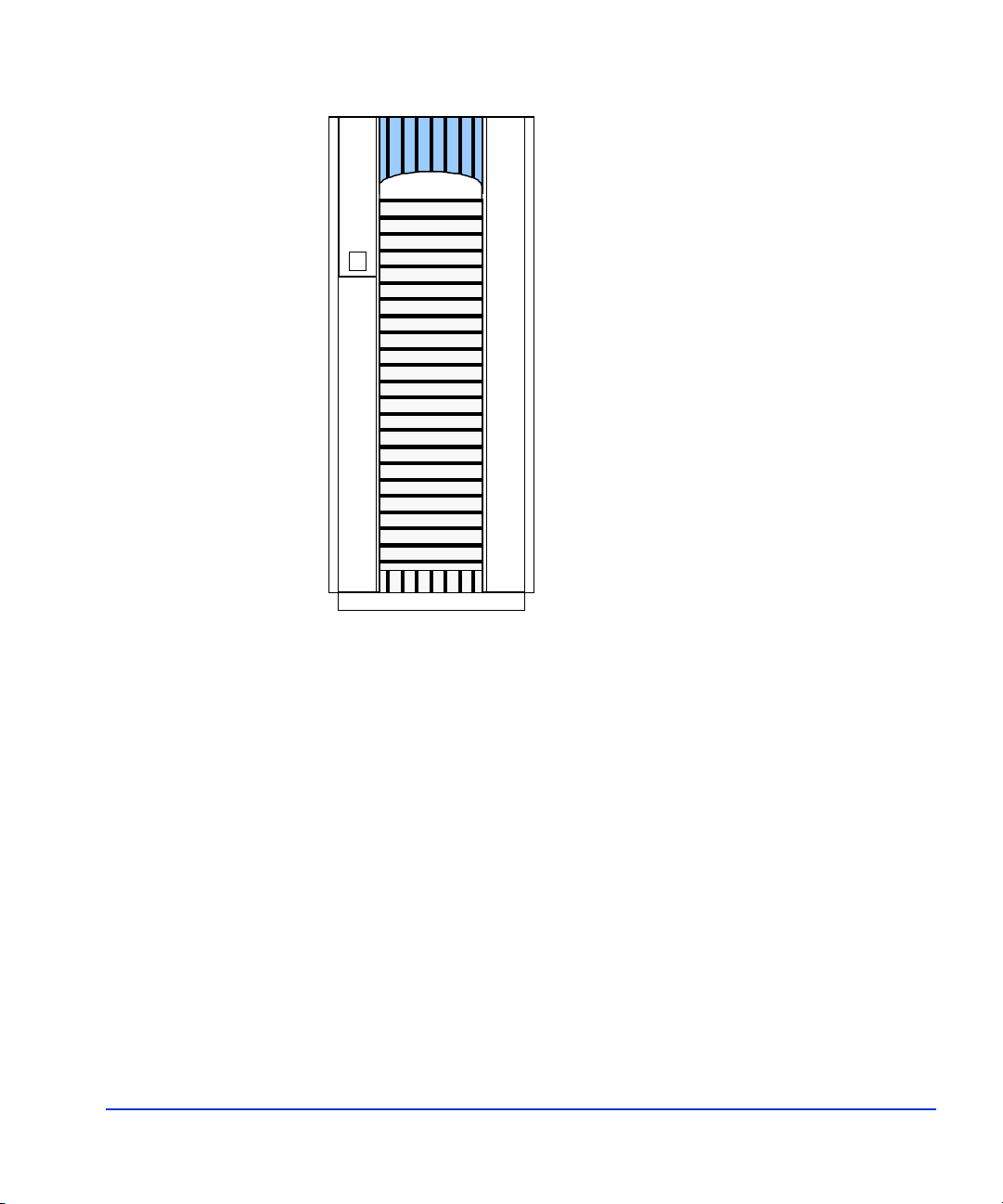
The HP Disk Array XP128
Your HP Disk Array XP128 is a high-performance disk array system. It is
used to store large quantities of data in an efficient and secure manner. All
components of the HP Disk Array XP128 are contained in a single cabinet,
providing a complete storage system with a small equipment footprint.
20 HP StorageWorks Disk Array XP128: Site Preparation Guide
Page 21
Preparing for installation 21
Page 22

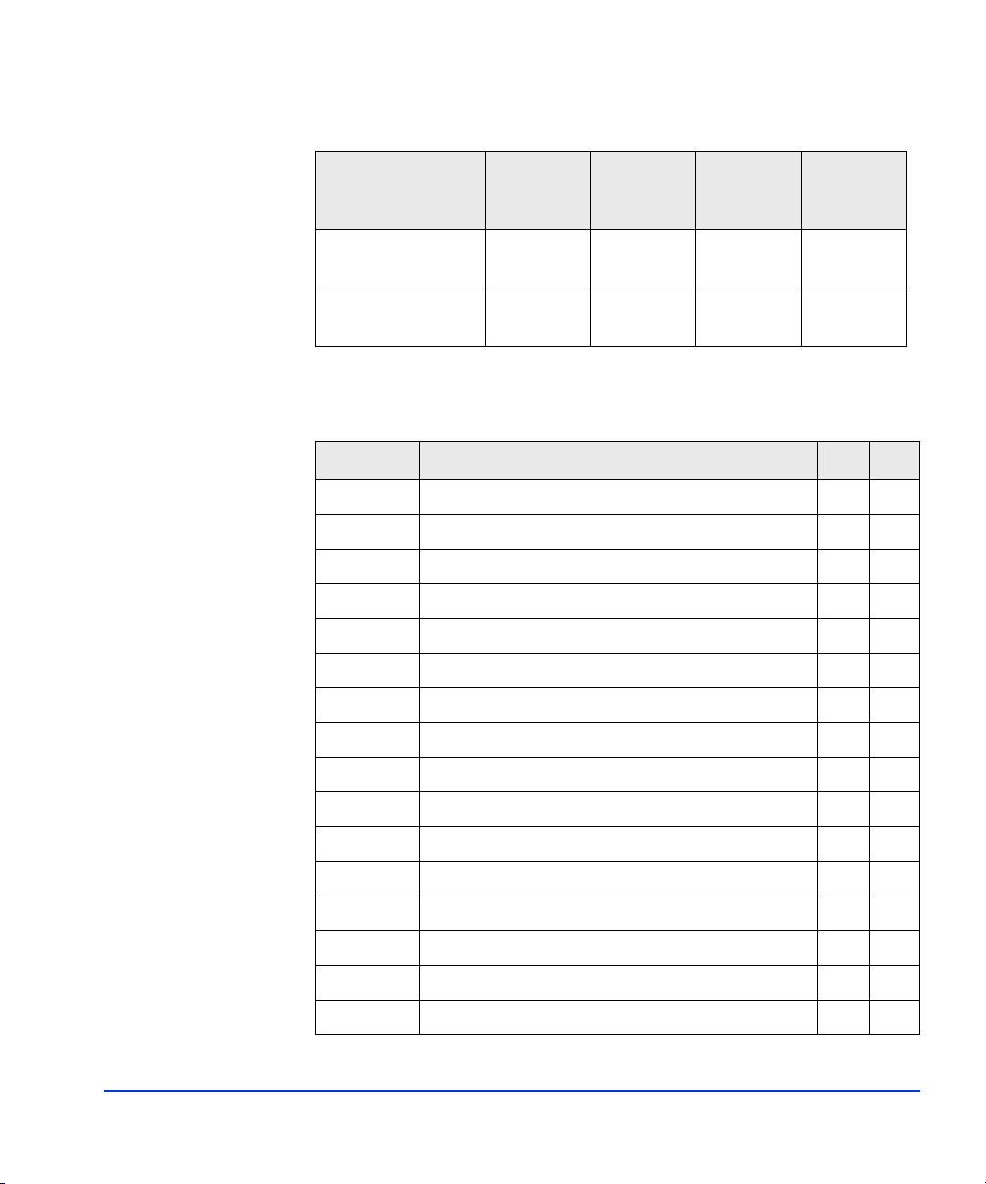
Physical requirements
Dimensions
An HP Disk Array XP128 consists of a single cabinet with the approximate
dimensions listed in the table below.
Minimum Dimensions mm in
Height 1860 73.6
Width 782 30.8
Depth 800 31.5
Weight
An HP Disk Array XP128 consists of a single cabinet. The table below
provides approximate weights for a minimum and maximum configuration.
The main factor that increases weight is the number of hard disk drives
(HDDs) in the disk array.
Weight kg lbs
Minimum
configuration
Maximum
configuration
655 1441
796 1751
Specific component dimensions and weights
The following two tables provide the physical dimensions and weights for
each HP Disk Array XP128 component. The values listed in these tables
are approximate and should be used for general reference only. Use these
values to estimate hallway and door clearances as well as floor strength for
moving the disk array.
22 HP StorageWorks Disk Array XP128: Site Preparation Guide
Page 23
Component Width Depth Height
Weight
Fully
Loaded
Disk array product
alone
Disk array
packaged*
782 mm
30.8 in
890 mm
35 in
800 mm
31.5 in
1000 mm
39.37 in
1860 mm
73.6 in.
2020 mm
79.58 in
796 kg
1751 lb
810 kg
1808 lb
* For shipment to locations outside the United States, Canada, and
Germany, add 88 kg (194 lbs) for an international shipping crate.
Product Description kg lb
A7890A Array Control Processor Pair - Std. Perf. 3.6 7.9
A7893A Additional Disk Port Switch Set 4.5 9.9
A7894A Disk Path Expansion Kit 2.0 4.4
A7900A 146 GB 10k rpm FC Array Group 4.0 8.8
A7900S 146 GB 10k rpm FC Spare Disk Drive 1.0 2.2
A7901A 73 GB 15k rpm FC Array Group 4.0 8.8
A7901S 73 GB 15k rpm FC Spare Disk Drive 1.0 2.2
A7903A 300 GB 10k rpm FC Array Group 4.0 8.8
A7903S 300 GB 10k rpm FC Spare Disk 1.0 2.2
A7907A SVP High Reliability Kit 14.5 31.9
A7909A 8-Port ExSA Channel Adapter Pair 4.2 9.2
A7909B 8-Port ExSA Channel Adapter Pair Enh. 4.2 9.2
A7910A 8-Port 1 Gbps FC/CA Adapter Pair 4.2 9.2
A7911A 4-Port 1-2 Gbps Autosensing FC/CA CHIP Pair 4.2 9.2
A7912A 8-Port 1-2 Gbps Autosensing FC/CA CHIP Pair 4.2 9.2
A7912B 8-Port 1-2 Gbps Enhanced FC CHIP Pair 4.2 9.2
Preparing for installation 23
Page 24

Product Description kg lb
A7913B 16-Port 1-2 Gbps Enhanced FC CHIP Pair 4.3 9.5
A7914A 8-Port 1 Gbps FICON - SW CHIP Pair 4.2 9.2
A7915A 8-Port 1 Gbps FICON - LW CHIP Pair 4.2 9.2
A7916B 8-Port 1-2 Gbps Enhanced FC - LW CHIP Pair 4.2 9.2
A7918A 2GB Cache Memory Module 0.2 0.4
A7921A 512 MB Shared Memory Module 0.05 0.1
A7922A Array Control Processor Pair - High Perf. 3.6 7.9
A7928A 36 GB 15k rpm FC array group - 4 disks 4.0 8.8
A7928S 36 GB 15k rpm FC spare disk drive 1.0 2.2
A7929A 73 GB 10k rpm FC array group - 4 disks 4.0 8.8
A7929S 73 GB 10k rpm FC spare disk drive 1.0 2.2
A7934A 4GB Cache Memory Module 0.2 0.4
A7935A 1 GB Shared Memory Module 0.05 0.1
A7938A 8-Port Gigabit Ethernet iSCSI - SW CHIP Pair 4.6 10.1
A7939A 4-Port Gigabit Ethernet NAS - SW CHIP Pair 4.5 9.9
24 HP StorageWorks Disk Array XP128: Site Preparation Guide
Page 25

Service and cable routing space requirements
This section contains information about space requirements and floor
loading for the HP Disk Array XP128.
Space planning
HP recommends that you prepare a revised floor plan showing the overall
location and arrangement of your computer room, including the addition of
your disk array. Enough room and lighting should be provided for people to
work effectively on a daily basis and for periodic servicing of equipment.
Be sure to consider interconnecting cables and power cord lengths when
planning your layout. Identify the location of all power outlets on the floor
plan. Plan to keep cables away from traffic areas to help prevent accidents
and equipment failures. Prior to installation, consult your site specialist
responsible for your computer room.
HP strongly discourages the use of carpeting, including antistatic varieties,
within 6.0 m (20 ft.) of the disk array. If this advice is not followed, you
should place static discharge mats where personnel must walk before
touching any part of the array. Failure to comply with this precaution can
result in equipment damage through static discharge.
If you are planning to construct a new computer room or modify an existing
site, first consult with your HP representatives and local contractors. It is
important to plan the site with future expansion in mind, so equipment can
be added without disturbing the computer operation.
Floor construction and loading
The computer room floor must be able to support the total weight of the
equipment as well as localized weight at each caster or foot of the
equipment cabinets. A common method of preparing an adequate floor for
a computer room is to construct a raised floor over the building floor. The
weight should be spread evenly and the flooring should provide an area
through which interconnecting cables can be run conveniently and
Preparing for installation 25
Page 26

unobtrusively. It should allow for optimum distribution of conditioned air.
Raised floor access ramps must not exceed 10
° slope.
To estimate floor strength, you should consider the following items:
• The total weight of the equipment (the unpacked and packaged
weights are listed in this chapter)
• The total weight of furniture such as desks, chairs, and storage
cabinets
• Total approximate weight of computer room personnel
• Weight of moving equipment such as forklifts, dollies, and so on.
Any questions regarding the adequacy of construction should be referred to
and evaluated by a qualified structural engineer.
Caution In addition to determining the adequacy of the computer site floor, ensure
that all floors, stairs, and elevators which might be used when the disk
array is moved to its destination can support the weight and size of the
equipment. Failure to comply can result in damage to the equipment or the
facility.
Maximum floor loading
Maximum point floor loading is 500 kg (1102.3 lbs). The table below
shows the floor load rating required for different service clearances
(minimum configuration).
Floor Load Rating
2
(kg/m
)
500 0.4 0.3 0.2 0.1 0
450 0.6 0.4 0.3 0.2 0.1
400 0.6 0.6 0.5 0.4 0.2
350 1.2 1.0 0.8 0.6 0.4
300 1.7 1.4 1.2 1.0 0.8
26 HP StorageWorks Disk Array XP128: Site Preparation Guide
Clearance (C) (m)
C=0 C=0.2 C=0.4 C=0.6 C=1.0
Page 27

The following figure shows the recommended XP128 service clearances.
Recommended dimension: 380 ( 200-380 ) *4
5464142.5
505
682
152.5
300 *3
a
*1
201 *5
307
199
105
426
150
95
76
100
16 750
109
d *2
782
168
G
G
582
648
Front
XP128
91
*1
b
201 *5
307
100
6767
16
230 *5
230 *5
(Unit:mm)
800
Recommended dimension:340 ( 200-340 ) *4
800 2400
800
C *1
G
Floor cutout area for cables
Screw jack
Caster
Service clearance
Grid panel (over 450mm x 450mm)
Opening on the bottom of the frame
(for external cable entry)
1. Clearance (a+b) depends on the floor load rating and clearance c.
2. Clearance (d) must be more than.0.28 m to allow for the DKC front door.
Preparing for installation 27
Page 28

3. The clearance on the front left side must be 280 mm or wider in order
to open the front door.
4. Dimensions in parentheses show the allowable rang e of floor cutout
sizes. The preferred position of the floor cutout is in the center of the
array. However, the position may be off-center as long as the cutout
allows smooth entrance of all external cables and is within the allowable
range.
5. This dimension varies depending on the floor cutout dimensions.
Minimum service clearances
The minimum service clearance is the smallest amount of additional floor
space surrounding the array required in order to access the disk array for
servicing. This space should be reserved for the disk array and never used
for storage.
The minimum service access is:
• Rear: 800 mm (31.5 in)
•Side: 0 mm
• Front: 800 mm (31.5 in)
28 HP StorageWorks Disk Array XP128: Site Preparation Guide
Page 29

Data comm requirements
Route data comm cables away from areas with high static electric fields
created by power transformers and heavy foot traffic. Use shielded data
comm cables that meet approved industrial standards to reduce the effects
of external fields.
Phone Home with Continuous Track
The HP Disk Array XP128 Phone Home capabilities detect and report
problems even before they are noticed by operators and users. Continuous
Track, a program that resides in the DKC, will phone “home” to the HP
Storage Technology Center (STC) and provides:
• Periodic “well” checkups
Every 24 hours, Continuous Track calls the HP Storage Technology
Center. When a successful connection is made, a preconfigured set of
files will be transferred from the DKC to the HP Storage Technology
Center. Your HP CE will set the time of call and set up the files to be
transferred. This checkup ensures the health of your disk array on a
daily basis.
• Incidental “sick” calls
When an error occurs, a service information message (SIM) is
generated. The SIM is stored in the DKC for use by your HP service
representative. The Continuous Track remote maintenance tool also
reports the SIMs to the STC. SIMs are classified according to severity,
and many SIMs do not require immediate attention. These SIMs are
often addressed during routine maintenance, and are corrected before a
failure occurs. Serious-level and acute-level SIMs are reported to the
STC immediately to ensure that the problem is addressed as soon as
possible.
To activate Phone Home, these requirements are necessary:
• Dedicated analog phone line
• An HP CE to configure Continuous Track
Preparing for installation 29
Page 30

HP StorageWorks Remote Web Console XP and Comand View XP AE
HP StorageWorks Remote Web Console (RWC) is a web-based software
application supplied with the XP128 disk array that permits you to connect
to, monitor, and manage the array. For managing multiple XP disk arrays,
you can upgrade to the optional Command View XP Advanced Edition
(CVXP AE) which also runs in a web browser. Using either or both
applications, you can remotely manage your HP Disk Array XP128 from
any location, enabling a remote expert to participate in problem
management. (If you already have an existing copy of Command View XP
(CV), you can also use that to manage XP128 disk arrays.)
RWC runs on the SVP inside the disk array and can be accessed from any
web browser on the LAN connected to the disk array. Command View and
Command V iew XP AE both run on an optional PC Device Manager server
that you must provide and install in your facility. You can use an existing
PC server if it meets the requirements specified for the software.
Local Area Network (LAN)
To connect to your intranet (public LAN), your CE will directly connect
your HP Disk Array XP128 to an available Ethernet port on your public
LAN. To ensure network security, consult with your HP CE and your
network administrator before selecting the location of your LAN drop .
Network hardware needed:
• One twisted pair (Cat 5) cable
• One available LAN drop on your intranet
Outside phone line
Recommendation Install a public voice phone line near your disk array. This phone line will
be used by you and your HP CE for voice communication in and outside of
your facility.
30 HP StorageWorks Disk Array XP128: Site Preparation Guide
Page 31

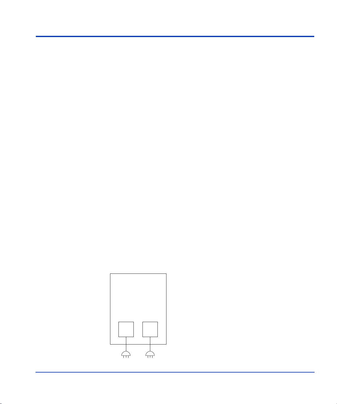
Electrical requirements
Power requirements are one of the most important considerations prior to
installing your disk array. For disk array cabinets with two connections to
AC power, if one input fails, the second input must be capable of
supporting the entire current demand nominally shared by the two power
connections. For disk array cabinets with four connections to AC power,
the two power connections to AC Box 1 or the two power connections to
AC Box 2 must be capable of supporting the entire current demand
nominally shared by the four power connections. The figure below shows
two examples of the fault-tolerant operation of the disk array.
Line voltage
Disk Array Cabinet
(2 AC Power
connections)
AC Power
Input Box
#1
The Disk Array can tolerate the loss
of connection to AC Box 1 or AC Box 2.
AC Power
Input Box
#2
Disk Array Cabinet
(4 AC Power
connections)
AC Power
Input Box
#1
The Disk Array can tolerate the loss
of connections to AC Box 1 or AC Box 2,
but no other combinations are allowed.
AC Power
Input Box
#2
The line voltage (AC) at the wall power outlet is a function of the local
power utility and your building power distribution network. Voltages
outside the operating range of the disk array can cause intermittent system
errors or a complete system shutdown. If required, the HP CE, along with
Preparing for installation 31
Page 32

your electrician, can determine the line voltage and make
recommendations. Avoid the use of a line voltage conditioner.
Make sure that the selected power distribution unit (if one is used) supports
the correct voltage to support your entire system.
Branch circuit breakers
See “Branch circuit requirements” (page 42) for the specific branch circuit
requirements for your power situation.
Three-phase branch circuit breakers
The power cords supplied with each HP Disk Array XP128 configured for
three-phase power are sized for connection to a 30-amp circuit.
Single-phase branch circuit breakers
The power cords supplied with each HP Disk Array XP128 configured for
single-phase power are sized for connection to a 30 or 50-amp circuit.
30-amp, single-phase power is available by special order only.
Frequency
AC line frequency is normally determined by your local power providers.
In some cases, electrical power is supplied by motor-generators. Shifts in
AC line frequency can cause system errors. Your HP CE can monitor the
frequency of the input AC line power and make recommendations, if
necessary.
AC line voltage requirements
The AC power requirements for your HP Disk Array XP128 listed are for
each power cord. Each array frame has two or four power cords. In case of
a failure of the power source for one cord, the power requirements and
hence the current requirement for the remaining power cord will
approximately double.
32 HP StorageWorks Disk Array XP128: Site Preparation Guide
Page 33

The table below lists the basic AC power requirements for a 50-amp,
single-phase XP128.
Nominal Rated Voltage (VAC)
Parameter
200 208*220 230 240
Minimum operating voltage (VAC) 184 191 202 212 221
Maximum operating voltage (VAC) 212 220 233 244 254
Rated line current per power cord
16.2 15.1 14.9 14.3 13.8
(amps RMS)
Number of power cords 2 2 2 2 2
Recommended circuit breakers (amps) 50 50 50 50 50
Number of circuit breakers 2 2 2 2 2
Dropout carry-through time at
30 30 30 30 30
minimum line voltage (ms)
* 60 Hz only.
The table below lists the basic AC power requirements for a 30-amp,
single-phase XP128.
Nominal Rated Voltage (VAC)
Parameter
200 208*220 230 240
Minimum operating voltage (VAC) 184 191 202 212 2 21
Maximum operating voltage (VAC) 212 220 233 244 254
Rated line current per power cord
10.2 9.5 9.4 9.0 8.7
(amps RMS)
Number of power cords 4 4 4 4 4
Recommended circuit breakers (amps) 30 30 30 30 30
Number of circuit breakers 4 4 4 4 4
Dropout carry-through time at
30 30 30 30 30
minimum line voltage (ms)
* 60 Hz only.
Preparing for installation 33
Page 34

The table below lists the basic AC power requirements for a 30-amp,
three-phase, XP128 (50 or 60Hz).
Nominal Rated Voltage (VAC)
Parameter
Minimum operating voltage
(VAC)
Maximum operating voltage
(VAC)
Rated line current
per power cord (amps RMS)
Number of power cords 2 2 2 2 2 2 2 2
Recommended circuit
breakers (amps)
Number of circuit breakers 2 2 2 2 2 2 2 2
Dropout carry-through time
at minimum line voltage
(ms)
* 60 Hz only.
Safety and dedicated earth ground
200 208*220 230 240 380 400 415
184 191 202 212 221 350 368 382
212 220 233 244 254 403 424 440
11.1 10.7 10.0 9.6 9.1 6.0 5.5 5.3
30 30 30 30 30 30 30 30
30 30 30 30 30 30 30 30
The primary reason for earth grounding electrical systems is safety. The
safety ground is required by the National Electric Code (USA) and most
other local, regional, and national codes. In addition to safety ground, HP
requires that a dedicated (earth reference) ground be installed as a common
reference point for all system components. You should consult with your
HP CE and your electrician to ensure that your electrical system meets all
local and national safety codes.
34 HP StorageWorks Disk Array XP128: Site Preparation Guide
Page 35

Grounding requirements
Your disk array must meet all of the following conditions:
• An insulated grounding conductor that is identical in size, insulation
material, and thickness to the ungrounded branch-circuit supply
conductors. It should be green, with or without yellow stripes, and is to
be installed as a part of the branch circuit that supplies the unit or
system. This means the ground conductor must be run in the same
conduit, armored cable, or other cable bundle as the phase wires.
• Grounding as prescribed by your local country codes.
• The grounding conductor mentioned above should be grounded to
earth at the service equipment or other acceptable building earth
ground such as the building frames (in the case of a high rise steel
frame structure).
• IT configured grounding systems are not certified for use with the
XP128 as these grounding systems may not have solidly
conductor-connected grounded power systems and/or they may have
resistive impedance inserted in ground and/or neutral lines. The
XP128 requires a solidly conductor-connected ground and may
require a separate neutral in the case of WYE or STAR connections.
Receptacles
When receptacles are used to connect your disk array to AC power, they
must include a dedicated ground connection that is insulated from the
receptacle. It is important that the receptacle box be grounded with an
additional ground connection that is separate from the dedicated ground.
The additional ground can be hard conduit.
Each disk array cabinet has two or four separate connections to AC power.
For disk array cabinets with two connections to AC power, each input must
be capable of supporting the entire current demand for the cabinet. For disk
array cabinets with four connections to AC power, the two inputs to AC
Box 1 or the two inputs to AC Box 2 must be capable of supporting the
entire current demand for the cabinet. The figure below shows two
examples of the fault-tolerant operation of the disk array.
Preparing for installation 35
Page 36

Disk Array Cabinet
Disk Array Cabinet
(2 AC Power
connections)
AC Power
Input Box
#1
The Disk Array can tolerate the loss
of connection to AC Box 1 or AC Box 2.
AC Power
Input Box
#2
(4 AC Power
connections)
AC Power
Input Box
#1
The Disk Array can tolerate the loss
of connections to AC Box 1 or AC Box 2,
but no other combinations are allowed.
AC Power
Input Box
#2
Specific power plugs and receptacles are required for the XP128,
depending on the power option you specify when ordering the HP Disk
Array XP128. The power cords on 60 Hz cabinets are shipped with plugs
attached. The power cords on 50 Hz cabinets are shipped without plugs.
Customers are responsible for having the correct plugs and receptacles
installed by an electrician in compliance with local electrical requirements
and practices.
Caution When installing the receptacles, the electrician must ensure that each
receptacle has its own neutral (if required) and ground. Using the same
neutral/ground for more than one circuit causes voltage loss and heat
problems. It can create a fire hazard. A shared neutral conductor that fails
open-circuit can cause overvoltage damage to equipment.
36 HP StorageWorks Disk Array XP128: Site Preparation Guide
Page 37

The table below lists the plug and connector part numbers for 60 Hz
configurations of the HP Disk Array XP128.
Breaker
Power Source Frequency
Rating
Plug Connector
Single-phase 60 Hz 30 A Russellstoll
3750DP
Russellstoll 3933
(Alt. 9C33U0)
or 3753
(Alt. 9R33U0W)
50 A Russellstoll
9P53U2
Russellstoll
9C53U2
or 9R53U2W
Three-phase 60 Hz 30 A Russellstoll
3760PDG
Russellstoll 3934
(Alt. 9C34U0)
or 3754
(Alt. 9R34U0W)
The Russellstoll connectors are available through most industrial electrical
distributors. HP has arranged for these connectors to also be available in
stock from the distributors listed below. These distributors are able to ship
worldwide and ship via customer preference.
Beck Electrical Supply
2775 Goodrick Avenue
Richmond, CA 94801 USA
Telephone: (800) 466-4395
Fax: (800) 466-5442
Contact: Ken Mogan
casales@beckelectric.com
Source Research, Inc. (SRI)
2160 Sunnydale Boulevard
Clearwater, FL 33765-2108 USA
Telephone: (800) 356-0259
Contact: Erik Peterson, telephone extension 302
http://www.sourceresearch.com/index.cfm
Preparing for installation 37
Page 38

Power line transients
Heavy electrical loads from nearby machinery or equipment (elevators,
electric welders, etc.) can cause intermittent system problems with
sophisticated electronic equipment, even if that equipment is on a separate
circuit breaker. When faced with these conditions, you should provide a
separate, completely independent power panel with an isolated ground and
circuit breaker coming directly from the main building power source or
secondary power source.
If necessary, your HP CE can measure your power line noise level and
make recommendations concerning the use of line treatment devices.
Maximum peak inrush and crest factor
The maximum peak inrush currents for the HP Disk Array XP128 are listed
in the table below.
Power Single-Phase Three-Phase
30-amp 86 A for 10ms N/A
50-amp 135 A for 10ms 135 A for 10ms
The crest factors for the HP Disk Array XP128 are listed in the table below.
Single-Phase Three-Phase
2.27 1.94
38 HP StorageWorks Disk Array XP128: Site Preparation Guide
Page 39

Sources of electrical interference
Ensure that the disk array is protected from sources of electrical
interference:
wall outlets Convenience power outlets for building maintenance
equipment (vacuum cleaners, floor buffers, etc.) must
be wired from circuit breakers on a power panel
separate from the computer system panel. The ground
wires from these outlets must be connected to the
normal building distribution panel and not to the
system ground.
If a separate power source and separate ground are not
provided, operation of janitorial equipment can induce
electrical noise and cause abnormal operation of the
computer system. Your electrician can verify whether
or not maintenance outlets are on separate panels.
lightning In some geographical areas it may by advisable to
install lightning protection for both personnel and
computer systems.
The principles of lightning protection and personnel
safety are outlined in detail in the lightning protection
code contained in the National Fire Protection
Association (NFPA) Handbook.
vibration Continuous vibration can cause a slow degradation of
mechanical parts and, when severe, can cause data
errors in disk drives. Mechanical connections such as
printed circuit assembly (PCA) conductors, cable
connectors, and processor backplane wiring can also
be affected by vibrations.
electromagnetic
interference
Preparing for installation 39
The disk array is specifically designed to reduce its
susceptibility to radiated and conducted interference.
Electromagnetic interference can cause a variety of
system problems. Your HP CE can advise you about
many of the most common causes of electromagnetic
interference.
Page 40

metal If metal is used in the construction of the raised floor,
ensure that there is a common ground connection
between the raised floor and main floor to avoid
possible build up of different voltage potentials.
Failure to comply can result in serious injury to
personnel and damage to equipment.
flammable
materials
airborne
contaminants
Fundamental safeguards for disk arrays should include
a site well away from any sources of potential damage.
The system should not be installed or operated in an
environment where there is a risk of fire or explosion
due to the presence of highly flammable gases, volatile
liquids, or combustible dust.
Airborne contaminants and particles of a certain size
and hardness can damage your disk arrays . Some of
the most common contaminants are dust, smoke, ash,
eraser debris, food crumbs, and salty air.
Your HP CE can assist you in determining whether or
not you need be concerned about airborne
contaminants.
Also, see “Dust and pollution control” (page 53) and
“Metallic particulate contamination” (page 53).
40 HP StorageWorks Disk Array XP128: Site Preparation Guide
Page 41
Three-phase AC cabling for USA
Each three-phase HP Disk Array XP128 has two main disconnect devices
(two main breakers for dual power lines) so that AC power to the unit can
be supplied from separate power distribution panels with two po wer-sup ply
cords.
Trained service personnel should be present whenever the disk array is
being connected to a new power source for the first time.
Connecting the external power supply cord
Three-phase HP Disk Array XP128s are factory-configured for 30-amp
power.
30-amp, three-phase power
When the disk array uses 30-amp, three-phase input power, HP Disk Array
XP128s have two power cords as shown in the figure below. If one power
source malfunctions, the other power source assumes the total load,
providing uninterrupted operation. HP recommends that each power cord
have a separate electrical circuit as its source in case of a circuit failure.
Each power-supply cord is supplied with an attachment plug type
Russellstoll 3760PDG. Be sure to install Russellstoll 3934 (alternate,
9C34U0) or 3754 (alternate, 39R34U0W) socket receptacles between the
power distribution panel of the building and the attachment plugs for the
XP128.
Disk Array Cabinet
AC Power
Input Box
#1
Preparing for installation 41
AC Power
Input Box
#2
30 A30 A
Page 42

The power cords provided with your 30-amp, three-phase disk array are
non-shielded, type ST or equivalent, with four #8 AWG (minimum)
conductors terminated at one end with an assembled plug connector.
Branch circuit requirements
To protect your disk array, your building must be wired correctly. Each
supply (“hot”) conductor must be protected by a short-circuit protective
device and by an overcurrent protective device. The current specifications
for the overcurrent protective devices required for three-phase operation are
listed in the table on page 34.
All protective devices must comply with national standards of the country
where the units are to be installed. If a protective device interrupts any
supply conductor, it must also interrupt all other supply conductors.
Overcurrent protection is not required for the neutral conductor of this unit.
Only 50 Hz, three-phase configurations have a neutral conductor.
42 HP StorageWorks Disk Array XP128: Site Preparation Guide
Page 43

Three-phase AC cabling for Europe
Each three-phase HP Disk Array XP128 has two main disconnect devices
(two main breakers for dual power lines) so that AC power to the unit can
be supplied from separate power distribution panels with two po wer-sup ply
cords.
Trained service personnel should be present whenever the disk array is
being connected to a new power source for the first time.
Connecting the power supply cords
All 50 Hz, European HP Disk Array XP128 cabinets are shipped with
unterminated power cords. Your electrician must select and install the
correct power plug. Power cords of type H07RN-F or equivalent, with five
2
6 mm
Caution Be sure to connect the power cords to the distribution panel as shown in the
figure below. Improper wiring of the neutral conductor may cause damage
to your disk array. To reduce the risk of a wrong connection, you should
use a plug and socket that is approved for this disk array. It is your
electrician’s r esponsibili ty to select and install the proper plug.
conductors per cord, are provided with the unit.
XP128
Power Cord
Black
Brown
Black
Blue
Green/Yellow
L1
L2
L3
N
G
Line
Line
Line
Neutral
Safety Ground
To Po wer
Distribution
Panel
When connecting to 380 to 415-volt service, a WYE configuration with
neutral and ground conductors (in addition to the three-phase wires — a
total of five wires) is required.
High leakage current can occur between the power supply and the unit. To
avoid electrical shock, ensure that the protective earth connection is made
before the supply connections.
Preparing for installation 43
Page 44

Branch circuit requirements
When the supplied line to line voltage is in the 380 to 415-volt range, the
connection must be a five-wire WYE or STAR connection.
To protect your disk array, your building must be wired correctly. Each
supply (“hot”) conductor should be protected by a short-circuit protective
device and by an overcurrent protective device. The current specifications
for the overcurrent protective devices required for three-phase operation are
listed in the table on page 34.
The protective device must comply with national standards of the country
where the units are to be installed. If a protective device interrupts a supply
conductor, it must also interrupt all other supply conductors.
Overcurrent protection is not required for the neutral conductor.
44 HP StorageWorks Disk Array XP128: Site Preparation Guide
Page 45

Single-phase AC cabling for USA
When configured for 50-amp, single-phase power, the HP Disk Array
XP128 cabinet has two power cords and two main disconnect devices so
that AC power can be supplied from separate power distribution panels.
When configured for 30-amp, single-phase power, each HP Disk Array
XP128 cabinet has four power cords and four main disconnect devices.
Caution Trained service personnel should be present whenever the disk array is
being connected to a new power source for the first time.
Connecting the power supply cords
The HP Disk Array XP128 can be factory-configured for 50-amp or
30-amp, single-phase power.
50-amp, single-phase power
The 50-amp HP Disk Array XP128 cabinet has two power-supply cords
with attachment plug type Russellstoll 9P53U2 as shown in the figure
below. Be sure to install Russellstoll 9C53U2 or Russellstoll 9R53U2W
socket receptacles between the power distribution panel of the building and
the attachment plugs for the unit.
Disk Array Cabinet
AC Power
Input Box
#1
AC Power
Input Box
#2
50 A50 A
Preparing for installation 45
Page 46

The power cords provided with your disk array are non-shielded, type ST
or equivalent with three #6 AWG (minimum) conductors terminated at one
end with an assembled 9P53U2 plug connector.
30-amp, single-phase power
The 30-amp HP Disk Array XP128 cabinet has four power-supply cords
with attachment plug type Russellstoll 3750DP as shown in the figure
below. Be sure to install Russellstoll 9C33U0 or 9R33U0W socket
receptacles between the building’s power distribution panel and the
attachment plugs for each unit.
Disk Array Cabinet
AC Power
Input Box
#1
AC Power
Input Box
#2
30 A30 A 30 A30 A
The power cords that are provided with your disk array are nonshielded,
type SJT or equivalent with three #10 AWG (minimum) conductors that are
terminated at one end with an assembled plug connector.
46 HP StorageWorks Disk Array XP128: Site Preparation Guide
Page 47

Branch circuit requirements
To protect your disk array, your building must be wired correctly. Each
supply (“hot”) conductor must be protected by a short-circuit protective
device and by an overcurrent protective device. The current specifications
for the overcurrent protective devices required for single-phase operation
are listed in the table on page 33.
The protective device must comply with national standards of the country
where the units is to be installed (USA). If a protective device interrupts a
supply conductor, it must also interrupt all other supply conductors.
Note In many cases, local codes do not allow a branch circuit fitted with a
50-amp receptacle or connector to be protected by an overcurrent
protection device with a rating lower than 50 amps. You can order your HP
Disk Array XP128 with the 30-amp power option to comply with these
local codes. Your electrician knows the appropriate code requirements for
your location/site.
Preparing for installation 47
Page 48

Single-phase cabling for Europe
When configured for 50-amp, single-phase power, the HP Disk Array
XP128 cabinet has two power cords and two main disconnect devices so
that AC power can be supplied from separate power distribution panels.
When configured for 30-amp, single-phase power, the HP Disk Array
XP128 cabinet has four power cords and four main disconnect devices.
Caution Trained service personnel should be present whenever the disk array is
being connected to a new power source for the first time.
Connecting the power supply cord
50-amp power cords
The 50-amp HP Disk Array XP128 cabinet has two power-supply cords.
The power cords included with the unit are type H07RN-F or equivalent
2
with three 10 mm
Caution Be sure to connect the power cords to the distribution panel as shown in the
figure below. Improper wiring of the neutral conductor may cause damage
to your disk array. To reduce the risk of a wrong connection, you should
use a plug and socket that is approved for this disk array. It is your
electrician’s r esponsibili ty to select and install the proper plug.
conductors.
XP128
Power Cord
Black
Blue
Green/Yellow
L1
N
G
Line
Neutral
Safety Ground
To Po wer
Distribution
Panel
30-amp power cords
The 30-amp HP Disk Array XP128 cabinet has four power-supply cords.
The power cords included with the unit are type H07RN-F or equivalent
2
with three 6 mm
48 HP StorageWorks Disk Array XP128: Site Preparation Guide
conductors.
Page 49

High leakage current may occur between the power supply and the unit. T o
avoid an electrical shock, be sure the protective earth connection is made
before the supply connections.
Branch circuit requirements
To protect your disk array, your building must be wired correctly. Each
supply (“hot”) conductor must be protected by a short-circuit protective
device and by an overcurrent protective device. The current specifications
for the overcurrent protective devices required for single-phase operation
are listed in the tables on page 33.
The protective device must comply with national standards of the country
where the units is to be installed. If a protective device interrupts a supply
conductor, it must also interrupt all other supply conductors.
Note In many cases, local codes do not allow a branch circuit fitted with a
50-amp receptacle or connector to be protected by an overcurrent
protection device with a rating lower than 50 amps. You can order your HP
Disk Array XP128 with the 30-amp power option to comply with these
local codes. Your electrician knows the appropriate code requirements for
your location/site.
Preparing for installation 49
Page 50

Uninterruptible Power Supply (UPS)
Caution This uninterruptible power supply (UPS) reference is for a product UPS
implementation. If you are planning or already have a sitewide UPS,
Hewlett-Packard recommends against a product UPS powered by a
sitewide UPS for the XP128.
Most HP Disk Array XP128 units are installed in data centers where an
uninterruptible power supply (UPS) strategy is already in place. However,
if you are making your first large disk array pu rchase, you may hav e a need
for a separate UPS solution. HP references the Silcon DP300 series UPS
solution. The Silcon DP300 is a product from American Power Conversion
Corp (APC), manufacturers of uninterruptible power systems.
UPS features
The APC UPS, Silcon DP300 series, provides the following feature set:
• Protection against short line transients
• Continued availability during short duration power failures (a
minimum of 30 minutes for a fully-configured system)
• Stable AC output voltage
• LCD display unit with ability to display key AC input/output
parameters, alarm log, events log and programming functions
• Communications interface option for communicating a remote UPS
shutdown through the serial port connection.
UPS limitations
While the UPS will provide uninterrupted power to the XP array in the
event of a power failure, once the battery runtime is exceeded, it will shut
down, resulting in a loss of AC power to the array. The UPS does have the
ability to communicate an oncoming shutdown to the host via the Silcon
50 HP StorageWorks Disk Array XP128: Site Preparation Guide
Page 51

Triple Chassis. The host can then pass this message in-band to the XP array
using the “xppf” program.
Power requirements: single secondary input (primary offline)
The values in the table below are based on a worst-case voltage (rated
voltage –10%) and a maximum configuration for disk array contro l and
disk frames. A phase imbalance of 15% is also included in the calculation.
Input (Vac) Power Required
208 25.0 A (9.0kVA)
400 16.3 A (11.3k VA)
Reference supplier information
American Power Conversion
32 Fairgrounds Road
West Kingston, RI 0289
Phone Numbers:
Technical Support & Product Info.
1-800-800-4272
Corporate
1-800-788-2208
1-401-789-5735
To find out more about the recommended American Power Conversion
UPS, travel to the APC web site:
www.apcc.com
You can also contact your HP service representatives for specific
configuration needs for your area.
Preparing for installation 51
Page 52

Environmental requirements
The environmental specifications for operating your disk array must be
satisfied prior to installation.
Air conditioning ducts
Use separate computer room air conditioning duct work. If it is not separate
from the rest of the building, it might be difficult to control cooling and air
pressure levels. Duct work seals are important for maintaining a balanced
air conditioning system and high static air pressure. Adequate cooling
capacity means little if the direction humidity levels increase when the
ducts are exposed to warm air.
Humidity
Maintain proper humidity levels. High humidity levels causes galvanic
actions to occur between some dissimilar metals. This eventually causes a
high resistance between connections, leading to equipment failure.
Caution Low humidity tends to increase electrostatic discharge (ESD) voltage
potential. ESD can cause component damage during servicing operations.
Static charges (voltage levels) occur when objects are separated or rubbed
together. The voltage level of a static charge is determined by the following
factors:
• Types of materials
• Relative humidity
• Rate of change or separation
52 HP StorageWorks Disk Array XP128: Site Preparation Guide
Page 53

Follow these precautions to minimize possible ESD-induced failures in
your computer room:
• Install conductive flooring (conductive adhesive must be used when
laying tiles).
• Use conductive wax if waxed floors are installed.
• Ensure that both equipment and flooring are properly grounded an d
are at the same ground potential.
• Use conductive tables and chairs.
• Store spare electric parts in antistatic containers.
• Maintain recommended humidity level and airflow rates.
Low humidity levels are often the result of the facility heating system and
occur during the cold season. Most heating systems provide air with a low
humidity level, unless the system has a built-in humidifier.
Dust and pollution control
For trouble free operation, disk drives require a dust-free environment, The
HP Disk Array XP128 disk drives are protected from dust particles by
mechanical air filters designed to trap large dust particles. Smaller particles
can pass through some filters, and, over a period of time, can cause
problems in mechanical parts. Small dust particles can be prevented from
entering the computer room by maintaining its air conditioning system at a
high static air pressure level.
Metallic particulate contamination
Metallic particulates can be especially harmful around electronic
equipment. This type of contamination may enter the data center
environment from a variety of source, including but not limited to raised
floor tiles, worn air conditioning parts, heating ducts, rotor brushes in
vacuum cleaners, or printer component wear. Because metallic particulates
conduct electricity, they have an increased potential for creating short
circuits in electronic equipment.This problem is aggravated by the
increasingly dense circuitry of electronic equipment.
Preparing for installation 53
Page 54

Over time, very fine whiskers of pure metal can form on electroplated zinc,
cadmium, or tin surfaces. If these whiskers are disturbed, they may break
off and become airborne, possibly causing failures or operational
interruptions. For over 50 years, the electronics industry has been aware of
the relatively rare but possible threat posed by metallic particulate
contamination. During recent years, a growing concern has developed in
computer rooms where these conductive contaminants are formed on the
bottom of some raised floor tiles.
Although this problem is relatively rare, it may be an issue in your
computer room. Since metallic contamination can cause permanent or
intermittent failures on your electronic equipment, Hewlett-Packard
strongly recommends that your site be evaluated for metallic particulate
contamination before the installation of electronic equipment.
Temperature and humidity specifications
When the disk array is operating, the recommended temperatu re ran ge is
21°C to 24°C and recommended relative humidity range is (at 22
between 40 to 55 percent. The following table lists the full range of
temperature, humidity, and vibration specifications for the HP Disk Array
XP128. The vibration and shock specifications apply to all three axes.
°C)
Caution No condensation in or around the HP Disk Array XP128 should be
observed under any conditions.
54 HP StorageWorks Disk Array XP128: Site Preparation Guide
Page 55

Shipping and
Specification Operating
1
Nonoperating
2
Storage
3
Temperature (°C) 16 to 32 –10 to +43 –25 to +60
4
Relative humidity (%)
20-80 8-90 5-95
Max wet bulb (°C) 26 27 29
Temperature deviation
10 10 20
(°C/hour)
Vibration
5
0.25mm,
5-10Hz
0.05G,
10-300Hz
2.5mm,
5-10 Hz
0.5G,
10-70 Hz
0.05mm,
70-99 Hz
1.0G,
99-300 Hz
Shock 8G, 15ms
1. Environmental specification for operating condition should be satisfied before the disk
subsystem is powered on. Maximum temperature of 32ºC should be strictly satisfied at
the air inlet portion. The recommended temperature range is 21~24ºC.
2. Nonoperating condition includes both packing and unpacking conditions unless
otherwise specified.
3. On shipping/storage condition, the product should be packed with factory packing.
4. No condensation in and around the drive should be observed under any conditions.
5. The specifications apply to all three axes.
6. See ASTM D999-86, Standard Methods for Vibration Testing of Shipping Containers.
7. See ASTM D880-86, Standard Methods of Incline Impact Test for Shipping Containers.
8. See ASTM D775-80, Standard Methods for Drop Test for Loaded Boxes.
0.5, 15 min.
6
at four most severe
resonance between
5-200Hz
Horizontal:
7
incline impact:
1.22m/s
Vertical:
8
rotational edge:
0.15m
Preparing for installation 55
Page 56

Heat dissipation
The table below lists the heat dissipation specifications of the HP Disk
Array XP128 in a maximum configuration.
Power consumption (kVA) 5.42
Heat dissipation (kW) 5.03
BTUs per hour 17,164
kcal per hour 4,326
56 HP StorageWorks Disk Array XP128: Site Preparation Guide
Page 57

Altitude
When operating the HP Disk Array XP128, the maximum altitu de is 3,000
meters. For nonoperational situations, the maximum altitude is 4,000
meters.
Preparing for installation 57
Page 58

Acoustics
Computer equipment and air conditioning blowers cause computer rooms
to be noisy. Ambient noise level in a computer room can be reduced as
follows:
dropped ceiling Cover with a commercial-grade fire-resistant,
acoustic rated, fiberglass ceiling tile.
sound deadening Cover the walls with sound-deadening material.
removable partitions To be most effective, use foam rubber models.
The acoustic emission specifications for the HP XP128 Disk Array are:
• 7.63 Bels (A) sound power
• 59.8 dB (A) sound pressure, operator position
58 HP StorageWorks Disk Array XP128: Site Preparation Guide
Page 59

Delivery space requirements
There should be enough clearance to move equipment safely from the
receiving area to the computer room. Permanent obstructions, such as
pillars or narrow doorways, can cause equipment damage.
Delivery plans should include the possible removal of walls or doors. The
physical dimensions are summarized on page 22.
Preparing for installation 59
Page 60

60 HP StorageWorks Disk Array XP128: Site Preparation Guide
Page 61

4
Receiving your HP Disk Array XP128
Your HP Disk Array XP128 is shipped directly from HP. If your disk array
is part of a system order, HP coordinates the shipment of equipment from
all locations so that it arrives at your site at approximately the same time.
In some cases, factors beyond the control of HP can cause delivery delays.
If you have not received your equipment within a two-week period, notify
your HP sales representative. The HP sales representative will trace your
order and expedite delivery.
Caution Be sure to allow for size and weight in regard to placing the disk array at
its installation site. Refer to
weight values.
“Dimensions” (page 22) for specific size and
Receiving your HP Disk Array XP128 61
Page 62

Checking for shipping shortage and damage
As your disk array arrives, check the carrier’s bill of lading carefully to
ensure that all items shipped by HP are delivered. Notify the carrier
immediately if there are any discrepancies or items missing.
Inspect all of the shipping containers for signs of damage before actually
unpacking the equipment. Some typical signs of shipping damage are dents,
scratches, cuts, or water marks. If any damage is found, note on the bill of
lading that there is apparent damage subject to inspection. Arrange for the
carrier’s representative and a representative from Hewlett-Packard to be
present when the item in question is unpacked.
Regardless of the circumstances, the HP CE will take immediate action to
replace any damaged components without waiting for the settlement of
claims.
62 HP StorageWorks Disk Array XP128: Site Preparation Guide
Page 63

Unpacking the cartons
The equipment cartons can be unpacked at your convenience; it is your
responsibility to have the equipment unpacked and moved to its proper
installation location prior to the day of installation.
The disk array frame is very heavy. In a maximum configuration, it weighs
more than 1700 pounds. It is recommended that three (3) people unpack
and move this equipment to avoid injury.
Retain the packing list (invoice) for each carton that is to be unpacked and
ensure that each item on the list can be accounted for. Contact your HP
sales representative immediately if there are any missing items, or if the
items are not the same as you ordered.
Leave the sealed cartons or packages of CDs, cables, and any other
installation hardware intact for the HP CE. Your HP CE and HP ASE will
install and configure the disk array.
Receiving your HP Disk Array XP128 63
Page 64

64 HP StorageWorks Disk Array XP128: Site Preparation Guide
Page 65

Glossary
ACP Array control processor. The ACP handles the passing of data between the
cache and the physical drives held in the DKU. ACPs work in pairs,
providing a total of eight SCSI buses. Each SCSI bus associated with one
ACP is paired with a SCSI bus on the other ACP pair element. In the event
of an ACP failure, the redundant ACP takes control. Both ACPs work
together sharing the load.
AL Arbitrated loop.
AL-PA Arbitrated loop physical address.
allocation The ratio of allocated storage capacity versus total capacity as a percentage.
“Allocated storage” refers to those LDEVs that have paths assigned to
them. The allocated storage capacity is the sum of the storage of these
LDEVs. Total capacity refers to the sum of the capacity of all LDEVs on
the disk array.
array group A group of 4 or 8 physical hard disk drives (HDDs) installed in an XP disk
array and assigned a common RAID level. RAID1 array groups are made
up of 4 HDDs (2D+2D). A RAID1 group is two 4 HDD array groups
concatenated together (4D+4D). RAID5 array groups are made up of 4 or 8
HDDs, depending on whether they are RAID5 3D+1P or RAID5 7D+1P,
respectively. All RAID6 array groups are made up of 8 HDDs (6D+2P).
ASE Application System Engineer.
BC The HP StorageW orks Business Copy XP software program, which enables
you to maintain up to nine internal copies of logical volumes on the disk
array.
Glossary 65
Page 66

C-Track The HP StorageWorks Continuous Track XP software program, which
detects internal hardware component problems on a disk array and
automatically reports them to the HP STC.
CA The HP S torageWorks Continuous Access XP program, which enables you
to replicate data stored on a local disk array to a remote disk array.
cache Very high speed memory that is used to speed I/O transaction time. All
reads and writes to the XP array family are sent to the cache. The data is
buffered there until the transfer to/from physical disks (with slower data
throughput) is complete.
The benefit of cache memory is that it speeds I/O throughput to the
application. The larger the cache size, the greater the amount of data
buffering that can occur and the greater throughput to the applications.
XP arrays support a range of cache memory. In the event of power loss,
battery power holds up the contents of cache for up to 36 hours.
CE Customer engineer.
channel adapter
(CHA)
The channel adapter (CHA) provides the interface between the disk array
and the external host system. Occasionally this term is used synonymously
with the term channel host interface processor (CHIP).
channel host
Synonymous with the term channel adapter (CHA).
interface processor
(CHIP)
channel processor
(CHP)
The processors located on the channel adapter (CHA). Synonymous with
CHIP.
command device A volume on the disk array that accepts Continuous Access or Business
Copy control operations which are then executed by the disk array.
control unit To organize the storage space attached to the DKC, you can group similarly
configured logical devices (LDEVs) with unique control unit images
(CUs). CUs are numbered sequentially. The disk array supports a certain
number of CUs, depending on the disk array model. Each CU can manage
multiple LDEVs. Therefore, to uniquely identify a particular LDEV
requires both the CU number and the LDEV number.
66 HP StorageWorks Disk Array XP128: Site Preparation Guide
Page 67

CU Control unit.
CVS Custom volume size. CVS devices (OPEN-x CVS) are custom volumes
configured using array management software to be smaller than normal
fixed-size OPEN system volumes. Synonymous with volume size
customization (VSC).
disk adapter (DKA) Synonymous with the term ACP.
disk unit (DKU) The array hardware that houses the disk array physical disks.
disk controller
(DKC)
disk recovery and
restore unit (DRR)
The array hardware that houses the channel adapters and service processor
(SVP).
The unit responsible for data recovery and restoration in the event of a
cache failure.
disk group The physical disk locations associated with a parity group.
disk type The manufacturing label burned into the physical disk co ntro ller firmware.
In most cases, the disk type is identical to the disk model number.
emulation modes The logical devices (LDEVs) associated with each RAID group are
assigned an emulation mode that makes them operate like OPEN system
disk drives. The emulation mode determines the size of an LDEV.
OPEN-3: 2.46 GB
OPEN-8: 7.38 GB
OPEN-9: 7.42 GB
OPEN-E: 13.56 GB
OPEN-K: Not available on XP128 arrays
OPEN-L: 36 GB
OPEN-M: Not available on XP128 arrays
OPEN-V: User-defined custom size
EPO Emergency power-off.
ESCON Enterprise System Connection (the IBM trademark for optical channels).
expanded LUN A LUN is normally associated with only a single LDEV. The LUSE feature
allows a LUN to be associated with 1 to 36 LDEVs. Essentially, LUSE
makes it possible for applications to access a single large pool of storage.
Glossary 67
Page 68

The LUSE feature is available when the HP StorageWorks LUN
Configuration Manager product is installed.
ExSA Extended serial adapter.
failover Disconnecting a failed unit or path and replacing it with an alternative unit
or path in order to continue functioning.
FC Fibre Channel.
FC-AL Fibre Channel arbitrated loop.
FCP Fibre Channel Protocol.
fence level A level for selecting rejection of a write I/O request from the host according
to the condition of mirroring consistency.
FICON IBM mainframe Fiber Optic Connection.
GB Gigabytes.
GLM Gigabyte link module.
HA High availability.
HBA Host bus adapter. A built-in function or a card installed in a PC or other
host computer to enable connection of the host to the SAN.
host mode Each port can be configured for a particular host type. These modes are
represented as two-digit hexadecimal numbers. For example, host mode 08
represents an HP-UX host.
hot standby Using two or more servers as a standby in case of a primary server failure.
HP Hewlett-Packard Development Company.
I/O Input/output (applies to an operation or device).
LAN Local area network.
LD, LDEV Logical device. An LDEV is created when a RAID group is carved into
pieces according to the selected host emulation mode (that is, OPEN-3,
OPEN-8, OPEN-9). The number of resulting LDEVs depends on the
selected emulation mode. The term LDEV is often used synonymously
with the term volume.
68 HP StorageWorks Disk Array XP128: Site Preparation Guide
Page 69

LED Light emitting diode.
local disk A disk in the host.
LU Logical unit.
LUN Logical unit number. A LUN results from mapping a SCSI logical unit
number, port ID, and LDEV ID to a RAID group. The size of the LUN is
determined by the emulation mode of the LDEV, and the number of
LDEVs associated with the LUN. For example, a LUN associated with two
OPEN-3 LDEVs has a size of 4,693 MB.
LUSE Logical unit size expansion. See also Expanded LUN.
m Meters.
MB Megabytes.
MCU Main control unit.
MIX A circuit board in the disk control unit that includes disk adapters and
channel adapters for interfacing disk drives and the host to cache memory.
mirroring
The consistency (usability) of data in a volume (for example, S-VOL).
consistency
mm Millimeters.
MR Magnetoresistive.
ms, msec Milliseconds.
mutual hot standby
Two servers that are poised to cover for each other if necessary.
system
NAS Network attached storage.
node Logically speaking, an environment where instances can be executed.
Physically, a processor, which is an element of a cluster system.
NVS Nonvolatile storage.
OFC Open Fibre Control.
OLM Optical link module.
Glossary 69
Page 70

OS Operating system.
PA Physical address.
parity group A parity group is a disk configuration in which multiple disks work
together to provide redundancy. Synonymous with “array group.”
partition Dividing a specific physical disk into two or more areas as if there are two
or more physical disks.
path Paths are created by associating a port, a target, and a LUN ID with one or
more LDEVs.
PCI Power control interface or peripheral component interconnect.
port A physical connection that allows data to pass between a host and the disk
array. The number of po rts on an XP disk array depends on the number of
supported I/O slots and the number of ports available per I/O adapter. The
XP family of disk arrays supports Fibre Channel (FC) ports as well as other
port types. Ports are named by port group and port letter, such as CL1-A.
CL1 is the group, and A is the port letter.
P-P Point-to-point.
PS Power supply.
RS Russellstoll®, a brand of electrical plugs and receptacles manufactured by
Thomas & Betts Corporation.
RAID Redundant array of independent disks.
RAID group See “array group.”
RAID level A RAID Level is one of the ways that disk drives are grouped together to
improve performance, data availability/reliability or both. RAID levels are
defined from RAID0 to RAID6. HP StorageWorks Disk Arrays in the XP
product family support RAID1, RAID5 and RAID6. Not all of these RAID
levels are supported by all XP family members. Consult the owner's guide
or your HP representative for the details of which RAID levels are
supported by your specific XP disk array.
RAM Random access memory.
70 HP StorageWorks Disk Array XP128: Site Preparation Guide
Page 71

RM HP StorageWorks RAID Manager XP, a command line interface for
managing XP arrays.
R-SIM Remote service information message.
R/W, r/w Read/write.
script file A file containing a shell script.
SCSI Small computer system interface.
shell script A command sequence executed by a UNIX shell.
sidefile An area of cache used to store the data sequence number, record location,
record length, and queued control information.
SIM Servic e information message.
SMI-S Storage Management Initiative Specification.
SMS System managed storage.
SNMP Simple Network Management Protocol.
SSID Storage subsystem identification.
STC HP Storage Technology Center.
SVP Service processor, which is the PC built into the disk controller. The SVP
provides a direct interface into the disk array. SVP use is reserved for HP
support representatives only.
TB Terabyte.
TCP/IP Transmission control protocol/Internet protocol
TID Target ID.
VSC Volume size customization. Synonymous with CVS.
VOLID Volume ID.
volume Synonymous with LDEV.
Glossary 71
Page 72

72 HP StorageWorks Disk Array XP128: Site Preparation Guide
Page 73

Index
A
AC
connectors
power
receptacles
acoustics
air conditioning
air ducts
altitude
37
32
35
58
15
52
57
American Power Conversion (APC)
supplier information
51
application software engineer (ASE)
site preparation team
authorized resellers
12
6
B
branch circuit
Europe
Europe, single-phase
USA
USA, single-phase
breakers, circuit
building access & security
44
49
42
47
32
15
C
cables
data comm
routing space
clearances
Command View
29
25
28
30
Command View XP Advanced Edition
computer room
requirements
19
connectors
AC
37
suppliers
conventions, document
51
7
current
AC
32
peak inrush, crest
38
customer
site preparation responsibilities
12
customer engineer (CE)
site preparation team
12
D
damage, shipping
62
data communications
requirements
delivery space
dimensions
29
59
22
30
Index 73
Page 74

disk arrays
dimensions
managing
supported
weight
22
30
5
22
documentation
conventions
related
53
dust
7
5
E
earth
34, 35
electrical
15
interference
sources of 39
requirements 31
environmental requirements
error messages
29
F
floor
loading
frequency, AC
25, 26
32
G
ground
34, 35
H
heat dissipation
56
help
obtaining
8
HP
service organization
humidity
52, 54
11
L
line voltage
31
19, 52
P
phone home
phone line
physical requirements
power
AC
requirements
29
29
22
41
32
31
power cord
3-phase AC (Europe)
3-phase AC (USA)
41
single-phase (Europe)
single-phase AC (USA)
power supply
50
R
receptacles, AC
35
related documentation
list of
5
Remote W eb Console
resellers, authorized
30
6
S
safety
18
sales representative (SR)
site preparation team
service
clearances
sick calls
SIMs
29
25, 28
29
single-phase power
Europe
USA
48
45
site preparation
physical requirements
preparations before delivery
team
12
43
48
45
12
22
16
74 HP StorageWorks Disk Array XP128: Site Preparation Guide
Page 75

space
delivery
59
specifications
temperature, humidity
static electricity
52
suppliers, power connectors
54
51
T
technical support
temperature
6
54
three-phase power
Europe
USA
43
41
timetable
planning
transients, power
16
38
U
uninterruptible power supply (UPS)
unpacking
63
V
voltage
AC
32
line
31
50
W
web site
HP storage
HP support
5
6
weight
components
disk array
well checkups
Index 75
23
22
29
Page 76

76 HP StorageWorks Disk Array XP128: Site Preparation Guide
 Loading...