

Page 1

HPE XP Storage Adapter for
Microsoft® Volume ShadowCopy
Service User’s Guide
HPE XP P9500 Storage, HPE XP7 Storage
Abstract
This document provides details on the Volume Shadow Copy Service (VSS), which allows you to conduct a hot backup of data
(snapshots) without stopping online applications.
Part Number: Z7550-01742R
Published: January 2016
Edition: 2
Page 2

© Copyright 2015, 2016 Hewlett Packard Enterprise Development LP
The information contained herein is subject to change without notice. The only warranties for Hewlett Packard Enterprise products and services
are set forth in the express warranty statements accompanying such products and services. Nothing herein should be construed as constituting
an additional warranty. Hewlett Packard Enterprise shall not be liable for technical or editorial errors or omissions contained herein.
Confidential computer software. Valid license from Hewlett Packard Enterprise required for possession, use, or copying. Consistent with FAR
12.211 and 12.212, Commercial Computer Software, Computer Software Documentation, and Technical Data for Commercial Items are licensed
to the U.S. Government under vendor's standard commercial license.
Links to third-party websites take you outside the Hewlett Packard Enterprise website. Hewlett Packard Enterprise has no control over and is not
responsible for information outside the Hewlett Packard Enterprise website.
Acknowledgments
Intel®, Itanium®, Pentium®, Intel Inside®, and the Intel Inside logo are trademarks or registered trademarks of Intel Corporation or its subsidiaries
in the United States and other countries.
Microsoft® and Windows® are either registered trademarks or trademarks of Microsoft Corporation in the United States and/or other countries.
Adobe® and Acrobat® are trademarks of Adobe Systems Incorporated.
Java and Oracle are registered trademarks of Oracle and/or its affiliates.
UNIX® is a registered trademark of The Open Group.
Revision History
September 2015Revision 1
First Edition
December 2015Revision 2
Rebranding Changes
Page 3

Contents
1 Volume Shadow Copy Service..........................................................................10
Overview.............................................................................................................................................10
Overview of the VSS Provider............................................................................................................10
2 Environmental Prerequisites..............................................................................12
System configuration..........................................................................................................................12
Examples of supported system configurations..............................................................................12
Example of VMware Guest to Guest Backup (FC) function system configuration........................13
Examples of Ext Stor configuration...............................................................................................17
Example of HA configuration.........................................................................................................18
Server prerequisites............................................................................................................................19
Software prerequisites........................................................................................................................21
Operating systems.........................................................................................................................21
Virtual environments......................................................................................................................21
Software........................................................................................................................................22
Services.........................................................................................................................................22
The software required to use the VMware Guest to Guest Backup (FC) function........................22
Support scope of Ext Stor configuration .......................................................................................22
RSG..........................................................................................................................................22
RSG assignment of each resource..........................................................................................23
Placement location of command device which is connected to host.......................................24
Support scope of HA configuration................................................................................................24
Adapter function.......................................................................................................................24
Placement location of command device which is connected to host.......................................25
Storage requirements.........................................................................................................................25
Restrictions and points of consideration.............................................................................................26
Restrictions and points of consideration related to the environmental configuration....................26
Server Account Authentication.................................................................................................26
Environmental configuration via remote desktop.....................................................................26
Items to confirm during installation...........................................................................................27
Installation drive.......................................................................................................................27
Path length of the installation folder.........................................................................................27
Number of LUs which can be mapped to the host group.........................................................27
How to create setup, maintenance configuration, and configuration files................................27
Hewlett Packard Enterprise shortcut of the Start Menu...........................................................27
Installation of other VSS Provider............................................................................................28
Account Authentication............................................................................................................28
RAID Manager (HORCM)........................................................................................................28
Host group creation..................................................................................................................28
Creating a user authentication account for storage administration..........................................28
Assigning LDEV ID...................................................................................................................29
Resource Group (Resource Partition)......................................................................................29
Raw Device Mapping (RDM)....................................................................................................29
Command device.....................................................................................................................29
SCSI controller type.................................................................................................................29
SCSI controller created by VSS Provider.................................................................................29
VMware HA..............................................................................................................................29
Operational restrictions and points of consideration.....................................................................30
Multiple instances of the VSS Provider....................................................................................30
Unregistering a disk array system............................................................................................30
Number of user accounts that can be registered for a disk array system................................30
Changing the configuration file or the maintenance configuration file.....................................30
Contents 3
Page 4

Restarting a server during a backup........................................................................................30
Log collection during problem occurrence...............................................................................30
Parallel backup of multiple data on the same volume..............................................................30
Event logs which the VSS service outputs...............................................................................31
Event log which does not affect the VSS Provider operation...................................................31
The operative restrictions of the concurrence configuration change for the equivalence disk
array system.............................................................................................................................32
A volume status at the time of ResyncLuns abnormal finish....................................................32
Specifying WWN of the import server from the configuration file.............................................32
The number of the target backup volume................................................................................33
Owner node of virtual machine on shared volume...................................................................33
Backup from multiple servers and virtual machines at the same time.....................................33
RAID level................................................................................................................................33
Emulation type..........................................................................................................................33
Confirming the resource lock...................................................................................................34
Restrictions on using together with RAID Manager.................................................................34
LUSE Volume...........................................................................................................................34
Operation when Online Migration is running............................................................................34
Multiple generation management by enabling Snapshot resync mode...................................34
External Storage (Ext Stor)......................................................................................................34
Server to be registered using the Register Server function.....................................................34
Account authorization of vCenter Server.................................................................................34
Unregistering the registered vCenter Server account..............................................................35
Deleting S-VOL/V-VOL from the GUI tool................................................................................35
Instance number of RAID Manager..........................................................................................35
Operational restriction on the simultaneous configuration change for the same virtual
machine....................................................................................................................................35
3 Configuration Procedure....................................................................................36
Installation...........................................................................................................................................36
User edit files......................................................................................................................................37
Setup files......................................................................................................................................38
Maintenance configuration files.....................................................................................................42
Preparing configuration files and restarting RAID Manager (HORCM).........................................43
Preparing a disk array system............................................................................................................45
4 Uninstallation Procedure...................................................................................49
5 (Missing number)...............................................................................................51
6 Repair Installation..............................................................................................52
7 Using the VSS Provider GUI.............................................................................53
Functions of GUI tool..........................................................................................................................53
Starting the GUI tool......................................................................................................................54
Add Storage...................................................................................................................................55
Refresh..........................................................................................................................................56
Business Copy...............................................................................................................................56
Displaying S-VOL pair status...................................................................................................56
Creating an S-VOL...................................................................................................................56
Deleting an S-VOL...................................................................................................................57
Resynchronization (Resync) of BC pair...................................................................................57
Split of BC pair.........................................................................................................................58
Snapshot.......................................................................................................................................58
Display Snapshot pair..............................................................................................................58
Deleting a V-VOL.....................................................................................................................58
Options..........................................................................................................................................59
4 Contents
Page 5

Snapshot data pool property list...............................................................................................59
VSS Provider behavior.............................................................................................................59
Register Server..............................................................................................................................59
Repair installation when starting the GUI Tool..............................................................................60
8 Troubleshooting.................................................................................................61
Message IDs.......................................................................................................................................62
Message classifications.................................................................................................................62
Viewing messages.........................................................................................................................62
Log files..............................................................................................................................................63
Log file type...................................................................................................................................64
Generation management of log files.............................................................................................65
Log file generation management specifications.......................................................................66
Error messages..................................................................................................................................67
Error messages output by the installer..........................................................................................67
E2008001.................................................................................................................................67
E2008002.................................................................................................................................68
E2008003.................................................................................................................................68
E2008004.................................................................................................................................68
E2008005.................................................................................................................................68
W2008011................................................................................................................................69
E2008012.................................................................................................................................69
E2008013.................................................................................................................................69
E2008014.................................................................................................................................69
Standard InstallShield messages..................................................................................................69
Error messages output in event logs.............................................................................................75
5001.........................................................................................................................................75
5004.........................................................................................................................................75
5006.........................................................................................................................................75
5008.........................................................................................................................................76
5010.........................................................................................................................................76
5012.........................................................................................................................................76
5014.........................................................................................................................................77
5017.........................................................................................................................................77
5019.........................................................................................................................................77
5021.........................................................................................................................................78
5022.........................................................................................................................................78
5023.........................................................................................................................................79
5025.........................................................................................................................................79
5028.........................................................................................................................................80
5030.........................................................................................................................................80
5032.........................................................................................................................................80
5033.........................................................................................................................................81
5034.........................................................................................................................................81
Error messages output by the GUI tool, and VSS Provider..........................................................82
E1000007.................................................................................................................................82
E1000008.................................................................................................................................82
E100000D................................................................................................................................82
E100000F.................................................................................................................................82
E1000011.................................................................................................................................83
E1000030.................................................................................................................................83
E1000037.................................................................................................................................83
E100003B.................................................................................................................................83
E1000056.................................................................................................................................84
E1000058.................................................................................................................................84
Contents 5
Page 6

E100005A.................................................................................................................................85
E100005D................................................................................................................................85
E100005F.................................................................................................................................85
E1000063.................................................................................................................................86
E1000064.................................................................................................................................86
E100006C................................................................................................................................86
E100006D................................................................................................................................87
E100008A.................................................................................................................................87
E1000090.................................................................................................................................87
E1000091.................................................................................................................................87
E100009B.................................................................................................................................88
E100009F.................................................................................................................................88
E10000C7................................................................................................................................88
E10000C9................................................................................................................................88
E10000CB................................................................................................................................89
E10000CD................................................................................................................................89
E10000D0................................................................................................................................89
E10000D1................................................................................................................................89
E10000D3................................................................................................................................90
E10000D4................................................................................................................................90
E10000D7................................................................................................................................90
E10000D9................................................................................................................................91
E10000DB................................................................................................................................92
E10000DD................................................................................................................................92
E10000DE................................................................................................................................93
E10000DF................................................................................................................................93
E10000F1.................................................................................................................................94
E10000F3.................................................................................................................................94
E10000F4.................................................................................................................................94
E10000F5.................................................................................................................................94
E10000F7.................................................................................................................................95
E10000F8.................................................................................................................................95
E10000FB................................................................................................................................95
E10000FD................................................................................................................................96
E10000FE................................................................................................................................96
E1000105.................................................................................................................................96
E100010A.................................................................................................................................96
E100010B.................................................................................................................................97
E100010E.................................................................................................................................97
E100010F.................................................................................................................................97
E1000110.................................................................................................................................98
E1000111.................................................................................................................................98
E1000118.................................................................................................................................98
E1000119.................................................................................................................................98
E1000126.................................................................................................................................99
E1000138.................................................................................................................................99
E1000139.................................................................................................................................99
E100013A...............................................................................................................................100
E1000145...............................................................................................................................100
E1000149...............................................................................................................................100
E100014C..............................................................................................................................101
E100014F...............................................................................................................................101
E1000151...............................................................................................................................102
E100015C..............................................................................................................................102
E100015D..............................................................................................................................102
6 Contents
Page 7

E2002003...............................................................................................................................102
E2002004...............................................................................................................................102
E2002005...............................................................................................................................103
E2002006...............................................................................................................................103
E2002008...............................................................................................................................103
E2002009...............................................................................................................................104
E200200A...............................................................................................................................104
E200200B...............................................................................................................................104
E200200D..............................................................................................................................104
E200200E...............................................................................................................................104
E2002010...............................................................................................................................105
E2002011...............................................................................................................................105
E2002012...............................................................................................................................105
E2002013...............................................................................................................................105
E2002014...............................................................................................................................106
E2002015...............................................................................................................................106
E2002017...............................................................................................................................106
E2002018...............................................................................................................................106
E2002019...............................................................................................................................107
E200201A...............................................................................................................................107
E200201B...............................................................................................................................107
E200201C..............................................................................................................................108
E200201D..............................................................................................................................108
E200201E...............................................................................................................................108
E200201F...............................................................................................................................109
E2002020...............................................................................................................................109
E2002021...............................................................................................................................109
E2002022...............................................................................................................................110
E2002023...............................................................................................................................110
E2002024...............................................................................................................................111
E2002025...............................................................................................................................111
E2002026...............................................................................................................................111
E2002028...............................................................................................................................112
E200202A...............................................................................................................................112
E200202B...............................................................................................................................112
E200202E...............................................................................................................................113
E200202F...............................................................................................................................113
E2002030...............................................................................................................................113
E2002032...............................................................................................................................113
E200203B...............................................................................................................................113
E200203D..............................................................................................................................114
E200203E...............................................................................................................................114
E200203F...............................................................................................................................114
E2002040...............................................................................................................................114
E2002041...............................................................................................................................115
E2002042...............................................................................................................................115
E2002043...............................................................................................................................115
E2002044...............................................................................................................................115
E2002045...............................................................................................................................116
E2002046...............................................................................................................................116
E2002048...............................................................................................................................116
E2002049...............................................................................................................................116
E200204A...............................................................................................................................117
E200204B...............................................................................................................................117
E200204C..............................................................................................................................117
Contents 7
Page 8

E200204E...............................................................................................................................117
E200204F...............................................................................................................................118
E2002050...............................................................................................................................118
E2002052...............................................................................................................................118
E2002053...............................................................................................................................118
E2002056...............................................................................................................................119
E2002057...............................................................................................................................119
E2002058...............................................................................................................................120
E200205A...............................................................................................................................120
E200205C..............................................................................................................................120
E200205F...............................................................................................................................121
E2002060...............................................................................................................................122
E2002064...............................................................................................................................122
E2002065...............................................................................................................................122
E2002066...............................................................................................................................122
E20020B8...............................................................................................................................123
E20020B9...............................................................................................................................123
E20020C0..............................................................................................................................123
E20020CF..............................................................................................................................124
E20020D1..............................................................................................................................124
E20020D2..............................................................................................................................124
E20020D3..............................................................................................................................124
E20020D4..............................................................................................................................125
E20020D5..............................................................................................................................125
E20020D6..............................................................................................................................126
E20020DB..............................................................................................................................126
E20020DC..............................................................................................................................126
E20020DD..............................................................................................................................127
E20020DE..............................................................................................................................127
E20020DF..............................................................................................................................127
E20020E1...............................................................................................................................127
E20020E2...............................................................................................................................128
E20020E3...............................................................................................................................128
E20020E5...............................................................................................................................129
E20020E6...............................................................................................................................129
E20020EA..............................................................................................................................130
E20020EB..............................................................................................................................130
E20020ED..............................................................................................................................130
E20020EE..............................................................................................................................131
E20020EF..............................................................................................................................131
E20020F0...............................................................................................................................131
E20020F1...............................................................................................................................132
E20020F2...............................................................................................................................132
E20020F3...............................................................................................................................132
E20020F4...............................................................................................................................133
I1000031................................................................................................................................133
About errors attributable to storage environment.............................................................................133
About errors attributable to disk array systems...........................................................................133
An error attributable to vSphere environment.............................................................................134
Confirmation and support after a recovery.......................................................................................135
Pair status of P-VOL, S-VOL.......................................................................................................135
Whether S-VOL is mapped to a backup server...........................................................................136
Whether V-VOL is created by VSS Provider...............................................................................136
An online status of the P-VOL.....................................................................................................136
Resource lock status...................................................................................................................136
8 Contents
Page 9

Existence or non-existence of RDM setting and VMDK file........................................................136
Information collected during problem occurrence.............................................................................137
Windows event logs.....................................................................................................................137
VSS Provider-related logs...........................................................................................................137
Configuration and Maintenance configuration file.......................................................................137
Version.txt file..............................................................................................................................137
Version of VSS Provider..............................................................................................................137
VSS trace....................................................................................................................................138
Version of vSphere Client............................................................................................................138
9 Configuration method when VSS Provider is used in virtual DKC..................139
Physical DKC....................................................................................................................................140
GUI..............................................................................................................................................140
Configuration file..........................................................................................................................141
Virtual DKC.......................................................................................................................................141
GUI..............................................................................................................................................141
Configuration file..........................................................................................................................141
10 Support and other resources.........................................................................142
Accessing Hewlett Packard Enterprise Support...............................................................................142
Accessing updates............................................................................................................................142
Websites...........................................................................................................................................142
Customer self repair.........................................................................................................................143
Remote support................................................................................................................................143
Documentation feedback..................................................................................................................143
A Warranty and regulatory information...............................................................144
Warranty information.........................................................................................................................144
Regulatory information......................................................................................................................144
Belarus Kazakhstan Russia marking...........................................................................................144
Turkey RoHS material content declaration..................................................................................145
Ukraine RoHS material content declaration................................................................................145
Glossary.............................................................................................................146
Index...................................................................................................................148
Contents 9
Page 10
1 Volume Shadow Copy Service
Overview
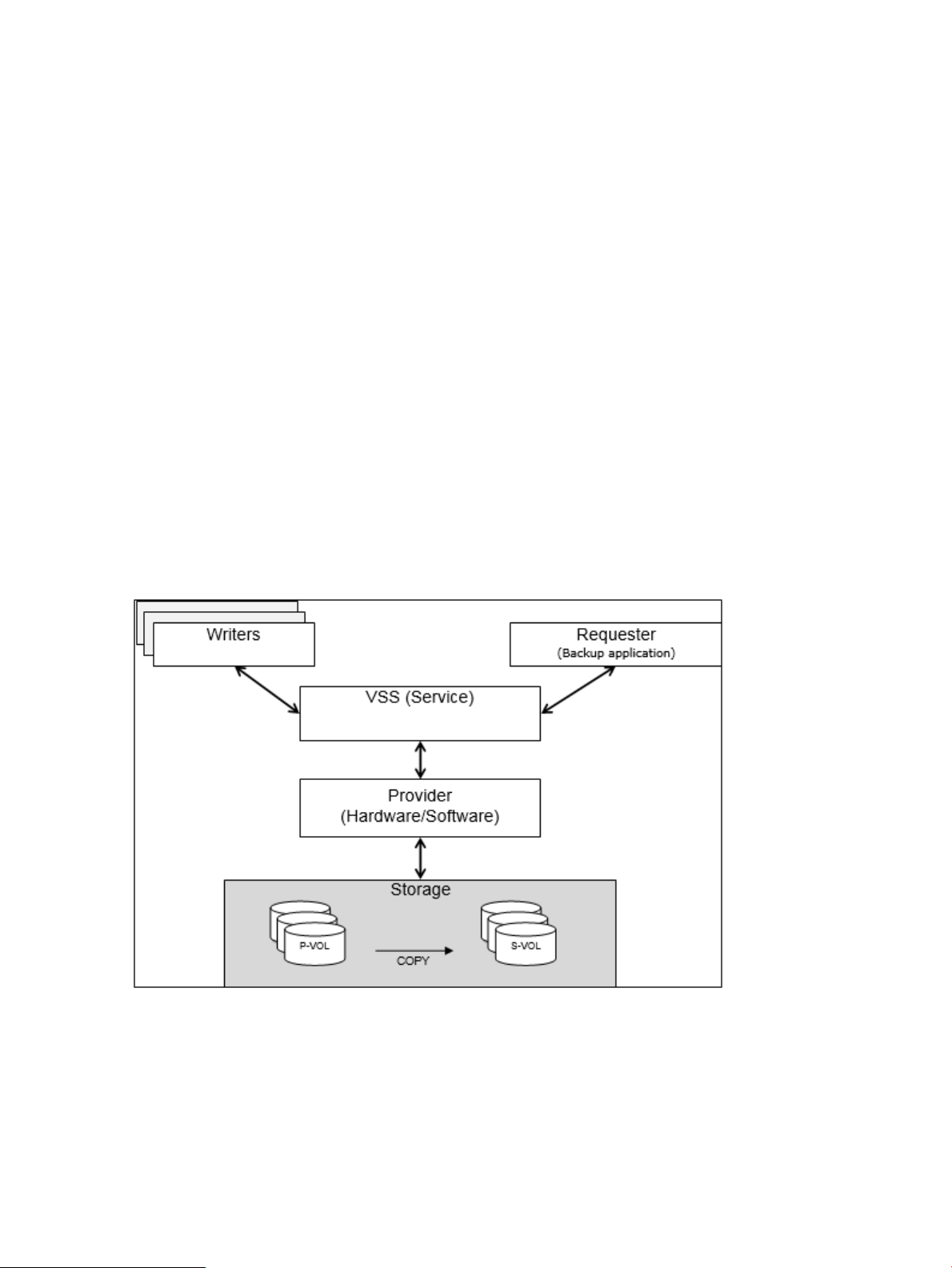
The Volume Shadow Copy Service (VSS) provides a backup function that generates consistent
point-in-time copies of data known as snapshots.
VSS lets you conduct a hot backup of data without stopping online applications by linking
applications, backup software, and disk array systems that are supported by VSS.
VSS consists of the following components:
• Provider — The provider actually creates snapshots. The provider consists of a software
component that comes with the OS and a hardware component which may be acquired from
some source such as a disk array vender. The VSS provider described in this manual is the
hardware component.
• Writers — The writer quiesces the OS or an application and will flush data as needed in
order to create a consistent state. Only operating systems and applications that include a
VSS writer can work with VSS.
• Requester — This component requests creation, operation, or deletion of snapshots. Usually
backup and recovery software like Microsoft’s Data Protection Manager, or HPE Data
Protection Suite can operate as a VSS requester.
• VSS — This service in the Windows operating system operates as a coordinator for the
provider, the writers, and the requester.
Figure 1 Concept of VSS.png
Overview of the VSS Provider
The VSS Provider is a program that controls a data backup function and works with the Microsoft
Volume Shadow Copy Service (VSS). It uses Business Copy, Snapshot or Fast Snap in Hewlett
10 Volume Shadow Copy Service
Page 11
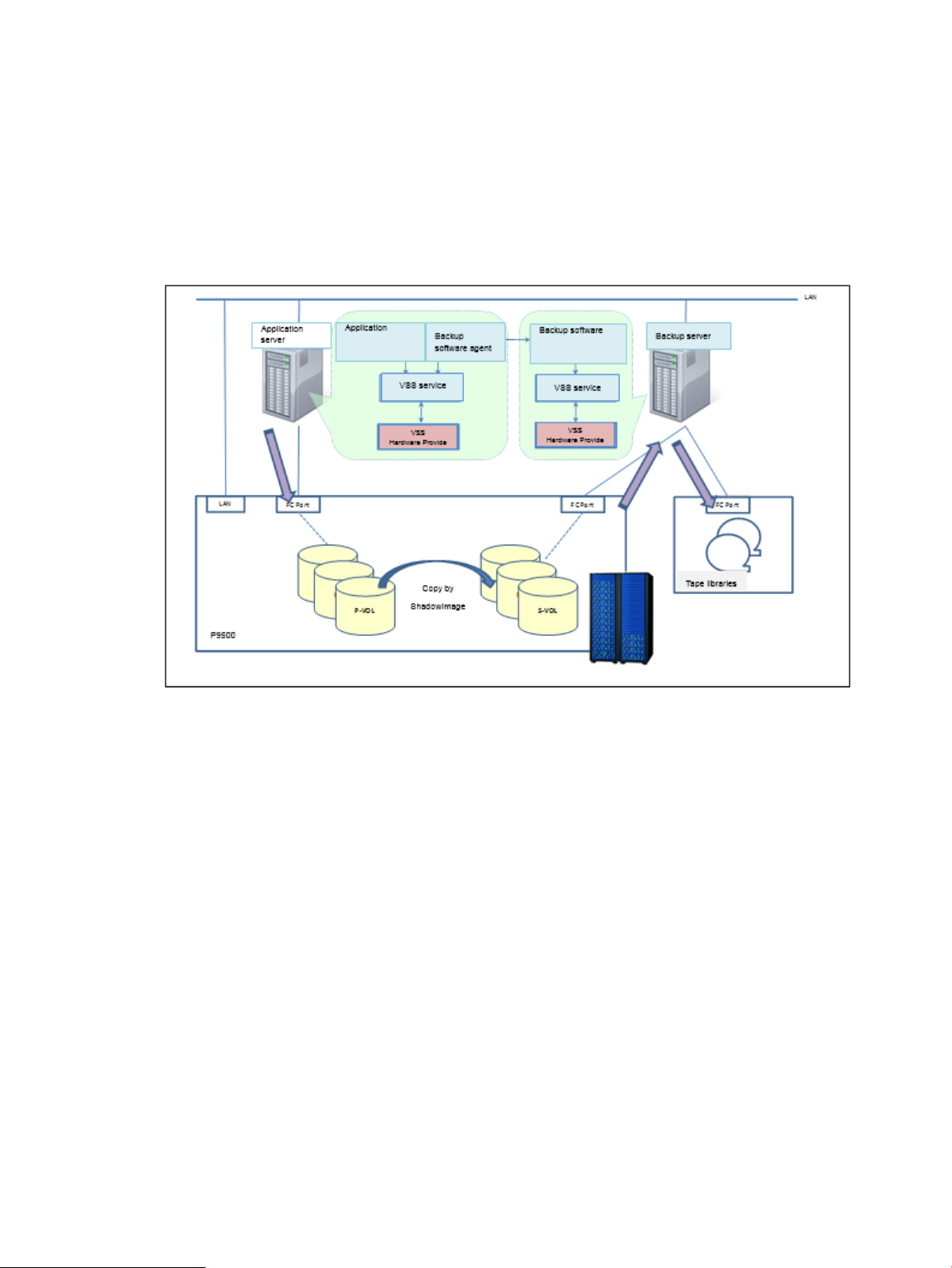
Packard Enterprise disk array systems such as the XP P9500 and the XP7. This program delivers
backup integration operations with VSS. This program provides the following functions:
• VSS provider — HPE XP Storage Adapter for Microsoft® Volume ShadowCopy Service is
a fully-functional VSS implementation. The provider performs copy control of the Business
Copy or Snapshot pair in the disk array system targeted for a backup.
• GUI tools — With the GUI tools you can confirm and set up the configuration necessary for
the VSS Provider's operation.
Figure 2 Backup image
Overview of the VSS Provider 11
Page 12

2 Environmental Prerequisites
System configuration
The system configuration requirements for VSS Provider are shown below.
• The HPE VSS Hardware provider must be installed on both the backup and recovery
application server (such as the media server in a Symantec NetBackup environment) and
the application server (such as a Microsoft Exchange server) from which a backup will be
taken.
• Table 1 (page 12) shows the connection of I/O path between servers and disk array systems
and the connection that VSS Provider gives an operation direction to the disk array systems
for FC environment support.
• In the case of XP P9500/XP7, the command device must be mapped on an application
server and a backup server.
• IPv6 is not supported.
• Fiber channel switches are not always required. Use them according to your environment
as needed.
• Multiple disk array systems can be connected to both an application server and a backup
server.
• For the application server, a cluster configuration using MSCS (MSFC) is also possible. (For
the backup server, this configuration is impossible.)
• The necessity of using the same operating system on both the backup server and the
application server depends on the backup software.
Table 1 Server and disk array systems connection
Examples of supported system configurations
VSS Provider supports the following system configurations.
Figure 3 (page 13) shows a similar configuration using a XP P9500/XP7 disk array system.
Connection between servers/disk array systems for
FC environment
I/O pathHost portDisk array system
Path for an operation
direction
Must be connected with FCMust be connected with FCFCXP P9500/XP7
12 Environmental Prerequisites
Page 13
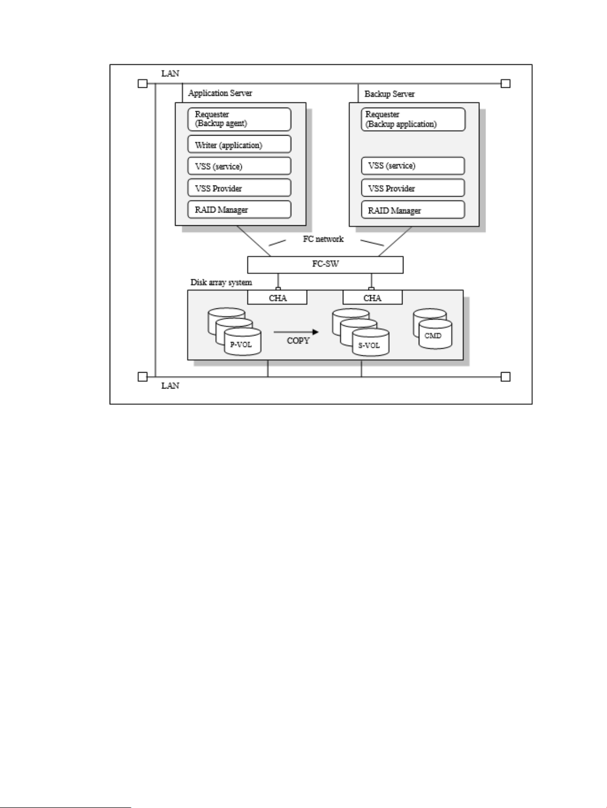
Figure 3 Example of a VSS provider system configuration [XP P9500/XP7]
Example of VMware Guest to Guest Backup (FC) function system configuration
VMware Guest to Guest Backup (FC) function is that VSS Provider backups P-VOL connected
to ESXi with FC and VM on ESXi is used as an import server of replicated secondary VOL.
In case of using the VMware Guest to Guest Backup (FC) function, the following system
configurations are supported.
Nontransportable configuration
This is the configuration to backup in the Nontransportable configuration in which the secondary
VOL is imported to the virtual machine to be used as the application server.
System configuration 13
Page 14
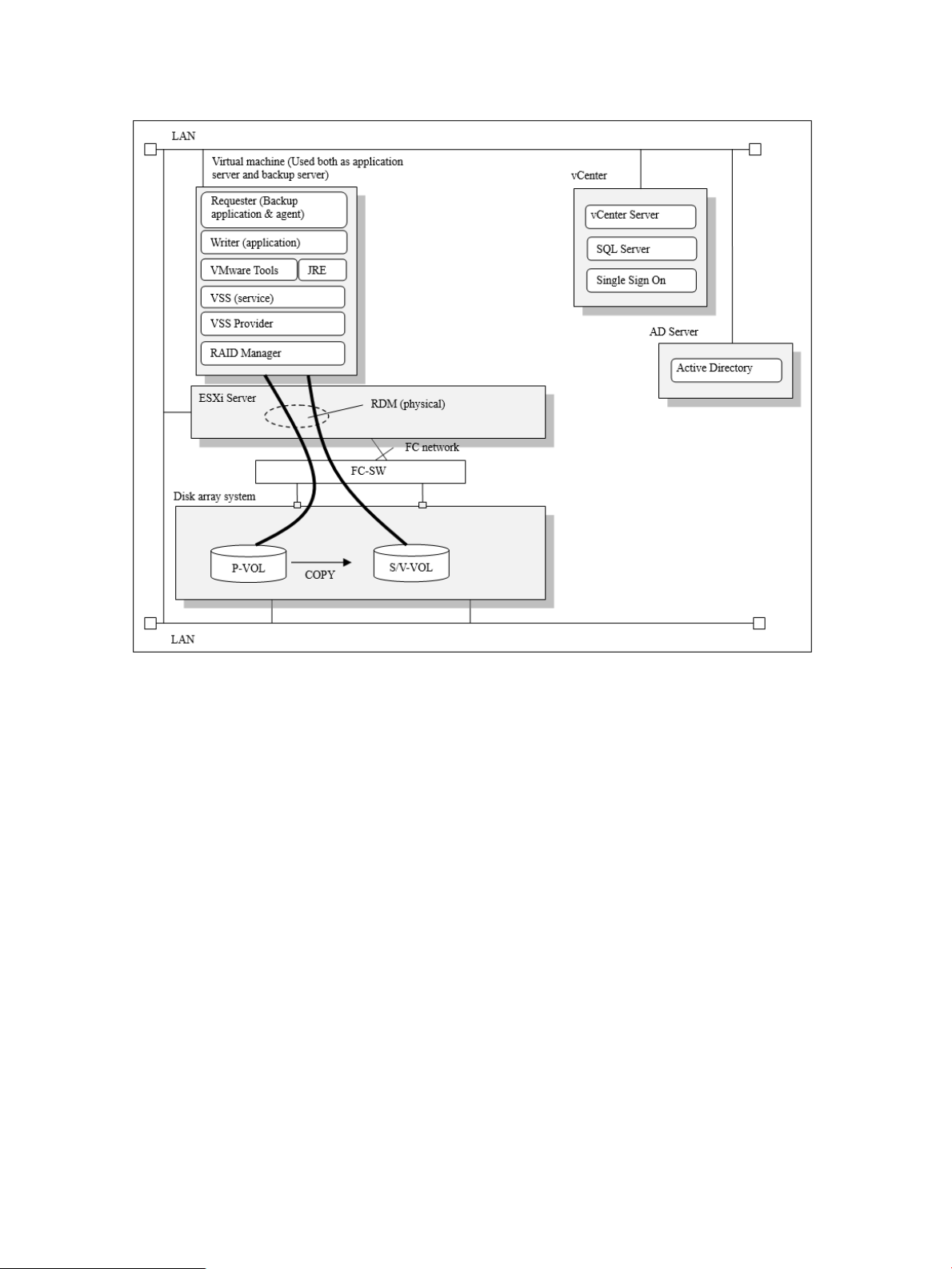
Figure 4 Example of VMware Guest to Guest Backup (FC) function system configuration
(Nontransportable configuration)
Transportable configuration (one ESXi)
This is the configuration in which the virtual machines for the application server and backup
server uses are located on the same ESXi.
14 Environmental Prerequisites
Page 15
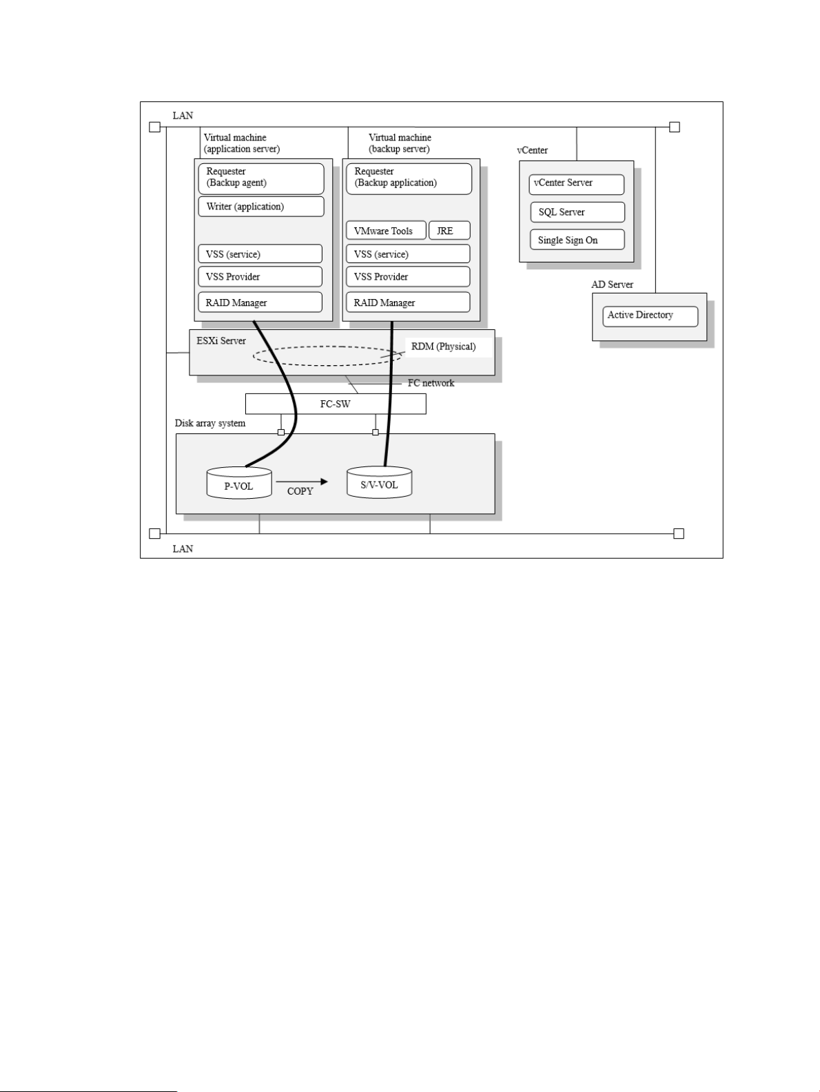
Figure 5 Example of VMware Guest to Guest Backup (FC) function system configuration
(Transportable configuration (one ESXi))
Transportable configuration (separate ESXi)
This is the configuration in which the virtual machines for the application server and the backup
server uses are located on the separate ESXi.
System configuration 15
Page 16

Figure 6 Example of VMware Guest to Guest Backup (FC) function system configuration
(Transportable configuration (separate ESXi))
16 Environmental Prerequisites
Page 17
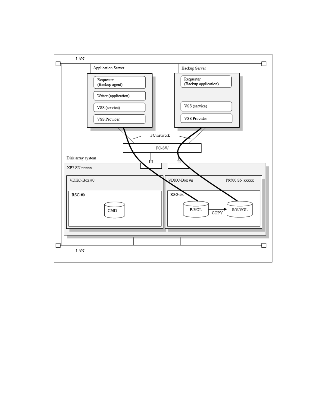
Examples of Ext Stor configuration
VSS Provider supports the following Ext Stor configurations.
Figure 7 Example of Ext Stor configuration (Post P9500 migration) (one physical DKC)
System configuration 17
Page 18
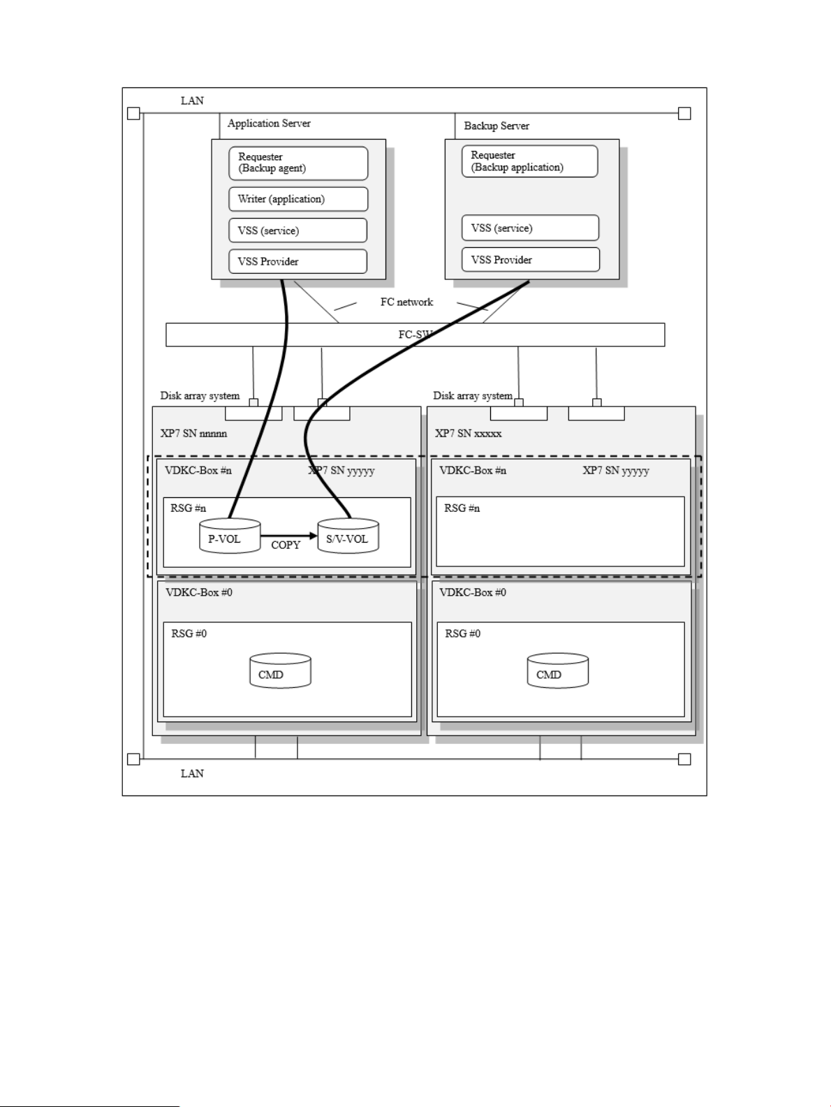
Figure 8 Example of Ext Stor configuration (two physical DKCs)
Example of HA configuration
VSS Provider supports the following HA configurations.
18 Environmental Prerequisites
Page 19
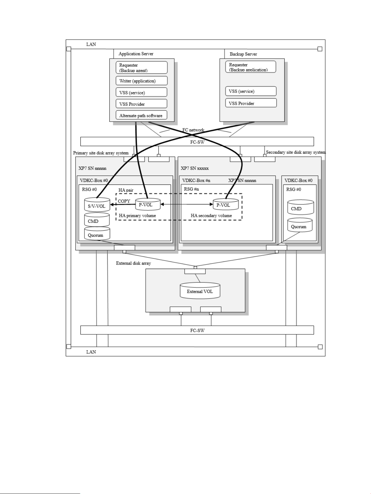
Figure 9 Example of HA configuration
Server prerequisites
Prerequisites for application and backup servers:
• CPU — Must be more than or equal to the recommended requirements of the OS.
Windows Server 2008 R2, 2GHz or higher◦
◦ Windows Server 2012, 3.1GHz or higher
• Memory — Must be more than or equal to the recommended requirements of the OS.
Windows Server 2008 R2, 2G bytes or higher◦
◦ Windows Server 2012, 8G bytes or higher
Server prerequisites 19
Page 20

• Disk drive free space — Disk capacity including log files and setup files are required because
log files and setup files are not included.
NOTE: Depending on the specified log file size and the number of generations, a very
large amount of disk space may be required. Logs cannot be output when a disk has no free
space.
◦ 4 gigabytes or more if using the default log file size and number of generations
◦ 152 gigabytes or more if the log file size and the number of generations are set to
maximum
Formula for calculating the required disk size [GB]:
Disk size [GB] = (6 x specified log file size [MB] x (number of generations +1) +1,585 ) ÷
1024
NOTE: The log file size and the number of generations can be specified by using the
maintenance configuration files. For details, see “Maintenance configuration files” (page 42)
and “Generation management of log files” (page 65).
• Display — Required for the GUI tool
Screen resolution – 1024 x 768 pixels or more◦
◦ Screen color – 24 bits or more
• Supported HBA — What the OS permits
20 Environmental Prerequisites
Page 21

Software prerequisites
Operating systems
VSS Provider supports the following versions of Microsoft Windows Server:
• Windows 2008 Server, 64-bit versions, including the following (Server Core option can be
specified):
◦ Windows Server 2008 R2, Standard Edition
◦ Windows Server 2008 R2, Enterprise Edition
◦ Windows Server 2008 R2, Datacenter Edition
◦ Windows Server 2008 R2, Standard Edition SP1
◦ Windows Server 2008 R2, Enterprise Edition SP1
◦ Windows Server 2008 R2, Datacenter Edition SP1
• Windows Server 2012, 64-bit versions, including the following (Server Core option can be
specified. Only classic style desktop is supported.):
◦ Microsoft Windows Server 2012 Standard Edition
◦ Microsoft Windows Server 2012 Datacenter Edition
◦ Microsoft Windows Server 2012, R2 Standard Edition
◦ Microsoft Windows Server 2012, R2 Datacenter Edition
Virtual environments
VSS Provider supports the following virtual environments:
• Hyper-V and Hyper-V 2.0:
Disk Connection Configuration — Path-through◦
◦ Server Configuration:
– Non Transportable — Not Supported
– Transportable Configuration Application Server — Supported
– Transportable Configuration Backup Server — Not Supported
• Hyper-V 3.0
Disk Connection Configuration — Path-through, and Virtual Fibre Channel◦
◦ Server Configuration
– Non Transportable — Supported (not supported with Path through connection)
– Transportable Configuration Application Server — Supported
– Transportable Configuration Backup Server — Supported (not supported with Path
through connection)
• ESXi 5.1 update1 and ESXi 5.5
Disk Connection Configuration — Raw Device Mapping (Physical Compatibility)◦
Server Configuration:
Software prerequisites 21
Page 22

Software
Table shows the software that is needed in order to use VSS Provider.
◦
Guest to Guest Backup (FC) function)
Non Transportable — Supported (Raw Device Mapping, corresponding to VMware
–
– Transportable Configuration Application Server — Supported
– Transportable Configuration Backup Server — Supported (Raw Device Mapping,
corresponding to VMware Guest to Guest Backup (FC) function)
VersionUsageStorage/OSSoftware
XP P9500RAID Manager
Business Copy, Snapshot
(SS), and Snapshot (FS)
function.
XP7
Business Copy function or
Snapshot (FS) function.
Virtual DKC(Ext Stor)
Business Copy, Snapshot
(SS), and Snapshot (FS)
function.
v01.32.06 and laterRequired for a backup using
v01.32.06 and laterRequired for a backup using
v01.32.06 and laterRequired for a backup using
Services
To use VSS Provider, start Volume Shadow Copy Service manually or automatically.
The software required to use the VMware Guest to Guest Backup (FC) function
To use the VMware Guest to Guest Backup (FC) function, the software listed is required.
• JRE 1.7(x64) — Required to be installed in the virtual machine in which the secondary VOL
(S-VOL/V-VOL) copied by VSS Provider is imported.
Since JRE is not included in the installer of VSS Provider, JRE installation is required when
implementing VSS Provider.
• VMware vCenter Server — Required to build 5.1 update1 b or 5.5 a.
• VMware Tools — Required to be installed in the virtual machine in which the secondary VOL
(S-VOL/V-VOL) copied by VSS Provider is imported.
Support scope of Ext Stor configuration
This subsection indicates the support scope of Ext Stor configuration.
RSG
Supported configurations
• One RSG in VDKC-Box
• One RSG in respective multiple VDKC-Boxes
• One RSG each in virtual DKC which straddles multiple physical DKCs
NOTE: Two or more RSGs in VDKC-Box is not supported
22 Environmental Prerequisites
Page 23
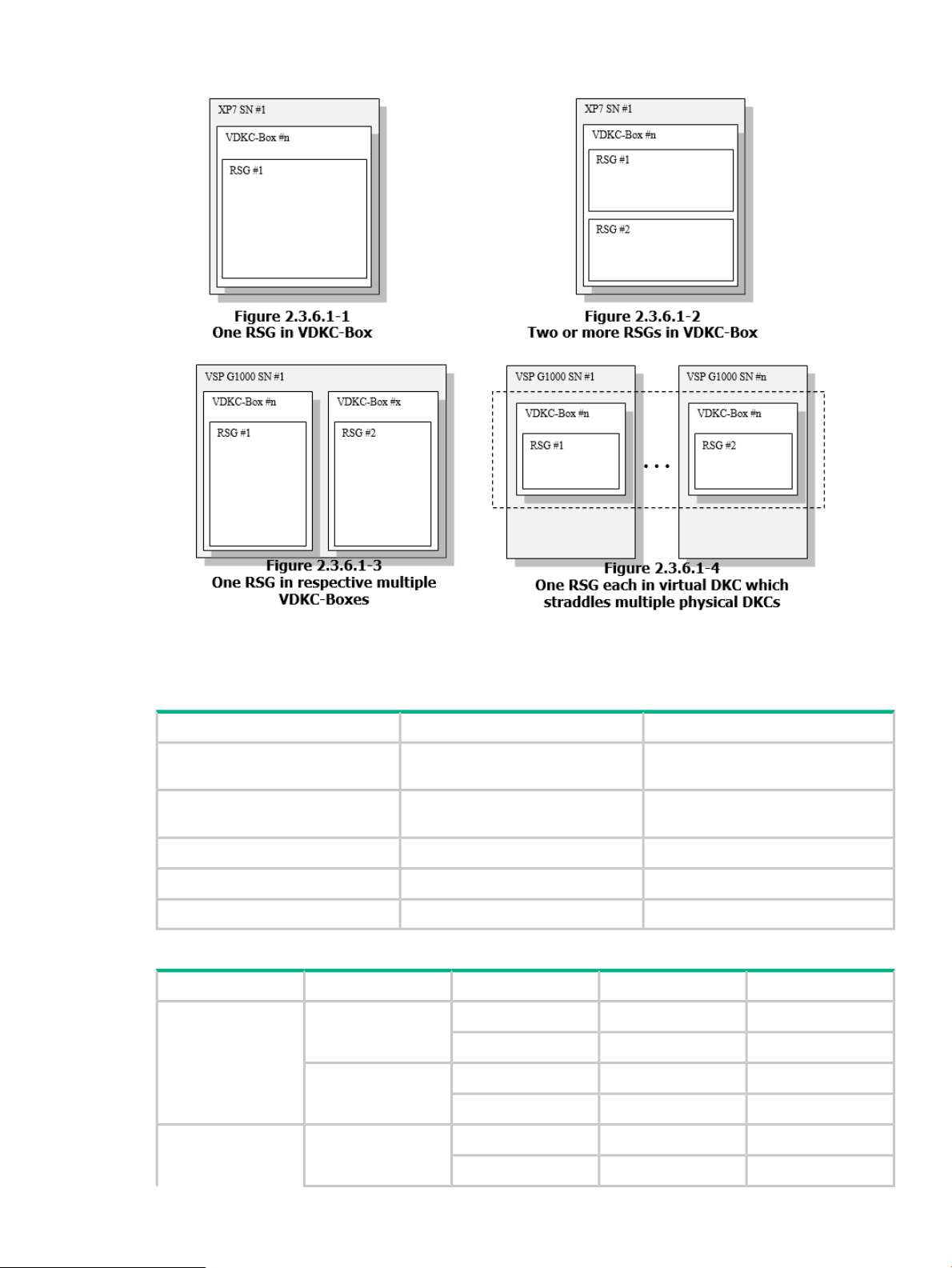
Figure 10 RSG configurations
RSG assignment of each resource
Table 2 Requirement of assigning resources to meta_resource
Table 3 Support scope of RSG assignment of each resource
P-VOL
RemarksAssignment to meta_resourceResource
RequiredEvery Port
RequiredEvery Parity Group
Do not careEvery LDEV_ID
Do not careEvery Host Group ID
Do not careEvery Pool (THP/Smart/FS)
Do not assign every port and every
parity group to non-meta_resource.
Do not assign every port and every
parity group to non-meta_resource.
SupportPrivilege for RSGRSG AssignmentResource
SupportedWith privilegeSame RSG as P-VOLPhysical LDEV ID
Non-SupportedWithout privilege
Non-SupportedWith privilegeDifferent RSG from
Non-SupportedWithout privilege
SupportedWith privilegeSame RSG as P-VOLVirtual LDEV ID
Non-SupportedWithout privilege
Software prerequisites 23
Page 24
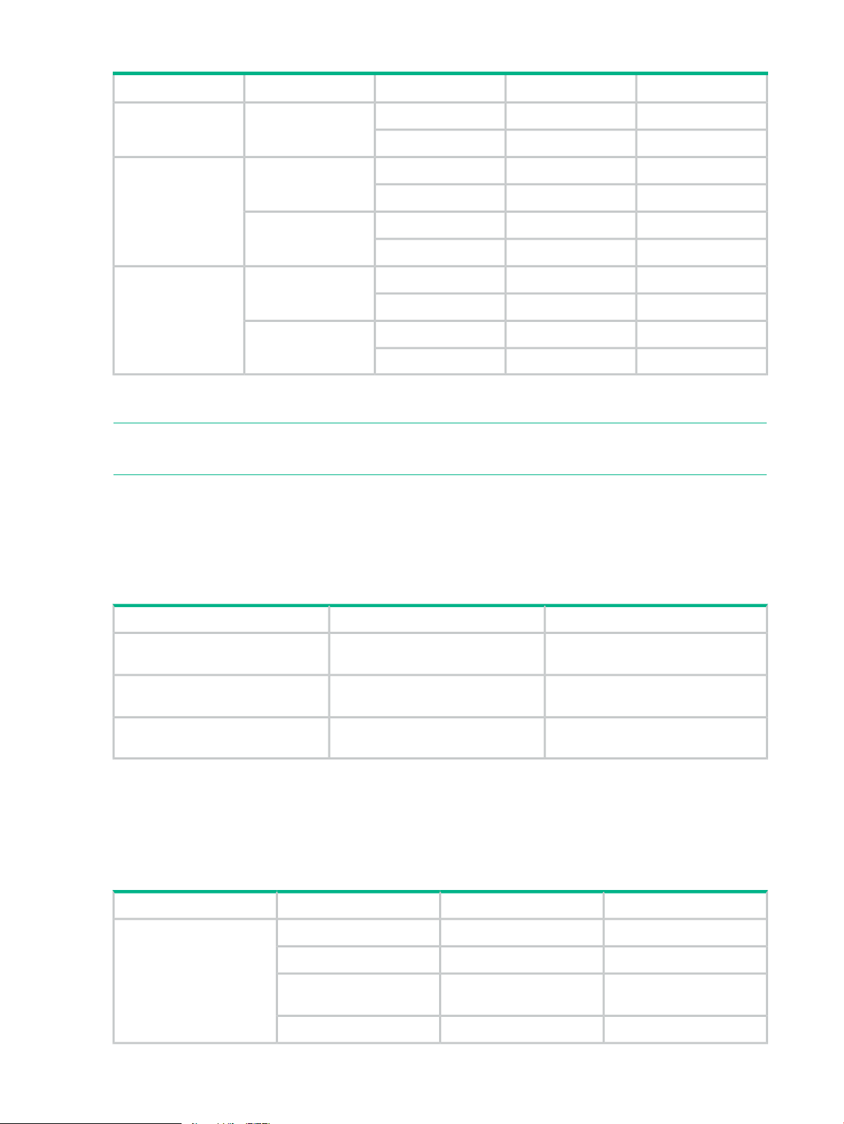
Table 3 Support scope of RSG assignment of each resource (continued)
SupportPrivilege for RSGRSG AssignmentResource
Non-SupportedWith privilegeDifferent RSG from
P-VOL
P-VOL
Non-SupportedWithout privilege
SupportedWith privilegeSame RSG as P-VOLHost group ID
Non-SupportedWithout privilege
Non-SupportedWith privilegeDifferent RSG from
Non-SupportedWithout privilege
1
P-VOL
1
Pool is not managed by RSG. However, a pool created only by LDEV which belongs to specific RSG can only be used
by a user who has RSG privileges.
SupportedWith privilegeSame RSG as P-VOLPool (THP/Smart/FS)
Non-SupportedWithout privilege
SupportedWith privilegeDifferent RSG from
Non-SupportedWithout privilege
NOTE: Even if P-VOL to be operated is assigned in meta_resource, it can be used if a user
has appropriate privileges.
Placement location of command device which is connected to host
Place a command device in each physical DKC when a command device is used in multiple
virtual DKCs.
Table 4 Support scope of placement location of command device which is connected to
host
SupportedOnly command device in physical
DKC
Non-SupportedOnly command device in virtual DKC
RemarksSupportPlacement location
Connecting only command device in
physical DKC to host is required.
and virtual DKC
Support scope of HA configuration
This subsection indicates the support scope of HA configuration.
Adapter function
Table 5 Support scope of adapter function
operations
24 Environmental Prerequisites
Same as above.Non-SupportedCommand device in physical DKC
RemarksSupportFunctionTarget
SupportedCreation of secondary VOLPrimary site only
SupportedRemoval of secondary VOL
SupportedSecondary VOL pair
SupportedSecondary VOL mapping
Page 25

Table 5 Support scope of adapter function (continued)
RemarksSupportFunctionTarget
operations
site at the same time
operations
Supported functions for Primary site:
• Creation of secondary VOL
• Removal of secondary VOL
• Secondary VOL pair operations
• Secondary VOL mapping
Supported functions for Secondary site:
SupportedCreation of secondary VOLSecondary site only
SupportedRemoval of secondary VOL
SupportedSecondary VOL pair
SupportedSecondary VOL mapping
Not SupportedCreation of secondary VOLPrimary site / Secondary
Not SupportedRemoval of secondary VOL
Not SupportedSecondary VOL pair
Not SupportedSecondary VOL mapping
When VOL at the secondary
site is operated, replace
primary volume with
secondary volume of HA
pairs. See the high
availability User Guide.
NOTE: When VOL at the secondary site is operated, replace primary volume with secondary
volume of HA pairs. See the high availability User Guide.
• Creation of secondary VOL
• Removal of secondary VOL
• Secondary VOL pair operations
• Secondary VOL mapping
NOTE: Operation of these functions are not supported on the Primary or Secondary site at
the same time.
Placement location of command device which is connected to host
In the case of the HA configuration, place the command devices in both the storages at the
primary site and the secondary site.
For the support scope of the placement location, see Table 4 (page 24).
Storage requirements
Storage requirements when using VSS Provider.
Storage requirements 25
Page 26
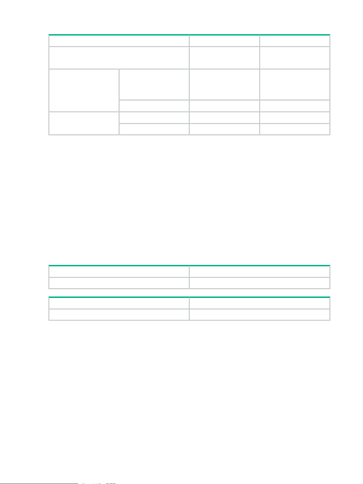
Table 6 Storage requirements
RemarksDescriptionItem
XP P9500Support type
XP7
Storage requirements for XP 9500:
• Microprogram revision — 70-06-20-00/00 or higher
Required for a backup using Business Copy function, Snapshot(SS), or Snapshot(FS)
function
• Host port — FC
Storage requirements for XP7:
• Microprogram revision — 80-02-20-00/00 or higher
• Host port — FC
Restrictions and points of consideration
70-06-20-00/00 or higherXP P9500Microprogram revision
80-02-20-00/00 or higherXP7
FCXP P9500Host port
FCXP7
Required for a backup using
Business Copy function,
Snapshot(SS), or
Snapshot(FS) function
Restrictions and points of consideration related to the environmental configuration
DescriptionItem
(Missing number)(Missing number)
DescriptionItem
(Missing number)(Missing number)
Server Account Authentication
In case of using VSS provider as the general user, server information and disk array system
information cannot be retrieved. Administrative right should be given to the server account.
Also, in case of Windows Server 2008 or later and use VSS Provider with the Windows logon
account having the Administrator rights other than the built-in Administrator, server information
and disk array system information cannot be retrieved.
VSS Provider can be used by disabling UAC though, using VSS Provider with the Windows logon
account having the Administrator right is recommended.
Environmental configuration via remote desktop
Configuration via a remote desktop is supported.
Installation, repair installation, uninstallation and update installation are possible.
26 Environmental Prerequisites
Page 27

Items to confirm during installation
• Disable antivirus processes and other monitoring process services (daemon processes). If
such services (daemon processes) are active, installation may not be possible.
• When using firewall software other than the Windows firewall, disable or remove the software
during installation. In addition, allow settings for communication with TCP port 2000 after
installation.
• Other software must not use TCP port 2000.
Installation drive
Install only on local drives.
Installation on network drives and removable disks is not supported.
Path length of the installation folder
Installation folder of VSS Provider can be specified at the time of installation. Note that the path
length of the VSS Provider installation folder must be less than or equal to 200 bytes
Number of LUs which can be mapped to the host group
Up to 255 LUs per host group are recognizable by Windows (For details, visit
http://support.microsoft.com/kb/310072/en-us ).
Since WWN of the backup server maps S-VOL for a backup to the registered host group, if the
host LUN number is 255 or more, S-VOL cannot be recognized due to Windows specification
mentioned above and backup processing fails.
In addition, the following error is output in the event log. <Event ID 12362>
How to create setup, maintenance configuration, and configuration files
Use the configuration files which are automatically created during VSS HW provider installation.
Files that are made by other means (by text editor or the like) may be overwritten during
installation, repair installation or update installation.
If you delete a file by mistake, restore the file by VSS HW provider repair installation and
reconfigure the necessary information as explained in “User edit files” (page 37).
Hewlett Packard Enterprise shortcut of the Start Menu
When installation/uninstallation is performed by multiple Windows accounts on the equivalent
server, "Hewlett Packard Enterprise" shortcut may be left for the Start Menu of Windows at the
time of uninstallation. You may ignore it, but you can delete it.
To delete the shortcut:
1. Log off in the account except the Windows account that uninstalled VSS Provider.
2. Confirm whether there is Hewlett Packard Enterprise folder for the Start Menu of each
following Windows accounts and delete it if it exists.
<system drive>:\Users\<Windows
account>\AppData\Roaming\Microsoft\Windows\Start Menu\Programs
3. Confirm whether there is Hewlett Packard Enterprise folder for the Start Menu of the ALL
user and delete it if it exists.
<system drive>:\ProgramData\Microsoft\Windows\Start Menu\Programs
Restrictions and points of consideration 27
Page 28

Installation of other VSS Provider
Installation of following other VSS Providers at the same time is not supported.
• HPE Storage VSS Hardware Providers
• Hitachi Storage Adapter for Microsoft Volume ShadowCopy Service
Account Authentication
Select Administrator (View and Modify) from the role check box in the Storage Management
Software account addition window.
For the characters and can be used for user name and password as well as the number of
characters can be entered, refer to the RAID Manager command reference.
RAID Manager (HORCM)
• Start RAID Manager (HORCM) prior to starting any RAID Manager commands from VSS
Provider.
See “Preparing configuration files and restarting RAID Manager (HORCM)” (page 43) for
details.
• In the case of the Ext Stor configuration or HA configuration, do not describe HORCM_VCMD
in the HORCM CONF configuration file.
• Do not use the HORCM CONF configuration file used by VSS Provider except for the purpose
of VSS Provider.
Host group creation
Host groups must be created in disk array systems, see Table 7 (page 46).
Creating a user authentication account for storage administration
The disk array system must have the same user name and password when using multiple disk
array systems of the XP P9500/XP7.
For example:
When using disk array system A or B, the same user name (USER01) and password (*****) must
be used.
• Storage A:
User name — USER01◦
◦ Password — *****
• Storage B:
User name — USER01◦
◦ Password — *****
28 Environmental Prerequisites
Page 29

Assigning LDEV ID
• When configuring Ext Stor, to create secondary VOL (S-VOL/V-VOL) using VSS provider
and GUI, assign the physical LDEV ID to RSG which P-VOL belongs to, in advance.
• Assign virtual LDEV ID to physical LDEV ID as well.
(Do not operate the physical LDEV ID to which the virtual LDEV ID has not been set (Virtual
LDEV ID will be FF:FE) or the physical LDEV ID reserved for HA (Virtual LDEV ID will be
FF:FF))
• In the case of using virtual DKC which straddles multiple physical DKCs, make sure that
virtual LDEV ID is not duplicated in virtual DKC.
Resource Group (Resource Partition)
Do not create Resource Group other than meta_resource in the storage system because Resource
Group is not supported.
Exceptionally, this restriction can be relaxed under H-UVM configuration. See “Support scope
of Ext Stor configuration ” (page 22).
Raw Device Mapping (RDM)
LU which is used as P-VOL must be mapped on the application server in RDM (physical
compatibility mode).
Command device
In case of using XP P9500/XP7 disk array systems, command device must be mapped on the
application server/backup server in RDM (physical compatibility mode)
SCSI controller type
SCSI controller type of the virtual machine supports LSI Logic SAS.
SCSI controller created by VSS Provider
If RDM required sufficient free virtual device node is not available on the import destination virtual
machine during the secondary VOL import process, VSS Provider creates SCSI controller using
the following settings.
• SCSI controller number — Use from not created and smaller controller number
• SCSI controller type — LSI Logic SAS
• Sharing SCSI path — Nil
VMware HA
To use VMware HA, the following conditions must be fulfilled:
• WWN used for the failover of the node participating in VMware HA, write in the configuration
file using the “WWN of ESXi” specified option.
• Register the above WWN in HG which is used for VSS Provider.
• Confirm that the failover operates by using the corresponding HG in advance.
Restrictions and points of consideration 29
Page 30

Operational restrictions and points of consideration
The following table lists the concerning restrictions and points of consideration related to operation
when using VSS Provider.
DescriptionItem
(Missing number)(Missing number)
Multiple instances of the VSS Provider
Multiple instances of the GUI tools tools on one server are not supported.
Unregistering a disk array system
To unregister a disk array system registered by the Add Storage function of the GUI tool, remove
the IP address and the serial number from the setup file.
Number of user accounts that can be registered for a disk array system
Use the Add Storage function of the GUI tool to register user accounts.
Only one account can be registered for a disk array system.
To change a user account, you must re-register the disk array system using the Add Storage
function and specify a new user name and a password.
Changing the configuration file or the maintenance configuration file
The VSS HW provider GUI will need to be restarted when a change to the configuration file or
the maintenance configuration file are made while they are in use.
Restarting a server during a backup
When the server reboots during a backup, depending on the backup software and the timing of
a server reboot, the pair state will be PSUS or PAIR after resynchronization is completed.
When a pair status is suspended, perform the confirmation and recover steps outlined in
“Confirmation and support after a recovery” (page 135).
Log collection during problem occurrence
Because a log may wrap, collect a log and save it during the problem occurrence.
See “Information collected during problem occurrence” (page 137) for the log to collect.
Parallel backup of multiple data on the same volume
When performing a parallel backup of multiple data located on the same volume, the following
operational restrictions exist.
• Backup with Business Copy — Unsupported
• Backup with Snapshot — No restrictions
30 Environmental Prerequisites
Page 31

Event logs which the VSS service outputs
• When importing is performed normally during a backup processing, the following application
event log errors may be output.
◦ Event ID 8193,12289
Visit the following for details:
http://support.microsoft.com/kb/2003016/en-us
• During a backup processing, the following application event log errors are output, and backup
processing may fail:
◦ Event ID 12362,12363 Referring to Chapter 2, 3 and 8.4, confirm prerequisites
have been completed.
In case of using VMware Guest to Guest Backup (FC) function, confirm that the
description stated in “WWN of ESXi” of the configuration file is correct. See “Setup files”
(page 38).
Follow the flow chart in Figure 8-3 and refer to the event log which the VSS Provider
outputs and the VSS Provider log. If an error does not occur, because it is thought that
the VSS Provider works normally and the volume is not recognizable due to the problem
of the plug and play for Windows, contact Windows support center.
◦ Event ID 12329,12330
Referring to Chapter 2, 3 and 8.4, confirm prerequisites have been completed. Follow
the flow chart in Figure 8-3.
◦ Event ID 12293
Visit the following for details:
http://support.microsoft.com/kb/972135/en-us
◦ Event ID 12297
Visit the following for details:
http://technet.microsoft.com/en-us/library/dd364933(v=ws.10).aspx
◦ Event ID 12298
Visit the following for details:
http://technet.microsoft.com/en-us/library/cc734401(v=ws.10).aspx
It is recommended to monitor Windows event log to detect a problem early because there is a
case that the backup software cannot detect the error output by the VSS service.
Event log which does not affect the VSS Provider operation
The following event logs which do not affect the VSS Provider operation may be output while
using VSS Provider.
• VSS Service related
Refer to Event logs which the VSS service outputs in Table 2.5.2-1.
• HDLM related
When a backup finishes normally in an HDLM environment, the following event log is output:
(HDLM outputs event logs when VSS Provider is unmapped.)
Restrictions and points of consideration 31
Page 32

For details, see the HPE XP7 dynamic link manager software user's guide (for Windows(R)
in the Hewlett Packard Enterprise Software manual. Refer to the descriptions of Windows
event logs and the messages that HDLM outputs.
Event IDSourceLog type
32787DLMManagerApplication
32790DLMManager
32794DLMManager
20781hdlmdsmSystem
• [VDS Service related]
Event IDSourceLog type
1VDS Basic ProviderSystem
1Virtual Disk ServiceSystem
The operative restrictions of the concurrence configuration change for the equivalence disk array system
In disk array system specifications, a concurrence configuration change is executed for the
equivalent resource, unexpected configuration change is executed each other and the expected
configuration may not be made.
Therefore, for the resource that VSS Provider/GUI tool changes configuration of, the following
operative restrictions are necessary.
• Do not execute a concurrence configuration change from other applications (Storage
Management Software and so on).
• Make out the schedule not to execute a concurrence configuration change using VSS Provider
/GUI tool from other servers.
• Restart VSS Provider/GUI tool when you change the setting of a priced option in the disk
array system.
A volume status at the time of ResyncLuns abnormal finish
P-VOL remains in an off-line status to protect the consistency of data when a failure occurs in
restore processing by ResyncLuns.
Make target LUN an online status from Server Manager -> Disk Management as needed.
For details, visit the following.
http://support.microsoft.com/kb/2668865
Specifying WWN of the import server from the configuration file
VSS Provider executes the import processing by obtaining WWN of HBA on the secondary VOL
import server. If WWN is not available from HBA due to any reason, you can specify WWN of
the import server using “WWN of ESXi” specified option of the configuration file, see “Setup files”
(page 38).
32 Environmental Prerequisites
Page 33

NOTE: If you have specified WWN which is different from the intended import server in the
storage, VSS Provider imports the secondary VOL to the server having the specified WWN and
the process is completed successfully. Then, an error is not found in the VSS Provider log, and
an error message that the target volume is not recognized is output to the event log by the VSS
service.
In this case, make sure that WWN listed in the “WWN of ESXi” specified option is correct.
WWN listed in the “WWN of ESXi” specified option imports the secondary VOL for all HG
configured in the target storage.
The number of the target backup volume
Depending on the configuration of the backup target and system loading status, pair split
processing time exceeds the VSS prescribed time and which may lead to the backup failure.
If frequent timeout occurs in the pair split processing, reviewing the configuration of the backup
target and system loading status is recommended.
Owner node of virtual machine on shared volume
When backing up virtual machines located in the shared volume (CSV) of the failover cluster of
Windows2012 or later, VSS service error may occur, which may lead to the backup failure.
http://msdn.microsoft.com/en-us/library/windows/desktop/aa384620%28v=VS.8 5%29.aspx
If this failure occurs frequently, consolidating the owner node of the virtual machine in one node
is recommended.
Confirmation procedure:
1. Deploy the target cluster from the failover cluster manager and click Role.
2. Check Owner node of the virtual machine displayed in the Role list.
3. If owner node is located in multiple nodes, consolidate in one node.
Backup from multiple servers and virtual machines at the same time
When backing up from multiple servers and virtual machines at the same time, waiting time for
obtaining resource of the disk array system or command competition occurs, which may lead to
the backup failure.
In this case, take one of the following actions.
• Change Waiting time for resource lock/Waiting time for obtaining the privilege to
Modify and The number of VSSHP retries of the setup file to adjust the waiting time for
obtaining resource and the number of retries of the disk array system. See “Setup files”
(page 38).
• Review the schedule setting at the requester side to avoid coinciding the time frame between
the startup time of the backup job and the completion of the backup job (arrow shown below).
RAID level
RAID1, RAID5, and RAID6 are supported.
Emulation type
OPEN-V is supported.
Restrictions and points of consideration 33
Page 34

Confirming the resource lock
Resources are locked while changes are being made (for example, during LDEV creation).
Resources must be unlocked for a backup to proceed.
If a resource is locked during a backup, VSS Provider retries until the VSS can obtain resources.
However, the backup fails when the resources cannot be obtained even if a retry is performed.
Schedule backups for times when resources will be unlocked.
NOTE: The status of resources can be confirmed by the Raidcom get resource command
of RAID Manager. For details, see the RAID Manager User’s Guide
Restrictions on using together with RAID Manager
The following restrictions apply when you use RAID Manager on the same server while operating
the VSS Provider.
Do not use the same user account for RAID Manager as VSS Provider uses for user authentication
(a user account of Windows or a user name for the user authentication of the disk array system).
<User who uses VSS Provider >
User name for the user
authentication of the disk array
systemWindows user accountApplication
SystemVSS Provider
Windows logon accountGUI tool
User used when registered using the
Add Storage function of GUI tool.
User used when registered using the
ADD Storage function of GUI tool.
LUSE Volume
Unsupported
Operation when Online Migration is running
Unsupported
Multiple generation management by enabling Snapshot resync mode
When Snapshot resync mode is enabled, the created V-VOLs are retained in PAIR status.
Therefore, splitting pairs enables management of multi-generational data. However, deleting
V-VOLs cannot be performed automatically. Delete the V-VOLs in PAIR status that become
unnecessary with the change in the generation numbers to be managed by using the Storage
Management Software or GUI tools
External Storage (Ext Stor)
The Ext Stor supports operations on the virtual DKCs only for supported physical DKCs. Even
if unsupported models are migrated to supported models by using NDM, VSSHP does not support
these migrated models. ?
Server to be registered using the Register Server function
With the Register Server function of the GUI tool, register vCenter Server controlling ESXi.
Account authorization of vCenter Server
Give the Administrator authority to the Window logon account for the server configuring vCenter
Server specified with the Register Server function of the GUI tool.
34 Environmental Prerequisites
Page 35

Unregistering the registered vCenter Server account
Do not unregister the vCenter Server account by using the Register Server function of the GUI
tool during the backup operation with VSS Provider.
Deleting S-VOL/V-VOL from the GUI tool
Prior to deleting S-VOL/V-VOL, confirm that RDM has not been connected to a virtual machine
other than the virtual machine in which the GUI tool is used by the S-VOL/V-VOL to be deleted.
NOTE: All-Paths-Down (APD) or Permanent Device Loss (PDL) occurs if you delete
S-VOL/V-VOL which connected as RDM to another virtual machine by using the GUI tool.
Prior to deleting the target S-VOL/V-VOL, confirm that RDM has not been connected to another
virtual machine by using vSphere Client.
Instance number of RAID Manager
If VSS provider is used in the multiple virtual machines on the same ESXi at the same time,
instance number of RAID Manager should be different for each virtual machine.
For the details, see “Points to note when using VMware Guest to Guest Backup (FC) function”
in subsection 3.2.3.
• If the following error message is output in the VSS provider log, this error may fall under the
points to note stated above. In this case, review instance number of RAID Manager of each
virtual machine.
ERROR [E1000149] {CHiCommandProcessor::GetRaidcomXError}:Raidcom operation
returned an error response. Error: [Raidcom Error# 8
raidcom: [EX_OPTINV] A specified option is invalid
• Using up to four virtual machines operating on the same ESXi at the same time is
recommended.
If one of the following conditions is applied, check the usage status of VSS provider of other
virtual machines on the same ESXi and GUI tool.
Conditions:
• Failed to backup and the following message is output to VSS provider log.
• An error occurs in the GUI tool and the following message is output to the VSS provider log.
INFO [I1000031] {CHiCCI::CommandRetry(54321)}:returns: [5(10) :
[EL_CMDIOE] Control command I/O error, or rejected.
Operational restriction on the simultaneous configuration change for the same virtual machine
For the virtual machine in which VSS Provider/GUI tool are changing the configuration, do not
change the configuration by using vSphere Client and so on at the same time.
Restrictions and points of consideration 35
Page 36

3 Configuration Procedure
The configuration flow for VSS Provider:
• Installing the VSS Provider
Install VSS provider in an application server and a backup server. See “Installation” (page 36).
• Editing the setup files
Edit the setup files on the application server and the backup server. See “Setup files”
(page 38).
• Editing the maintenance configuration files
Edit the maintenance configuration files on the application server and the backup server.
See “Maintenance configuration files” (page 42).
• Editing the configuration files
Only when using XP P9500/XP7 storage devices, edit the configuration files on the application
server and the backup server. See “Preparing configuration files and restarting RAID Manager
(HORCM)” (page 43).
• Preparing storage devices
Configure the storage devices. See “Preparing a disk array system” (page 45).
• Registering the storage devices
Register the storage devices in VSS Provider using the GUI tool.
• Configuring each option of VSS Provider
Configure each option of VSS Provider using the GUI tool.
• Confirming environmental prerequisite of VMware Guest to Guest Backup (FC) function
Confirm that the environmental prerequisites are fulfilled just only when using the VMware
Guest to Guest Backup (FC) function. See “The software required to use the VMware Guest
to Guest Backup (FC) function” (page 22).
• Registering vCenter Server
Register vCenter Server in VSS Provider by using the GUI tool only when using the VMware
Guest to Guest Backup (FC) function.
Installation
VSS Provider must be installed on both the application server and the backup server. You can
install the VSS provider using an installer or from a command prompt.
NOTE: The following procedure uses version 04.X.X. Substitute the exe version to be used.("X"
is a revision number and it may be multiple digits (Ex: 04.14.10).
To install the VSS provider using the command prompt, do the following:
1. Open a command prompt.
2. Enter the installer file name.
Command prompt example:
c:\ >"HP-vssprovider-setup(04.14.x)-(x64).exe"
3. Press Enter.
To install the VSS provider using an installer, do the following:
1. Double-click the installer to start the installation wizard.
36 Configuration Procedure
Page 37

2. Click Next.
3. Choose the location for the software or use the default location (C:\Program
Files\HP\VSSProvider\).
When you want to change an installation destination:
a. Click Browse.
b. Select an installation folder.
When the installation folder is changed, a file is expanded under the new folder.
Only a local drive is supported as the installation drive.
Note that installation on a network drive or a removable disk is not supported. For the path
length of the installation folder, see “Restrictions and points of consideration related to the
environmental configuration” (page 26).
4. Click Next to start the installation. You will receive a message letting you know when the
VSS Provider is installed.
5. Click Finish to complete installation.
6. 1. Edit the configuration file in the installation folder. For the configuration file, see .
The log output level [DebugLevel=NORMAL] and the restore mode
[RestoreMode=NORMAL] are described in the configuration file by default.
As the restore mode is set in NORMAL by default, change the mode as needed. For the
Restore mode, see .
2. When using a disk array system of the XP P9500/XP7, copy the HORCM_CONF
configuration file (by default, horcm700.conf) stored in the installation folder to the
installation folder of RAID Manager (by default, <system drive>:\HORCM\etc folder).
For information about the HORCM_CONF configuration file, see . User edit files
User edit files
Setup and configuration files are created in the specified installation folder during the VSS Provider
installation. If a file already exists, the file remains and is not overwritten.
Users must edit each file as needed. See “Restrictions and points of consideration related to the
environmental configuration” (page 26) for the items to be edited in each file.
• Setup file (hivss.config)
Sets the behavior of VSS Provider. This includes items such as the Log output level of VSS
Provider and default backup mode.
• Maintenance c file (hilogger.config)
Sets the behavior of the log output function. This includes items such as log file size and
the number of log generations. See for the log generation management specifications.
• hiRaidcomX configuration file (hiRaidcomX.config)
Sets the instance number necessary to operate RAID Manager and the installation folder
for RAID Manager. This configuration file is only necessary for XP P9500/XP7 disk array
systems.
• HORCM CONF configuration file (horcm*.conf, * = the instance number)
Sets the system configuration to operate RAID Manager. This configuration file is necessary
for XP P9500/XP7 disk array systems. The instance number listed in hiRaidcomX.config
is indicated by an asterisk (*). The file name made when installing VSS Provider is
horcm700.conf. In this document, "*" is assumed to be 700 and the file name is assumed
to be horcm700.conf.
User edit files 37
Page 38

Setup files
Edit the setup files on the application server and backup server as needed.
Edit the files with a text editor using single-byte alphanumeric characters (SJIS code set). End
each line with a line feed.
Edit each item according to the backup needs of the user. Items which include brackets ([ ]) in
the list must be enclosed in single-byte brackets.
Setup file entries, description, and formatting:
• Comment — For entering comments.
RemarksItemDisk array system
(Missing number)(Missing number)(Missing number)
In the following cases, everything from "#" to the end of line is ignored as a comment:
◦ When there is "#" at the start of the line
◦ When there is "#" in the line; and
all blank spaces before “#”–
– IP address before “#”
◦ Formatting examples:
– #Comment One
– #Comment Two
– #Comment Three
– #Comment Four
– #Comment Five
• Lines consisting of only spaces or line feeds — Enter blank or line feeds when needed.
• Log output level — Specify the log output level for the log file.
You can change the log output level with the value of <level>.
See for the log output level to specify. NORMAL is the recommended value.
Formatting examples for [DebugLevel=<level>]:
◦ [DebugLevel=MINIMAL]
◦ [DebugLevel=NORMAL]
◦ [DebugLevel=VERBOSE]
◦ Blank (no entry)
• Default backup mode — When a backup mode is not specified by requester, specify the
backup mode by default. If neither specified from this item nor GUI tool, the default backup
mode adopts Business Copy.
Formatting:
◦ [DefaultBackupMode=BusinessCopy]
◦ [DefaultBackupMode=Snapshot]
38 Configuration Procedure
Page 39

NOTE: Similar mode can be specified from the GUI tool. If the setting was different between
GUI tool and the setup file, give priority to the setting specified in the setup file.
• WWN of ESXi — It is specified when using the VMware Guest to Guest Backup (FC) function.
It specifies WWN of the import destination ESXi in which the secondary VOL is imported at
the time of backup. Map S-VOL to HG in which WWN of <WWN> is registered during the
import processing of S-VOL. <WWN>should be specified in one-byte hexadecimal with 16
digits. When [wwn=<WWN>] are listed on the multiple lines, all listed WWNs will be the
mapping destination. Zoning of disk array system and WWN of ESXi need to be completed
in advance.
Formatting example for [wwn=<WWN>]:
[wwn=10000000C99267FC]
• The number of VSSHP retries — It specifies the number of retries when an error is detected
during the retrieval of the configuration information and configuration change of the disk
array system. It should be specified between 3 and 99 times. It is only applicable to VSS
provider. It is not applied to GUI tool. <the number of retries> should be specified in decimal
single-byte characters. If this value is omitted, or an invalid value is used, or the value is
outside the maximum and minimum values, the default value of 3 times is used.
Formatting example for [vsshp_retrycount=<the number of retries>]:
[vsshp_retrycount=30]
DescriptionEntry formatItem
(Missing number)(Missing number)(Missing number)
• Serial number — Serial number of the disk array system.
When you register a disk array system by the Add Storage function of the GUI tool, GUI tool
writes the serial number in the setup file.
To cancel registration, it is necessary to manually delete the serial number of the registered
disk array system which you want to remove.
The serial number of the registered disk array system is indicated in decimal in <serial
number>.
In case of XP7, enter the six digits which has the disk array system serial number identifier
"3" to the head of zero padded five digits serial number. For example, if the serial number
is “2”, enter as “300002”.
Formatting:
[For XP P9500] XP P9500:<serial number>, for example XP P9500:54321 XP7:300002.
[For XP7] XP7: <serial number>, for example XP7:300002.
• Data pool /Fast Snap pool number — Specify the data pool/Fast Snap pool number used
by Snapshot.
The data pool and Fast Snap pool number should be specified for every target disk array
system. Separate the serial number and the data pool/Fast Snap pool number with a
single-byte "@" character.
Specify the serial number and data pool/Fast Snap number in decimal single-byte characters.
Leading zeros (0) are not required.
If Snapshot pair exists in P-VOL to be backed up, use the pool used by the Snapshot pair.
If the pool with Specified datapool/Fast Snap pool number does not exist in the disk array
system, an error occurs when creating the Snapshot pair and backup operation fails.
User edit files 39
Page 40

In case of XP7, specify the value which includes the disk array system serial number identifier
"3" for <Serial Number>.
NOTE: Similar mode can be specified from the GUI tool. If the setting was different between
GUI tool and the setup file, give priority to the setting specified in the setup file.
Formatting:
[datapool=<serial number>@< data pool /Fast Snap pool number>]
Example:
[datapool=54321@23]
[datapool=300002@127]
• Waiting time for resource lock — Waiting time (unit: second) for resource lock can be changed
depending on the value of <Wait time>.
Specify between 10 seconds and 86400 seconds (24 hours).
<Wait time> should be specified in single-byte decimal numbers.
If this value is omitted, or an invalid value is used, or the value is outside the maximum and
minimum values, the default value of 600 seconds is used.
Formatting:
[lockwait=<Wait time>]
Example:
[lockwait=60]
• The number of unmapping retries of secondary VOL — Specify the number of retries when
unmapping the secondary VOL(S-VOL/V-VOL) from the import destination server during
the backup completion process.
Specify the number of retries between 10 and1000 times.
◦ <the number of retries>should be specified in single-byte decimal numbers.
◦ If this value is omitted, or an invalid value is used, or the value is outside the maximum
and minimum values, the default value of 30 times is used.
Formatting:
[delmap_retrycnt=<the number of retries>]
Example:
[delmap_retrycnt=30]
• Restore mode — Specify an operation mode in the restore processing that uses the Business
Copy function.
◦ The restore processing is performed in Quick restore when the QUICK mode is selected,
and in Normal restore when the NORMAL mode is selected.
◦ If the value is omitted or an invalid value is used, the restore mode depends on system
options.
* As a system option, Quick restore is set by default.
* This setting takes priority over the setting in the system option.
Formatting:
[RestoreMode=QUICK]
40 Configuration Procedure
Page 41

[RestoreMode=NORMAL]
• Snapshot resync mode — Specify an operation mode in the backup processing that uses
the Snapshot function.
◦ When Snapshot resync mode is enabled, perform a backup operation using V-VOLs in
PAIR status and resynchronize the pair after completing the backup. If no V-VOLs in
PAIR status exist, create new V-VOLs and a Snapshot pair, perform a backup operation,
and resynchronize the pair after completing the backup.
◦ When Snapshot resync mode is disabled, create new V-VOLs and a Snapshot pair,
perform a backup operation, and delete the created V-VOLs after completing the backup.
◦ If the value is omitted or an invalid value is used, Snapshot resync mode uses the default
value (OFF).
Formatting:
[SnapshotResyncMode=ON]
[SnapshotResyncMode=OFF]
Log output level and log type:
• MINIMAL:
INFO◦
◦ ENTER/EXIT
◦ Default (STAT, WARN, ERROR, PARAM
• NORMAL (Recommended level):
INFO◦
◦ ENTER/EXIT
◦ DBG1
◦ Default (STAT, WARN, ERROR, PARAM
• VERBOSE
◦ All
• Not specified (blank):
◦ Default (STAT, WARN, ERROR, PARAM)
Log division and log type:
• Default log outputs:
STAT — The processing status (success or failure of processing) is output.◦
◦ WARN — The processing of VSS Provider continues, but important warnings are output.
User edit files 41
Page 42

◦ ERROR — The processing of VSS Provider stops due to an error. An error log is output.
◦ PARAM — A parameter being used during processing is output.
• Log outputs that can be changed by the setup file:
INFO — Information about the disk array system is output.◦
◦ ENTER/EXIT — The start log and end log of the function call are output.
◦ DBG1 — A log for debugging is output.
◦ DBG2 — A log for debugging is output. (more detailed than DBG1)
◦ DBG3 — A log for debugging is output. (more detailed than DBG2)
Example 1 Setup file
P9500:53115
[DebugLevel=NORMAL]
[DefaultBackupMode=Snapshot]
[datapool=53115@23]
[RestoreMode=NORMAL]
[SnapshotResyncMode=ON]
[wwn=10000000C99267FC]
When the same item is listed on multiple lines
• When the same data pool/Fast Snap pool number is on multiple lines, the top line takes
precedence. In the following example, 23 becomes the data pool/Fast Snap pool number
for serial number 53115.The replication THP pool number and management area THP pool
number become the same.
Example:
[datapool=53115@23]
[datapool=53115@127]
• When the log output level, default backup mode, waiting time for resource lock, the number
of VSSHP retries, the number of secondary VOL unmapping, restore mode and Snapshot
resync mode are listed on several lines, the final line takes precedence. In the following
example, VERBOSE becomes valid for the log output level.
Example:
[DebugLevel=NORMAL]
[DebugLevel=VERBOSE]
• When the WWN of ESXi are listed on the multiple lines, secondary VOL is imported for all
listed WWN. In the following example, secondary VOL is imported for 10000000C99267FC
and 10000000C99267FD.
Example:
[wwn=10000000C99267FC]
[wwn=10000000C99267FD]
Maintenance configuration files
Edit the maintenance configuration files on the application server and the backup server as
needed.
42 Configuration Procedure
Page 43

Edit the file with a text editor using single-byte alphanumeric characters (SJIS code set). End
each line with a line feed.
Items which include brackets ([ ]) in the list must be enclosed in single-byte brackets.
Explanations of each item and entry formats:
• Log file size — Specify the log file size.
You can change the size of an output log file in megabytes.
Specify the size in the range of 1-100. Specify <size> in single-byte decimal numbers.
*Leading zeros (0) are not required.
100M is described by default.
If this value is omitted, a non-allowed value is used, or the value is outside the maximum
and minimum values, the value of 10M is used.
Formatting:
[MaxFileSize=<size>]
• Number of log generations — When a log file exceeds the size specified in the log file size,
rotate and specify the number of generation of the backup file to create.
You can change the number of output log file generations with the value in <number–ofgenerations>.
Specify the number in the range of 1-255. Specify < number–of- generations> in single-byte
decimal numbers.
*Leading zeros (0) are not required.
The number of generations is set to three by default.
If this value is omitted, a non-allowed value is used, or the value is outside the maximum
and minimum values, five is used as the number of generations.
Formatting:
[MaxBackupIndex= <number–of- generations>]
Example 2 Maintenance configuration file
[MaxFileSize=100]
[MaxBackupIndex=3]
When the same item is listed on multiple lines
When the log file size or the number of log generations is on multiple lines, the final line takes
precedence. In the following example, 30 becomes the log file size.
Example:
[MaxFileSize=100]
[MaxFileSize=30]
Preparing configuration files and restarting RAID Manager (HORCM)
When using the XP P9500/XP7, you have to do the following before using VSS Provider:
• Edit the hiRaidcomX configuration file and the HORCM CONF configuration file for the
application server.
• Edit the hiRaidcomX configuration file and the HORCM CONF configuration file for the backup
server.
• Reboot the RAID Manager (HORCM).
Edit the files with a text editor using single-byte alphanumeric characters (SJIS code set). End
each line with a line feed.
User edit files 43
Page 44

hiRaidcomX configuration file item description and entry format:
• Instance number — Instance number of RAID Manager (value of HORCMINST)
Format: Instance=<RAID Managerinstance #>
An error occurs if you specify an instance number that does not reboot or if you omit this
item.
• Installation folder of RAID Manager (HORCM) — Install folder of RAID Manager
Format: RAID ManagerInstall=<RAID Managerinstallation folder>
An error occurs if you specify an incorrect path or if you omit this item.
Example 3 hiRaidcomX configuration file
Instance=700
CCIInstall=C:\HORCM
When the same item is listed on multiple lines
When the instance number or the installation folder of RAID Manager is listed on multiple lines,
the final line takes precedence. In the following example, 700 becomes the instance number.
Example:
Instance=600
Instance=700
HORCM CONF configuration file item description and entry format:
• HORCM_CMD — Physical drive number of the command device
Specify the physical drive number with the value in <num>.
For details about the HORCM CONF configuration file and conformation method of physical
drive number, see RAID Manager User Guide chapter 2. Configuration Definition Files.
Format: \\.\PHYSICALDRIVE<num>
Example 4 HORCM CONF configuration file
#dev_namedev_name
\\.\PHYSICALDRIVE21
When using VMware Guest to Guest Backup (FC) function
In case of backing up XP P9500/XP7 from the multiple virtual machines on the same ESXi at
the same time, specify different RAID Manager instance number for each virtual machine.
NOTE: This restriction is not applied when virtual machines are on different ESXi.
If instance numbers are duplicated, IO conflict occurs between instances depending on the timing
of process request to the disk array system, which may lead to the backup failure.
For the details, see “Restrictions for VMware ESX Server” in RAID Manager installation and
Configuration Guide.
44 Configuration Procedure
Page 45

Figure 11 Setting Example of RAID Manager Instance No
The following is an example of the startup procedure for RAID Manager (HORCM).
Setup
• The file name of the HORCM_CONF configuration file: [horcm700.conf] (The number part [700]
of the file name is the instance number.)
• Instance number: [700]
• Installation folder of RAID Manager (HORCM): [C: \HORCM]
Start up procedure
1. Copy the HORCM_CONF configuration file (horcm700.conf) to the C: \HORCM\etc folder.
2. Open the command prompt and enter the following commands:
a. > CD C: \HORCM\etc
b. C: \HORCM\etc> SET HORCM_CONF=C: \HORCM\etc\horcm700.conf
c. C: \HORCM\etc> SET HORCMINST=700
d. C: \HORCM\etc> horcmstart.exe
NOTE: If the startup fails in step d, confirm that the instance number, the installation folder,
and the command device settings are specified correctly. For the details, see the RAID Manager
User’s Guide.
Preparing a disk array system
Shown below are the procedures for preparing a disk array system.
Preparing a disk array system 45
Page 46

Preparations for a disk array system:
• Confirm the requirements of the disk array system. See “Storage requirements” (page 25).
• Perform the prerequisite tasks of the disk array system. See Table 7 (page 46).
Table 7 Prerequisite tasks for the disk array system
SnapshotBusiness CopyItem
Pair status
Business CopyPaid Option
Thin Provisioning
Do not careEnable license key for a
backup using Business
Copy function
Do not careSnapshot
Do not careFast Snap
Enable license keyLUN Manager
Enable license key when using the Thin Provisioning
function.
Enable license key when using High Availability function.High Availability
Create one or more S-VOLs
for the target P-VOL.
Enable license key for a
backup using the Snapshot
function (SS)
Enable license key for a
backup using the Snapshot
function (FS)
The pair status should be
PAIR. The pair status of the
target P-VOL does not
matter. Even an SMPL
status is acceptable.
*When VSS Provider
creates a V-VOL
dynamically during a backup
and creates a Snapshot
pair, do not exceed the
maximum number of pairs
allowed in the disk array
system.
Also, as one Snapshot pair
is created dynamically by
one backup operation, make
the number of pairs less
than the maximum number
when performing a parallel
backup in consideration of
the number of backups
performed in parallel.
Data pool
Fast Snap pool
Host port
46 Configuration Procedure
Not required for Business
Copy
Not required for Business
Copy
Turn on mapping mode (Each host port on the disk array
system.)
Prepare one or more data
pool for a backup when
using the Snapshot function
(SS).
For the setting size, see
Snapshot User's Guide.
Prepare one or more data
pool for a backup when
using the Snapshot function
(FS). For the setting size,
see Fast Snap User's
Guide.
Page 47

Table 7 Prerequisite tasks for the disk array system (continued)
In the case of an FC connection, host group security must
make one or more ON ports.
SnapshotBusiness CopyItem
Configuration of a user account
Creating a host group
Command device
When using a disk array system of the XP P9500/XP7
series with VSS Provider, because it is assumed that the
authentication function is enabled, create a user account.
Assign the Storage Administrator authority (reading
authority and change authority) to the user account.
Assign the storage user account to meta_resource.
When connecting to the disk array system by FC, create
a host group.
Create a host group for every server to be connected,
and register the WWN of the connected server HBA.
When changing the HBA of the server, change the WWN
of the target host group. Specify Windows for the host
mode setting and do not switch from Windows.
Create a host group with the name “HP-VSS-HG”. Do not
register WWN in “HP-VSS-HG”.
When you perform a backup by using the Business Copy
function, map S-VOL onto “HP-VSS-HG”.
Make a command device by using Storage Management
Software, and map it onto the host group of the target
server. The state of all mapped command devices must
be Normal.
Perform the following settings on a command device:
User certification : Valid
If the Ext Stor configuration is used by multiple physical
DKCs or HA configuration, place a command device in
meta_resource(RSG#0) of each physical DKC. Also, map
it onto the host group of the target server and command
devices of all physical DKC must be recognized.
Map the required command devices only. As all the
mapped command devices are processed, mapping
unnecessary command devices may cause performance
degradation.
Setting Ext Stor configuration
Prepare the HORCM_CONF configuration file.HORCM_CONF configuration file
For details, see subsection 3.2.3.
In the case of the Ext Stor configuration or HA
configuration, do not describe HORCM_VCMD in the
HORCM CONF configuration file.
Do not use the HORCM CONF configuration file used by
VSS Provider except for the purpose of VSS Provider.
15. - When configuring Ext Stor, to create secondary VOL
(S-VOL/V-VOL) using VSS provider and GUI, assign the
physical LDEV ID to RSG which P-VOL belongs to, in
advance.
- Assign virtual LDEV ID to physical LDEV ID as well.
(Do not operate the physical LDEV ID to which the virtual
LDEV ID has not been set (Virtual LDEV ID will be FF:FE)
or the physical LDEV ID reserved for HA (Virtual LDEV
ID will be FF:FF))
Preparing a disk array system 47
Page 48

Table 7 Prerequisite tasks for the disk array system (continued)
- In the case of using virtual DKC which straddles multiple
physical DKCs, make sure that virtual LDEV ID is not
duplicated in virtual DKC.
* In the conventional environment where the RSG function
is not used, LDEV ID has been assigned in the
meta_resource (RSG#0) by default.
To use the Ext Stor function, newly create RSG#N.
Since LDEV ID has not been assigned in RSG#N, usable
LDEV ID in themeta_resource (RSG#0) needs to be
assigned to RSG#N.
[LDEV ID assignment procedure to RSG]
(1) Remove the assignment of virtual LDEV ID from the
physical LDEV ID which is assigned to RSG.
(2) Assign the physical LDEV ID to RSG which P-VOL
belongs to.
(3) Assign the virtual LDEV ID to the assigned physical
LDEV ID.
[Before assigning LDEV ID] [After assigning LDEV ID]
16. When configuring Ext Stor, if the pair operation of
Business Copy and Snapshot pair is performed, create a
Host group name: “HP-VSS-HG” in the RSG which P-VOL
belongs to.
17. If virtual DKC straddles multiple physical DKCs and
THP pool/Fast Snap pool is used in the configuration that
the backup target is placed in each physical DKC, the
pool number and pool type used in each physical DKC
needs to be identical.
SnapshotBusiness CopyItem
48 Configuration Procedure
Page 49

4 Uninstallation Procedure
There are three ways to perform an uninstallation:
• Run the installer.
• Run the installer from a command prompt.
• Use the Control Panel in Windows.
NOTE: The following procedure uses version 04.X.X. Substitute the exe version to be used.("X"
is a revision number and it may be multiple digits (Ex: 04.14.10).)
To uninstall the VSS provider using the command prompt, do the following:
1. Open a command prompt.
2. Enter the installer file name.
Command prompt example:
c:\ >"HP-vssprovider-setup(04.14.x)-(x64).exe"
The setup window for VSS Provider is displayed.
3. Select Remove.
4. Click Next.
5. Click Yes on the uninstall confirmation pop-up window.
The Files in Use screen is displayed if there are any applications using files that need to
be updated.
6. Select Automatically close and attempt to restart applications.
7. Click OK to start the uninstallation. You will receive a message letting you know when the
VSS Provider is uninstalled.
8. Click Finish.
9. Select Start→Control Panel→Programs→Programs and Features to confirm HP XP
Storage Adapter for Microsoft® Volume ShadowCopy Service(x64) has been removed.
NOTE: The installation folder of VSS Provider including log files and setup files are not removed
during the uninstallation. Remove the folder as needed.
To uninstall the VSS provider using an installer, do the following:
1. Double-click the installer to start the installation wizard.
The setup window for VSS Provider is displayed.
2. Select Remove.
3. Click Next.
4. Click Yes on the uninstall confirmation pop-up window.
The Files in Use screen is displayed if there are any applications using files that need to
be updated.
5. Select Automatically close and attempt to restart applications.
6. Click OK to start the uninstallation. You will receive a message letting you know when the
VSS Provider is uninstalled.
7. Click Finish.
8. Select Start→Control Panel→Programs→Programs and Features to confirm HP XP
Storage Adapter for Microsoft® Volume ShadowCopy Service(x64) has been removed.
NOTE: The installation folder of VSS Provider including log files and setup files are not removed
during the uninstallation. Remove the folder as needed.
49
Page 50

To uninstall the VSS provider using the control panel, do the following:
1. Select Start→Control Panel→Programs→Programs and Features.
2. Select HP XP Storage Adapter for Microsoft® Volume ShadowCopy Service(x64).
3. Select Change.
Alternatively, you can select Uninstall, and then proceed to step 6.
4. Select Remove.
5. Click Next.
6. Click Yes on the uninstall confirmation pop-up window.
The Files in Use screen is displayed if there are any applications using files that need to
be updated.
7. Select Automatically close and attempt to restart applications.
8. Click OK to start the uninstallation. You will receive a message letting you know when the
VSS Provider is uninstalled.
9. Click Finish.
10. Select Start→Control Panel→Programs→Programs and Features to confirm HP XP
Storage Adapter for Microsoft® Volume ShadowCopy Service(x64) has been removed.
NOTE: The installation folder of VSS Provider including log files and setup files are not removed
during the uninstallation. Remove the folder as needed.
50 Uninstallation Procedure
Page 51

5 (Missing number)
51
Page 52

6 Repair Installation
If a file is missing in the installation folder, it can be restored by performing a repair installation.
The repair installation repairs the log folder and the setup file. All existing files are replaced.
There are three ways to perform a repair installation:
• Run the installer.
• Run the installer from a command prompt.
• Use the Control Panel in Windows.
NOTE: The following procedure uses version 04.X.X. Substitute the exe version to be used.("X"
is a revision number and it may be multiple digits (Ex: 04.14.10).)
To repair the VSS installation using the installer, do the following:
1. Double-click the installer to start the installation wizard.
2. In the Welcome screen, select Repair, and then click Next.
The Files in Use screen is displayed if there are any applications using files that need to
be updated.
3. To start the repair installation, do one of the following:
• Select Automatically close and attempt to restart applications, and then click OK.
A Maintenance Complete message is displayed showing that the installation of VSS
Provider is complete. Proceed to step 4.
• Select Do not close applications (A reboot will be required), and then click OK. You
must reboot the server manually after the repair installation is complete.
A Maintenance Complete message is displayed asking you to reboot the server. Select
Yes, I want to restart my computer now or No, I will restart my computer later, and
then proceed to step 4.
4. Click Finish.
To repair the VSS installation using the control panel, do the following:
1. Select Start→Control Panel→Programs→Programs and Features.
2. Select HP XP Storage Adapter for Microsoft® Volume ShadowCopy Service(x64).
3. Click Change.
52 Repair Installation
Page 53

7 Using the VSS Provider GUI
The VSS Provider comes with GUI tool.Use the GUI tool to set up disk array systems.
Functions of GUI tool
• Add Storage — Add disk array systems to VSS Provider
Information about the disk array system is displayed in the Storages window by specifying
the serial number of the disk array system.
NOTE: The XP P9500/XP7 needs time for the information acquisition. It is necessary to
wait for a while.
Specify a user name and a password. (It is assumed that authentication is enabled.)
The serial number of the disk array system added is listed in the setup file.
• Business Copy:
Display BC pair — Displays a list of the pair status of each S-VOL and its specified
◦
P-VOL.
◦ Create S-VOL — Creates an S-VOL for the selected P-VOL in the specified Parity group,
THP pool/Smart pool.
If any S-VOLs other than PSUS exist in the target P-VOL, S-VOL creation button will
be inactive and S-VOL cannot be created.
Pair status of the S-VOL created will transit to the PAIR status.
◦ Delete S-VOL — Removes the selected S-VOL.
◦ Resynchronize BC pair — Resynchronizes selected BC pairs of S-VOL.
◦ BC pair split — Split BC pairs of selected S-VOL.
• Snapshot:
Display Snapshot pair — Displays a list of the pair status of each V-VOL and its specified
◦
P-VOL.
◦ Delete V-VOL — Removes the selected V-VOL from the list..
• Options:
Snapshot data pool — Displays the list of data pools/Fast Snap pool in the disk array
◦
system and specify the data pool number/Fast Snap pool number used to create the
Snapshot pair.
Selects the data pool/Fast Snap to be used from a list box.
◦ Use Snapshot as default option for VSS — This option is to specify the default backup
mode.
When the backup mode is not specified by the requester, specify the backup mode by
default.
When the default backup mode is specified by the setup file, the setting of the setup
file takes priority.
Functions of GUI tool 53
Page 54

Specify ON or OFF with the check box. By default it is ON.
– ON: Perform a backup using the Snapshot function.
– OFF: Perform a backup using the Business Copy function
◦ Quick mode for VSS backup — This option is to specify Quick Mode.
Specify whether to use Quick Mode when the BC pair is quiescent during the backup
process if VSS Provider is using the Business Copy function.
Specify ON or OFF with the check box. By default it is ON.
– ON: Quick mode
– OFF: Normal mode (Quick mode disabled)
• Register Server — Register vCenter Server in VSS Provider
Set it when you use the VMware Guest to Guest Backup (FC) function.
To indicate the configuration change of such as RDM to ESXi through vCenter Server,
register the vCenter Server information in VSS Provider.
Input IP address of vCenter Server as well as user name and password of Windows logon
account. It is the account specified when connecting to the vCenter Server installed server
using the remote desktop connection.
Starting the GUI tool
Start the GUI tools using the following procedures.
In the case of Windows2008R2
From the Windows Start button, navigate to:
All Programs -> HP -> VSS Hardware Provider -> VSS Hardware Provider configuration
In the case of Windows2012/Windows2012 R2
From the Windows Start button, navigate to:
Right click -> All Applications-> HP -> VSS Hardware Provider configuration
NOTE: In the case of the Server Core environment, press [ctrl]+[shift]+[esc] at the same
time and specify file>the making of the new task and execute cmd.exe to launch the command
prompt.
Go to the installation folder of VSS Provider by using the cd command and execute
hishadowcfg.exe.
When you start the GUI tool, the configuration file is read and it is connected to the disk array
system corresponding to the serial numbers (for the XP P9500/XP7) described in the configuration
file.
NOTE: The XP P9500/XP7 require some time for information acquisition and may wait in the
same status for a while.
The Loading all devices information ... please wait message is displayed on
Storages window until the connection to a disk array system is completed.
When the connection to the disk array systems is completed, the detected storage information
is displayed in the Storages window.
Select the disk array system from Storages window to perform Business Copy operation, Snapshot
operation, and Options setting.
Click Refresh to acquire the latest information of the disk array systems.
54 Using the VSS Provider GUI
Page 55

Table 8 Storages window properties
Storage registration indexIndex
RemarksDescriptionProperty name
Add Storage
A disk array system is registered for use by VSS Provider.
To register a disk array system:
1. Click Add Storage in the VSS Hardware Provider configuration window.
The Add Storage dialog box is displayed
2. Input the following information depending on the type of the disk array system.
a. Select XP P9500 or XP7 in Storage Model pull down menu.
b. Enter the Serial Number of the disk array system to be added. (Input is limited to up to
Disk array system typeType
Storage serial numberSerial Number
Command deviceCommand Device
6 single-byte alphanumeric characters.)
NOTE:
In the case of the virtual DKC, storage
device type of virtual DKC is displayed.
In the case of the virtual DKC, storage
device serial number of virtual DKC is
displayed.
In the case of the virtual DKC,
command device of physical DKC is
displayed.
• In the case of XP7, enter the six digits which has the disk array system serial number
identifier "3" to the head of zero padded five digits serial number.
<Example> If the serial number is “2”, enter as “300002”.
• In the case of virtual DKC, enter the serial number of virtual DKC.
3. Enter the User Name and Password. (Input is limited to up to 255 single-byte alphanumeric
characters.).
4. Click OK.
The Loading added storage information ... please wait message is displayed
on Storages window until the connection to a disk array system is completed.
Click Cancel in the Add Storage dialog box if you decide not to add the disk array system.
When the connection to the disk array system completes, the disk array system specified
in Add Storage dialog box is displayed in the Storages window.
NOTE:
• The XP P9500/XP7 require time for gathering information and will wait in the same status
for a while.
• It is not necessary to enter the serial number of the disk array system again the next time
because the registration information of the disk array system is maintained in the setup file.
To remove a disk array system from VSS Provider, manually delete the serial number from the
configuration file and save the file. When you close the GUI tool and start it again, the disk array
system is removed from the Storages window. See “Setup files” (page 38) for details about the
setup file.
Functions of GUI tool 55
Page 56

Refresh
When you click “Refresh” in the GUI tool, retrieve the each configuration information of the disk
array system selected in “Storages” window again and refresh information of each window.
The Loading all devices information ... please wait message is displayed on
Storages window until the connection to a disk array system is completed.
Business Copy
Select the Business Copy tab in the GUI tool window to perform a Business Copy operation.
The P-VOL list window is displayed.
Table 9 P-VOL List window properties
DescriptionProperty
Local Volumes
Displaying S-VOL pair status
You can expand the P-VOL lists window by clicking on the plus mark icons. When you click on
an LU in the P-VOL lists window, the information for all S-VOLs forming a pair with it are displayed
in the S-VOL list window. S-VOLs are displayed in the S-VOL list window only when the
corresponding P-VOL is mapped.
NOTE: In the case of the HA configuration, S-VOL which is paired with P-VOL to be operated
in the virtual DKC at the HA primary volume side is displayed.
S-VOL list properties
• # — The registration index.
• LDEV — The LDEV number (in decimal integers).
P-VOL mapped on the local server is displayed.
NOTE:
• In the case of virtual DKC, P-VOL mapped on the local
server is displayed according to the operation authority
of the user who registered the storage device.
• When the virtual LDEV ID of the P-VOL is duplicated
in the virtual DKC that straddles multiple physical
DKCs, the P-VOL is not displayed except for the HA
configuration.
• Capacity — The LDEV size.
• Parity Group — The Parity group In the case of the THP volume, display “-“.
• THP Pool —The THP pool number. In the case of the Parity group volumes, display “-“.
• RAID Level — The RAID level.
• Pair Status — The Pair status.
• LDEV Status — The LDEV status.
Creating an S-VOL
When you select a P-VOL in the P-VOL lists window, all S-VOLs forming a pair with it are
displayed in the S-VOL lists window. When an S-VOL with a pair status other than PSUS exists,
Create S-VOL… in the Create S-VOL section is disabled, and an S-VOL cannot be created.
When you select a P-VOL that does not have a pair or only has S-VOL pairs with PSUS status,
Create S-VOL… is enabled.
56 Using the VSS Provider GUI
Page 57

Select a RAID group or a THP pool to create S-VOL from the drop-down menu as needed. Click
Create S-VOL… to create an S-VOL.
NOTE:
• PG/THP/Smart Pool which exists in the physical DKC of P-VOL to be operated is displayed
in the drop-down menu.
• In the case of the HA configuration, PG/THP/Smart Pool which exists in the physical DKC
at the HA primary volume side is displayed. (Addition: PG/THP/Smart in a drop-down which
exists in the accessible resource that the user used with AddStorage is displayed.)
A dialog box asks you to confirm the creation of the S-VOL.
Click Yes (Y) to create the S-VOL.
Click No (N) to cancel.
While the S-VOL is being created, a dialog box displays the status of the S-VOL creation
processing.
The created S-VOL is displayed in the S-VOL list window and you can confirm the progress of
the initial copy in Pair Status in the S-VOL list window.
During initial copying, Pair Status changes to COPY and progress of the pair processing is
displayed as a percentage. When you click the Refresh button, the progress of the initial copy
is updated with the latest information. When initial copying is completed, "Pair Status changes
to PAIR.
Deleting an S-VOL
To delete an S-VOL:
1. Right click on the S-VOL in the S-VOL list.
2. Select Delete LU ....
The Delete S-Vol confirmation window is displayed.
3. Click Yes to delete the S-VOL.
The S-VOL is deleted from the S-VOL list list.
NOTE: Click No to cancel the deletion of the S-VOL.
For the VMware Guest to Guest Backup (FC) function, a dialog box to confirm that the S-VOL
to be deleted has not been RDM set in another virtual machine is displayed.
NOTE: If the S-VOL to be deleted has been RDM set in another virtual machine and S-VOL
is deleted by using the GUI tool of the corresponding virtual machine, “All-Paths-Down (APD)”
or “Permanent Device Loss (PDL)” will occur on another virtual machine. Confirm that the S-VOL
to be deleted has not been RDM set on another virtual machine by using vSphere Client before
deleting a S-VOL.
Resynchronization (Resync) of BC pair
When the pair status of a P-VOL/S-VOL pair is PSUS, you can perform pair resynchronization.
1. Right click on the target S-VOL in the S-VOL list.
2. Select Resync LU ... to resynchronize the P-VOL/S-VOL.
The Resync S-Vol confirmation window is displayed.
3. Click Yes to start resynchronize of the pair.
The S-VOL is deleted from the S-VOL list list.
NOTE: Click No to cancel the resync of the pair.
Functions of GUI tool 57
Page 58

When the pair resynchronization is completed, the Pair Status in the S-VOL list changes to
PAIR.
Split of BC pair
When the pair status of a P-VOL/S-VOL is PAIR, a pair split can be executed.
To split a P-VOL/S-VOL pair:
1. Right click on the target S-VOL in the S-VOL list.
2. Select Split LU….
The Split Pair confirmation window is displayed.
3. Click Yes to start the pair split operation.
NOTE: Click No to cancel the pair split operation.
When the pair split process is completed, the Pair Status in the S-VOL list changes to PSUS.
Snapshot
Select the Snapshot tab to display the P-VOL mapped on the local server. When the virtual
LDEV ID of the P-VOL is duplicated in the virtual DKC that straddles multiple physical DKCs, the
P-VOL is not displayed except for the HA configuration.
Display Snapshot pair
Click the plus icon to show all local volumes.
NOTE: In the case of the HA configuration, V-VOL which is paired with P-VOL to be operated
in the virtual DKC at the HA primary volume side is displayed.
V-VOL list window properties:
• LUN — LU number
• Pool Number — Data pool number
• Pool Type — Pool Type
• Pair Status — Pair status
Deleting a V-VOL
To delete a V-VOL list:
1. Right click the V-VOL in V-VOL list.
2. Select Delete LU ....
3. Click Yes (Y) to delete the V-VOL.
Deletion processing of the V-VOL begins.
After deletion processing is completed, the V-VOL is deleted from the “V-VOL list” window.
Click No to cancel.
In case of the VMware Guest to Guest Backup (FC) function, a dialog box to confirm that
the V-VOL to be deleted has not been RDM set in another virtual machine is displayed.
NOTE: If the V-VOL to be deleted has been RDM set in another virtual machine and V-VOL
is deleted by using the GUI tool of the corresponding virtual machine, “All-Paths-Down (APD)”
or “Permanent Device Loss (PDL)” will occur on another virtual machine. Confirm that the V-VOL
to be deleted has not been RDM set on another virtual machine by using vSphere Client before
deleting a V-VOL.
58 Using the VSS Provider GUI
Page 59

Options
To set options, click the Options tab of the GUI tools.
Snapshot data pool property list
• Pool list box — Displays a list of data pool/Fast Snap pool on the disk array system and
specify the data pool number/Fast Snap pool number to be used when creating the Snapshot
pairs.
Selects the data pool/Fast Snap pool to be displayed in the pool display list box.
(When you select the data pool in the Snapshot data pool list with a mouse, the selected
data pool is highlighted to select.)
Also, prioritize the setting specified in “Data pool/Fast Snap pool number” of the configuration
file.
* In the case that the pool number duplicated in both physical DKCs exists in the virtual DKC
which straddles multiple physical DKCs, a pool where the number of the duplicated pool
numbers and the number of physical DKCs are identical is only displayed.
(Example: If the number of physical DKCs = 2, pool number is 1, 2 for the storage 1 and
pool number =1, 3 for the storage 2, only 1 is displayed for the pool.)
• Data Pool — Data pool/Fast Snap pool number
• Pool Type — Pool Type
• Total Capacity — Data pool/Fast Snap total capacity
• Available Capacity — Data pool/Fast Snap pool free space
•
VSS Provider behavior
• Use Snapshot as default option for VSS checkbox
In case that the checkbox is selected, VSS Provider executes a backup using the
◦
Snapshot function.
◦ In case that the checkbox is not selected, VSS Provider executes a backup using the
Business Copy function.
◦ Note that the checkbox is not selected by default.
◦ Also, prioritize the settings specified in “Default backup mode” of the configuration file.
• Quick mode for VSS backup checkbox
In case that the checkbox is selected, VSS Provider executes a backup using the
◦
Business Copy function in the Quick mode.
◦ In case that the checkbox is not selected, VSS Provider executes a backup using the
Business Copy function in the Normal (Quick mode disable).
◦ Note that the checkbox is selected by default.
Register Server
When using the VMware Guest to Guest Backup (FC) function, register vCenter Server which
controls ESXi.
To register vCenter Server:
Functions of GUI tool 59
Page 60

1. Click Register Server.
The Register Server dialog box opens.
2. Enter the following information:
a. Enter the IP address of the server which configures vCenter Server.
b. Enter the user name of Windows logon account of the server which configures vCenter
Server.
When specifying a domain user name, specifying a domain name is not required.
Example: In case of domain name\user name, specify a user name only.
c. Enter a password of Windows logon account of the server which configures vCenter
Server.
The Windows logon account is specified at the time of Windows remote desktop connection.
For the restrictions and points of considerations, refer to Table 2.5.2-4.
3. Click OK to start the registration processing of vCenter Server.
A message is displayed when the registration has completed successfully.
In case that vCenter is already registered, the registered vCenter Server information is displayed
in the and Register Server dialog box.
NOTE: Only one vCenter Server can be registered. Information of the registered vCenter
Server will be taken over even VSS Provider is replaced (Uninstallation -> Installation, Update
installation).
If IP address and Windows logon account information of vCenter Server have been changed,
execute “Register Server” again.
Repair installation when starting the GUI Tool
If the GUI tool is started in accordance with the starting procedures of the GUI tools in when a
necessary file has been deleted from the installation folder, repair installation is executed
automatically. The GUI tool starts after completion of the repair installation.
NOTE: This repair installation succeeds the log files, the setup file, and the maintenance
configuration file without repairing them. If you execute this repair installation after having removed
the setup file or maintenance configuration file by mistake, edit the setup file and the maintenance
configuration file as needed.
To perform a Repair installation, do the following:
1. Start GUI tools. See Chapter 7.1.2 for the start procedure of GUI tool.
2. Repair installation is executed automatically.
3. The GUI tools starts.
60 Using the VSS Provider GUI
Page 61

8 Troubleshooting
If an issue occurs during installation or while using the GUI tool, or VSS Provider, error messages
are output as follows:
• Installer
◦ Popup message
• GUI tool
Windows Event log◦
◦ Popup message
◦ Log file
• VSS Provider
Windows Event log◦
◦ Log file
In case of confirming the disk array system status and operating for the disk array system, use
the following storage management software:
• XP P9500
Remote Web Console◦
◦ RAID Manager
• XP7
Command View Advanced Edition◦
◦ RAID Manager
If the processing time is longer than usual and no error messages are output, there may be a
problem with the system configuration or the network. Do the following:
• If a problem occurs using the installer:
• If a problem occurs using the GUI:
• If a problem occurs during backup process:
Take actions according to the flowcharts.
61
Page 62

Figure 12 Flowchart for when a problem occurs during installation
Message IDs
Message classifications
Error messages output by the GUI tool and VSS Provider are output with an accompanying 8-digit
message ID.
The first digit at the start of the message ID gives the classification of the message.
• E — Error, a serious problem has occurred. Operation cannot continue.
• W — Warning, although there was a definition error, a value was assumed and operation
continued.
• S — Status, the status information about processing. Action is not required.
• I — Info, output information about internal processing. Action is not required.
Viewing messages
See Figure 14 (page 64) and Table 11 (page 65) for details of the log file format.
Figure 13 (page 63) shows an example of a GUI tool popup error message with the message
ID E2002026.
62 Troubleshooting
Page 63

Figure 13 Example of the GUI pop-up message
Shown below is an example of the log file error message with message ID E1000139.
[5656] [10/14/11-17:50:50.001] [HIAPI ] ERROR [E1000139] {CHiManagementAPI::LoadConfigFile}:
Configuration file does not have any valid serial numbers or IP addresses.
Log files
The VSS Provider, and the GUI tool output processing information and error messages to log
files. The execution results of operations executed on the disk array system by VSS Provider
are output to the XP P9500 I/F log. When a log file is not output, confirm whether it is due to
restrictions of the account authority of the server, see ???.
The log files are output into a log folder in the installation folder of VSS Provider. If you used the
default the installation folders, the log files are saved in:
C:\Program Files\HP\VSSProvider\log
Table 10 List of log files
1
Log file typeLog file nameItem
Log filehivss.logVSS Provider log
Backup log filehivss.log.<num>
Temporary log filehivss.log.tmp
Backup temporary log filehivss.log.tmp.<num>
Overflow log filehivss.log.<num>_YYYYMMDD_HHMMSS.bak
Overflow temporary log filehivss.log.tmp.<num>_YYYYMMDD_HHMMSS.bak
Log filehivsscfg.logGUI log
Backup log filehivsscfg.log.<num>
Temporary log filehivsscfg.log.tmp
Backup temporary log filehivsscfg.log.tmp.<num>
Overflow log filehivsscfg.log.<num>_YYYYMMDD_HHMMSS.bak
Overflow temporary log filehivsscfg.log.tmp.<num>_YYYYMMDD_HHMMSS.bak
hiRaidcomX.log
hiRaidcomX.log.bakXP P9500 I/F log
Log files 63
Page 64

1
When an error occurs while using the GUI tool, a pop-up error message is displayed and the same message is output
in a log file.
Log file type
The log files output by VSS Provider, and the GUI tool are managed by generation. The number
of generations and log file size can be specified in the setup file. See “Setup files” (page 38) and
“Generation management of log files” (page 65).
• Log files — Logs are output in chronological order.
• Backup log files — Backup files of the log files are generated during log rotation. A backup
log is generated when the file size of the log file exceeds the rule size.
<num>: The generation of the log (1 – the number of generation). Smaller numbers are
chronologically newer.
• Temporary log files — Temporary log files are generated when VSS Provider and the GUI
Tool start. They are temporary files generated in order not to lose logs due to miswriting or
failure to write because a log file is locked.
• Backup Temporary log files — Backup Temporary log files are generated during the log
rotation of the temporary log files. A backup temporary log file is generated when the file
size of the temporary log file exceeds the rule size.
<num>: The generation of the log (1 – the number of generation). Smaller numbers are
chronologically newer.
• Overflow log files — Overflow log files are generated to prevent the loss of a log file when
a locked file is in the log rotation.
<num>: It is a backup log file during locking. YYYYMMDD_HHMMSS: A time stamp.
• Overflow Temporary log files — Overflow Temporary log files are generated to prevent the
loss of a temporary log file when a locked file is in the log rotation.
<num>: The number of the backup temporary log file that is locked. YYYYMMDD_HHMMSS:
A time stamp.
NOTE: Unlike the backup logs, the overflow log files and the overflow temporary log files are
not automatically removed. There is no problem when an overflow file that is older that the last
generation backup log is deleted.
Figure 14 (page 64) shows the output layout of a log file. Table 11 (page 65) shows the output
information and the information format.
Figure 14 Output layout
64 Troubleshooting
Page 65

Table 11 Output information and format
DefinitionSizeIndication typeItem
Enclosed by [ ].3 to 5 digitsIn decimalProcess ID
Enclosed by [ ].21 digits fixedUSA standard time formatOutput time
MM/dd/yy-HH:mm:ss.fff
Where:
• MM = month
• dd = day
• yy: = year
• HH: = time(24 hours)
• mm:= minute
• ss: = second
• fff = millisecond
Enclosed by [ ].8 digits fixedCharacter stringsModule name
Left-aligned, space-fill
This item is divided in the
subsequent output item and
two blanks.
name
Generation management of log files
The log files output by VSS Provider, and the GUI tool can be managed by generation by
specifying the number of generations and log file size in the setup file.
5 digits fixedCharacter stringsLog type
VariableCharacter stringsText message
Contents of Table 3.2.1-4
are output.
Enclosed by [ ].8 digits fixedCharacter stringsMessage ID
When the log type is STAT,
INFO, WARN or ERROR, a
message ID is displayed.
When the log type is
PARAM, ENTER/EXIT or
DBG, a message ID is not
displayed and [--------] is
displayed.
Enclosed by { }.VariableCharacter stringsClass name and method
Class names were
described previously.
Class name and the method
name are divided with “::”.
The value or message
returned by each method.
• Number of generations — Specify the number of generations in the maintenance configuration
file. XP P9500 I/F log cannot be specified.
• Log file size — Specify the log file size in the maintenance configuration file. XP P9500 I/
F log cannot be specified.
• Log file size check time — If a message is about to be output to a log file and that would
cause the log file size to exceed the size specified in the maintenance configuration file, the
log file is rotated to a backup log file.
Log files 65
Page 66

Log file generation management specifications
• Number of generations
MIN — 1◦
◦ MAX — 255
◦ Default — 3
• Log file size
MIN — 1M◦
◦ MAX — 100M
◦ Default — 100M
• Log file size check opportunity — At log output
Figure 15 (page 67) shows an outline of log generation management behavior when the number
of generations is set to 3. The VSS Provider log is used in this example.
NOTE: Unlike backup log files, overflow log files are not automatically removed. This does not
cause any problems even if an overflow file becomes older than the last generation backup log.
66 Troubleshooting
Page 67

Figure 15 Outline of log generation management
Error messages
Error messages output by the installer
When an error occurs during the VSS Provider installation, an error message is displayed in a
dialog box.
E2008001
Message
The user does not have Administrator privilege to run this setup. Please run this setup with the
user having Administrator privilege.
Explanation
The installer was started by a user without Administrator rights.
Error messages 67
Page 68

Recommended action
Use Windows logon account with Administrator rights.
E2008002
Message
The current version of the operating system is not supported. Please install the package on a
supported operating system.
Explanation
Installation was attempted on an unsupported OS
Recommended action
See “Operating systems” (page 21) for the installable OSs.
E2008003
Message
Processor type is not valid for this setup. Please run this setup on a [bit OS type] system.
Explanation
Installation was attempted on an unsupported processer.
Recommended action
When the installation target server is in a 32 bit operating system environment, the VSS Provider
cannot be installed. Install the VSS Provider in a 64 bit operating system environment.
E2008004
Message
The current installed version is not upgradable. Please uninstall the installed product first. Then
run this setup again.
Explanation
For the installed version, upgrade installation is not supported.
Recommended action
Upgrade installation process is suspended as the version of installed VSS provider is not
supported. Uninstall the installed VSS provider and install again.
E2008005
Message
Could not open registry. Version check failed. Please uninstall the installed product first. Then
run this setup again.
Explanation
Installed version cannot be confirmed.
Recommended action
Upgrade installation process is suspended as the confirmation of the installed VSS provider
version has failed. Uninstall the installed VSS provider and install again.
68 Troubleshooting
Page 69

W2008011
Message
Enter license key.
Explanation
Next button was pressed in a state of non-input with the license key on the Enter License Key
screen.
Recommended action
Input the valid license key on the Enter License Key screen
E2008012
Message
Enter valid license.
Explanation
Next button was pressed in a state that invalid license key was input on the Enter License Key
screen.
Recommended action
Input the valid license key on the Enter License Key screen.
E2008013
Message
Failed to check License key.
Explanation
A fatal error occurred by license key certification processing on the Enter License Key screen.
Recommended action
See “Environmental Prerequisites” (page 12) and confirm whether it meets prerequisites.
E2008014
Message
Destination path is too long.
Explanation
Path length of the installation folder specified exceeded the path length which could be specified.
Recommended action
Review the path length of the installation folder.
Standard InstallShield messages
Standard InstallShield error messages are displayed when an error occurs during installation.
Message
1152 Error extracting to the temporary location
Error messages 69
Page 70

Explanation
There was not sufficient space to start the installer.
Recommended action
For an installation drive, prepare for available space to meet prerequisites. See “Server
prerequisites” (page 19).
Message
A later version of ' XP Storage Adapter for Microsoft® Volume ShadowCopy Service (bit OS
type)' is already installed on this machine. The setup cannot continue.
Explanation
A later version (newer version) has already been installed.
Recommended action
Upgrade installation does not support the downgrade to the lower version (older version). To
install a lower version, see Section 5.2.
Message
A newer version of this application is already installed on this computer. If you wish to install this
version, please uninstall the newer version first. Click OK to exit the wizard.
Explanation
A later version (newer version) has already been installed.
Recommended action
Upgrade installation does not support the downgrade to the lower version (older version). To
install a lower version, see Section 5.2.
Message
Error 1310. Error writing to file: [File path]. Verify that you have access to that directory.
Explanation
There is no write permission for the folder.
Recommended action
Give the full control authority to an installation folder to the Windows logon account.
Message
Error 1321. The Installer has insufficient privileges to modify the file [File path].
Explanation
There is no write permission for the file.
Recommended action
Give the full control authority to an installation folder to the Windows logon account.
When a file is being used by another process, finish the other process, and enable writing to the
file.
70 Troubleshooting
Page 71

Message
Error 1406. Could not write value [Registry name] to key [Registry key]. Verify that you have
sufficient access to that key, or contact your support personnel.
Explanation
There is no write permission for the registry.
Recommended action
Give the full control authority to a Registry key displayed on the Windows logon account.
Message
Error 1603 Fatal Error during installation. Consult Windows Installer Help (Msi.chm) or MSDN
for more information.
Explanation
Installation could not complete.
Recommended action
For an installation drive, prepare for available space to meet prerequisites. See “Server
prerequisites” (page 19).
Network drive or removable disk cannot be specified to the installation drive. Specify a drive to
meet prerequisites. See ???.
Message
Error 1606. Could not access network location [Folder path]
Explanation
Installation could not complete.
Recommended action
Network drive or removable disk cannot be specified to the installation drive. Specify a drive to
meet prerequisites. See ???.
Message
Error 1628 Failed to Complete Installation
Explanation
Disk space became insufficient during installation
Recommended action
For an installation drive, prepare for available space to meet prerequisites. See “Server
prerequisites” (page 19).
Message
Error 1711. An error occurred while writing installation information to disk. Check to make sure
enough disk space is available, and click Retry, or Cancel to end the installation.
Explanation
Disk space became insufficient during installation
Error messages 71
Page 72

Recommended action
For an installation drive, prepare for available space to meet prerequisites. See “Server
prerequisites” (page 19).
Message
Error 1721: There is a problem with the Windows Installer package. A program required for this
install to complete could not be run. Contact your support personnel or package vendor.[Message]
Explanation
Installation could not be done to the specified install drive. Or because a component necessary
for uninstallation does not exist, uninstallation could not complete.
Recommended action
Network drive or removable disk cannot be specified to the installation drive. Specify a drive to
meet prerequisites. See ???.
Execute uninstallation after having restore installation.
Message
Error 1722. There is a problem with this Windows Installer package. A program run as part of
the setup did not finish as expected. Contact your support personnel or package vendor.[Message]
Explanation
Installation could not be done to the specified install drive. Or because a component necessary
for uninstallation does not exist, uninstallation could not complete.
Recommended action
Network drive or removable disk cannot be specified to the installation drive. Specify a drive to
meet prerequisites. See ???.
Execute uninstallation after having restore installation.
Message
Error writing to the temporary location
Explanation
There was not sufficient space to start the installer.
Recommended action
For an installation drive, prepare for available space to meet prerequisites. See “Server
prerequisites” (page 19).
Message
Error: -112 There is not enough space on the disk.
Explanation
Disk space became insufficient during installation
Recommended action
For an installation drive, prepare for available space to meet prerequisites. See “Server
prerequisites” (page 19).
72 Troubleshooting
Page 73

Message
Info 1625: This is installation is forbidden by system policy. Contact your system administrator.[File
path of temporary file]
Explanation
An installer was used by a user without Administrator rights in Windows Server 2003.
Recommended action
Windows Server 2003 is not supported. Use a Windows operating system that meets the
prerequisites. See “Software prerequisites” (page 21).
Message
Out of disk space -- Volume; '[Installation drive]'; required space: [Required space value]; available
space: [Available space value]. Free some disk space and retry.
Explanation
Disk space became insufficient during installation (Disk space at the time of the error occurrence
is displayed by a message.)
Recommended action
For an installation drive, prepare for available space to meet prerequisites. See “Server
prerequisites” (page 19).
Message
The path [File path] cannot be found. Verify that you have access to this location and try again,
or try to find the installation package [Installer name] in a folder from which you can install the
product [Product name]
Explanation
The installer for a file path could not be found so that setup processing could not be done.
Recommended action
Repair installation from the installer.
Message
The specified data folder: '[Folder path]' is invalid, incomplete, contains spaces, or write protected.
Please type a full path with drive letter; for example 'C:\APPS'. Path length of the installation
folder specified exceeded the path length which could be specified. Review the path length of
the installation folder. See ???.
Explanation
Recommended action
Message
The specified folder: '[Folder path]' is invalid, incomplete or write protected. Please type a full
path with drive letter; for example 'C:\APPS'
Explanation
It could not install in the specified installation drive.
Error messages 73
Page 74

Recommended action
Network drive or removable disk cannot be specified to the installation drive. Specify a drive to
meet prerequisites. See ???.
If you are executing uninstall, execute uninstall again after repair install.
Message
There is not enough space on the disk.
Explanation
There was not sufficient space at the time of starting installation.
Recommended action
For an installation drive, prepare for available space to meet prerequisites. See “Server
prerequisites” (page 19).
Message
Unable to save file:[File path][Error message]
Explanation
The file necessary for installation could not be saved.
Recommended action
For an installation drive, prepare for available space to meet prerequisites. See “Server
prerequisites” (page 19).
If you start an installer concurrently, execute preceding installation processing. After this message
is displayed, a folder choice screen is displayed, but select cancel button and cancel following
installation processing.
Message
Error: -1618 Another installation is already in progress. Complete that installation before
proceeding with this install.
Explanation
Different installation has been already executed.
Recommended action
If you start an installer concurrently, execute preceding installation processing.
Message
Error: -112 There is not enough space on the disk.
Explanation
Disk space became insufficient during installation
Recommended action
For an installation drive, prepare for available space to meet prerequisites. See “Server
prerequisites” (page 19).
74 Troubleshooting
Page 75

Message
Another version of this product is already installed. Installation of this version cannot continue.
To configure or remove the existing version of this product, use Add/Remove Programs on the
Control Panel,
Explanation
VSS Provider of a different version has been installed.
Recommended action
Update installation from an installer is not supported. Execute update installation according to
the procedures in Chapter 5.
Error messages output in event logs
Note: If there are no errors or alert event IDs detected by event logs in Table 8.3.2-1, take action
against back-dated errors and alert event IDs.
5001
Type
Error
Message
5004
The VSS Hardware Provider was unable to load Error# [Error number]
Explanation
Cannot load VSS Provider.
Recommended action
• (1) Execute repair install. (See Chapter 6).
• (2) Execute new installation (See Section 3.1) once after having uninstalled. (See Chapter
4).
Type
Error
Message
Failed to create V-VOL [LU number of V-VOL] for P-VOL [LU number of P-VOL], Error# [Error
number]
Explanation
Cannot create V-VOL for P-VOL.
5006
Recommended action
An error occurred when an operation command was given to a disk array system.
See “About errors attributable to disk array systems” (page 133).
Type
Error
Error messages 75
Page 76

5008
Message
Error Failed to delete V-VOL LU for P-VOL [LU number of P-VOL], Error# [Error number]
Explanation
Cannot delete V-VOL for P-VOL.
Recommended action
An error occurred when an operation command was given to a disk array system.
See “About errors attributable to disk array systems” (page 133).
Type
Error
Message
Failed to create S-VOL for P-VOL [LU number of P-VOL], Error# [Error number]
Explanation
Cannot create S-VOL for P-VOL.
Recommended action
5010
• (1) Perhaps a P-VOL which is not targeted for a backup was specified. Specify another
P-VOL.
• (2) An error occurred when an operation command was given to a disk array system.
See “About errors attributable to disk array systems” (page 133).
Type
Error
Message
Failed to delete S-VOL [LU number of S-VOL] for P-VOL [LU number of P-VOL], Error# [Error
number]
Explanation
Failed to remove of S-VOL for P-VOL.
Recommended action
An error occurred when an operation command was given to a disk array system.
See “About errors attributable to disk array systems” (page 133).
5012
Type
Error
Message
Error Failed to re-synchronize Business Copy pair: P-VOL, [LU number of P-VOL] , S-VOL [LU
number of S-VOL], Error# [Error number]
76 Troubleshooting
Page 77

5014
Explanation
Pair resynchronization of P-VOL and S-VOL failed.
Recommended action
An error occurred when an operation command was given to a disk array system.
See “About errors attributable to disk array systems” (page 133).
Type
Error
Message
Failed to restore Business Copy pair: S-VOL [LU number of S-VOL] --> P-VOL [LU number of
P-VOL], Error# [Error number]
Explanation
Restore from S-VOL to P-VOL failed.
Recommended action
An error occurred when an operation command was given to a disk array system.
See “About errors attributable to disk array systems” (page 133).
5017
5019
Type
Error
Message
Failed to create V-VOL for P-VOL [LU number of P-VOL], Error# [Error number] You must use
a RAID level with redundancy for both the P-VOL and data pool as RAID 0 is not supported
Explanation
Cannot create V-VOL for P-VOL. RAID0 is not supported.
Recommended action
P-VOL of Snapshot became a RAID0 LU. Specify an LU that is not RAID0.
Type
Error
Message
Failed to resync the shadow copy: Serial Number: [ serial number] Source Lun[LU number]
-->Target Luns[LU number], Error# [Error number]
Explanation
Resynchronization processing failed.
Error messages 77
Page 78

Recommended action
• (1)Perform the following using Storage Management Software.
[XP P9500/XP7]
1. 1) Confirm that the user account and password that you input are correct.
2. 2) Confirm that Storage Administrator (View and Modify) authority is assigned to a user
account, and assign it if not.
3. 3) When operating restore with cascade pair connection, restore cannot be operated
for L2 pair. Make a pair status of L1 SMPL.
4. 4) A pair status for restore is not PSUS, restore cannot be operated. Make a pair status
PSUS.
5. 5) When operating restore with cascade pairs, if a pair status other than a pair for restore
is not PSUS, restore cannot be operated. Make a pair status other than a pair for restore
PSUS.
[XP7]
In the case of the HA configuration, if the HA pair status to be restored is not PSUS, restore
operation cannot be performed. Change the HA pair status to PSUS using the storage
management software.
• (2)An error occurred when an operation command was given to a disk array system, See
“About errors attributable to disk array systems” (page 133).
5021
5022
Type
Error
Message
Failed to create Business Copy pair: P-VOL [LU number of P-VOL], S-VOL [LU number of S-VOL],
Error# [Error number]
Explanation
Failed to create Business Copy pair.
Recommended action
[XP P9500/XP7]
• (1) Confirm that the user account and password that you input are correct.
• (2) Confirm that Storage Administrator (View and Modify) authority is assigned to a user
account using Storage Management Software, and assign it if not.
• (3) An error occurred when an operation command was given to a disk array system. See
“About errors attributable to disk array systems” (page 133).
Type
Error
Message
Failed to create Snapshot pair P-VOL [LU# of P-VOL],V-VOL [LU# of V-VOL], Error# [Error
number]
78 Troubleshooting
Page 79

Explanation
Cannot create Snapshot pair.
Recommended action
• (1) Perform the following using Storage Management Software:
[XP P9500/XP7]
1. 1) If Snapshot P.P is not valid, make it valid. (See Table3.3-2)
2. 2) Delete any Snapshot pairs which are not used when the number of Snapshot pairs
has reached the maximum.
3. 3) Delete any V-VOLs which are not used when the number of V-VOLs has reached
the maximum.
4. 4) Delete any host groups which are not used when the number of host groups existing
in the disk array system has reached the maximum.
5. 5)Confirm whether the pool number (Data pool/THP pool/Fast Snap pool number)
specified with the setup file is a pool for the Snapshot pair creation corresponding to
the disk array system.
6. 6)Confirm that a pool for the Snapshot pair creation corresponding to the disk array
system is set, and set if not. Expand the capacity if there is insufficient space for the
data pool..
[XP7]
1. 1) In the case of the virtual DKC which straddles multiple physical DKCs, confirm that
the pool number specified in the configuration file exists in each physical DKC.
2. 2) If the pool of the pool number which was identical with the each physical DKC has
not been set, set the pool.
5023
5025
• (2) An error occurred when an operation command was given to a disk array system. See
“About errors attributable to disk array systems” (page 133).
Type
Error
Message
Abort the resync shadowcopy operation: [Message], Error# [Error number]
Explanation
Restore processing was aborted.
Recommended action
• (1) Confirm a pair status for restore using Storage Management Software.
• (2) An error occurred when an operation command was given to a disk array system. See
“About errors attributable to disk array systems” (page 133).
Type
Error
Message
Deleting shadow copy failed for storage (serial number #). [serial number]
Error messages 79
Page 80

5028
Explanation
Cannot retrieve the storage information corresponding to the specified serial number.
Recommended action
• (1) Input the serial number of a proper disk array system in the Add Storage dialog box.
• (2) Confirm that the instance of RAID Manager specified by the hiRaidcomX configuration
file is started.
Type
Error
Message
Import operation failed for storage [serial number=[serial number]] Could not find any Host group
configured for the following HBAs [WWN] Please configure a Host group for the above HBA
WWNs and retry.
Explanation
Mapping to the backup server of the secondary VOL(S-VOL/V-VOL) failed.
5030
5032
Recommended action
Create a host group which registers WWN of the backup server using Storage Management
Software.
Type
Error
Message
The VSS Hardware Provider message catalog does not exist.
Explanation
Message catalog used with the VSS Provider does not exist.
Recommended action
Repair install.
Type
Alert
Message
Writing to Adapter log stopped. Hewlett Packard Enterprise Logger Version : [Version]
Explanation
A log file and a temporary log file cannot be written to due to some kind of status change.
Recommended action
1. (1) Check whether the log file and temporary log file are locked or read-only.
80 Troubleshooting
Page 81

5033
2. (2) Check whether a disk has become full.
3. (3) Check for a disk failure.
4. (4) Check whether a Write at Once disk is being used.
5. (5) When a log file is not output, confirm whether it does not fall under a limit of the account
authority of the server listed in Table 2.5.1-1.
Type
Alert
Message
Some backup log files are not writable. Writing to overflow log [File path] Please check Adapter
log folder and clean up unused overflow log files. Hewlett Packard Enterprise Logger Version :
[Version]
Explanation
Because a log file could not be rotated, an overflow file was created.
Recommended action
• (1) Check whether a backup log file is locked or read-only.
5034
• (2) If there is an unnecessary overflow log file, delete it.
NOTE: An overflow log file with a creation date older than the oldest backup log file is
unnecessary.
Type
Error
Message
ResyncLuns failed. Please check the disk: [Disk Number] of destination LUN.
Explanation
Failed to ResyncLuns.
Recommended action
When a failure occurs during restore by ResyncLuns, P-VOL remains in offline status to protect
the consistency of the data. Set the target LUN online status from Server Manager→Disk
Management as needed.
Error messages 81
Page 82

Error messages output by the GUI tool, and VSS Provider
NOTE: Disregard any message ID (Exxxxxxx) that is not listed in table 8.3.3-1 and proceed
with the next message ID In the log.
E1000007
Message
Configuration file does not have any IP addresses or Serial Numbers.
Explanation
The proper IP address format is not used in the setup file.
Recommended action
• Confirm the IP address of the disk array system using Storage Management Software, and
set the IP address or serial number of the disk array system using the proper format in the
setup file (see Subsection 3.2.1).
• Confirm that single-byte alphanumeric characters are used in the setup file.
E1000008
Message
Configuration file not found: [filename]
Explanation
The setup file is not found.
Recommended action
Confirm that the setup file is stored in the installation folder of VSS Provider. If the setup file does
not exist, create the setup file, and save it in the installation folder (See Subsection 3.2.1).
E100000D
Message
Invalid IP:[IP address] in configuration file.
Explanation
The value of the IP address specified to the setup file is invalid.
Recommended action
Confirm the IP address of the disk array system using Storage Management Software, and set
the IP address of a proper disk array system in the setup file (See Subsection 3.2.1).
E100000F
Message
Failed to create storage API object for IP:[IP address]
Explanation
Communication with a disk array system is impossible.
Recommended action
An error occurred when an operation command was given to a disk array system.
82 Troubleshooting
Page 83

See “About errors attributable to disk array systems” (page 133).
E1000011
Message
Device IP:[IP address] not added to the list, password protection is enabled
Explanation
Because the password protection function is enabled, registration of the disk array system failed.
Recommended action
Use Storage Management Software to confirm the valid or invalid setting of the password
protection function of the disk array system. If it is valid, change it to invalid.
E1000030
Message
Attach failed for: [device path], returns: [Error message]
Explanation
Failed to recognize the disk array system.
Recommended action
• (1) Perform the following using Storage Management Software:
• (2) Confirm whether it falls under a limit in the use of RAID Manager. See Table 2.5.2 -3.
• (3) In case of using VMware Guest to Guest Backup (FC) function, VSS Provider may be
E1000037
Message
Creation of S-Vol failed: The P-Vol already has an active pair.
Explanation
Failed to create S-VOL. The pair status of the LU is COPY.
Recommended action
1) Confirm whether the serial number you specified is correct.◦
◦ 2) Confirm that a command device is set, and set one if not.
used from the multiple virtual machines on the same ESXi at the same time. This error is
output due to an occurrence of IO conflict between instances depending on the timing of
process request to the disk array system. To continue the process after the retry, ignore this
error after the successful backup. If the backup has failed, change “The number of VSSHP
retries” in the setup file and execute again.
The pair status of the specified LU is Copy.
Specify a proper LU, and re-execute.
E100003B
Message
[Port number:LUN:MU number] returns [Error message]
Error messages 83
Page 84

Explanation
Failed to acquire S-VOL information or to set the pair information.
Recommended action
An error occurred when an operation command was given to the disk array system.
See “About errors attributable to disk array systems” (page 133).
E1000056
Message
Function DF_GetPairInformation failed. Error:[Error code]
Explanation
SnapShot pair information cannot be acquired.
Recommended action
• (1) An error occurred in API of the storage management software.
• (2) An error occurred when an operation command was given to the disk array system.
For the action to deal with the occurred error code, ask the storage maintenance personnel
to check the output API return code of the storage management software.
See “About errors attributable to disk array systems” (page 133).
• (3) If the problem has not been solved, contact Hewlett Packard Enterprise Support Center.
E1000058
Message
Failed to connect to device IP:[IP address], Error:[Error code]
Explanation
Cannot connect to the disk array system corresponding to the IP address specified in the setup
file.
Recommended action
• (1) Perform the following using Storage Management Software:
• (2) Confirm that the LAN cables are connected properly.
1) Confirm the IP address of the disk array system, and set the IP address of a proper
◦
disk array system to the setup file (See Subsection 3.2.1).
◦ 2) When you use the Account Authentication function, confirm that Storage Administrator
(View and Modify) authority is assigned to a user account, and assign it if not.
◦ 3) Confirm the valid/invalid setting of the Password Protection function. If it is valid,
change it to invalid.
• (3) Delete utlprm.inf, utlprm2.inf, and utlprm3.inf, from the installation folder of VSS Provider,
and re-register the disk array system using the GUI tool.
• (4) An error occurred when an operation command was given to the disk array system.
See “About errors attributable to disk array systems” (page 133).
84 Troubleshooting
Page 85

E100005A
Message
Failed to connect to device IP:[IP address]
Explanation
Cannot connect to the disk array system corresponding to the IP address specified to the setup
file
Recommended action
• (1) Perform the following using Storage Management Software:
• (2) Confirm that the LAN cables are connected properly.
E100005D
1) Confirm the IP address of the disk array system, and set the IP address of a proper
◦
disk array system to the setup file (See Subsection 3.2.1).
◦ 2) When you use the Account Authentication function, confirm that Storage Administrator
(View and Modify) authority is assigned to a user account, and assign it if not.
◦ 3) Confirm the valid/invalid setting of the Password Protection function. If it is valid,
change it to invalid.
Message
Failed to register with SNM API. Error: [errorCode:Error code]. IP:[IP adores/IP address] Serial
Number:[device number]
Failed to register the specified disk array system.
Explanation
Recommended action
• (1) Confirm the IP address of the disk array system using Storage Management Software,
• (2) Re-execute after deleting the utlprm.inf, utlprm2.inf, and utlprm3.inf files from the
E100005F
Message
Failed to Login to the Storage:[Error code], Serial Number:[serial number]
Explanation
Failed to login to the disk array system.
and set the IP address of a disk array system with the proper format in the setup file. (See
Subsection 3.2.1).
installation folder of VSS Provider.
Recommended action
[XP P9500/XP7]
• (1) Confirm that the user account and password that you input are correct.
• (2) Confirm that Storage Administrator (View and Modify) authority is assigned to a user
account using Storage Management Software, and assign it if not.
Error messages 85
Page 86

E1000063
Message
Logged in user does not have Storage Administrator privilege to the storage - Serial Number[serial
number]
Explanation
The user does not have Storage Administrator privilege.
Recommended action
When you use Account Authentication function, confirm that Storage Administrator (View and
Modify) authority is assigned to a user account by using Storage Management Software. Assign
it if not.
E1000064
Message
Failed to call DF_CheckLogin with SNM API. Error:[ Error code]. IP:[IP address/IP address] Serial
Number:[ serial number]
Explanation
Failed to login the disk array system.
Recommended action
• (1)When it falls under the following cases, you may ignore this message.
• (2)Delete utlprm.inf, utlprm2.inf, and utlprm3.inf, from the installation folder of VSS Provider,
• (3) An error occurred in API of the storage management software. For the action to deal with
• (4) An error occurred when an operation command was given to the disk array system.
• (5) If the problem has not been solved, contact Hewlett Packard Enterprise Support Center.
E100006C
Message
Failed to find any free target index.
1)When registering the disk array system with no registration history for the first time◦
◦ 2)After registration of the disk array system, when you delete utlprm.inf, utlprm2.inf, and
utlprm3.inf, from the installation folder of VSS Provider, and use VSS Provider
and re-register the disk array system using the GUI tool.
the occurred error code, ask the storage maintenance personnel to check the output API
return code of the storage management software.
See “About errors attributable to disk array systems” (page 133).
Explanation
Failed to create the target because there is no space for it.
Recommended action
Delete an unnecessary target.
86 Troubleshooting
Page 87

E100006D
Message
Failed to add the initiator to the target. Target will be deleted
Explanation
Failed to register Initiator iSCSI Name to the target.
Recommended action
Confirm that the specified target exists by using Storage Management Software.
E100008A
Message
Failed to get Business Copy pair coupling info. Error: [Error code]
Explanation
Cannot get Business Copy pair information.
Recommended action
An error occurred when an operation command was given to the disk array system.
See “About errors attributable to disk array systems” (page 133).
E1000090
Message
Failed[Error code]
Explanation
An error occurred while recognizing the disk array system.
Recommended action
• (1) Confirm and perform the followings using Storage Management Software:
• (2) An error occurred when an operation command was given to the disk array system.
E1000091
Message
Failed to get Business Copy information. Error:[ Error code]
[XP P9500/XP7]
Confirm that the host mode setting of the host group has been set to Windows. If the setting
has been set to other than Windows, set it to Windows.
See “About errors attributable to disk array systems” (page 133).
Explanation
Cannot get Business Copy pair information.
Recommended action
An error occurred when an operation command was given to the disk array system.
See “About errors attributable to disk array systems” (page 133).
Error messages 87
Page 88

E100009B
Message
Failed to get LU object for created LU:[ LU number of secondary VOL].
Explanation
Cannot get LU# information of the secondary VOL(S-VOL/V-VOL).
Recommended action
• (1) Confirm that the secondary VOL exists in the disk array system using Storage
• (2) Overloaded process may be performed on the disk array system. Confirm the status of
• (3) An error occurred when an operation command was given to the disk array system.
E100009F
Message
Failed to get LU object for LU:[ LU number of secondary VOL].
Management Software.
the disk array system and retry after some time.
See “About errors attributable to disk array systems” (page 133).
Explanation
Cannot get LU# information of the secondary VOL(S-VOL/V-VOL).
Recommended action
• (1) Confirm that the primary VOL exists in the disk array system using Storage Management
• (2) An error occurred when an operation command was given to the disk array system.
E10000C7
Message
getPairStatus failed - P-Vol: [LU number of P-VOL].
Explanation
Cannot get a pair status/.
Recommended action
An error occurred when an operation command was given to the disk array system.
See “About errors attributable to disk array systems” (page 133).
Software.
See “About errors attributable to disk array systems” (page 133).
E10000C9
Message
P-Vol[LU number of P-VOL] pair status[Pair status] is not valid
Explanation
The pair status is invalid.
88 Troubleshooting
Page 89

Recommended action
Interrupt action was performed by using Storage Management Software while backing up or
creating an S-VOL using the GUI Tool. P-VOL or S-VOL might have been deleted or the pair
status might have been changed. Confirm the existence of P-VOL and S-VOL and pair status
using Storage Management Software
E10000CB
Message
Remove LU mapping failed - P-Vol: [LU number of P-VOL] S-Vol: [LU# of Secondary VOL].
Explanation
Cannot remove LU# mapping of secondary VOL (V-VOL/S-VOL).
Recommended action
An error occurred when an operation command was given to the disk array system.
See “About errors attributable to disk array systems” (page 133).
E10000CD
Message
Failed to delete S-Vol: [LU number of S-VOL].
Explanation
Cannot delete S-VOL.
Recommended action
An error occurred when an operation command was given to the disk array system.
See “About errors attributable to disk array systems” (page 133).
E10000D0
Message
Failed to delete Snapshot pair - P-Vol: [LU number of P-VOL] V-Vol: [LU number of V-VOL].
Explanation
Cannot delete Snapshot pair.
Recommended action
An error occurred when an operation command was given to the disk array system.
See “About errors attributable to disk array systems” (page 133).
E10000D1
Message
Delete V-Vol failed for V-Vol: [LU number of V-VOL].
Explanation
Cannot delete V-VOL.
Recommended action
An error occurred when an operation command was given to the disk array system.
Error messages 89
Page 90

See “About errors attributable to disk array systems” (page 133).
E10000D3
Message
S-Vol LU: [LU number of S-VOL] pair is not ready for VSS Backup
Explanation
S-VOL is not ready for a backup.
Recommended action
[XP P9500/XP7]
Set the pair status for the backup to PAIR using Storage Management Software.
E10000D4
Message
P-Vol LU: [LU number of P-VOL] does not have any Business Copy pairs
Explanation
Not a Business Copy pair configuration.
Recommended action
[XP P9500/XP7]
Create the S-VOL in PAIR status using Storage Management Software.
E10000D7
Message
Failed to create Snapshot pair for P-Vol: [LU number of P-VOL]. There are no data/Fast Snap
pools available.
Explanation
Cannot create Snapshot pair.
Recommended action
• (1) Perform the following using Storage Management Software.
[XP P9500/XP7]
◦ 1) If Snapshot P.P is not valid, make it valid. (See Table 3.3-2)
◦ 2) Delete any Snapshot pairs which are not used when the number of Snapshot pairs
has reached the maximum.
◦ 3) Delete any V-VOLs which are not used when the number of V-VOLs has reached
◦ 4) Delete any host groups which are not used when the number of host groups existing
90 Troubleshooting
the maximum.
in the disk array system has reached the maximum.
Page 91

• (2) An error occurred when an operation command was given to the disk array system.
E10000D9
Message
Failed to create Snapshot pair for P-Vol: [LU number of P-VOL] V-Vol: [LU number of V-VOL].
Explanation
◦ 5) Confirm whether the pool number (Data pool/THP pool/Fast Snap pool number)
specified with the setup file is a pool for the Snapshot pair creation corresponding to
the disk array system.
◦ 6) Confirm that a pool for the Snapshot pair creation corresponding to the disk array
system is set, and set if not. Expand the capacity if there is insufficient space for the
data pool.
[XP7]
◦ 1) In the case of virtual DKC which straddles multiple physical DKCs, confirm that the
pool number specified in the configuration file exists in each physical DKC.
◦ 2) If the pool of the pool number which was identical with the each physical DKC has
not been set, set the pool.
See “About errors attributable to disk array systems” (page 133).
Cannot create Snapshot pair.
Recommended action
• (1) Perform the following using Storage Management Software:
[XP P9500/XP7]
◦ 1) If Snapshot P.P is not valid, make it valid. (See Table 3.3-2)
◦ 2) Delete any Snapshot pairs which are not used when the number of Snapshot pairs
has reached the maximum.
◦ 3) Delete any V-VOLs which are not used when the number of V-VOLs has reached
the maximum.
◦ 4) Delete any host groups which are not used when the number of host groups in the
disk array system has reached the maximum.
◦ 5) Confirm whether the pool number (Data pool/THP pool/Fast Snap pool number)
specified with the setup file is a pool for the Snapshot pair creation corresponding to
the disk array system.
◦ 6)Confirm that a pool for the Snapshot pair creation corresponding to the disk array
system is set, and set if not. Expand the capacity if there is insufficient space for the
data pool.
◦ 7) When a host group name:? HP-VSS-HG does not exist, create HP-VSS-HG.
◦ 8) Confirm that the target LU is not a LUSE volume (LUSE volumes are unsupported).
◦ 9) Overloaded process may be performed on the disk array system. Confirm the status
of the disk array system and retry after some time.
Error messages 91
Page 92

• (2) An error occurred when an operation command was given to the disk array system.
E10000DB
Message
Shadow copy[LU number of S-VOL/V-VOL] is not mapped to a valid port
[XP7]
◦ 1) In the case of the virtual DKC, confirm that the virtual LDEV ID which has been
assigned to RSG has some free space.
◦ 2) Confirm whether the state where virtual LDEV ID has not been set to physical LDEV
ID of LDEV to be created (Virtual LDEV ID will be FF:FE) or the reserve state for HA
(Virtual LDEV ID will be FF:FF). If the virtual LDEV ID has not been assigned, assign
it.
◦ 3) In the case of the virtual DKC which straddles multiple physical DKCs, confirm that
the pool number specified in the configuration file exists in each physical DKC.
◦ 4) If the pool of the pool number which was identical with the each physical DKC has
not been set, set the pool.
See “About errors attributable to disk array systems” (page 133).
Explanation
Because the S-VOL/V-VOL is not being mapped, backup processing failed.
Recommended action
• (1) Confirm that the problem does not fall under the limits of interrupt operation from other
• (2)Perform the following using Storage Management Software.
[XP7]
In the case of virtual DKC, create a Host group name: HP-VSS-HG in RSG which P-VOL belongs
to, and perform a similar procedure.
E10000DD
Message
applications. See Table 2.5.2 -1.
[XP P9500/XP7]
◦ 1) Resynchronize the target Business Copy pair.
◦ 2) Map the target S-VOL to the Host group with the name HP-VSS-HG and perform
resync processing. In addition, when a host group does not exist, create HP-VSS-HG
and perform a similar procedure.
Failed to delete Business Copy pair - P-Vol:[ LU number of P-VOL] 'SVOL' or 'VVOL':[ LU number
of S-VOL or V-VOL]
Explanation
Cannot delete Business Copy pair.
92 Troubleshooting
Page 93

Recommended action
• (1)When the status of the specified pair is Split Pending, wait for the pair status to become
• (2) An error occurred by the operation command for the disk array system.
E10000DE
Message
Failed to resync Business Copy pair - P-Vol:[ LU number of P-VOL] S-Vol:[ LU number of S-VOL]
Failed to resync Business Copy pair - P-Vol:[ LU number of P-VOL] V-Vol:[ LU number of V-VOL]
Explanation
Resync processing failed.
Recommended action
An error occurred when an operation command was given to the disk array system.
See “About errors attributable to disk array systems” (page 133).
E10000DF
PSUS, or re-execute after setting a pair status to PAIR using Storage Management Software.
See “About errors attributable to disk array systems” (page 133).
Message
Failed to restore Business Copy pair - P-Vol:[ LU number of P-VOL] S-Vol:[ LU number of S-VOL]
Failed to restore Business Copy pair - P-Vol:[ LU number of P-VOL] V-Vol:[ LU number of V-VOL]
Explanation
Failed to restore from Secondary VOL(S-VOL/V-VOL) to P-VOL.
Recommended action
• (1) Perform the following using Storage Management Software:
[XP P9500/XP7]
◦ 1)Confirm that the user account and password that you input are correct.
◦ 2) Confirm that Storage Administrator (View and Modify) authority is assigned to a user
account, and assign it if not.
◦ 3) When performing a restore operating using a cascade pair, the restore operation
cannot be performed directly from a L2 pair. Set the pair status of L1 to SMPL.
◦ 4) Confirm that the volume which having operated restore is Business Copy pair or
Snapshot pair configuration.
◦ 5) When operating restore with cascade connection, if a pair status other than a pair
for restore is not PSUS, the restore cannot be performed. Make a pair status other than
a PAIR for restore PSUS.
[XP7]
In the case of the HA configuration, if the HA pair status to be restored is not PSUS, restore
operation cannot be performed. Change the HA pair status to PSPU using the storage
management software.
• (2) An error occurred when an operation command was given to the disk array system.
See “About errors attributable to disk array systems” (page 133).
Error messages 93
Page 94

E10000F1
Message
vssFinalizeSnapshot failed - P-Vol: [LU number of P-VOL] S-Vol: [LU number of S-VOL].
Explanation
When executing Business Copy/Snapshot, resync processing failed.
Recommended action
An error occurred when an operation command was given to the disk array system.
See “About errors attributable to disk array systems” (page 133).
E10000F3
Message
Failed to retrieve the required information for this storage: [serial number]. Either the command
device is not configured properly, or there is no valid Business Copy license on this array.
Explanation
When executing Business Copy/Snapshot, the required information for the disk array system
could not be retrieved.
Recommended action
The setting of the disk array system includes an error. Set the disk array system with reference
to Section 3.3.
E10000F4
Message
Creation of S-Vol failed: The LU is already paired.
Explanation
Creation of S-VOL failed.
The pair status of the LU is already PAIR.
Recommended action
The specified pair status of LU is already PAIR. Specify a proper LU, and re-execute.
E10000F5
Message
Creation of S-Vol failed: No more pairs can be created.
Explanation
Creation of S-VOL failed.
No more S-VOLs can be created.
94 Troubleshooting
Page 95

Recommended action
Perform the following using Storage Management Software:
• (1) Delete any Business Copy pairs which are not used when the number of Business Copy
• (2) Delete any S-VOLs which are not used when the number of S-VOLs for P-VOL has
E10000F7
Message
Creation of S-Vol failed. The specified RaidGroup is not valid. Creation of S-VOL failed.
Explanation
Creation of S-Vol failed. The specified RaidGroup is not valid. Creation of S-VOL failed.
Recommended action
The specified Raid/ParityGroup is not valid. The specified RAID/Parity group is not valid. See
“About errors attributable to disk array systems” (page 133).
E10000F8
Message
pairs has reached the maximum.
reached the maximum.
Creation of S-Vol failed. The LU cannot be created.
Explanation
Creation of S-VOL failed.
Recommended action
Perform the following using Storage Management Software:
In addition, delete any unused LUs in cases (1)-(3) below.
• (1) Check whether the number of LUs in the disk array system has reached the maximum.
• (2) Check whether the number of LUs in the RAID/Parity group or THP (Smart) pool has
• (3) Confirm that the available space of the specified RAID/Parity group or THP (Smart) pool
• (4) When you use Account Authentication, confirm that Storage Administrator (View and
E10000FB
Message
Failed to delete S-Vol:[ LU number of S-VOL] failed. The specified LU is in regressed status.
reached the maximum.
is sufficient.
Modify) authority is assigned to the user account. If it is not, assign it.
Explanation
Creation of S-VOL failed.
Recommended action
A failure occurred in the specified RAID/Parity group or THP (Smart) pool. Remove the failure,
then re-execute.
Error messages 95
Page 96

E10000FD
Message
Failed to create S-Vol for P-Vol: [LU number of P-VOL]. Error Code: [Error code].
Explanation
Creation of S-VOL failed.
Recommended action
• (1) Confirm that the available space of the specified RAID group/Parity group or THP (Smart)
• (2) The specified THP Pool is not valid. See “About errors attributable to disk array systems”
E10000FE
Message
Failed to delete S-Vol LU:[ LU number of S-VOL]
Explanation
Removal of an S-VOL failed.
pool is sufficient.
(page 133).
Recommended action
An error occurred when an operation command was given to the disk array system.
See “About errors attributable to disk array systems” (page 133).
E1000105
Message
Failed to initialize S-Vol LU.
Explanation
Initialization of an S-VOL failed.
Recommended action
• (1) Another application interrupted the creation of S-VOL and P-VOL or S-VOL might have
• (2) An error occurred when an operation command was given to the disk array system. See
E100010A
Message
been deleted. Confirm the existence of P-VOL and S-VOL and pair status using Storage
Management Software.
“About errors attributable to disk array systems” (page 133).
CreatePair failed - P-Vol: [LU number of P-VOL] S-Vol: [LU number of S-VOL].
Explanation
Creation of the Business Copy pair failed.
96 Troubleshooting
Page 97

Recommended action
• (1) Confirm that DMLU is set using Storage Management Software. If it is not, set it.
• (2) Confirm that the available space of the specified RAID /Parity group or THP (Smart) pool
• (3) An error occurred in the operation command for the disk array system. See “About errors
E100010B
Message
getPairStatus failed - P-Vol: [LU number of P-VOL] S-Vol: [LU number of S-VOL].
Explanation
Acquisition of the pair status of Business Copy failed.
Recommended action
An error occurred when an operation command was given to the disk array system.
See “About errors attributable to disk array systems” (page 133).
E100010E
is sufficient.
attributable to disk array systems” (page 133).
Message
Pair creation failed - P-Vol: [LU number of P-VOL] S-Vol: [LU number of S-VOL].
Explanation
Creation processing of Business Copy pair or Snapshot pair failed.
Recommended action
[XP P9500/XP7]
• (1) Confirm that the user account name and password that you input are correct.
• (2) Using Storage Management Software confirm that Storage Administrator (View and
• (3) Confirm that the target P-VOL to create a pair and check whether available MU number
• (4) An error has occurred when an operation command was given to the disk array system.
E100010F
Message
LU is invalid
Modify) authority is assigned to the user account. If it is not, assign it.
exists.
See “About errors attributable to disk array systems” (page 133).
Explanation
LU is invalid
Recommended action
Wait until the pair status becomes PAIR.
Error messages 97
Page 98

E1000110
Message
Unable to find LDEV object for: [LU number of S-VOL/V-VOL].
Explanation
S-VOL/V-VOL for the indication was not found.
Recommended action
A configuration change of storage occurred and S-VOL/V-VOL for the indication might have been
deleted. Refresh or reboot GUI tool and acquire the latest information.
E1000111
Message
vssUpdatePortInfo: Host Group GetPort info failed.
Explanation
Information of HG on which P-VOL to be processed is mapped, cannot be retrieved.
Recommended action
Check the RSG of HG resource group which maps the target volume using Storage Management
Software.
E1000118
Message
Failed to remove S-Vol LU: [LU number of S-VOL/V-VOL] path from HG: [Host group name].
Explanation
Could not remove S-VOL/V-VOL from the host group.
Recommended action
• (1) Using Storage Management Software, unmaps S-VOL/V-VOL in the host group of the
• (2) Check that it does not come into conflict with the operational restrictions and points of
• (3) An error occurred when an operation command was given to the disk array system.
• (4)Because it took some time to delete the Snapshot pair during the backup completion
host group name of the message column. In addition, delete V-VOL at the time of the backup
in Snapshot.
consideration when using RAID Manager. See Table 2.5.2-3.
See “About errors attributable to disk array systems” (page 133).
process using the Snapshot function, removal from the host group may have failed.
(Time required for deletion of Snapshot pair depends on the pool capacity used by the
Snapshot pair.)
Change “The number of secondary VOL unmapping retries” in the setup file if necessary.
E1000119
Message
Failed to remove S-Vol LU: [LU number of S-VOL/V-VOL]] path from Target: [Target number].
98 Troubleshooting
Page 99

Explanation
Could not remove S-VOL/V-VOL from the target.
Recommended action
• (1) Using Storage Management Software, unmaps S-VOL/V-VOL from the target of the
• (2) An error occurred when an operation command was given to the disk array system.
E1000126
Message
Invalid Controller IP in configuration file.
Explanation
The format of an IP address in the setup file is incorrect.
Recommended action
• (1) Confirm the IP address of the disk array system using Storage Management Software,
target name in the message column. In addition, delete V-VOL at the time of the backup in
Snapshot.
See “About errors attributable to disk array systems” (page 133).
and set the IP address of the disk array system in the proper format in the setup file (See
Subsection 3.2.1).
• (2) Confirm that only single-byte alphanumeric characters were used in the setup file.
E1000138
Message
Failed to connect to device. Serial number: [serial number], Error: [Error code].
Explanation
Could not connect to the disk array system corresponding to the registered serial number.
Recommended action
• (1) Confirm whether HORCM starts.
• (2) Confirm that the FC cables are connected properly.
• (3) Confirm that the contents of hiRaidcomX.config are correct.
• (4) Confirm the serial number of the disk array system and user name using Storage
E1000139
Message
Management Software, and then type the proper serial number, user name, and password
into the Add Storage dialog box for registration of disk array systems.
Configuration file does not have any valid serial numbers or IP addresses.
Explanation
The setup file does not contain IP addresses in the correct format.
Error messages 99
Page 100

Recommended action
• (1) Confirm the IP address of the disk array system or a serial number using Storage
• (2) Confirm that only single-byte alphanumeric characters were used in the setup file.
E100013A
Message
Failed to create storage API object for Serial Number:[serial number]
Explanation
Communication with a disk array system of the XP P9500/XP7 is impossible.
Recommended action
• (1) Confirm whether HORCM starts.
• (2) Confirm that the FC cables are connected properly.
• (3) Confirm that the contents of hiRaidcomX.config are correct.
• (4) Confirm the serial number of the disk array system and the user name using Storage
Management Software, and input it in the setup file in the proper format. (See Subsection
3.2.1)
Management Software, and then type the proper serial number, user name, and password
in the Add Storage dialog boxes for registration of disk array systems.
• (5) Confirm the path definition of the command device.
• (6) Create the host group where WWN of the backup server registered by using Storage
• (7) Confirm whether the problem falls under the Restrictions and Points of Consideration
• (8)In the case of the Ext Stor configuration or HA configuration, do not describe
• (9)Confirm that the HORCM CONF configuration file has not been used except for the
E1000145
Message
Failed to encrypt the password for Storage:[ serial number]. Error :[Error code]
Explanation
Failed to encrypt a user name and a password.
Recommended action
Type a proper user name and a password in the Add Storage dialog boxes for registration of
disk array systems.
Management Software in a backup server.
when using multiple disk array systems of the XP P9500/XP7. Refer to Table 2.5.1-3.
HORCM_VCMD in the HORCM CONF configuration file.
purpose of VSS Provider.
E1000149
Message
Raidcom operation returned an error response. Error: [Raidcom Error# [Error ID] Error message]
100 Troubleshooting
 Loading...