

Page 1

Compaq 325 and 326 Notebook
PCs
HP 425 and 625 Notebook PCs
Maintenance and Service Guide
Page 2

© Copyright 2009 Hewlett-Packard
Development Company, L.P.
AMD Athlon, AMD Sempron, and AMD
Turion are trademarks of Advanced
Micro Devices, Inc. Bluetooth is a
trademark owned by its proprietor and used
by HewlettPackard Company under license. Microsoft,
Windows, and Windows Vista are
U.S. registered trademarks of
Microsoft Corporation. SD Logo is a
trademark of its proprietor.
The information contained herein is subject
to change without notice. The only
warranties for HP products and services are
set forth in the express warranty statements
accompanying such products and services.
Nothing herein should be construed as
constituting an additional warranty. HP shall
not be liable for technical or editorial errors
or omissions contained herein.
First Edition: May 2009
Document Part Number: 601870-001
Page 3

MSG revision history
Revision Publication date Description
A October 2010 Updated AC adapter part numbers:
613149-001–65-W AC adapter for use with computers with UMA graphics
●
613150-001–90-W AC adapter for use with computers with discrete graphics
●
iii
Page 4

iv MSG revision history
Page 5

Safety warning notice
WARNING! To reduce the possibility of heat-related injuries or of overheating the computer, do not
place the computer directly on your lap or obstruct the computer air vents. Use the computer only on
a hard, flat surface. Do not allow another hard surface, such as an adjoining optional printer, or a soft
surface, such as pillows or rugs or clothing, to block airflow. Also, do not allow the AC adapter to
contact the skin or a soft surface, such as pillows or rugs or clothing, during operation. The computer
and the AC adapter comply with the user-accessible surface temperature limits defined by the
International Standard for Safety of Information Technology Equipment (IEC 60950).
v
Page 6

vi Safety warning notice
Page 7

Table of contents
1 Product description ........................................................................................................................................ 1
2 External component identification ................................................................................................................ 8
Top components ................................................................................................................................... 8
TouchPad ............................................................................................................................ 8
Lights ................................................................................................................................... 9
Buttons, switch, and speaker ............................................................................................. 11
Keys ................................................................................................................................... 12
Front components .............................................................................................................................. 14
Right-side components ....................................................................................................................... 15
Left-side components ......................................................................................................................... 16
Bottom components ........................................................................................................................... 17
Multimedia components ..................................................................................................................... 19
Wireless antennas (select models only) ............................................................................................. 20
Additional hardware components ....................................................................................................... 21
3 Illustrated parts catalog ............................................................................................................................... 22
Service tag ......................................................................................................................................... 22
Computer major components ............................................................................................................. 23
Display assembly components ........................................................................................................... 29
Plastics Kit .......................................................................................................................................... 30
Cables ................................................................................................................................................ 31
Mass storage devices ......................................................................................................................... 33
Miscellaneous parts ............................................................................................................................ 34
Sequential part number listing ............................................................................................................ 35
4 Removal and replacement procedures ....................................................................................................... 41
Preliminary replacement requirements ............................................................................................... 41
Tools required .................................................................................................................... 41
Service considerations ....................................................................................................... 41
Plastic parts ....................................................................................................... 41
Cables and connectors ..................................................................................... 42
Drive handling ................................................................................................... 42
vii
Page 8

Grounding guidelines ......................................................................................................... 43
Electrostatic discharge damage ........................................................................ 43
Packaging and transporting guidelines ............................................. 44
Workstation guidelines ..................................................................... 44
Equipment guidelines ....................................................................... 45
Component replacement procedures ................................................................................................. 46
Service tag ......................................................................................................................... 46
Computer feet .................................................................................................................... 47
Battery ............................................................................................................................... 48
Service door ....................................................................................................................... 49
Hard drive .......................................................................................................................... 51
Memory module ................................................................................................................. 54
WLAN module .................................................................................................................... 55
Optical drive ....................................................................................................................... 57
Fan ..................................................................................................................................... 59
Heat sink ............................................................................................................................ 60
Processor ........................................................................................................................... 62
Palm rest ............................................................................................................................ 64
Keyboard ........................................................................................................................... 67
Top cover ........................................................................................................................... 71
Power switch board ........................................................................................................... 76
Bluetooth module ............................................................................................................... 78
USB connector assembly .................................................................................................. 79
Speaker ............................................................................................................................. 81
Display assembly ............................................................................................................... 82
System board ..................................................................................................................... 90
Main battery connector ...................................................................................................... 94
RTC battery ....................................................................................................................... 96
Modem module .................................................................................................................. 97
Audio board ....................................................................................................................... 99
5 Computer Setup .......................................................................................................................................... 101
Computer Setup in Windows ............................................................................................................ 101
Starting Computer Setup ................................................................................................. 101
Using Computer Setup .................................................................................................... 101
Navigating and selecting in Computer Setup .................................................. 101
Restoring factory settings in Computer Setup ................................................. 102
Computer Setup menus ................................................................................................... 103
File menu ........................................................................................................ 103
Security menu ................................................................................................. 104
System Configuration menu ............................................................................ 105
Computer Setup in Linux .................................................................................................................. 109
Starting Computer Setup ................................................................................................. 109
viii
Page 9

Using Computer Setup .................................................................................................... 110
Navigating and selecting in Computer Setup .................................................. 110
Restoring factory settings in Computer Setup ................................................. 110
Computer Setup menus ................................................................................................... 111
File menu ........................................................................................................ 111
Security menu ................................................................................................. 112
Diagnostics menu ............................................................................................ 112
System Configuration menu ............................................................................ 113
6 Specifications .............................................................................................................................................. 115
Computer specifications ................................................................................................................... 115
39.6-cm (15.6-in) display specifications ........................................................................................... 116
35.6-cm (14.0-in) display specifications ........................................................................................... 117
33.8-cm (13.3-in) display specifications ........................................................................................... 118
Hard drive specifications .................................................................................................................. 119
DVD-ROM Drive specifications ........................................................................................................ 120
DVD±RW Double-Layer Combo Drive specifications ....................................................................... 121
7 Backup and recovery .................................................................................................................................. 122
Backup and recovery in Windows 7 ................................................................................................. 122
Overview .......................................................................................................................... 122
Backing up your information ............................................................................................ 122
Performing a recovery ..................................................................................................... 124
Using the Windows recovery tools ................................................................................... 124
Using f11 .......................................................................................................................... 125
Using a Windows 7 operating system DVD (purchased separately) ............................... 125
Backup and recovery in Windows Vista ........................................................................................... 126
Overview .......................................................................................................................... 126
Backing up your information ............................................................................................ 126
Performing a recovery ..................................................................................................... 127
Using the Windows recovery tools ................................................................................... 128
Using f11 .......................................................................................................................... 128
Using a Windows Vista operating system DVD (purchased separately) ......................... 129
Backup and recovery in Windows XP .............................................................................................. 130
Overview .......................................................................................................................... 130
Backing up your information ............................................................................................ 130
Performing a recovery ..................................................................................................... 131
Recovering your information ........................................................................... 131
Recovering the operating system and programs ............................................ 131
8 Connector pin assignments ....................................................................................................................... 132
Audio-in (microphone) ...................................................................................................................... 132
Audio-out (headphone) ..................................................................................................................... 132
ix
Page 10

External monitor ............................................................................................................................... 133
HDMI ................................................................................................................................................ 134
RJ-11 (modem) ................................................................................................................................ 135
RJ-45 (network) ................................................................................................................................ 136
Universal Serial Bus ......................................................................................................................... 136
9 Power cord set requirements .................................................................................................................... 137
Requirements for all countries and regions ...................................................................................... 137
Requirements for specific countries and regions ............................................................................. 138
10 Recycling ................................................................................................................................................... 139
Battery .............................................................................................................................................. 139
Display .............................................................................................................................................. 139
Index ................................................................................................................................................................. 145
x
Page 11

1 Product description
Category Description Compaq 325
model, UMA
graphics,
RS880M
chipset
Product Name Compaq 325 Notebook PC √
Compaq 326 Notebook PC √
HP 425 Notebook PC √
HP 625 Notebook PC √
Processors AMD processors
AMD Turion™ II Dual-Core P520 2.30-GHz
with 2-MB L2 cache
AMD Athlon™ II Dual-Core P320 2.1-GHz
with 2-MB L2 cache
AMD Phenom II Champlain P820 25-W √√ √
AMD V-Series Single-Core V120 2.2-GHz
with 2-MB L2 cache
Chipsets AMD RS880M, UMA √ √
AMD RS880MD, Discrete √
√√ √
√√ √
√√ √
Compaq 326
model, Discrete
graphics,
RS880MD
chipset
HP 425/625
models, UMA
graphics,
RS880M
chipset
AMD SB820, Southbridge √√ √
Graphics AMD Universal Memory Architecture (UMA)
graphics subsystem integrated with shared
video memory (dynamically allocated)
Discrete graphics AMD M93S3–LP with
Hypermemory support, 512MB (64MX16) x
4
ATI Mobility Radeon HD 4200 √ √
ATI Mobility Radeon HD 4350 with 512-MB
memory
Panels All display assemblies support privacy filter √√ √
√ √
√
√
1
Page 12

Category Description Compaq 325
model, UMA
graphics,
RS880M
chipset
Compaq 326
model, Discrete
graphics,
RS880MD
chipset
HP 425/625
models, UMA
graphics,
RS880M
chipset
33.8-cm (13.3-in) HD LED backlight panel:
1366×768 AntiGlare
●
1366×768 AntiGlare with webcam
●
1366×768 BrightView
●
1366×768 BrightView with Webcam
●
35.6-cm (14.0-in) HD LED backlight panel:
1366×768 AntiGlare
●
1366×768 AntiGlare with webcam
●
1366×768 BrightView
●
1366×768 BrightView with Webcam
●
39.6-cm (15.6-in) HD LED backlight panel:
1366×768 AntiGlare
●
1366×768 AntiGlare with webcam
●
1366×768 BrightView
●
1366×768 BrightView with Webcam
●
Memory 2 customer-accessible/upgradable memory
module slots
√√ √
√√ √
√√ √
√√ √
Supports dual-channel memory √√ √
Supports up to 8 GB of system RAM √√ √
PC3-10600, 1333-MHz, DDR3 √√ √
Supports the following configurations in all
countries and regions:
8192-MB total system memory (4096-
●
MB x 2, dual-channel)
4096-MB total system memory (4096-
●
MB × 1)
4096-MB total system memory (2048-
●
MB× 2, dual-channel)
3072-MB total system memory (2048-
●
MB + 1024-MB, dual-channel)
2048-MB total system memory (2048-
●
MB × 1)
2048-MB total system memory (1024-
●
MB × 2, dual-channel)
1024-MB total system memory (1024-
●
MB × 1)
√√ √
2 Chapter 1 Product description
Page 13

Category Description Compaq 325
model, UMA
graphics,
RS880M
chipset
Compaq 326
model, Discrete
graphics,
RS880MD
chipset
HP 425/625
models, UMA
graphics,
RS880M
chipset
Hard drives Supports 9.5-mm, 6.35-cm (2.50-in) hard
drives
Customer-accessible √√ √
Serial ATA √√ √
Supports the following drives:
500-GB, 7200-rpm
●
500-GB, 5400-rpm
●
320-GB, 7200-rpm
●
320-GB, 5400-rpm
●
250-GB, 7200-rpm
●
250-GB, 5400-rpm
●
160-GB, 7200-rpm
●
160-GB, 5400-rpm
●
HP DriveGuard (not available on Linux) √√ √
Optical drives Fixed, no modular requirements √√ √
SATA 12.7-mm tray load √√ √
√√ √
√√ √
Supports option of no optical drive √√ √
Supports the following drives:
DVD-ROM Drive
●
DVD±RW Drive with Lightscribe
●
Diskette drive Supports external USB diskette drive only √√ √
Audio/Visual IDT 92HD88 √√ √
Integrated microphone √√ √
Single speaker √√ √
Headphone and microphone jacks √√ √
Integrated 2MP camera with fixed focus
(select models only)
Modem 56K V.92 3.8 cm (1.5-in) data/fax modem √√ √
Supports no modem option √√ √
For use in all countries and regions except
APJ
For use in APJ only √√ √
Modem cable not included √√ √
√√ √
√√ √
√ √
3
Page 14

Category Description Compaq 325
model, UMA
graphics,
RS880M
chipset
Compaq 326
model, Discrete
graphics,
RS880MD
chipset
HP 425/625
models, UMA
graphics,
RS880M
chipset
Ethernet 10/100 Ethernet network interface card
(NIC)
S3/S4/S5 wake on LAN: AC only mode √√ √
Ethernat cable not included √√ √
Wireless Integrated WLAN options by way of MiniPCI card:
2 WLAN antennas built into display
assembly
Supports option for no-WLAN √√ √
Ethernet cable not included √√ √
Support for the following WLAN formats:
Broadcom 802.11b/g
●
Broadcom 802.11b/g/n (1 x 1)
●
Atheros 802.11 b/g/n (1 x 1)
●
Realtek 802.11 b/g/n (1 x 1)
●
Integrated wireless personal area network (WPAN) options by way of Bluetooth® module:
Support option for no-WPAN √√ √
Bluetooth 2.1 √√ √
√√ √
√√ √
√√ √
External media
cards
Media Card Reader supporting Secure
Ports Audio-in (microphone) √√ √
Audio-out (stereo headphone) √√ √
RJ-11 (modem) √√ √
RJ-45 (Ethernet, includes link and activity
USB 2.0 (3) √√ √
HP non-Smart adapter √√ √
VGA (Dsub 15-pin) supporting 1600 × 1200
Power adapter jack (2–pin non-smart
HDMI √√ √
One ExpressCard/34-mm √√ √
√√ √
Digital (SD) Memory Card, Secure Digital
High Capacity (SDHC) Memory Card,
MultiMediaCard (MMC) formats
√√ √
lights)
√√ √
external resolution at 75-GHz (hot plug/
unplug with auto-detect)
√√ √
adapter)
4 Chapter 1 Product description
Page 15

Category Description Compaq 325
model, UMA
graphics,
RS880M
chipset
Compaq 326
model, Discrete
graphics,
RS880MD
chipset
HP 425/625
models, UMA
graphics,
RS880M
chipset
Keyboard/pointing
devices
35.6-cm (14.0-in)/33.8-cm (13.3-in)
Supports 2-way scroll with legend and
Power
requirements
90-W non-Smart AC adapter √
6-cell, 47-Wh Li-ion battery √√ √
9-cell, 93-Wh Li-ion battery √√ √
Security Supports Kensington security lock √√ √
Operating system Preinstalled with Microsoft Office: √√ √
Windows 7 Home Premium 32 with Office
Windows 7 Home Premium with Office 2007
Windows 7 Home Premium 32 with Office
39.6-cm (15.6-in) keyboard with TouchPad √√ √
√√ √
keyboard with TouchPad
√√ √
gestures (taps enabled as default)
65-W non-Smart AC adapter √ √
√√ √
2007 Ready (excludes Japan)
√√ √
Ready — EDGI
√√ √
2007 Personal (Japan only)
Windows 7 Home Premium 32 with Office
2007 Personal with PowerPoint (Japan only)
Windows 7 Home Premium 32 with Office
2007 Professional (Japan only)
Windows 7 Professional 32 with Office 2007
Ready (excludes Japan)
Windows 7 Professional with Office 2007
Ready – EDGI
Windows 7 Professional 32 with Office 2007
Personal (Japan only)
Windows 7 Professional 32 with Office 2007
Personal with PowerPoint (Japan only)
Windows 7 Professional 32 with Office 2007
Professional (Japan only)
Windows 7 Professional 32 with XP Pro
images with Office 2007 Ready (excludes
Japan)
Windows 7 Professional 32 with XP Pro
images with Office 2007 Ready – EDGI
Windows 7 Professional 32 with XP Pro
images with Office 2007 Personal (Japan
only)
√√ √
√√ √
√√ √
√√ √
√√ √
√√ √
√√ √
√√ √
√√ √
√√ √
5
Page 16

Category Description Compaq 325
model, UMA
graphics,
RS880M
chipset
Compaq 326
model, Discrete
graphics,
RS880MD
chipset
HP 425/625
models, UMA
graphics,
RS880M
chipset
Windows 7 Professional 32 with XP Pro
images with Office 2007 Personal with
PowerPoint (Japan only)
Windows 7 Professional 32 with XP Pro
images with Office 2007 Professional (Japan
only)
Windows Vista Home Basic 32 with Office
2007 Ready (excludes Japan)
Windows Vista Home Basic 32 with Office
2007 Personal (Japan only)
Windows Vista Home Basic 32 with Office
2007 Personal and PowerPoint (Japan only)
Windows Vista Home Basic 32 with Office
2007 Professional (Japan only)
Windows 7 Starter with Office 2007 Ready √√ √
Windows 7 Starter 32 with Office 2007
Ready – EDGI
Windows 7 Home Basic 32 with Office 2007
Ready (excludes Japan)
Windows 7 Home Basic 32 with Office 2007
Ready and 1 year McCaffee (People's
Republic of China only)
√√ √
√√ √
√√ √
√√ √
√√ √
√√ √
√√ √
√√ √
√√ √
Windows 7 Home Basic with Office 2007
Ready – EDGI
Preinstalled with Microsoft Basics:
Windows 7 Professional 32 (Japan only) √√ √
Windows 7 Home Premium 32 (Japan only) √√ √
Windows Vista Home Basic 32 (Japan only) √√ √
Windows 7 Professional 32 (with XP Pro
images) (Japan only)
Preinstalled:
FreeDOS √√ √
RedFlag Linux (People's Republic of China
only)
SuSE Linux √√ √
Restore media:
Windows 7 Home Basic 32 √√ √
Windows 7 Home Premium 32 √√ √
Windows 7 Home Premium 64 √√ √
√√ √
√√ √
√√ √
6 Chapter 1 Product description
Page 17

Category Description Compaq 325
model, UMA
graphics,
RS880M
chipset
Windows XP Pro √√ √
Windows 7 Starter √√ √
Windows Vista Basic 32 √√ √
Windows 7 Professional 32 √√ √
Windows 7 Professional 64 √√ √
DRDVD Windows 7 – Home Premium/Pro √√ √
DRDVD Windows 7 – Starter/Home Basic √√ √
Windows XP Professional √√ √
SRDVD SuSE Linux √√ √
Compaq 326
model, Discrete
graphics,
RS880MD
chipset
HP 425/625
models, UMA
graphics,
RS880M
chipset
Red Flag Linux (People's Republic of China
only)
DRDVD Windows XP Pro √√ √
Windows Vista Office Ready DVD √√ √
Certified:
Microsoft® WHQL √√ √
SuSE Linux √√ √
Web Support:
All Windows Vista 64 versions √√ √
Windows 7 Professional 64 versions √√ √
SuSE Linux √√ √
Serviceability End-user replaceable parts:
AC adapter √√ √
Battery (system) √√ √
Hard drive √√ √
Memory module √√ √
Keyboard √√ √
√√ √
Optical drive √√ √
WLAN module √√ √
7
Page 18
2 External component identification
Top components
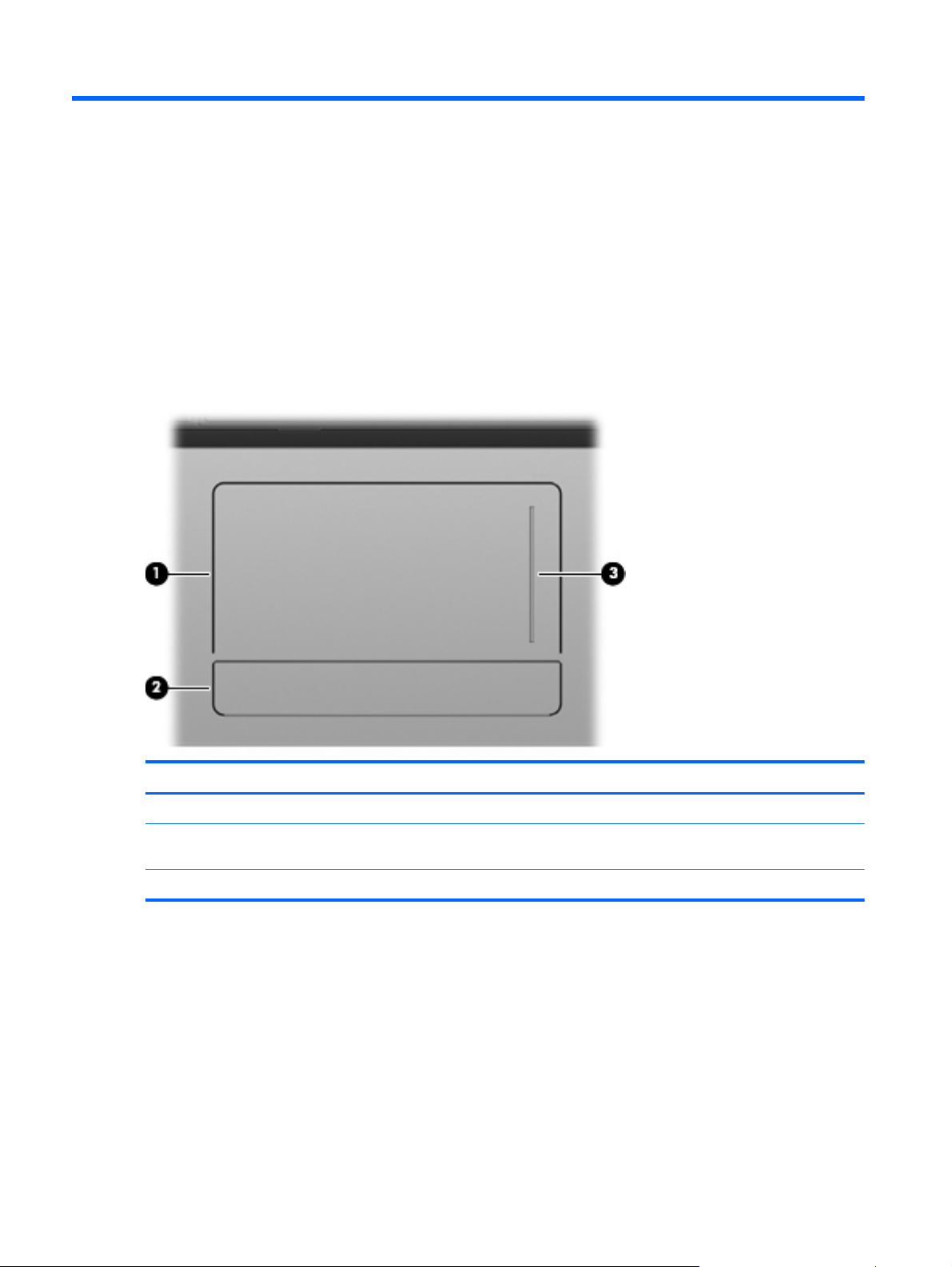
TouchPad
Component Description
(1) TouchPad Moves the pointer and selects or activates items on the screen.
(2) TouchPad button The left and right sides of the single button function like the left
(3) TouchPad scroll zone Scrolls up or down.
8 Chapter 2 External component identification
and right buttons on an external mouse.
Page 19
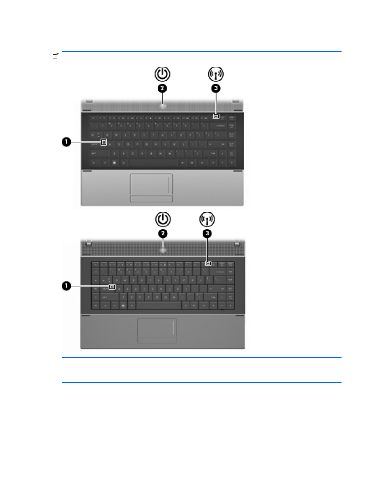
Lights
NOTE: Refer to the illustration that most closely matches your computer.
Component Description
(1) Caps lock light On: Caps lock is on.
Top components 9
Page 20

Component Description
(2) Power light
(3) Wireless light
On: The computer is on.
●
Blinking: The computer is in the Sleep state in Windows 7
●
or Windows Vista, or in Standby in Windows XP.
Off: The computer is off or in Hibernation.
●
White: An integrated wireless device, such as a wireless
●
local area network (WLAN) device is on.
Amber: All wireless devices are off.
●
10 Chapter 2 External component identification
Page 21
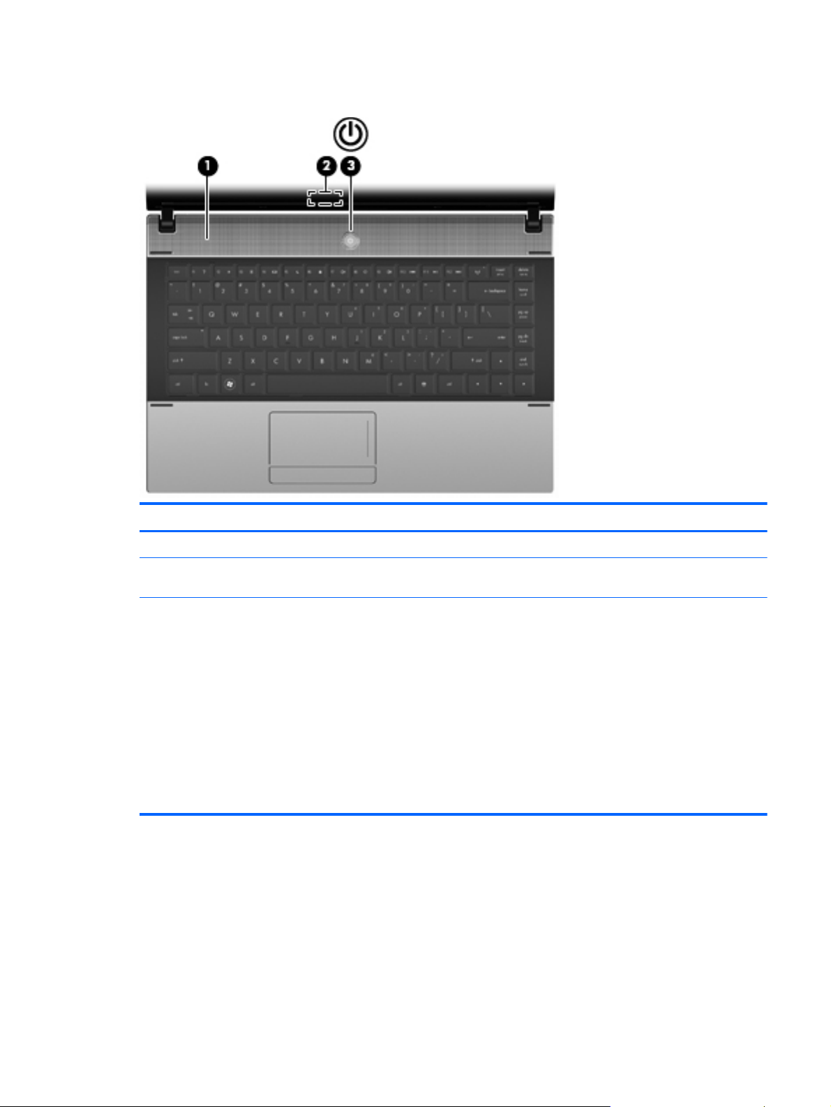
Buttons, switch, and speaker
Component Description
(1) Speaker Produces sound.
(2) Internal display switch Turns off the display if the panel lid is closed while the power is
on.
(3) Power button
When the computer is off, press the button to turn on the
●
computer.
When the computer is on, press the button to shut down the
●
computer.
When the computer is in the Sleep state or in Standby,
●
press the button briefly to exit Sleep or Standby.
When the computer is in Hibernation, press the button
●
briefly to exit Hibernation.
If the computer has stopped responding and Windows shutdown
procedures are ineffective, press and hold the power button for at
least 5 seconds to turn off the computer.
Top components 11
Page 22
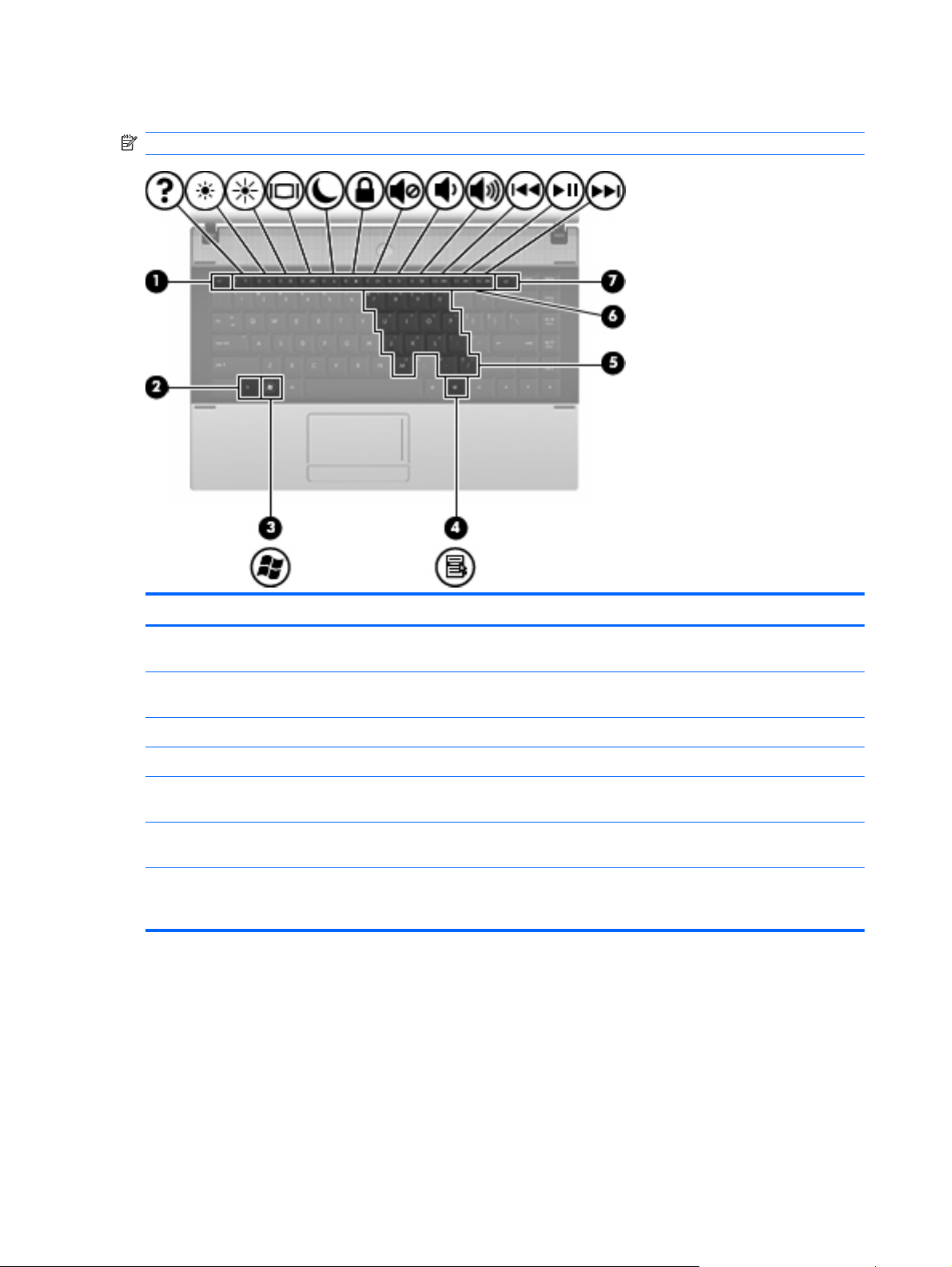
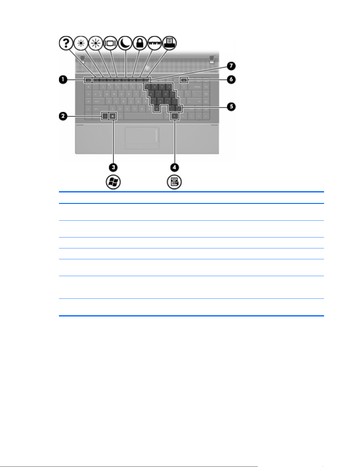
Keys
NOTE: Refer to the illustration and table that most closely matches your computer.
Component Description
(1) esc key Displays system information when pressed in combination with
the fn key.
(2) fn key Executes frequently used system functions when pressed in
combination with a function key or the esc key.
(3) Windows logo key Displays the Windows Start menu.
(4) Windows applications key Displays a shortcut menu for items beneath the cursor.
(5) Embedded numeric keypad keys Can be used like the keys on an external numeric keypad when
pressed in combination with the fn and num lk keys.
(6) Function keys Execute frequently used system functions when pressed in
combination with the fn key.
(7) Wireless key Because the wireless devices are enabled at the factory, use the
wireless key to turn on or turn off the wireless devices
simultaneously.
12 Chapter 2 External component identification
Page 23
Component Description
(1) esc key Displays system information when pressed in combination with
the fn key.
(2) fn key Executes frequently used system functions when pressed in
combination with a function key or the esc key.
(3) Windows logo key Displays the Windows Start menu.
(4) Windows applications key Displays a shortcut menu for items beneath the cursor.
(5) Embedded numeric keypad keys Can be used like the keys on an external numeric keypad when
pressed in combination with the fn and num lk keys.
(6) Wireless key Because the wireless devices are enabled at the factory, use the
wireless key to turn on or turn off the wireless devices
simultaneously.
(7) Function keys Execute frequently used system functions when pressed in
combination with the fn key.
Top components 13
Page 24

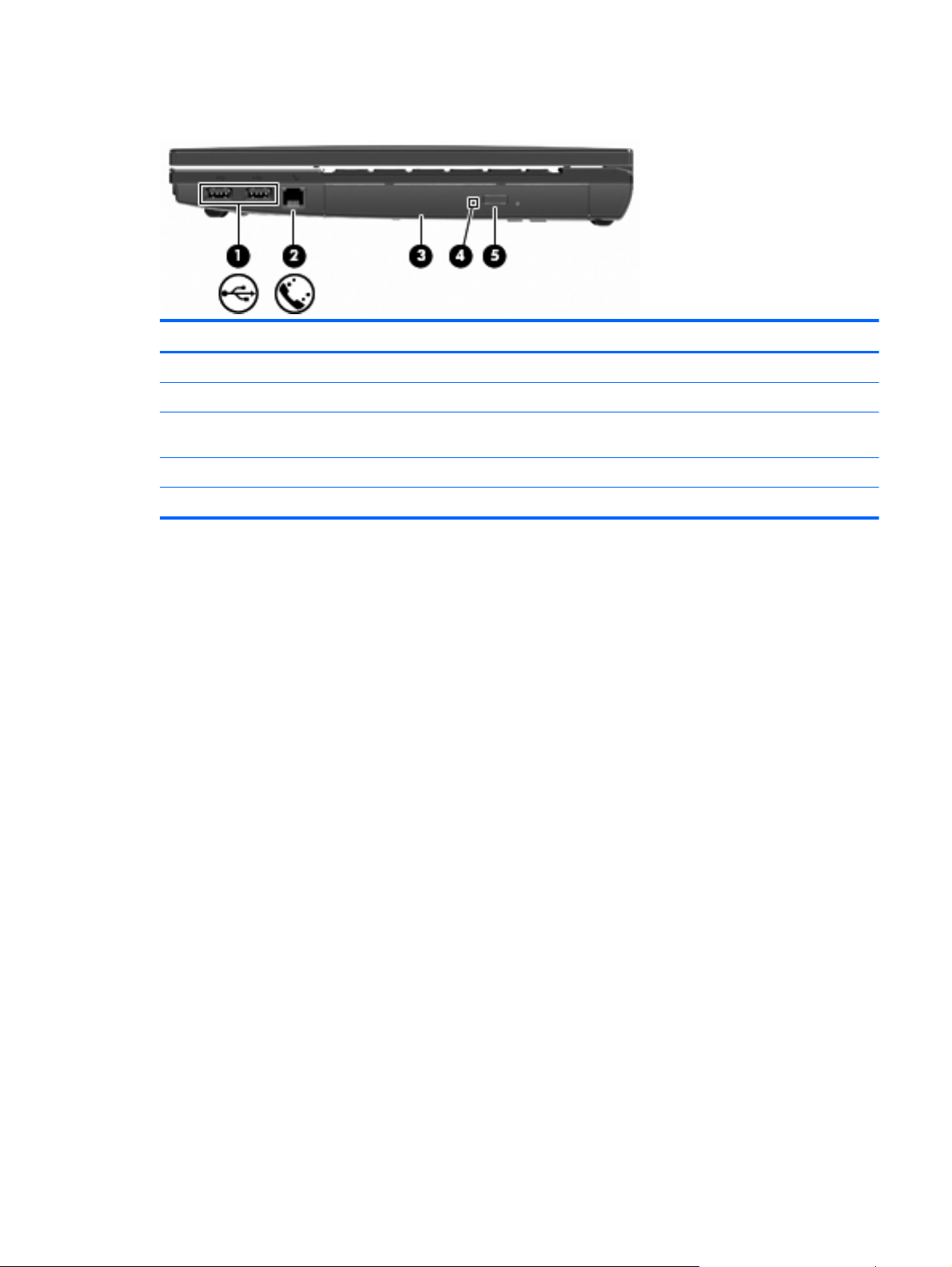
Front components
Component Description
(1) SD Card Reader Supports the following optional digital card formats:
(2) Audio-out (headphone) jack Produces sound when connected to optional powered stereo
MultiMediaCard (MMC)
●
MultiMediaCard 4.2 (MMC Plus, including MMC Plus HC)
●
Secure Digital (SD) Memory Card
●
Secure Digital High Capacity (SDHC) Memory Card
●
Secure Digital High Speed (SDHS) Memory Card
●
speakers, headphones, ear buds, a headset, or television audio.
NOTE: When a device is connected to the headphone jack, the
computer speakers are disabled.
(3) Audio-in (microphone) jack Connects an optional computer headset microphone, stereo
array microphone, or monaural microphone.
14 Chapter 2 External component identification
Page 25
Right-side components
Component Description
(1) USB ports (2) Connect optional USB devices.
(2) RJ-11 (modem) jack (select models only) Connects a modem cable.
(3) Optical drive (select models only) Reads optical discs and, on select models, also writes to optical
(4) Optical drive light (select models only) Blinking: The optical drive is being accessed.
(5) Optical drive button (select models only) Opens optical drive tray.
discs.
Right-side components 15
Page 26
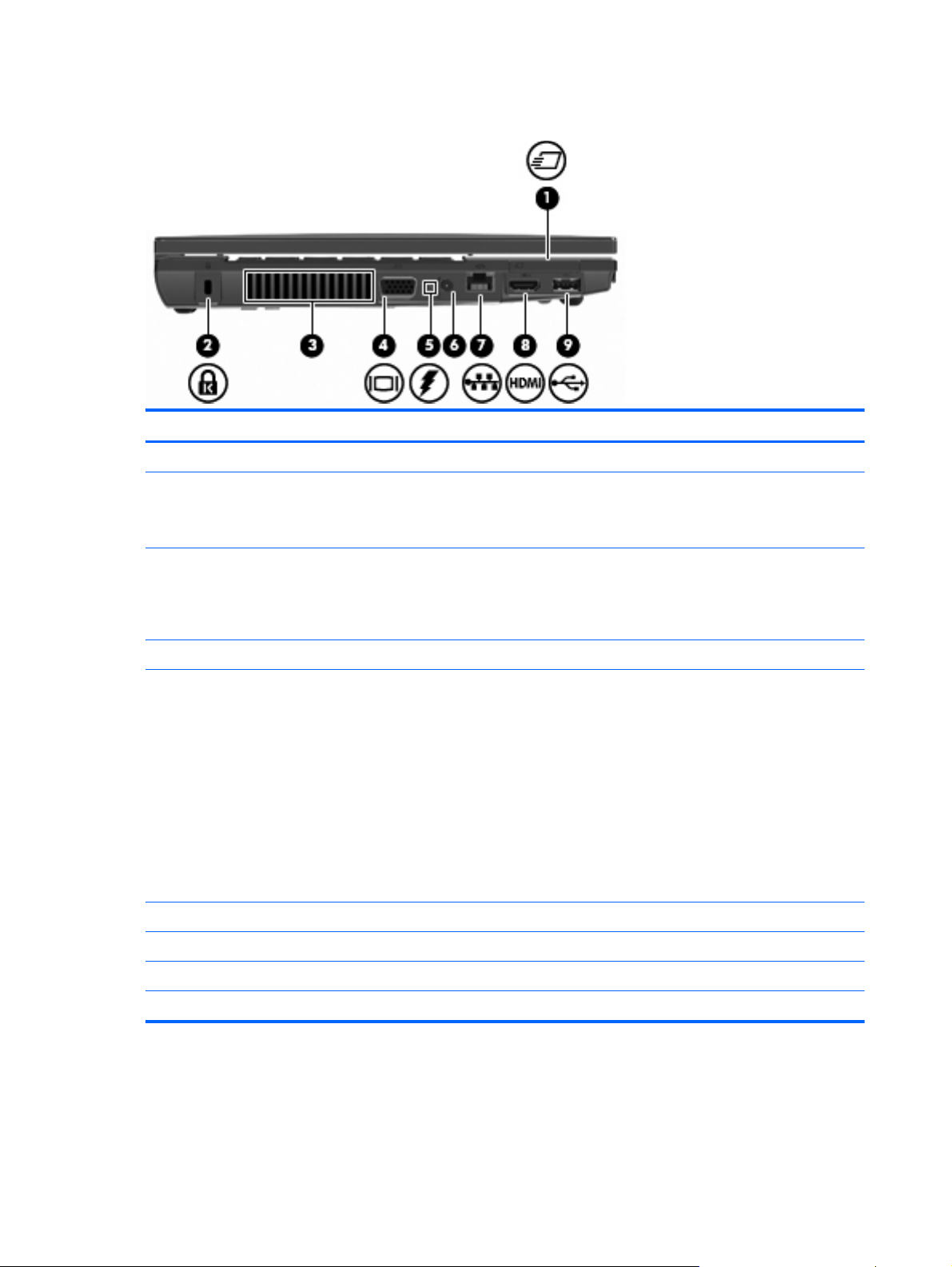
Left-side components
Component Description
(1) ExpressCard slot Supports optional ExpressCards.
(2) Security cable slot Attaches an optional security cable to the computer.
(3) Vent Enables airflow to cool internal components.
NOTE: The security cable is designed to act as a deterrent, but
it may not prevent the computer from being mishandled or stolen.
NOTE: The computer fan starts up automatically to cool internal
components and prevent overheating. It is normal for the internal
fan to cycle on and off during routine operation.
(4) External monitor port Connects an external VGA monitor or projector.
(5) Battery light
(6) Power connector Connects an AC adapter.
(7) RJ-45 (network) jack Connects a network cable.
(8) HDMI port Connects an optional HDMI device.
(9) USB port (1) Connects optional USB devices.
Amber: A battery is charging.
●
Turquoise: A battery is close to full charge capacity.
●
Blinking amber: A battery that is the only available power
●
source has reached a low battery level. When the battery
reaches a critical battery level, the battery light begins
blinking rapidly.
Off: If the computer is plugged into an external power
●
source, the light turns off when all batteries in the computer
are fully charged. If the computer is not plugged into an
external power source the light stays off until the battery
reaches a low battery level.
16 Chapter 2 External component identification
Page 27
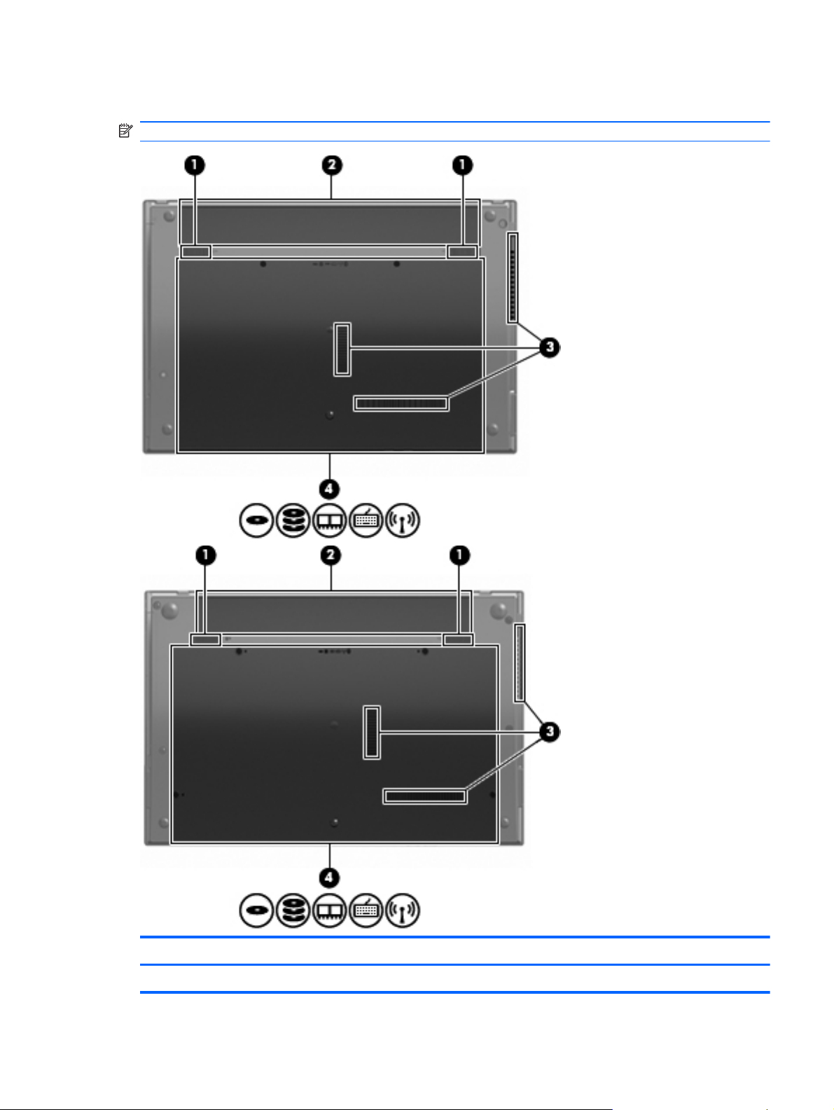
Bottom components
NOTE: Refer to the illustration that most closely matches your computer.
Component Description
(1) Battery release latches (2) Release the battery from the battery bay.
Bottom components 17
Page 28

Component Description
(2) Battery bay Holds the battery.
(3) Vents (3) Enable airflow to cool internal components.
NOTE: The computer fan starts up automatically to cool internal
components and prevent overheating. It is normal for the internal
fan to cycle on and off during routine operation.
(4) Memory module compartment Contains the memory module slots.
WLAN module compartment Contains the wireless LAN module slot.
CAUTION: To prevent an unresponsive system and the display
of a warning message, replace the WLAN module with only a
module authorized for use in the computer by the governmental
agency that regulates wireless devices in your country. If you
replace the module and then receive a warning message,
remove the module to restore computer functionality, and then
contact technical support through Help and Support.
Hard drive bay Holds the hard drive.
18 Chapter 2 External component identification
Page 29
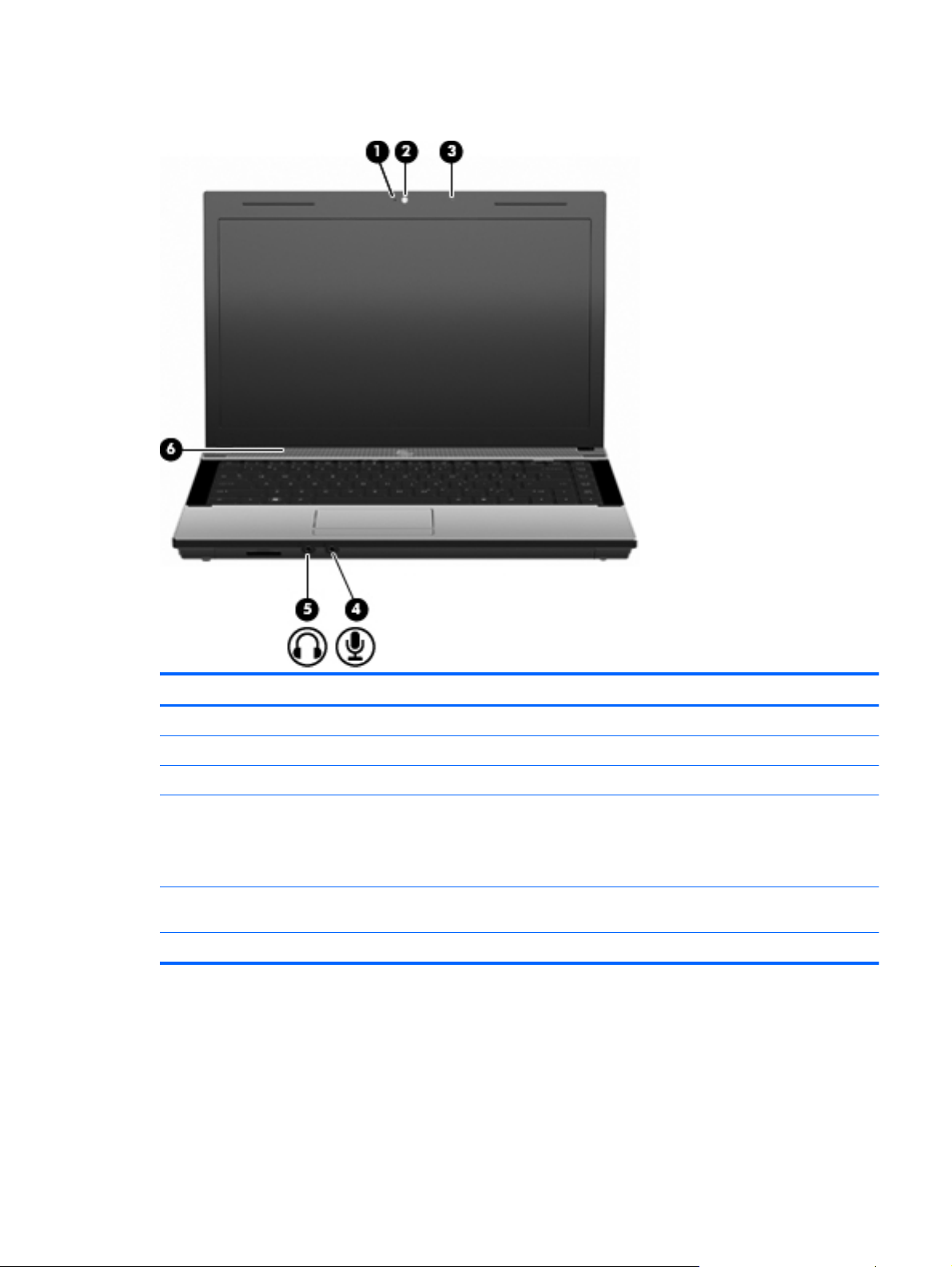
Multimedia components
Component Description
(1) Webcam light (select models only) On: The webcam is in use.
(2) Webcam (select models only) Records video and captures still photographs.
(3) Integrated microphone Records sound.
(4) Audio-out (headphone) jack Produces sound when connected to optional powered stereo
speakers, headphones, ear buds, a headset, or television audio.
NOTE: When a device is connected to the headphone jack, the
computer speakers are disabled.
(5) Audio-in (microphone) jack Connects an optional computer headset microphone, stereo
(6) Speaker Produces sound.
array microphone, or monaural microphone.
Multimedia components 19
Page 30
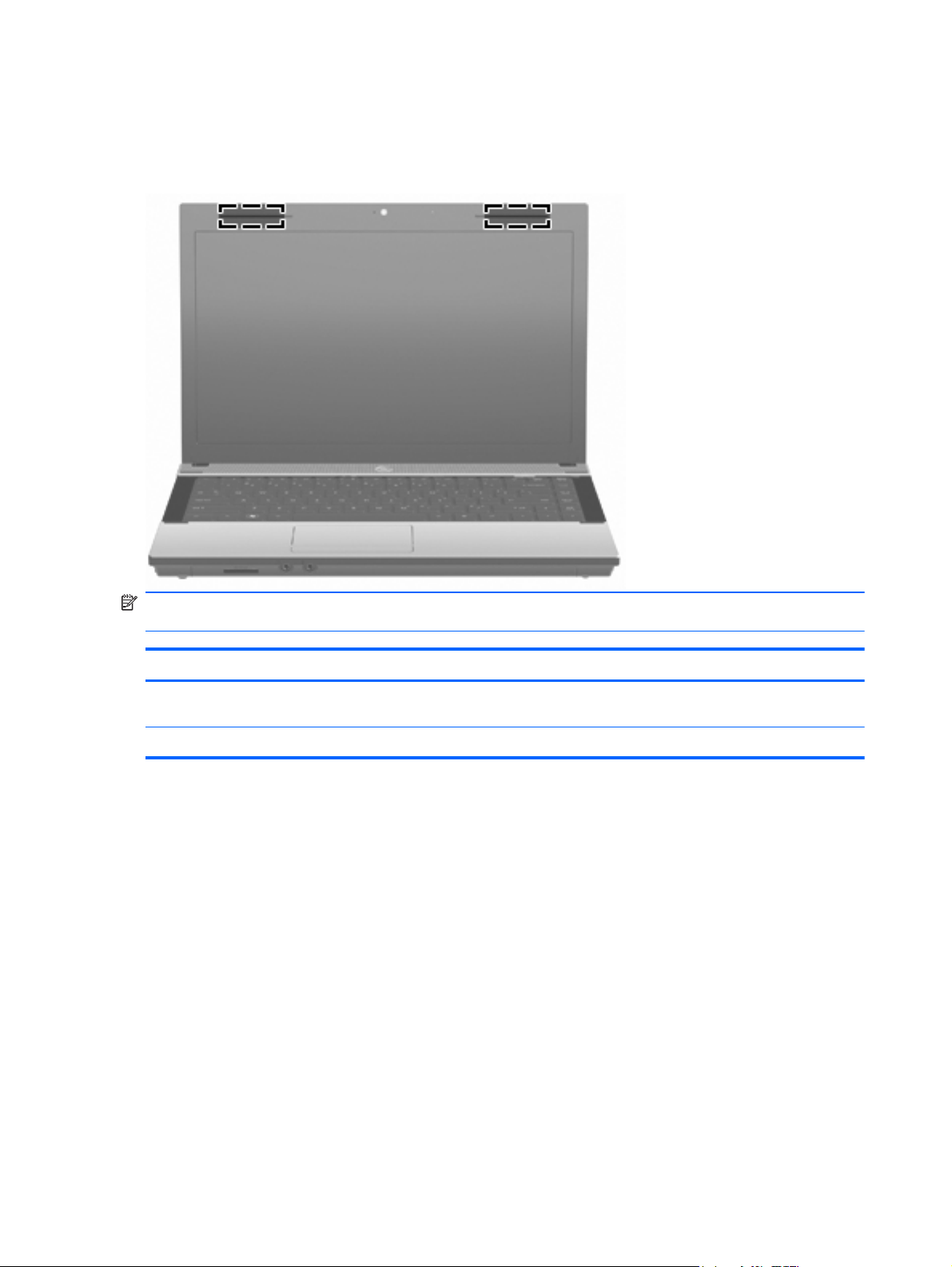
Wireless antennas (select models only)
On select computer models, at least 2 antennas send and receive signals from one or more wireless
devices. These antennas are not visible from the outside of the computer.
NOTE: For optimal transmission, keep the areas immediately around the antennas free from
obstructions.
Component Description
WLAN antennas (2)* Send and receive wireless signals to communicate with wireless
local area networks (WLANs).
*The antennas are not visible from the outside of the computer.
To see wireless regulatory notices, refer to the section of the Regulatory, Safety and Environmental
Notices that applies to your country or region. These notices are located in Help and Support.
20 Chapter 2 External component identification
Page 31

Additional hardware components
Component Description
(1) Power cord* Connects an AC adapter to an AC outlet.
(2) AC adapter Converts AC power to DC power.
(3) Battery* Powers the computer when the computer is not plugged into
*Batteries and power cords vary in appearance by country or region.
external power.
Additional hardware components 21
Page 32

3 Illustrated parts catalog
Service tag
When ordering parts or requesting information, provide the computer serial number and model
description provided on the service tag.
(1) Product name: This is the product name affixed to the front of the computer.
(2) Serial number (s/n): This is an alphanumeric identifier that is unique to each product.
(3) Product number (p/n): This is an alphanumeric identifier that provides specific information about
the hardware components. The product number helps a service technician to determine what
components and parts are needed.
(4) Warranty period: This number describes the duration (in years) of the warranty period for this
computer.
(5) Model description: This is an alphanumeric identifier used to locate documents, drivers, and
support for your computer.
22 Chapter 3 Illustrated parts catalog
Page 33

Computer major components
Computer major components 23
Page 34

Item Description
(1) Display assembly (includes microphone, 2 WLAN antenna transceivers and cables and, on select computer
models, 2 WWAN antenna transceivers and cables)
39.6-cm (15.6-in) HD AntiGlare display assembly for use in computers equipped without
webcam (1366×768 resolution)
39.6-cm (15.6-in) HD AntiGlare display assembly for use in computers equipped with
webcam (1366×768 resolution)
39.6-cm (15.6-in) HD BrightView display assembly for use in computers without webcam
(1366×768 resolution)
39.6-cm (15.6-in) HD BrightView display assembly for use in computers with webcam
(1366×768 resolution)
35.6-cm (14.0-in) HD AntiGlare display assembly for use in computers without webcam
(1366×768 resolution)
35.6-cm (14.0-in) HD AntiGlare display assembly for use in computers equipped with
webcam (1366×768 resolution)
35.6-cm (14.0-in) HD BrightView display assembly for use in computers without webcam
(1366×768 resolution)
35.6-cm (14.0-in) HD BrightView display assembly for use in computers equipped with
webcam (1366×768 resolution)
33.8-cm (13.3-in) HD AntiGlare display assembly for use in computers with WLAN but
without webcam (1366×768 resolution)
33.8-cm (13.3-in) HD AntiGlare display assembly for use in computers with WLAN and
webcam (1366×768 resolution)
33.8-cm (13.3-in) HD BrightView display assembly for use in computers with WLAN but
without webcam (1366×768 resolution)
605801-001
605802-001
605803-001
605804-001
605805-001
605806-001
605807-001
605808-001
605809-001
605810-001
605811-001
33.8-cm (13.3-in) HD BrightView display assembly for use in computers with WLAN and
webcam (1366×768 resolution)
33.8-cm (13.3-in) HD AntiGlare display assembly for use in computers with WLAN but
without webcam (1366×768 resolution), red
33.8-cm (13.3-in) HD AntiGlare display assembly for use in computers with WLAN and
webcam (1366×768 resolution), red
33.8-cm (13.3-in) HD BrightView display assembly for use in computers with WLAN but
without webcam (1366×768 resolution), red
33.8-cm (13.3-in) HD BrightView display assembly for use in computers with WLAN and
webcam (1366×768 resolution), red
(2) Keyboard
NOTE: For a detailed list of available keyboards, see
For use in 33.8-cm (13.3-in) and 35.6-cm (14.0-in) computers 605813-xxx
For use in 39.6-cm (15.6-in) computers 605814-xxx
(3) Palm rest (includes TouchPad, TouchPad board, and 2 ribbon cables)
For use in Compaq 33.8-cm (13.3-in) computers 605779-001
For use in Compaq 33.8-cm (13.3-in) computers, red 616602-001
For use in HP 35.6-cm (14.0-in) computers 605780-001
Sequential part number listing on page 35.
605812-001
616597-001
616598-001
616599-001
616600-001
24 Chapter 3 Illustrated parts catalog
Page 35

Item Description
For use in HP 39.6-cm (15.6-in) computers 605782-001
(4) TouchPad board 605795-001
(5) Top cover
Top cover for Compaq 33.8-cm (13.3-in) computers 605774-001
Top cover for Compaq 33.8-cm (13.3-in) computers, red 616601-001
Top cover for HP 35.6-cm (14.0-in) computers 605775-001
Top cover for HP 39.6-cm (15.6-in) computers 605777-001
(6) Heat sink
For use in computers with UMA graphics subsystems 611804-001
For use in computers with discrete graphics subsystems, NB 611805-001
For use in computers with discrete graphics subsystems, CPU 615355-001
(7) Fan
For use in 39.6-cm (15.6-in) computers 605791-001
For use in 35.6-cm (14.0-in) and 33.8-cm (13.3-in) computers 605787-001
(8) Power switch board 605794-001
(9) System board (includes RTC battery and replacement thermal material)
System board with discrete graphics and RTC battery with RS880M chipset 611802-001
System board with UMA graphics and RTC battery with RS880M chipset 611803-001
(10) Modem module
NOTE: The modem module spare part kit does not include a modem module cable. The
modem module cable is included in the Cable Kit , spare part number 599807-001. See
Cables on page 31 for more Cable Kit spare part information.
For use in all countries and regions except Australia and New Zealand 510100-001
For use only in Australia and New Zealand 510100-011
(11) RTC battery 449137-001
(12) Hard drive extender for use in 39.6-cm (15.6-in) computers 605798-001
(13) Optical drive extender
For use in 39.6-cm (15.6-in) computers 605799-001
For use in 35.6-cm (14.0-in) computers 605800-001
(14) USB board with cable 605796-001
USB board for use on system boards with UMA graphics subsystem 622615-001
Computer major components 25
Page 36

Item Description
(15) Bluetooth module
HP Integrated module with Bluetooth 2.1 wireless technology For use in Andorra,
Argentina, Australia, Austria, Bangladesh, Belarus, Belgium, Bermuda, Brazil, Brunei,
Bulgaria, Canada, Cayman Islands, Chile, China, Croatia, Cyprus, Czech Republic,
Denmark, Egypt, El Salvador, Estonia, Finland, France, Germany, Greece, French Guiana,
Guadeloupe, Guam, Hong Kong, Hungary, Iceland, India, Indonesia, Ireland, Israel, Italy,
Japan, Jordan, South Korea, Latvia, Puerto Rico, Liechtenstein, Lithuania, Luxembourg,
Malaysia, Malta, Martinique, Mexico, Morocco, Netherlands, New Zealand, Norway,
Pakistan, Panama, Peru, Philippines, Poland, Portugal, Romania, Russia, Saudi Arabia,
Singapore, Slovakia, Slovenia, South Africa, Spain, Sri Lanka, Sweden, Switzerland,
Taiwan, Thailand, Tunisia, Turkey, Ukraine, United Arab Emirates, the United Kingdom, the
United States, Venezuela, Virgin Islands
(16) AMD Processor (includes replacement thermal material) (not illustrated)
AMD Turion™ II Dual-Core P520 2.3-GHz with 2-MB L2 cache 594173-001
AMD Athlon™ II Dual-Core P320 2.1–GHz with 2-MB L2 cache 594165-001
AMD Phenom II Champlain P820 25W 594167-001
AMD V-Series Single-Core V120 2.2-GHz with 2-MB L2 cache 594171-001
(17) Speaker 605792-001
(18) Audio board 620608-001
Audio board for use on system boards with UMA graphics subsystem 622614-001
(19) Base enclosure
537921-001
For use in 33.8-cm (13.3-in) computers 622191-001
For use in 35.6-cm (14.0-in) computers 620609-001
For use in 39.6-cm (15.6-in) computers 622192-001
(20) Battery
9-cell, 93-Wh, 2.8-Ah 593573-001
6-cell, 47-Wh, 2.2-Ah 593572-001
(21) Memory module
2-GB (PC3-10600, 1333-MHz, DDR3) 598856-001
1-GB (PC3-10600, 1333-MHz, DDR3) 598859-001
(22) WLAN module
Broadcom 4313AGN 802.11a/b/g/draft-n WiFi Adapter 593836-001
Broadcom 4312G 802.11b/g WiFi adapters:
For use in Antigua and Barbuda, Barbados, Belize, Canada, the Cayman Islands,
●
Guam, Puerto Rico, Trinidad and Tobago, the U.S. Virgin Islands, and the United
States
504593-003
26 Chapter 3 Illustrated parts catalog
Page 37

Item Description
Atheros 9285G 802.11b/g/n WiFi Adapter for use in all countries and regions 605560-005
Realtek RTL8191SE 802.11b/g/n WiFi Adapter for use in all countries and regions 593533-001
For use in Afghanistan, Albania, Algeria, Andorra, Angola, Antigua and Barbuda,
●
Argentina, Armenia, Aruba, Australia, Austria, Azerbaijan, the Bahamas, Bahrain,
Bangladesh, Barbados, Belarus, Belgium, Belize, Benin, Bermuda, Bhutan, Bolivia,
Bosnia and Herzegovina, Botswana, Brazil, the British Virgin Islands, Brunei, Bulgaria,
Burkina Faso, Burundi, Cameroon, Cape Verde, the Central African Republic, Chad,
Chile, the People's Republic of China, Colombia, Comoros, the Congo, Costa Rica,
Croatia, Cyprus, the Czech Republic, Denmark, Djibouti, Dominica, the Dominican
Republic, East Timor, Ecuador, Egypt, El Salvador, Equitorial Guinea, Eritrea, Estonia,
Ethiopia, Fiji, Finland, France, French Guiana, Gabon, Gambia, Georgia, Germany,
Ghana, Gibraltar, Greece, Grenada, Guadeloupe, Guatemala, Guinea, Guinea-Bissau,
Guyana, Haiti, Honduras, Hong Kong, Hungary, Iceland, India, Ireland, Israel, Italy, the
Ivory Coast, Jamaica, Jordan, Kazakhstan, Kenya, Kiribati, Kyrgyzstan, Laos, Latvia,
Lebanon, Lesotho, Liberia, Liechtenstein, Lithuania, Luxembourg, Macedonia,
Madagascar, Malawi, Malaysia, the Maldives, Mali, Malta, the Marshall Islands,
Martinique, Mauritania, Mauritius, Mexico, Micronesia, Monaco, Mongolia, Montenegro,
Morocco, Mozambique, Namibia, Nauru, Nepal, the Nether Antilles, the Netherlands,
New Zealand, Nicaragua, Niger, Nigeria, Norway, Oman, Pakistan, Palau, Panama,
Papua New Guinea, Paraguay, Peru, the Philippines, Poland, Portugal, the Republic of
Moldova, Romania, Russia, Rwanda, Samoa, San Marino, Sao Tome and Principe,
Saudi Arabia, Senegal, Serbia, the Seychelles, Sierra Leone, Singapore, Slovakia,
Slovenia, the Solomon Islands, Somalia, South Africa, South Korea, Spain, Sri Lanka,
St. Kitts and Nevis, St. Lucia, St. Vincent and the Grenadines, Suriname, Swaziland,
Sweden, Switzerland, Taiwan, Tajikistan, Tanzania, Togo, Tonga, Trinidad and
Tobago, Tunisia, Turkey, Turkmenistan, Tuvalu, Uganda, Ukraine, the United Arab
Emirates, the United Kingdom, Uruguay, Uzbekistan, Vanuatu, Venezuela, Vietnam,
Yemen, Zaire, Zambia, and Zimbabwe
504593-004
(23) Hard drive (includes hard drive bracket)
500-GB, 7200-rpm 608139-001
500-GB, 7200-rpm for use in 39.6-cm (15.6-in) computers 611029-001
500-GB, 5400-rpm 614958-001
500-GB, 5400-rpm for use in 39.6-cm (15.6-in) computers 614956-001
320-GB, 7200-rpm 608138-001
320-GB, 7200-rpm for use in 39.6-cm (15.6-in) computers 611028-001
320-GB, 5400-rpm 614957-001
320-GB, 5400-rpm for use in 39.6-cm (15.6-in) computers 614955-001
250-GB, 7200-rpm 608137-001
250-GB, 7200-rpm for use in 39.6-cm (15.6-in) computers 611027-001
250-GB, 5400-rpm 493994-001
250-GB, 5400-rpm for use in 39.6-cm (15.6-in) computers 614523-001
160-GB, 7200-rpm 455954-001
160-GB, 7200-rpm for use in 39.6-cm (15.6-in) computers 614522-001
160-GB, 5400-rpm 615040-001
160-GB, 5400-rpm for use in 39.6-cm (15.6-in) computers 615844-001
(24) Optical drive (includes bezel)
Computer major components 27
Page 38

Item Description
DVD-ROM Drive 608141-001
DVD±RW Double-Layer Drive with LightScribe 608140-001
(25) Access door
For use in 33.8-cm (13.3-in) and 35.6-cm (14.0-in) computers 605784-001
For use in 39.6-cm (15.6-in) computers 605785-001
28 Chapter 3 Illustrated parts catalog
Page 39
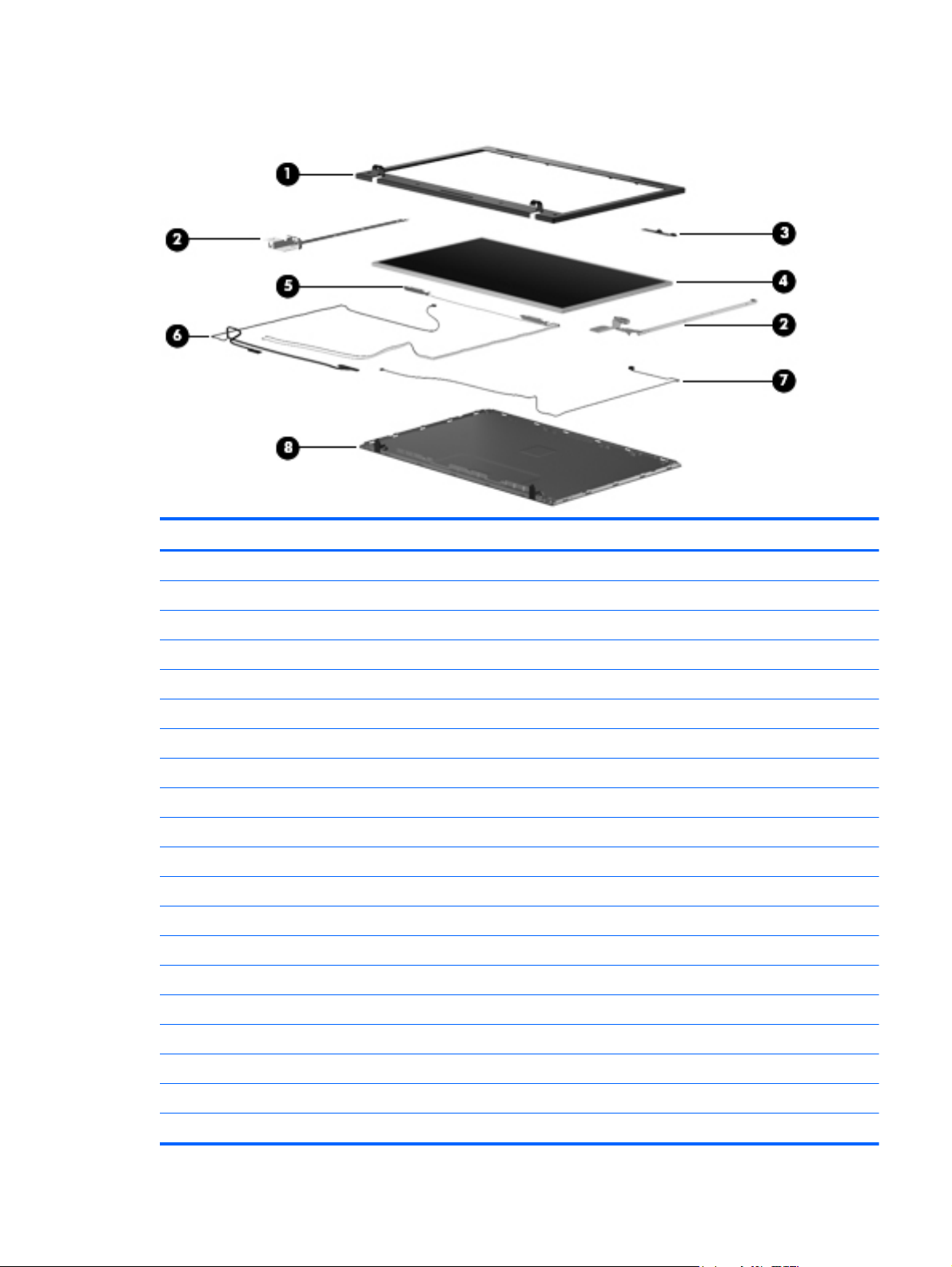
Display assembly components
Item Description Spare part number
(1) Display bezel
Compaq 33.8-cm (13.3-in) LCD bezel without webcam 605751-001
Compaq 33.8-cm (13.3-in) LCD bezel with webcam 605752-001
HP 35.6-cm (14.0-in) LCD bezel without webcam 605753-001
HP 35.6-cm (14.0-in) LCD bezel with webcam 605754-001
HP 39.6-cm (15.6-in) LCD bezel without webcam 605757-001
HP 39.6-cm (15.6-in) LCD bezel with webcam 605758-001
(2) Display Hinge Kit
Hinge Kit for 35.6-cm (14.0-in) and 33.8-cm (13.3-in) computers 605768-001
Hinge Kit for 39.6-cm (15.6-in) computers 605769-001
(3) Webcam module 611026-001
(4) Display panel
Display panel AntiGlare without webcam for use in 39.6-cm (15.6-in) computers 605801-001
Display panel AntiGlare with webcam for use in 39.6-cm (15.6-in) computers 605802-001
Display panel BrightView without webcam for use in 39.6-cm (15.6-in) computers 605803-001
Display panel BrightView with webcam for use in 39.6-cm (15.6-in) computers 605804-001
Display panel AntiGlare without webcam for use in 35.6-cm (14-in) computers 605805-001
Display panel AntiGlare with webcam for use in 35.6-cm (14-in) computers 605806-001
Display panel BrightView without webcam for use in 35.6-cm (14-in) computers 605807-001
Display panel BrightView with webcam for use in 35.6-cm (14-in) computers 605808-001
Display assembly components 29
Page 40

Item Description Spare part number
Display panel AntiGlare without webcam for use in 33.8-cm (13.3-in) computers 605809-001
Display panel AntiGlare with webcam for use in 33.8-cm (13.3-in) computers 605810-001
Display panel BrightView without webcam for use in 33.8-cm (13.3-in) computers 605811-001
Display panel BrightView with webcam for use in 33.8-cm (13.3-in) computers 605812-001
Display panel AntiGlare without webcam for use in 33.8-cm (13.3-in) computers, red 616597-001
Display panel AntiGlare with webcam for use in 33.8-cm (13.3-in) computers, red 616598-001
Display panel BrightView without webcam for use in 33.8-cm (13.3-in) computers, red 616599-001
Display panel BrightView with webcam for use in 33.8-cm (13.3-in) computers, red 616600-001
(5) WLAN transceiver cable spared with display
assembly
(6) LCD cable
LCD cable with webcam 605767-001
LCD cable without webcam 605766-001
(7) Microphone cable
(8) Display enclosure
For use in Compaq 33.8-cm (13.3-in) computers 605761-001
For use in Compaq 33.8-cm (13.3-in) computers, red 616596-001
For use in HP 35.6-cm (14.0-in) computers 605762-001
For use in HP 39.6-cm (15.6-in) computers 605764-001
Plastics Kit
30 Chapter 3 Illustrated parts catalog
Page 41

Item Description Spare part number
Plastics Kit: 605786-001
(1) ExpressCard slot bezel
(2) Optical drive bezel
Cables
Item Description Spare part number
Cable Kit , includes: 605793-001
(1) Bluetooth cable
(2) RJ-11 cable
(3) Main battery connector
Cables 31
Page 42

Item Description Spare part number
(1) WLAN transceiver with cable spared with display
assembly
(2) Microphone cable spared with display
assembly
(3) LCD Cable Kit
LCD Cable without webcam ( not shown) 605766-001
LCD Cable with webcam cable 605767-001
(4) USB cable 605796-001
32 Chapter 3 Illustrated parts catalog
Page 43
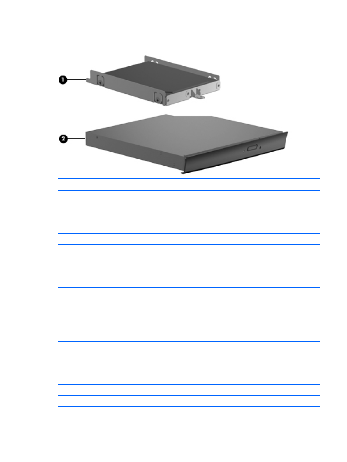
Mass storage devices
Item Description Spare part number
(1) Hard drive (includes bracket)
500-GB, 7200-rpm 608139-001
500-GB, 7200-rpm for use in 39.6-cm (15.6-in) computers 611029-001
500-GB, 5400-rpm 614958–001
500-GB, 5400-rpm for use in 39.6-cm (15.6-in) computers 614956-001
320-GB, 7200-rpm 608138-001
320-GB, 7200-rpm for use in 39.6-cm (15.6-in) computers 611028-001
320-GB, 5400-rpm 614957-001
320-GB, 5400-rpm for use in 39.6-cm (15.6-in) computers 614955-001
250-GB, 7200-rpm 608137-001
250-GB, 7200-rpm for use in 39.6-cm (15.6-in) computers 611027-001
250-GB, 5400-rpm 493994-001
250-GB, 5400-rpm for use in 39.6-cm (15.6-in) computers 614523-001
160-GB, 7200-rpm 455954-001
160-GB, 7200-rpm for use in 39.6-cm (15.6-in) computers 614522-001
160-GB, 5400-rpm 615040-001
160-GB 5400-rpm for use in 39.6-cm (15.6-in) computers 615844-001
(2) Optical drive (includes bezel)
DVD±RW Double-Layer Drive with LightScribe 608140-001
DVD-ROM Drive 608141-001
Mass storage devices 33
Page 44

Miscellaneous parts
Description Spare part number
AC adapters
65-W AC adapter for use with computers with UMA graphics 613149-001
90-W AC adapter for use with computers with discrete graphics 613150-001
Power cords
For use in Argentina 490371-D01
For use in Brazil 490371-201
For use in Denmark 490371-081
For use in Europe, the Middle East, and Africa 490371-021
For use in Israel 490371-BB1
For use in Italy 490371-061
For use in South Africa 490371-AR1
For use in Switzerland 490371-111
For use in the United Kingdom 490371-031
For use in the United States 490371-001
Screw Kit, includes:
(15) Torx 2.5×6.0 screws
●
(15) Phillips 2.5×4.5 screws
●
(15) Phillips 2.5×4.5 screws
●
(15) Phillips 2.5×4.5 screws
●
(15) Phillips 2.0×3.0 screws
●
(15) Phillips 3.0×4.5 screws
●
Rubber Kit (contains: 10 top bumper strips, 20 bottom case hinge bumpers, 10 rubber feet, 10
middle body bumpers, 10 RJ-11 bumpers, 10 bottom case bumpers)
For use in 33.8-cm (13.3-in) and 35.6-cm (14.0-in) computers 605789-001
For use in 39.6-cm (15.6-in) computers 608931-001
605790-001
34 Chapter 3 Illustrated parts catalog
Page 45

Sequential part number listing
Spare part
number
449137-001 RTC battery
455954-001 160-GB, 7200-rpm hard drive for use in computers with 35.6-cm (14-in) or 33.8-cm (13.3-in) displays
490371-001 Power cord for use in the United States
490371-021 Power cord for use in Europe, the Middle East, and Africa
490371-031 Power cord for use in the United Kingdom
490371-061 Power cord for use in Italy
490371-081 Power cord for use in Denmark
490371-111 Power cord for use in Switzerland
490371-201 Power cord for use in Brazil
490371-AR1 Power cord for use in South Africa
490371-BB1 Power cord for use in Israel
490371-D01 Power cord for use in Argentina
493994-001 250-GB, 5400-rpm hard drive for use in computers with 35.6-cm (14-in) or 33.8-cm (13.3-in) displays
504593-003 Broadcom BCM4312 802.11b/g WLAN module for use in Antigua and Barbuda, Barbados, Belize, Canada,
Description
the Cayman Islands, Guam, Puerto Rico, Trinidad and Tobago, the U.S. Virgin Islands, and the United
States
504593-004 Broadcom 4312 802.11b/g WLAN module for use in Afghanistan, Albania, Algeria, Andorra, Angola,
Antigua and Barbuda, Argentina, Armenia, Aruba, Australia, Austria, Azerbaijan, the Bahamas, Bahrain,
Bangladesh, Barbados, Belarus, Belgium, Belize, Benin, Bermuda, Bhutan, Bolivia, Bosnia and
Herzegovina, Botswana, Brazil, the British Virgin Islands, Brunei, Bulgaria, Burkina Faso, Burundi,
Cameroon, Cape Verde, the Central African Republic, Chad, Chile, the People's Republic of China,
Colombia, Comoros, the Congo, Costa Rica, Croatia, Cyprus, the Czech Republic, Denmark, Djibouti,
Dominica, the Dominican Republic, East Timor, Ecuador, Egypt, El Salvador, Equitorial Guinea, Eritrea,
Estonia, Ethiopia, Fiji, Finland, France, French Guiana, Gabon, Gambia, Georgia, Germany, Ghana,
Gibraltar, Greece, Grenada, Guadeloupe, Guatemala, Guinea, Guinea-Bissau, Guyana, Haiti, Honduras,
Hong Kong, Hungary, Iceland, India, Ireland, Israel, Italy, the Ivory Coast, Jamaica, Jordan, Kazakhstan,
Kenya, Kiribati, Kyrgyzstan, Laos, Latvia, Lebanon, Lesotho, Liberia, Liechtenstein, Lithuania, Luxembourg,
Macedonia, Madagascar, Malawi, Malaysia, the Maldives, Mali, Malta, the Marshall Islands, Martinique,
Mauritania, Mauritius, Mexico, Micronesia, Monaco, Mongolia, Montenegro, Morocco, Mozambique,
Namibia, Nauru, Nepal, the Nether Antilles, the Netherlands, New Zealand, Nicaragua, Niger, Nigeria,
Norway, Oman, Pakistan, Palau, Panama, Papua New Guinea, Paraguay, Peru, the Philippines, Poland,
Portugal, the Republic of Moldova, Romania, Russia, Rwanda, Samoa, San Marino, Sao Tome and
Principe, Saudi Arabia, Senegal, Serbia, the Seychelles, Sierra Leone, Singapore, Slovakia, Slovenia, the
Solomon Islands, Somalia, South Africa, South Korea, Spain, Sri Lanka, St. Kitts and Nevis, St. Lucia, St.
Vincent and the Grenadines, Suriname, Swaziland, Sweden, Switzerland, Taiwan, Tajikistan, Tanzania,
Togo, Tonga, Trinidad and Tobago, Tunisia, Turkey, Turkmenistan, Tuvalu, Uganda, Ukraine, the United
Arab Emirates, the United Kingdom, Uruguay, Uzbekistan, Vanuatu, Venezuela, Vietnam, Yemen, Zaire,
Zambia, and Zimbabwe
510100-001 Modem module for use in all countries and regions except Australia and New Zealand
510100-011 Modem module for use in Australia and New Zealand
537921-001 Bluetooth module with Bluetooth 2.1 wireless technology
593533-001 Realtek RTL8191SE 802.11b/g/n WiFi Adapter
593572-001 Battery, 6-cell, 47 Wh, 2.2 Ah for use in computers with 15.6-in displays
Sequential part number listing 35
Page 46

Spare part
number
593573-001 Battery, 9-cell, 93 Wh, 2.8 Ah for use in computers with 15.6-in displays
593836-001 Broadcom 4313AGN 802.11a/b/g/draft-n WiFi Adapter
594165-001 AMD Athlon™ II Dual-Core P320 2.1-GHz processor with 2-MB L2 cache
594167-001 AMD Phenom II Champlain P820 25W processor
594171-001 AMD V-Series Single-Core V120 2.2-GHz processor with 2-MB L2 cache
594173-001 AMD Turion II Dual-Core P520 2.3-GHz processor with 2-MB L2 cache
598856-001 2-GB memory (PC3-10600, 1333-MHz, DDR3)
598859-001 1-GB memory (PC3-10600, 1333-MHz, DDR3
605560-005 Atheros 9285G 802.11b/g/n WiFi Adapter
605751-001 Compaq 33.8-cm (13.3-in) LCD bezel without webcam
605752-001 Compaq 33.8-cm (13.3-in) LCD bezel with webcam
605753-001 HP 35.6-cm (14.0-in) LCD bezel without webcam
605754-001 HP 35.6-cm (14.0-in) LCD bezel with webcam
605757-001 HP 39.6-cm (15.6-in) LCD bezel without webcam
605758-001 HP 39.6-cm (15.6-in) LCD bezel with webcam
Description
605761-001 Compaq 33.8-cm (13.3-in) display enclosure
605762-001 HP 35.6-cm (14.0-in) display enclosure
605764-001 HP 39.6-cm (15.6-in) display enclosure
605766-001 LCD cable without webcam
605767-001 LCD cable with webcam
605768-001 Hinge Kit for 35.6-cm (14.0-in) and 33.8-cm (13.3-in) computers
605769-001 Hinge Kit for 39.6-cm (15.6-in) computers
605774-001 Top cover for Compaq 33.8-cm (13.3-in) computers
605775-001 Top cover for HP 35.6-cm (14.0-in) computers
605777-001 Top cover for HP 39.6-cm (15.6-in) computers
605779-001 Palm rest with TouchPad for Compaq 33.8-cm (13.3-in) computers (includes TouchPad board and cable)
605780-001 Palm rest with TouchPad for HP 35.6-cm (14.0-in) computers (includes TouchPad board and cable)
605782-001 Palm rest with TouchPad for HP 39.6-cm (15.6-in) computers (includes TouchPad board and cable)
605784-001 Service door for 33.8-cm (13.3-in) and 35.6-cm (14.0-in) computers
605785-001 Service door for 39.6-cm (15.6-in) computers
605786-001 Plastics Kit
605787-001 Fan for use in 33.8-cm (13.3-in) and 35.6-cm (14.0-in) computers
605789-001 Rubber Kit for 33.8-cm (13.3-in) and 35.6-cm (14.0-in) computers
605790-001 Screw Kit
36 Chapter 3 Illustrated parts catalog
Page 47

Spare part
number
605791-001 Fan for use in 39.6-cm (15.6-in) computers
605792-001 Speaker
605793-001 Cable Kit
605794-001 Power switch board
605795-001 TouchPad board
605796-001 USB board
605798-001 Hard drive extender for use in 39.6-cm (15.6-in) computers
605799-001 Optical drive extender for 39.6-cm (15.6-in) computers
605800-001 Optical drive extender for 35.6-cm (14.0-in) computers
605801-001 39.6-cm (15.6-in) HD AntiGlare display assembly for use in computers equipped without webcam
605802-001 39.6-cm (15.6-in) HD AntiGlare display assembly for use in computers equipped with webcam (1366×768
605803-001 39.6-cm (15.6-in) HD BrightView display assembly for use in computers without webcam (1366×768
605804-001 39.6-cm (15.6-in) HD BrightView display assembly for use in computers with webcam (1366×768
Description
(1366×768 resolution)
resolution)
resolution)
resolution)
605805-001 35.6-cm (14.0-in) HD AntiGlare display assembly for use in computers without webcam (1366×768
resolution)
605806-001 35.6-cm (14.0-in) HD AntiGlare display assembly for use in computers equipped with webcam (1366×768
resolution)
605807-001 35.6-cm (14.0-in) HD BrightView display assembly for use in computers without webcam (1366×768
resolution)
605808-001 35.6-cm (14.0-in) HD BrightView display assembly for use in computers equipped with webcam (1366×768
resolution)
605809-001 33.8-cm (13.3-in) HD AntiGlare display assembly for use in computers with WLAN but without webcam
(1366×768 resolution)
605810-001 33.8-cm (13.3-in) HD AntiGlare display assembly for use in computers with WLAN and webcam (1366×768
resolution)
605811-001 33.8-cm (13.3-in) HD BrightView display assembly for use in computers with WLAN but without webcam
(1366×768 resolution)
605812-001 33.8-cm (13.3-in) HD BrightView display assembly for use in computers with WLAN and webcam
(1366×768 resolution)
605813-001 Keyboard for 35.6-cm (14.0-in) and 33.8-cm (13.3-in) computers for use in the United States
605813-031 Keyboard for 35.6-cm (14.0-in) and 33.8-cm (13.3-in) computers for use in the United Kingdom
605813-041 Keyboard for 35.6-cm (14.0-in) and 33.8-cm (13.3-in) computers for use in Germany
605813-051 Keyboard for 35.6-cm (14.0-in) and 33.8-cm (13.3-in) computers for use in France
605813-061 Keyboard for 35.6-cm (14.0-in) and 33.8-cm (13.3-in) computers for use in Italy
605813-071 Keyboard for 35.6-cm (14.0-in) and 33.8-cm (13.3-in) computers for use in Spain
Sequential part number listing 37
Page 48

Spare part
number
605813-081 Keyboard for 35.6-cm (14.0-in) and 33.8-cm (13.3-in) computers for use in Denmark
605813-091 Keyboard for 35.6-cm (14.0-in) and 33.8-cm (13.3-in) computers for use in Norway
605813-121 Keyboard for 35.6-cm (14.0-in) and 33.8-cm (13.3-in) computers for use in French Canada
605813-131 Keyboard for 35.6-cm (14.0-in) and 33.8-cm (13.3-in) computers for use in Portugal
605813-141 Keyboard for 35.6-cm (14.0-in) and 33.8-cm (13.3-in) computers for use in Turkey
605813-161 Keyboard for 35.6-cm (14.0-in) and 33.8-cm (13.3-in) computers for use in Latin America
605813-171 Keyboard for 35.6-cm (14.0-in) and 33.8-cm (13.3-in) computers for use in Saudi Arabia
605813-201 Keyboard for 35.6-cm (14.0-in) and 33.8-cm (13.3-in) computers for use in Brazil
605813-211 Keyboard for 35.6-cm (14.0-in) and 33.8-cm (13.3-in) computers for use in Hungary
605813-251 Keyboard for 35.6-cm (14.0-in) and 33.8-cm (13.3-in) computers for use in Russia
605813-261 Keyboard for 35.6-cm (14.0-in) and 33.8-cm (13.3-in) computers for use in Bulgaria
605813-281 Keyboard for 35.6-cm (14.0-in) and 33.8-cm (13.3-in) computers for use in Thailand
605813-291 Keyboard for 35.6-cm (14.0-in) and 33.8-cm (13.3-in) computers for use in Japan
605813-A41 Keyboard for 35.6-cm (14.0-in) and 33.8-cm (13.3-in) computers for use in Europe
605813-A81 Keyboard for 35.6-cm (14.0-in) and 33.8-cm (13.3-in) computers for use in the Czech Republic
Description
605813-AB1 Keyboard for 35.6-cm (14.0-in) and 33.8-cm (13.3-in) computers for use in Taiwan
605813-AD1 Keyboard for 35.6-cm (14.0-in) and 33.8-cm (13.3-in) computers for use in South Korea
605813-B31 Keyboard for 35.6-cm (14.0-in) and 33.8-cm (13.3-in) computers for International use
605813-B71 Keyboard for 35.6-cm (14.0-in) and 33.8-cm (13.3-in) computers for use in Finland
605813-BA1 Keyboard for 35.6-cm (14.0-in) and
605813-BB1 Keyboard for 35.6-cm (14.0-in) and 33.8-cm (13.3-in) computers for use in Israel
605813-BG1 Keyboard for 35.6-cm (14.0-in) and 33.8-cm (13.3-in) computers for use in Switzerland
605813-DD1 Keyboard for 35.6-cm (14.0-in) and 33.8-cm (13.3-in) computers for use in Iceland
605813-DJ1 Keyboard for 35.6-cm (14.0-in) and 33.8-cm (13.3-in) computers for use in Greece
605813-DW1 Keyboard for 35.6-cm (14.0-in) and 33.8-cm (13.3-in) computers for use in the French Arabic region
605814-001 Keyboard for 39.6-cm (15.6-in) computers for use in the United States
605814-031 Keyboard for 39.6-cm (15.6-in) computers for use in the United Kingdom
605814-041 Keyboard for 39.6-cm (15.6-in) computers for use in Germany
605814-051 Keyboard for 39.6-cm (15.6-in)) computers for use in France
605814-061 Keyboard for 39.6-cm (15.6-in) computers for use in Italy
605814-071 Keyboard for 39.6-cm (15.6-in) computers for use in Spain
33.8-cm (13.3-in) computers for use in Slovenia
605814-081 Keyboard for 39.6-cm (15.6-in) computers for use in Denmark
605814-091 Keyboard for 39.6-cm (15.6-in) computers for use in Norway
605814-121 Keyboard for 39.6-cm (15.6-in) computers for use in French Canada
38 Chapter 3 Illustrated parts catalog
Page 49

Spare part
number
605814-131 Keyboard for 39.6-cm (15.6-in) computers for use in Portugal
605814-141 Keyboard for 39.6-cm (15.6-in) computers for use in Turkey
605814-161 Keyboard for 39.6-cm (15.6-in) computers for use in Latin America
605814-171 Keyboard for 39.6-cm (15.6-in) computers for use in Saudi Arabia
605814-201 Keyboard for 39.6-cm (15.6-in) computers for use in Brazil
605814-211 Keyboard for 39.6-cm (15.6-in) computers for use in Hungary
605814-251 Keyboard for 39.6-cm (15.6-in)) computers for use in Russia
605814-261 Keyboard for 39.6-cm (15.6-in) computers for use in Bulgaria
605814-A41 Keyboard for 39.6-cm (15.6-in) computers for use in Europe
605814-A81 Keyboard for 39.6-cm (15.6-in) computers for use in the Czech Republic
605814-B31 Keyboard for 39.6-cm (15.6-in) computers for International use
605814-B71 Keyboard for 39.6-cm (15.6-in) computers for use in Finland
605814-BA1 Keyboard for 39.6-cm (15.6-in) computers for use in Slovenia
605814-BB1 Keyboard for 39.6-cm (15.6-in) computers for use in Israel
605814-BG1 Keyboard for 39.6-cm (15.6-in) computers for use in Switzerland
Description
605814-DD1 Keyboard for 39.6-cm (15.6-in) computers for use in Iceland
605814-DJ1 Keyboard for 39.6-cm (15.6-in) computers for use in Greece
605814-DW1 Keyboard for 39.6-cm (15.6-in) computers for use in the French Arabic region
608137-001 250-GB, 7200-rpm hard drive for use in computers with 35.6-cm (14-in) or 33.8-cm (13.3-in) displays
608138-001 320-GB, 7200-rpm hard drive for use in computers with 35.6-cm (14-in) or 33.8-cm (13.3-in) displays
608139-001 500-GB, 7200-rpm hard drive for use in computers with 35.6-cm (14-in) or 33.8-cm (13.3-in) displays
608140-001 DVD RW with LightScribe
608141-001 DVD-ROM
608931-001 Rubber Kit for 39.6-cm (15.6-in) computers
611026-001 Webcam
611027-001 250-GB, 7200-rpm hard drive for use in computers with 39.6-cm (15.6-in) displays
611028-001 320-GB, 7200-rpm hard drive for use in computers with 39.6-cm (15.6-in) displays
611029-001 500-GB, 7200-rpm hard drive for use in computers with 39.6-cm (15.6-in) displays
611802–001 System board with discrete graphics, AMD processor, RTC battery, with RS880M chipset
611803–001 System board with UMA graphics, AMD processor, RTC battery, with RS880M chipset
611804–001 Heat sink for use in computers with UMA graphics subsystem and AMD processor
611805–001 Heat sink for use in computers with discrete graphics subsystem and AMD processor
613149-001 65-W AC adapter for use with computers with UMA graphics
613150-001 90-W AC adapter for use with computers with discrete graphics
Sequential part number listing 39
Page 50

Spare part
number
614522-001 160-GB, 7200-rpm hard drive for use in computers with 39.6-cm (15.6-in) displays
614523-001 250-GB, 5400-rpm hard drive for use in computers with 39.6-cm (15.6-in) displays
614955-001 320-GB, 5400-rpm hard drive for use in computers with 39.6-cm (15.6-in) displays
614956–001 500-GB, 5400-rpm hard drive for use in computers with 39.6-cm (15.6-in) displays
614957-001 320-GB, 5400-rpm hard drive for use in computers with 35.6-cm (14-in) or 33.8-cm (13.3-in) displays
614958-001 500-GB, 5400-rpm hard drive for use in computers with 35.6-cm (14-in) or 33.8-cm (13.3-in) displays
615040-001 160-GB, 5400-rpm hard drive for use in computers with 35.6-cm (14-in) or 33.8-cm (13.3-in) displays
615355-001 Heat sink for use in computers with discrete graphics subsystem and AMD processor
615844-001 160-GB, 5400-rpm hard drive for use in 39.6-cm (15.6-in) computer
616596-001 Compaq 33.8-cm (13.3-in) display enclosure, red
616597-001 Display panel AntiGlare without webcam for use in 33.8-cm (13.3-in) computer, red
616598-001 Display panel AntiGlare with webcam for use in 33.8-cm (13.3-in) computer, red
616599-001 Display panel BrightView without webcam for use in 33.8-cm (13.3-in) computer, red
616600-001 Display panel BrightView with webcam for use in 33.8-cm (13.3-in) computer, red
616601-001 Top cover for Compaq 33.8-cm (13.3-in) computers, red
Description
616602-01 Palm rest with TouchPad for Compaq 33.8-cm (13.3-in) computers, red (includes TouchPad board and 2
cables)
620608-001 Audio board
620609-001 Base enclosure for 35.6-cm (14.0-in) computers
622191-001 Base enclosure for 33.8-cm (13.3-in) computers
622192-001 Base enclosure for 39.6-cm (15.6-in) computers
622614-001 Audio board for use on system boards with UMA graphics subsystem
622615-001 USB board for use on system boards with UMA graphics subsystem
40 Chapter 3 Illustrated parts catalog
Page 51

4 Removal and replacement procedures
Preliminary replacement requirements
Tools required
You will need the following tools to complete the removal and replacement procedures:
Flat-bladed screwdriver
●
Magnetic screwdriver
●
Phillips P0 and P1 screwdrivers
●
Torx T8 screwdriver
●
Service considerations
The following sections include some of the considerations that you must keep in mind during
disassembly and assembly procedures.
NOTE: As you remove each subassembly from the computer, place the subassembly (and all
accompanying screws) away from the work area to prevent damage.
Plastic parts
CAUTION: Using excessive force during disassembly and reassembly can damage plastic parts.
Use care when handling the plastic parts. Apply pressure only at the points designated in the
maintenance instructions.
Preliminary replacement requirements 41
Page 52

Cables and connectors
CAUTION: When servicing the computer, be sure that cables are placed in their proper locations
during the reassembly process. Improper cable placement can damage the computer.
Cables must be handled with extreme care to avoid damage. Apply only the tension required to
unseat or seat the cables during removal and insertion. Handle cables by the connector whenever
possible. In all cases, avoid bending, twisting, or tearing cables. Be sure that cables are routed in
such a way that they cannot be caught or snagged by parts being removed or replaced. Handle flex
cables with extreme care; these cables tear easily.
Drive handling
CAUTION: Drives are fragile components that must be handled with care. To prevent damage to
the computer, damage to a drive, or loss of information, observe these precautions:
Before removing or inserting a hard drive, shut down the computer. If you are unsure whether the
computer is off or in Hibernation, turn the computer on, and then shut it down through the operating
system.
Before handling a drive, be sure that you are discharged of static electricity. While handling a drive,
avoid touching the connector.
Before removing a diskette drive or optical drive, be sure that a diskette or disc is not in the drive and
be sure that the optical drive tray is closed.
Handle drives on surfaces covered with at least one inch of shock-proof foam.
Avoid dropping drives from any height onto any surface.
After removing a hard drive, an optical drive, or a diskette drive, place it in a static-proof
bag.
Avoid exposing a hard drive to products that have magnetic fields, such as monitors or speakers.
Avoid exposing a drive to temperature extremes or liquids.
If a drive must be mailed, place the drive in a bubble pack mailer or other suitable form of protective
packaging and label the package “FRAGILE.”
42 Chapter 4 Removal and replacement procedures
Page 53

Grounding guidelines
Electrostatic discharge damage
Electronic components are sensitive to electrostatic discharge (ESD). Circuitry design and structure
determine the degree of sensitivity. Networks built into many integrated circuits provide some
protection, but in many cases, ESD contains enough power to alter device parameters or melt
silicon junctions.
A discharge of static electricity from a finger or other conductor can destroy static-sensitive devices or
microcircuitry. Even if the spark is neither felt nor heard, damage may have occurred.
An electronic device exposed to ESD may not be affected at all and can work perfectly throughout a
normal cycle. Or the device may function normally for a while, then degrade in the internal layers,
reducing its life expectancy.
CAUTION: To prevent damage to the computer when you are removing or installing internal
components, observe these precautions:
Keep components in their electrostatic-safe containers until you are ready to install them.
Use nonmagnetic tools.
Before touching an electronic component, discharge static electricity by using the guidelines
described in this section.
Avoid touching pins, leads, and circuitry. Handle electronic components as little as possible.
If you remove a component, place it in an electrostatic-safe container.
The following table shows how humidity affects the electrostatic voltage levels generated by different
activities.
CAUTION: A product can be degraded by as little as 700 V.
Typical electrostatic voltage levels
Relative humidity
Event 10% 40% 55%
Walking across carpet 35,000 V 15,000 V 7,500 V
Walking across vinyl floor 12,000 V 5,000 V 3,000 V
Motions of bench worker 6,000 V 800 V 400 V
Removing DIPS from plastic tube 2,000 V 700 V 400 V
Removing DIPS from vinyl tray 11,500 V 4,000 V 2,000 V
Removing DIPS from Styrofoam 14,500 V 5,000 V 3,500 V
Removing bubble pack from PCB 26,500 V 20,000 V 7,000 V
Packing PCBs in foam-lined box 21,000 V 11,000 V 5,000 V
Preliminary replacement requirements 43
Page 54

Packaging and transporting guidelines
Follow these grounding guidelines when packaging and transporting equipment:
To avoid hand contact, transport products in static-safe tubes, bags, or boxes.
●
Protect ESD-sensitive parts and assemblies with conductive or approved containers or
●
packaging.
Keep ESD-sensitive parts in their containers until the parts arrive at static-free workstations.
●
Place items on a grounded surface before removing items from their containers.
●
Always be properly grounded when touching a component or assembly.
●
Store reusable ESD-sensitive parts from assemblies in protective packaging or nonconductive
●
foam.
Use transporters and conveyors made of antistatic belts and roller bushings. Be sure that
●
mechanized equipment used for moving materials is wired to ground and that proper materials
are selected to avoid static charging. When grounding is not possible, use an ionizer to dissipate
electric charges.
Workstation guidelines
Follow these grounding workstation guidelines:
Cover the workstation with approved static-shielding material.
●
Use a wrist strap connected to a properly grounded work surface and use properly grounded
●
tools and equipment.
Use conductive field service tools, such as cutters, screwdrivers, and vacuums.
●
When fixtures must directly contact dissipative surfaces, use fixtures made only of static-safe
●
materials.
Keep the work area free of nonconductive materials, such as ordinary plastic assembly aids and
●
Styrofoam.
Handle ESD-sensitive components, parts, and assemblies by the case or PCM laminate. Handle
●
these items only at static-free workstations.
Avoid contact with pins, leads, or circuitry.
●
Turn off power and input signals before inserting or removing connectors or test equipment.
●
44 Chapter 4 Removal and replacement procedures
Page 55

Equipment guidelines
Grounding equipment must include either a wrist strap or a foot strap at a grounded workstation.
When seated, wear a wrist strap connected to a grounded system. Wrist straps are flexible
●
straps with a minimum of one megohm ±10% resistance in the ground cords. To provide proper
ground, wear a strap snugly against the skin at all times. On grounded mats with banana-plug
connectors, use alligator clips to connect a wrist strap.
When standing, use foot straps and a grounded floor mat. Foot straps (heel, toe, or boot straps)
●
can be used at standing workstations and are compatible with most types of shoes or boots. On
conductive floors or dissipative floor mats, use foot straps on both feet with a minimum of one
megohm resistance between the operator and ground. To be effective, the conductive strips
must be worn in contact with the skin.
The following grounding equipment is recommended to prevent electrostatic damage:
Antistatic tape
●
Antistatic smocks, aprons, and sleeve protectors
●
Conductive bins and other assembly or soldering aids
●
Nonconductive foam
●
Conductive tabletop workstations with ground cords of one megohm resistance
●
Static-dissipative tables or floor mats with hard ties to the ground
●
Field service kits
●
Static awareness labels
●
Material-handling packages
●
Nonconductive plastic bags, tubes, or boxes
●
Metal tote boxes
●
Electrostatic voltage levels and protective materials
●
The following table lists the shielding protection provided by antistatic bags and floor mats.
Material Use Voltage protection level
Antistatic plastic Bags 1,500 V
Carbon-loaded plastic Floor mats 7,500 V
Metallized laminate Floor mats 5,000 V
Preliminary replacement requirements 45
Page 56

Component replacement procedures
This section provides removal and replacement procedures.
There are many screws, in many different sizes, that must be removed, replaced, or loosened when
servicing the computer. Make special note of each screw size and location during removal and
replacement.
Service tag
When ordering parts or requesting information, provide the computer serial number and model
description provided on the service tag:
(1) Product name: This is the product name affixed to the front of the computer.
(2) Serial number (s/n): This is an alphanumeric identifier that is unique to each product.
(3) Product number (p/n): This number provides specific information about the hardware components.
The product number helps a service technician to determine what components and parts are needed.
(4) Warranty period: This number describes the duration (in years) of the warranty period for this
computer.
(5) Model description: This is an alphanumeric identifier used to locate documents, drivers, and
support for the computer.
46 Chapter 4 Removal and replacement procedures
Page 57

Computer feet
The computer feet are adhesive-backed rubber pads. The feet are included in the Rubber Kit, spare
part number 605789-001 for 33.8-cm (13.3-in) and 35.6-cm (14.0-in) computers and in Rubber Kit
608931-001 for 39.6-cm (15.6-in) computers. There are 4 rubber feet that attach to the base
enclosure in the locations illustrated below.
Component replacement procedures 47
Page 58

Battery
Description Spare part number
9-cell, 93-Wh, 2.8-Ah Li-on battery 593573-001
6-cell, 47-Wh, 2.2-Ah Li-on battery 593572-001
Before disassembling the computer, follow these steps:
1. Shut down the computer. If you are unsure whether the computer is off or in Hibernation, turn
the computer on, and then shut it down through the operating system.
2. Disconnect all external devices connected to the computer.
3. Disconnect the power from the computer by first unplugging the power cord from the AC outlet
and then unplugging the AC adapter from the computer.
Remove the battery:
1. Turn the computer upside down on a flat surface with the battery bay toward you.
2. Slide the battery release latches (1) to release the battery.
3. Remove the battery (2) from the computer.
Install the battery by inserting it into the battery bay until you hear a click.
48 Chapter 4 Removal and replacement procedures
Page 59

Service door
Description Spare part number
For use in computers with 39.6-cm (15.6-in) displays 605785-001
For use in computers with 35.6-cm (14-in) and 33.8-cm (13.3-in) displays 605784-001
Before removing the service door follow these steps:
1. Shut down the computer. If you are unsure whether the computer is off or in Hibernation, turn
the computer on, and then shut it down through the operating system.
2. Disconnect all external devices connected to the computer.
3. Disconnect the power from the computer by first unplugging the power cord from the AC outlet
and then unplugging the AC adapter from the computer.
4. Remove the battery (see
Battery on page 48).
Remove the service door on a 39.6-cm (15.6-in) computer:
1. Loosen the four Phillips PM2.0×3.0 captive screws (1) that secure the service door to the
computer.
2. Slide the service door (2) away from the computer.
Remove the service door on a 35.6-cm (14-in) or 33.8-cm (13.3-in) computer:
1. Loosen the two Phillips PM2.0×3.0 captive screws (1) that secure the service door to the
computer.
Component replacement procedures 49
Page 60
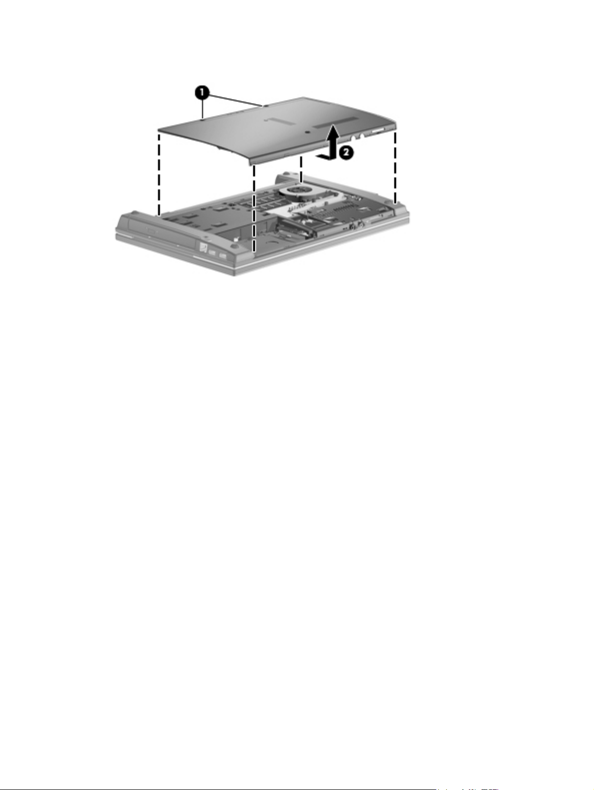
2. Slide the service door (2) away from the computer.
Reverse this procedure to install the service door.
50 Chapter 4 Removal and replacement procedures
Page 61

Hard drive
NOTE: The hard drive spare part kit includes a hard drive bracket.
Description Spare part number
500-GB, 7200-rpm hard drive for use in computers with 39.6-cm (15.6-in) displays 611029-001
500-GB, 5400-rpm hard drive for use in computers with 39.6-cm (15.6-in) displays 614956-001
320-GB, 7200-rpm hard drive for use in computers with 39.6-cm (15.6-in) displays 611028-001
320-GB, 5400-rpm hard drive for use in computers with 39.6-cm (15.6-in) displays 614955-001
250-GB, 7200-rpm hard drive for use in computers with 39.6-cm (15.6-in) displays 611027-001
250-GB, 5400-rpm hard drive for use in computers with 39.6-cm (15.6-in) displays 614523-001
160-GB, 7200-rpm hard drive for use in computers with 39.6-cm (15.6-in) displays 614522-001
160-GB, 5400-rpm hard drive for use in computers with 39.6-cm (15.6-in) displays 615844-001
500-GB, 7200-rpm hard drive 608139-001
500-GB, 5400-rpm hard drive 614958-001
320-GB, 7200-rpm hard drive 608138-001
320-GB, 5400-rpm hard drive 614957-001
250-GB, 7200-rpm hard drive 608137-001
250-GB, 5400-rpm hard drive 493994-001
160-GB, 7200-rpm hard drive 455954-001
160-GB, 5400-rpm hard drive 615040-001
Before removing the hard drive, follow these steps:
1. Shut down the computer. If you are unsure whether the computer is off or in Hibernation, turn
the computer on, and then shut it down through the operating system.
2. Disconnect all external devices connected to the computer.
3. Disconnect the power from the computer by first unplugging the power cord from the AC outlet
and then unplugging the AC adapter from the computer.
4. Remove the battery (see
5. Remove the service door (see
Battery on page 48).
Service door on page 49).
Remove the hard drive from a 39.6-cm (15.6-in) computer:
1. Position the computer right-side up with the front toward you.
2. Remove the two Phillips PM2.5×6.0 screws (1) and loosen the Phillips PM2.5×11.0 captive
screw (2) that secure the hard drive to the computer.
3. Grasp the mylar tab on the hard drive and slide the hard drive (3) to the left to disconnect it from
the system board.
Component replacement procedures 51
Page 62

4. Remove the hard drive (4) from the hard drive bay.
Remove the hard drive from a 35.6-cm (14-in) or 33.8-cm (13.3-in) computer:
1. Position the computer right-side up with the front toward you.
2. Remove the two Phillips PM2.5×6.0 screws (1) and loosen the Phillips PM2.5×4.0 captive screw
(2) that secure the hard drive to the computer.
3. Grasp the mylar tab on the hard drive and slide the hard drive (3) to the left to disconnect it from
the system board.
52 Chapter 4 Removal and replacement procedures
Page 63

4. Remove the hard drive (4) from the hard drive bay.
To remove the hard drive bracket, follow these steps:
1. If it is necessary to replace the hard drive bracket, remove the two Phillips PM3.0×4.0 hard drive
bracket screws (1) from each side of the hard drive.
2. Lift the bracket (2) straight up to remove it from the hard drive.
Reverse this procedure to reassemble and install the hard drive.
Component replacement procedures 53
Page 64

Memory module
NOTE: When adding a second memory module, be sure it is the same type and speed as the
installed memory module.
Description Spare part number
2-GB (PC3-10600, 1333-MHz, DDR3) 598856-001
1-GB (PC3-10600, 1333-MHz, DDR3) 598859-001
Before removing the memory module, follow these steps:
1. Shut down the computer. If you are unsure whether the computer is off or in Hibernation, turn
the computer on, and then shut it down through the operating system.
2. Disconnect all external devices connected to the computer.
3. Disconnect the power from the computer by first unplugging the power cord from the AC outlet
and then unplugging the AC adapter from the computer.
4. Remove the battery (see
5. Remove the service door (see
Battery on page 48).
Service door on page 49).
Remove the memory module:
1. Position the computer right-side up with the front toward you.
2. Spread the retaining tabs (1) on each side of the memory module slot to release the memory
module. (The edge of the module opposite the slot rises away from the computer.)
3. Remove the memory module (2) by pulling the module away from the slot at an angle.
NOTE: Memory modules are designed with a notch to prevent incorrect insertion into the
memory module slot.
Reverse this procedure to install a memory module.
54 Chapter 4 Removal and replacement procedures
Page 65

WLAN module
Description Spare part number
Broadcom 4312 802.11b/g WLAN modules
For use in Antigua and Barbuda, Barbados, Belize, Canada, the Cayman Islands, Guam,
●
Puerto Rico, Trinidad and Tobago, the U.S. Virgin Islands, and the United States
For use in Afghanistan, Albania, Algeria, Andorra, Angola, Antigua and Barbuda, Argentina,
●
Armenia, Aruba, Australia, Austria, Azerbaijan, the Bahamas, Bahrain, Bangladesh,
Barbados, Belarus, Belgium, Belize, Benin, Bermuda, Bhutan, Bolivia, Bosnia and
Herzegovina, Botswana, Brazil, the British Virgin Islands, Brunei, Bulgaria, Burkina Faso,
Burundi, Cameroon, Cape Verde, the Central African Republic, Chad, Chile, the People's
Republic of China, Colombia, Comoros, the Congo, Costa Rica, Croatia, Cyprus, the Czech
Republic, Denmark, Djibouti, Dominica, the Dominican Republic, East Timor, Ecuador,
Egypt, El Salvador, Equitorial Guinea, Eritrea, Estonia, Ethiopia, Fiji, Finland, France, French
Guiana, Gabon, Gambia, Georgia, Germany, Ghana, Gibraltar, Greece, Grenada,
Guadeloupe, Guatemala, Guinea, Guinea-Bissau, Guyana, Haiti, Honduras, Hong Kong,
Hungary, Iceland, India, Ireland, Israel, Italy, the Ivory Coast, Jamaica, Jordan, Kazakhstan,
Kenya, Kiribati, Kyrgyzstan, Laos, Latvia, Lebanon, Lesotho, Liberia, Liechtenstein,
Lithuania, Luxembourg, Macedonia, Madagascar, Malawi, Malaysia, the Maldives, Mali,
Malta, the Marshall Islands, Martinique, Mauritania, Mauritius, Mexico, Micronesia, Monaco,
Mongolia, Montenegro, Morocco, Mozambique, Namibia, Nauru, Nepal, the Nether Antilles,
the Netherlands, New Zealand, Nicaragua, Niger, Nigeria, Norway, Oman, Pakistan, Palau,
Panama, Papua New Guinea, Paraguay, Peru, the Philippines, Poland, Portugal, the
Republic of Moldova, Romania, Russia, Rwanda, Samoa, San Marino, Sao Tome and
Principe, Saudi Arabia, Senegal, Serbia, the Seychelles, Sierra Leone, Singapore, Slovakia,
Slovenia, the Solomon Islands, Somalia, South Africa, South Korea, Spain, Sri Lanka, St.
Kitts and Nevis, St. Lucia, St. Vincent and the Grenadines, Suriname, Swaziland, Sweden,
Switzerland, Taiwan, Tajikistan, Tanzania, Togo, Tonga, Trinidad and Tobago, Tunisia,
Turkey, Turkmenistan, Tuvalu, Uganda, Ukraine, the United Arab Emirates, the United
Kingdom, Uruguay, Uzbekistan, Vanuatu, Venezuela, Vietnam, Yemen, Zaire, Zambia, and
Zimbabwe
Broadcom 4313AGN 802.11a/b/g/draft-n WiFi Adapter 593836-001
504593-003
504593-004
Atheros 9285G 802.11 b/g/n WiFi Adapter for use in all countries and regions 605560-005
Realtek RTL8191SE802.11 b/g/n WiFi Adapter for use in all countries and regions 593533-001
CAUTION: To prevent an unresponsive system, replace the wireless module only with a wireless
module authorized for use in the computer by the governmental agency that regulates wireless
devices in your country or region. If you replace the module and then receive a warning message,
remove the module to restore computer functionality, and then contact technical support through Help
and Support.
Before removing the WLAN module, follow these steps:
1. Shut down the computer. If you are unsure whether the computer is off or in Hibernation, turn
the computer on, and then shut it down through the operating system.
2. Disconnect all external devices connected to the computer.
3. Disconnect the power from the computer by first unplugging the power cord from the AC outlet
and then unplugging the AC adapter from the computer.
4. Remove the battery (see
5. Remove the service door (see
Battery on page 48).
Service door on page 49).
Component replacement procedures 55
Page 66

Remove the WLAN module:
1. Disconnect the WLAN antenna cables (1) from the terminals on the WLAN module.
NOTE: The black WLAN antenna cable is connected to the WLAN module “Main” terminal.
The white WLAN antenna cable is connected to the WLAN module “Aux” terminal.
2. Remove the two Phillips PM2.0×2.5 screws (2) that secure the WLAN module to the computer.
(The edge of the module opposite the slot rises away from the computer.)
3. Remove the WLAN module (3) by pulling the module away from the slot at an angle.
Reverse this procedure to install the WLAN module.
56 Chapter 4 Removal and replacement procedures
Page 67

Optical drive
NOTE: All optical drive spare part kits include an optical drive bezel.
Description Spare part number
DVD±RW Double-Layer Drive with LightScribe (includes bezel) 608140-001
DVD-ROM Drive (includes bezel) 608141-001
Before removing the optical drive, follow these steps:
1. Shut down the computer. If you are unsure whether the computer is off or in Hibernation, turn
the computer on, and then shut it down through the operating system.
2. Disconnect all external devices connected to the computer.
3. Disconnect the power from the computer by first unplugging the power cord from the AC outlet
and then unplugging the AC adapter from the computer.
4. Remove the battery (see
5. Remove the service door (see
Battery on page 48).
Service door on page 49).
Remove the optical drive:
1. Position the computer with the right side toward you.
2. Remove the Torx M2.5×6.0 screw (1) that secures the optical drive to the computer.
3. Insert a flat-bladed screwdriver or similar tool into the optical drive tab access (2) and press the
tab to the right to release the optical drive from the computer.
4. Remove the optical drive (3) from the computer.
5. If it is necessary to replace the optical drive bracket, position the optical drive with the rear
toward you.
6. Remove the two Phillips PM2.0×2.0 screws (1) that secure the optical drive bracket to the optical
drive.
Component replacement procedures 57
Page 68

7. Remove the optical drive bracket (2).
Reverse this procedure to reassemble and install an optical drive.
58 Chapter 4 Removal and replacement procedures
Page 69

Fan
Description Spare part number
Fan for use in 39.6-cm (15.6-in) computer models 605791-001
Fan for use in 33.8-cm (13.3-in) and 35.6-cm (14.5-in) computer models 605787-001
Before removing the fan, follow these steps:
1. Shut down the computer. If you are unsure whether the computer is off or in Hibernation, turn
the computer on, and then shut it down through the operating system.
2. Disconnect all external devices connected to the computer.
3. Disconnect the power from the computer by first unplugging the power cord from the AC outlet
and then unplugging the AC adapter from the computer.
4. Remove the battery (see
5. Remove the service door (see
Battery on page 48).
Service door on page 49).
Remove the fan:
1. Position the computer upside down with the front toward you.
2. Disconnect the fan cable (1) from the system board .
3. Remove the Phillips PM2.0×3.0 screw (2) that secures the fan, and then remove the fan (3).
Reverse this procedure to install the fan.
Component replacement procedures 59
Page 70

Heat sink
NOTE: The heat sink spare part kit includes replacement thermal material.
Description Spare part number
Heat sink for use in computers with UMA graphics subsystems 611804-001
Heat sink for use in computers with discrete graphics subsystems NB 611805-001
Heat sink for use in computers with discrete graphics subsystems CPU 615355-001
Before removing the heat sink, follow these steps:
1. Shut down the computer. If you are unsure whether the computer is off or in Hibernation, turn
2. Disconnect all external devices connected to the computer.
3. Disconnect the power from the computer by first unplugging the power cord from the AC outlet
the computer on, and then shut it down through the operating system.
and then unplugging the AC adapter from the computer.
4. Remove the battery (see
5. Remove the service door (see
6. Remove the fan (see
Battery on page 48).
Service door on page 49).
Fan on page 59).
Remove the heat sink on computers with UMA graphics subsystems:
1. Position the computer right-side up with the front facing you.
2. Following the numbered sequence stamped into the heat sink, loosen the captive screws (1) and
(2) around the processor.
3. Raise the end of the heat sink (3) to free it from the system board components and then remove
the heat sink (4) from the system board.
60 Chapter 4 Removal and replacement procedures
Page 71

Remove the heat sink on computers with discrete graphics subsystems:
1. Position the computer right-side up with the front facing you.
2. Following the numbered sequence stamped into the heat sink, loosen the captive screws (1) and
(2) around the processor.
3. Lift the heat sink (3) from the system board.
Following the numbered sequence stamped into the heat sink, reverse the above procedure to install
the heat sink.
Component replacement procedures 61
Page 72

Processor
NOTE: The processor spare part kit includes replacement thermal material.
Description Spare part number
AMD Athlon™ II Dual-Core P320 2.1-GHz, 2MB L2 594165–001
AMD Sempron™ Single-Core V120 2-GHz, 2MB L2 594171–001
AMD Turion™ II Dual-Core, P520 2.3-GHz, 2MB L2 594173–001
AMD Phenom II Champlain P820 25W 594167-001
Before removing the processor, follow these steps:
1. Shut down the computer. If you are unsure whether the computer is off or in Hibernation, turn
2. Disconnect all external devices connected to the computer.
3. Disconnect the power from the computer by first unplugging the power cord from the AC outlet
the computer on, and then shut it down through the operating system.
and then unplugging the AC adapter from the computer.
4. Remove the battery (see
5. Remove the service door (see
6. Remove the fan (see
7. Remove the heat sink (see
Battery on page 48).
Service door on page 49).
Fan on page 59).
Heat sink on page 60).
Remove the processor:
1. Position the computer right-side up with the front toward you.
2. Use a flat-bladed screwdriver to turn the processor locking screw (1) one-half turn
counterclockwise until you hear a click.
62 Chapter 4 Removal and replacement procedures
Page 73

3. Lift the processor (2) straight up and remove it.
NOTE: When you install the processor, the gold triangle (3) on the processor must be aligned
with the triangle (4) embossed on the processor socket.
Reverse this procedure to install the processor.
Component replacement procedures 63
Page 74

Palm rest
Description Spare part number
Palm rest for Compaq brand units with 33.8-cm (13.3-in) displays (includes TouchPad, TouckPad
board, and 2 cables)
Palm rest for Compaq brand units with 33.8-cm (13.3-in) displays (includes TouchPad, TouchPad
board, and 2 cables), Red
Palm rest for HP brand units with 39.6-cm (15.6-in) displays (includes TouchPad, TouchPad
board, and 2 cables)
Palm rest for HP brand units with 35.6-cm (14-in) displays (includes TouchPad, TouchPad board,
and 2 cables)
605779-001
616602-001
605782-001
605780-001
Before removing the palm rest, follow these steps:
1. Shut down the computer. If you are unsure whether the computer is off or in Hibernation, turn
the computer on, and then shut it down through the operating system.
2. Disconnect all external devices connected to the computer.
3. Disconnect the power from the computer by first unplugging the power cord from the AC outlet
and then unplugging the AC adapter from the computer.
4. Remove the battery (see
5. Remove the service door (see
Battery on page 48).
Service door on page 49).
Remove the palm rest on 39.6-cm (15.6-in) computers:
1. Position the computer right side up with the display open.
2. Pull up (1) on the top edge of the palm rest nearest the keyboard. With the palm rest at an angle,
slide the unit (2) to release the latches at its base.
64 Chapter 4 Removal and replacement procedures
Page 75

3. Release the ZIF connector (1) to which the TouchPad cable is connected, and then disconnect
the cable (2) from the system board.
4. Remove the palm rest.
Remove the palm rest on 35.6-cm (14-in) or 33.8-cm (13.3-in) computers:
1. Position the computer upside down with the front toward you.
2. Remove the Torx M2.5×6.0 screw that secures the palm rest to the computer.
Component replacement procedures 65
Page 76

3. Turn the computer over, rotate the palm rest up (1) and slide the palm rest to the right (2) to
release it from the computer.
4. Release the ZIF connector (1) to which the TouchPad cable is connected, and then disconnect
the cable (2) from the system board.
5. Remove the palm rest.
Reverse this procedure to install the palm rest.
66 Chapter 4 Removal and replacement procedures
Page 77

Keyboard
Description Spare part number
Keyboards for use in computers with 39.6-cm (15.6-in) displays 605814-xx1
Keyboards for use in computers with 35.6-cm (14.3-in) and 33.8-cm (13.3-in) displays 605813-xx1
NOTE: For a detailed list of available keyboards, see
Sequential part number listing on page 35.
Before removing the keyboard, follow these steps:
1. Shut down the computer. If you are unsure whether the computer is off or in Hibernation, turn
the computer on, and then shut it down through the operating system.
2. Disconnect all external devices connected to the computer.
3. Disconnect the power from the computer by first unplugging the power cord from the AC outlet
and then unplugging the AC adapter from the computer.
4. Remove the battery (see
5. Remove the service door (see
6. Remove the palm rest (see
Battery on page 48).
Service door on page 49).
Palm rest on page 64).
Remove the keyboard on 39.6-cm (15.6-in) computers:
1. Position the computer upside down with the rear toward you.
2. Remove the three Phillips PM2.5×3.0 broadhead black screws (1) and three Torx M2.5×6.0
screws (2) that secure the keyboard.
Component replacement procedures 67
Page 78

3. Turn the unit over, lift the top edge of the keyboard (1) and slide it (2) towards the display.
4. Rest the keyboard on its edge and slide the keyboard back toward the display then, release the
ZIF connector (1) to which the keyboard cable is attached, and disconnect the keyboard cable
(2) from the system board.
Remove the keyboard on 35.6-cm (14.0-in) and 33.8-cm (13.3-in) computers:
1. Position the computer upside down with the rear toward you.
68 Chapter 4 Removal and replacement procedures
Page 79

2. Remove two Phillips PM2.5×3.0 broadhead black screws (1), one Phillips PM2.5×3.0 broadhead
silver screw (2), and two Torx M2.5×6.0 screws (3) that secure the keyboard.
3. Turn the unit over, lift the top edge of the keyboard (1) and slide it (2) towards the display.
Component replacement procedures 69
Page 80

4. Rest the keyboard on its edge and slide the keyboard back toward the display then, release the
ZIF connector (1) to which the keyboard cable is attached, and disconnect the keyboard cable
(2) from the system board.
Reverse this procedure to install the keyboard.
70 Chapter 4 Removal and replacement procedures
Page 81
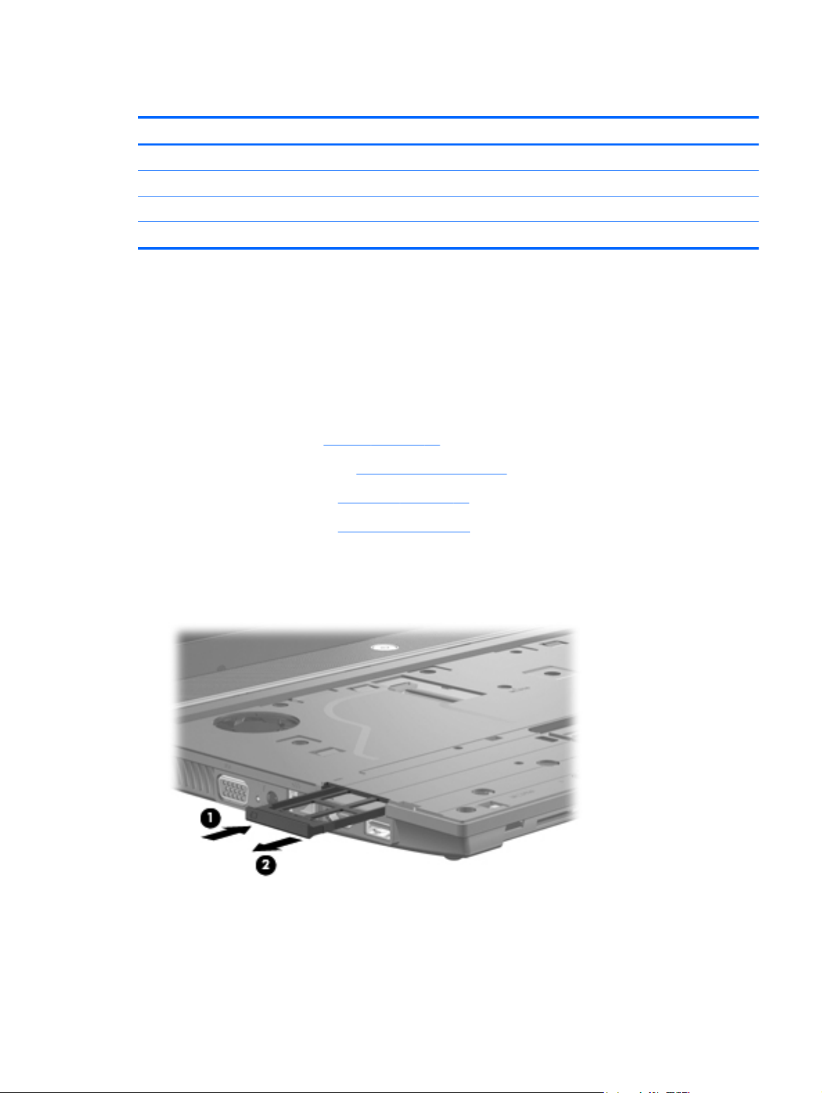
Top cover
Description Spare part number
Top cover for use in Compaq brand computers with 33.8-cm (13.3-in) displays 605774-001
Top cover for use in Compaq brand computers with 33.8-cm (13.3-in) displays, red 616601-001
Top cover for use in HP brand computers with 39.6-cm (15.6-in) displays 605777-001
Top cover for use in HP brand computers with 35.6-cm (14.0-in) displays 605775-001
Before removing the top cover, follow these steps:
1. Shut down the computer. If you are unsure whether the computer is off or in Hibernation, turn
2. Disconnect all external devices connected to the computer.
3. Disconnect the power from the computer by first unplugging the power cord from the AC outlet
the computer on, and then shut it down through the operating system.
and then unplugging the AC adapter from the computer.
4. Remove the battery (see
5. Remove the service door (see
6. Remove the palm rest (see
7. Remove the keyboard (see
Battery on page 48).
Service door on page 49).
Palm rest on page 64).
Keyboard on page 67).
Remove the top cover on a 39.6-cm (15.6-in) computer:
1. With the display panel in the open position, press in (1) of the ExpressCard to release it and then
pull the card (2) from the computer.
2. Position the computer upside down with the front toward you.
Component replacement procedures 71
Page 82

3. Remove the nine Torx M2.5×6.0 screws (1), three Phillips PM2.5×3.0 black broadhead screws
(2), and three Phillips PM2.0×3.0 screws (3).
4. Turn the computer over so it is right-side up and remove four Torx M2.5×6.0 screws.
72 Chapter 4 Removal and replacement procedures
Page 83

5. Release the ZIF connector (1) and remove the power switch cable (2).
6. Rotate the top cover up (1) and remove it from the base enclosure (2).
Component replacement procedures 73
Page 84

Remove the top cover on a 35.6-cm (14.0-in) and 33.8-cm (13.3-in) computer:
1. With the display panel in the open position, press in (1) of the ExpressCard to release it and then
pull the card (2) from the computer.
2. Position the computer upside down with the front toward you.
3. Remove the two Phillips PM2.0×2.0 screws (1) located in the battery bay, the five Torx M2.5×6.0
screws (2), (3), (4), and (5), and the two Phillips PM2.0×3.0 screws (6) located in the recess
near the optical drive.
74 Chapter 4 Removal and replacement procedures
Page 85

4. Turn the computer over so it is right-side up and remove five Torx M2.5×6.0 screws.
5. Release the ZIF connector (1) and disconnect the power switch cable (2).
Component replacement procedures 75
Page 86

6. Rotate the top cover up (1) and off the base enclosure (2).
Reverse this procedure to install the top cover.
Power switch board
The spare part number for the power switch board used in all models is 605794-001.
Before removing the power switch board, follow these steps:
1. Shut down the computer. If you are unsure whether the computer is off or in Hibernation, turn
the computer on, and then shut it down through the operating system.
2. Disconnect all external devices connected to the computer.
3. Disconnect the power from the computer by first unplugging the power cord from the AC outlet
and then unplugging the AC adapter from the computer.
4. Remove the battery (see
5. Remove the service door (see
6. Remove the keyboard (see
Battery on page 48).
Service door on page 49).
Keyboard on page 67).
76 Chapter 4 Removal and replacement procedures
Page 87

Remove the power switch board:
1. Release the ZIF connector (1) and disconnect the ribbon cable (2) from the system board.
2. Remove the Phillips M2.5×3.0 broadhead screw (1) that secures the board to the base pan,
raise the end of the board (2), and then slide the board out of the retainer (3).
Reverse this procedure to install the power switch board.
Component replacement procedures 77
Page 88

Bluetooth module
NOTE: The Bluetooth module spare part number is 537921-001 and is used in all countries and
regions except Japan and Asia Pacific countries and regions. The Bluetooth module cable is included
in the Cable Kit, spare part number 605793-001. See
part number information.
Before removing the Bluetooth module, follow these steps:
1. Shut down the computer. If you are unsure whether the computer is off or in Hibernation, turn
the computer on, and then shut it down through the operating system.
2. Disconnect all external devices connected to the computer.
3. Disconnect the power from the computer by first unplugging the power cord from the AC outlet
and then unplugging the AC adapter from the computer.
Cables on page 31 for more Cable Kit spare
4. Remove the battery (see
5. Remove the palm rest (see
6. Remove the keyboard (see
7. Remove the top cover (see
Remove the Bluetooth module on 39.6-cm (15.6-in) computers:
1. Position the computer right-side up with the front toward you.
2. Disconnect the Bluetooth cable (1) from the system board and remove the antenna (2) from the
base enclosure. The antenna is held to the base enclosure with adhesive.
Battery on page 48).
Palm rest on page 64).
Keyboard on page 67).
Top cover on page 71).
Remove the Bluetooth module on 35.6-cm (14.0-in) and 33.8-cm (13.3-in) computers:
1. Position the computer right-side up with the front toward you.
78 Chapter 4 Removal and replacement procedures
Page 89

2. Disconnect the Bluetooth cable (1) from the system board and remove the antenna (2) from the
base enclosure. The antenna is held to the base enclosure with adhesive.
Reverse this procedure to install the Bluetooth module.
USB connector assembly
Description Spare Part Number
USB board with cable 605796-001
USB board for use on system boards with UMA graphics subsystem 622615-001
Before removing the USB connector assembly, follow these steps:
1. Shut down the computer. If you are unsure whether the computer is off or in Hibernation, turn
the computer on, and then shut it down through the operating system.
2. Disconnect all external devices connected to the computer.
3. Disconnect the power from the computer by first unplugging the power cord from the AC outlet
and then unplugging the AC adapter from the computer.
4. Remove the battery (see
5. Remove the palm rest (see
6. Remove the keyboard (see
7. Remove the top cover (see
Battery on page 48).
Palm rest on page 64).
Keyboard on page 67).
Top cover on page 71).
Remove the USB connector assembly on 39.6-cm (15.6-in) computers:
1. Position the computer right-side up with the right side toward you.
2. Release the ZIF connector (1) and remove the cable (2) from the system board.
Component replacement procedures 79
Page 90

3. Remove the Torx M2.5×6.0 screw (3) then, lift the USB connector assembly (4) from the base
enclosure.
Remove the USB connector assembly on 35.6-cm (14.0-in) and 33.8-cm (13.3-in) computers:
1. Position the computer right-side up with the right side toward you.
2. Release the ZIF connector (1) and remove the cable (2) from the system board.
3. Lift the USB connector assembly (3) that is held on the base enclosure with adhesive.
Reverse this procedure to install the USB connector assembly.
80 Chapter 4 Removal and replacement procedures
Page 91

Speaker
The spare part number for the speaker used in all models is 605792-001.
Before removing the speaker, follow these steps:
1. Shut down the computer. If you are unsure whether the computer is off or in Hibernation, turn
2. Disconnect all external devices connected to the computer.
3. Disconnect the power from the computer by first unplugging the power cord from the AC outlet
the computer on, and then shut it down through the operating system.
and then unplugging the AC adapter from the computer.
4. Remove the battery (see
5. Remove the service door (see
6. Remove the palm rest (see
7. Remove the keyboard (see
8. Remove the top cover (see
Remove the speaker:
1. Disconnect the speaker cable from the connector (1) on the system board.
2. Remove the two screws from the speaker (2).
3. Lift the speaker up (3), and then release the cable from the cable retainers (4).
4. Remove the speaker and cable from the base enclosure.
Battery on page 48).
Service door on page 49).
Palm rest on page 64).
Keyboard on page 67).
Top cover on page 71).
Reverse this procedure to install the speaker.
Component replacement procedures 81
Page 92

Display assembly
Description Spare part number
39.6-cm (15.6-in) HD BrightView display assembly for use in computers equipped with
●
webcam (1366×768 resolution)
39.6-cm (15.6-in) HD BrightView display assembly for use in computers without webcam
●
(1366×768 resolution)
39.6-cm (15.6-in) HD AntiGlare display assembly for use in computers equipped with
●
webcam (1366×768 resolution)
39.6-cm (15.6-in HD AntiGlare display assembly for use in computers equipped without
●
webcam (1366×768 resolution)
35.6-cm (14.0-in) HD BrightView display assembly for use in computers equipped with
●
webcam (1366×768 resolution)
35.6-cm (14.0-in) HD BrightView display assembly for use in computers without webcam
●
(1366×768 resolution)
35.6-cm (14.0-in) HD AntiGlare display assembly for use in computers equipped with
●
webcam (1366×768 resolution)
35.6-cm (14.0-in) HD AntiGlare display assembly for use in computers without webcam
●
(1366×768 resolution)
33.8-cm (13.3-in) HD BrightView display assembly for use in computers equipped with
●
webcam and WLAN (1366×768 resolution)
33.8-cm (13.3-in) HD BrightView display assembly for use in computers with WLAN but
●
without webcam (1366×768 resolution)
33.8-cm (13.3-in) HD AntiGlare display assembly for use in computers equipped with
●
webcam and WLAN (1366×768 resolution)
605804-001
605803-001
605802-001
605801-001
605808-001
605807-001
605806-001
605805-001
605812-001
605811-001
605810-001
33.8-cm (13.3-in) HD AntiGlare display assembly for use in computers with WLAN but
●
without webcam (1366×768 resolution)
33.8-cm (13.3-in) HD AntiGlare display assembly for use in computers with WLAN but
●
without webcam (1366×768 resolution), red
33.8-cm (13.3-in) HD AntiGlare display assembly for use in computers equipped with
●
webcam and WLAN (1366×768 resolution), red
33.8-cm (13.3-in) HD BrightView display assembly for use in computers with WLAN but
●
without webcam (1366×768 resolution), red
33.8-cm (13.3-in) HD BrightView display assembly for use in computers equipped with
●
webcam and WLAN (1366×768 resolution), red
605809-001
616597-001
616598-001
616599-001
616600-001
Before removing the display assembly, follow these steps:
1. Shut down the computer. If you are unsure whether the computer is off or in Hibernation, turn
the computer on, and then shut it down through the operating system.
2. Disconnect all external devices connected to the computer.
3. Disconnect the power from the computer by first unplugging the power cord from the AC outlet
and then unplugging the AC adapter from the computer.
4. Remove the battery (see
Battery on page 48).
82 Chapter 4 Removal and replacement procedures
Page 93

5. Remove the service door (see Service door on page 49).
6. Remove the palm rest (see
7. Remove the keyboard (see
8. Remove the top cover (see
Remove the display on 39.6-cm (15.6-in) computers:
1. Orient the computer in its normal position, face up with the display open as far as it will
comfortably go.
CAUTION: Support the display assembly when removing the retaining screws. Failure to
support the display assembly can result in damage to the display assembly and other computer
components.
2. Disconnect the display cable (1) and the microphone cable (2) from the system board.
3. Release the WLAN cables from the cable run (3), being careful when pulling them through the
opening near the hard drive.
Palm rest on page 64).
Keyboard on page 67).
Top cover on page 71).
4. Remove eight Torx M2.5×6.0 screws (1) that secure the display to the base enclosure. Be
careful of the grounding cable (2) that is secured by one of the hinge retaining screws.
Component replacement procedures 83
Page 94
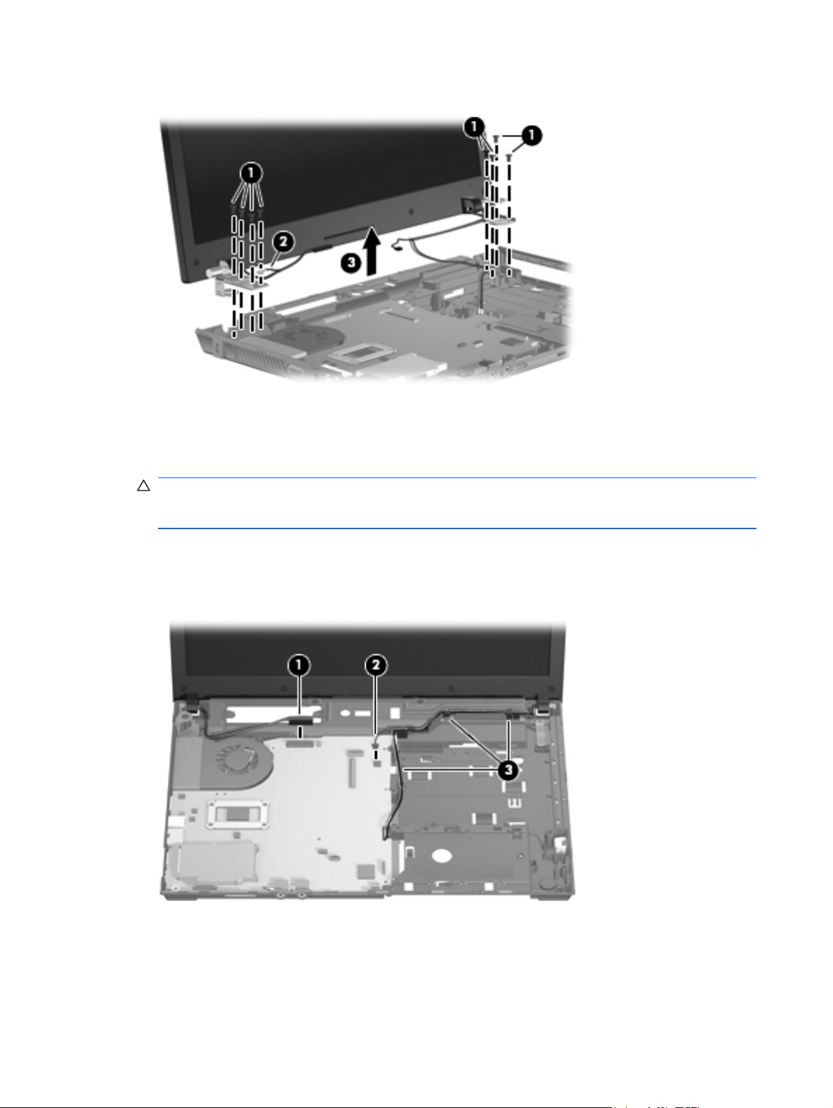
5. Lift the display assembly (3) from the base enclosure.
Remove the display on 35.6-cm (14.0-in) and 33.8-cm (13.3-in) computers:
1. Orient the computer in its normal position, face up with the display open as far as it will
comfortably go.
CAUTION: Support the display assembly when removing the retaining screws. Failure to
support the display assembly can result in damage to the display assembly and other computer
components.
2. Disconnect the display cable (1) and the microphone cable (2) from the system board.
3. Release the WLAN cables from the cable run (3), being careful when pulling them through the
opening near the hard drive.
4. Remove four Torx M2.5×6.0 screws (1) that secure the display to the base enclosure. Be careful
of the grounding cable (2) that is secured by one of the hinge retaining screws.
84 Chapter 4 Removal and replacement procedures
Page 95

5. Lift the display assembly (3) from the base enclosure.
Remove the display assembly:
1. If it is necessary to replace the display bezel, display enclosure, or display hinges, remove the
two mylar screw covers (1) and the 2 Phillips PM2.5×4.0 screws (2) that secure the display bezel
to the display assembly. The screw covers for the 39.6-cm (15.6-in) computer are available in
the Rubber Kit, spare part number 608931-001, and for the 35.6-cm (14.0-in) or 33.8-cm (13.3in) computer are available in the Rubber Kit, spare part number 605789-001.
2. Starting at the top of the display, flex the bezel (1) and work around the periphery of the bezel
(2) and (3) to release the bezel from the display enclosure .
Component replacement procedures 85
Page 96

3. Lift the bezel (4) from the display enclosure.
4. If it is necessary to replace the webcam module, disconnect the webcam cable from the module
(1), and pull the webcam module (2) that is attached with adhesive off the display enclosure. The
webcam module can be ordered by using spare part number 611026-001.
NOTE: To replace the webcam module in the display enclosure, align the holes on the
webcam module with the pins on the display enclosure and press onto the double-sided tape.
5. If it is necessary to replace the display hinges, remove the six Torx M2.5×6.0 screws (1) that
secure the display panel to the display enclosure.
86 Chapter 4 Removal and replacement procedures
Page 97

6. Lift the display panel up and out the housing (2).
Remove the display hinges from a 39.6-cm (15.6-in) computer:
1. Remove the eight Phillips PM2.0×3.0 screws (1) that secure the display hinges to the display
panel.
2. Remove the display hinges (2) by pulling them away from the display panel. The left and right
display hinges are available in the Hinge Kit, spare part number 605769-001.
Remove the display hinges from 35.6-cm (14.0-in) or 33.8-cm (13.3-in) computers:
1. Remove the six Phillips PM2.0×3.0 screws (1) that secure the display hinges to the display panel
Component replacement procedures 87
Page 98

2. Remove the display hinges (2) by pulling them away from the display panel. The left and right
display hinges are available in the Hinge Kit, spare part number 605768-001..
Remove the microphone:
1. Pull the microphone from its socket (1) on the display enclosure.
2. Remove the microphone cable from the raceway (2) in the display enclosure.
To remove the display cable assembly:
1. Place the display panel face down on a protected soft surface and remove the clear protector (1)
that covers the cable connector on the back of the panel.
88 Chapter 4 Removal and replacement procedures
Page 99

2. Remove the display cable (2) from the back of the display panel.
To remove the WLAN antennas:
1. Route the antenna cables (1) out of the routing channels in the inside of the display enclosure.
2. Peel the WLAN antenna receivers (2) from the enclosure
Reverse this procedure to assemble the display assembly.
Component replacement procedures 89
Page 100

System board
NOTE: The system board spare part kit includes replacement thermal material.
Description Spare part number
System board with UMA graphics and RTC battery with RS880M chipset 611803-001
System board with discrete graphics and RTC battery with RS880M chipset 611802-001
Before removing the system board, follow these steps:
1. Shut down the computer. If you are unsure whether the computer is off or in Hibernation, turn
the computer on, and then shut it down through the operating system.
2. Disconnect all external devices connected to the computer.
3. Disconnect the power from the computer by first unplugging the power cord from the AC outlet
and then unplugging the AC adapter from the computer.
4. Remove the battery (see
5. Remove the service door (see
6. Remove the hard drive (see
7. Remove the optical drive (see
8. Remove the fan (see
9. Remove the palm rest (see
10. Remove the keyboard (see
11. Remove the top cover (see
Battery on page 48).
Service door on page 49).
Hard drive on page 51).
Optical drive on page 57).
Fan on page 59).
Palm rest on page 64).
Keyboard on page 67).
Top cover on page 71).
When replacing the system board, be sure that the following components are removed from the
defective system board and installed on the replacement system board:
Memory module (see
●
WLAN module (see
●
Modem module (see
●
Heat sink (see
●
Processor (see
●
Memory module on page 54)
WLAN module on page 55)
Modem module on page 97)
Heat sink on page 60)
Processor on page 62)
Audio board (see
●
Audio board on page 99)
Remove the system board on a 39.6-cm (15.6-in) computer:
1. Position the computer with the front toward you.
2. Release the audio ZIF connector (1) and disconnect the cable (2) from the left edge of the
system board.
90 Chapter 4 Removal and replacement procedures
 Loading...